US8289646B1 - Disk drive having a disk limiter that is disposed within an angular range relative to a base depression brim - Google Patents
Disk drive having a disk limiter that is disposed within an angular range relative to a base depression brimDownload PDFInfo
- Publication number
- US8289646B1 US8289646B1US12/822,452US82245210AUS8289646B1US 8289646 B1US8289646 B1US 8289646B1US 82245210 AUS82245210 AUS 82245210AUS 8289646 B1US8289646 B1US 8289646B1
- Authority
- US
- United States
- Prior art keywords
- disk
- disk drive
- base
- rotation axis
- spindle rotation
- Prior art date
- Legal status (The legal status is an assumption and is not a legal conclusion. Google has not performed a legal analysis and makes no representation as to the accuracy of the status listed.)
- Expired - Fee Related, expires
Links
- 230000002093peripheral effectEffects0.000claimsabstractdescription23
- 239000000463materialSubstances0.000claimsdescription9
- 230000005294ferromagnetic effectEffects0.000claimsdescription8
- 229910052751metalInorganic materials0.000claimsdescription8
- 239000002184metalSubstances0.000claimsdescription8
- 230000035939shockEffects0.000description14
- 230000005291magnetic effectEffects0.000description9
- 239000000853adhesiveSubstances0.000description3
- 230000001070adhesive effectEffects0.000description3
- 239000010410layerSubstances0.000description3
- 229920006324polyoxymethylenePolymers0.000description3
- 229920000106Liquid crystal polymerPolymers0.000description2
- 239000004977Liquid-crystal polymers (LCPs)Substances0.000description2
- 229930040373ParaformaldehydeNatural products0.000description2
- 229910052782aluminiumInorganic materials0.000description2
- XAGFODPZIPBFFR-UHFFFAOYSA-NaluminiumChemical compound[Al]XAGFODPZIPBFFR-UHFFFAOYSA-N0.000description2
- 230000033001locomotionEffects0.000description2
- 230000003287optical effectEffects0.000description2
- 230000000717retained effectEffects0.000description2
- 239000000758substrateSubstances0.000description2
- DHKHKXVYLBGOIT-UHFFFAOYSA-N1,1-DiethoxyethaneChemical compoundCCOC(C)OCCDHKHKXVYLBGOIT-UHFFFAOYSA-N0.000description1
- FYYHWMGAXLPEAU-UHFFFAOYSA-NMagnesiumChemical compound[Mg]FYYHWMGAXLPEAU-UHFFFAOYSA-N0.000description1
- 239000004677NylonSubstances0.000description1
- 239000004697PolyetherimideSubstances0.000description1
- 239000011354acetal resinSubstances0.000description1
- 125000000218acetic acid groupChemical groupC(C)(=O)*0.000description1
- 229910003481amorphous carbonInorganic materials0.000description1
- 229910052790berylliumInorganic materials0.000description1
- ATBAMAFKBVZNFJ-UHFFFAOYSA-Nberyllium atomChemical compound[Be]ATBAMAFKBVZNFJ-UHFFFAOYSA-N0.000description1
- 239000000919ceramicSubstances0.000description1
- 238000013016dampingMethods0.000description1
- 230000004907fluxEffects0.000description1
- 239000011521glassSubstances0.000description1
- 229920001519homopolymerPolymers0.000description1
- 230000001939inductive effectEffects0.000description1
- 238000002347injectionMethods0.000description1
- 239000007924injectionSubstances0.000description1
- 239000000314lubricantSubstances0.000description1
- 229910052749magnesiumInorganic materials0.000description1
- 239000011777magnesiumSubstances0.000description1
- 229920001778nylonPolymers0.000description1
- 239000004033plasticSubstances0.000description1
- 229920003023plasticPolymers0.000description1
- 239000004417polycarbonateSubstances0.000description1
- 229920000515polycarbonatePolymers0.000description1
- 229920001601polyetherimidePolymers0.000description1
- -1polyoxymethylenePolymers0.000description1
- 239000011241protective layerSubstances0.000description1
- 229910001220stainless steelInorganic materials0.000description1
- 239000010935stainless steelSubstances0.000description1
- 239000000725suspensionSubstances0.000description1
- 239000010409thin filmSubstances0.000description1
Images


Classifications
- G—PHYSICS
- G11—INFORMATION STORAGE
- G11B—INFORMATION STORAGE BASED ON RELATIVE MOVEMENT BETWEEN RECORD CARRIER AND TRANSDUCER
- G11B25/00—Apparatus characterised by the shape of record carrier employed but not specific to the method of recording or reproducing, e.g. dictating apparatus; Combinations of such apparatus
- G11B25/04—Apparatus characterised by the shape of record carrier employed but not specific to the method of recording or reproducing, e.g. dictating apparatus; Combinations of such apparatus using flat record carriers, e.g. disc, card
- G11B25/043—Apparatus characterised by the shape of record carrier employed but not specific to the method of recording or reproducing, e.g. dictating apparatus; Combinations of such apparatus using flat record carriers, e.g. disc, card using rotating discs
Definitions
- the typical hard disk driveincludes a head disk assembly (HDA) and a printed circuit board (PCB) attached to a disk drive base of the HDA.
- the head disk assemblyincludes at least one disk (such as a magnetic disk, magneto-optical disk, or optical disk), a spindle motor for rotating the disk, and a head stack assembly (HSA).
- the printed circuit board assemblyincludes electronics and firmware for controlling the rotation of the spindle motor, for controlling the position of the HSA, and for providing a data transfer channel between the disk drive and its host.
- the head stack assemblytypically includes an actuator, at least one head gimbal assembly (HGA), and a flex cable assembly.
- HGAhead gimbal assembly
- Each HGAincludes a head for reading and writing data from and to the disk.
- the headtypically includes an air bearing slider and a magnetic transducer that comprises a writer and a read element.
- the magnetic transducer's writermay be of a longitudinal or perpendicular design, and the read element of the magnetic transducer may be inductive or magnetoresistive.
- the headmay include a mirror and an objective lens for focusing laser light on an adjacent disk surface.
- the actuatorDuring operation of the disk drive, the actuator must rotate to position the heads adjacent desired information tracks on the disk.
- One or more actuator armsextend from the actuator body.
- An actuator coilis supported by the actuator body opposite the actuator arms.
- the actuator coilis configured to interact with one or more fixed magnets in the HDA, typically a pair, to form a voice coil motor.
- Many modern HDAsinclude a ramp adjacent the disk outer periphery. To prevent the heads from sliding off of the outer edge of the disk before they are properly unloaded, a portion of the ramp (that engages a lift tab of each HGA) typically must extend over the disk outer periphery.
- the disk(s)may still deflect significantly. Such disk deflection may be limited by contact between the disk(s) and the ramp, and/or other components such as the disk drive cover, and/or the disk drive base plate. Still, such limiting contact may be undesirable depending on the characteristics of the component being contacted by the disk. For example, the base plate and/or cover may have features against which disk contact is undesirable and could cause disk surface damage and associated loss of user data.
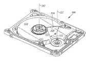
- FIG. 1Ais a top view of a disk drive according to an embodiment of the present invention.
- FIG. 1Bis an enlarged view of a portion of FIG. 1A .
- FIG. 2Ais an enlarged top view of a portion of a disk drive according to an embodiment of the present invention.
- FIG. 2Bis a side view of a portion of the disk drive shown in FIG. 2A .
- FIG. 3is a perspective view of a disk drive base, capable of use in an embodiment of the present invention.
- FIG. 4Ais an underside perspective view of a disk drive top cover, according to an embodiment of the present invention.
- FIG. 4Bis a side view of a portion of a disk drive that includes the top cover of FIG. 4A .
- FIG. 1Ais a top view of a disk drive 100 according to an embodiment of the present invention.
- FIG. 1Bis an enlarged top view of a portion of disk drive 100 .
- the disk drivecomprises a disk drive base 300 and a spindle 104 attached to the disk drive base 300 .
- the spindle 104defines a spindle axis of rotation 102 (normal to the page in FIG. 1A ).
- a disk 106has a top surface and an opposing bottom surface and is mounted on spindle 104 .
- the disk 106may comprise an aluminum, glass, or ceramic substrate, with the substrate being coated with a NiP under-layer, a thin-film magnetic layer, a diamond-like amorphous carbon protective layer, and a very thin lubricant layer.
- the disk 106defines a disk outer peripheral extent 107 .
- the disk drive 100 of FIG. 1may include a plurality of disks that are mounted on spindle 104 .
- disk 106may be a top disk below which one or more additional disks may be mounted on the spindle 104 .
- the actuator 110is attached to the disk drive base 300 .
- the actuator 110is typically fabricated from aluminum, magnesium, beryllium, or stainless steel, and pivots about a pivot bearing 112 that is inserted as a cartridge into a bore in the actuator.
- the pivot bearing 112is typically retained in the bore by a C-clip or tolerance ring but may be otherwise retained (e.g. by an adhesive).
- the actuator 110defines an actuator pivot axis 122 at the location of the pivot bearing 112 .
- the actuator pivot axis 122is substantially parallel to the spindle rotation axis 102 (normal to the page in FIGS. 1A and 1B ).
- the actuator 110includes at least one actuator arm 120 that extends away from the actuator pivot axis 122 , and an actuator coil 130 that extends away from the actuator pivot axis 122 in a direction generally opposite the actuator arm 120 .
- a portion of the actuator coil 130is obscured behind a top plate 132 of a yoke structure of a voice coil motor (VCM) in the views of FIGS. 1A and 1B .
- the top plate 132may support an upper permanent magnet of the VCM, and may be disposed over a bottom plate (not shown because obscured by the top plate 132 in the views of FIGS. 1A and 1B ) that may support a lower permanent magnet of the VCM.
- the top plate 132 and/or the bottom plateform a yoke and preferably comprise a ferromagnetic metal so as to provide a return path for magnetic flux from the permanent magnet(s).
- the ferromagnetic metal yoke structure including the top plate 132is preferably affixed to the disk drive base, for example by an adhesive, one or more fasteners, and/or magnetic attraction.
- a head gimbal assembly (HGA) 114is attached to the actuator 110 and may support a read head near its distal end.
- the HGA 114may also include a lift-tab at its distal end, that is in contact with a parking surface of a head loading ramp 150 (that is affixed to the disk drive base 300 ) with the disk drive 100 in a non-operational state. Specifically, at the beginning of a period of non-operation of the disk drive 100 , the actuator 110 swings the HGA 114 away from the spindle 104 and beyond the outer peripheral extent 107 of disk 106 .
- the lift-tab of the HGA 114then contacts the ramp 150 to separate or “unload” the read head from the surface of the disk 106 . After such unloading, the ramp 150 and its parking surface support the distal end of the HGA 114 , rather than the disk 106 providing such support.
- the ramp 150optionally but preferably includes a HGA motion-limiting feature to protect the HGA 114 from damage during a mechanical shock event that might occur during periods of non-operation of the disk drive 100 .
- a HGA motion-limiting featureis designed to interfere with extreme motions of the head and/or suspension assembly while the lift-tab of the HGA 114 resides in the parking region of the ramp 150 .
- such a HGA motion limiting featuremay prevent head-to-head contact between HGAs in response to mechanical shock and/or may reduce the risk of a vertical deflection of HGA 114 that might exceed its elastic range.
- the ramp 150may be fabricated from any suitable material having acceptable cost, dimensional stability, and tribological characteristics, although a material that can be injection molded is preferred.
- the ramp 150may comprise polyoxymethylene (POM), polycarbonate, a liquid crystal polymer (LCP), nylon, an acetal resin plastic or acetyl homopolymer, and/or polyetherimide, among other materials.
- a disk limiter protrusion 160protrudes from an edge of the VCM yoke top plate 132 towards the spindle rotation axis 102 .
- the disk limiter protrusion 160extends over the disk outer peripheral extent 107 in the non-operational state.
- extending “over”refers to an overlap as viewed parallel with the actuator pivot axis 122 (i.e. the disk limiter protrusion 160 extends closer to the spindle rotation axis 102 than is the disk outer peripheral extent 107 ).
- the disk limiter protrusion 160preferably extends over the disk outer peripheral extent 107 by a radial overlap distance (measured radially with respect to the spindle axis of rotation 102 ) in the range 0.1 mm to 2 mm.
- the VCM yoke top plate 132 and the disk limiter protrusion 160are a single component with material continuity rather than being an assembly of subcomponents.
- the disk limiter protrusion 160may be a distinct sub-component that is conventionally fastened or adhered to the VCM yoke top plate 132 , for example by a threaded fastener.
- a face of the disk limiter protrusion 160is preferably spaced, in a direction parallel to the actuator pivot axis 122 , between 0.3 mm and 0.8 mm from a surface of the disk 106 .
- the foregoing dimensionsmay advantageously enhance the robustness of hard disk drives to mechanical shocks that may occur under non-operating conditions.
- the head loading ramp 150also extends over the disk outer peripheral extent 107 .
- no stationary structure fixed to the disk drive base 300except the head loading ramp 150 and the disk limiter protrusion 160 , extends over the disk outer peripheral extent 107 with a spacing, measured in a direction parallel to the spindle rotation axis, that is less than 0.8 mm.
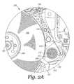
- FIG. 2Ais an enlarged top view of a portion of a disk drive 200 according to an embodiment of the present invention.
- FIG. 2Bis a side view of a portion of the disk drive 200 shown in FIG. 2A .
- Like numerical labelsare used to identify like components in the figure descriptions herein, for example to make the description of FIGS. 2A-2B more concise by not having to repeat the description of features that are similar to a previously described embodiment.
- a disk limiter protrusion 260protrudes from a edge of a VCM yoke top plate 232 towards the spindle rotation axis 102 .
- the disk limiter protrusion 260extends over the disk outer peripheral extent 107 in the non-operational state.
- the disk limiter protrusion 260preferably extends over the disk outer peripheral extent 107 by a radial overlap distance 282 (measured radially with respect to the spindle axis of rotation 102 ) in the range 0.1 mm to 2 mm.
- the VCM yoke top plate 232 and the disk limiter protrusion 260are a single component with material continuity rather than being an assembly of subcomponents.
- the disk limiter protrusion 260may be a distinct sub-component that is conventionally fastened or adhered to the VCM yoke top plate 232 .
- a face of the disk limiter protrusion 260is preferably spaced, by a clearance 284 measured in a direction parallel to the actuator pivot axis 122 , between 0.3 mm and 0.8 mm from a surface of the disk 106 .
- the foregoing dimensionsmay advantageously enhance the robustness of hard disk drives to mechanical shocks that may occur under non-operating conditions.
- FIG. 3is a perspective view of a disk drive base 300 , capable of use in an embodiment of the present invention.
- the disk drive base 300includes a first base surface 310 that faces the disk (e.g. disk 106 of FIG. 1 ).
- the disk drive base 300also includes a base depression 320 that faces the disk but that is disposed further from the disk than is the first base surface 310 .
- the base depression 320is bounded by a first base depression brim 332 , and a second base depression brim 334 , which are each disposed between the first base surface 310 and the base depression 320 .
- the first base depression brim 332may be spaced, in a direction parallel to the spindle rotation axis 102 , less than 0.8 mm from a surface of the disk 106 .
- the first base depression brim 332is oriented generally radially with respect to the spindle rotation axis 102 . That is, although the first base depression brim 332 is not oriented perfectly radially with respect to the spindle rotation axis 102 , its orientation is much nearer to being radial than tangential. Likewise in the embodiment of FIG. 3 , the second base depression brim 334 is also oriented generally radially with respect to spindle rotation axis 102 .
- An angle ⁇ about the spindle axis of rotation 102is may be formed between an imaginary radius that extends from the spindle rotation axis 102 over the first base depression brim 332 , and another imaginary radius that extends from the spindle rotation axis 102 over the second base depression brim 334 . That is, an angle ⁇ may be formed about the spindle axis of rotation 102 between the first base depression brim 332 and the second base depression brim 334 , so that 0 is the angular span of the base depression 320 about the spindle axis of rotation 102 . In certain embodiments, the angle ⁇ may be 90 degrees or less.
- the angular span of the disk limiter protrusion 160is no more than 20° about the spindle rotation axis 102 .
- the angular span of the disk limiter protrusion 260is no more than 20° about the spindle rotation axis 102 .
- a first imaginary radius that extends from the spindle rotation axis 102 over the first base depression brim 332is angularly disposed no more than 25° from any second imaginary radius that extends from the spindle rotation axis 102 to the disk limiter protrusion (e.g. disk limiter protrusion 160 of FIG. 1B or disk limiter protrusion 260 of FIGS. 2A-2B ).
- the foregoing angular inequalitiesmay desirably help the limiter protrusions 160 and 260 to constrain the disk 106 in such a way that less of the energy from mechanical shocks excites a disk umbrella mode response (with perhaps more energy exciting a disk and/or spindle rocking response).
- the foregoing angular inequalitiesmay also desirably avoid contact between the disk 106 and the first base depression brim 332 under conditions of mechanical shock.
- FIG. 4Ais an underside perspective view of a disk drive top cover 440 , according to an embodiment of the present invention.
- FIG. 4Bis a side view of a portion of a disk drive 400 that includes the top cover 440 of FIG. 4A .
- the top cover 440may be affixed to a disk drive base (e.g. the disk drive base 300 of FIG. 3 ), for example by fasteners through the holes 442 , 444 , 446 , and 448 that are shown in the periphery of the top cover 440 , to comprise a disk drive enclosure.
- a disk drive basee.g. the disk drive base 300 of FIG. 3
- the top cover 440may also include a disk limiter protrusion 460 that protrudes into the disk drive enclosure towards a disk 106 .
- the disk limiter protrusion 460 and the top cover 440may be a single component with material continuity rather than being an assembly of subcomponents.
- the disk limiter protrusion 460may be a subcomponent that is attached to the top cover 440 , for example by conventional adhesive or conventional fastener.
- a face of the disk limiter protrusion 460is preferably spaced, by a clearance 484 measured in a direction parallel to the actuator pivot axis, between 0.3 mm and 0.8 mm from a surface of the disk 106 .
- the foregoing dimensional rangemay advantageously enhance the robustness of hard disk drives to mechanical shocks that may occur under non-operating conditions.
- the angular span of the disk limiter protrusion 460 about the disk rotational axisis preferably no more than 20°.
- a first imaginary radius that extends from the spindle rotation axis 102 over the first base depression brim 332is preferably angularly disposed no more than 25° from any second imaginary radius that extends from the spindle rotation axis 102 to the disk limiter protrusion 460 (with the top cover 440 righted and attached to the disk drive base 300 ).
- the foregoing angular inequalitiesmay desirably help the disk limiter protrusion 460 constrain the disk 106 in such a way that less of the energy from mechanical shocks excites a disk umbrella mode response (with perhaps more energy exciting a disk and/or spindle rocking response).
- the foregoing angular inequalitiesmay also desirably avoid contact between the disk 106 and the first base depression brim 332 under conditions of mechanical shock.
Landscapes
- Moving Of Heads (AREA)
Abstract
Description
Claims (19)
Priority Applications (1)
| Application Number | Priority Date | Filing Date | Title |
|---|---|---|---|
| US12/822,452US8289646B1 (en) | 2010-06-24 | 2010-06-24 | Disk drive having a disk limiter that is disposed within an angular range relative to a base depression brim |
Applications Claiming Priority (1)
| Application Number | Priority Date | Filing Date | Title |
|---|---|---|---|
| US12/822,452US8289646B1 (en) | 2010-06-24 | 2010-06-24 | Disk drive having a disk limiter that is disposed within an angular range relative to a base depression brim |
Publications (1)
| Publication Number | Publication Date |
|---|---|
| US8289646B1true US8289646B1 (en) | 2012-10-16 |
Family
ID=46981763
Family Applications (1)
| Application Number | Title | Priority Date | Filing Date |
|---|---|---|---|
| US12/822,452Expired - Fee RelatedUS8289646B1 (en) | 2010-06-24 | 2010-06-24 | Disk drive having a disk limiter that is disposed within an angular range relative to a base depression brim |
Country Status (1)
| Country | Link |
|---|---|
| US (1) | US8289646B1 (en) |
Cited By (47)
| Publication number | Priority date | Publication date | Assignee | Title |
|---|---|---|---|---|
| US8446688B1 (en) | 2010-06-29 | 2013-05-21 | Western Digital Technologies, Inc. | Drive with circumferential disk limiter |
| US20130155546A1 (en)* | 2011-12-15 | 2013-06-20 | Western Digital Technologies, Inc. | Damper for disk drive |
| US8553356B1 (en) | 2011-11-21 | 2013-10-08 | Western Digital Technologies, Inc. | Disk limiter for disk drive |
| US8743509B1 (en) | 2010-05-10 | 2014-06-03 | Western Digital Technologies, Inc. | Disk drive having a head loading ramp and a disk limiter tab that projects from a side of an actuator arm |
| US8908319B1 (en) | 2013-04-18 | 2014-12-09 | Western Digital Technologies, Inc. | Disk drive with slow acting desiccant |
| US8908325B1 (en) | 2013-03-08 | 2014-12-09 | Western Digital Technologies, Inc. | Threaded disk clamping element with step on disk contact surface |
| US8941952B1 (en) | 2014-06-10 | 2015-01-27 | Western Digital Technologies, Inc. | Disk drive head stack assembly having a flexible printed circuit with bond pads having reduced capacitance |
| US8970984B1 (en) | 2014-04-29 | 2015-03-03 | Western Digital Technologies, Inc. | Grooved cylindrical seal with increased radial clearance for reduced cost disk drive spindle |
| US8995094B1 (en) | 2014-02-28 | 2015-03-31 | Western Digital Technologies, Inc. | Disk drive head suspension with a dual dimple and a flexure tongue with a piezoelectric microactuator |
| US9007716B1 (en) | 2012-09-24 | 2015-04-14 | Western Digital Technologies, Inc. | Spindle motor magnet diameter increase above head plane |
| US9019657B1 (en) | 2013-03-13 | 2015-04-28 | Western Digital Technologies, Inc. | Coined VCM tab to limit cover deflection under pinch load |
| US9025284B1 (en) | 2014-02-26 | 2015-05-05 | Western Digital Technologies, Inc. | Disk drive with self sealing screw attachment of actuator pivot |
| US9036295B1 (en) | 2011-12-20 | 2015-05-19 | Western Digital Technologies, Inc. | Information storage device with a damping insert sheet between a housing bay and a disk drive |
| US9058851B1 (en) | 2014-07-02 | 2015-06-16 | Western Digital Technologies, Inc. | Information-storage device including an oxygen absorbing device |
| US9099131B1 (en) | 2010-03-17 | 2015-08-04 | Western Digital Technologies, Inc. | Suspension assembly having a microactuator electrically connected to a gold coating on a stainless steel surface |
| US9099153B2 (en) | 2013-04-03 | 2015-08-04 | Western Digital Technologies, Inc. | Storage device with a cover supporting portion |
| US9116066B1 (en) | 2012-04-27 | 2015-08-25 | Western Digital Technologies, Inc. | Devices and methods for system-level disk drive vibration and shock testing |
| US9123387B1 (en) | 2014-08-21 | 2015-09-01 | WD Media, LLC | Magnetic recording drives with active photocatalytic filtration |
| US9129639B1 (en) | 2012-11-08 | 2015-09-08 | Western Digital Technologies, Inc. | Method of imbalance correction using a grooved disk clamp |
| US9147436B2 (en) | 2012-04-25 | 2015-09-29 | Western Digital Technologies, Inc. | Slim form factor disk drive comprising disk drive enclosure having an insular raised region |
| US9153262B1 (en) | 2015-03-26 | 2015-10-06 | Western Digital Technologies, Inc. | Disk drive actuator having a radially stepped pivot bore |
| US9159205B1 (en) | 2013-12-18 | 2015-10-13 | Western Digital Technologies, Inc. | Tamper-evident seals having adhesive-free areas to minimize rework time |
| US9165580B2 (en) | 2013-12-10 | 2015-10-20 | Western Digital Technologies, Inc. | Disk drive head suspension tail with stiffened edge alignment features |
| US9171560B1 (en) | 2014-09-26 | 2015-10-27 | Western Digital Technologies, Inc. | Sloping transition on a ramp of a hard disk drive |
| US9171583B1 (en) | 2015-03-23 | 2015-10-27 | Western Digital Technologies, Inc. | Disk drive having a top cover channel vented to a central cavity via a peripheral clearance gap |
| US9183889B1 (en) | 2015-03-23 | 2015-11-10 | Western Digital Technologies, Inc. | Disk drive having a top cover channel vented to a central cavity via a hole through a bottom land |
| US9190114B1 (en) | 2015-02-09 | 2015-11-17 | Western Digital Technologies, Inc. | Disk drive filter including fluorinated and non-fluorinated nanopourous organic framework materials |
| US9196275B1 (en) | 2014-03-12 | 2015-11-24 | Western Digital Technologies, Inc. | Magnetic head separator fin material to prevent particulate contamination on slider |
| US9196292B1 (en) | 2015-02-05 | 2015-11-24 | Western Digital Technologies, Inc. | Rotary spindle having a disk clamp bottom land facing and in contact with a shaft top land |
| US9196301B1 (en) | 2011-10-14 | 2015-11-24 | Western Digital Technologies, Inc. | Suspension clamp for clamping a disk drive suspension to an actuator arm |
| US9208825B1 (en) | 2013-08-07 | 2015-12-08 | Western Digital Technologies, Inc. | Disk drive having a conformal peripheral foil seal having an opening covered by a central metal cap |
| US9214174B1 (en) | 2010-10-29 | 2015-12-15 | Western Digital Technologies, Inc. | Method of manufacturing a disk drive head gimbal assembly having a flexure tail with folded bond pads |
| US9263070B1 (en) | 2014-11-05 | 2016-02-16 | Western Digital Technologies, Inc. | Actuator pivot assembly including a bonding adhesive barrier configured to reduce contamination |
| US9299384B1 (en) | 2012-08-02 | 2016-03-29 | Western Digital Technologies, Inc. | Ultra-thin HDD embedded disk clamp design |
| US9324344B1 (en) | 2013-12-10 | 2016-04-26 | Western Digital Technologies, Inc. | Disk drive head suspension tail with ground pad outside of bonding region |
| US9330695B1 (en) | 2013-12-10 | 2016-05-03 | Western Digital Technologies, Inc. | Disk drive head suspension tail with a noble metal layer disposed on a plurality of structural backing islands |
| US9379311B1 (en) | 2005-12-09 | 2016-06-28 | Western Digital Technologies, Inc. | Apparatus for manufacturing piezoelectric actuators |
| US9390736B1 (en) | 2014-03-13 | 2016-07-12 | Western Digital Technologies, Inc. | Magnetic head separator connected to a ramp |
| US9406333B1 (en) | 2015-11-10 | 2016-08-02 | Western Digital Technologies, Inc. | Disk drive having a stationary plate between disks with grooves adjacent fastener holes |
| US9472242B1 (en) | 2015-06-05 | 2016-10-18 | Western Digital Technologies, Inc. | Hard disk drive enclosure base with feed through flexure design and accompanying flexure |
| US9508393B1 (en) | 2015-06-25 | 2016-11-29 | Western Digital Technologies, Inc. | Hard disk drive enclosure base with a helium sealed gasket |
| US9514773B2 (en) | 2008-08-20 | 2016-12-06 | Western Digital Technologies, Inc. | Head stack assembly with a flexible printed circuit having a mouth centered between arms |
| US9524738B1 (en) | 2015-06-25 | 2016-12-20 | Western Digital Technologies, Inc. | Disk drive head gimbal assembly having a flexure tail with a dielectric layer that has regions of lesser thickness |
| US9564156B1 (en) | 2016-01-27 | 2017-02-07 | Western Digital Technologies, Inc. | Head gimbal assembly having a flexure tail with cover layer standoff islands |
| US9633680B2 (en) | 2010-10-29 | 2017-04-25 | Western Digital Technologies, Inc. | Head suspension having a flexure tail with a covered conductive layer and structural layer bond pads |
| US9662753B1 (en) | 2014-03-10 | 2017-05-30 | Western Digital Technologies, Inc. | Disk drive spindle with fluid journal bearing having increased radial clearance in axial end regions |
| US9908167B1 (en) | 2015-03-02 | 2018-03-06 | Western Digital Technologies, Inc. | Disk drive tolerance ring with edge rounding from opposite major faces |
Citations (51)
| Publication number | Priority date | Publication date | Assignee | Title |
|---|---|---|---|---|
| US4939611A (en) | 1988-10-20 | 1990-07-03 | Hewlett-Packard Company | Vertical displacement limit stop in a disk drive for preventing disk surface damage |
| US5231549A (en) | 1988-03-01 | 1993-07-27 | Conner Peripherals, Inc. | Disk drive apparatus with cam and follower for unloading heads |
| US5239431A (en) | 1992-02-26 | 1993-08-24 | Hewlett-Packard Company | Head lift limiter for a disk drive |
| US5453889A (en) | 1993-12-15 | 1995-09-26 | Integral Peripherals, Inc. | Disk drive with disk restraint for protection against non-operational shocks |
| US5541791A (en) | 1994-11-17 | 1996-07-30 | Quantum Corporation | Air guide for an aerodynamic actuator latch within a disk drive |
| US5625514A (en) | 1993-12-14 | 1997-04-29 | Sony Corporation | Disk Device |
| US5640290A (en) | 1994-09-27 | 1997-06-17 | International Business Machines Corporation | Shock-resistant structure for magnetic disk drive |
| US5757587A (en) | 1994-10-17 | 1998-05-26 | International Business Machines Corporation | Direct access storage device having a disk motion limiter for preventing disk data zone and spindle bearing damage |
| US5801899A (en) | 1995-10-06 | 1998-09-01 | Seagate Technology, Inc. | Mechanical shock protection for a disc drive |
| US5864444A (en) | 1996-09-30 | 1999-01-26 | Seagate Technology, Inc. | Actuator arm bumper in a disc drive |
| US5903409A (en) | 1997-01-17 | 1999-05-11 | International Business Machines Corporation | Method and means for maintaining data integrity in disk drives resulting from shock-induced contact between recording and access components during nonoperational periods |
| US5959807A (en) | 1996-06-24 | 1999-09-28 | Hutchinson Technology, Inc. | Head suspension with motion restraining tethers |
| US6055134A (en) | 1997-09-22 | 2000-04-25 | Seagate Technology, Inc. | Combined load/unload ramp and snubber for disc drives |
| US6084744A (en) | 1996-06-06 | 2000-07-04 | Seagate Technology, Inc. | Actuator assembly mounted disc snubber |
| US6115214A (en) | 1997-08-15 | 2000-09-05 | Seagate Technology, Inc. | Rotary snubber assembly for a disc drive |
| US6137658A (en) | 1997-09-26 | 2000-10-24 | International Business Machines Corporation | Apparatus for guiding and locking a rotary actuator |
| US6215628B1 (en) | 1998-03-20 | 2001-04-10 | Seagate Technology Llc | Intertial latching system for a disc drive actuator |
| US6226144B1 (en) | 1997-08-15 | 2001-05-01 | Seagate Technology Llc | Energy absorbing disc travel limiter |
| US6236531B1 (en) | 1995-10-06 | 2001-05-22 | Seagate Technology Llc | Flex support snubber |
| US6271987B1 (en) | 1997-08-28 | 2001-08-07 | Seagate Technology Llc | Circumferentially extending disc snubber |
| US20010012174A1 (en) | 1998-04-24 | 2001-08-09 | Fujitsu Limited | Recording disk appartus |
| US6341051B2 (en) | 1998-03-16 | 2002-01-22 | Fujitsu Limited | Disk drive having external shock resistance |
| US6351350B1 (en) | 1999-12-09 | 2002-02-26 | Hutchinson Technology Incorporated | Shock limiter system for a head suspension |
| US6351344B1 (en) | 1999-03-01 | 2002-02-26 | Seagate Technology Llc | Stiffened cover for a head disc assembly of a disc drive |
| US6417986B1 (en) | 1998-11-16 | 2002-07-09 | Samsung Electronics Co., Ltd. | Impact guard for limiting hard disk movement |
| US6452753B1 (en) | 2001-08-06 | 2002-09-17 | Maxtor Corporation | Universal load/unload ramp |
| US6473270B1 (en) | 1999-08-25 | 2002-10-29 | Seagate Technologies Llc | Actuator shock snubber |
| US6477000B1 (en) | 1997-08-07 | 2002-11-05 | Seagate Technology Llc | Actuator arm disc snubber with unitary construction |
| US6556383B2 (en) | 1998-11-18 | 2003-04-29 | Seagate Technology Llc | Disc drive anti-shock suspension cushions |
| US6624966B1 (en) | 2001-05-31 | 2003-09-23 | Western Digital Technologies, Inc. | Disk drive having airflow suppressor comb for reduced disk rotation induced airflow |
| US6765762B2 (en) | 2001-03-19 | 2004-07-20 | Kabushiki Kaisha Toshiba | Disk drive with a parking ramp for parking heads |
| US6781791B1 (en) | 2002-01-31 | 2004-08-24 | Western Digital Technologies, Inc. | Disk drive including disk plate including head and/or arm limiter portions for modifying airflow adjacent a disk |
| US6791790B2 (en)* | 2002-02-14 | 2004-09-14 | Samsung Electronics Co., Ltd. | Hard disk drive having air pumping groove |
| US20050057854A1 (en) | 2003-09-11 | 2005-03-17 | Hitachi Global Storage Technologies | Method and apparatus for limiting shock damage to hard disk drive during operation |
| US6917491B2 (en) | 2002-05-03 | 2005-07-12 | Samsung Electronics Co., Ltd. | Hard disk drive having disk protector and magnetic head protector |
| US6930857B1 (en) | 2003-04-28 | 2005-08-16 | Western Digital Technologies, Inc. | Continuous separator plate for use with a disk drive |
| US6961207B2 (en) | 2001-05-10 | 2005-11-01 | Samsung Electronics Co., Ltd. | Apparatus and method for dampening disk vibration in storage devices |
| US7085098B1 (en) | 2003-12-19 | 2006-08-01 | Western Digital Technologies, Inc. | Disk drive including a disk plate overlapping a disk spacer in a circumferential disk spacer opening |
| US20060176608A1 (en) | 2005-02-04 | 2006-08-10 | Seagate Technology Llc | Disc storage system component with integrally formed snubbers |
| US7136246B2 (en) | 2003-09-11 | 2006-11-14 | Hitachi Global Storage Technologies Netherlands, B.V. | Method and apparatus for limiting shock damage to hard disk drive during operation |
| US20070081269A1 (en) | 2005-10-12 | 2007-04-12 | Samsung Electronics Co., Ltd. | Hard disk drive having improved shock resistance |
| US7274537B2 (en) | 2004-06-22 | 2007-09-25 | Seagate Technology Llc | Windage stripper for an actuator and rotating disc |
| US7310199B2 (en) | 2004-06-07 | 2007-12-18 | Seagate Technology, Llc | Windage plate with snubber member to limit mechanical deflection |
| US7327530B2 (en) | 2004-07-03 | 2008-02-05 | Samsung Electronics Co., Ltd. | Hard disk drive having disk damper and disk protector |
| US7570453B2 (en) | 2005-12-07 | 2009-08-04 | Samsung Electronics Co., Ltd. | Method and apparatus reducing data damage from mechanical shock in a hard disk drive |
| US7602586B2 (en) | 2004-06-24 | 2009-10-13 | Samsung Electronics Co., Ltd. | Head parking ramp for data storage device |
| US7751145B1 (en)* | 2007-01-12 | 2010-07-06 | Western Digital Technologies, Inc. | Disk drive with air channel |
| US7839602B2 (en) | 2007-05-25 | 2010-11-23 | Seagate Technology Llc | Base dam in a data storage system to reduce or eliminate motor leakage |
| US7961426B2 (en) | 2006-10-05 | 2011-06-14 | Kabushiki Kaisha Toshiba | Disk device |
| US8009384B1 (en)* | 2008-09-30 | 2011-08-30 | Western Digital Technologies, Inc. | Cast baseplate for a disk drive having an arcuate shroud wall and adjacent arcuate groove |
| US20110255190A1 (en) | 2010-04-16 | 2011-10-20 | Seagate Technology Llc | Limiting Disc Deflection |
- 2010
- 2010-06-24USUS12/822,452patent/US8289646B1/ennot_activeExpired - Fee Related
Patent Citations (55)
| Publication number | Priority date | Publication date | Assignee | Title |
|---|---|---|---|---|
| US5231549A (en) | 1988-03-01 | 1993-07-27 | Conner Peripherals, Inc. | Disk drive apparatus with cam and follower for unloading heads |
| US4939611A (en) | 1988-10-20 | 1990-07-03 | Hewlett-Packard Company | Vertical displacement limit stop in a disk drive for preventing disk surface damage |
| US5239431A (en) | 1992-02-26 | 1993-08-24 | Hewlett-Packard Company | Head lift limiter for a disk drive |
| US5625514A (en) | 1993-12-14 | 1997-04-29 | Sony Corporation | Disk Device |
| US5453889A (en) | 1993-12-15 | 1995-09-26 | Integral Peripherals, Inc. | Disk drive with disk restraint for protection against non-operational shocks |
| US5640290A (en) | 1994-09-27 | 1997-06-17 | International Business Machines Corporation | Shock-resistant structure for magnetic disk drive |
| US5757587A (en) | 1994-10-17 | 1998-05-26 | International Business Machines Corporation | Direct access storage device having a disk motion limiter for preventing disk data zone and spindle bearing damage |
| US5541791A (en) | 1994-11-17 | 1996-07-30 | Quantum Corporation | Air guide for an aerodynamic actuator latch within a disk drive |
| US5801899A (en) | 1995-10-06 | 1998-09-01 | Seagate Technology, Inc. | Mechanical shock protection for a disc drive |
| US6236531B1 (en) | 1995-10-06 | 2001-05-22 | Seagate Technology Llc | Flex support snubber |
| US6172843B1 (en) | 1995-10-06 | 2001-01-09 | Seagate Technology Llc | Shroud mounted disc snubber |
| US6084744A (en) | 1996-06-06 | 2000-07-04 | Seagate Technology, Inc. | Actuator assembly mounted disc snubber |
| US5959807A (en) | 1996-06-24 | 1999-09-28 | Hutchinson Technology, Inc. | Head suspension with motion restraining tethers |
| US5864444A (en) | 1996-09-30 | 1999-01-26 | Seagate Technology, Inc. | Actuator arm bumper in a disc drive |
| US5903409A (en) | 1997-01-17 | 1999-05-11 | International Business Machines Corporation | Method and means for maintaining data integrity in disk drives resulting from shock-induced contact between recording and access components during nonoperational periods |
| US6477000B1 (en) | 1997-08-07 | 2002-11-05 | Seagate Technology Llc | Actuator arm disc snubber with unitary construction |
| US6226144B1 (en) | 1997-08-15 | 2001-05-01 | Seagate Technology Llc | Energy absorbing disc travel limiter |
| US6115214A (en) | 1997-08-15 | 2000-09-05 | Seagate Technology, Inc. | Rotary snubber assembly for a disc drive |
| US6424487B2 (en) | 1997-08-15 | 2002-07-23 | Seagate Technology Llc | Energy absorbing disc travel limiter with multiple adjacent cantilevered arms to limit disc deflection |
| US6271987B1 (en) | 1997-08-28 | 2001-08-07 | Seagate Technology Llc | Circumferentially extending disc snubber |
| US6055134A (en) | 1997-09-22 | 2000-04-25 | Seagate Technology, Inc. | Combined load/unload ramp and snubber for disc drives |
| US6137658A (en) | 1997-09-26 | 2000-10-24 | International Business Machines Corporation | Apparatus for guiding and locking a rotary actuator |
| US6341051B2 (en) | 1998-03-16 | 2002-01-22 | Fujitsu Limited | Disk drive having external shock resistance |
| US6215628B1 (en) | 1998-03-20 | 2001-04-10 | Seagate Technology Llc | Intertial latching system for a disc drive actuator |
| US20010012174A1 (en) | 1998-04-24 | 2001-08-09 | Fujitsu Limited | Recording disk appartus |
| US6417986B1 (en) | 1998-11-16 | 2002-07-09 | Samsung Electronics Co., Ltd. | Impact guard for limiting hard disk movement |
| US6556383B2 (en) | 1998-11-18 | 2003-04-29 | Seagate Technology Llc | Disc drive anti-shock suspension cushions |
| US6351344B1 (en) | 1999-03-01 | 2002-02-26 | Seagate Technology Llc | Stiffened cover for a head disc assembly of a disc drive |
| US6473270B1 (en) | 1999-08-25 | 2002-10-29 | Seagate Technologies Llc | Actuator shock snubber |
| US6351350B1 (en) | 1999-12-09 | 2002-02-26 | Hutchinson Technology Incorporated | Shock limiter system for a head suspension |
| US6765762B2 (en) | 2001-03-19 | 2004-07-20 | Kabushiki Kaisha Toshiba | Disk drive with a parking ramp for parking heads |
| US6961207B2 (en) | 2001-05-10 | 2005-11-01 | Samsung Electronics Co., Ltd. | Apparatus and method for dampening disk vibration in storage devices |
| US6624966B1 (en) | 2001-05-31 | 2003-09-23 | Western Digital Technologies, Inc. | Disk drive having airflow suppressor comb for reduced disk rotation induced airflow |
| US6452753B1 (en) | 2001-08-06 | 2002-09-17 | Maxtor Corporation | Universal load/unload ramp |
| US6781791B1 (en) | 2002-01-31 | 2004-08-24 | Western Digital Technologies, Inc. | Disk drive including disk plate including head and/or arm limiter portions for modifying airflow adjacent a disk |
| US6791790B2 (en)* | 2002-02-14 | 2004-09-14 | Samsung Electronics Co., Ltd. | Hard disk drive having air pumping groove |
| US6917491B2 (en) | 2002-05-03 | 2005-07-12 | Samsung Electronics Co., Ltd. | Hard disk drive having disk protector and magnetic head protector |
| US6930857B1 (en) | 2003-04-28 | 2005-08-16 | Western Digital Technologies, Inc. | Continuous separator plate for use with a disk drive |
| US20050057854A1 (en) | 2003-09-11 | 2005-03-17 | Hitachi Global Storage Technologies | Method and apparatus for limiting shock damage to hard disk drive during operation |
| US7136246B2 (en) | 2003-09-11 | 2006-11-14 | Hitachi Global Storage Technologies Netherlands, B.V. | Method and apparatus for limiting shock damage to hard disk drive during operation |
| US7085098B1 (en) | 2003-12-19 | 2006-08-01 | Western Digital Technologies, Inc. | Disk drive including a disk plate overlapping a disk spacer in a circumferential disk spacer opening |
| US7310199B2 (en) | 2004-06-07 | 2007-12-18 | Seagate Technology, Llc | Windage plate with snubber member to limit mechanical deflection |
| US7274537B2 (en) | 2004-06-22 | 2007-09-25 | Seagate Technology Llc | Windage stripper for an actuator and rotating disc |
| US7602586B2 (en) | 2004-06-24 | 2009-10-13 | Samsung Electronics Co., Ltd. | Head parking ramp for data storage device |
| US7327530B2 (en) | 2004-07-03 | 2008-02-05 | Samsung Electronics Co., Ltd. | Hard disk drive having disk damper and disk protector |
| EP1615224B1 (en) | 2004-07-03 | 2009-09-09 | Samsung Electronics Co., Ltd. | Hard disk drive having disk damper and disk protector |
| US20060176608A1 (en) | 2005-02-04 | 2006-08-10 | Seagate Technology Llc | Disc storage system component with integrally formed snubbers |
| US7307811B2 (en) | 2005-02-04 | 2007-12-11 | Seagate Technology Llc | Disc storage system deck with integrally formed snubbers |
| US20070081269A1 (en) | 2005-10-12 | 2007-04-12 | Samsung Electronics Co., Ltd. | Hard disk drive having improved shock resistance |
| US7570453B2 (en) | 2005-12-07 | 2009-08-04 | Samsung Electronics Co., Ltd. | Method and apparatus reducing data damage from mechanical shock in a hard disk drive |
| US7961426B2 (en) | 2006-10-05 | 2011-06-14 | Kabushiki Kaisha Toshiba | Disk device |
| US7751145B1 (en)* | 2007-01-12 | 2010-07-06 | Western Digital Technologies, Inc. | Disk drive with air channel |
| US7839602B2 (en) | 2007-05-25 | 2010-11-23 | Seagate Technology Llc | Base dam in a data storage system to reduce or eliminate motor leakage |
| US8009384B1 (en)* | 2008-09-30 | 2011-08-30 | Western Digital Technologies, Inc. | Cast baseplate for a disk drive having an arcuate shroud wall and adjacent arcuate groove |
| US20110255190A1 (en) | 2010-04-16 | 2011-10-20 | Seagate Technology Llc | Limiting Disc Deflection |
Cited By (53)
| Publication number | Priority date | Publication date | Assignee | Title |
|---|---|---|---|---|
| US9379311B1 (en) | 2005-12-09 | 2016-06-28 | Western Digital Technologies, Inc. | Apparatus for manufacturing piezoelectric actuators |
| US9514773B2 (en) | 2008-08-20 | 2016-12-06 | Western Digital Technologies, Inc. | Head stack assembly with a flexible printed circuit having a mouth centered between arms |
| US9472218B2 (en) | 2010-03-17 | 2016-10-18 | Western Digital Technologies, Inc. | Suspension assembly having a microactuator electrically connected to a gold coating on a stainless steel surface |
| US9099131B1 (en) | 2010-03-17 | 2015-08-04 | Western Digital Technologies, Inc. | Suspension assembly having a microactuator electrically connected to a gold coating on a stainless steel surface |
| US8743509B1 (en) | 2010-05-10 | 2014-06-03 | Western Digital Technologies, Inc. | Disk drive having a head loading ramp and a disk limiter tab that projects from a side of an actuator arm |
| US8446688B1 (en) | 2010-06-29 | 2013-05-21 | Western Digital Technologies, Inc. | Drive with circumferential disk limiter |
| US9214174B1 (en) | 2010-10-29 | 2015-12-15 | Western Digital Technologies, Inc. | Method of manufacturing a disk drive head gimbal assembly having a flexure tail with folded bond pads |
| US9953667B2 (en) | 2010-10-29 | 2018-04-24 | Western Digital Technologies, Inc. | Disk drive system |
| US9633680B2 (en) | 2010-10-29 | 2017-04-25 | Western Digital Technologies, Inc. | Head suspension having a flexure tail with a covered conductive layer and structural layer bond pads |
| US9196301B1 (en) | 2011-10-14 | 2015-11-24 | Western Digital Technologies, Inc. | Suspension clamp for clamping a disk drive suspension to an actuator arm |
| US8553356B1 (en) | 2011-11-21 | 2013-10-08 | Western Digital Technologies, Inc. | Disk limiter for disk drive |
| US8797677B2 (en)* | 2011-12-15 | 2014-08-05 | Western Digital Technologies, Inc. | Disk deflection damper for disk drive |
| US20130155546A1 (en)* | 2011-12-15 | 2013-06-20 | Western Digital Technologies, Inc. | Damper for disk drive |
| US9036295B1 (en) | 2011-12-20 | 2015-05-19 | Western Digital Technologies, Inc. | Information storage device with a damping insert sheet between a housing bay and a disk drive |
| US9147436B2 (en) | 2012-04-25 | 2015-09-29 | Western Digital Technologies, Inc. | Slim form factor disk drive comprising disk drive enclosure having an insular raised region |
| US9116066B1 (en) | 2012-04-27 | 2015-08-25 | Western Digital Technologies, Inc. | Devices and methods for system-level disk drive vibration and shock testing |
| US9299384B1 (en) | 2012-08-02 | 2016-03-29 | Western Digital Technologies, Inc. | Ultra-thin HDD embedded disk clamp design |
| US9007716B1 (en) | 2012-09-24 | 2015-04-14 | Western Digital Technologies, Inc. | Spindle motor magnet diameter increase above head plane |
| US9129639B1 (en) | 2012-11-08 | 2015-09-08 | Western Digital Technologies, Inc. | Method of imbalance correction using a grooved disk clamp |
| US8908325B1 (en) | 2013-03-08 | 2014-12-09 | Western Digital Technologies, Inc. | Threaded disk clamping element with step on disk contact surface |
| US9019657B1 (en) | 2013-03-13 | 2015-04-28 | Western Digital Technologies, Inc. | Coined VCM tab to limit cover deflection under pinch load |
| US9099153B2 (en) | 2013-04-03 | 2015-08-04 | Western Digital Technologies, Inc. | Storage device with a cover supporting portion |
| US9305599B2 (en) | 2013-04-03 | 2016-04-05 | Western Digital Technologies, Inc. | Storage device with a cover supporting portion |
| US8908319B1 (en) | 2013-04-18 | 2014-12-09 | Western Digital Technologies, Inc. | Disk drive with slow acting desiccant |
| US9208825B1 (en) | 2013-08-07 | 2015-12-08 | Western Digital Technologies, Inc. | Disk drive having a conformal peripheral foil seal having an opening covered by a central metal cap |
| US9530439B2 (en) | 2013-12-10 | 2016-12-27 | Western Digital Technologies, Inc. | Disk drive head suspension tail with stiffened edge alignment features |
| US9330695B1 (en) | 2013-12-10 | 2016-05-03 | Western Digital Technologies, Inc. | Disk drive head suspension tail with a noble metal layer disposed on a plurality of structural backing islands |
| US9881640B2 (en) | 2013-12-10 | 2018-01-30 | Western Digital Technologies, Inc. | Disk drive head suspension tail with a noble metal layer disposed on a plurality of structural backing islands |
| US9324344B1 (en) | 2013-12-10 | 2016-04-26 | Western Digital Technologies, Inc. | Disk drive head suspension tail with ground pad outside of bonding region |
| US9165580B2 (en) | 2013-12-10 | 2015-10-20 | Western Digital Technologies, Inc. | Disk drive head suspension tail with stiffened edge alignment features |
| US9159205B1 (en) | 2013-12-18 | 2015-10-13 | Western Digital Technologies, Inc. | Tamper-evident seals having adhesive-free areas to minimize rework time |
| US9025284B1 (en) | 2014-02-26 | 2015-05-05 | Western Digital Technologies, Inc. | Disk drive with self sealing screw attachment of actuator pivot |
| US8995094B1 (en) | 2014-02-28 | 2015-03-31 | Western Digital Technologies, Inc. | Disk drive head suspension with a dual dimple and a flexure tongue with a piezoelectric microactuator |
| US9662753B1 (en) | 2014-03-10 | 2017-05-30 | Western Digital Technologies, Inc. | Disk drive spindle with fluid journal bearing having increased radial clearance in axial end regions |
| US9196275B1 (en) | 2014-03-12 | 2015-11-24 | Western Digital Technologies, Inc. | Magnetic head separator fin material to prevent particulate contamination on slider |
| US9390736B1 (en) | 2014-03-13 | 2016-07-12 | Western Digital Technologies, Inc. | Magnetic head separator connected to a ramp |
| US8970984B1 (en) | 2014-04-29 | 2015-03-03 | Western Digital Technologies, Inc. | Grooved cylindrical seal with increased radial clearance for reduced cost disk drive spindle |
| US8941952B1 (en) | 2014-06-10 | 2015-01-27 | Western Digital Technologies, Inc. | Disk drive head stack assembly having a flexible printed circuit with bond pads having reduced capacitance |
| US9058851B1 (en) | 2014-07-02 | 2015-06-16 | Western Digital Technologies, Inc. | Information-storage device including an oxygen absorbing device |
| US9123387B1 (en) | 2014-08-21 | 2015-09-01 | WD Media, LLC | Magnetic recording drives with active photocatalytic filtration |
| US9171560B1 (en) | 2014-09-26 | 2015-10-27 | Western Digital Technologies, Inc. | Sloping transition on a ramp of a hard disk drive |
| US9263070B1 (en) | 2014-11-05 | 2016-02-16 | Western Digital Technologies, Inc. | Actuator pivot assembly including a bonding adhesive barrier configured to reduce contamination |
| US9196292B1 (en) | 2015-02-05 | 2015-11-24 | Western Digital Technologies, Inc. | Rotary spindle having a disk clamp bottom land facing and in contact with a shaft top land |
| US9190114B1 (en) | 2015-02-09 | 2015-11-17 | Western Digital Technologies, Inc. | Disk drive filter including fluorinated and non-fluorinated nanopourous organic framework materials |
| US9908167B1 (en) | 2015-03-02 | 2018-03-06 | Western Digital Technologies, Inc. | Disk drive tolerance ring with edge rounding from opposite major faces |
| US9171583B1 (en) | 2015-03-23 | 2015-10-27 | Western Digital Technologies, Inc. | Disk drive having a top cover channel vented to a central cavity via a peripheral clearance gap |
| US9183889B1 (en) | 2015-03-23 | 2015-11-10 | Western Digital Technologies, Inc. | Disk drive having a top cover channel vented to a central cavity via a hole through a bottom land |
| US9153262B1 (en) | 2015-03-26 | 2015-10-06 | Western Digital Technologies, Inc. | Disk drive actuator having a radially stepped pivot bore |
| US9472242B1 (en) | 2015-06-05 | 2016-10-18 | Western Digital Technologies, Inc. | Hard disk drive enclosure base with feed through flexure design and accompanying flexure |
| US9508393B1 (en) | 2015-06-25 | 2016-11-29 | Western Digital Technologies, Inc. | Hard disk drive enclosure base with a helium sealed gasket |
| US9524738B1 (en) | 2015-06-25 | 2016-12-20 | Western Digital Technologies, Inc. | Disk drive head gimbal assembly having a flexure tail with a dielectric layer that has regions of lesser thickness |
| US9406333B1 (en) | 2015-11-10 | 2016-08-02 | Western Digital Technologies, Inc. | Disk drive having a stationary plate between disks with grooves adjacent fastener holes |
| US9564156B1 (en) | 2016-01-27 | 2017-02-07 | Western Digital Technologies, Inc. | Head gimbal assembly having a flexure tail with cover layer standoff islands |
Similar Documents
| Publication | Publication Date | Title |
|---|---|---|
| US8289646B1 (en) | Disk drive having a disk limiter that is disposed within an angular range relative to a base depression brim | |
| US8743509B1 (en) | Disk drive having a head loading ramp and a disk limiter tab that projects from a side of an actuator arm | |
| US8203806B2 (en) | Disk drive having a head loading/unloading ramp that includes a torsionally-compliant member | |
| US8553356B1 (en) | Disk limiter for disk drive | |
| US7672083B1 (en) | Disk drive with translatable ramp | |
| US8432641B1 (en) | Disk drive with multi-zone arm damper | |
| KR100407845B1 (en) | Slider for disc storage system | |
| US8797677B2 (en) | Disk deflection damper for disk drive | |
| US7633721B1 (en) | Disk drive with an actuator latch having fixed, latching, and latch arm portions being a single component | |
| US7957102B1 (en) | Disk drive including an actuator latch with a torsionally compliant pusher portion | |
| US8345387B1 (en) | Disk drive with transverse plane damper | |
| US8081401B1 (en) | Disk drive including an actuator latch with a cantilevered stop portion | |
| US6473270B1 (en) | Actuator shock snubber | |
| US7609483B2 (en) | Data storage device with load/unload tab inclined towards a disk | |
| US7787216B2 (en) | Magnetic head slider and disk drive with reduced damage to recording medium | |
| US7733610B2 (en) | Load/unload ramp for an actuator assembly in a data storage device | |
| US6674608B1 (en) | Damped protective cover to improve disc drive acoustics | |
| US9305599B2 (en) | Storage device with a cover supporting portion | |
| US7570459B2 (en) | Ramp loading unit and drive having the same | |
| JP4169348B2 (en) | Data storage device and suspension | |
| US7355817B2 (en) | Head suspension assembly with femto-slider and disk device provided with the same | |
| US8116040B2 (en) | Latch assembly for a head or head assembly | |
| US9036301B2 (en) | Slider including laser protection layer, head gimbal assembly, and disk drive unit with the same | |
| CN100545928C (en) | Actuator and hard disk drive with the same | |
| JP4492614B2 (en) | Disk unit |
Legal Events
| Date | Code | Title | Description |
|---|---|---|---|
| AS | Assignment | Owner name:WESTERN DIGITAL TECHNOLOGIES, INC., CALIFORNIA Free format text:ASSIGNMENT OF ASSIGNORS INTEREST;ASSIGNORS:HEO, BAEKHO;MYLABATHULA, ENOCH;TIAN, JIFANG;AND OTHERS;SIGNING DATES FROM 20100623 TO 20100628;REEL/FRAME:024623/0429 | |
| ZAAA | Notice of allowance and fees due | Free format text:ORIGINAL CODE: NOA | |
| ZAAB | Notice of allowance mailed | Free format text:ORIGINAL CODE: MN/=. | |
| ZAAA | Notice of allowance and fees due | Free format text:ORIGINAL CODE: NOA | |
| ZAAB | Notice of allowance mailed | Free format text:ORIGINAL CODE: MN/=. | |
| ZAAA | Notice of allowance and fees due | Free format text:ORIGINAL CODE: NOA | |
| ZAAB | Notice of allowance mailed | Free format text:ORIGINAL CODE: MN/=. | |
| ZAAA | Notice of allowance and fees due | Free format text:ORIGINAL CODE: NOA | |
| ZAAB | Notice of allowance mailed | Free format text:ORIGINAL CODE: MN/=. | |
| STCF | Information on status: patent grant | Free format text:PATENTED CASE | |
| FPAY | Fee payment | Year of fee payment:4 | |
| AS | Assignment | Owner name:U.S. BANK NATIONAL ASSOCIATION, AS COLLATERAL AGENT, CALIFORNIA Free format text:SECURITY AGREEMENT;ASSIGNOR:WESTERN DIGITAL TECHNOLOGIES, INC.;REEL/FRAME:038744/0281 Effective date:20160512 Owner name:JPMORGAN CHASE BANK, N.A., AS COLLATERAL AGENT, ILLINOIS Free format text:SECURITY AGREEMENT;ASSIGNOR:WESTERN DIGITAL TECHNOLOGIES, INC.;REEL/FRAME:038744/0481 Effective date:20160512 Owner name:JPMORGAN CHASE BANK, N.A., AS COLLATERAL AGENT, ILLINOIS Free format text:SECURITY AGREEMENT;ASSIGNOR:WESTERN DIGITAL TECHNOLOGIES, INC.;REEL/FRAME:038722/0229 Effective date:20160512 Owner name:JPMORGAN CHASE BANK, N.A., AS COLLATERAL AGENT, IL Free format text:SECURITY AGREEMENT;ASSIGNOR:WESTERN DIGITAL TECHNOLOGIES, INC.;REEL/FRAME:038722/0229 Effective date:20160512 Owner name:U.S. BANK NATIONAL ASSOCIATION, AS COLLATERAL AGEN Free format text:SECURITY AGREEMENT;ASSIGNOR:WESTERN DIGITAL TECHNOLOGIES, INC.;REEL/FRAME:038744/0281 Effective date:20160512 Owner name:JPMORGAN CHASE BANK, N.A., AS COLLATERAL AGENT, IL Free format text:SECURITY AGREEMENT;ASSIGNOR:WESTERN DIGITAL TECHNOLOGIES, INC.;REEL/FRAME:038744/0481 Effective date:20160512 | |
| AS | Assignment | Owner name:WESTERN DIGITAL TECHNOLOGIES, INC., CALIFORNIA Free format text:RELEASE BY SECURED PARTY;ASSIGNOR:U.S. BANK NATIONAL ASSOCIATION, AS COLLATERAL AGENT;REEL/FRAME:045501/0714 Effective date:20180227 | |
| MAFP | Maintenance fee payment | Free format text:PAYMENT OF MAINTENANCE FEE, 8TH YEAR, LARGE ENTITY (ORIGINAL EVENT CODE: M1552); ENTITY STATUS OF PATENT OWNER: LARGE ENTITY Year of fee payment:8 | |
| AS | Assignment | Owner name:WESTERN DIGITAL TECHNOLOGIES, INC., CALIFORNIA Free format text:RELEASE OF SECURITY INTEREST AT REEL 038744 FRAME 0481;ASSIGNOR:JPMORGAN CHASE BANK, N.A.;REEL/FRAME:058982/0556 Effective date:20220203 | |
| AS | Assignment | Owner name:JPMORGAN CHASE BANK, N.A., ILLINOIS Free format text:PATENT COLLATERAL AGREEMENT - A&R LOAN AGREEMENT;ASSIGNOR:WESTERN DIGITAL TECHNOLOGIES, INC.;REEL/FRAME:064715/0001 Effective date:20230818 Owner name:JPMORGAN CHASE BANK, N.A., ILLINOIS Free format text:PATENT COLLATERAL AGREEMENT - DDTL LOAN AGREEMENT;ASSIGNOR:WESTERN DIGITAL TECHNOLOGIES, INC.;REEL/FRAME:067045/0156 Effective date:20230818 | |
| FEPP | Fee payment procedure | Free format text:MAINTENANCE FEE REMINDER MAILED (ORIGINAL EVENT CODE: REM.); ENTITY STATUS OF PATENT OWNER: LARGE ENTITY | |
| LAPS | Lapse for failure to pay maintenance fees | Free format text:PATENT EXPIRED FOR FAILURE TO PAY MAINTENANCE FEES (ORIGINAL EVENT CODE: EXP.); ENTITY STATUS OF PATENT OWNER: LARGE ENTITY | |
| STCH | Information on status: patent discontinuation | Free format text:PATENT EXPIRED DUE TO NONPAYMENT OF MAINTENANCE FEES UNDER 37 CFR 1.362 | |
| FP | Lapsed due to failure to pay maintenance fee | Effective date:20241016 |