US8289401B2 - Processing of video data to compensate for unintended camera motion between acquired image frames - Google Patents
Processing of video data to compensate for unintended camera motion between acquired image framesDownload PDFInfo
- Publication number
- US8289401B2 US8289401B2US12/767,753US76775310AUS8289401B2US 8289401 B2US8289401 B2US 8289401B2US 76775310 AUS76775310 AUS 76775310AUS 8289401 B2US8289401 B2US 8289401B2
- Authority
- US
- United States
- Prior art keywords
- video frame
- image
- motion vector
- current image
- global motion
- Prior art date
- Legal status (The legal status is an assumption and is not a legal conclusion. Google has not performed a legal analysis and makes no representation as to the accuracy of the status listed.)
- Expired - Fee Related, expires
Links
- 238000012545processingMethods0.000titleclaimsdescription81
- 239000013598vectorSubstances0.000claimsdescription120
- 238000000034methodMethods0.000claimsdescription27
- 230000000694effectsEffects0.000abstractdescription8
- 238000012805post-processingMethods0.000abstractdescription3
- 230000006641stabilisationEffects0.000description51
- 238000011105stabilizationMethods0.000description51
- 238000007906compressionMethods0.000description28
- 230000006835compressionEffects0.000description25
- 238000004364calculation methodMethods0.000description16
- 239000003381stabilizerSubstances0.000description13
- 238000013144data compressionMethods0.000description8
- 238000010586diagramMethods0.000description7
- 230000006870functionEffects0.000description7
- 230000003287optical effectEffects0.000description6
- 230000000087stabilizing effectEffects0.000description6
- 239000003086colorantSubstances0.000description5
- 238000007792additionMethods0.000description4
- 230000008901benefitEffects0.000description3
- 238000007726management methodMethods0.000description3
- 230000004044responseEffects0.000description2
- 238000012935AveragingMethods0.000description1
- 238000006243chemical reactionMethods0.000description1
- 125000004122cyclic groupChemical group0.000description1
- 238000013500data storageMethods0.000description1
- 230000002950deficientEffects0.000description1
- 238000001514detection methodMethods0.000description1
- 238000006073displacement reactionMethods0.000description1
- 238000001914filtrationMethods0.000description1
- 238000003384imaging methodMethods0.000description1
- 230000005855radiationEffects0.000description1
- 238000013341scale-upMethods0.000description1
- 239000004065semiconductorSubstances0.000description1
- 230000001360synchronised effectEffects0.000description1
Images


Classifications
- H—ELECTRICITY
- H04—ELECTRIC COMMUNICATION TECHNIQUE
- H04N—PICTORIAL COMMUNICATION, e.g. TELEVISION
- H04N5/00—Details of television systems
- H04N5/14—Picture signal circuitry for video frequency region
- H04N5/144—Movement detection
- H04N5/145—Movement estimation
- H—ELECTRICITY
- H04—ELECTRIC COMMUNICATION TECHNIQUE
- H04N—PICTORIAL COMMUNICATION, e.g. TELEVISION
- H04N19/00—Methods or arrangements for coding, decoding, compressing or decompressing digital video signals
- H04N19/50—Methods or arrangements for coding, decoding, compressing or decompressing digital video signals using predictive coding
- H04N19/503—Methods or arrangements for coding, decoding, compressing or decompressing digital video signals using predictive coding involving temporal prediction
- H04N19/51—Motion estimation or motion compensation
- H04N19/527—Global motion vector estimation
- H—ELECTRICITY
- H04—ELECTRIC COMMUNICATION TECHNIQUE
- H04N—PICTORIAL COMMUNICATION, e.g. TELEVISION
- H04N23/00—Cameras or camera modules comprising electronic image sensors; Control thereof
- H04N23/60—Control of cameras or camera modules
- H04N23/68—Control of cameras or camera modules for stable pick-up of the scene, e.g. compensating for camera body vibrations
- H04N23/681—Motion detection
- H04N23/6811—Motion detection based on the image signal
- H—ELECTRICITY
- H04—ELECTRIC COMMUNICATION TECHNIQUE
- H04N—PICTORIAL COMMUNICATION, e.g. TELEVISION
- H04N23/00—Cameras or camera modules comprising electronic image sensors; Control thereof
- H04N23/60—Control of cameras or camera modules
- H04N23/68—Control of cameras or camera modules for stable pick-up of the scene, e.g. compensating for camera body vibrations
- H04N23/681—Motion detection
- H04N23/6812—Motion detection based on additional sensors, e.g. acceleration sensors
- H—ELECTRICITY
- H04—ELECTRIC COMMUNICATION TECHNIQUE
- H04N—PICTORIAL COMMUNICATION, e.g. TELEVISION
- H04N23/00—Cameras or camera modules comprising electronic image sensors; Control thereof
- H04N23/60—Control of cameras or camera modules
- H04N23/68—Control of cameras or camera modules for stable pick-up of the scene, e.g. compensating for camera body vibrations
- H04N23/682—Vibration or motion blur correction
- H04N23/684—Vibration or motion blur correction performed by controlling the image sensor readout, e.g. by controlling the integration time
- H04N23/6842—Vibration or motion blur correction performed by controlling the image sensor readout, e.g. by controlling the integration time by controlling the scanning position, e.g. windowing
Definitions
- This inventionrelates generally to the processing of video data, and, more specifically, to stabilization of moving images acquired by a camera or other video acquisition device that is subject to unintentional shaking.
- One class of image stabilizing camerascontains a pair of very small gyroscopes mounted within the camera with their axes perpendicular to each other.
- the gyroscopesoffer resistance to the movement and produce force vectors in a direction opposite to that of the camera's motion.
- An electrical control signal proportional to these force vectorsis used to compensate for random and/or cyclic movements of the camera while acquiring image frames, thereby to stabilize the images. This can be done either mechanically or electronically.
- the optical axis of the cameramay be moved to reposition the image projected onto the sensor in a direction opposite to that of the camera shake. Movement of a gimbal mounted camera lens is often used to perform this repositioning.
- the sensormay alternatively be moved by the stabilization signal.
- the cameramay contain a processing circuit that is responsive to the stabilization signal to shift the output of the image sensor both horizontally and vertically, in order that the image remains stable over multiple frames.
- image stabilization techniqueswhich do not require the use of gyroscopes or any other mechanical reference, detect global (overall) movement of the image between two successive frames as part of the signal compensation. The later acquired image is then electronically repositioned to eliminate movement caused by camera shaking. These techniques are most commonly implemented by separately adding to a camera a motion estimation capability that is dedicated to image stabilization.
- a sensor larger than the size of the image frame being acquiredis used so that the portion of the sensor output data selected for the image frames may be moved in response to the global image motion vectors in a manner to compensate for unwanted jitter, which is a form of image cropping.
- the stabilization processingmay take place either in the video acquisition device at the time of acquiring the image frames or later during post-processing of image data in a personal computer or the like.
- circuitsare provided on an image processing integrated circuit chip that are dedicated to the calculation of at least some of the image motion vectors used for compression of the video data. These circuits are then used to generate these motion vectors of image components from the sensor output data both for use in stabilizing the image and to compress the data of the stabilized image.
- the global motion vectors used for stabilizing the imagemay be calculated in software from the motion vectors of image components that are estimated by the dedicated circuitry. This reduces the complexity of adding the motion stabilization function to video acquisition devices by using processing capability that already exists. There is no need to duplicate the function of the image component motion estimation circuits that are already included in the video acquisition device for data compression.
- Another feature of the present inventionwhich may be employed either in conjunction with the foregoing or as part of some other image stabilization technique, is the pre-stabilization of the individual image frames as they are acquired. Data of a current image frame is initially spatially shifted an amount based upon a stabilization calculation made from data of a preceding image frame or frames. There is then usually less motion that must be removed by the full image stabilization process.
- a further feature of the present inventionutilizes such “pre-stabilization” as the only image stabilization that takes place.
- this processdoes not use data of the current image to calculate the global motion vector used to stabilize it, this greatly simplified process may be sufficient for motion stabilization of a succession of images acquired at a high frame rate when the camera jitter is a small and/or of a low frequency.
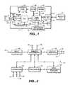
- FIG. 1is a block diagram illustration of a camera or other video acquisition device in which the techniques of the present invention may be implemented;
- FIG. 2is a block diagram of a portion of the electronic processing system of the device of FIG. 1 ;
- FIG. 3is a functional flow diagram showing motion stabilization and compression processes carried out in the camera of FIGS. 1 and 2 , according to a first embodiment
- FIG. 4illustrates a technique of variably cropping an image frame to stabilize an image, as can be used in the process of FIG. 3 ;
- FIG. 5illustrates the relative timing to acquire, compensate and compress data of a sequence of image frames, according to the first embodiment
- FIG. 6is a functional flow diagram showing motion stabilization and compression processes carried out in the camera of FIGS. 1 and 2 , according to a second embodiment
- FIG. 7illustrates a specific processing example to acquire and compensate data for unwanted motion between a sequence of image frames, according to the second embodiment
- FIG. 8shows the operation of one component of the processing example of FIG. 7 , namely coarse motion estimation (LRME);
- FIG. 9illustrates image cropping used in the processing example of FIG. 7 .
- FIG. 10is a functional flow diagram showing motion stabilization and compression processes carried out in the camera of FIGS. 1 and 2 , according to a third embodiment.
- Video data acquired by a digital cameraare typically processed to compensate for imperfections of the camera and to generally improve the quality of the image obtainable from the data.
- the correction for any defective pixel photodetector elements of the sensoris one processing function that may be performed.
- This processingmay also include de-mosaicing the individual pixel data to superimpose data from spatially separate monochromatic pixel detectors of the sensor to render superimposed multi-colored pixels in the image data. This de-mosaicing then makes it desirable to process the data to enhance and smooth edges of the image. Compensation of the image data for noise and variations of the camera optical system across the image and for variations among the sensor photodetectors may also be performed.
- Other processingtypically includes one or more of gamma correction, contrast stretching, chrominance filtering and the like.
- the processed dataare then usually compressed by use of a commercially available algorithm before storage in a non-volatile medium.
- Such data processingmay be performed in a personal computer on raw image data earlier acquired by the camera, may be performed in the camera itself or some of the processing done in the camera and other of the processing done later in a personal computer.
- This processingmay also include compensation for the effects of unwanted shake or jitter of the camera during the acquisition of a series of image frames that form a moving image. Compensation for such jitter to stabilize the series of image frames is the principle subject of the following description, particularly when combined with data compression.
- This processingis preferably done within the hand-held camera so that compensated video data is stored in a non-volatile memory associated with the camera any may thus be viewed directly, but this processing can alternatively be performed during post-processing the camera data in a personal computer or the like.
- FIG. 1such a camera is schematically shown to include a case 11 , an imaging optical system 13 , user controls and indicators 15 that generate and receive control signals 17 , a video input-output receptacle 19 with internal electrical connections 21 , and a card slot 23 , with internal electrical connections 25 .
- a non-volatile memory card 27is removably inserted into the card slot 23 . Data of images captured by the camera may be stored on the memory card 27 or in an internal non-volatile memory (not shown). Image data may also be outputted to another video device through the receptacle 19 .
- the memory card 27can be a commercially available semiconductor flash electrically erasable and programmable read-only-memory (EEPROM), small removable rotating magnetic disk or other non-volatile memory to which video data can be programmed by the camera. Alternatively, particularly when the camera is taking movies of thirty image frames per second or the like, larger capacity storage media can be used instead, such as magnetic tape or a writable optical disk.
- EEPROMelectrically erasable and programmable read-only-memory
- small removable rotating magnetic diskor other non-volatile memory to which video data can be programmed by the camera.
- larger capacity storage mediacan be used instead, such as magnetic tape or a writable optical disk.
- the optical system 13can be a single lens, as shown, but will normally be a set of lenses.
- An image 29 of a scene 31is formed in visible optical radiation through a shutter 33 onto a two-dimensional surface of an image sensor 35 .
- An electrical output 37 of the sensorcarries an analog signal resulting from scanning individual photo-detectors of the surface of the sensor 35 onto which the image 29 is projected.
- the sensor 35typically contains a large number of individual photo-detectors arranged in a two-dimensional array of rows and columns to detect individual pixels of the image 29 .
- Signals proportional to the intensity of light striking the individual photo-detectorsare obtained in the output 37 in time sequence, typically by scanning them in a raster pattern, where the rows of photo-detectors are scanned one at a time from left to right, beginning at the top row, to generate a frame of video data from which the image 29 may be reconstructed.
- the analog signal 37is applied to an analog-to-digital converter circuit chip 39 that generates digital data in circuits 41 of the image 29 .
- the signal in circuits 41is a sequence of individual blocks of digital data representing the intensity of light striking the individual photo-detectors of the sensor 35 .
- the photo-detectors of the sensor 35typically detect the intensity of the image pixel striking them in one of two or more individual color components. Early sensors detect only two separate colors of the image. Detection of three primary colors, such as red, green and blue (RGB) components, is common. Currently, image sensors that detect more than three color components are becoming available.
- RGBred, green and blue
- Processing of the video data in circuits 41 and control of the camera operationare provided, in this embodiment, by a single integrated circuit chip 43 .
- the circuit chip 43is connected to control and status lines 45 .
- the lines 45are, in turn, connected with the shutter 33 , sensor 29 , analog-to-digital converter 39 and other components of the camera to provide synchronous operation of them.
- a separate volatile random-access memory circuit chip 47is also connected to the processor chip 43 through lines 48 for temporary data storage.
- a separate non-volatile memory chip 49is connected to the processor chip 43 through lines 50 for storage of the processor program, calibration data and the like.
- the memory 49may be flash memory, which is re-programmable, or a memory that is programmable only once, such as a masked programmable read-only-memory (PROM) or an electrically programmable read-only-memory (EPROM).
- a usual clock circuit 51is provided within the camera for providing clock signals to the circuit chips and other components. Rather than a separate component, the clock circuit for the system may alternatively be included on the processor chip 43 .
- a general block diagram of the processor chip 43including portions that stabilize and compress image data, is given in FIG. 2 .
- a processor 51which may be general purpose or dedicated to the tasks herein, performs calculations on the image data and controls operation of the camera, in response to firmware stored in the flash memory 49 ( FIG. 1 ).
- Digital data of successive image framesare received over lines 41 by an interface circuit 55 through input contacts on the chip 43 , and then communicated with other system components by connection through a memory management unit 57 .
- Video data of the successive image frames, after stabilization and compression,are outputted through an interface circuit 59 to lines 21 (to the input-output receptacle 19 of FIGS. 1) and 25 (to the flash memory card slot 23 of FIG. 1 ) that are connected to output contacts on the chip 43 .
- Interface circuits 61communicate between the lines 17 , 45 and 50 (see FIG. 1 ) and the processor 51 and memory management unit 57 .
- Circuits 63 of FIG. 2are included in this embodiment to perform at least some of the calculations necessary to compress the data of successive image frames before being output through the interface circuits 59 . This can be more efficient than employing the processor 51 to make the calculations under control of the firmware.
- An estimation of motion between successive image framesis part of a typical compression technique. In the current MPEG-4 algorithm, motion vectors are calculated for various blocks of two successive image frames to estimate motion of portions of the image between them. A circuit to make at least a portion of this block motion vector calculation is included within the compression calculation circuits 63 .
- An image block motion calculationmay also be included as part of an algorithm that compensates for unwanted jitter of the camera between acquisitions of successive image frames. Therefore, at least part of the block motion vectors used for jitter compensation are preferably also calculated by the circuits 63 , as described further below. Whatever calculations required for data compression and camera jitter compensation in addition to those made by the dedicated circuits 63 are then performed by the processor 51 under firmware control
- FIG. 3illustrates operation of the processor of FIG. 2 , according to one general embodiment, to stabilize a moving image and compress the stabilized image data.
- An input 101 to the processingincludes data of successive image frames derived from data acquired from the sensor 35 ( FIG. 1 ).
- data of two successive imagesare used by a compression encoder to generate compressed data of the current image frame at an output 112 .
- Motion estimate vectorsare calculated from various blocks of both images by a portion 105 of the encoder to provide data of motion of the current image with respect to the immediately preceding image. These motion vectors are then utilized by remaining portions 107 of the encoder to encode the current image.
- Data of the acquired image framesare compressed one at a time by a standard compression algorithm such as one that provides compressed data according to the MPEG-4 standard.
- motion stabilization processing 109that uses the image block motion estimation 105 of the encoder 103 . If the image motion processing 105 is implemented in software, duplication of software code to perform the same function as part of the motion stabilization processing 109 is eliminated. Similarly, if the block motion estimating 105 is implemented by the hardwired logic circuitry 63 as part of the processor 43 ( FIGS. 1 and 2 ), as is preferred, then the same motion processing takes place during both stabilization and compression by passing different video data through the circuitry on each occasion.
- the motion processing 105calculates estimates of movement of different blocks of an image between successive image frames. This is one way that compression algorithms estimate motion as part of the encoding, referred to as block matching. Others methods of motion estimation are gradient matching and phase correlation. What is needed for the motion stabilization processing 109 , however, is an estimate of an overall motion between successive image frames. Therefore, global processing 111 takes the motion estimate vectors calculated for an individual block of the image by processing 105 and generates a global motion estimate vector from them. The global motion vectors calculated for successive images are then used by the motion stabilization processing 109 . A statistical value of the block motion vectors between two image frames may be calculated to provide the global motion vector, which is an estimate of the overall motion of the image between successive frames. In a specific example, a mean or median value of the block motion vectors is calculated.
- a current image frame received at the input 101first has its block motion vectors calculated by 105 with respect to the immediately preceding image frame. Those vectors are then used by the processing 111 to calculate a global motion vector between the current and the immediately preceding image frames. The global motion vectors are then used by the processing 109 to stabilize the current image frame for any unwanted motion that has occurred in the image since the immediately preceding frame. An output of the processing 109 are data of the current image frame that has been motion stabilized.
- Block motion vectorsare again calculated by the processing 105 but this time between data of the current stabilized image and those of the immediately preceding stabilized image. Those vectors are then used by remaining compression processing 107 to compress the current motion stabilized image frame, then provided at an output 112 .
- the process of FIG. 3is repeated for each newly acquired image frame, the block motion vectors being calculated from data of the new image frame with respect to data of the immediately preceding acquired image frame.
- the resultis data at the output 112 of a succession of stabilized image frames that are compressed.
- This datamay be stored, such as on a non-volatile memory card when the processing takes place in a video acquisition device, may be transmitted, such as over the Internet, or the like.
- FIG. 4A preferred technique for stabilizing the image (processing 109 of FIG. 3 ) is illustrated in FIG. 4 .
- the image sensor 35( FIG. 1 ) is made large enough that it provides data of an image frame 113 that is larger than a desired resulting stabilized image frame 115 having a defined size.
- the acquired image frame 113is cropped to the size of the image frame 115 by defining horizontal and vertical coordinates of the stabilized image frame 115 according to the magnitude of the global image motion vector calculated for the image frame by the processing 111 .
- the image frame 115moves horizontally and vertically within the acquired image frame 113 . This is used to compensate for unwanted global motion between successive image frames.
- FIG. 5The combined image stabilization and compression of FIG. 3 is shown in FIG. 5 , wherein the pipelined nature of the processing becomes clear. That is, the process of stabilizing and compressing data of one image frame need not be completed before the process starts on the next image frame in sequence.
- the sequence of operations on data of each image frameis the same but shifted in time.
- data of image frame 1is acquired at 117 .
- This datawill usually be a series of values of primary colors (such as “RGB,” red, green and blue) obtained by scanning a two-dimensional pattern of single color photodetectors that typically forms the sensor 35 ( FIG. 1 ).
- RGBluminance and chrominance format
- the block motion vectors for the image frame 1are calculated, using YUV data of the immediately preceding image frame 0 and the processor of the compression encoder 103 ( FIG. 3 ).
- a global motion vectoris calculated from image frame 1 from those block motion vectors. The global motion vector is then used to stabilize the image frame 1 , at 125 , preferably in the manner described with respect to FIG. 4 .
- the next two steps 127 and 129compress data of the stabilized image frame.
- block motion vectorsare calculated for the stabilized image frame 1 , using data of the immediately preceding stabilized image frame 0 , by a second use of the processing circuit 105 ( FIG. 3 ), followed at 129 by the remaining compression encoding processing.
- the resultant outputis the data of the acquired image frame 1 that has been stabilized and compressed.
- a global motion vectoris calculated for a current image frame with respect to an immediately preceding acquired image frame.
- an earlier preceding image framemay be used, such as one occurring two, three or more image frames before the current one being stabilized.
- an image frame occurring after the current image framemay be used instead.
- multiple image framesmay be used in addition to the current image frame, such as one or more image frames before and one or more frames after the current frame, two or more image frames before or two or more frames after the current frame. Additionally, there may be no need to use data of the current image frame to calculate a global motion vector with respect to it.
- a first difference between this second and the first embodimentis an added initial pre-stabilization of the incoming image frame based upon the global motion vector calculated for the immediately preceding image frame.
- a second differenceis that the calculation of the global motion vector used to stabilize an image may be made in two stages. A coarse global motion vector is calculated from a low-resolution version of the image, and this coarse vector used to sort through the block motion vectors of the full resolution image to find the most relevant vectors for the purpose of motion stabilization. Only the fewer selected relevant block vectors then need to be considered when calculating the global motion vector from them.
- pre-stabilization 131 of the acquired image frameis accomplished by using a global motion vector calculated by the processing function 111 when stabilizing the immediately preceding image frame. Therefore, the pre-stabilization 131 is not based upon motion of the current image frame. Rather, it is based on the motion occurring between two earlier frames as a rough estimate of the motion that may have occurred in the current image frame. An estimate of the actual motion between the current image frame and the previous image frame is then calculated in the manner of the first embodiment described with respect to FIG. 3 . But the starting point is the pre-stabilized image frame data, which then reduces the amount of processing that is necessary in the final motion stabilization calculation 109 .
- low resolution versions of the incoming image frame dataare formed at 133 .
- One convenient way to do sois to represent data from a group of sensor pixels, such as a block of 8 ⁇ 8 pixels, as if the block was a single pixel. This may be done by an arithmetic process such as by averaging the values of all the pixels of the block to obtain the single value. This is done for each of the sensor's colors.
- Block motion vectorsare then calculated from the low-resolution image data output of 133 by passing data of two low-resolution image frames over a path through the block motion vector processing 105 .
- the resulting block motion vectors in a path 137are then processed at 111 to obtain a coarse global motion vector in a path 139 .
- That coarse (low resolution) global motion vectoris then used during the processing 105 to aid in selecting the blocks of input data of two successive image frames in a path 141 to be compared in the course of calculating fine block motion vectors.
- the resulting multiple block motion vectors, in a path 143are then processed at 111 to obtain a fine global motion vector in a path 145 . This vector is then used for the final image frame stabilization 109 .
- the stabilized image output of 109is then compressed by the encoder 103 , as described with respect to FIG. 3 .
- the dedicated processing 105 that calculates block motion vectors between two successive image framesis used three times in this embodiment.
- Low resolution image frame data in the path 135is input to it as part of a low resolution motion estimator (“LRME” output in line 137 ), high resolution image frame data in the path 141 as a high resolution motion estimator (“HRME” output in line 143 ) and then a final time when the stabilized image frame data are compressed by the encoder 103 .
- LRMElow resolution motion estimator
- HRMEhigh resolution motion estimator
- FIG. 7illustrates a very specific example of the image stabilization processing of FIG. 6 .
- the low resolution block motion vectors (LRME)are calculated by block motion estimation circuits within the compression encoder 63 ( FIG. 2 )
- the high resolution motion vectors (HRME)are calculated in this specific example by the processor 51 .
- bothcould instead be calculated by passing data through the dedicated circuits.
- image frame data S(n ⁇ 2) output from the sensorhas already been processed into a pre-stabilized image frame S V (n ⁇ 2) by use of a global motion vector earlier calculated between two prior successive acquired image frames.
- the data of the image frame S V ⁇ (n ⁇ 2)are converted into a YUV format.
- a low-resolution image D(n)is formed (also referred to as a dc-image) from the YUV image data V + (n ⁇ 1).
- Digital stabilizer processingthen occurs, using a low-resolution version D(n) of the current image and D(n ⁇ 1) of the immediately preceding image frame.
- the digital stabilizeralso receives data of the current full resolution image V i (n ⁇ 1), noted as input image V i + (n ⁇ 1), and that of the immediately preceding frame V i + (n ⁇ 2).
- the digital stabilizerperforms the coarse and fine stabilization processing discussed above with respect to FIG. 6 .
- At least the “Coarse ME (LRME)” processing block of the digital stabilizer of FIG. 7is preferably implemented by passing the data through the dedicated block motion vector calculating capability of the data compression encoder circuits 63 ( FIG. 2 ).
- the coarse global motion vector (GMV)is noted as G D (n+1).
- the global motion vector G(n+1) calculated for the current imagealso processes data of a subsequently received sensor image frame S(n+1) to provide data of a pre-stabilized cropped image S v ⁇ (n+1).
- This pre-stabilized image datathen goes through the same processing steps as described for the current sensor image S(n ⁇ 2).
- the processing (not shown) of each of the cropped versions S v ⁇ (n ⁇ 1) and S v ⁇ (n) of respective image frames S(n ⁇ 1) and S(n)was begun at different times and partially completed while the current cropped image S V ⁇ (n ⁇ 2) was subjected to the stabilization processing.
- This processing parallelism by pipeliningmaintains the performance of the image frame data processing at a high level.
- a sensor image S(n ⁇ 2)is received. Only sub-image S V ⁇ (n ⁇ 2) is used to generate a YUV-image.
- the YUV image frame V + (n ⁇ 1)is generated from S V ⁇ (n ⁇ 2) by the image processing unit (IPU) and the image scaler unit (ISU).
- IPUimage processing unit
- ISUimage scaler unit
- a dc-image D(n)is computed from V + (n ⁇ 1).
- the digital stabilizer algorithmcomputes the global motion vector G(n+1).
- a first image croppersets the location of S v ⁇ (n+1) within the sensor image S(n+1), and a second cropper positions the YUV-image V(n+1) within the larger image V + (n ⁇ 1).
- Motion estimation using the LRME unitis described next, with values taken for VGA size image as an example.
- the target dc-imageis divided into non-overlapped LRME blocks, with an 8 ⁇ 6 dc-pels (H ⁇ V) block size.
- a set of 10 ⁇ 10 LRME blocksare constructed.
- the search result for each target LRME_blockis the best coarse motion vector MV D .
- a search grid of 17 ⁇ 13is obtained from 17 search points in the horizontal and 13 points in the vertical axis.
- the target LRME_Block unitis always inside the search area.
- the representative (optimum) MV of that target unitis chosen as the one with the minimum SAD (sum absolute difference) between the target and the reference 8 ⁇ 6 pels.
- the next target macro-block (MB) location in the target dc-imageis taken from dc-pixel (x0+8, y0), in raster scan. Each dc-pel in the target dc-image is taken only once. Then, the next target units on the right are continued to be taken until the end of the dc-image: e.g., for VGA, 10 target units along one row. Then, the origin in the next strip will be at (x0, y0+6). There will be 10 targets units along each Column.
- FIG. 9illustrates the process, showing zoom factors in the sensor (S) and output image (V) domains.
- the horizontal and vertical scaling factors HorScale and VerScalescales the sensor image S (e.g., 2000 ⁇ 200 pels) into an image Vs with the required aspect ratio, which is expressed in the real pel domain:
- Vs _HorSizeHorScale* S _HorSize
- Vs _VerSizeVerScale* S _VerSize
- ZFsZFs*V ⁇ _HorSize
- Vs _VerSizeZFs*V ⁇ _VerSize
- the resolution in the sensor domainis 1/256 of pel.
- ZFv_mina minimum digital zoom factor
- a image frame S acquired from the sensoris cropped to a image frame S V ⁇ by the use of a global motion vector calculated from block motion vectors between two preceding image frames. Motion vectors from the current image frame are not used.
- thisis a pre-stabilization step that is followed in the second embodiment by further stabilization processing based upon the current image frame, there are some applications where this amount of stabilization may alone be sufficient.
- the image frame acquisition rateis high, such as' thirty frames-per-second or more, and relatively slow shaking of the video device is expected, such as at a frequency of three Hertz or less.
- a significant advantageis the greatly reduced amount of data processing that is required for motion stabilization.
- a compression encoder 151includes a section 153 that calculates block motion vectors of the individual image frames received by the encoder, preferably at least in part by a dedicated hardware circuit, and a section 155 that performs the remaining compression encoding calculations, as before.
- the compression encodingis also preceded by image motion stabilization processing 157 .
- the motion stabilization processinguses block motion vectors calculated by the section 153 for an image frame prior to the current frame that is being stabilized, with respect to yet an earlier frame.
- a global motion vector for the current frameis then calculated at 156 and used to stabilize the current image frame at 157 .
- block motion vectors calculated from two image frames acquired before the current image frame in order to compress the data of the most recent prior image frameare then also used to stabilize motion of the current image frame.
- the two prior image frameswill most commonly be the two immediately preceding in time the current image frame but that is not a requirement. Other pairs of prior image frames may be used instead. Since data of the current image frame are not used to calculate its motion vectors, the global motion vector can be available near the same time that data for the current image frame are acquired, or very shortly thereafter. This reduces the number of block motion vector calculations by at least one for each image frame.
Landscapes
- Engineering & Computer Science (AREA)
- Multimedia (AREA)
- Signal Processing (AREA)
- Studio Devices (AREA)
- Television Signal Processing For Recording (AREA)
- Compression Or Coding Systems Of Tv Signals (AREA)
Abstract
Description
- 1. Sensor image S(n+1), containing raw (2×2 pels in G, R, G, B format), is received and will be ready for further processing starting at t(n+1), where “pels” represent pixels.
- 2. YUV image V+(n+1) is constructed, by the Image Processing Unit (IPU), and the Image Scaler Unit (ISC) from SV−(n), a sub-image of the sensor image S(n).
- The V+ image is larger than the target image size (e.g., VGA). The extra area is used for cropping the target image at a new position that compensates for camera movements.
- The size of V+(V+_HorSize,V+_VerSize) is a parameter, with maximum value limited by the bandwidth of the DRAM image frame buffer memory (e.g., VGA size image the maximum size 672 (H)×504 (V) pels). The aspect ratio of the VGA image remains at 640/480=672/504.
- The IPU/ISC, takes a sub-section within the sensor image Sv−(n), then processes and converts it into a YUV-image V+. The position within the SV−(n) image frame is determined by the stabilizer coarse cropping output, which was the result of the last time frame [t(n−1), t(n)].
- The relation between the size of V+(V+_HorSize, V+_VerSize) and the raw sensor image (SV−_HorSize, SV−_VerSize) is depended on the digital zoom factor in the V domain ZFv, as well as, the horizontal and vertical scaling factors, HorScale and VerScale, which scales the sensor image (e.g., 2000×200 pels) into an image with the required aspect ratio.
V+_HorSize=ZFv*V−HorSize
V+VerSize=ZFv*V−_VerSize
where
V−_HorSize=HorScale*SV−_HorSize
V−_VerSize=VerScale*Sv−_VerSize
V− is the YUV-image before the digital zoom, with its horizontal and vertical size (V−_HorSize, V−_VerSize). Note, that SV− contains the sensor effective pixel area, as well as, the extra pixels at the edges of the sensor in each axis. In particular, when the digital zoom is one:
SV−_HorSize=SensorEffPelHor+SensorExtraPelHor
Sv−_VerSize=SensorEffPelVer+SensorExtraPelVer
where, (SensorEffPelHor, SensorEffPelVer) and (SensorExtraPelHor, SensorExtraPelVer) are the number of effective and extra pixels in the horizontal and vertical axis, respectively. The aspect ratios of the image frames V+ and V− are the same
- 3. A dc-image D(n+1) is generated from V+(n) by the compression unit (CMP)63 of
FIG. 1 .- Each 8×8 pels block is averaged and represented by a single dc-pixel. This 8:1 dc decimation will take only the central part of V+. For a VGA resolution, the VGA central part within V+ is taken. The size of D(n+1) is (640/8=80)×(480/8=60) dc-pels.
- 4. Low-resolution motion estimation (LRME) is performed on a target dc-image D(n), with D(n−1) as the reference dc-image.
- The result of the coarse LRME is a list of coarse MVDij(n+1), where i=1, 2, . . . M, j=1, 2, . . . , N. For a dc-image of 80 (H)×60 (V) dc-pels, and an LRME_block size of 8 (H)×6 (V), a list of M×N=10×10 block motion vectors (MVD) are generated for each dc-image, one optimal MVDfor each target unit.
- 5. A global coarse motion vector, GD(n+1) is computed by taking the median of all MVDvectors provided by the LRME unit.
GD(n+1)=median{MVDij(n+1), i=1, 2, . . . M, j=1, 2, . . . , N}- Median on odd number (K) of items in the list of vectors will return the item of sorted list that (K−1)/2 items are above it and (K−1)/2 below it.
- Median on even number (K) of items in the list of vectors will return the average of the K/2 and K1/+1 of the sorted list.
- 6. A subset of best L (e.g., L 8) MVDmotion vectors is then selected. The subset is the closest MVDvectors to the GDin the sense of dc-pel distance, as well as, taken from different parts of the image.
- First, all MVD; vectors are sorted by their distance from GD:
distance(MVDij,GD)=abs(MVDij(n+1)−GD(n+1))- Then, L vectors are taken as those with the minimum distance. Since they need to be taken from different parts of the image, the following condition is checked:
- When MVDijand MVD's are two MVD's in the subset L vectors, located at the target image at (i,j) and (m,n), respectively,
- then, they are separated at least Thr LRME_blocks
abs(i−m)<Thr,
abs(j−n)<Thr, - As a possible variation, LRME_block activity might help to select among two or more MVD motion vectors which have the same distance. Higher activity might increase the significance result of block matching in the fine resolution search. The LRME_block activity is calculated as the mean value of all block activity contained in the LRME block (48 blocks in 8×6 units). A single block activity is defined as the difference between the maximum and the minimum pel value in each 8×8 pel block.
- 7. The Fine GMV(n+1) is then calculated using V+(n−1) with V+(n−2) as target and reference images, respectively.
- A fine resolution search is performed around each MVDi, where i=1, 2, . . . , L, using the LRME unit. In this stage, each entry in the fine target LRME_B lock is referring to a pixel in the target frame V+(n−1). Its location (upper-left corner) is currently taken at the central of the coarse LRME Block. (As a variation, since MVD(m) is common for many 8×6 pels units since the LRME block is in the coarse stage, it is possible to choose that 8×6 unit with the highest block activity.)
- The search area for VGA size, which contains 24×18 pels of the reference image V+(n−2), is constructed from 8 pels to the left, 8 to the right, 6 pels up and 6 pels down from an origin pel. This constructs 17×13 search points. The minimal sum-absolute-difference (SAD) of these search points results in the m-th fine GMVi(n+1), where i=1, 2 . . . , L.
- The fine global motion vector G(n+1) is the median of the GMVi(n+1):
G(n+1)=median {GMVi(n+1),i=1, 2. . . , L}
- 8. Cropping V+(n+1) from V+(n−1): The cropping location of the VGA image V(n+1) from the V+(n−1) is determined by the global motion vector GD(n+1).
- 9. Set cropping location to SV−(n+1) from S(n+1): The new cropping position for the Sv−(n+1) in the sensor image S(n+1) is also based on the current fine global motion vector GD(n+1) (and might be based on forward predictions of previous GD(n−i), i=1, 2, . . . .)
- 10. V(n+1) is forwarded to the display, if one exists, and to the video compression encoder frame buffer employed by the image capture device for compression and storage.
Vs_HorSize=HorScale*S_HorSize
Vs_VerSize=VerScale*S_VerSize
In general, preparing the whole image Vs by the IPU & ISC (
V−_HorSize=HorScale*SV−_HorSize
V−13VerSize=VerScale*Sv−_VerSize
A digital Zoom factor ZFs is defined far the sensor image, as:
Vs_HorSize=ZFs*V−_HorSize
Vs_VerSize=ZFs*V−_VerSize
Note that it is possible to define the effective area by setting its origin (the upper-left coordinates) and the horizontal and vertical size. Its aspect ratio might not agree with the aspect ratio of the output frame V. In such cases, ZFs will be used in either horizontal or vertical axis, but not both.
The digital stabilizer uses a scale up factor ZFv to obtain a larger image V+from the V−image:
V+_HorSize=ZFv*V−_HorSize
V+_VerSizeZFv*V−_VerSize
Once the sensor structure (its size and required scaling for required aspect ratio) and the operating digital zoom factor ZFs are determined, the zoom factor ZFv for the digital stabilizer can be calculated as:
The quantity ZFv is used to convert cropping coordinates from V image pel domain into the V-domain:
V−(x,y)=V+(x,y)/ZFv
The resolution in the sensor domain is 1/256 of pel.
The use of a minimum digital zoom factor (ZFv_min) will now be described. For proper operation of the digital stabilizer in maximum zoom out, a minimum margin should be left within the sensor image for motion compensation. An example margin is about +/−50 pels in each edge of the output image domain:
(Vs_HorSize−V−_HorSize)*ZFv>=2*50
(Vs_VerSize−V−_VerSize)*ZFv>=2*50
The lower limit of the operating digital zoom factor (ZFs_min) is given by:
ZFs_min=max(1+100/V+_HorSize,1+100/V+_VerSize)
Therefore, the operating digital zoom factor should maintain the condition:
ZFs>=ZFs_min
The following example is given for a VGA sensor:
(Vs_HorSize, Vs_VerSize)(640, 480) pels
(V+_HorSize, V+_VerSize)=(672, 504) pels
ZFs_min=max(1+100/672,1+100/504)=max (1.15,1.20)=1.20, and
(V−_HorSize_max,V−_VerSize_max)=(Vs_HorSize,Vs_VerSize)/ZFs_min=(533,400) pels.
Since ZFs>=ZFs_min is desired, ZFs=ZFs_min=1.20 is selected. Then:
ZFv=ZFs*V+HorSize/Vs_HorSize=1.20*672/640=
=ZFs*V+_VerSize/Vs_VerSize=1.20*504/480=1.26
(Vs_HorSize−V−_HorSize)*ZFv=(640−533)*1.26=134 pels
(Vs_VerSize−V−_VerSize)*ZFv=(480−400)*1.26=100 pels
By this, an effective margin greater than 100 pels has been achieved.
Third Embodiment of Video Stabilization and Compression
Claims (8)
Priority Applications (1)
| Application Number | Priority Date | Filing Date | Title |
|---|---|---|---|
| US12/767,753US8289401B2 (en) | 2004-07-21 | 2010-04-26 | Processing of video data to compensate for unintended camera motion between acquired image frames |
Applications Claiming Priority (2)
| Application Number | Priority Date | Filing Date | Title |
|---|---|---|---|
| US10/897,186US7705884B2 (en) | 2004-07-21 | 2004-07-21 | Processing of video data to compensate for unintended camera motion between acquired image frames |
| US12/767,753US8289401B2 (en) | 2004-07-21 | 2010-04-26 | Processing of video data to compensate for unintended camera motion between acquired image frames |
Related Parent Applications (1)
| Application Number | Title | Priority Date | Filing Date |
|---|---|---|---|
| US10/897,186ContinuationUS7705884B2 (en) | 2004-07-21 | 2004-07-21 | Processing of video data to compensate for unintended camera motion between acquired image frames |
Publications (2)
| Publication Number | Publication Date |
|---|---|
| US20100208084A1 US20100208084A1 (en) | 2010-08-19 |
| US8289401B2true US8289401B2 (en) | 2012-10-16 |
Family
ID=35064611
Family Applications (2)
| Application Number | Title | Priority Date | Filing Date |
|---|---|---|---|
| US10/897,186Expired - Fee RelatedUS7705884B2 (en) | 2004-07-21 | 2004-07-21 | Processing of video data to compensate for unintended camera motion between acquired image frames |
| US12/767,753Expired - Fee RelatedUS8289401B2 (en) | 2004-07-21 | 2010-04-26 | Processing of video data to compensate for unintended camera motion between acquired image frames |
Family Applications Before (1)
| Application Number | Title | Priority Date | Filing Date |
|---|---|---|---|
| US10/897,186Expired - Fee RelatedUS7705884B2 (en) | 2004-07-21 | 2004-07-21 | Processing of video data to compensate for unintended camera motion between acquired image frames |
Country Status (5)
| Country | Link |
|---|---|
| US (2) | US7705884B2 (en) |
| EP (1) | EP1769626A1 (en) |
| JP (1) | JP5057974B2 (en) |
| CN (2) | CN102227126A (en) |
| WO (1) | WO2006019484A1 (en) |
Cited By (5)
| Publication number | Priority date | Publication date | Assignee | Title |
|---|---|---|---|---|
| US20130142397A1 (en)* | 2010-01-04 | 2013-06-06 | Sagem Defense Securite | Global and Dense Motion Estimation |
| US20130170769A1 (en)* | 2010-02-05 | 2013-07-04 | Canon Kabushiki Kaisha | Image processing apparatus, image capturing apparatus, and method of controlling the same |
| US9762848B2 (en) | 2013-03-15 | 2017-09-12 | Google Inc. | Automatic adjustment of video orientation |
| US20170339345A1 (en)* | 2016-05-18 | 2017-11-23 | Realtek Singapore Private Limited | Image frame processing method |
| US9996894B2 (en) | 2016-05-18 | 2018-06-12 | Realtek Singapore Pte Ltd | Image processing device, video subsystem and video pipeline |
Families Citing this family (91)
| Publication number | Priority date | Publication date | Assignee | Title |
|---|---|---|---|---|
| GB0307307D0 (en)* | 2003-03-29 | 2003-05-07 | Atelier Vision Ltd | Image processing |
| US7705884B2 (en)* | 2004-07-21 | 2010-04-27 | Zoran Corporation | Processing of video data to compensate for unintended camera motion between acquired image frames |
| JP4389749B2 (en)* | 2004-10-15 | 2009-12-24 | 株式会社ニコン | Panning camera and video editing program |
| US7376894B2 (en)* | 2004-11-18 | 2008-05-20 | Microsoft Corporation | Vector path merging into gradient elements |
| JP4277216B2 (en) | 2005-01-13 | 2009-06-10 | ソニー株式会社 | Imaging apparatus and imaging result processing method |
| US7558405B2 (en)* | 2005-06-30 | 2009-07-07 | Nokia Corporation | Motion filtering for video stabilization |
| JP2009505476A (en)* | 2005-08-10 | 2009-02-05 | エヌエックスピー ビー ヴィ | Method and apparatus for digital image stabilization |
| US7801427B2 (en)* | 2005-09-12 | 2010-09-21 | Nokia Corporation | Adjustment of shooting parameters in dependence of motion in a scene |
| US7546026B2 (en)* | 2005-10-25 | 2009-06-09 | Zoran Corporation | Camera exposure optimization techniques that take camera and scene motion into account |
| EP1793344A1 (en)* | 2005-11-30 | 2007-06-06 | THOMSON Licensing | Method of emendation for attention trajectory in video content analysis |
| US8094959B2 (en)* | 2005-12-09 | 2012-01-10 | Seiko Epson Corporation | Efficient detection of camera shake |
| TWI296178B (en)* | 2005-12-12 | 2008-04-21 | Novatek Microelectronics Corp | Image vibration-compensating apparatus and the method thereof |
| US8116576B2 (en)* | 2006-03-03 | 2012-02-14 | Panasonic Corporation | Image processing method and image processing device for reconstructing a high-resolution picture from a captured low-resolution picture |
| US7840085B2 (en)* | 2006-04-06 | 2010-11-23 | Qualcomm Incorporated | Electronic video image stabilization |
| US7841967B1 (en) | 2006-04-26 | 2010-11-30 | Dp Technologies, Inc. | Method and apparatus for providing fitness coaching using a mobile device |
| TWI325124B (en)* | 2006-05-10 | 2010-05-21 | Realtek Semiconductor Corp | Motion detection method and related apparatus |
| FR2903200B1 (en)* | 2006-06-29 | 2008-12-19 | Thales Sa | HYBRID STABILIZATION OF IMAGES FOR VIDEO CAMERA |
| US8902154B1 (en) | 2006-07-11 | 2014-12-02 | Dp Technologies, Inc. | Method and apparatus for utilizing motion user interface |
| US7982770B1 (en) | 2006-09-08 | 2011-07-19 | Dp Technologies, Inc. | Method and apparatus to provide improved image quality in a camera |
| US7697836B2 (en)* | 2006-10-25 | 2010-04-13 | Zoran Corporation | Control of artificial lighting of a scene to reduce effects of motion in the scene on an image being acquired |
| JP2008124580A (en)* | 2006-11-08 | 2008-05-29 | Matsushita Electric Ind Co Ltd | Motion vector detection method, motion vector detection device, and imaging system |
| US20080112630A1 (en)* | 2006-11-09 | 2008-05-15 | Oscar Nestares | Digital video stabilization based on robust dominant motion estimation |
| FR2908585B1 (en)* | 2006-11-15 | 2008-12-26 | Canon Kk | METHOD AND DEVICE FOR TRANSMITTING VIDEO DATA. |
| US8620353B1 (en) | 2007-01-26 | 2013-12-31 | Dp Technologies, Inc. | Automatic sharing and publication of multimedia from a mobile device |
| US8949070B1 (en) | 2007-02-08 | 2015-02-03 | Dp Technologies, Inc. | Human activity monitoring device with activity identification |
| US8149911B1 (en)* | 2007-02-16 | 2012-04-03 | Maxim Integrated Products, Inc. | Method and/or apparatus for multiple pass digital image stabilization |
| US8923400B1 (en) | 2007-02-16 | 2014-12-30 | Geo Semiconductor Inc | Method and/or apparatus for multiple pass digital image stabilization |
| US7924316B2 (en)* | 2007-03-14 | 2011-04-12 | Aptina Imaging Corporation | Image feature identification and motion compensation apparatus, systems, and methods |
| US8189061B1 (en)* | 2007-03-21 | 2012-05-29 | Ambarella, Inc. | Digital still camera with multiple frames combined into a single frame for digital anti-shake/anti-blur |
| TWI367026B (en)* | 2007-03-28 | 2012-06-21 | Quanta Comp Inc | Method and apparatus for image stabilization |
| US7995097B2 (en)* | 2007-05-25 | 2011-08-09 | Zoran Corporation | Techniques of motion estimation when acquiring an image of a scene that may be illuminated with a time varying luminance |
| US8174555B2 (en) | 2007-05-30 | 2012-05-08 | Eastman Kodak Company | Portable video communication system |
| JP5159189B2 (en)* | 2007-06-29 | 2013-03-06 | キヤノン株式会社 | Image processing apparatus, imaging apparatus, image processing method, and program |
| TWI338264B (en)* | 2007-07-02 | 2011-03-01 | Asustek Comp Inc | Image processing method and electric device using the same |
| US8555282B1 (en) | 2007-07-27 | 2013-10-08 | Dp Technologies, Inc. | Optimizing preemptive operating system with motion sensing |
| CN101159126B (en)* | 2007-10-31 | 2012-01-25 | 康佳集团股份有限公司 | Method for stabilizing handhold equipment image and device |
| US7800652B2 (en)* | 2007-12-12 | 2010-09-21 | Cyberlink Corp. | Reducing video shaking |
| US8040382B2 (en)* | 2008-01-07 | 2011-10-18 | Dp Technologies, Inc. | Method and apparatus for improving photo image quality |
| US20090201380A1 (en)* | 2008-02-12 | 2009-08-13 | Decisive Analytics Corporation | Method and apparatus for streamlined wireless data transfer |
| US8482620B2 (en) | 2008-03-11 | 2013-07-09 | Csr Technology Inc. | Image enhancement based on multiple frames and motion estimation |
| US8488678B2 (en)* | 2008-04-01 | 2013-07-16 | Canon Kabushiki Kaisha | Moving image encoding apparatus and moving image encoding method |
| US8285344B2 (en) | 2008-05-21 | 2012-10-09 | DP Technlogies, Inc. | Method and apparatus for adjusting audio for a user environment |
| US8996332B2 (en) | 2008-06-24 | 2015-03-31 | Dp Technologies, Inc. | Program setting adjustments based on activity identification |
| US20100046624A1 (en)* | 2008-08-20 | 2010-02-25 | Texas Instruments Incorporated | Method and apparatus for translation motion stabilization |
| US20100054542A1 (en)* | 2008-09-03 | 2010-03-04 | Texas Instruments Incorporated | Processing video frames with the same content but with luminance variations across frames |
| US8872646B2 (en) | 2008-10-08 | 2014-10-28 | Dp Technologies, Inc. | Method and system for waking up a device due to motion |
| JP4631966B2 (en)* | 2008-12-22 | 2011-02-16 | ソニー株式会社 | Image processing apparatus, image processing method, and program |
| US8458105B2 (en)* | 2009-02-12 | 2013-06-04 | Decisive Analytics Corporation | Method and apparatus for analyzing and interrelating data |
| US20100235314A1 (en)* | 2009-02-12 | 2010-09-16 | Decisive Analytics Corporation | Method and apparatus for analyzing and interrelating video data |
| US20100208086A1 (en)* | 2009-02-19 | 2010-08-19 | Texas Instruments Incorporated | Reduced-memory video stabilization |
| US20100259612A1 (en)* | 2009-04-09 | 2010-10-14 | Lars Christian | Control Module For Video Surveillance Device |
| US8064759B1 (en) | 2009-04-15 | 2011-11-22 | Dp Technologies, Inc. | Method and apparatus for motion-state based image acquisition |
| US9529437B2 (en) | 2009-05-26 | 2016-12-27 | Dp Technologies, Inc. | Method and apparatus for a motion state aware device |
| US20110019018A1 (en)* | 2009-07-22 | 2011-01-27 | National Chung Cheng University | Image comprssion system in coordination with camera motion |
| US8897602B2 (en)* | 2009-07-22 | 2014-11-25 | Aptina Imaging Corporation | Imaging system with multiframe scaler |
| US20110150093A1 (en)* | 2009-12-22 | 2011-06-23 | Stephen Mangiat | Methods and apparatus for completion of video stabilization |
| US8531504B2 (en) | 2010-06-11 | 2013-09-10 | Intel Corporation | System and method for 3D video stabilization by fusing orientation sensor readings and image alignment estimates |
| US8488010B2 (en) | 2010-09-21 | 2013-07-16 | Hewlett-Packard Development Company, L.P. | Generating a stabilized video sequence based on motion sensor data |
| US9172960B1 (en) | 2010-09-23 | 2015-10-27 | Qualcomm Technologies, Inc. | Quantization based on statistics and threshold of luminanceand chrominance |
| KR101737087B1 (en) | 2010-11-12 | 2017-05-17 | 삼성전자주식회사 | Method and apparatus for video stabilization by compensating sigth direction of camera |
| TW201303745A (en)* | 2011-07-14 | 2013-01-16 | Novatek Microelectronics Corp | Motion detection method and display device |
| JP5865696B2 (en)* | 2011-12-22 | 2016-02-17 | 株式会社メガチップス | Image processing device |
| JP5917907B2 (en)* | 2011-12-22 | 2016-05-18 | 株式会社メガチップス | Image processing device |
| TWI491248B (en)* | 2011-12-30 | 2015-07-01 | Chung Shan Inst Of Science | Global motion vector estimation method |
| US8810666B2 (en)* | 2012-01-16 | 2014-08-19 | Google Inc. | Methods and systems for processing a video for stabilization using dynamic crop |
| US8743222B2 (en)* | 2012-02-14 | 2014-06-03 | Nokia Corporation | Method and apparatus for cropping and stabilization of video images |
| US9279983B1 (en)* | 2012-10-30 | 2016-03-08 | Google Inc. | Image cropping |
| US9282259B2 (en) | 2012-12-10 | 2016-03-08 | Fluke Corporation | Camera and method for thermal image noise reduction using post processing techniques |
| CN104349039B (en)* | 2013-07-31 | 2017-10-24 | 展讯通信(上海)有限公司 | Video anti-fluttering method and device |
| CN104144345B (en)* | 2013-09-18 | 2016-08-17 | 腾讯科技(深圳)有限公司 | Carry out real time imaging at mobile terminal and know method for distinguishing and this mobile terminal |
| TWI542201B (en)* | 2013-12-26 | 2016-07-11 | 智原科技股份有限公司 | Method and apparatus for reducing jitters of video frames |
| IL233684B (en) | 2014-07-17 | 2018-01-31 | Shamir Hanan | Stabilization and display of remote images |
| US10341561B2 (en)* | 2015-09-11 | 2019-07-02 | Facebook, Inc. | Distributed image stabilization |
| US10499070B2 (en) | 2015-09-11 | 2019-12-03 | Facebook, Inc. | Key frame placement for distributed video encoding |
| US10063872B2 (en) | 2015-09-11 | 2018-08-28 | Facebook, Inc. | Segment based encoding of video |
| US10602157B2 (en) | 2015-09-11 | 2020-03-24 | Facebook, Inc. | Variable bitrate control for distributed video encoding |
| US10375156B2 (en) | 2015-09-11 | 2019-08-06 | Facebook, Inc. | Using worker nodes in a distributed video encoding system |
| US10602153B2 (en) | 2015-09-11 | 2020-03-24 | Facebook, Inc. | Ultra-high video compression |
| US10506235B2 (en) | 2015-09-11 | 2019-12-10 | Facebook, Inc. | Distributed control of video encoding speeds |
| CN105282399B (en)* | 2015-10-21 | 2018-06-26 | 中国科学院自动化研究所 | Zero-lag electronic image stabilization method based on digital circuit and sparse point registration |
| CN107241544B (en)* | 2016-03-28 | 2019-11-26 | 展讯通信(天津)有限公司 | Video image stabilization method, device and camera shooting terminal |
| US10097765B2 (en)* | 2016-04-20 | 2018-10-09 | Samsung Electronics Co., Ltd. | Methodology and apparatus for generating high fidelity zoom for mobile video |
| JP7030446B2 (en)* | 2017-08-14 | 2022-03-07 | キヤノン株式会社 | Image shake correction device and its control method |
| US10341562B1 (en) | 2017-09-07 | 2019-07-02 | Gopro, Inc. | Systems and methods for translational motion correction |
| JP2019121941A (en)* | 2018-01-09 | 2019-07-22 | ソニーセミコンダクタソリューションズ株式会社 | Image processing apparatus and method, and image processing system |
| US10664977B2 (en) | 2018-02-28 | 2020-05-26 | General Electric Company | Apparatus and method for image-based control of imaging system parameters |
| US10863097B2 (en)* | 2018-08-21 | 2020-12-08 | Gopro, Inc. | Field of view adjustment |
| TWI749364B (en)* | 2019-09-06 | 2021-12-11 | 瑞昱半導體股份有限公司 | Motion detection method and motion detection system |
| CN114339102B (en)* | 2020-09-29 | 2023-06-02 | 华为技术有限公司 | Video recording method and equipment |
| CN114519690B (en)* | 2020-11-19 | 2025-05-09 | 京东方科技集团股份有限公司 | Image processing method and device, image detection method and system, and storage medium |
| US12262117B2 (en)* | 2022-09-21 | 2025-03-25 | Apple Inc. | Sensor cropped video image stabilization (VIS) |
Citations (31)
| Publication number | Priority date | Publication date | Assignee | Title |
|---|---|---|---|---|
| US4959725A (en) | 1988-07-13 | 1990-09-25 | Sony Corporation | Method and apparatus for processing camera an image produced by a video camera to correct for undesired motion of the video camera |
| US5253071A (en) | 1991-12-20 | 1993-10-12 | Sony Corporation Of America | Method and apparatus for stabilizing an image produced in a video camera |
| JPH05304648A (en) | 1992-04-27 | 1993-11-16 | Canon Inc | Boosting circuit and picture signal reader |
| JPH06225289A (en) | 1993-01-25 | 1994-08-12 | Matsushita Electric Ind Co Ltd | Video signal encoder |
| US5384595A (en) | 1990-04-19 | 1995-01-24 | Matsushita Electric Industrial Co., Ltd. | Motion detector and image stabilizing system |
| US5552831A (en) | 1992-07-03 | 1996-09-03 | Matsushita Electric Industrial Co., Ltd. | Digital video signal decoding apparatus and presumed motion vector calculating method |
| JPH09130748A (en) | 1995-08-30 | 1997-05-16 | Sony Corp | Image signal processing unit and recording/reproducing device |
| JPH1051787A (en) | 1996-08-01 | 1998-02-20 | Sharp Corp | Motion vector detection device |
| US5729295A (en) | 1994-12-27 | 1998-03-17 | Sharp Kabushiki Kaisha | Image sequence encoding device and area extracting device |
| US5748231A (en) | 1992-10-13 | 1998-05-05 | Samsung Electronics Co., Ltd. | Adaptive motion vector decision method and device for digital image stabilizer system |
| WO1999012355A1 (en) | 1997-08-29 | 1999-03-11 | Siemens Aktiengesellschaft | Method for compressing image information |
| US5926212A (en) | 1995-08-30 | 1999-07-20 | Sony Corporation | Image signal processing apparatus and recording/reproducing apparatus |
| US6343100B1 (en) | 1997-06-02 | 2002-01-29 | Sharp Kabushiki Kaisha | Motion-vector detecting device |
| GB2366113A (en) | 2000-06-28 | 2002-02-27 | Samsung Electronics Co Ltd | Correcting a digital image for camera shake |
| US6407777B1 (en) | 1997-10-09 | 2002-06-18 | Deluca Michael Joseph | Red-eye filter method and apparatus |
| US6535244B1 (en) | 1997-10-10 | 2003-03-18 | Samsung Electronics Co., Ltd. | Image stabilizing apparatus using bit-plane matching and image stabilizing method using the same |
| US6628711B1 (en) | 1999-07-02 | 2003-09-30 | Motorola, Inc. | Method and apparatus for compensating for jitter in a digital video image |
| US20040001147A1 (en) | 2002-06-19 | 2004-01-01 | Stmicroelectronics S.R.L. | Method of stabilizing an image sequence |
| US20040005084A1 (en) | 2001-06-26 | 2004-01-08 | Tetsujiro Kondo | Image processing apparatus and method, and image-capturing apparatus |
| US20040027454A1 (en) | 2002-06-19 | 2004-02-12 | Stmicroelectronics S.R.I. | Motion estimation method and stabilization method for an image sequence |
| US20040100560A1 (en) | 2002-11-22 | 2004-05-27 | Stavely Donald J. | Tracking digital zoom in a digital video camera |
| US20040201705A1 (en) | 2001-09-11 | 2004-10-14 | Chun-Huang Lin | Method for detecting movement of image sensors |
| US20050163348A1 (en) | 2004-01-23 | 2005-07-28 | Mei Chen | Stabilizing a sequence of image frames |
| US20050179784A1 (en) | 2004-02-13 | 2005-08-18 | Yingyong Qi | Adaptive image stabilization |
| US20050248661A1 (en) | 2004-05-10 | 2005-11-10 | Stanvely Donald J | Image-stabilization systems and methods |
| US20050275727A1 (en) | 2004-06-15 | 2005-12-15 | Shang-Hong Lai | Video stabilization method |
| US20060061658A1 (en) | 2002-12-13 | 2006-03-23 | Qinetiq Limited | Image stabilisation system and method |
| US20060152590A1 (en) | 2002-12-26 | 2006-07-13 | Mitsubishi Denki Kabushiki Kaisha | Image processor |
| US7158570B2 (en) | 2001-05-10 | 2007-01-02 | Sony Corporation | Motion picture encoding apparatus |
| US7218675B1 (en) | 1991-06-24 | 2007-05-15 | Canon Kabushiki Kaisha | Signal processing device |
| US7705884B2 (en)* | 2004-07-21 | 2010-04-27 | Zoran Corporation | Processing of video data to compensate for unintended camera motion between acquired image frames |
Family Cites Families (1)
| Publication number | Priority date | Publication date | Assignee | Title |
|---|---|---|---|---|
| JP3200859B2 (en)* | 1991-03-25 | 2001-08-20 | ソニー株式会社 | Camera shake correction circuit and method |
- 2004
- 2004-07-21USUS10/897,186patent/US7705884B2/ennot_activeExpired - Fee Related
- 2005
- 2005-06-15WOPCT/US2005/021336patent/WO2006019484A1/enactiveApplication Filing
- 2005-06-15CNCN2011101845694Apatent/CN102227126A/enactivePending
- 2005-06-15EPEP05766898Apatent/EP1769626A1/ennot_activeWithdrawn
- 2005-06-15CNCN2005800306209Apatent/CN101019418B/ennot_activeExpired - Fee Related
- 2005-06-15JPJP2007522507Apatent/JP5057974B2/ennot_activeExpired - Fee Related
- 2010
- 2010-04-26USUS12/767,753patent/US8289401B2/ennot_activeExpired - Fee Related
Patent Citations (33)
| Publication number | Priority date | Publication date | Assignee | Title |
|---|---|---|---|---|
| US4959725A (en) | 1988-07-13 | 1990-09-25 | Sony Corporation | Method and apparatus for processing camera an image produced by a video camera to correct for undesired motion of the video camera |
| US5384595A (en) | 1990-04-19 | 1995-01-24 | Matsushita Electric Industrial Co., Ltd. | Motion detector and image stabilizing system |
| US7218675B1 (en) | 1991-06-24 | 2007-05-15 | Canon Kabushiki Kaisha | Signal processing device |
| US5253071A (en) | 1991-12-20 | 1993-10-12 | Sony Corporation Of America | Method and apparatus for stabilizing an image produced in a video camera |
| JPH05304648A (en) | 1992-04-27 | 1993-11-16 | Canon Inc | Boosting circuit and picture signal reader |
| US5552831A (en) | 1992-07-03 | 1996-09-03 | Matsushita Electric Industrial Co., Ltd. | Digital video signal decoding apparatus and presumed motion vector calculating method |
| US5748231A (en) | 1992-10-13 | 1998-05-05 | Samsung Electronics Co., Ltd. | Adaptive motion vector decision method and device for digital image stabilizer system |
| JPH06225289A (en) | 1993-01-25 | 1994-08-12 | Matsushita Electric Ind Co Ltd | Video signal encoder |
| US5729295A (en) | 1994-12-27 | 1998-03-17 | Sharp Kabushiki Kaisha | Image sequence encoding device and area extracting device |
| US5926212A (en) | 1995-08-30 | 1999-07-20 | Sony Corporation | Image signal processing apparatus and recording/reproducing apparatus |
| JPH09130748A (en) | 1995-08-30 | 1997-05-16 | Sony Corp | Image signal processing unit and recording/reproducing device |
| JPH1051787A (en) | 1996-08-01 | 1998-02-20 | Sharp Corp | Motion vector detection device |
| US6343100B1 (en) | 1997-06-02 | 2002-01-29 | Sharp Kabushiki Kaisha | Motion-vector detecting device |
| WO1999012355A1 (en) | 1997-08-29 | 1999-03-11 | Siemens Aktiengesellschaft | Method for compressing image information |
| US6407777B1 (en) | 1997-10-09 | 2002-06-18 | Deluca Michael Joseph | Red-eye filter method and apparatus |
| US6535244B1 (en) | 1997-10-10 | 2003-03-18 | Samsung Electronics Co., Ltd. | Image stabilizing apparatus using bit-plane matching and image stabilizing method using the same |
| US6628711B1 (en) | 1999-07-02 | 2003-09-30 | Motorola, Inc. | Method and apparatus for compensating for jitter in a digital video image |
| GB2366113A (en) | 2000-06-28 | 2002-02-27 | Samsung Electronics Co Ltd | Correcting a digital image for camera shake |
| US20020118761A1 (en) | 2000-06-28 | 2002-08-29 | Samsung Electronics Co., Ltd. | Decoder having digital image stabilization function and digital image stabilization method |
| US7158570B2 (en) | 2001-05-10 | 2007-01-02 | Sony Corporation | Motion picture encoding apparatus |
| US20040005084A1 (en) | 2001-06-26 | 2004-01-08 | Tetsujiro Kondo | Image processing apparatus and method, and image-capturing apparatus |
| US20040201705A1 (en) | 2001-09-11 | 2004-10-14 | Chun-Huang Lin | Method for detecting movement of image sensors |
| US7151561B2 (en) | 2001-09-11 | 2006-12-19 | Pixart Imaging Inc | Method for detecting movement of image sensors |
| US20040001147A1 (en) | 2002-06-19 | 2004-01-01 | Stmicroelectronics S.R.L. | Method of stabilizing an image sequence |
| US20040027454A1 (en) | 2002-06-19 | 2004-02-12 | Stmicroelectronics S.R.I. | Motion estimation method and stabilization method for an image sequence |
| US20040100560A1 (en) | 2002-11-22 | 2004-05-27 | Stavely Donald J. | Tracking digital zoom in a digital video camera |
| US20060061658A1 (en) | 2002-12-13 | 2006-03-23 | Qinetiq Limited | Image stabilisation system and method |
| US20060152590A1 (en) | 2002-12-26 | 2006-07-13 | Mitsubishi Denki Kabushiki Kaisha | Image processor |
| US20050163348A1 (en) | 2004-01-23 | 2005-07-28 | Mei Chen | Stabilizing a sequence of image frames |
| US20050179784A1 (en) | 2004-02-13 | 2005-08-18 | Yingyong Qi | Adaptive image stabilization |
| US20050248661A1 (en) | 2004-05-10 | 2005-11-10 | Stanvely Donald J | Image-stabilization systems and methods |
| US20050275727A1 (en) | 2004-06-15 | 2005-12-15 | Shang-Hong Lai | Video stabilization method |
| US7705884B2 (en)* | 2004-07-21 | 2010-04-27 | Zoran Corporation | Processing of video data to compensate for unintended camera motion between acquired image frames |
Non-Patent Citations (2)
| Title |
|---|
| EPO, "Office Action" corresponding European Patent Application No. 05 766 898.0 on Sep. 18, 2007, 5 pages. |
| EPO/ISA, "Notification of Transmittal of the International Search Report and the Written Opinion of the International Searching Authority, or the Declaation," mailed in related International Application No. PCT/US2005/021336 on Nov. 3, 2005, 10 pages. |
Cited By (10)
| Publication number | Priority date | Publication date | Assignee | Title |
|---|---|---|---|---|
| US20130142397A1 (en)* | 2010-01-04 | 2013-06-06 | Sagem Defense Securite | Global and Dense Motion Estimation |
| US8873809B2 (en)* | 2010-01-04 | 2014-10-28 | Sagem Defense Securite | Global and dense motion estimation |
| US20130170769A1 (en)* | 2010-02-05 | 2013-07-04 | Canon Kabushiki Kaisha | Image processing apparatus, image capturing apparatus, and method of controlling the same |
| US8837865B2 (en)* | 2010-02-05 | 2014-09-16 | Canon Kabushiki Kaisha | Image processing apparatus, image capturing apparatus, and method of controlling the same |
| US9762848B2 (en) | 2013-03-15 | 2017-09-12 | Google Inc. | Automatic adjustment of video orientation |
| US10469797B2 (en) | 2013-03-15 | 2019-11-05 | Google Llc | Automatic adjustment of video orientation |
| US10887543B2 (en) | 2013-03-15 | 2021-01-05 | Google Llc | Automatic adjustment of video orientation |
| US20170339345A1 (en)* | 2016-05-18 | 2017-11-23 | Realtek Singapore Private Limited | Image frame processing method |
| US9967465B2 (en)* | 2016-05-18 | 2018-05-08 | Realtek Singapore Pte Ltd | Image frame processing method |
| US9996894B2 (en) | 2016-05-18 | 2018-06-12 | Realtek Singapore Pte Ltd | Image processing device, video subsystem and video pipeline |
Also Published As
| Publication number | Publication date |
|---|---|
| CN102227126A (en) | 2011-10-26 |
| EP1769626A1 (en) | 2007-04-04 |
| CN101019418B (en) | 2011-08-24 |
| JP5057974B2 (en) | 2012-10-24 |
| US7705884B2 (en) | 2010-04-27 |
| WO2006019484A1 (en) | 2006-02-23 |
| US20100208084A1 (en) | 2010-08-19 |
| CN101019418A (en) | 2007-08-15 |
| JP2008507899A (en) | 2008-03-13 |
| US20060017814A1 (en) | 2006-01-26 |
Similar Documents
| Publication | Publication Date | Title |
|---|---|---|
| US8289401B2 (en) | Processing of video data to compensate for unintended camera motion between acquired image frames | |
| US8749646B2 (en) | Image processing apparatus, imaging apparatus, solid-state imaging device, image processing method and program | |
| US7903156B2 (en) | Image processing device, image processing method, computer program, recording medium storing the computer program, frame-to-frame motion computing method, and image processing method | |
| US7646891B2 (en) | Image processor | |
| US8896712B2 (en) | Determining and correcting for imaging device motion during an exposure | |
| US8248495B2 (en) | Image picking-up processing device, image picking-up device, image processing method and computer program | |
| US8072511B2 (en) | Noise reduction processing apparatus, noise reduction processing method, and image sensing apparatus | |
| US9055217B2 (en) | Image compositing apparatus, image compositing method and program recording device | |
| US20100208086A1 (en) | Reduced-memory video stabilization | |
| US20120162449A1 (en) | Digital image stabilization device and method | |
| JP5002738B2 (en) | Image generation device | |
| US8542298B2 (en) | Image processing device and image processing method | |
| KR101109532B1 (en) | Recording medium on which the image capturing apparatus, image capturing method, and image capturing program are recorded | |
| US20100103192A1 (en) | Image Processing Device, Image Processing method And Electronic Apparatus | |
| US20140286593A1 (en) | Image processing device, image procesisng method, program,and imaging device | |
| US8723969B2 (en) | Compensating for undesirable camera shakes during video capture | |
| JP2010016580A (en) | Image processing apparatus and image processing method | |
| JP2003078808A (en) | Device and method for detecting motion vector, device and method for correcting camera shake and imaging apparatus | |
| US20130155272A1 (en) | Image processing device, imaging device, and image processing method | |
| JP5055571B2 (en) | Image processing apparatus, electronic camera, and image processing program | |
| JP5548023B2 (en) | Imaging apparatus and imaging method | |
| US20130147985A1 (en) | Image processing device, imaging device, and image processing method |
Legal Events
| Date | Code | Title | Description |
|---|---|---|---|
| AS | Assignment | Owner name:ZORAN CORPORATION, CALIFORNIA Free format text:ASSIGNMENT OF ASSIGNORS INTEREST;ASSIGNORS:PINTO, VICTOR;DVIR, ITSIK;SIGNING DATES FROM 20050112 TO 20050117;REEL/FRAME:025023/0352 | |
| AS | Assignment | Owner name:ZORAN MICROELECTRONICS LTD., ISRAEL Free format text:ASSIGNMENT OF ASSIGNORS INTEREST;ASSIGNOR:ZORAN CORPORATION;REEL/FRAME:026907/0184 Effective date:20110630 | |
| AS | Assignment | Owner name:ZORAN CORPORATION, CALIFORNIA Free format text:ASSIGNMENT OF ASSIGNORS INTEREST;ASSIGNOR:ZORAN MICROELECTRONICS LTD.;REEL/FRAME:027154/0957 Effective date:20111027 | |
| FEPP | Fee payment procedure | Free format text:PAYOR NUMBER ASSIGNED (ORIGINAL EVENT CODE: ASPN); ENTITY STATUS OF PATENT OWNER: LARGE ENTITY | |
| AS | Assignment | Owner name:CSR TECHNOLOGY INC., CALIFORNIA Free format text:ASSIGNMENT OF ASSIGNORS INTEREST;ASSIGNOR:ZORAN CORPORATION;REEL/FRAME:027550/0695 Effective date:20120101 | |
| STCF | Information on status: patent grant | Free format text:PATENTED CASE | |
| AS | Assignment | Owner name:QUALCOMM TECHNOLOGIES, INC., CALIFORNIA Free format text:ASSIGNMENT OF ASSIGNORS INTEREST;ASSIGNOR:CSR TECHNOLOGY INC.;REEL/FRAME:033134/0007 Effective date:20140608 | |
| FEPP | Fee payment procedure | Free format text:PAYOR NUMBER ASSIGNED (ORIGINAL EVENT CODE: ASPN); ENTITY STATUS OF PATENT OWNER: LARGE ENTITY Free format text:PAYER NUMBER DE-ASSIGNED (ORIGINAL EVENT CODE: RMPN); ENTITY STATUS OF PATENT OWNER: LARGE ENTITY | |
| AS | Assignment | Owner name:CSR TECHNOLOGY INC., CALIFORNIA Free format text:ASSIGNMENT OF ASSIGNORS INTEREST;ASSIGNOR:ZORAN CORPORATION;REEL/FRAME:036642/0395 Effective date:20150915 | |
| FPAY | Fee payment | Year of fee payment:4 | |
| AS | Assignment | Owner name:QUALCOMM INCORPORATED, CALIFORNIA Free format text:ASSIGNMENT OF ASSIGNORS INTEREST;ASSIGNOR:QUALCOMM TECHNOLOGIES, INC.;REEL/FRAME:041694/0336 Effective date:20170210 | |
| FEPP | Fee payment procedure | Free format text:MAINTENANCE FEE REMINDER MAILED (ORIGINAL EVENT CODE: REM.); ENTITY STATUS OF PATENT OWNER: LARGE ENTITY | |
| LAPS | Lapse for failure to pay maintenance fees | Free format text:PATENT EXPIRED FOR FAILURE TO PAY MAINTENANCE FEES (ORIGINAL EVENT CODE: EXP.); ENTITY STATUS OF PATENT OWNER: LARGE ENTITY | |
| STCH | Information on status: patent discontinuation | Free format text:PATENT EXPIRED DUE TO NONPAYMENT OF MAINTENANCE FEES UNDER 37 CFR 1.362 | |
| FP | Lapsed due to failure to pay maintenance fee | Effective date:20201016 |