US8289286B2 - Zooming keyboard/keypad - Google Patents
Zooming keyboard/keypadDownload PDFInfo
- Publication number
- US8289286B2 US8289286B2US12/340,180US34018008AUS8289286B2US 8289286 B2US8289286 B2US 8289286B2US 34018008 AUS34018008 AUS 34018008AUS 8289286 B2US8289286 B2US 8289286B2
- Authority
- US
- United States
- Prior art keywords
- display element
- touch screen
- display
- size
- location
- Prior art date
- Legal status (The legal status is an assumption and is not a legal conclusion. Google has not performed a legal analysis and makes no representation as to the accuracy of the status listed.)
- Expired - Fee Related, expires
Links
Images


Classifications
- G—PHYSICS
- G06—COMPUTING OR CALCULATING; COUNTING
- G06F—ELECTRIC DIGITAL DATA PROCESSING
- G06F3/00—Input arrangements for transferring data to be processed into a form capable of being handled by the computer; Output arrangements for transferring data from processing unit to output unit, e.g. interface arrangements
- G06F3/01—Input arrangements or combined input and output arrangements for interaction between user and computer
- G06F3/048—Interaction techniques based on graphical user interfaces [GUI]
- G06F3/0487—Interaction techniques based on graphical user interfaces [GUI] using specific features provided by the input device, e.g. functions controlled by the rotation of a mouse with dual sensing arrangements, or of the nature of the input device, e.g. tap gestures based on pressure sensed by a digitiser
- G06F3/0488—Interaction techniques based on graphical user interfaces [GUI] using specific features provided by the input device, e.g. functions controlled by the rotation of a mouse with dual sensing arrangements, or of the nature of the input device, e.g. tap gestures based on pressure sensed by a digitiser using a touch-screen or digitiser, e.g. input of commands through traced gestures
- G06F3/04886—Interaction techniques based on graphical user interfaces [GUI] using specific features provided by the input device, e.g. functions controlled by the rotation of a mouse with dual sensing arrangements, or of the nature of the input device, e.g. tap gestures based on pressure sensed by a digitiser using a touch-screen or digitiser, e.g. input of commands through traced gestures by partitioning the display area of the touch-screen or the surface of the digitising tablet into independently controllable areas, e.g. virtual keyboards or menus
Definitions
- Devicessuch as mobile communication devices (e.g., cell phones, personal digital assistants (PDAs), etc.), include touch sensitive input devices (e.g., touch sensitive interfaces or displays, touch screens, etc.).
- Touch screensare usually formed with either a resistive or capacitive film layer, located above a display, which is used to sense a touch of the user's finger or a stylus.
- Some touch screensenable the user to input information (e.g., text, numbers, etc.) via a keyboard or a keypad displayed on the touch screen.
- the size of a touch screenmay be limited due to the size of the device containing the touch screen. Smaller touch screens may display the keyboard or keypad with small keys arranged in close proximity to one another. The closely-arranged, small keys may be difficult to manipulate by the user. For example, the user's finger (e.g., which may be larger than such keys) may accidently select keys adjacent to a desired key, which may cause incorrect input to the device.
- FIG. 1depicts a diagram of an exemplary device in which systems and/or methods described herein may be implemented
- FIG. 2illustrates a diagram of exemplary components of the device depicted in FIG. 1 ;
- FIGS. 3A-3Ddepict diagrams of exemplary text entry operations capable of being performed by the device illustrated in FIG. 1 ;
- FIGS. 4A and 4Billustrate diagrams of exemplary application operations capable of being performed by the device depicted in FIG. 1 ;
- FIGS. 5A-5Cdepict diagrams of exemplary components of a display of the device illustrated in FIG. 1 ;
- FIGS. 6A and 6Bdepict diagrams of exemplary operations capable of being performed by the display illustrated in FIGS. 5A-5C ;
- FIGS. 7-10depict flow charts of an exemplary process for providing a zooming keypad/keyboard on a touch screen according to implementations described herein.
- Systems and/or methods described hereinmay provide a zooming keypad/keyboard on a touch screen of a device (e.g., a cell phone, a PDA, a personal computer, a laptop computer, a remote control, etc.).
- the systems and/or methodsmay detect a finger/stylus in contact with and/or adjacent to the touch screen of the device, may calculate a location on the touch screen that is associated with the detected finger/stylus, and may enlarge a display element (e.g., a key, an icon, etc.) associated with the location.
- the systems and/or methodsmay display the enlarged display element on the touch screen, and may display, on a portion of the touch screen, a character associated with the display element.
- the systems and/or methodsmay detect removal of the finger/stylus from the location on the touch screen, may receive, as an input, a character and/or an executable application associated with the display element, and may restore the display element to its original size.
- the term “user”is intended to be broadly interpreted to include a device or a user and/or owner of a device.
- the terms “keypad” and “keyboard”may be used interchangeably herein.
- the term “touch screen”is intended to be broadly interpreted to include a touch screen display, a touch sensitive input device, a touch sensitive interface, etc.
- the term “input object,” as used herein,is intended to be broadly interpreted to include a user's finger, a stylus, a pen, a pencil, etc.
- display elementis intended to be broadly interpreted to include a key (e.g., of a keypad or keyboard), an icon, a button, a menu, and/or any other mechanism capable of being displayed by a touch screen and selected by a user.
- a keye.g., of a keypad or keyboard
- icone.g., of a button, a menu
- any other mechanismcapable of being displayed by a touch screen and selected by a user.
- FIG. 1is a diagram of an exemplary device 100 in which systems and/or methods described herein may be implemented.
- Device 100may include a radiotelephone, a personal communications system (PCS) terminal (e.g., that may combine a cellular radiotelephone with data processing and data communications capabilities), a PDA (e.g., that can include a radiotelephone, a pager, Internet/intranet access, etc.), a remote control (e.g., for a television), a portable gaming system, a global positioning system (GPS) device, a printer, a facsimile machine, a pager, a camera (e.g., a film camera or a digital camera), a video camera (e.g., a camcorder), a calculator, binoculars, a telescope, a personal computer, a laptop computer, any other device capable of utilizing a touch screen display, a thread or process running on one of these devices, and/or an object executable by one of these devices.
- device 100may include a housing 110 , a display 120 , a speaker 130 , a microphone 140 , light detectors 150 , and/or light generators 160 .
- Housing 110may protect the components of device 100 from outside elements.
- Housing 110may include a structure configured to hold devices and components used in device 100 , and may be formed from a variety of materials.
- housing 110may be formed from plastic, metal, or a composite, and may be configured to support display 120 , speaker 130 , microphone 140 , light detectors 150 , and/or light generators 160 .
- Display 120may provide visual information to the user.
- display 120may display text input into device 100 , text, images, video, and/or graphics received from another device, and/or information regarding incoming or outgoing calls or text messages, emails, media, games, phone books, address books, the current time, etc.
- display 120may include a touch screen display that may be configured to receive a user input when the user touches (or comes in close proximity to) display 120 .
- the usermay provide an input to display 120 directly, such as via the user's finger, or via other devices, such as a stylus.
- User inputs received via display 120may be processed by components and/or devices operating in device 100 .
- the touch screen displaymay permit the user to interact with device 100 in order to cause device 100 to perform one or more operations. Further details of display 120 are provided below in connection with, for example, FIGS. 2-6B .
- Speaker 130may provide audible information to a user of device 100 .
- Speaker 130may be located in an upper portion of device 100 , and may function as an ear piece when a user is engaged in a communication session using device 100 .
- Speaker 130may also function as an output device for music and/or audio information associated with games and/or video images played on device 100 .
- Microphone 140may receive audible information from the user.
- Microphone 140may include a device that converts speech or other acoustic signals into electrical signals for use by device 100 .
- Microphone 140may be located proximate to a lower side of device 100 .
- Each of light detectors 150may include a device capable of detecting variations in light beams generated by light sources 160 .
- each of light detectors 150may include a camera (e.g., a charge coupled device (CCD) based camera, a complementary metal oxide semiconductor (CMOS) based camera), a photo-detector (e.g., a photo-diode, a photo-transistor, etc.), a photon detector (i.e., a detector where light energy may interact with electrons in the detector's material and may generate free electrons), a thermal detector (i.e., a detector that may respond to heat energy delivered by light), a radar sensor, etc.
- a camerae.g., a charge coupled device (CCD) based camera, a complementary metal oxide semiconductor (CMOS) based camera
- CMOScomplementary metal oxide semiconductor
- a photo-detectore.g., a photo-diode, a photo-transistor, etc.
- Photon detectorsmay further include photoconductive detectors (i.e., incoming light may produce free electrons which can carry electrical current so that the electrical conductivity of the detector material may change as a function of the intensity of the incident light), photovoltaic detectors (a voltage may be generated if optical energy strikes the device), photoemissive detectors (incident photons may release electrons from the surface of the detector material, and the free electrons may be collected in an external circuit), etc.
- photoconductive detectorsi.e., incoming light may produce free electrons which can carry electrical current so that the electrical conductivity of the detector material may change as a function of the intensity of the incident light
- photovoltaic detectorsa voltage may be generated if optical energy strikes the device
- photoemissive detectorsincident photons may release electrons from the surface of the detector material, and the free electrons may be collected in an external circuit
- Each of light generators 160may include a device configured to emit light in the form of pulses, beams, waves, etc.
- each of light generators 160may include one or more separate light emission sources (e.g., one or more light emitting diodes (LEDs), one or more microwave energy transmitters, etc.).
- Light generators 160may be positioned and configured to emit light beams across a surface of display 120 in order to create a light grid in a plane adjacent to the surface of display 120 . Interruption (or variation) of the light grid (e.g., via a user's finger and/or a stylus) may be detected by light detectors 150 , and may be used by device 100 to determine a position of the user's finger and/or the stylus on display 120 . Further details of light detectors 150 and light generators 160 are provided below in connection with, for example, FIGS. 5A-6B .
- device 100may contain fewer, different, differently arranged, or additional components than depicted in FIG. 1 .
- device 100may include may include one or more pressure sensors or a capacitive layer (e.g., arranged below display 120 ) that may detect a contact location of a finger and/or a stylus on the surface of display 120 .
- one or more components of device 100may perform one or more other tasks described as being performed by one or more other components of device 100 .
- FIG. 2illustrates a diagram of exemplary components of device 100 .
- device 100may include a processor 200 , memory 210 , a user interface 220 , a communication interface 230 , and/or an antenna assembly 240 .
- Processor 200may include one or more microprocessors, application-specific integrated circuits (ASICs), field-programmable gate arrays (FPGAs), or the like. Processor 200 may control operation of device 100 and its components. In one implementation, processor 200 may control operation of components of device 100 in a manner described herein.
- ASICsapplication-specific integrated circuits
- FPGAsfield-programmable gate arrays
- Memory 210may include a random access memory (RAM), a read-only memory (ROM), and/or another type of memory to store data and instructions that may be used by processor 200 .
- RAMrandom access memory
- ROMread-only memory
- Memory 210may include a random access memory (RAM), a read-only memory (ROM), and/or another type of memory to store data and instructions that may be used by processor 200 .
- User interface 220may include mechanisms for inputting information to device 100 and/or for outputting information from device 100 .
- input and output mechanismsmight include buttons (e.g., control buttons, keys of a keypad, a joystick, etc.) or a touch screen interface (e.g., display 120 ) to permit data and control commands to be input into device 100 ; a speaker (e.g., speaker 130 ) to receive electrical signals and output audio signals; a microphone (e.g., microphone 140 ) to receive audio signals and output electrical signals; a display (e.g., display 120 ) to output visual information (e.g., text input into device 100 ); a vibrator to cause device 100 to vibrate; a light generator (e.g., light generators 160 ) and a light detector (e.g., light detectors 150 ) to detect a position of a user's finger and/or a stylus on display 120 ; etc.
- buttonse.g., control buttons, keys of a keypad,
- Communication interface 230may include, for example, a transmitter that may convert baseband signals from processor 200 to radio frequency (RF) signals and/or a receiver that may convert RF signals to baseband signals.
- communication interface 230may include a transceiver to perform functions of both a transmitter and a receiver.
- Communication interface 230may connect to antenna assembly 240 for transmission and/or reception of the RF signals.
- Antenna assembly 240may include one or more antennas to transmit and/or receive RF signals over the air.
- Antenna assembly 240may, for example, receive RF signals from communication interface 230 and transmit them over the air, and receive RF signals over the air and provide them to communication interface 230 .
- communication interface 230may communicate with a network and/or devices connected to a network.
- device 100may perform certain operations described herein in response to processor 200 executing software instructions of an application contained in a computer-readable medium, such as memory 210 .
- a computer-readable mediummay be defined as a physical or logical memory device.
- the software instructionsmay be read into memory 210 from another computer-readable medium or from another device via communication interface 230 .
- the software instructions contained in memory 210may cause processor 200 to perform processes described herein.
- hardwired circuitrymay be used in place of or in combination with software instructions to implement processes described herein.
- implementations described hereinare not limited to any specific combination of hardware circuitry and software.
- FIG. 2shows exemplary components of device 100
- device 100may contain fewer, different, differently arranged, or additional components than depicted in FIG. 2
- one or more components of device 100may perform one or more other tasks described as being performed by one or more other components of device 100 .
- FIGS. 3A-3Ddepict diagrams of exemplary text entry operations 300 capable of being performed by device 100 .
- the operations described in connection with FIGS. 3A-3Dmay be performed by processor 200 ( FIG. 2 ).
- device 100may include display 120 .
- Display 120may include the features described above in connection with FIG. 1 .
- display 120may display one or more display elements (e.g., icons associated with executable applications, characters (e.g., numbers, letters, punctuation symbols, etc.), etc.).
- the display elementsmay include a touch screen input mechanism 310 (e.g., that includes multiple non-scaled keys 320 ), and display 120 may further display a touch screen display portion 330 .
- Touch screen input mechanism 310may include a QWERTY-like layout (e.g., a traditional configuration of typewriter or computer keyboard keys) of non-scaled keys 320 .
- Each of non-scaled keys 320may be associated with and may display a corresponding character (e.g., a corresponding QWERTY character).
- Non-scaled keys 320may be small and arranged in close proximity to one another, which may make non-scaled keys 320 difficult to manipulate with a user's finger and/or a stylus.
- touch screen input mechanism 310may include other display elements (e.g., icons associated with executable applications, a standard telephone keypad, numbers, etc.).
- Touch screen display portion 330may include a portion of display 120 that displays information entered via touch screen input mechanism 310 .
- touch screen display portion 330may provide secondary feedback (e.g., a visual feedback) associated with the information entered via touch screen input mechanism 310 .
- touch screen display portion 330may correspond to a window that displays text entered for an email, a short message service (SMS) or text message, a contact of an address book, etc.
- SMSshort message service
- a usermay manipulate touch screen input mechanism 310 (e.g., via an input object, such as a finger (e.g., a thumb, an index finger, a middle finger, a ring finger, or a pinkie finger) and/or a stylus 340 associated with the user)
- device 100may sense or detect finger/stylus 340 being in contact with and/or being adjacent to touch screen input mechanism 340 . Since finger/stylus 340 may be larger than or almost as large as non-scaled keys 320 , device 100 may reconfigure touch screen input mechanism 310 accordingly.
- device 100may calculate a location of display 120 (e.g., the touch screen) associated with the detected finger/stylus 340 , may enlarge one of non-scaled keys 320 (e.g., an enlarged key 350 ) associated with the location, and may display enlarged key 350 on display 120 .
- a location of display 120e.g., the touch screen
- non-scaled keys 320e.g., an enlarged key 350
- device 100may enlarge the “I” key and may display the enlarged “I” key.
- display 120may sense a magnitude of the applied pressure (e.g., via a pressure sensor associated with display 120 ), and may enlarge one of non-scaled keys 320 (e.g., enlarged key 350 ) associated with the location based on the magnitude of the applied pressure. For example, a larger applied pressure may cause device 100 to provide enlarged key 350 at a first size, and a smaller applied pressure may cause device 100 to provide enlarged key 350 at a second size smaller than the first size.
- device 100may partially enlarge one or more non-scaled keys 320 (e.g., a partially enlarged key 360 ) provided adjacent to enlarged key 350 , and may display partially enlarged key 360 (e.g., the “U,” “O,” “J,” and “K” keys) on display 120 .
- the enlarged sizes of the partially enlarged key(s)may decrease as a radial distance from enlarged key 350 increases.
- the enlarged sizes of the partially enlarged key(s)may decrease continuously, in discrete steps, exponentially, etc. as the radial distance from enlarged key 350 increases. Any of the above-mentioned decreasing methods may be set as a default by device 100 .
- a user of device 100may select the default and/or may change the default as desired.
- device 100may display (e.g., in touch screen display portion 330 ) a currently selected character 370 associated with enlarged key 350 .
- a currently selected character 370associated with enlarged key 350 .
- device 100may display an “i” in touch screen display portion 330 .
- currently selected character 370may not be input into device 100 and/or permanently displayed in touch screen display portion 330 unless finger/stylus 340 contacts display 120 (e.g., at enlarged key 350 ) and removes finger/stylus 340 from contact with display 120 .
- finger/stylus 340may move to another location of display 120 .
- Device 100may calculate a location of display 120 associated with the detected finger/stylus 340 , may generate enlarged key 350 associated with the location, and may display enlarged key 350 on display 120 .
- finger/stylus 340since finger/stylus 340 is provided over the “U” key, device 100 may enlarge the “U” key and may display the enlarged “U” key.
- Device 100may partially enlarge one or more keys (e.g., partially enlarged key 360 ) provided adjacent to enlarged key 350 , and may display partially enlarged key 360 (e.g., the “Y,” “I,” “H,” and “J” keys) on display 120 . As further shown in FIG. 3C , device 100 may display (e.g., in touch screen display portion 330 ) currently selected character 370 associated with enlarged key 350 . For example, since finger/stylus 340 is provided over the “U” key, device 100 may display a “u” in touch screen display portion 330 .
- keyse.g., partially enlarged key 360
- partially enlarged key 360e.g., the “Y,” “I,” “H,” and “J” keys
- FIG. 3Cdevice 100 may display (e.g., in touch screen display portion 330 ) currently selected character 370 associated with enlarged key 350 . For example, since finger/stylus 340 is provided over the “U” key, device 100 may display
- device 100may detect removal of finger/stylus 340 from enlarged key 350 . For example, as shown in FIG. 3D , finger/stylus 340 may be moved away from display 120 .
- Device 100may receive an input character 380 (e.g., the letter “u”) associated with enlarged key 350 (e.g., the “U” key), and may restore enlarged key 350 and partially enlarged key 360 to their original sizes. In other words, device 100 may reconfigure touch screen input mechanism 310 to its original configuration, as shown in FIG. 3A .
- FIGS. 3A-3Dshow exemplary text entry operations 300 associated with device 100
- device 100may perform fewer, different, or additional operations than depicted in FIGS. 3A-3D .
- FIGS. 4A and 4Billustrate diagrams of exemplary application operations 400 capable of being performed by device 100 .
- the operations described in connection with FIGS. 4A and 4Bmay be performed by processor 200 ( FIG. 2 ).
- device 100may include display 120 .
- Display 120may include the features described above in connection with FIG. 1 .
- display 120may display one or more display elements.
- the display elementsmay include icons (e.g., non-scaled icons 410 ) associated with executable applications (e.g., an icon for an email application, an icon for a telephone application, an icon for an Internet application, an icon for a music application, etc.) capable of being executed by device 100 .
- executable applicationse.g., an icon for an email application, an icon for a telephone application, an icon for an Internet application, an icon for a music application, etc.
- Each of non-scaled icons 410may display information associated with the executable application corresponding to each of non-scaled icons 410 .
- Non-scaled icons 410may be small and arranged in close proximity to one another, which may make non-scaled icons 410 difficult to manipulate with a user's finger and/or a stylus.
- device 100may sense or detect finger/stylus 340 being in contact with and/or being adjacent to display 120 . Since finger/stylus 340 may be larger than or almost as large as non-scaled icons 410 , device 100 may reconfigure non-scaled icons 410 accordingly. In one exemplary implementation, device 100 may calculate a location of display 120 associated with the detected finger/stylus 340 , may enlarge one of non-scaled icons 410 (e.g., an enlarged icon 420 ) associated with the location, and may display enlarged icon 420 on display 120 . For example, as shown in FIG. 4A , since finger/stylus 340 is provided over the “Phone” icon, device 100 may enlarge the “Phone” icon and may display the enlarged “Phone” icon.
- non-scaled icons 410e.g., an enlarged icon 420
- Device 100may partially enlarge one or more icons (e.g., a partially enlarged icon 430 ) provided adjacent to enlarged icon 420 , and may display partially enlarged icon 430 (e.g., the “Email” and “Internet” icons) on display 120 .
- the enlarged sizes of the partially enlarged icon(s)may decrease as a radial distance from enlarged icon 420 increases.
- the enlarged sizes of the partially enlarged icon(s)may decrease continuously, in discrete steps, exponentially, etc. as the radial distance from enlarged icon 420 increases. Any of the above-mentioned decreasing methods may be set as a default by device 100 .
- a user of device 100may select the default and/or may change the default as desired.
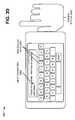
- device 100may detect removal of finger/stylus 340 from enlarged icon 420 , and may execute the application associated with enlarged icon 420 (e.g., the “Phone” application). As shown in FIG. 4B , execution of the “Phone” application may cause device 100 to display (e.g., via display 120 ) a standard telephone keypad that includes non-scaled keys (e.g., a non-scaled key 440 ) and enables the user to input a telephone number. As further shown in FIG.
- device 100may sense or detect finger/stylus 340 being in contact with and/or being adjacent to display 120 . Since finger/stylus 340 may be larger than or almost as large as non-scaled key 440 , device 100 may reconfigure the standard telephone keypad accordingly. In one exemplary implementation, device 100 may calculate a location of display 120 associated with the detected finger/stylus 340 , may enlarge one of the non-scaled keys (e.g., an enlarged key 450 ) associated with the location, and may display enlarged key 450 on display 120 . For example, as shown in FIG. 4B , since finger/stylus 340 is provided over the “4” key, device 100 may enlarge the “4” key and may display the enlarged “4” key.
- the non-scaled keyse.g., an enlarged key 450
- Device 100may partially enlarge one or more keys (e.g., a partially enlarged key 460 ) provided adjacent to enlarged key 450 , and may display partially enlarged key 460 (e.g., the “5” key) on display 120 .
- the enlarged sizes of the partially enlarged key(s)may decrease as a radial distance from enlarged key 450 increases.
- the enlarged sizes of the partially enlarged key(s)may decrease continuously, in discrete steps, exponentially, etc. as the radial distance from enlarged key 450 increases. Any of the above-mentioned decreasing methods may be set as a default by device 100 .
- a user of device 100may select the default and/or may change the default as desired.
- device 100may display a currently selected number 470 associated with enlarged key 450 .
- device 100may display a “4” in a portion of display 120 .
- currently selected number 470may not be input into device 100 and/or permanently displayed on display 120 unless finger/stylus 340 contacts display 120 (e.g., at enlarged key 450 ) and removes finger/stylus 340 from contact with display 120 .
- FIGS. 4A and 4Bshow exemplary text entry operations 300 associated with device 100
- device 100may perform fewer, different, or additional operations than depicted in FIGS. 4A and 4B .
- FIGS. 5A-5Cdepict diagrams of exemplary components of display 120 .
- display 120may include a light source 500 , a screen 510 , one of light detectors 150 , and one of light generators 160 .
- Light generator 150 and light detector 160may include the features described above in connection with, for example, FIG. 1 .
- Light source 500may include a device (e.g., a backlight) that provides backlighting to a lower surface of screen 510 in order to display information.
- light source 500may include one or more incandescent light bulbs, one or more light-emitting diodes (LEDs), an electroluminescent panel (ELP), one or more cold cathode fluorescent lamps (CCFL), one or more hot cathode fluorescent lamps (HCFL), etc. that illuminate portions of screen 510 .
- Incandescent light bulbsmay be used when very high brightness is desired. LEDs may be used in small, inexpensive lighting arrangements, and may include colored or white light.
- An ELPmay be used for larger lighting arrangements or when even lighting is desired, and may be either colored or white.
- CCFLsmay be used in large lighting arrangements and may be white in color.
- light source 500may employ one or more diffusers or light guides to provide even lighting from an uneven source.
- light source 500can include any color light source (e.g., yellow, green, blue, white, etc.) or any combination of colored/non-colored light sources. The light provided by light source 500 may also be used to provide front lighting to an upper surface of screen 510 that faces a user.
- Screen 510may include any device capable of providing visual information (e.g., text, images, video, incoming or outgoing calls, games, phone books, the current time, emails, etc.) to a user.
- screen 510may include a liquid crystal display (LCD), such as a thin film transistor (TFT) LCD, etc.
- LCDliquid crystal display
- TFTthin film transistor
- screen 510may include a plastic substrate that arranges TFT on a metal foil (rather than on glass), which may permit screen 510 to recover its original shape after being bent.
- Screen 510may include a color filter coated onto the plastic substrate, which may permit screen 510 to display color images.
- screen 510may include a monochrome, flexible LCD.
- screen 510may include any number of color and/or monochrome pixels.
- screen 510may include a passive-matrix structure or an active-matrix structure.
- each pixelmay be divided into three cells, or subpixels, which may be colored red, green, and blue by additional filters (e.g., pigment filters, dye filters, metal oxide filters, etc.). Each subpixel may be controlled independently to yield numerous possible colors for each pixel.
- each pixel of screen 510may include more or less than three subpixels of various colors other than red, green, and blue.
- light generator 160may generate a light beam 520 that may be received by light detector 150 .
- Light generator 160may be positioned and configured to emit light beams (e.g., light beam 520 ) across a surface of screen 510 in order to create a light grid in a plane adjacent to the surface of screen 510 .
- Such an arrangementmay enable device 100 to determine a position of finger/stylus 340 relative to screen 510 if finger/stylus 340 is provided close enough to the surface of screen 510 to interrupt light beam 520 .
- finger/stylus 340may interrupt light beam 520 (e.g., may cause an interrupted light beam 530 ) and may prevent light detector 150 from receiving interrupted light beam 530 .
- Thismay enable device 100 to determine a position of finger/stylus 340 relative to screen 510 in one direction (e.g., in a x-direction or in a y-direction).
- finger/stylus 340may interrupt certain light beams 520 generated in the x-direction and certain light beams 520 generated in the y-direction. Interruption (or variation) of the light grid (e.g., via finger/stylus 340 ) may be detected by light detectors 150 , and may be used by device 100 to determine a position of finger/stylus 340 relative to screen 510 (e.g., relative to display 120 ).
- device 100may calculate a first coordinate (e.g., an x-coordinate) associated with finger/stylus 340 based on information received from one of light detectors 150 , and may calculate a second coordinate (e.g., a y-coordinate) associated with finger/stylus 340 based on information received from the other one of light detectors 150 .
- Device 100may calculate a location of finger/stylus 340 relative to screen 510 based on the calculated first and second coordinates.
- FIGS. 5A-5Cshow exemplary components of display 120
- display 120may contain fewer, different, differently arranged, or additional components than depicted in FIGS. 5A-5C .
- one or more components of display 120may perform one or more other tasks described as being performed by one or more other components of display 120 .
- display 120may include one or more pressure sensors, arranged below screen 510 , that may detect contact (e.g., by finger/stylus 340 ) with screen 510 .
- the pressure sensorsmay be configured to determine the location of finger/stylus 340 relative to screen 510 (e.g., to display 120 ) in a same or similar manner that light detectors 150 and/or light generators 160 are used to determine the location of finger/stylus 340 .
- engagemente.g. via contact finger/stylus 340
- one or more pressure sensorsmay be used by device 100 to determine an accurate location of finger/stylus 340 relative to screen 510 .
- screen 510may include a capacitive touch screen that reacts to capacitance introduced by finger/stylus 340 .
- the capacitive touch screenmay include a first capacitive layer provided in a first direction (e.g., the x-direction) and a second capacitive layer provided in a second direction (e.g., the y-direction), which, together, provide a matrix structure.
- a first directione.g., the x-direction
- a second capacitive layerprovided in a second direction
- Such an arrangementmay enable device 100 to determine an x-coordinate and a y-coordinate (e.g., a location) associated with finger/stylus 340 relative to display 120 .
- FIGS. 6A and 6Bdepict diagrams of exemplary operations 600 capable of being performed by display 120 .
- Display 120may include the features described above in connection with, for example, FIGS. 5A-5C .
- light generators 160may generate light beams 520 in both the x-direction and the y-direction (e.g., to create a light grid).
- Finger/stylus 340may interrupt certain light beams 520 (e.g., interrupted light beams 530 ) generated in the x-direction and certain light beams 520 (e.g., interrupted light beams 530 ) generated in the y-direction.
- Interruption (or variation) of the light gridmay be detected by light detectors 150 , and may be used by device 100 to determine a location of finger/stylus 340 relative to display 120 .
- the location of finger/stylus 340 determined by light detectors 150may be used by device 100 to manipulate display 120 .
- the determined location of finger/stylus 340may correspond with an “I” key of a keyboard (e.g., touch screen input mechanism 310 ).
- Device 100may enlarge one of non-scaled keys 320 (e.g., enlarged key 350 ) associated with the location, and may display enlarged key 350 on display 120 .
- Device 100may also partially enlarge one or more non-scaled keys 320 (e.g., partially enlarged key 360 ) provided adjacent to enlarged key 350 , and may display partially enlarged key 360 (e.g., the “U,” “O,” “J,” and “K” keys) on display 120 .
- partially enlarged key 360e.g., the “U,” “O,” “J,” and “K” keys
- FIGS. 6A and 6Bshow exemplary operations 600 associated with display 120
- display 120may perform fewer, different, or additional operations than depicted in FIGS. 6A and 6B .
- FIGS. 7-10depict flow charts of an exemplary process 700 for providing a zooming keypad/keyboard on a touch screen according to implementations described herein.
- process 700may be performed by device 100 .
- some or all of process 700may be performed by another device or group of devices, including or excluding device 100 .
- process 700may begin with detection of a finger and/or a stylus in contact with or adjacent to a touch screen of a device (block 710 ), and calculating a location on the touch screen that is associated with the detected finger/stylus (block 720 ).
- device 100may sense or detect finger/stylus 340 being in contact with and/or being adjacent to touch screen input mechanism 340 . Since finger/stylus 340 may be larger than or almost as large as non-scaled keys 320 , device 100 may reconfigure touch screen input mechanism 310 accordingly.
- Device 100may calculate a location of display 120 (e.g., the touch screen) associated with the detected finger/stylus 340 .
- a display element associated with the locationmay be enlarged (block 730 ), the enlarged display element may be displayed on the touch screen (block 740 ), and a character associated with the display element may be displayed on a portion of the touch screen (block 750 ).
- device 100may enlarge one of non-scaled keys 320 (e.g., enlarged key 350 ) associated with the location, and may display enlarged key 350 on display 120 .
- device 100may enlarge the “I” key and may display the enlarged “I” key.
- Device 100may display (e.g., in touch screen display portion 330 ) currently selected character 370 associated with enlarged key 350 . If finger/stylus 340 is provided over the “I” key, device 100 may display an “i” in touch screen display portion 330 .
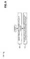
- removal of the finger/stylus from the location on the touch screenmay be detected (block 760 ), a character or an executable application associated with the display element may be received as an input (block 770 ), and the display element may be restored to its original size (block 780 ).
- a character or an executable application associated with the display elementmay be received as an input (block 770 )
- the display elementmay be restored to its original size (block 780 ).
- device 100may detect removal of finger/stylus 340 from enlarged key 350 .
- device 100may receive input character 380 (e.g., the letter “u”) associated with enlarged key 350 (e.g., the “U” key), and may restore enlarged key 350 and partially enlarged key 360 to their original sizes. In other words, device 100 may reconfigure touch screen input mechanism 310 to its original configuration.
- input character 380e.g., the letter “u”
- enlarged key 350e.g., the “U” key
- device 100may reconfigure touch screen input mechanism 310 to its original configuration.
- Process block 720may include the process blocks illustrated in FIG. 8 . As shown in FIG. 8 , process block 720 may include calculating a first finger/stylus coordinate based on information received from a first detector (block 800 ), calculating a second finger/stylus coordinate based on information received from a second detector (block 810 ), and calculating the location on the touch screen that is associated with the finger/stylus based on the first and second finger/stylus coordinates (block 820 ). For example, in implementations described above in connection with FIG.
- device 100may calculate a first coordinate (e.g., an x-coordinate) associated with finger/stylus 340 based on information received from one of light detectors 150 , and may calculate a second coordinate (e.g., a y-coordinate) associated with finger/stylus 340 based on information received from the other one of light detectors 150 .
- Device 100may calculate a location of finger/stylus 340 relative to screen 510 based on the calculated first and second coordinates.
- Process block 730may include the process blocks illustrated in FIG. 9 . As shown in FIG. 9 , process block 730 may include sensing a pressure of the finger/stylus at the location on the touch screen that is associated with the finger/stylus (block 900 ), and enlarging the display element associated with the location based on the sensed pressure ( 910 ). For example, in implementations described above in connection with FIG. 9
- display 120may sense a magnitude of the applied pressure (e.g., via a pressure sensor associated with display 120 ), and may enlarge one of non-scaled keys 320 (e.g., enlarged key 350 ) associated with the location based on the magnitude of the applied pressure.
- a larger applied pressuremay cause device 100 to provide enlarged key 350 at a first size
- a smaller applied pressuremay cause device 100 to provide enlarged key 350 at a second size smaller than the first size.
- process blocks 730 and 740may include the process blocks illustrated in FIG. 10 .
- process blocks 730 and 740may include enlarging the display element to a first size (block 1000 ), enlarging one or more other display elements, provided adjacent to the display element, to a second size smaller than the first size (block 1010 ), and displaying, on the touch screen, the display element enlarged to the first size and the one or more other display elements enlarged to a second size (block 1020 ).
- block 1000first size
- block 1010a second size smaller than the first size
- block 1020a second size
- device 100may partially enlarge one or more non-scaled keys 320 (e.g., partially enlarged key 360 ) provided adjacent to enlarged key 350 , and may display partially enlarged key 360 (e.g., the “U,” “O,” “J,” and “K” keys) on display 120 .
- the enlarged sizes of the partially enlarged key(s)may decrease as a radial distance from enlarged key 350 increases. In one example, the enlarged sizes of the partially enlarged key(s) may decrease continuously, in discrete steps, exponentially, etc. as the radial distance from enlarged key 350 increases.
- Systems and/or methods described hereinmay provide a zooming keypad/keyboard on a touch screen of a device.
- the systems and/or methodsmay detect a finger/stylus in contact with and/or adjacent to the touch screen of the device, may calculate a location on the touch screen that is associated with the detected finger/stylus, and may enlarge a display element (e.g., a key, an icon, etc.) associated with the location.
- the systems and/or methodsmay display the enlarged display element on the touch screen, and may display, on a portion of the touch screen, a character associated with the display element.
- the systems and/or methodsmay detect removal of the finger/stylus from the location on the touch screen, may receive, as an input, a character and/or an executable application associated with the display element, and may restore the display element to its original size.
- logicmay include hardware, such as an application specific integrated circuit or a field programmable gate array, or a combination of hardware and software.
Landscapes
- Engineering & Computer Science (AREA)
- General Engineering & Computer Science (AREA)
- Theoretical Computer Science (AREA)
- Human Computer Interaction (AREA)
- Physics & Mathematics (AREA)
- General Physics & Mathematics (AREA)
- User Interface Of Digital Computer (AREA)
Abstract
Description
Claims (25)
Priority Applications (1)
| Application Number | Priority Date | Filing Date | Title |
|---|---|---|---|
| US12/340,180US8289286B2 (en) | 2008-12-19 | 2008-12-19 | Zooming keyboard/keypad |
Applications Claiming Priority (1)
| Application Number | Priority Date | Filing Date | Title |
|---|---|---|---|
| US12/340,180US8289286B2 (en) | 2008-12-19 | 2008-12-19 | Zooming keyboard/keypad |
Publications (2)
| Publication Number | Publication Date |
|---|---|
| US20100156807A1 US20100156807A1 (en) | 2010-06-24 |
| US8289286B2true US8289286B2 (en) | 2012-10-16 |
Family
ID=42265281
Family Applications (1)
| Application Number | Title | Priority Date | Filing Date |
|---|---|---|---|
| US12/340,180Expired - Fee RelatedUS8289286B2 (en) | 2008-12-19 | 2008-12-19 | Zooming keyboard/keypad |
Country Status (1)
| Country | Link |
|---|---|
| US (1) | US8289286B2 (en) |
Cited By (12)
| Publication number | Priority date | Publication date | Assignee | Title |
|---|---|---|---|---|
| US20040175036A1 (en)* | 1997-12-22 | 2004-09-09 | Ricoh Company, Ltd. | Multimedia visualization and integration environment |
| US20090319935A1 (en)* | 2008-02-04 | 2009-12-24 | Nokia Corporation | Method and Apparatus for Signaling Neighbor Cell Transmission Frame Allocations |
| US20100066695A1 (en)* | 2008-09-12 | 2010-03-18 | Reiko Miyazaki | Information Processing Apparatus, Information Processing Method and Computer Program |
| US20110181535A1 (en)* | 2010-01-27 | 2011-07-28 | Kyocera Corporation | Portable electronic device and method of controlling device |
| US20110285646A1 (en)* | 2010-05-19 | 2011-11-24 | Hon Hai Precision Industry Co., Ltd. | Electronic device with touch pad |
| US20140139556A1 (en)* | 2012-11-22 | 2014-05-22 | Shanghai Powermo Information Tech. Co. Ltd. | Apparatus and method for displaying software keyboards thereof |
| US20140208263A1 (en)* | 2013-01-24 | 2014-07-24 | Victor Maklouf | System and method for dynamically displaying characters over a screen of a computerized mobile device |
| US20140247218A1 (en)* | 2013-03-04 | 2014-09-04 | International Business Machines Corporation | Modifying key size on a touch screen based on fingertip location |
| US20150012868A1 (en)* | 2013-07-08 | 2015-01-08 | Samsung Display Co., Ltd. | Method and apparatus to reduce display lag of soft keyboard presses |
| US20150293674A1 (en)* | 2011-08-15 | 2015-10-15 | Telefonaktiebolaget L M Ericsson (Publ) | Resizing selection zones on a touch sensitive display responsive to likelihood of selection |
| US9983715B2 (en) | 2012-12-17 | 2018-05-29 | Apple Inc. | Force detection in touch devices using piezoelectric sensors |
| CN108710465A (en)* | 2018-03-19 | 2018-10-26 | 西安艾润物联网技术服务有限责任公司 | License plate number input method virtual key display control method, storage medium and user terminal |
Families Citing this family (78)
| Publication number | Priority date | Publication date | Assignee | Title |
|---|---|---|---|---|
| DE102007051010A1 (en)* | 2007-10-25 | 2009-04-30 | Bayerische Motoren Werke Aktiengesellschaft | Method for displaying information |
| KR100976527B1 (en)* | 2008-10-14 | 2010-08-17 | 하이디스 테크놀로지 주식회사 | LCD with touch screen function using photoconductor |
| US20100171888A1 (en)* | 2009-01-05 | 2010-07-08 | Hipolito Saenz | Video frame recorder |
| JP2011018200A (en)* | 2009-07-09 | 2011-01-27 | Seiko Epson Corp | Information input apparatus and information input method |
| TWI492140B (en)* | 2009-08-28 | 2015-07-11 | Compal Electronics Inc | Method for keyboard input and assistant system thereof |
| US20110050575A1 (en)* | 2009-08-31 | 2011-03-03 | Motorola, Inc. | Method and apparatus for an adaptive touch screen display |
| JP5278259B2 (en)* | 2009-09-07 | 2013-09-04 | ソニー株式会社 | Input device, input method, and program |
| KR101623008B1 (en)* | 2009-10-23 | 2016-05-31 | 엘지전자 주식회사 | Mobile terminal |
| TWI420379B (en)* | 2009-12-09 | 2013-12-21 | Telepaq Technology Inc | Method for selecting functional icons on a touch screen |
| KR101319264B1 (en) | 2010-01-22 | 2013-10-18 | 전자부품연구원 | Method for providing UI according to multi touch pressure and electronic device using the same |
| GB201011687D0 (en)* | 2010-07-12 | 2010-08-25 | Faster Imaging As | User interactions |
| KR101786577B1 (en) | 2010-10-19 | 2017-11-15 | 삼성전자주식회사 | Method for Controlling Bidirectional Remote Controller and Bidirectional Remote Controller for implementing thereof |
| JP2012094008A (en)* | 2010-10-27 | 2012-05-17 | Kyocera Corp | Portable electronic equipment |
| US10146426B2 (en)* | 2010-11-09 | 2018-12-04 | Nokia Technologies Oy | Apparatus and method for user input for controlling displayed information |
| US8405627B2 (en)* | 2010-12-07 | 2013-03-26 | Sony Mobile Communications Ab | Touch input disambiguation |
| US9292131B2 (en)* | 2011-07-14 | 2016-03-22 | 3M Innovative Properties Company | Light guide for backlight |
| US9035912B2 (en)* | 2011-07-14 | 2015-05-19 | 3M Innovative Properties Company | Digitizer for multi-display system |
| US9035911B2 (en)* | 2011-07-14 | 2015-05-19 | 3M Innovative Properties Company | Digitizer using position-unique optical signals |
| US20130100334A1 (en)* | 2011-10-20 | 2013-04-25 | Broadcom Corporation | Method and System for an Adaptive Auto-Focus Algorithm |
| EP2624116B1 (en) | 2012-02-03 | 2017-09-06 | EchoStar Technologies L.L.C. | Display zoom controlled by proximity detection |
| US8812983B2 (en)* | 2012-02-17 | 2014-08-19 | Lenovo (Singapore) Pte. Ltd. | Automatic magnification and selection confirmation |
| JP2013235344A (en)* | 2012-05-07 | 2013-11-21 | Sony Computer Entertainment Inc | Input device, input control method, and input control program |
| WO2013169842A2 (en) | 2012-05-09 | 2013-11-14 | Yknots Industries Llc | Device, method, and graphical user interface for selecting object within a group of objects |
| WO2013169849A2 (en) | 2012-05-09 | 2013-11-14 | Industries Llc Yknots | Device, method, and graphical user interface for displaying user interface objects corresponding to an application |
| AU2013259630B2 (en) | 2012-05-09 | 2016-07-07 | Apple Inc. | Device, method, and graphical user interface for transitioning between display states in response to gesture |
| WO2013169851A2 (en) | 2012-05-09 | 2013-11-14 | Yknots Industries Llc | Device, method, and graphical user interface for facilitating user interaction with controls in a user interface |
| WO2013169843A1 (en) | 2012-05-09 | 2013-11-14 | Yknots Industries Llc | Device, method, and graphical user interface for manipulating framed graphical objects |
| CN108958550B (en) | 2012-05-09 | 2021-11-12 | 苹果公司 | Device, method and graphical user interface for displaying additional information in response to user contact |
| EP3410287B1 (en) | 2012-05-09 | 2022-08-17 | Apple Inc. | Device, method, and graphical user interface for selecting user interface objects |
| WO2013169875A2 (en)* | 2012-05-09 | 2013-11-14 | Yknots Industries Llc | Device, method, and graphical user interface for displaying content associated with a corresponding affordance |
| CN108241465B (en) | 2012-05-09 | 2021-03-09 | 苹果公司 | Method and apparatus for providing haptic feedback for operations performed in a user interface |
| WO2013169865A2 (en) | 2012-05-09 | 2013-11-14 | Yknots Industries Llc | Device, method, and graphical user interface for moving a user interface object based on an intensity of a press input |
| HK1208275A1 (en) | 2012-05-09 | 2016-02-26 | 苹果公司 | Device, method, and graphical user interface for moving and dropping a user interface object |
| EP2847662B1 (en) | 2012-05-09 | 2020-02-19 | Apple Inc. | Device, method, and graphical user interface for providing feedback for changing activation states of a user interface object |
| KR101913817B1 (en)* | 2012-08-29 | 2018-10-31 | 삼성전자주식회사 | Method and device for processing touch screen input |
| CN103677597A (en)* | 2012-09-10 | 2014-03-26 | 华为终端有限公司 | Terminal equipment and same-screen display method and system |
| US20140078065A1 (en)* | 2012-09-15 | 2014-03-20 | Ahmet Akkok | Predictive Keyboard With Suppressed Keys |
| US20140149932A1 (en)* | 2012-11-26 | 2014-05-29 | Nero Ag | System and method for providing a tapestry presentation |
| USD754161S1 (en) | 2012-11-26 | 2016-04-19 | Nero Ag | Device with a display screen with graphical user interface |
| CN105144057B (en) | 2012-12-29 | 2019-05-17 | 苹果公司 | For moving the equipment, method and graphic user interface of cursor according to the cosmetic variation of the control icon with simulation three-dimensional feature |
| CN105264479B (en) | 2012-12-29 | 2018-12-25 | 苹果公司 | Apparatus, method and graphical user interface for navigating a user interface hierarchy |
| WO2014105279A1 (en) | 2012-12-29 | 2014-07-03 | Yknots Industries Llc | Device, method, and graphical user interface for switching between user interfaces |
| KR102001332B1 (en) | 2012-12-29 | 2019-07-17 | 애플 인크. | Device, method, and graphical user interface for determining whether to scroll or select contents |
| US20140198081A1 (en)* | 2013-01-11 | 2014-07-17 | Research In Motion Limited | Image zoom control using stylus force sensing |
| CN103135930B (en)* | 2013-02-05 | 2017-04-05 | 深圳市金立通信设备有限公司 | A kind of touch screen control method and equipment |
| KR102118084B1 (en)* | 2013-03-22 | 2020-06-02 | 삼성전자주식회사 | Method and apparatus for displaying screen in device comprising a touch screen |
| CN104238926A (en)* | 2013-06-07 | 2014-12-24 | 中兴通讯股份有限公司 | Method and device for generating virtual screen of touch terminal, touch terminal and operating method thereof |
| GB2516029A (en)* | 2013-07-08 | 2015-01-14 | Ibm | Touchscreen keyboard |
| KR102201730B1 (en) | 2013-09-02 | 2021-01-12 | 엘지전자 주식회사 | Apparatus and Method for Display Device with Tactile feedback |
| JP2015066354A (en)* | 2013-09-30 | 2015-04-13 | オムロン株式会社 | Game machine |
| US20150091815A1 (en)* | 2013-10-01 | 2015-04-02 | Avaya Inc. | Method and Apparatus to Support Visually Impaired Users of Touchscreen Based User Interfaces |
| AU2015100011B4 (en)* | 2014-01-13 | 2015-07-16 | Apple Inc. | Temperature compensating transparent force sensor |
| DE102014203462A1 (en)* | 2014-02-26 | 2015-08-27 | Bayerische Motoren Werke Aktiengesellschaft | A method, apparatus, system, computer program and computer program product for operating a touch-sensitive screen |
| EP3147747A1 (en) | 2014-06-27 | 2017-03-29 | Apple Inc. | Manipulation of calendar application in device with touch screen |
| TWI647608B (en) | 2014-07-21 | 2019-01-11 | 美商蘋果公司 | Remote user interface |
| KR102511376B1 (en) | 2014-08-02 | 2023-03-17 | 애플 인크. | Context-specific user interfaces |
| CN115665320B (en) | 2014-09-02 | 2024-10-11 | 苹果公司 | Electronic device, storage medium, and method for operating an electronic device |
| US10048757B2 (en) | 2015-03-08 | 2018-08-14 | Apple Inc. | Devices and methods for controlling media presentation |
| US10095396B2 (en) | 2015-03-08 | 2018-10-09 | Apple Inc. | Devices, methods, and graphical user interfaces for interacting with a control object while dragging another object |
| US9632664B2 (en) | 2015-03-08 | 2017-04-25 | Apple Inc. | Devices, methods, and graphical user interfaces for manipulating user interface objects with visual and/or haptic feedback |
| JP6274134B2 (en)* | 2015-03-10 | 2018-02-07 | 京セラドキュメントソリューションズ株式会社 | Display input device and image forming apparatus having the same |
| US9639184B2 (en) | 2015-03-19 | 2017-05-02 | Apple Inc. | Touch input cursor manipulation |
| US20170045981A1 (en) | 2015-08-10 | 2017-02-16 | Apple Inc. | Devices and Methods for Processing Touch Inputs Based on Their Intensities |
| US9860451B2 (en) | 2015-06-07 | 2018-01-02 | Apple Inc. | Devices and methods for capturing and interacting with enhanced digital images |
| US9830048B2 (en) | 2015-06-07 | 2017-11-28 | Apple Inc. | Devices and methods for processing touch inputs with instructions in a web page |
| US9891811B2 (en) | 2015-06-07 | 2018-02-13 | Apple Inc. | Devices and methods for navigating between user interfaces |
| US10200598B2 (en) | 2015-06-07 | 2019-02-05 | Apple Inc. | Devices and methods for capturing and interacting with enhanced digital images |
| USD789957S1 (en)* | 2015-07-10 | 2017-06-20 | Capital One Services, Llc | Display screen with graphical user interface |
| US10235035B2 (en) | 2015-08-10 | 2019-03-19 | Apple Inc. | Devices, methods, and graphical user interfaces for content navigation and manipulation |
| US9880735B2 (en) | 2015-08-10 | 2018-01-30 | Apple Inc. | Devices, methods, and graphical user interfaces for manipulating user interface objects with visual and/or haptic feedback |
| AU2017100667A4 (en) | 2016-06-11 | 2017-07-06 | Apple Inc. | Activity and workout updates |
| WO2018057272A1 (en) | 2016-09-23 | 2018-03-29 | Apple Inc. | Avatar creation and editing |
| JP6801347B2 (en)* | 2016-09-30 | 2020-12-16 | ブラザー工業株式会社 | Display input device and storage medium |
| US11921998B2 (en) | 2020-05-11 | 2024-03-05 | Apple Inc. | Editing features of an avatar |
| KR20240160253A (en) | 2021-05-21 | 2024-11-08 | 애플 인크. | Avatar sticker editor user interfaces |
| US11714536B2 (en) | 2021-05-21 | 2023-08-01 | Apple Inc. | Avatar sticker editor user interfaces |
| FR3124872B1 (en)* | 2021-07-02 | 2024-11-29 | Faurecia Interieur Ind | Electronic device and method for displaying data on a display screen, associated display system, vehicle and computer program |
| US12417596B2 (en) | 2022-09-23 | 2025-09-16 | Apple Inc. | User interfaces for managing live communication sessions |
Citations (9)
| Publication number | Priority date | Publication date | Assignee | Title |
|---|---|---|---|---|
| JPH05197471A (en)* | 1992-09-17 | 1993-08-06 | Casio Comput Co Ltd | Input indicating device |
| US6169538B1 (en)* | 1998-08-13 | 2001-01-02 | Motorola, Inc. | Method and apparatus for implementing a graphical user interface keyboard and a text buffer on electronic devices |
| US20040160419A1 (en)* | 2003-02-11 | 2004-08-19 | Terradigital Systems Llc. | Method for entering alphanumeric characters into a graphical user interface |
| US20040179044A1 (en)* | 2003-03-13 | 2004-09-16 | International Business Machines Corp. | Method, system, and computer program product for providing visual assistance in display of information on a display device |
| JP2005352924A (en)* | 2004-06-11 | 2005-12-22 | Mitsubishi Electric Corp | User interface device |
| US20090327977A1 (en)* | 2006-03-22 | 2009-12-31 | Bachfischer Katharina | Interactive control device and method for operating the interactive control device |
| US20100026723A1 (en)* | 2008-07-31 | 2010-02-04 | Nishihara H Keith | Image magnification system for computer interface |
| US20100066764A1 (en)* | 2008-09-18 | 2010-03-18 | Microsoft Corporation | Selective character magnification on touch screen devices |
| US7694231B2 (en)* | 2006-01-05 | 2010-04-06 | Apple Inc. | Keyboards for portable electronic devices |
- 2008
- 2008-12-19USUS12/340,180patent/US8289286B2/ennot_activeExpired - Fee Related
Patent Citations (9)
| Publication number | Priority date | Publication date | Assignee | Title |
|---|---|---|---|---|
| JPH05197471A (en)* | 1992-09-17 | 1993-08-06 | Casio Comput Co Ltd | Input indicating device |
| US6169538B1 (en)* | 1998-08-13 | 2001-01-02 | Motorola, Inc. | Method and apparatus for implementing a graphical user interface keyboard and a text buffer on electronic devices |
| US20040160419A1 (en)* | 2003-02-11 | 2004-08-19 | Terradigital Systems Llc. | Method for entering alphanumeric characters into a graphical user interface |
| US20040179044A1 (en)* | 2003-03-13 | 2004-09-16 | International Business Machines Corp. | Method, system, and computer program product for providing visual assistance in display of information on a display device |
| JP2005352924A (en)* | 2004-06-11 | 2005-12-22 | Mitsubishi Electric Corp | User interface device |
| US7694231B2 (en)* | 2006-01-05 | 2010-04-06 | Apple Inc. | Keyboards for portable electronic devices |
| US20090327977A1 (en)* | 2006-03-22 | 2009-12-31 | Bachfischer Katharina | Interactive control device and method for operating the interactive control device |
| US20100026723A1 (en)* | 2008-07-31 | 2010-02-04 | Nishihara H Keith | Image magnification system for computer interface |
| US20100066764A1 (en)* | 2008-09-18 | 2010-03-18 | Microsoft Corporation | Selective character magnification on touch screen devices |
Cited By (25)
| Publication number | Priority date | Publication date | Assignee | Title |
|---|---|---|---|---|
| US20040175036A1 (en)* | 1997-12-22 | 2004-09-09 | Ricoh Company, Ltd. | Multimedia visualization and integration environment |
| US8995767B2 (en)* | 1997-12-22 | 2015-03-31 | Ricoh Company, Ltd. | Multimedia visualization and integration environment |
| US20090319935A1 (en)* | 2008-02-04 | 2009-12-24 | Nokia Corporation | Method and Apparatus for Signaling Neighbor Cell Transmission Frame Allocations |
| US9092134B2 (en)* | 2008-02-04 | 2015-07-28 | Nokia Technologies Oy | User touch display interface providing an expanded selection area for a user selectable object |
| US20150012875A1 (en)* | 2008-09-12 | 2015-01-08 | Sony Corporation | Information processing apparatus, information processing method and computer program |
| US20130257737A1 (en)* | 2008-09-12 | 2013-10-03 | Sony Corporation | Information processing apparatus, information processing method and computer program |
| US9569106B2 (en)* | 2008-09-12 | 2017-02-14 | Sony Corporation | Information processing apparatus, information processing method and computer program |
| US8471825B2 (en)* | 2008-09-12 | 2013-06-25 | Sony Corporation | Information processing apparatus, information processing method and computer program |
| US20100066695A1 (en)* | 2008-09-12 | 2010-03-18 | Reiko Miyazaki | Information Processing Apparatus, Information Processing Method and Computer Program |
| US8860680B2 (en)* | 2008-09-12 | 2014-10-14 | Sony Corporation | Information processing apparatus, information processing method and computer program |
| US20110181535A1 (en)* | 2010-01-27 | 2011-07-28 | Kyocera Corporation | Portable electronic device and method of controlling device |
| US20110285646A1 (en)* | 2010-05-19 | 2011-11-24 | Hon Hai Precision Industry Co., Ltd. | Electronic device with touch pad |
| US20150293674A1 (en)* | 2011-08-15 | 2015-10-15 | Telefonaktiebolaget L M Ericsson (Publ) | Resizing selection zones on a touch sensitive display responsive to likelihood of selection |
| US9792023B2 (en)* | 2011-08-15 | 2017-10-17 | Telefonaktiebolaget L M Ericsson (Publ) | Resizing selection zones on a touch sensitive display responsive to likelihood of selection |
| US10430054B2 (en) | 2011-08-15 | 2019-10-01 | Telefonaktiebolaget Lm Ericsson (Publ) | Resizing selection zones on a touch sensitive display responsive to likelihood of selection |
| US20140139556A1 (en)* | 2012-11-22 | 2014-05-22 | Shanghai Powermo Information Tech. Co. Ltd. | Apparatus and method for displaying software keyboards thereof |
| US9983715B2 (en) | 2012-12-17 | 2018-05-29 | Apple Inc. | Force detection in touch devices using piezoelectric sensors |
| US20140208263A1 (en)* | 2013-01-24 | 2014-07-24 | Victor Maklouf | System and method for dynamically displaying characters over a screen of a computerized mobile device |
| US20140247218A1 (en)* | 2013-03-04 | 2014-09-04 | International Business Machines Corporation | Modifying key size on a touch screen based on fingertip location |
| US9747025B2 (en)* | 2013-03-04 | 2017-08-29 | International Business Machines Corporation | Modifying key size on a touch screen based on fingertip location |
| US10019157B2 (en) | 2013-03-04 | 2018-07-10 | International Business Machines Corporation | Modifying key size on a touch screen based on fingertip location |
| US10318152B2 (en) | 2013-03-04 | 2019-06-11 | International Business Machines Corporation | Modifying key size on a touch screen based on fingertip location |
| US20150012868A1 (en)* | 2013-07-08 | 2015-01-08 | Samsung Display Co., Ltd. | Method and apparatus to reduce display lag of soft keyboard presses |
| US9483176B2 (en)* | 2013-07-08 | 2016-11-01 | Samsung Display Co., Ltd. | Method and apparatus to reduce display lag of soft keyboard presses |
| CN108710465A (en)* | 2018-03-19 | 2018-10-26 | 西安艾润物联网技术服务有限责任公司 | License plate number input method virtual key display control method, storage medium and user terminal |
Also Published As
| Publication number | Publication date |
|---|---|
| US20100156807A1 (en) | 2010-06-24 |
Similar Documents
| Publication | Publication Date | Title |
|---|---|---|
| US8289286B2 (en) | Zooming keyboard/keypad | |
| US8217910B2 (en) | Morphing touch screen layout | |
| US8504935B2 (en) | Quick-access menu for mobile device | |
| US8253712B2 (en) | Methods of operating electronic devices including touch sensitive interfaces using force/deflection sensing and related devices and computer program products | |
| EP3101519B1 (en) | Systems and methods for providing a user interface | |
| US8044937B2 (en) | Text input method and mobile terminal therefor | |
| US9712779B2 (en) | Image display method and apparatus | |
| US8331992B2 (en) | Interactive locked state mobile communication device | |
| US9836210B2 (en) | Character input method and apparatus in portable terminal having touch screen | |
| US20120144337A1 (en) | Adjustable touch screen keyboard | |
| CN111596982B (en) | Display method, display device and electronic equipment | |
| US20100088628A1 (en) | Live preview of open windows | |
| JP7247417B2 (en) | Icon display method and terminal equipment | |
| KR20100085397A (en) | Mobile terminal with electronic electric paper and method for controlling the same | |
| WO2010038157A2 (en) | Three-dimensional touch interface | |
| US9116618B2 (en) | Terminal having touch screen and method for displaying key on terminal | |
| US12061785B2 (en) | Flexible electronic device for displaying based on type of content | |
| CN110989896A (en) | A control method and electronic device | |
| CN111124231A (en) | Picture generation method and electronic equipment | |
| US20230097820A1 (en) | Application control method and apparatus, and electronic device | |
| KR20170053410A (en) | Apparatus and method for displaying a muliple screen in electronic device | |
| JP5766083B2 (en) | Portable electronic devices | |
| EP3115864B1 (en) | Portable electronic device including keyboard and method of controlling same | |
| US20090201259A1 (en) | Cursor creation for touch screen | |
| KR20090087841A (en) | 3D touch sensitive display device |
Legal Events
| Date | Code | Title | Description |
|---|---|---|---|
| AS | Assignment | Owner name:VERIZON DATA SERVICES LLC,FLORIDA Free format text:ASSIGNMENT OF ASSIGNORS INTEREST;ASSIGNORS:STALLINGS, HEATH;HWANG, SOK Y.;REEL/FRAME:022010/0131 Effective date:20081218 Owner name:VERIZON DATA SERVICES LLC, FLORIDA Free format text:ASSIGNMENT OF ASSIGNORS INTEREST;ASSIGNORS:STALLINGS, HEATH;HWANG, SOK Y.;REEL/FRAME:022010/0131 Effective date:20081218 | |
| AS | Assignment | Owner name:VERIZON PATENT AND LICENSING INC.,NEW JERSEY Free format text:ASSIGNMENT OF ASSIGNORS INTEREST;ASSIGNOR:VERIZON DATA SERVICES LLC;REEL/FRAME:023112/0047 Effective date:20090301 Owner name:VERIZON PATENT AND LICENSING INC., NEW JERSEY Free format text:ASSIGNMENT OF ASSIGNORS INTEREST;ASSIGNOR:VERIZON DATA SERVICES LLC;REEL/FRAME:023112/0047 Effective date:20090301 | |
| ZAAA | Notice of allowance and fees due | Free format text:ORIGINAL CODE: NOA | |
| ZAAB | Notice of allowance mailed | Free format text:ORIGINAL CODE: MN/=. | |
| STCF | Information on status: patent grant | Free format text:PATENTED CASE | |
| FPAY | Fee payment | Year of fee payment:4 | |
| MAFP | Maintenance fee payment | Free format text:PAYMENT OF MAINTENANCE FEE, 8TH YEAR, LARGE ENTITY (ORIGINAL EVENT CODE: M1552); ENTITY STATUS OF PATENT OWNER: LARGE ENTITY Year of fee payment:8 | |
| FEPP | Fee payment procedure | Free format text:MAINTENANCE FEE REMINDER MAILED (ORIGINAL EVENT CODE: REM.); ENTITY STATUS OF PATENT OWNER: LARGE ENTITY | |
| LAPS | Lapse for failure to pay maintenance fees | Free format text:PATENT EXPIRED FOR FAILURE TO PAY MAINTENANCE FEES (ORIGINAL EVENT CODE: EXP.); ENTITY STATUS OF PATENT OWNER: LARGE ENTITY | |
| STCH | Information on status: patent discontinuation | Free format text:PATENT EXPIRED DUE TO NONPAYMENT OF MAINTENANCE FEES UNDER 37 CFR 1.362 | |
| FP | Lapsed due to failure to pay maintenance fee | Effective date:20241016 |