US8288886B2 - Method and apparatus for avoiding electrical resonance in a vehicle having a shared high-voltage bus - Google Patents
Method and apparatus for avoiding electrical resonance in a vehicle having a shared high-voltage busDownload PDFInfo
- Publication number
- US8288886B2 US8288886B2US12/614,464US61446409AUS8288886B2US 8288886 B2US8288886 B2US 8288886B2US 61446409 AUS61446409 AUS 61446409AUS 8288886 B2US8288886 B2US 8288886B2
- Authority
- US
- United States
- Prior art keywords
- switching frequency
- resonance
- tpim
- bus
- power electronic
- Prior art date
- Legal status (The legal status is an assumption and is not a legal conclusion. Google has not performed a legal analysis and makes no representation as to the accuracy of the status listed.)
- Active, expires
Links
Images

Classifications
- H—ELECTRICITY
- H02—GENERATION; CONVERSION OR DISTRIBUTION OF ELECTRIC POWER
- H02M—APPARATUS FOR CONVERSION BETWEEN AC AND AC, BETWEEN AC AND DC, OR BETWEEN DC AND DC, AND FOR USE WITH MAINS OR SIMILAR POWER SUPPLY SYSTEMS; CONVERSION OF DC OR AC INPUT POWER INTO SURGE OUTPUT POWER; CONTROL OR REGULATION THEREOF
- H02M1/00—Details of apparatus for conversion
- H02M1/44—Circuits or arrangements for compensating for electromagnetic interference in converters or inverters
- B—PERFORMING OPERATIONS; TRANSPORTING
- B60—VEHICLES IN GENERAL
- B60K—ARRANGEMENT OR MOUNTING OF PROPULSION UNITS OR OF TRANSMISSIONS IN VEHICLES; ARRANGEMENT OR MOUNTING OF PLURAL DIVERSE PRIME-MOVERS IN VEHICLES; AUXILIARY DRIVES FOR VEHICLES; INSTRUMENTATION OR DASHBOARDS FOR VEHICLES; ARRANGEMENTS IN CONNECTION WITH COOLING, AIR INTAKE, GAS EXHAUST OR FUEL SUPPLY OF PROPULSION UNITS IN VEHICLES
- B60K6/00—Arrangement or mounting of plural diverse prime-movers for mutual or common propulsion, e.g. hybrid propulsion systems comprising electric motors and internal combustion engines
- B60K6/20—Arrangement or mounting of plural diverse prime-movers for mutual or common propulsion, e.g. hybrid propulsion systems comprising electric motors and internal combustion engines the prime-movers consisting of electric motors and internal combustion engines, e.g. HEVs
- B60K6/42—Arrangement or mounting of plural diverse prime-movers for mutual or common propulsion, e.g. hybrid propulsion systems comprising electric motors and internal combustion engines the prime-movers consisting of electric motors and internal combustion engines, e.g. HEVs characterised by the architecture of the hybrid electric vehicle
- B60K6/48—Parallel type
- B—PERFORMING OPERATIONS; TRANSPORTING
- B60—VEHICLES IN GENERAL
- B60L—PROPULSION OF ELECTRICALLY-PROPELLED VEHICLES; SUPPLYING ELECTRIC POWER FOR AUXILIARY EQUIPMENT OF ELECTRICALLY-PROPELLED VEHICLES; ELECTRODYNAMIC BRAKE SYSTEMS FOR VEHICLES IN GENERAL; MAGNETIC SUSPENSION OR LEVITATION FOR VEHICLES; MONITORING OPERATING VARIABLES OF ELECTRICALLY-PROPELLED VEHICLES; ELECTRIC SAFETY DEVICES FOR ELECTRICALLY-PROPELLED VEHICLES
- B60L15/00—Methods, circuits, or devices for controlling the traction-motor speed of electrically-propelled vehicles
- B60L15/20—Methods, circuits, or devices for controlling the traction-motor speed of electrically-propelled vehicles for control of the vehicle or its driving motor to achieve a desired performance, e.g. speed, torque, programmed variation of speed
- B—PERFORMING OPERATIONS; TRANSPORTING
- B60—VEHICLES IN GENERAL
- B60L—PROPULSION OF ELECTRICALLY-PROPELLED VEHICLES; SUPPLYING ELECTRIC POWER FOR AUXILIARY EQUIPMENT OF ELECTRICALLY-PROPELLED VEHICLES; ELECTRODYNAMIC BRAKE SYSTEMS FOR VEHICLES IN GENERAL; MAGNETIC SUSPENSION OR LEVITATION FOR VEHICLES; MONITORING OPERATING VARIABLES OF ELECTRICALLY-PROPELLED VEHICLES; ELECTRIC SAFETY DEVICES FOR ELECTRICALLY-PROPELLED VEHICLES
- B60L50/00—Electric propulsion with power supplied within the vehicle
- B60L50/10—Electric propulsion with power supplied within the vehicle using propulsion power supplied by engine-driven generators, e.g. generators driven by combustion engines
- B60L50/16—Electric propulsion with power supplied within the vehicle using propulsion power supplied by engine-driven generators, e.g. generators driven by combustion engines with provision for separate direct mechanical propulsion
- B—PERFORMING OPERATIONS; TRANSPORTING
- B60—VEHICLES IN GENERAL
- B60L—PROPULSION OF ELECTRICALLY-PROPELLED VEHICLES; SUPPLYING ELECTRIC POWER FOR AUXILIARY EQUIPMENT OF ELECTRICALLY-PROPELLED VEHICLES; ELECTRODYNAMIC BRAKE SYSTEMS FOR VEHICLES IN GENERAL; MAGNETIC SUSPENSION OR LEVITATION FOR VEHICLES; MONITORING OPERATING VARIABLES OF ELECTRICALLY-PROPELLED VEHICLES; ELECTRIC SAFETY DEVICES FOR ELECTRICALLY-PROPELLED VEHICLES
- B60L2270/00—Problem solutions or means not otherwise provided for
- B60L2270/10—Emission reduction
- B60L2270/14—Emission reduction of noise
- B60L2270/145—Structure borne vibrations
- Y—GENERAL TAGGING OF NEW TECHNOLOGICAL DEVELOPMENTS; GENERAL TAGGING OF CROSS-SECTIONAL TECHNOLOGIES SPANNING OVER SEVERAL SECTIONS OF THE IPC; TECHNICAL SUBJECTS COVERED BY FORMER USPC CROSS-REFERENCE ART COLLECTIONS [XRACs] AND DIGESTS
- Y02—TECHNOLOGIES OR APPLICATIONS FOR MITIGATION OR ADAPTATION AGAINST CLIMATE CHANGE
- Y02T—CLIMATE CHANGE MITIGATION TECHNOLOGIES RELATED TO TRANSPORTATION
- Y02T10/00—Road transport of goods or passengers
- Y02T10/60—Other road transportation technologies with climate change mitigation effect
- Y02T10/62—Hybrid vehicles
- Y—GENERAL TAGGING OF NEW TECHNOLOGICAL DEVELOPMENTS; GENERAL TAGGING OF CROSS-SECTIONAL TECHNOLOGIES SPANNING OVER SEVERAL SECTIONS OF THE IPC; TECHNICAL SUBJECTS COVERED BY FORMER USPC CROSS-REFERENCE ART COLLECTIONS [XRACs] AND DIGESTS
- Y02—TECHNOLOGIES OR APPLICATIONS FOR MITIGATION OR ADAPTATION AGAINST CLIMATE CHANGE
- Y02T—CLIMATE CHANGE MITIGATION TECHNOLOGIES RELATED TO TRANSPORTATION
- Y02T10/00—Road transport of goods or passengers
- Y02T10/60—Other road transportation technologies with climate change mitigation effect
- Y02T10/64—Electric machine technologies in electromobility
- Y—GENERAL TAGGING OF NEW TECHNOLOGICAL DEVELOPMENTS; GENERAL TAGGING OF CROSS-SECTIONAL TECHNOLOGIES SPANNING OVER SEVERAL SECTIONS OF THE IPC; TECHNICAL SUBJECTS COVERED BY FORMER USPC CROSS-REFERENCE ART COLLECTIONS [XRACs] AND DIGESTS
- Y02—TECHNOLOGIES OR APPLICATIONS FOR MITIGATION OR ADAPTATION AGAINST CLIMATE CHANGE
- Y02T—CLIMATE CHANGE MITIGATION TECHNOLOGIES RELATED TO TRANSPORTATION
- Y02T10/00—Road transport of goods or passengers
- Y02T10/60—Other road transportation technologies with climate change mitigation effect
- Y02T10/70—Energy storage systems for electromobility, e.g. batteries
- Y—GENERAL TAGGING OF NEW TECHNOLOGICAL DEVELOPMENTS; GENERAL TAGGING OF CROSS-SECTIONAL TECHNOLOGIES SPANNING OVER SEVERAL SECTIONS OF THE IPC; TECHNICAL SUBJECTS COVERED BY FORMER USPC CROSS-REFERENCE ART COLLECTIONS [XRACs] AND DIGESTS
- Y02—TECHNOLOGIES OR APPLICATIONS FOR MITIGATION OR ADAPTATION AGAINST CLIMATE CHANGE
- Y02T—CLIMATE CHANGE MITIGATION TECHNOLOGIES RELATED TO TRANSPORTATION
- Y02T10/00—Road transport of goods or passengers
- Y02T10/60—Other road transportation technologies with climate change mitigation effect
- Y02T10/7072—Electromobility specific charging systems or methods for batteries, ultracapacitors, supercapacitors or double-layer capacitors
- Y—GENERAL TAGGING OF NEW TECHNOLOGICAL DEVELOPMENTS; GENERAL TAGGING OF CROSS-SECTIONAL TECHNOLOGIES SPANNING OVER SEVERAL SECTIONS OF THE IPC; TECHNICAL SUBJECTS COVERED BY FORMER USPC CROSS-REFERENCE ART COLLECTIONS [XRACs] AND DIGESTS
- Y02—TECHNOLOGIES OR APPLICATIONS FOR MITIGATION OR ADAPTATION AGAINST CLIMATE CHANGE
- Y02T—CLIMATE CHANGE MITIGATION TECHNOLOGIES RELATED TO TRANSPORTATION
- Y02T10/00—Road transport of goods or passengers
- Y02T10/60—Other road transportation technologies with climate change mitigation effect
- Y02T10/72—Electric energy management in electromobility
Definitions
- the present inventionrelates to power flow control aboard a high-voltage propelled vehicle, and in particular a method and apparatus for avoiding electrical resonance in a vehicle having a high-voltage (HV) bus that is shared by multiple HV power electronic converter devices.
- HVhigh-voltage
- a relatively high-voltage (HV) power supplye.g., a battery or other electrochemical energy storage device, provides a source of at least a portion of the required propulsive power. If so equipped, an engine may be selectively powered off when the vehicle is idling or at a standstill in order to conserve fuel, and/or the vehicle can run entirely on electrical power provided by the HV power supply depending on the vehicle design.
- HVhigh-voltage propelled vehicles
- HEVplug-in hybrid electric vehicles
- EVelectric vehicles
- the HV power supplycan store energy at a relatively high voltage, typically on the order of 60 volts up to 300 volts or more, in order to provide sufficient electrical power for propelling the vehicle, as well as to energize various HV components and systems aboard the vehicle.
- Common HV vehicle components and systemsmay include one or more electric motor/generator units (MGU), a traction power inverter (TPIM), an air conditioning compressor inverter module (ACCM), and/or an auxiliary power module (APM).
- MGUelectric motor/generator units
- TPIMtraction power inverter
- ACCMair conditioning compressor inverter module
- APIauxiliary power module
- the HV power supplycan transmit HV electrical current across positively and negatively charged conductive rails of an HV direct-current (DC) bus portion of a dedicated HV electrical circuit.
- the HV DC busmay be shared by multiple power electronic converter devices, e.g., the TPIM and ACCM noted above.
- Each of these power electronic converter devicesmay include DC-side filter components, such as internal capacitors and/or inductors, in order to meet the various circuit requirements, e.g., those related to ripple voltages and currents.
- the DC-side filter componentsmay also contain electromagnetic-compatible (EMC) components, for example common-mode choke components or additional capacitors.
- EMCelectromagnetic-compatible
- the DC cables connecting the power electronic convertershave equivalent series inductances that may add to those of the DC-side filter components.
- the inductors and capacitorsform a circuit having an electrical resonance frequency, i.e., a particular high-magnitude alternating current (AC) that oscillates in the circuit when an equivalent series impedance between a circuit input and output is at a minimum.
- an electrical resonance frequencyi.e., a particular high-magnitude alternating current (AC) that oscillates in the circuit when an equivalent series impedance between a circuit input and output is at a minimum.
- AChigh-magnitude alternating current
- a methodfor avoiding electrical resonance in a vehicle having a shared high-voltage (HV) direct current (DC) bus as described above.
- HVhigh-voltage
- DCdirect current
- Such a resonancemay cause a voltage oscillation that may produce an AC current swing potentially affecting the life expectancy of one or more circuit devices.
- Acoustic noisemay also occur if the electrical resonance matches the natural frequency of a mechanical structure aboard the vehicle.
- a resonance frequencymay be calculated via the equation: 1 ⁇ 2 ⁇ square root over (LC) ⁇ , where C is the capacitance in Farad (F) and L is the inductance in Henry (H).
- Cis the capacitance in Farad (F)
- Lis the inductance in Henry (H).
- the capacitance and inductance values used in this particular equationwill vary due to part-to-part tolerances, circuit temperature fluctuations, and vehicle-to-vehicle layout differences. As a result, rather than a single resonance frequency there is a resonance frequency range for the HV circuit as described herein.
- Such an HV circuitmay include a power electronic converter in the form of a traction power inverter module (TPIM).
- TPIMmay be configured as a pulse-width modulated (PWM) inverter device, where a PWM switching frequency follows a profile that varies between a low value and a high value, e.g., a range of approximately 2 kHz to approximately 12 kHz according to one embodiment. This variation may occur as a function of motor operating speed and torque in order to achieve certain performance objectives, such as but not limited to reduced engine cranking noise, improved inverter efficiency, and lower thermal stress.
- PWMpulse-width modulated
- an Air Conditioning Compressor Inverter Moduleas noted above is another PWM inverter device that may share the HV DC bus with the TPIM.
- the ACCMhas to carry a significant amount of power flow, and therefore operates with a relatively high PWM switching frequency, e.g., approximately 10 kHz or more according to one embodiment. This PWM switching frequency may generate thermal stresses on the various power switches of the ACCM.
- certain capacitor and/or inductor filter components for the ACCMmay be designed or selected such that an electrical resonance frequency range thereof falls within the PWM switching range of the TPIM.
- One way to avoid such electrical resonanceis to design the ACCM filter components to produce a resonance frequency that is either lower than or higher than the lower range limit of the TPIM, e.g., lower than approximately 2 KHz or higher than approximately 12 KHz in the embodiment noted above.
- the filter componentsmay be too large to effectively implement in terms of packaging size and cost.
- the filter componentsmay have to be too small to meet ripple requirements, and thus to ensure optimal control stability.
- the method of the present inventionwhich may be embodied in algorithm form and automatically executed via a controller aboard the vehicle, provides a software-based solution for devising an optimal PWM switching frequency profile.
- This profileavoids a resonance frequency range between shared electronic power converter devices, e.g., a TPIM and an ACCM.
- the methodavoids electrical resonance in a vehicle having a high-voltage (HV) direct current (DC) bus shared by a first and a second power electronic converter device, e.g., an Air Conditioning Compressor Module (ACCM) and a Traction Power Inverter Module (TPIM), respectively.
- HVhigh-voltage
- DCdirect current
- the methodincludes determining an impedance characteristic of the shared DC bus, which defines the resonance points thereof. Lower and upper frequency boundaries are selected for the switching frequencies of the second power electronic converter device, such that the second device does not excite the resonance in the DC bus.
- the methodthen prevents the switching frequency of the second device from operating within the range (F 1 , F 2 ) to thereby avoid electrical resonance in the HV DC bus.
- a high-voltage propelled vehicleincludes first and second power electronic converter devices, an HV DC bus that is shared by the first and second power electronic converter devices, and a controller.
- the controllerhas an algorithm adapted for avoiding electrical resonance in the HV DC bus, with the algorithm being adapted for determining the impedance characteristics of the HV DC bus to thereby define a set of resonance points.
- the algorithmis further adapted for determining switching frequency upper and lower boundaries for the second device, such that the second device does not excite the resonance on the HV DC bus.
- the algorithmprevents the second device from operating within the range (F 1 , F 2 ) as set forth herein.
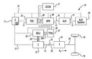
- FIG. 1is a schematic illustration of a high-voltage (HV) propelled vehicle having an HV direct current (DC) bus that is shared by multiple HV power electronic converter devices;
- HVhigh-voltage
- DCdirect current
- FIG. 2is a schematic electric circuit diagram for a shared HV DC bus connecting a Traction Power Inverter Module (TPIM) and an Air Conditioning Compressor Module (ACCM) aboard the vehicle shown in FIG. 1 ;
- TPIMTraction Power Inverter Module
- ACCMAir Conditioning Compressor Module
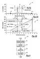
- FIG. 3Ais an electrical resonance bode-plot diagram for the circuit shown in FIG. 2 ;
- FIG. 3Bis a plot of a modified TPIM PWM switching profile in accordance with the invention.
- FIG. 4is a flow chart describing the method or algorithm of the present invention.
- FIG. 1shows a high-voltage (HV) propelled vehicle 10 .
- the vehicle 10which may be configured as a hybrid electric vehicle (HEV) in one embodiment as shown, includes a controller (C) 11 having an algorithm 100 adapted for avoiding electrical resonance on a shared HV direct current (DC) bus 29 as explained below.
- HVhigh-voltage
- DCdirect current
- the vehicle 10may include an internal combustion engine (E) 12 having an input member (not shown) and an output member 15 when configured as an HEV as shown.
- the vehicle 10includes a transmission (T) 14 having an input member 22 and an output member 24 .
- Output member 15 of the engine 12may be selectively connected to the input member 22 of the transmission 14 via a torque transfer mechanism 18 .
- the transmission 14may be configured as an electrically variable transmission (EVT) or any other suitable transmission capable of transmitting propulsive torque to a set of road wheels 16 via output member 24 of the transmission.
- Output member 24rotates at an output speed (N O ) in response to an output speed request, which is ultimately determined by the controller 11 based on a set of driver inputs or commands.
- the vehicle 10may include an HV electric motor/generator unit (MGU) 26 , such as a multi-phase electric machine of approximately 60 volts to approximately 300 volts or more depending on the vehicle design.
- the MGU 26is electrically connected to an HV energy storage system (ESS) 25 , e.g., a rechargeable battery, via a traction power inverter module (TPIM) 27 , an HV alternating current (AC) bus 29 A for conducting a multi-phase current to the MGU, and the HV DC bus 29 .
- ESSHV energy storage system
- TPIMtraction power inverter module
- ACHV alternating current
- the MGU 26may be used to selectively rotate a belt 23 of the engine 12 , or another suitable portion thereof, thereby cranking the engine during a restart event.
- the ESS 25may be selectively recharged using the MGU 26 when the MGU is operating in its capacity as a generator, for example by capturing energy during a regenerative braking event.
- the HV DC bus 29is shared by multiple power electronic converters, such as but not necessarily limited to the TPIM 27 , an air conditioning compressor inverter module (ACCM) 17 , and an auxiliary power module (APM) 28 such as a DC-to-DC converter.
- the APM 28may be electrically connected to an auxiliary battery (AUX) 41 , e.g., a 12-volt DC battery, via a low-voltage (LV) bus 19 , and adapted for energizing one or more auxiliary systems 45 aboard the vehicle 10 .
- AUXauxiliary battery
- LVlow-voltage
- the controller 11may be configured as a single or a distributed control device that is electrically connected to or otherwise in hard-wired or wireless communication with each of the engine 12 , the ESS 25 , the MGU 26 , the TPIM 27 , the APM 28 , and the auxiliary battery 41 via control channels 51 , as illustrated by dashed lines.
- Control channels 51may include any required transfer conductors, e.g., a hard-wired or wireless control link(s) or path(s) suitable for transmitting and receiving the necessary electrical control signals for proper power flow control and coordination aboard the vehicle 10 .
- the controller 11may include such control modules and capabilities as might be necessary to execute all required power flow control functionality aboard the vehicle 10 in the desired manner.
- the controller 11may be configured as a digital computer device or devices generally comprising a microprocessor or central processing unit (CPU), read only memory (ROM), random access memory (RAM), electrically-erasable programmable read only memory (EEPROM), a high-speed clock, analog-to-digital (A/D) and digital-to-analog (D/A) circuitry, and input/output circuitry and devices (I/O), as well as appropriate signal conditioning and buffer circuitry.
- the controller 11includes or has access to the algorithm 100 mentioned above and described below with reference to FIG. 4 , and is adapted to execute the algorithm 100 to avoid electrical resonance in the shared HV DC bus 29 .
- the TPIM 27may be configured as a pulse-width modulated (PWM) inverter device, where the PWM switching frequency thereof follows a profile that varies between calibrated low and high values, e.g., approximately 2 kHz to approximately 12 kHz according to one embodiment. This frequency variation occurs as a function of motor operating speed and torque, i.e., the rotational output speed and torque of MGU 26 , to achieve certain performance objectives.
- PWMpulse-width modulated
- Such objectivesmay include but are not necessarily limited to a quiet vehicle cranking, improved or optimized inverter efficiency, and lower thermal stresses.
- the ACCM 17shares the HV DC bus 29 with the TPIM 27 , and carries significant power flow.
- the ACCM 17may have a PWM switching frequency of approximately 10 kHz according to one embodiment, and may contain thermal stresses on its internal power switches.
- filter componentssuch as inductors and capacitors may be selected such that there is an electrical resonance frequency, as noted in the background section hereinabove, that falls within the limits of the PWM switching range of the TPIM 27 .
- One way to avoid electrical resonanceis to design or select the filter components of the ACCM 17 so as to reduce the resonance frequency below the low end of the predetermined TPIM switching range, e.g., below approximately 2 kHz in the embodiment noted previously hereinabove, or above the high end of the switching range, e.g., above 12 kHz, in the example set forth above.
- the filter componentsmay be too large to implement, both in packaging size as well as cost.
- the filter componentsmay be too small to meet ripple requirements, and to ensure control stability and current regulation for the ACCM 17 .
- the controller 11is thus adapted to provide a software-based solution in the form of the algorithm 100 as set forth herein, which when executed by the controller provides an optimal PWM switching frequency profile, i.e., a profile that avoids the resonance frequency range between the TPIM 27 and the ACCM 17 on the shared HV DC bus 29 .
- a diagram of an HV circuit 30shows the HV DC bus 29 , the ACCM 17 , and the TPIM 27 , with the ACCM and TPIM being a representative pair of power electronic converter devices as described above.
- integrated circuit componentsmay include a capacitor 34 A and an equivalent series inductance device 32 A, e.g., a bus bar, inductors, common-mode choke device, etc.
- the ACCM 17which shares the DC bus 29 with the TPIM 27 , includes similar integrated circuit components in capacitor 34 B and equivalent series inductance device 32 B.
- HV cables 36are used to connect the ACCM 17 and TPM, thus completing the HV circuit 30 .
- the capacitance and inductance values used in this particular equationwill vary due to part-to-part tolerances, circuit temperature fluctuations, and vehicle-to-vehicle layout differences, and the resultant resonant frequency (F R ) is in the form of a frequency range rather than a discrete frequency due largely to the part-to-part tolerances and temperature variation of the various components in the HV circuit 30 .
- FIGS. 3A and 3Ba frequency response plot 40 is shown ( FIG. 3A ) relative to a switching frequency plot 50 ( FIG. 3B ).
- FIG. 3Athe cases of a minimum resonance frequency 53 , a typical resonance frequency 54 , and a maximum resonance frequency 55 are plotted for the ACCM 17 of FIG. 1 , along with a resonance zone 57 that is created with respect to these values.
- a maximum current or ACCM cap current 44divides the resonance zone 57 as shown.
- a solution for avoiding electrical resonance in the HV circuit 30 of FIG. 2should consider all of these combinations, covering the outer envelope, i.e., approximately 2 kHz at point 70 to approximately 12 kHz at point 72 in the embodiment shown in FIG. 3A .
- FIG. 3Ashows that the resonance current (I res ) varies with respect to the resonance frequency.
- a maximum current 44 of approximately 120 ampsmay be determined via lines 47 and 48 corresponding to frequencies F 1 and F 2 , respectively of FIG. 3B . From this, it is observed that a worst case resonance current (I res ) may be determined to flow through all of the filter components shown in FIG. 2 as described above. Of these, the capacitor 34 B within the ACCM 17 may be the weakest component in terms of its ability to withstand a resonance current oscillation.
- the peak current or ACCM cap current 44 of approximately 120 ampsshould be avoided.
- the proposed modification to the TPIM switching frequency profile to avoid this current 44is shown via the switching frequency plot 50 of FIG. 3B .
- the resonance current (I res )is less than 120 A, as seen by following line 48 between FIGS. 3A and 3B .
- no PWM switching profile modificationis needed.
- a resonance dead zone 80may be defined by the corner points 62 , 63 , 64 , 65 that should be avoided in terms of the corresponding switching frequency (F 1 and F 2 ), motor torque (T 1 and T 2 ), and motor speed ( ⁇ 1 , ⁇ 2 , ⁇ 3 , and ⁇ 4 ). These frequency, torque, and speed corner points may be calibrated based on the desired vehicle control strategy.
- the dead zone 80could be different for different vehicles. Also, the strategy may differ for different motors within a vehicle based on the performance tradeoffs.
- the strategy of choosing a TPIM switching frequencymay be determined by considering the following performance-related tradeoffs: (a) TPIM efficiency and maximum junction temperature changes, (b) control dynamics, current regulator bandwidth, and dead time effects; (c) quality of AC phase current and torque ripple changes; (d) DC current/voltage ripple and filter capacitor root mean square (RMS) current; (e) hysteresis on switching frequency implementation, and (f) vehicle performance.
- the controller 11may be configured to change a pre-calculated TPIM PWM switching frequency (F sw ) based on its relation to the parameters of dead zone 80 . Such a determination may be made during calibration of the vehicle 10 of FIG. 1 based on the performance-related tradeoffs outlined above. At least three options, i.e., Options I, II, and III, may be implemented as noted below with respect to step 106 .
- the algorithm 100first determines the impedance characteristics of the shared HV DC bus 29 to ultimately determine a set of resonance points. For example, the equivalent impedance of circuit 30 of FIG. 2 may be calculated. Step 101 may be executed for a range of parameter values, i.e., the impedance and capacitance values may vary within the circuit of FIG. 2 , resulting in different frequency response plots as shown in FIG. 3A . Once the impedance characteristics of the shared HV DC bus 29 are determined, the algorithm 100 proceeds to step 102 .
- the algorithm 100defines the resonance zone 57 of FIG. 3A for the HV circuit 30 of FIG. 2 , with the ultimate goal of avoiding this resonance zone during operation of the vehicle 10 . Once the resonance zone 57 is determined, the algorithm 100 proceeds to step 104 .
- the points 62 , 63 , 64 , and 65 defining and recording the dead zone 80are determined using the resonance zone 57 shown in FIG. 3A . That is, the dead zone 80 is defined in terms of switching frequency (F 1 and F 2 ), which defines the lower and upper frequency boundaries of the dead zone via lines 47 and 48 , respectively; motor torque (T 1 and T 2 ) of the MGU 26 shown in FIG. 1 , and motor speed ( ⁇ 1 , ⁇ 2 , ⁇ 3 , and ⁇ 4 ).
- Step 102chooses the lower and upper frequency boundaries, i.e., F 1 and F 2 , for the switching frequency for TPIM 27 of FIG. 1 , such that the TPIM does not excite the resonance on the shared HV DC bus 29 .
- the algorithm 100proceeds to step 106 .
- the algorithm 100executes one of a predetermined plurality of control actions to prevent the TPIM 27 from operating within the range (F 1 , F 2 ) and to avoid the resonance in the shared HV DC bus 29 .
- a time-based hysteresismay also be implemented together with Options I-III.
- algorithm 100may automatically clamp to the upper or lower limit of the dead zone, i.e., either F1 or F2. If the TPIM switching frequency (F sw is less than the lower limit (F 1 of FIG. 3B ) for greater than a calibrated duration, the pre-calculated TPIM switching frequency (F sw ) may continue to be used, with the algorithm 100 otherwise clamping to the upper or lower edge or limit, or lines 47 or 48 of FIG. 3A , respectively.
Landscapes
- Engineering & Computer Science (AREA)
- Power Engineering (AREA)
- Transportation (AREA)
- Mechanical Engineering (AREA)
- Chemical & Material Sciences (AREA)
- Combustion & Propulsion (AREA)
- Physics & Mathematics (AREA)
- Electromagnetism (AREA)
- Electric Propulsion And Braking For Vehicles (AREA)
- Inverter Devices (AREA)
Abstract
Description
Claims (11)
Priority Applications (3)
| Application Number | Priority Date | Filing Date | Title |
|---|---|---|---|
| US12/614,464US8288886B2 (en) | 2009-11-09 | 2009-11-09 | Method and apparatus for avoiding electrical resonance in a vehicle having a shared high-voltage bus |
| DE102010050383.5ADE102010050383B4 (en) | 2009-11-09 | 2010-11-03 | A method and apparatus for avoiding electrical resonances in a vehicle having a shared high voltage bus |
| CN2010105456169ACN102055309B (en) | 2009-11-09 | 2010-11-09 | Method and apparatus for avoiding electrical resonance in a vehicle having a shared high-voltage bus |
Applications Claiming Priority (1)
| Application Number | Priority Date | Filing Date | Title |
|---|---|---|---|
| US12/614,464US8288886B2 (en) | 2009-11-09 | 2009-11-09 | Method and apparatus for avoiding electrical resonance in a vehicle having a shared high-voltage bus |
Publications (2)
| Publication Number | Publication Date |
|---|---|
| US20110109155A1 US20110109155A1 (en) | 2011-05-12 |
| US8288886B2true US8288886B2 (en) | 2012-10-16 |
Family
ID=43959353
Family Applications (1)
| Application Number | Title | Priority Date | Filing Date |
|---|---|---|---|
| US12/614,464Active2030-09-30US8288886B2 (en) | 2009-11-09 | 2009-11-09 | Method and apparatus for avoiding electrical resonance in a vehicle having a shared high-voltage bus |
Country Status (3)
| Country | Link |
|---|---|
| US (1) | US8288886B2 (en) |
| CN (1) | CN102055309B (en) |
| DE (1) | DE102010050383B4 (en) |
Cited By (15)
| Publication number | Priority date | Publication date | Assignee | Title |
|---|---|---|---|---|
| US9054611B2 (en) | 2013-06-29 | 2015-06-09 | Rockwell Automation Technologies, Inc. | Method and apparatus for stability control of open loop motor drive operation |
| US9124209B2 (en) | 2013-01-16 | 2015-09-01 | Rockwell Automation Technologies, Inc. | Method and apparatus for controlling power converter with inverter output filter |
| US9287812B2 (en) | 2013-06-29 | 2016-03-15 | Rockwell Automation Technologies, Inc. | Method and apparatus for stability control of open loop motor drive operation |
| US9294019B2 (en) | 2013-01-16 | 2016-03-22 | Rockwell Automation Technologies, Inc. | Method and apparatus for controlling power converter with inverter output filter |
| US9312779B2 (en) | 2013-04-23 | 2016-04-12 | Rockwell Automation Technologies, Inc. | Position sensorless open loop control for motor drives with output filter and transformer |
| US9374028B2 (en) | 2014-08-22 | 2016-06-21 | Rockwell Automation Technologies, Inc. | Transition scheme for position sensorless control of AC motor drives |
| US9446668B2 (en) | 2012-08-27 | 2016-09-20 | Siemens Aktiengesellschaft | Drive method with shifting of the switching frequency and drive device |
| US9490738B2 (en) | 2013-01-16 | 2016-11-08 | Rockwell Automation Technologies, Inc. | Sensorless motor drive vector control |
| US9716460B2 (en) | 2015-01-28 | 2017-07-25 | Rockwell Automation Technologies, Inc. | Method and apparatus for speed reversal control of motor drive |
| US9774284B2 (en) | 2015-02-19 | 2017-09-26 | Rockwell Automation Technologies, Inc. | Rotor position estimation apparatus and methods |
| US9800190B2 (en) | 2016-02-03 | 2017-10-24 | Rockwell Automation Technologies, Inc. | Control of motor drives with output sinewave filter capacitor current compensation using sinewave filter transfer function |
| US9802604B2 (en) | 2014-05-23 | 2017-10-31 | Ford Global Technologies, Llc | Methods and systems for improving hybrid vehicle efficiency |
| US9985565B2 (en) | 2016-04-18 | 2018-05-29 | Rockwell Automation Technologies, Inc. | Sensorless motor drive vector control with feedback compensation for filter capacitor current |
| US10020766B2 (en) | 2016-11-15 | 2018-07-10 | Rockwell Automation Technologies, Inc. | Current control of motor drives with output sinewave filter |
| US10158314B2 (en) | 2013-01-16 | 2018-12-18 | Rockwell Automation Technologies, Inc. | Feedforward control of motor drives with output sinewave filter |
Families Citing this family (17)
| Publication number | Priority date | Publication date | Assignee | Title |
|---|---|---|---|---|
| DE102011017008A1 (en)* | 2011-04-14 | 2012-10-18 | Daimler Ag | On-board electrical system for e.g. passenger car, has standard sub-network for providing electricity to standard load, and supplementary service section network for supplying electricity to achievement consumer |
| US8912754B2 (en) | 2011-11-22 | 2014-12-16 | GM Global Technology Operations LLC | System and method for controlling exchange of current |
| JP5953144B2 (en) | 2012-06-29 | 2016-07-20 | 山洋電気株式会社 | Motor control device |
| DE102012214544A1 (en)* | 2012-08-16 | 2014-02-20 | Robert Bosch Gmbh | Onboard network for motor car has control device that has processing unit to send communication signals electrically isolated from power supply voltage of loads to actuate loads via communication channels |
| JP5673629B2 (en)* | 2012-08-29 | 2015-02-18 | 株式会社豊田自動織機 | LC filter protection device |
| CN105164913B (en) | 2013-03-29 | 2017-07-14 | 爱信艾达株式会社 | Electric rotating machine drive device |
| US9312800B2 (en)* | 2014-08-25 | 2016-04-12 | Fca Us Llc | Control techniques for an interior permanent magnet synchronous motor of an electrified vehicle |
| DE102014222913A1 (en)* | 2014-11-11 | 2016-05-12 | Bayerische Motoren Werke Aktiengesellschaft | Improved control device for a starter motor |
| DE102014018664A1 (en)* | 2014-12-13 | 2016-06-16 | Baumüller Nürnberg GmbH | Method for operating an inverter and converters |
| US9985452B2 (en)* | 2016-03-03 | 2018-05-29 | GM Global Technology Operations LLC | Apparatus for discharging a high-voltage bus |
| JP7013846B2 (en)* | 2017-12-21 | 2022-02-01 | トヨタ自動車株式会社 | Electric car |
| CN111256276A (en)* | 2018-11-30 | 2020-06-09 | 广东美的制冷设备有限公司 | Operation control method and system, compressor and air conditioner |
| EP3906185A4 (en)* | 2019-01-02 | 2022-10-05 | TVS Motor Company Limited | SEPARATE HARNESS ARRANGEMENT FOR HIGH AND LOW VOLTAGE |
| CN109861571B (en)* | 2019-02-22 | 2020-11-10 | 湖南大学 | Drive method and system for improving reliability of SiC inverter |
| JP7644640B2 (en)* | 2021-03-25 | 2025-03-12 | 株式会社Subaru | Vehicle control device |
| JP7594476B2 (en)* | 2021-03-25 | 2024-12-04 | 株式会社Subaru | Vehicle control device |
| DE102023134986A1 (en)* | 2023-12-13 | 2025-06-18 | Sma Solar Technology Ag | POWER CONVERTER WITH MULTIPLE CONVERTER MODULES |
Citations (9)
| Publication number | Priority date | Publication date | Assignee | Title |
|---|---|---|---|---|
| US5099186A (en)* | 1990-12-31 | 1992-03-24 | General Motors Inc. | Integrated motor drive and recharge system |
| US20030150352A1 (en)* | 2001-03-27 | 2003-08-14 | General Electric Company | Hybrid energy off highway vehicle electric power storage system and method |
| US20060237247A1 (en)* | 1998-09-14 | 2006-10-26 | Paice Llc | Hybrid vehicles |
| US20070227788A1 (en)* | 2004-05-27 | 2007-10-04 | Toyota Jidosha Kabushiki Kaisha 1, Toyota-Cho | Electric Vehicle Control Apparatus |
| US20080298785A1 (en)* | 2007-05-31 | 2008-12-04 | Patel Nitinkumar R | Method and system for operating a motor to reduce noise in an electric vehicle |
| US20090066277A1 (en)* | 2006-06-22 | 2009-03-12 | Toyota Jidosha Kabushiki Kaisha | Voltage Conversion Apparatus and Vehicle Including the Same |
| JP2009060723A (en)* | 2007-08-31 | 2009-03-19 | Fuji Electric Systems Co Ltd | Control device for power conversion device and stationary auxiliary power supply device for vehicle |
| US20090134828A1 (en)* | 2007-11-27 | 2009-05-28 | Gm Global Technology Operations, Inc. | Method and system for operating an electric motor coupled to multiple power supplies |
| US7748482B2 (en)* | 2006-10-25 | 2010-07-06 | Gm Global Technology Operations, Inc. | Accessory drive system for a hybrid vehicle |
Family Cites Families (6)
| Publication number | Priority date | Publication date | Assignee | Title |
|---|---|---|---|---|
| JPH03145995A (en)* | 1989-11-01 | 1991-06-21 | Fuji Electric Co Ltd | Control of inverter |
| EP1522450A3 (en)* | 1998-09-14 | 2005-06-22 | Paice LLC | Engine start and shutdown control in hybrid vehicles |
| US7185591B2 (en)* | 2001-03-27 | 2007-03-06 | General Electric Company | Hybrid energy off highway vehicle propulsion circuit |
| JP2003219691A (en)* | 2002-01-17 | 2003-07-31 | Meidensha Corp | Drive system for permanent-magnet synchronous motor and test method therefor |
| DE102005050842B4 (en)* | 2005-10-24 | 2011-06-09 | Siemens Ag | Method for operating an inverter and circuit arrangement |
| US8289033B2 (en)* | 2009-01-23 | 2012-10-16 | GM Global Technology Operations LLC | Systems and methods for detecting resonance on a direct current voltage bus |
- 2009
- 2009-11-09USUS12/614,464patent/US8288886B2/enactiveActive
- 2010
- 2010-11-03DEDE102010050383.5Apatent/DE102010050383B4/enactiveActive
- 2010-11-09CNCN2010105456169Apatent/CN102055309B/enactiveActive
Patent Citations (9)
| Publication number | Priority date | Publication date | Assignee | Title |
|---|---|---|---|---|
| US5099186A (en)* | 1990-12-31 | 1992-03-24 | General Motors Inc. | Integrated motor drive and recharge system |
| US20060237247A1 (en)* | 1998-09-14 | 2006-10-26 | Paice Llc | Hybrid vehicles |
| US20030150352A1 (en)* | 2001-03-27 | 2003-08-14 | General Electric Company | Hybrid energy off highway vehicle electric power storage system and method |
| US20070227788A1 (en)* | 2004-05-27 | 2007-10-04 | Toyota Jidosha Kabushiki Kaisha 1, Toyota-Cho | Electric Vehicle Control Apparatus |
| US20090066277A1 (en)* | 2006-06-22 | 2009-03-12 | Toyota Jidosha Kabushiki Kaisha | Voltage Conversion Apparatus and Vehicle Including the Same |
| US7748482B2 (en)* | 2006-10-25 | 2010-07-06 | Gm Global Technology Operations, Inc. | Accessory drive system for a hybrid vehicle |
| US20080298785A1 (en)* | 2007-05-31 | 2008-12-04 | Patel Nitinkumar R | Method and system for operating a motor to reduce noise in an electric vehicle |
| JP2009060723A (en)* | 2007-08-31 | 2009-03-19 | Fuji Electric Systems Co Ltd | Control device for power conversion device and stationary auxiliary power supply device for vehicle |
| US20090134828A1 (en)* | 2007-11-27 | 2009-05-28 | Gm Global Technology Operations, Inc. | Method and system for operating an electric motor coupled to multiple power supplies |
Non-Patent Citations (1)
| Title |
|---|
| JP Pub 2007-202385 to Kawakami et al., english abstract, Aug. 9, 2007, B6OL 9-18.* |
Cited By (15)
| Publication number | Priority date | Publication date | Assignee | Title |
|---|---|---|---|---|
| US9446668B2 (en) | 2012-08-27 | 2016-09-20 | Siemens Aktiengesellschaft | Drive method with shifting of the switching frequency and drive device |
| US9294019B2 (en) | 2013-01-16 | 2016-03-22 | Rockwell Automation Technologies, Inc. | Method and apparatus for controlling power converter with inverter output filter |
| US9124209B2 (en) | 2013-01-16 | 2015-09-01 | Rockwell Automation Technologies, Inc. | Method and apparatus for controlling power converter with inverter output filter |
| US9490738B2 (en) | 2013-01-16 | 2016-11-08 | Rockwell Automation Technologies, Inc. | Sensorless motor drive vector control |
| US10158314B2 (en) | 2013-01-16 | 2018-12-18 | Rockwell Automation Technologies, Inc. | Feedforward control of motor drives with output sinewave filter |
| US9312779B2 (en) | 2013-04-23 | 2016-04-12 | Rockwell Automation Technologies, Inc. | Position sensorless open loop control for motor drives with output filter and transformer |
| US9054611B2 (en) | 2013-06-29 | 2015-06-09 | Rockwell Automation Technologies, Inc. | Method and apparatus for stability control of open loop motor drive operation |
| US9287812B2 (en) | 2013-06-29 | 2016-03-15 | Rockwell Automation Technologies, Inc. | Method and apparatus for stability control of open loop motor drive operation |
| US9802604B2 (en) | 2014-05-23 | 2017-10-31 | Ford Global Technologies, Llc | Methods and systems for improving hybrid vehicle efficiency |
| US9374028B2 (en) | 2014-08-22 | 2016-06-21 | Rockwell Automation Technologies, Inc. | Transition scheme for position sensorless control of AC motor drives |
| US9716460B2 (en) | 2015-01-28 | 2017-07-25 | Rockwell Automation Technologies, Inc. | Method and apparatus for speed reversal control of motor drive |
| US9774284B2 (en) | 2015-02-19 | 2017-09-26 | Rockwell Automation Technologies, Inc. | Rotor position estimation apparatus and methods |
| US9800190B2 (en) | 2016-02-03 | 2017-10-24 | Rockwell Automation Technologies, Inc. | Control of motor drives with output sinewave filter capacitor current compensation using sinewave filter transfer function |
| US9985565B2 (en) | 2016-04-18 | 2018-05-29 | Rockwell Automation Technologies, Inc. | Sensorless motor drive vector control with feedback compensation for filter capacitor current |
| US10020766B2 (en) | 2016-11-15 | 2018-07-10 | Rockwell Automation Technologies, Inc. | Current control of motor drives with output sinewave filter |
Also Published As
| Publication number | Publication date |
|---|---|
| DE102010050383A1 (en) | 2011-06-22 |
| CN102055309A (en) | 2011-05-11 |
| US20110109155A1 (en) | 2011-05-12 |
| CN102055309B (en) | 2013-09-18 |
| DE102010050383B4 (en) | 2017-08-03 |
Similar Documents
| Publication | Publication Date | Title |
|---|---|---|
| US8288886B2 (en) | Method and apparatus for avoiding electrical resonance in a vehicle having a shared high-voltage bus | |
| US8058830B2 (en) | Charging energy sources with a rectifier using double-ended inverter system | |
| US7956563B2 (en) | System for using a multi-phase motor with a double-ended inverter system | |
| US7956569B2 (en) | Double ended inverter system with an impedance source inverter subsystem | |
| CN102549876B (en) | Power supply system for vehicle | |
| JP4780402B2 (en) | Vehicle power supply | |
| US10118495B2 (en) | Vehicle power distribution having relay with integrated voltage converter | |
| CN102202931B (en) | Electric power source system for electrically driven vehicle and its control method | |
| US7952224B2 (en) | Power supply system, vehicle including the power supply system, control method for power supply system, and computer-readable recording medium having program recorded thereon for computer to execute the control method | |
| US8026691B2 (en) | Double ended inverter system with a cross-linked ultracapacitor network | |
| US7576500B2 (en) | Method and system for operating a motor to reduce noise in an electric vehicle | |
| KR101017089B1 (en) | Motor drive device and control method | |
| US7990098B2 (en) | Series-coupled two-motor drive using double-ended inverter system | |
| US8054032B2 (en) | Discontinuous pulse width modulation for double-ended inverter system | |
| US8002056B2 (en) | Double-ended inverter system with isolated neutral topology | |
| US8102142B2 (en) | Double ended inverter system for a vehicle having two energy sources that exhibit different operating characteristics | |
| US9018894B2 (en) | Vehicular power supply system | |
| US20090108780A1 (en) | Method and system for controlling a power inverter in electric drives | |
| US20030117113A1 (en) | Hybrid vehicle and control method therefor | |
| JP7178892B2 (en) | vehicle battery charging controller | |
| KR20080070869A (en) | Charging device, electric vehicle and charging system | |
| US10967743B2 (en) | Hybrid drive system | |
| JPH11514838A (en) | Voltage supply device for vehicles | |
| JP2019054673A (en) | Power supply apparatus | |
| US11673542B2 (en) | Controller of vehicle |
Legal Events
| Date | Code | Title | Description |
|---|---|---|---|
| AS | Assignment | Owner name:GM GLOBAL TECHNOLOGY OPERATIONS, INC., MICHIGAN Free format text:ASSIGNMENT OF ASSIGNORS INTEREST;ASSIGNORS:ANWAR, MOHAMMAD N.;SCHULZ, STEVEN E.;GREEN, STEPHAN N.;AND OTHERS;SIGNING DATES FROM 20091020 TO 20091028;REEL/FRAME:023487/0221 | |
| AS | Assignment | Owner name:UNITED STATES DEPARTMENT OF THE TREASURY, DISTRICT Free format text:SECURITY AGREEMENT;ASSIGNOR:GM GLOBAL TECHNOLOGY OPERATIONS, INC.;REEL/FRAME:023989/0155 Effective date:20090710 Owner name:UAW RETIREE MEDICAL BENEFITS TRUST, MICHIGAN Free format text:SECURITY AGREEMENT;ASSIGNOR:GM GLOBAL TECHNOLOGY OPERATIONS, INC.;REEL/FRAME:023990/0001 Effective date:20090710 | |
| AS | Assignment | Owner name:GM GLOBAL TECHNOLOGY OPERATIONS, INC., MICHIGAN Free format text:RELEASE BY SECURED PARTY;ASSIGNOR:UNITED STATES DEPARTMENT OF THE TREASURY;REEL/FRAME:025246/0234 Effective date:20100420 | |
| AS | Assignment | Owner name:GM GLOBAL TECHNOLOGY OPERATIONS, INC., MICHIGAN Free format text:RELEASE BY SECURED PARTY;ASSIGNOR:UAW RETIREE MEDICAL BENEFITS TRUST;REEL/FRAME:025315/0136 Effective date:20101026 | |
| AS | Assignment | Owner name:WILMINGTON TRUST COMPANY, DELAWARE Free format text:SECURITY AGREEMENT;ASSIGNOR:GM GLOBAL TECHNOLOGY OPERATIONS, INC.;REEL/FRAME:025324/0555 Effective date:20101027 | |
| AS | Assignment | Owner name:GM GLOBAL TECHNOLOGY OPERATIONS LLC, MICHIGAN Free format text:CHANGE OF NAME;ASSIGNOR:GM GLOBAL TECHNOLOGY OPERATIONS, INC.;REEL/FRAME:025781/0299 Effective date:20101202 | |
| FEPP | Fee payment procedure | Free format text:PAYOR NUMBER ASSIGNED (ORIGINAL EVENT CODE: ASPN); ENTITY STATUS OF PATENT OWNER: LARGE ENTITY | |
| STCF | Information on status: patent grant | Free format text:PATENTED CASE | |
| AS | Assignment | Owner name:GM GLOBAL TECHNOLOGY OPERATIONS LLC, MICHIGAN Free format text:RELEASE BY SECURED PARTY;ASSIGNOR:WILMINGTON TRUST COMPANY;REEL/FRAME:034287/0001 Effective date:20141017 | |
| FPAY | Fee payment | Year of fee payment:4 | |
| MAFP | Maintenance fee payment | Free format text:PAYMENT OF MAINTENANCE FEE, 8TH YEAR, LARGE ENTITY (ORIGINAL EVENT CODE: M1552); ENTITY STATUS OF PATENT OWNER: LARGE ENTITY Year of fee payment:8 | |
| MAFP | Maintenance fee payment | Free format text:PAYMENT OF MAINTENANCE FEE, 12TH YEAR, LARGE ENTITY (ORIGINAL EVENT CODE: M1553); ENTITY STATUS OF PATENT OWNER: LARGE ENTITY Year of fee payment:12 |