US8288600B2 - Methods for co-processing of biomass and petroleum feed - Google Patents
Methods for co-processing of biomass and petroleum feedDownload PDFInfo
- Publication number
- US8288600B2 US8288600B2US12/917,988US91798810AUS8288600B2US 8288600 B2US8288600 B2US 8288600B2US 91798810 AUS91798810 AUS 91798810AUS 8288600 B2US8288600 B2US 8288600B2
- Authority
- US
- United States
- Prior art keywords
- biomass
- catalyst
- biomass material
- riser
- suspension
- Prior art date
- Legal status (The legal status is an assumption and is not a legal conclusion. Google has not performed a legal analysis and makes no representation as to the accuracy of the status listed.)
- Expired - Fee Related
Links
- 239000002028BiomassSubstances0.000titleclaimsabstractdescription447
- 238000000034methodMethods0.000titleclaimsabstractdescription114
- 238000012545processingMethods0.000titledescription34
- 239000003208petroleumSubstances0.000titledescription5
- 239000000463materialSubstances0.000claimsabstractdescription370
- 239000002245particleSubstances0.000claimsabstractdescription108
- 239000007788liquidSubstances0.000claimsabstractdescription95
- 230000008569processEffects0.000claimsabstractdescription80
- 150000002430hydrocarbonsChemical class0.000claimsabstractdescription77
- 229930195733hydrocarbonNatural products0.000claimsabstractdescription74
- 239000004215Carbon black (E152)Substances0.000claimsabstractdescription60
- 239000000725suspensionSubstances0.000claimsabstractdescription44
- 239000000446fuelSubstances0.000claimsabstractdescription38
- 239000012530fluidSubstances0.000claimsabstractdescription9
- 238000004231fluid catalytic crackingMethods0.000claimsabstractdescription8
- 238000004517catalytic hydrocrackingMethods0.000claimsabstractdescription5
- 230000003111delayed effectEffects0.000claimsabstractdescription5
- 238000000197pyrolysisMethods0.000claimsabstractdescription5
- 239000003054catalystSubstances0.000claimsdescription190
- 239000003921oilSubstances0.000claimsdescription50
- 239000007787solidSubstances0.000claimsdescription50
- 239000002904solventSubstances0.000claimsdescription48
- 238000006243chemical reactionMethods0.000claimsdescription40
- 239000000203mixtureSubstances0.000claimsdescription40
- 229910052500inorganic mineralInorganic materials0.000claimsdescription33
- 239000011707mineralSubstances0.000claimsdescription33
- 230000002328demineralizing effectEffects0.000claimsdescription21
- QTBSBXVTEAMEQO-UHFFFAOYSA-NAcetic acidChemical compoundCC(O)=OQTBSBXVTEAMEQO-UHFFFAOYSA-N0.000claimsdescription18
- 238000005115demineralizationMethods0.000claimsdescription16
- 238000010438heat treatmentMethods0.000claimsdescription15
- 239000003125aqueous solventSubstances0.000claimsdescription12
- 239000002253acidSubstances0.000claimsdescription9
- 239000012876carrier materialSubstances0.000claimsdescription8
- 238000002156mixingMethods0.000claimsdescription8
- 239000002002slurrySubstances0.000claimsdescription8
- 230000002378acidificating effectEffects0.000claimsdescription7
- HYBBIBNJHNGZAN-UHFFFAOYSA-NfurfuralChemical compoundO=CC1=CC=CO1HYBBIBNJHNGZAN-UHFFFAOYSA-N0.000claimsdescription6
- 239000010779crude oilSubstances0.000claimsdescription4
- 150000007524organic acidsChemical class0.000claimsdescription4
- 125000003118aryl groupChemical group0.000claimsdescription3
- 150000001735carboxylic acidsChemical class0.000claimsdescription3
- 238000002791soakingMethods0.000claimsdescription3
- KYYSIVCCYWZZLR-UHFFFAOYSA-Ncobalt(2+);dioxido(dioxo)molybdenumChemical compound[Co+2].[O-][Mo]([O-])(=O)=OKYYSIVCCYWZZLR-UHFFFAOYSA-N0.000claimsdescription2
- NLPVCCRZRNXTLT-UHFFFAOYSA-Ndioxido(dioxo)molybdenum;nickel(2+)Chemical compound[Ni+2].[O-][Mo]([O-])(=O)=ONLPVCCRZRNXTLT-UHFFFAOYSA-N0.000claimsdescription2
- PBYZMCDFOULPGH-UHFFFAOYSA-NtungstateChemical compound[O-][W]([O-])(=O)=OPBYZMCDFOULPGH-UHFFFAOYSA-N0.000claimsdescription2
- 239000007789gasSubstances0.000description82
- 239000000047productSubstances0.000description51
- 238000004523catalytic crackingMethods0.000description35
- 235000019198oilsNutrition0.000description34
- 230000003197catalytic effectEffects0.000description31
- XLYOFNOQVPJJNP-UHFFFAOYSA-NwaterSubstancesOXLYOFNOQVPJJNP-UHFFFAOYSA-N0.000description29
- 229910001868waterInorganic materials0.000description29
- 239000000126substanceSubstances0.000description23
- LFQSCWFLJHTTHZ-UHFFFAOYSA-NEthanolChemical compoundCCOLFQSCWFLJHTTHZ-UHFFFAOYSA-N0.000description22
- CURLTUGMZLYLDI-UHFFFAOYSA-NCarbon dioxideChemical compoundO=C=OCURLTUGMZLYLDI-UHFFFAOYSA-N0.000description20
- UGFAIRIUMAVXCW-UHFFFAOYSA-NCarbon monoxideChemical compound[O+]#[C-]UGFAIRIUMAVXCW-UHFFFAOYSA-N0.000description20
- 229910010272inorganic materialInorganic materials0.000description18
- 239000011147inorganic materialSubstances0.000description18
- 229910002092carbon dioxideInorganic materials0.000description17
- 239000003546flue gasSubstances0.000description17
- QVGXLLKOCUKJST-UHFFFAOYSA-Natomic oxygenChemical compound[O]QVGXLLKOCUKJST-UHFFFAOYSA-N0.000description16
- 229910052760oxygenInorganic materials0.000description16
- 239000001301oxygenSubstances0.000description16
- 238000013019agitationMethods0.000description14
- 239000002184metalSubstances0.000description14
- 229910052751metalInorganic materials0.000description14
- 239000011236particulate materialSubstances0.000description12
- 239000003570airSubstances0.000description11
- 230000002209hydrophobic effectEffects0.000description11
- 238000000227grindingMethods0.000description10
- -1unsaturatedSubstances0.000description10
- 150000004679hydroxidesChemical class0.000description9
- 239000008346aqueous phaseSubstances0.000description8
- 230000008901benefitEffects0.000description8
- 238000013461designMethods0.000description8
- 239000003502gasolineSubstances0.000description8
- 150000003839saltsChemical class0.000description8
- 230000015572biosynthetic processEffects0.000description7
- 150000004649carbonic acid derivativesChemical class0.000description7
- 239000001913celluloseSubstances0.000description7
- 229920002678cellulosePolymers0.000description7
- 239000004927claySubstances0.000description7
- 238000004880explosionMethods0.000description7
- 238000005243fluidizationMethods0.000description7
- 239000000543intermediateSubstances0.000description7
- 229920005610ligninPolymers0.000description7
- 229920002488HemicellulosePolymers0.000description6
- VEXZGXHMUGYJMC-UHFFFAOYSA-NHydrochloric acidChemical compoundClVEXZGXHMUGYJMC-UHFFFAOYSA-N0.000description6
- OKKJLVBELUTLKV-UHFFFAOYSA-NMethanolChemical compoundOCOKKJLVBELUTLKV-UHFFFAOYSA-N0.000description6
- PXHVJJICTQNCMI-UHFFFAOYSA-NNickelChemical compound[Ni]PXHVJJICTQNCMI-UHFFFAOYSA-N0.000description6
- 238000009835boilingMethods0.000description6
- 125000004432carbon atomChemical groupC*0.000description6
- 239000002131composite materialSubstances0.000description6
- GDVKFRBCXAPAQJ-UHFFFAOYSA-Adialuminum;hexamagnesium;carbonate;hexadecahydroxideChemical compound[OH-].[OH-].[OH-].[OH-].[OH-].[OH-].[OH-].[OH-].[OH-].[OH-].[OH-].[OH-].[OH-].[OH-].[OH-].[OH-].[Mg+2].[Mg+2].[Mg+2].[Mg+2].[Mg+2].[Mg+2].[Al+3].[Al+3].[O-]C([O-])=OGDVKFRBCXAPAQJ-UHFFFAOYSA-A0.000description6
- 229910001701hydrotalciteInorganic materials0.000description6
- 229960001545hydrotalciteDrugs0.000description6
- 238000004898kneadingMethods0.000description6
- 239000012263liquid productSubstances0.000description6
- VNWKTOKETHGBQD-UHFFFAOYSA-NmethaneChemical compoundCVNWKTOKETHGBQD-UHFFFAOYSA-N0.000description6
- BDAGIHXWWSANSR-UHFFFAOYSA-Nmethanoic acidNatural productsOC=OBDAGIHXWWSANSR-UHFFFAOYSA-N0.000description6
- 238000003801millingMethods0.000description6
- 239000000243solutionSubstances0.000description6
- OKTJSMMVPCPJKN-UHFFFAOYSA-NCarbonChemical compound[C]OKTJSMMVPCPJKN-UHFFFAOYSA-N0.000description5
- UFHFLCQGNIYNRP-UHFFFAOYSA-NHydrogenChemical compound[H][H]UFHFLCQGNIYNRP-UHFFFAOYSA-N0.000description5
- VYPSYNLAJGMNEJ-UHFFFAOYSA-NSilicium dioxideChemical compoundO=[Si]=OVYPSYNLAJGMNEJ-UHFFFAOYSA-N0.000description5
- 230000009471actionEffects0.000description5
- 229910052799carbonInorganic materials0.000description5
- 150000001875compoundsChemical class0.000description5
- 230000005484gravityEffects0.000description5
- 229910052739hydrogenInorganic materials0.000description5
- 239000001257hydrogenSubstances0.000description5
- 125000002887hydroxy groupChemical group[H]O*0.000description5
- 150000002739metalsChemical class0.000description5
- 238000009420retrofittingMethods0.000description5
- 238000000926separation methodMethods0.000description5
- IJGRMHOSHXDMSA-UHFFFAOYSA-NAtomic nitrogenChemical compoundN#NIJGRMHOSHXDMSA-UHFFFAOYSA-N0.000description4
- XEEYBQQBJWHFJM-UHFFFAOYSA-NIronChemical compound[Fe]XEEYBQQBJWHFJM-UHFFFAOYSA-N0.000description4
- QAOWNCQODCNURD-UHFFFAOYSA-NSulfuric acidChemical compoundOS(O)(=O)=OQAOWNCQODCNURD-UHFFFAOYSA-N0.000description4
- 230000005791algae growthEffects0.000description4
- 239000007864aqueous solutionSubstances0.000description4
- 238000005336crackingMethods0.000description4
- 230000007423decreaseEffects0.000description4
- 238000001035dryingMethods0.000description4
- 230000000694effectsEffects0.000description4
- 238000005516engineering processMethods0.000description4
- 239000005431greenhouse gasSubstances0.000description4
- 239000003915liquefied petroleum gasSubstances0.000description4
- 229910003455mixed metal oxideInorganic materials0.000description4
- 229910052759nickelInorganic materials0.000description4
- 150000002894organic compoundsChemical class0.000description4
- 230000008961swellingEffects0.000description4
- 239000002699waste materialSubstances0.000description4
- OSWFIVFLDKOXQC-UHFFFAOYSA-N4-(3-methoxyphenyl)anilineChemical compoundCOC1=CC=CC(C=2C=CC(N)=CC=2)=C1OSWFIVFLDKOXQC-UHFFFAOYSA-N0.000description3
- PEDCQBHIVMGVHV-UHFFFAOYSA-NGlycerineChemical compoundOCC(O)COPEDCQBHIVMGVHV-UHFFFAOYSA-N0.000description3
- KWYUFKZDYYNOTN-UHFFFAOYSA-MPotassium hydroxideChemical compound[OH-].[K+]KWYUFKZDYYNOTN-UHFFFAOYSA-M0.000description3
- HEMHJVSKTPXQMS-UHFFFAOYSA-MSodium hydroxideChemical compound[OH-].[Na+]HEMHJVSKTPXQMS-UHFFFAOYSA-M0.000description3
- 240000008042Zea maysSpecies0.000description3
- 235000005824Zea mays ssp. parviglumisNutrition0.000description3
- 235000002017Zea mays subsp maysNutrition0.000description3
- 229910021536ZeoliteInorganic materials0.000description3
- 229910052784alkaline earth metalInorganic materials0.000description3
- 150000001336alkenesChemical class0.000description3
- PNEYBMLMFCGWSK-UHFFFAOYSA-Naluminium oxideInorganic materials[O-2].[O-2].[O-2].[Al+3].[Al+3]PNEYBMLMFCGWSK-UHFFFAOYSA-N0.000description3
- 239000002956ashSubstances0.000description3
- 239000012075bio-oilSubstances0.000description3
- 239000001569carbon dioxideSubstances0.000description3
- 229910002091carbon monoxideInorganic materials0.000description3
- 125000002091cationic groupChemical group0.000description3
- KRKNYBCHXYNGOX-UHFFFAOYSA-Ncitric acidChemical compoundOC(=O)CC(O)(C(O)=O)CC(O)=OKRKNYBCHXYNGOX-UHFFFAOYSA-N0.000description3
- 239000000571cokeSubstances0.000description3
- 239000012084conversion productSubstances0.000description3
- 235000005822cornNutrition0.000description3
- HNPSIPDUKPIQMN-UHFFFAOYSA-Ndioxosilane;oxo(oxoalumanyloxy)alumaneChemical compoundO=[Si]=O.O=[Al]O[Al]=OHNPSIPDUKPIQMN-UHFFFAOYSA-N0.000description3
- 238000001704evaporationMethods0.000description3
- 230000008020evaporationEffects0.000description3
- 235000019253formic acidNutrition0.000description3
- 230000006870functionEffects0.000description3
- 230000012010growthEffects0.000description3
- XLYOFNOQVPJJNP-UHFFFAOYSA-MhydroxideChemical compound[OH-]XLYOFNOQVPJJNP-UHFFFAOYSA-M0.000description3
- 239000012535impuritySubstances0.000description3
- 238000005488sandblastingMethods0.000description3
- 238000005549size reductionMethods0.000description3
- 229910000314transition metal oxideInorganic materials0.000description3
- 239000002023woodSubstances0.000description3
- 239000010457zeoliteSubstances0.000description3
- 241000609240Ambelania acidaSpecies0.000description2
- QGZKDVFQNNGYKY-UHFFFAOYSA-NAmmoniaChemical compoundNQGZKDVFQNNGYKY-UHFFFAOYSA-N0.000description2
- RTZKZFJDLAIYFH-UHFFFAOYSA-NDiethyl etherChemical compoundCCOCCRTZKZFJDLAIYFH-UHFFFAOYSA-N0.000description2
- 241000196324EmbryophytaSpecies0.000description2
- DGAQECJNVWCQMB-PUAWFVPOSA-MIlexoside XXIXChemical compoundC[C@@H]1CC[C@@]2(CC[C@@]3(C(=CC[C@H]4[C@]3(CC[C@@H]5[C@@]4(CC[C@@H](C5(C)C)OS(=O)(=O)[O-])C)C)[C@@H]2[C@]1(C)O)C)C(=O)O[C@H]6[C@@H]([C@H]([C@@H]([C@H](O6)CO)O)O)O.[Na+]DGAQECJNVWCQMB-PUAWFVPOSA-M0.000description2
- LRHPLDYGYMQRHN-UHFFFAOYSA-NN-ButanolChemical compoundCCCCOLRHPLDYGYMQRHN-UHFFFAOYSA-N0.000description2
- GRYLNZFGIOXLOG-UHFFFAOYSA-NNitric acidChemical compoundO[N+]([O-])=OGRYLNZFGIOXLOG-UHFFFAOYSA-N0.000description2
- 241001520808Panicum virgatumSpecies0.000description2
- ISWSIDIOOBJBQZ-UHFFFAOYSA-NPhenolChemical compoundOC1=CC=CC=C1ISWSIDIOOBJBQZ-UHFFFAOYSA-N0.000description2
- NBIIXXVUZAFLBC-UHFFFAOYSA-NPhosphoric acidChemical compoundOP(O)(O)=ONBIIXXVUZAFLBC-UHFFFAOYSA-N0.000description2
- ZLMJMSJWJFRBEC-UHFFFAOYSA-NPotassiumChemical compound[K]ZLMJMSJWJFRBEC-UHFFFAOYSA-N0.000description2
- ATUOYWHBWRKTHZ-UHFFFAOYSA-NPropaneChemical compoundCCCATUOYWHBWRKTHZ-UHFFFAOYSA-N0.000description2
- CDBYLPFSWZWCQE-UHFFFAOYSA-LSodium CarbonateChemical compound[Na+].[Na+].[O-]C([O-])=OCDBYLPFSWZWCQE-UHFFFAOYSA-L0.000description2
- HCHKCACWOHOZIP-UHFFFAOYSA-NZincChemical compound[Zn]HCHKCACWOHOZIP-UHFFFAOYSA-N0.000description2
- IKHGUXGNUITLKF-XPULMUKRSA-NacetaldehydeChemical compound[14CH]([14CH3])=OIKHGUXGNUITLKF-XPULMUKRSA-N0.000description2
- 150000007513acidsChemical class0.000description2
- 239000000654additiveSubstances0.000description2
- 230000000996additive effectEffects0.000description2
- 239000003513alkaliSubstances0.000description2
- 229910052783alkali metalInorganic materials0.000description2
- 229910000288alkali metal carbonateInorganic materials0.000description2
- 150000008041alkali metal carbonatesChemical class0.000description2
- 150000001340alkali metalsChemical class0.000description2
- 229910000287alkaline earth metal oxideInorganic materials0.000description2
- 239000010905bagasseSubstances0.000description2
- 239000002585baseSubstances0.000description2
- 239000011246composite particleSubstances0.000description2
- 238000006392deoxygenation reactionMethods0.000description2
- 239000002283diesel fuelSubstances0.000description2
- 239000000428dustSubstances0.000description2
- 235000013305foodNutrition0.000description2
- 150000002431hydrogenChemical class0.000description2
- 239000011872intimate mixtureSubstances0.000description2
- 150000002500ionsChemical class0.000description2
- 229910052742ironInorganic materials0.000description2
- 238000006317isomerization reactionMethods0.000description2
- 239000007791liquid phaseSubstances0.000description2
- 238000004519manufacturing processMethods0.000description2
- 229910000000metal hydroxideInorganic materials0.000description2
- 229910044991metal oxideInorganic materials0.000description2
- 150000004706metal oxidesChemical class0.000description2
- WSFSSNUMVMOOMR-NJFSPNSNSA-NmethanoneChemical compoundO=[14CH2]WSFSSNUMVMOOMR-NJFSPNSNSA-N0.000description2
- 229910052750molybdenumInorganic materials0.000description2
- 229910017604nitric acidInorganic materials0.000description2
- 229910052757nitrogenInorganic materials0.000description2
- 229910000510noble metalInorganic materials0.000description2
- 238000010951particle size reductionMethods0.000description2
- 239000002006petroleum cokeSubstances0.000description2
- 239000012071phaseSubstances0.000description2
- 238000006116polymerization reactionMethods0.000description2
- 229910052700potassiumInorganic materials0.000description2
- 239000011591potassiumSubstances0.000description2
- BWHMMNNQKKPAPP-UHFFFAOYSA-Lpotassium carbonateChemical compound[K+].[K+].[O-]C([O-])=OBWHMMNNQKKPAPP-UHFFFAOYSA-L0.000description2
- 239000000377silicon dioxideSubstances0.000description2
- 239000011734sodiumSubstances0.000description2
- 229910052708sodiumInorganic materials0.000description2
- 239000011949solid catalystSubstances0.000description2
- 239000010907stoverSubstances0.000description2
- 239000010902strawSubstances0.000description2
- 150000003467sulfuric acid derivativesChemical class0.000description2
- 238000001149thermolysisMethods0.000description2
- 229910052723transition metalInorganic materials0.000description2
- 150000003624transition metalsChemical class0.000description2
- 238000010977unit operationMethods0.000description2
- 229910052725zincInorganic materials0.000description2
- 239000011701zincSubstances0.000description2
- 238000004438BET methodMethods0.000description1
- VYZAMTAEIAYCRO-UHFFFAOYSA-NChromiumChemical compound[Cr]VYZAMTAEIAYCRO-UHFFFAOYSA-N0.000description1
- RYGMFSIKBFXOCR-UHFFFAOYSA-NCopperChemical compound[Cu]RYGMFSIKBFXOCR-UHFFFAOYSA-N0.000description1
- 229920000742CottonPolymers0.000description1
- 241000195493CryptophytaSpecies0.000description1
- OTMSDBZUPAUEDD-UHFFFAOYSA-NEthaneChemical compoundCCOTMSDBZUPAUEDD-UHFFFAOYSA-N0.000description1
- VGGSQFUCUMXWEO-UHFFFAOYSA-NEtheneChemical compoundC=CVGGSQFUCUMXWEO-UHFFFAOYSA-N0.000description1
- 239000005977EthyleneSubstances0.000description1
- PWHULOQIROXLJO-UHFFFAOYSA-NManganeseChemical compound[Mn]PWHULOQIROXLJO-UHFFFAOYSA-N0.000description1
- 240000003433Miscanthus floridulusSpecies0.000description1
- 229910019142PO4Inorganic materials0.000description1
- 241000209504PoaceaeSpecies0.000description1
- 206010070834SensitisationDiseases0.000description1
- 239000004113SepioliteSubstances0.000description1
- 229920002472StarchPolymers0.000description1
- 229910000831SteelInorganic materials0.000description1
- 238000005299abrasionMethods0.000description1
- 239000002154agricultural wasteSubstances0.000description1
- 150000001298alcoholsChemical class0.000description1
- 150000001299aldehydesChemical class0.000description1
- 229910001854alkali hydroxideInorganic materials0.000description1
- 229910000272alkali metal oxideInorganic materials0.000description1
- 150000001342alkaline earth metalsChemical class0.000description1
- 238000005804alkylation reactionMethods0.000description1
- 229910000147aluminium phosphateInorganic materials0.000description1
- 229910000323aluminium silicateInorganic materials0.000description1
- 239000012080ambient airSubstances0.000description1
- 229910021529ammoniaInorganic materials0.000description1
- 125000000129anionic groupChemical group0.000description1
- 239000011260aqueous acidSubstances0.000description1
- 239000003225biodieselSubstances0.000description1
- 239000002551biofuelSubstances0.000description1
- 239000012620biological materialSubstances0.000description1
- 230000005587bubblingEffects0.000description1
- 239000001273butaneSubstances0.000description1
- 230000015556catabolic processEffects0.000description1
- 238000007233catalytic pyrolysisMethods0.000description1
- 238000006555catalytic reactionMethods0.000description1
- 230000008859changeEffects0.000description1
- 239000013522chelantSubstances0.000description1
- 239000003638chemical reducing agentSubstances0.000description1
- 150000001805chlorine compoundsChemical class0.000description1
- 229910052804chromiumInorganic materials0.000description1
- 239000011651chromiumSubstances0.000description1
- 238000004939cokingMethods0.000description1
- 230000003750conditioning effectEffects0.000description1
- 238000001816coolingMethods0.000description1
- 229910052802copperInorganic materials0.000description1
- 239000010949copperSubstances0.000description1
- 238000006731degradation reactionMethods0.000description1
- 230000001419dependent effectEffects0.000description1
- 238000011161developmentMethods0.000description1
- 235000014113dietary fatty acidsNutrition0.000description1
- 230000002255enzymatic effectEffects0.000description1
- 125000004494ethyl ester groupChemical group0.000description1
- 238000000605extractionMethods0.000description1
- 239000000194fatty acidSubstances0.000description1
- 229930195729fatty acidNatural products0.000description1
- 150000004665fatty acidsChemical class0.000description1
- 150000002240furansChemical class0.000description1
- 238000002309gasificationMethods0.000description1
- 239000002638heterogeneous catalystSubstances0.000description1
- 239000010903huskSubstances0.000description1
- 239000000852hydrogen donorSubstances0.000description1
- 238000005984hydrogenation reactionMethods0.000description1
- 239000011261inert gasSubstances0.000description1
- 230000003993interactionEffects0.000description1
- 150000002576ketonesChemical class0.000description1
- 238000011031large-scale manufacturing processMethods0.000description1
- 239000006194liquid suspensionSubstances0.000description1
- 239000010687lubricating oilSubstances0.000description1
- 229910052748manganeseInorganic materials0.000description1
- 239000011572manganeseSubstances0.000description1
- WPBNNNQJVZRUHP-UHFFFAOYSA-Lmanganese(2+);methyl n-[[2-(methoxycarbonylcarbamothioylamino)phenyl]carbamothioyl]carbamate;n-[2-(sulfidocarbothioylamino)ethyl]carbamodithioateChemical compound[Mn+2].[S-]C(=S)NCCNC([S-])=S.COC(=O)NC(=S)NC1=CC=CC=C1NC(=S)NC(=O)OCWPBNNNQJVZRUHP-UHFFFAOYSA-L0.000description1
- 238000010297mechanical methods and processMethods0.000description1
- 230000005226mechanical processes and functionsEffects0.000description1
- VUZPPFZMUPKLLV-UHFFFAOYSA-Nmethane;hydrateChemical compoundC.OVUZPPFZMUPKLLV-UHFFFAOYSA-N0.000description1
- 125000002496methyl groupChemical group[H]C([H])([H])*0.000description1
- 230000000813microbial effectEffects0.000description1
- 244000005700microbiomeSpecies0.000description1
- 230000004048modificationEffects0.000description1
- 238000012986modificationMethods0.000description1
- IJDNQMDRQITEOD-UHFFFAOYSA-Nn-butaneChemical compoundCCCCIJDNQMDRQITEOD-UHFFFAOYSA-N0.000description1
- OFBQJSOFQDEBGM-UHFFFAOYSA-Nn-pentaneNatural productsCCCCCOFBQJSOFQDEBGM-UHFFFAOYSA-N0.000description1
- 230000007935neutral effectEffects0.000description1
- 230000035515penetrationEffects0.000description1
- 238000005504petroleum refiningMethods0.000description1
- JTJMJGYZQZDUJJ-UHFFFAOYSA-NphencyclidineChemical classC1CCCCN1C1(C=2C=CC=CC=2)CCCCC1JTJMJGYZQZDUJJ-UHFFFAOYSA-N0.000description1
- 150000002989phenolsChemical class0.000description1
- 235000021317phosphateNutrition0.000description1
- 150000003013phosphoric acid derivativesChemical class0.000description1
- 230000000243photosynthetic effectEffects0.000description1
- 230000000704physical effectEffects0.000description1
- 239000002574poisonSubstances0.000description1
- 231100000614poisonToxicity0.000description1
- 229920000642polymerPolymers0.000description1
- 229910000027potassium carbonateInorganic materials0.000description1
- 239000000843powderSubstances0.000description1
- 238000003825pressingMethods0.000description1
- 238000002203pretreatmentMethods0.000description1
- BDERNNFJNOPAEC-UHFFFAOYSA-Npropan-1-olChemical compoundCCCOBDERNNFJNOPAEC-UHFFFAOYSA-N0.000description1
- 239000001294propaneSubstances0.000description1
- QQONPFPTGQHPMA-UHFFFAOYSA-NpropyleneNatural productsCC=CQQONPFPTGQHPMA-UHFFFAOYSA-N0.000description1
- 125000004805propylene groupChemical group[H]C([H])([H])C([H])([*:1])C([H])([H])[*:2]0.000description1
- 230000009467reductionEffects0.000description1
- 238000002407reformingMethods0.000description1
- 238000006057reforming reactionMethods0.000description1
- 230000000717retained effectEffects0.000description1
- 238000012552reviewMethods0.000description1
- 239000004576sandSubstances0.000description1
- 229910000275saponiteInorganic materials0.000description1
- 230000008313sensitizationEffects0.000description1
- 229910052624sepioliteInorganic materials0.000description1
- 235000019355sepioliteNutrition0.000description1
- 229910021647smectiteInorganic materials0.000description1
- 229910000029sodium carbonateInorganic materials0.000description1
- 239000011973solid acidSubstances0.000description1
- 239000007790solid phaseSubstances0.000description1
- 238000001179sorption measurementMethods0.000description1
- 239000012798spherical particleSubstances0.000description1
- 235000019698starchNutrition0.000description1
- 239000007858starting materialSubstances0.000description1
- 239000010959steelSubstances0.000description1
- 238000003860storageMethods0.000description1
- 235000000346sugarNutrition0.000description1
- 150000008163sugarsChemical class0.000description1
- 239000003930superacidSubstances0.000description1
- 238000007669thermal treatmentMethods0.000description1
- 238000012546transferMethods0.000description1
- 229910052721tungstenInorganic materials0.000description1
- 238000005292vacuum distillationMethods0.000description1
- 235000015112vegetable and seed oilNutrition0.000description1
- 239000008158vegetable oilSubstances0.000description1
- 239000012855volatile organic compoundSubstances0.000description1
- 229910052726zirconiumInorganic materials0.000description1
Images


Classifications
- C—CHEMISTRY; METALLURGY
- C10—PETROLEUM, GAS OR COKE INDUSTRIES; TECHNICAL GASES CONTAINING CARBON MONOXIDE; FUELS; LUBRICANTS; PEAT
- C10G—CRACKING HYDROCARBON OILS; PRODUCTION OF LIQUID HYDROCARBON MIXTURES, e.g. BY DESTRUCTIVE HYDROGENATION, OLIGOMERISATION, POLYMERISATION; RECOVERY OF HYDROCARBON OILS FROM OIL-SHALE, OIL-SAND, OR GASES; REFINING MIXTURES MAINLY CONSISTING OF HYDROCARBONS; REFORMING OF NAPHTHA; MINERAL WAXES
- C10G11/00—Catalytic cracking, in the absence of hydrogen, of hydrocarbon oils
- C10G11/14—Catalytic cracking, in the absence of hydrogen, of hydrocarbon oils with preheated moving solid catalysts
- C10G11/18—Catalytic cracking, in the absence of hydrogen, of hydrocarbon oils with preheated moving solid catalysts according to the "fluidised-bed" technique
- C—CHEMISTRY; METALLURGY
- C10—PETROLEUM, GAS OR COKE INDUSTRIES; TECHNICAL GASES CONTAINING CARBON MONOXIDE; FUELS; LUBRICANTS; PEAT
- C10G—CRACKING HYDROCARBON OILS; PRODUCTION OF LIQUID HYDROCARBON MIXTURES, e.g. BY DESTRUCTIVE HYDROGENATION, OLIGOMERISATION, POLYMERISATION; RECOVERY OF HYDROCARBON OILS FROM OIL-SHALE, OIL-SAND, OR GASES; REFINING MIXTURES MAINLY CONSISTING OF HYDROCARBONS; REFORMING OF NAPHTHA; MINERAL WAXES
- C10G1/00—Production of liquid hydrocarbon mixtures from oil-shale, oil-sand, or non-melting solid carbonaceous or similar materials, e.g. wood, coal
- C10G1/002—Production of liquid hydrocarbon mixtures from oil-shale, oil-sand, or non-melting solid carbonaceous or similar materials, e.g. wood, coal in combination with oil conversion- or refining processes
- C—CHEMISTRY; METALLURGY
- C10—PETROLEUM, GAS OR COKE INDUSTRIES; TECHNICAL GASES CONTAINING CARBON MONOXIDE; FUELS; LUBRICANTS; PEAT
- C10G—CRACKING HYDROCARBON OILS; PRODUCTION OF LIQUID HYDROCARBON MIXTURES, e.g. BY DESTRUCTIVE HYDROGENATION, OLIGOMERISATION, POLYMERISATION; RECOVERY OF HYDROCARBON OILS FROM OIL-SHALE, OIL-SAND, OR GASES; REFINING MIXTURES MAINLY CONSISTING OF HYDROCARBONS; REFORMING OF NAPHTHA; MINERAL WAXES
- C10G1/00—Production of liquid hydrocarbon mixtures from oil-shale, oil-sand, or non-melting solid carbonaceous or similar materials, e.g. wood, coal
- C10G1/06—Production of liquid hydrocarbon mixtures from oil-shale, oil-sand, or non-melting solid carbonaceous or similar materials, e.g. wood, coal by destructive hydrogenation
- C—CHEMISTRY; METALLURGY
- C10—PETROLEUM, GAS OR COKE INDUSTRIES; TECHNICAL GASES CONTAINING CARBON MONOXIDE; FUELS; LUBRICANTS; PEAT
- C10G—CRACKING HYDROCARBON OILS; PRODUCTION OF LIQUID HYDROCARBON MIXTURES, e.g. BY DESTRUCTIVE HYDROGENATION, OLIGOMERISATION, POLYMERISATION; RECOVERY OF HYDROCARBON OILS FROM OIL-SHALE, OIL-SAND, OR GASES; REFINING MIXTURES MAINLY CONSISTING OF HYDROCARBONS; REFORMING OF NAPHTHA; MINERAL WAXES
- C10G1/00—Production of liquid hydrocarbon mixtures from oil-shale, oil-sand, or non-melting solid carbonaceous or similar materials, e.g. wood, coal
- C10G1/08—Production of liquid hydrocarbon mixtures from oil-shale, oil-sand, or non-melting solid carbonaceous or similar materials, e.g. wood, coal with moving catalysts
- C—CHEMISTRY; METALLURGY
- C10—PETROLEUM, GAS OR COKE INDUSTRIES; TECHNICAL GASES CONTAINING CARBON MONOXIDE; FUELS; LUBRICANTS; PEAT
- C10G—CRACKING HYDROCARBON OILS; PRODUCTION OF LIQUID HYDROCARBON MIXTURES, e.g. BY DESTRUCTIVE HYDROGENATION, OLIGOMERISATION, POLYMERISATION; RECOVERY OF HYDROCARBON OILS FROM OIL-SHALE, OIL-SAND, OR GASES; REFINING MIXTURES MAINLY CONSISTING OF HYDROCARBONS; REFORMING OF NAPHTHA; MINERAL WAXES
- C10G3/00—Production of liquid hydrocarbon mixtures from oxygen-containing organic materials, e.g. fatty oils, fatty acids
- C10G3/42—Catalytic treatment
- C—CHEMISTRY; METALLURGY
- C10—PETROLEUM, GAS OR COKE INDUSTRIES; TECHNICAL GASES CONTAINING CARBON MONOXIDE; FUELS; LUBRICANTS; PEAT
- C10G—CRACKING HYDROCARBON OILS; PRODUCTION OF LIQUID HYDROCARBON MIXTURES, e.g. BY DESTRUCTIVE HYDROGENATION, OLIGOMERISATION, POLYMERISATION; RECOVERY OF HYDROCARBON OILS FROM OIL-SHALE, OIL-SAND, OR GASES; REFINING MIXTURES MAINLY CONSISTING OF HYDROCARBONS; REFORMING OF NAPHTHA; MINERAL WAXES
- C10G3/00—Production of liquid hydrocarbon mixtures from oxygen-containing organic materials, e.g. fatty oils, fatty acids
- C10G3/50—Production of liquid hydrocarbon mixtures from oxygen-containing organic materials, e.g. fatty oils, fatty acids in the presence of hydrogen, hydrogen donors or hydrogen generating compounds
- C—CHEMISTRY; METALLURGY
- C10—PETROLEUM, GAS OR COKE INDUSTRIES; TECHNICAL GASES CONTAINING CARBON MONOXIDE; FUELS; LUBRICANTS; PEAT
- C10G—CRACKING HYDROCARBON OILS; PRODUCTION OF LIQUID HYDROCARBON MIXTURES, e.g. BY DESTRUCTIVE HYDROGENATION, OLIGOMERISATION, POLYMERISATION; RECOVERY OF HYDROCARBON OILS FROM OIL-SHALE, OIL-SAND, OR GASES; REFINING MIXTURES MAINLY CONSISTING OF HYDROCARBONS; REFORMING OF NAPHTHA; MINERAL WAXES
- C10G3/00—Production of liquid hydrocarbon mixtures from oxygen-containing organic materials, e.g. fatty oils, fatty acids
- C10G3/54—Production of liquid hydrocarbon mixtures from oxygen-containing organic materials, e.g. fatty oils, fatty acids characterised by the catalytic bed
- C10G3/55—Production of liquid hydrocarbon mixtures from oxygen-containing organic materials, e.g. fatty oils, fatty acids characterised by the catalytic bed with moving solid particles, e.g. moving beds
- C10G3/56—Production of liquid hydrocarbon mixtures from oxygen-containing organic materials, e.g. fatty oils, fatty acids characterised by the catalytic bed with moving solid particles, e.g. moving beds suspended in the oil, e.g. slurries, ebullated beds
- C—CHEMISTRY; METALLURGY
- C10—PETROLEUM, GAS OR COKE INDUSTRIES; TECHNICAL GASES CONTAINING CARBON MONOXIDE; FUELS; LUBRICANTS; PEAT
- C10G—CRACKING HYDROCARBON OILS; PRODUCTION OF LIQUID HYDROCARBON MIXTURES, e.g. BY DESTRUCTIVE HYDROGENATION, OLIGOMERISATION, POLYMERISATION; RECOVERY OF HYDROCARBON OILS FROM OIL-SHALE, OIL-SAND, OR GASES; REFINING MIXTURES MAINLY CONSISTING OF HYDROCARBONS; REFORMING OF NAPHTHA; MINERAL WAXES
- C10G3/00—Production of liquid hydrocarbon mixtures from oxygen-containing organic materials, e.g. fatty oils, fatty acids
- C10G3/54—Production of liquid hydrocarbon mixtures from oxygen-containing organic materials, e.g. fatty oils, fatty acids characterised by the catalytic bed
- C10G3/55—Production of liquid hydrocarbon mixtures from oxygen-containing organic materials, e.g. fatty oils, fatty acids characterised by the catalytic bed with moving solid particles, e.g. moving beds
- C10G3/57—Production of liquid hydrocarbon mixtures from oxygen-containing organic materials, e.g. fatty oils, fatty acids characterised by the catalytic bed with moving solid particles, e.g. moving beds according to the fluidised bed technique
- C—CHEMISTRY; METALLURGY
- C10—PETROLEUM, GAS OR COKE INDUSTRIES; TECHNICAL GASES CONTAINING CARBON MONOXIDE; FUELS; LUBRICANTS; PEAT
- C10G—CRACKING HYDROCARBON OILS; PRODUCTION OF LIQUID HYDROCARBON MIXTURES, e.g. BY DESTRUCTIVE HYDROGENATION, OLIGOMERISATION, POLYMERISATION; RECOVERY OF HYDROCARBON OILS FROM OIL-SHALE, OIL-SAND, OR GASES; REFINING MIXTURES MAINLY CONSISTING OF HYDROCARBONS; REFORMING OF NAPHTHA; MINERAL WAXES
- C10G3/00—Production of liquid hydrocarbon mixtures from oxygen-containing organic materials, e.g. fatty oils, fatty acids
- C10G3/62—Catalyst regeneration
- C—CHEMISTRY; METALLURGY
- C10—PETROLEUM, GAS OR COKE INDUSTRIES; TECHNICAL GASES CONTAINING CARBON MONOXIDE; FUELS; LUBRICANTS; PEAT
- C10G—CRACKING HYDROCARBON OILS; PRODUCTION OF LIQUID HYDROCARBON MIXTURES, e.g. BY DESTRUCTIVE HYDROGENATION, OLIGOMERISATION, POLYMERISATION; RECOVERY OF HYDROCARBON OILS FROM OIL-SHALE, OIL-SAND, OR GASES; REFINING MIXTURES MAINLY CONSISTING OF HYDROCARBONS; REFORMING OF NAPHTHA; MINERAL WAXES
- C10G45/00—Refining of hydrocarbon oils using hydrogen or hydrogen-generating compounds
- C10G45/02—Refining of hydrocarbon oils using hydrogen or hydrogen-generating compounds to eliminate hetero atoms without changing the skeleton of the hydrocarbon involved and without cracking into lower boiling hydrocarbons; Hydrofinishing
- C—CHEMISTRY; METALLURGY
- C10—PETROLEUM, GAS OR COKE INDUSTRIES; TECHNICAL GASES CONTAINING CARBON MONOXIDE; FUELS; LUBRICANTS; PEAT
- C10G—CRACKING HYDROCARBON OILS; PRODUCTION OF LIQUID HYDROCARBON MIXTURES, e.g. BY DESTRUCTIVE HYDROGENATION, OLIGOMERISATION, POLYMERISATION; RECOVERY OF HYDROCARBON OILS FROM OIL-SHALE, OIL-SAND, OR GASES; REFINING MIXTURES MAINLY CONSISTING OF HYDROCARBONS; REFORMING OF NAPHTHA; MINERAL WAXES
- C10G47/00—Cracking of hydrocarbon oils, in the presence of hydrogen or hydrogen- generating compounds, to obtain lower boiling fractions
- C10G47/02—Cracking of hydrocarbon oils, in the presence of hydrogen or hydrogen- generating compounds, to obtain lower boiling fractions characterised by the catalyst used
- C—CHEMISTRY; METALLURGY
- C10—PETROLEUM, GAS OR COKE INDUSTRIES; TECHNICAL GASES CONTAINING CARBON MONOXIDE; FUELS; LUBRICANTS; PEAT
- C10G—CRACKING HYDROCARBON OILS; PRODUCTION OF LIQUID HYDROCARBON MIXTURES, e.g. BY DESTRUCTIVE HYDROGENATION, OLIGOMERISATION, POLYMERISATION; RECOVERY OF HYDROCARBON OILS FROM OIL-SHALE, OIL-SAND, OR GASES; REFINING MIXTURES MAINLY CONSISTING OF HYDROCARBONS; REFORMING OF NAPHTHA; MINERAL WAXES
- C10G47/00—Cracking of hydrocarbon oils, in the presence of hydrogen or hydrogen- generating compounds, to obtain lower boiling fractions
- C10G47/24—Cracking of hydrocarbon oils, in the presence of hydrogen or hydrogen- generating compounds, to obtain lower boiling fractions with moving solid particles
- C10G47/30—Cracking of hydrocarbon oils, in the presence of hydrogen or hydrogen- generating compounds, to obtain lower boiling fractions with moving solid particles according to the "fluidised-bed" technique
- C—CHEMISTRY; METALLURGY
- C10—PETROLEUM, GAS OR COKE INDUSTRIES; TECHNICAL GASES CONTAINING CARBON MONOXIDE; FUELS; LUBRICANTS; PEAT
- C10G—CRACKING HYDROCARBON OILS; PRODUCTION OF LIQUID HYDROCARBON MIXTURES, e.g. BY DESTRUCTIVE HYDROGENATION, OLIGOMERISATION, POLYMERISATION; RECOVERY OF HYDROCARBON OILS FROM OIL-SHALE, OIL-SAND, OR GASES; REFINING MIXTURES MAINLY CONSISTING OF HYDROCARBONS; REFORMING OF NAPHTHA; MINERAL WAXES
- C10G47/00—Cracking of hydrocarbon oils, in the presence of hydrogen or hydrogen- generating compounds, to obtain lower boiling fractions
- C10G47/32—Cracking of hydrocarbon oils, in the presence of hydrogen or hydrogen- generating compounds, to obtain lower boiling fractions in the presence of hydrogen-generating compounds
- C10G47/34—Organic compounds, e.g. hydrogenated hydrocarbons
- C—CHEMISTRY; METALLURGY
- C10—PETROLEUM, GAS OR COKE INDUSTRIES; TECHNICAL GASES CONTAINING CARBON MONOXIDE; FUELS; LUBRICANTS; PEAT
- C10G—CRACKING HYDROCARBON OILS; PRODUCTION OF LIQUID HYDROCARBON MIXTURES, e.g. BY DESTRUCTIVE HYDROGENATION, OLIGOMERISATION, POLYMERISATION; RECOVERY OF HYDROCARBON OILS FROM OIL-SHALE, OIL-SAND, OR GASES; REFINING MIXTURES MAINLY CONSISTING OF HYDROCARBONS; REFORMING OF NAPHTHA; MINERAL WAXES
- C10G49/00—Treatment of hydrocarbon oils, in the presence of hydrogen or hydrogen-generating compounds, not provided for in a single one of groups C10G45/02, C10G45/32, C10G45/44, C10G45/58 or C10G47/00
- C10G49/007—Treatment of hydrocarbon oils, in the presence of hydrogen or hydrogen-generating compounds, not provided for in a single one of groups C10G45/02, C10G45/32, C10G45/44, C10G45/58 or C10G47/00 in the presence of hydrogen from a special source or of a special composition or having been purified by a special treatment
- C—CHEMISTRY; METALLURGY
- C10—PETROLEUM, GAS OR COKE INDUSTRIES; TECHNICAL GASES CONTAINING CARBON MONOXIDE; FUELS; LUBRICANTS; PEAT
- C10G—CRACKING HYDROCARBON OILS; PRODUCTION OF LIQUID HYDROCARBON MIXTURES, e.g. BY DESTRUCTIVE HYDROGENATION, OLIGOMERISATION, POLYMERISATION; RECOVERY OF HYDROCARBON OILS FROM OIL-SHALE, OIL-SAND, OR GASES; REFINING MIXTURES MAINLY CONSISTING OF HYDROCARBONS; REFORMING OF NAPHTHA; MINERAL WAXES
- C10G2300/00—Aspects relating to hydrocarbon processing covered by groups C10G1/00 - C10G99/00
- C10G2300/10—Feedstock materials
- C10G2300/1011—Biomass
- C10G2300/1014—Biomass of vegetal origin
- C—CHEMISTRY; METALLURGY
- C10—PETROLEUM, GAS OR COKE INDUSTRIES; TECHNICAL GASES CONTAINING CARBON MONOXIDE; FUELS; LUBRICANTS; PEAT
- C10G—CRACKING HYDROCARBON OILS; PRODUCTION OF LIQUID HYDROCARBON MIXTURES, e.g. BY DESTRUCTIVE HYDROGENATION, OLIGOMERISATION, POLYMERISATION; RECOVERY OF HYDROCARBON OILS FROM OIL-SHALE, OIL-SAND, OR GASES; REFINING MIXTURES MAINLY CONSISTING OF HYDROCARBONS; REFORMING OF NAPHTHA; MINERAL WAXES
- C10G2300/00—Aspects relating to hydrocarbon processing covered by groups C10G1/00 - C10G99/00
- C10G2300/10—Feedstock materials
- C10G2300/107—Atmospheric residues having a boiling point of at least about 538 °C
- C—CHEMISTRY; METALLURGY
- C10—PETROLEUM, GAS OR COKE INDUSTRIES; TECHNICAL GASES CONTAINING CARBON MONOXIDE; FUELS; LUBRICANTS; PEAT
- C10G—CRACKING HYDROCARBON OILS; PRODUCTION OF LIQUID HYDROCARBON MIXTURES, e.g. BY DESTRUCTIVE HYDROGENATION, OLIGOMERISATION, POLYMERISATION; RECOVERY OF HYDROCARBON OILS FROM OIL-SHALE, OIL-SAND, OR GASES; REFINING MIXTURES MAINLY CONSISTING OF HYDROCARBONS; REFORMING OF NAPHTHA; MINERAL WAXES
- C10G2300/00—Aspects relating to hydrocarbon processing covered by groups C10G1/00 - C10G99/00
- C10G2300/10—Feedstock materials
- C10G2300/1074—Vacuum distillates
- C—CHEMISTRY; METALLURGY
- C10—PETROLEUM, GAS OR COKE INDUSTRIES; TECHNICAL GASES CONTAINING CARBON MONOXIDE; FUELS; LUBRICANTS; PEAT
- C10G—CRACKING HYDROCARBON OILS; PRODUCTION OF LIQUID HYDROCARBON MIXTURES, e.g. BY DESTRUCTIVE HYDROGENATION, OLIGOMERISATION, POLYMERISATION; RECOVERY OF HYDROCARBON OILS FROM OIL-SHALE, OIL-SAND, OR GASES; REFINING MIXTURES MAINLY CONSISTING OF HYDROCARBONS; REFORMING OF NAPHTHA; MINERAL WAXES
- C10G2300/00—Aspects relating to hydrocarbon processing covered by groups C10G1/00 - C10G99/00
- C10G2300/10—Feedstock materials
- C10G2300/1077—Vacuum residues
- Y—GENERAL TAGGING OF NEW TECHNOLOGICAL DEVELOPMENTS; GENERAL TAGGING OF CROSS-SECTIONAL TECHNOLOGIES SPANNING OVER SEVERAL SECTIONS OF THE IPC; TECHNICAL SUBJECTS COVERED BY FORMER USPC CROSS-REFERENCE ART COLLECTIONS [XRACs] AND DIGESTS
- Y02—TECHNOLOGIES OR APPLICATIONS FOR MITIGATION OR ADAPTATION AGAINST CLIMATE CHANGE
- Y02E—REDUCTION OF GREENHOUSE GAS [GHG] EMISSIONS, RELATED TO ENERGY GENERATION, TRANSMISSION OR DISTRIBUTION
- Y02E50/00—Technologies for the production of fuel of non-fossil origin
- Y02E50/10—Biofuels, e.g. bio-diesel
- Y—GENERAL TAGGING OF NEW TECHNOLOGICAL DEVELOPMENTS; GENERAL TAGGING OF CROSS-SECTIONAL TECHNOLOGIES SPANNING OVER SEVERAL SECTIONS OF THE IPC; TECHNICAL SUBJECTS COVERED BY FORMER USPC CROSS-REFERENCE ART COLLECTIONS [XRACs] AND DIGESTS
- Y02—TECHNOLOGIES OR APPLICATIONS FOR MITIGATION OR ADAPTATION AGAINST CLIMATE CHANGE
- Y02P—CLIMATE CHANGE MITIGATION TECHNOLOGIES IN THE PRODUCTION OR PROCESSING OF GOODS
- Y02P30/00—Technologies relating to oil refining and petrochemical industry
- Y02P30/20—Technologies relating to oil refining and petrochemical industry using bio-feedstock
Definitions
- This disclosurerelates generally to processes for producing fuel from biomass.
- Biomassin particular biomass of plant origin, is recognized as an abundant potential source of fuels and specialty chemicals. See, for example, “Energy production from biomass,” by P. McKendry—Bioresource Technology 83 (2002) p 37-46 and “Coordinated development of leading biomass pretreatment technologies” by Wyman et al., Bioresource Technology 96 (2005) 1959-1966.
- Refined biomass feedstocksuch as vegetable oils, starches, and sugars, can be substantially converted to liquid fuels including biodiesel (e.g., methyl or ethyl esters of fatty acids) and ethanol.
- biodiesele.g., methyl or ethyl esters of fatty acids
- using refined biomass feedstock for fuels and specialty chemicalscan divert food sources from animal and human consumption, raising financial and ethical issues.
- inedible biomasscan be used to produce liquid fuels and specialty chemicals.
- inedible biomassinclude agricultural waste (such as bagasse, straw, corn stover, corn husks, and the like) and specifically grown energy crops (like switch grass and saw grass).
- Other examplesinclude trees, forestry waste, such as wood chips and saw dust from logging operations, or waste from paper and/or paper mills.
- aquacultural sources of biomass, such as algaeare also potential feedstocks for producing fuels and chemicals.
- Inedible biomassgenerally includes three main components: lignin, amorphous hemi-cellulose, and crystalline cellulose. Certain components (e.g., lignin) can reduce the chemical and physical accessibility of the biomass, which can reduce the susceptibility to chemical and/or enzymatic conversion.
- the inventionincludes methods, apparatuses, kits, and compositions for converting cellulosic (e.g., including ligno-cellulosic and hemi-cellulosic) material in biomass (e.g., including edible and inedible portions) into fuels and/or specialty chemicals under conditions that can mitigate equipment cost, energy cost, and/or degradation or undesirable reaction of conversion product.
- fuelsinclude light gases (e.g., ethane, propane, butane), naphtha, and distillates (e.g., jet fuel, diesel, heating oil).
- Examples of chemicalsinclude light olefins (e.g., ethylene, propylene, butylenes), acids (e.g., formic and acetic), aldehydes, alcohols (e.g., ethanol, propanol, butanol, phenols), ketones, furans, and the like.
- the inventionincludes co-processing a biomass feedstock and a refinery feedstock (or, more generally, a hydrogen donor), which can improve conversion of the biomass into fuels and/or specialty chemicals in conventional petroleum refining processes (e.g., a known refinery unit).
- the inventionalso includes adapting existing refinery processes for co-processing biomass feedstock (e.g., modifying operating parameters, catalyst, and feedstock), retrofitting existing refinery process units for processing biomass (e.g., adding a riser for biomass catalytic cracking or adding a biomass feeder system to introduce biomass), and constructing new, purpose-built biomass reactors (e.g., employing commercially-available conventional reactor components).
- existing refinery processes for co-processing biomass feedstocke.g., modifying operating parameters, catalyst, and feedstock
- retrofitting existing refinery process units for processing biomasse.g., adding a riser for biomass catalytic cracking or adding a biomass feeder system to introduce biomass
- new, purpose-built biomass reactorse.g., employing commercially-available conventional reactor components.
- Some aspects of the inventionrelate to a process for producing fuel from biomass feedstock.
- the processincludes torrefying biomass material at a temperature suitable to form particulated biomass having a mean average particle size within the range of 1 ⁇ m-1000 ⁇ m.
- the biomass materialis torrefied at a temperature ranging from 80° C. to 400° C.
- the particulated biomassis then mixed with a liquid hydrocarbon to form a suspension.
- the suspensionincludes between 1 weight percent to 40 weight percent particulated biomass.
- the suspensionis fed into a unit selected from the group consisting of a pyrolysis reactor, a fluid catalytic cracking unit, a delayed coker, a fluid coker, a hydroprocessing unit, and a hydrocracking unit, and, optionally, at least a portion of the particulated biomass of the suspension may be converted into fuel.
- the processfurther comprises heating the suspension, prior to feeding the suspension into the unit, to a temperature between 300° C. and 500° C., alternatively between 380° C. and 400° C.
- the suspensioncan be torrefied prior to feeding the suspension into the unit.
- the processfurther comprises demineralizing mineral-containing biomass material to form biomass material prior to torrefying the biomass material.
- the processmay further comprise soaking the solid biomass material with a solvent, and subsequently removing at least part of the solvent, wherein the solvent is selected from the group consisting of: an aqueous solvent, a mineral acid, an organic acid, an acetic acid and a carbolic acid, wherein the solvent has a pH of less than about 7, alternatively the pH of the solvent is between 2 and 5.
- the biomass materialhas a mineral content of less than about 2.5 weight percent, alternatively less than about 1 weight percent, alternatively less than about 0.5 weight percent, based on a total composition of the biomass material.
- the liquid hydrocarbonis obtained from a refinery stream.
- the liquid hydrocarbon materialcan be selected from the group consisting of naphtha, gasoil, light cycle oil, heavy cycle oil, atmospheric residuum, vacuum residuum, fluid catalytic cracking (“FCC”) bottoms, aromatic furfural extract, slurry oil, decant oil, de-asphalted oil, crude oil, atmospheric tower bottoms, atmospheric gas oil, vacuum gas oil, light vacuum gas oil, heavy vacuum gas oil, clarified slurry oil, hydrotreated vacuum gas oil, hydrotreated de-asphalted oil, coker gas oil, hydrotreated coker gas oil, and mixtures thereof.
- FCCfluid catalytic cracking
- the processfurther comprises contacting the suspension with a heat-carrier material in the unit.
- the heat-carrier materialis an inert material.
- the heat carrier materialcomprises a catalyst.
- the catalystcan have a material selected from the group consisting of a zeolite, a hydrotalcite or a calcinated hydrotalcite, a hydrotalcite-like material or a calcinated a hydrotalcite-like material, a clay or a calcinated clay, a layered hydroxy salt or a calcinated layered hydroxy salt, a mixed metal oxide or a calcinated mixed metal oxide, alumina, a supported noble metal, a transition metal and mixtures thereof.
- the catalystis selected from the group consisting of a petroleum coke, a cobalt molybdate, a nickel molybdate, and a tungstate hydroprocessing catalyst.
- the processcomprises forming a biomass-catalyst composite prior to the torrefying step.
- the catalystcan be an acidic catalyst or a basic catalyst.
- methods, apparatuses, and/or kitscan include instructions to retrofit a preexisting conventional refinery unit for liquefying the biomass-catalyst mixture to produce a liquefied biomass feedstock.
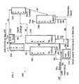
- the inventionfeatures a biomass material catalytic cracking system.
- the systemincludes a first riser, a second riser, a first stripper, a second stripper, a knock out drum, a regenerator, and a catalyst cooler.
- the systemfurther includes any one or more of the following components: a kneader, a cyclone, a tower, a second knock out drum, and a third riser.
- the preexisting catalytic cracking systemincludes a first riser, a second riser, a first stripper, a second stripper, a knock out drum, and a regenerator.
- FIG. 1illustrates an exemplary embodiment of piping and equipment design including two risers, two strippers, a catalyst cooler, a regenerator and a knock out drum.
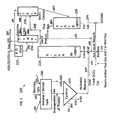
- FIG. 2illustrates an exemplary embodiment of piping and equipment design including a kneader, a cyclone, a riser, a catalyst cooler, a stripper, a regenerator and a knock out drum.
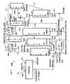
- FIG. 3illustrates an exemplary embodiment of piping and equipment design including a kneader, a cyclone, two risers, a catalyst cooler, two strippers, one regenerator and a knock out drum.
- FIG. 4illustrates an exemplary embodiment of piping and equipment design including a kneader, three risers, two strippers, one regenerator and two knock out drums.
- biomassescan include any biological material derived from living, or previously living, organisms.
- biomasses suitable for use in the process described hereincan include inedible materials, which do not compete with the food supply as well as materials that can be easily grown, or materials that are otherwise readily available, such as: grasses (including, for example, switch grass), saw dust, wood chips, wood bark, twigs, straw, corn stover, cotton linters, bagasse, and the like.
- biomassesinclude materials of photosynthetic origin (e.g., plants), having such as, for example, materials made predominately of cellulose, hemicellulose, or lignin.
- aspects of the inventionrelates to a process for organophilizing a particulated solid biomass material.
- the processmay include pretreating the biomass material such that the biomass material is physically compatible with liquid hydrocarbon material(s) (described in detail below).
- physical compatibilityit is meant that the solid biomass material may be efficiently carried by the liquid hydrocarbon material.
- reducing the particle size of the biomass processing to a sufficiently small sizepermits the biomass material to be evenly distributed in the liquid hydrocarbon material, and to be mixed, effectively suspended, or actually suspended in the liquid hydrocarbon material, or to form a stable suspension.
- the term “suspended”refers to the biomass material being physically compatible with the liquid hydrocarbon, and thus the biomass material may be mixed with the liquid hydrocarbon material or either effectively suspended, or actually suspended within the liquid hydrocarbon material. This step enables the biomass material to be physically compatible with, or otherwise efficiently carried by, the liquid hydrocarbon material.
- the preferred particle size to be suspendedvaries depending on a number of factors, including: the composition of the biomass material, the composition of the liquid hydrocarbon material, the velocity of the liquid hydrocarbon material, the temperature and pressure of the suspension, the material of the conduit (e.g., pipe or tank) holding the suspension, the amount of time the suspension is to remain together, and like considerations.
- the suspension of the biomass material and liquid hydrocarbon materialare contained within a pipe at a refinery and the biomass material is considered efficiently carried by the liquid hydrocarbon material so long as the pipe does not substantially plug after continued use.
- the biomassis converted using a biomass material catalytic system using one or more risers.
- the biomassis converted using a first and a second riser.
- the first risercan be operated at temperatures allowing the depolymerization of hemicellulose and cellulose wherein the second riser can be operated under higher severities conditions (e.g. higher temperatures and longer residence time) to process the remaining lignin material and intermediate material.
- the biomassis pre-treated to facilitate the liquefaction or thermolysis of the biomass components, such as lignin, hemicellulose and cellulose. Pre-treatment, such as selective chemical pre-cracking of the lignin polymer, facilitates the low temperature conversion of cellulose.
- the biomass materialis pretreated by mechanical processing, such as, for example, shredding, chipping, milling, kneading, grinding, and the like, until the mean average particle size of biomass material—as a whole—ranges from 1 mm to 10 cm, alternatively from 1 cm to 10 cm.
- mechanical processingsuch as, for example, shredding, chipping, milling, kneading, grinding, and the like.
- the solid biomass materialprior to the torrefaction, is mechanically treated to form particles having a mean particle size in the range of from 1 ⁇ m to 10 cm.
- the mean average particle size of each, individual, biomass materialranges from 1 ⁇ m to 10 cm, alternatively from 1 cm to 10 cm.
- an intimate mixture of the biomass material with a particulate inorganic catalyst materialis created, preferably, prior to the torrefaction process, when the solid biomass material is still relatively soft.
- Suitable methods for creating such intimate mixturesinclude mechanical process, such as milling, grinding, kneading, extruding, and the like.
- the biomass-catalyst mixturecan include an inorganic particulate material.
- An inorganic particulate materialcan be inert or catalytic.
- An inorganic materialcan be present in a crystalline or quasi-crystalline form.
- Exemplary inert materialsinclude inorganic salts such as the salts of alkali and alkaline earth metals. Although these materials do not necessarily contribute to a subsequent chemical conversion of the polymeric material, it is believed that the formation of discrete particles of these materials within the biomass can work as a wedge to mechanically break up or open the structure of the biomass, which can increase the biomass surface accessible to microorganisms and/or catalysts. In one embodiment, the breaking up or opening is facilitated by crystalline or quasi-crystalline particles.
- Inorganic particulate materialcan have catalytic properties.
- a catalytic inorganic particulate materialcan be a metal oxide or hydroxide such as an alumina, silica, silica aluminas clay, zeolite, ionic clay, cationic layered material, layered double hydroxide, smectite, saponite, sepiolite, metal hydroxyl salt, and the like.
- Carbonates and hydroxides of alkali metals, and the oxides, hydroxides and carbonates of alkali earth metalscan also have catalytic properties.
- Inorganic particulate materialcan include mixtures of inorganic materials.
- Inorganic particulate materialcan include a spent (resid) fluid catalytic cracking catalyst containing (thermally treated) layered material.
- Employing spent catalystcan involve reusing waste material.
- the spent catalystcan be pulverized into smaller particles to increasing dispersibility.
- Inorganic particulate materialcan also include sandblasting grit.
- Employing sandblasting gritcan involve reusing waste material, which can include particles of iron, and lesser quantities of other suitable metals such as nickel, zinc, chromium, manganese, and the like (e.g., grit from steel sandblasting).
- a catalytic metalcan be contacted with the biomass by various methods.
- the catalystis added in its metallic form, in the form of small particles.
- the catalystcan be added in the form of an oxide, hydroxide, or a salt.
- a water-soluble salt of the metalis mixed with the biomass and the inert particulate inorganic material in the form of an aqueous slurry.
- the biomass and the aqueous solution of the metal saltare mixed before adding the inert particulate inorganic material to facilitate the metal impregnating the biomass.
- the biomasscan also be mixed with the inert particulate inorganic material prior to adding the aqueous solution of the metal salt.
- an aqueous solution of a metal saltis mixed with the inert inorganic material, the material is dried prior to mixing it with the particulated biomass, and the inert inorganic material is thus converted to a heterogeneous catalyst.
- the biomass materialis impregnated with a solution of an inorganic material in a suitable solvent, prior to exposing the biomass material to the toasting temperature.
- a suitable solventfor aqueous liquids.
- preferred inorganic materialsinclude the carbonates and the hydroxides of alkali metals and earth alkaline metals, in particular the hydroxides and carbonates of sodium and potassium.
- the solid biomassis impregnated with a solution of a soluble inorganic material and intimately mixed with an insoluble, particulate inorganic material, prior to exposing the solid biomass to the toasting temperature.
- the steps of impregnating the solid biomass with a solution of an inorganic material and of intimately mixing the solid biomass with a particulate inorganic materialmay be combined, or may be carried out in sequence.
- Preferred soluble inorganic materialsinclude the hydroxides, carbonates, sulfates of sodium and potassium.
- Preferred insoluble, particulate inorganic materialsinclude layered anionic and cationic clay materials, transition metal oxides, alkali and alkaline earth oxides, hydroxides, hydroxycarbonates and carbonates, doped transition metal oxides with acidic ions, alumino-silicates, and, in particular, hydrotalcite-like materials and mixtures thereof.
- the biomassis contacted with a pressurized solvent at a temperature above its natural boiling point (e.g., atmospheric pressure).
- the pressurized solventis a liquid phase and swell the biomass.
- the solventis de-pressurized, causing rapid evaporation of the solvent.
- the rapid evaporationcan be referred as solvent explosion.
- the solvent explosioncan physically rupture the biomass material, thereby making is more accessible to a subsequent reaction.
- solventsexamples include ammonia, carbon dioxide, water and the like. If ether is used as the solvent, it can be referred to steam explosion. Steam explosion can be carried before or after demineralization, when combined with demineralization. For example, it may be advantageous to conduct demineralization after steam explosion because steam explosion pretreatment can make the minerals more accessible.
- the torrefaction processis used as a means to prepare the raw biomass before liquefaction conducted in a catalytic cracking reactor unit by converting soft/flexible raw biomass particles to harder/brittle particles, having higher density, which can be more easily ground to small particles consuming much less mechanical energy; and converting the surface properties of said particles to hydrophobic from hydrophilic. Therefore, the small organophilic (i.e., hydrophobic) particles become more miscible with oil and are suitable to mix with, for example, crude oil FCC-feed and can, this way, be co-processed in the FCC Unit.
- the small organophilic (i.e., hydrophobic) particlesbecome more miscible with oil and are suitable to mix with, for example, crude oil FCC-feed and can, this way, be co-processed in the FCC Unit.
- the biomass materialis subjected to torrefaction to render it more organophilic, i.e., less hydrophilic, and therefore to permit the biomass material to be evenly distributed in the liquid hydrocarbon material, and to be mixed, effectively suspended, or actually suspended in the liquid hydrocarbon material.
- the torrefaction stepenables the biomass material to be physically compatible with, or otherwise efficiently carried by, the liquid hydrocarbon material.
- the combination of reducing the particle size of the biomass material to a sufficiently small size and torrefying (described in detail below) the biomass materialpermits the biomass material to be evenly distributed in the liquid hydrocarbon material, and to be mixed, effectively suspended, or actually suspended in the liquid hydrocarbon material, which may enable the biomass material to be physically compatible with, or otherwise efficiently carried by, the liquid hydrocarbon material.
- the biomass materialmay be further pretreated, after mechanical processing, in a torrefaction process at a temperature between 80° C. and 400° C., alternatively between 80° C. and 200° C., alternatively between 110° C. and 200° C., alternatively between 200° C. and 400° C.
- torrefactionrefers to a heat treatment of the particulated solid biomass material in an oxygen-poor or a substantially oxygen-free atmosphere.
- toastingrefers to heat treatment carried out at temperatures between 80° C. and 300° C., or preferably between 110° C. and 200° C., or more preferably between 105° C. and 140° C.
- stingrefers to heat treatment carried out at temperatures between 300° C. and 400° C.
- a biomass materialis considered “toasted” when it is torrefied at a temperature between 80° C. and 300° C.
- a biomass materialis considered “roasted” when it is torrefied at a temperature between 300° C. and 400° C.
- the torrefaction processproceeds under atmospheric conditions.
- the torrefaction processproceeds in an oxygen-poor or substantially oxygen-free environment.
- the torrefactionis carried under an atmosphere containing less oxygen than does ambient air, containing less than about 22 volume percent oxygen, alternatively less than about 20 volume percent oxygen, alternatively less than about 21 volume percent oxygen, alternatively less than about 15 volume percent oxygen, alternatively less than about 10 volume percent oxygen, and alternatively less than about 5 volume percent oxygen.
- the torrefaction processproceeds in the presence of an inert gas, such as for example nitrogen or steam.
- the moisturewill escape from the biomass particles and form a steam blanket around the biomass material, thereby protecting it from atmospheric oxygen.
- the processis then conducted in a steam atmosphere at ambient pressure or at higher steam pressure.
- the processis carried out in air, as compared to in an atmosphere that is substantially oxygen-free.
- the biomass materialprior to the torrefaction process, is mixed with water, and introduced into a closed vessel, for example an autoclave.
- the amount of watercan range from 25 weight percent to 500 weight percent, based on the weight of the dry biomass material.
- the amount of wateris in the range of from 50 weight percent to 300 weight percent based on the weight of the dry biomass.
- the atmosphere surrounding the biomass materialis enriched in steam, creating an oxygen-poor atmosphere even though no oxygen escapes from the closed vessel.
- the torrefaction processcan then be carried out under autogenous pressure.
- the pressureis released by opening the vessel, or opening a release valve provided on the vessel.
- the pressure of the vesselis released while the biomass material remains at an elevated temperature, for example at or about the torrefaction temperature, which, as described, ranges from 80° C. to 400° C.
- the pressure releasecauses a rapid evaporation of water absorbed in the biomass material, thereby rupturing the structure of the biomass material and facilitating mechanical processing of the particulated biomass material as well as subsequent conversion reactions.
- the biomass materialcan be torrefied from several seconds to several hours, depending on a number of factors, including without limitation, the initial particle size of the biomass material, the desired particle size of the torrefied biomass material, the initial moisture content of the biomass material, the desired moisture content of the torrefied biomass material, the heating rate, the final desired temperature of the torrefied biomass material, and like considerations.
- the duration temperatureis short if the temperature is nearer the upper end of the range, particle size is small, and moisture content is low.
- the biomass materialcan be torrefied at 125° C. for about 25 minutes.
- the torrefied materialoffers several advantages.
- the torrefied materialhas a higher density, and greater flowability, making it easier to transport and store. Being more brittle, it is more readily ground to smaller particles. Particles obtained by milling or grinding torrefied material are more round (less needle-like) than particles obtained by grinding un-torrefied biomass material.
- the torrefied materialis generally hydrophobic and, as a result, has greater microbial stability.
- the torrefaction of the biomass materialcauses it to become relatively brittle, the amount of energy necessary to reduce the mean average particle size of the biomass material is greatly reduced.
- relatively large solid biomass particlesare used for the torrefaction, for example in the range of 1 cm to 10 cm.
- the mean average particle size of the biomass material—as a whole—following the torrefaction processranges from 1 ⁇ m to 1000 ⁇ m, alternatively from 10 ⁇ m to 500 ⁇ m, alternatively from 10 ⁇ m to 200 ⁇ m (“particulated biomass”).
- the biomass materialmay be further mechanically processed by, for example, shredding, chipping, milling, grinding, kneading, and the like, until the mean average particle size of the biomass material—as a whole—ranges from 0.1 ⁇ m to 1000 ⁇ m, alternatively from 1 ⁇ m to 500 ⁇ m, alternatively from 10 ⁇ m to 200 ⁇ m.
- the biomass materialis particulated by conveying biomass material in a stream of gas, and forcing the stream, with the biomass material, to collide with a surface, or with particles, of greater hardness than the biomass material.
- such a methodmay be carried out in a tubular device, or in a cyclone.
- gaseous materials and volatile organic compoundsare released from the biomass material.
- gases and volatile organic compoundsinclude carbon dioxide, acetaldehyde, formaldehyde, acetic acid, formic acid, methanol, carbon monoxide, and methane. It is desirable to capture these materials as they are released from the biomass.
- methane and methanolmay be used in the process for heating the biomass to the torrefaction temperature.
- carbon monoxidemay be used in a subsequent catalytic pyrolysis process as a reducing agent.
- Acetaldehyde, formaldehyde, acetic acid and formic acidare well known building blocks of valuable organic compounds.
- the torrefaction temperatureis chosen so as to avoid the formation of significant quantities of organic compounds that are liquid at room temperature, and contain 4 or more carbon atoms.
- the torrefaction temperaturecan be at or above 200° C.
- the torrefaction temperaturevaries with the nature of the biomass material (in particular the amount of ash or minerals present in the biomass material), the presence or absence of catalytic material in the biomass during the torrefaction step, and, if a catalytic material is present, the nature of the catalytic material.
- the solid biomass materialis converted into a fluidizable biomass/catalyst composite particles.
- the processcomprises the steps of (i) providing a particulated solid biomass material; (ii) forming a composite of the biomass material and a catalytic material; (iii) subjecting the biomass material to a thermal treatment at a torrefaction temperature at or above 200° C., and low enough to avoid significant conversion of the biomass material to liquid conversion products; and (iv) forming fluidizable particles from the biomass material.
- liquid conversion productsrefers to organic compounds resulting from the conversion of biomass that are liquid at room temperature and contain 4 or more carbon atoms.
- step (ii)may be carried out immediately prior to step (iii), or there may be one or more intermediate steps, such as drying and/or storing.
- the pre-torrefaction biomass materialis relatively soft as compared to the catalytic material.
- a solid catalytic materialreadily adheres and/or penetrates the biomass material if mechanical action is exercised on a mixture of the two materials, such as milling, grinding, or kneading.
- catalytic materialis insoluble. If the catalytic material is soluble it may be dissolved in a suitable solvent, and the resulting solution used to impregnate the biomass material.
- the torrefaction step (iii)is carried out before the formation of a composite of the biomass material and a catalytic material (step (ii)), that is, the biomass material is subjected to torrefaction before the composite of the biomass material and the catalytic material is formed. It will be understood that, in this embodiment, step (iii) may be carried out immediately before step (ii), or there may be one or more intermediate steps, such as cooling, grinding, storing, and the like.
- torrefactionmakes the biomass material brittle and tends to make the biomass material hydrophobic, which may make it difficult to impregnate the material with a solution of catalytic material, if the solvent is an aqueous liquid.
- a slurry or a solution of catalyst materialis spared onto particles of torrefied biomass material.
- the torrefaction step and the formation of a composite of the biomass material and a catalytic materialare carried out simultaneously.
- particles of biomass material and catalyst particlesmay be blended at ambient temperature, and heated together to the torrefaction temperature.
- the mixtureis subjected to agitation while being heated.
- biomasspasses through a gelatinous state, in particular if the torrefaction is carried out in a steam atmosphere, or if sufficient water is present in the biomass material to form a steam atmosphere around the particles. Catalyst particles readily adhere to the biomass particles while the latter pass through a gelatinous state.
- Some aspects of the inventionrelates to the fluidization of biomass materials.
- sphere-likerefers to particles having a length-to-diameter ratio of less than 3.
- Preferredare particles having a length-to-diameter ratio of less than 2. It is being understood that fully spherical particles have a length-to-diameter ratio of 1.
- the average length-to-diameter ratio of a particulated productcan be determined by any technique known in the art. For example, a photomicrograph of a representative sample of the particles may be analyzed using a scanning camera and an appropriate computer algorithm.
- fluidizationrequires reduction of the particle size of the biomass material.
- fluidization stepdoes not need to be carried out immediately following torrefaction step, in particular as torrefaction improves the storage properties of the biomass material.
- fluidizable particlesrefers to Group A particles and Group B particles according to the Geldart classification (see Geldart, Powder Technology 7, 285-292 (1973)). In some embodiments, Group A particles are preferred. In general, these conditions are met if torrefied biomass material is ground to a particle size between 10 ⁇ m and 1,000 ⁇ m, preferably between 30 ⁇ m and 400 ⁇ m and more preferably between 2 ⁇ m and 40 ⁇ m and most preferable less than 1 ⁇ m.
- a mineral-containing biomass materialis subjected to a demineralization treatment to form the biomass material, either prior to or after the torrefaction process.
- demineralization treatmentis the removal of at least part of the inorganic materials as may be naturally present in the biomass material.
- Many biomass materialscontain minerals that are catalytically active, and could interfere with subsequent conversion processes.
- the solid biomass feedstockmay contain from 1 weight percent to more than 20 weight percent minerals, generally referred to as “ash”. High ash contents are generally undesirable, as they can lead to uncontrolled catalytic reactions during the conversion process. Minerals present in the biomass material may foul refinery equipment, and may even poison catalysts used in refinery processes.
- Minerals present in the biomass materialcan also contribute to the hydrophilic nature of the biomass material, in which case their removal contributes to the organophilizing effect of the torrefaction treatment.
- the demineralization treatmentremoves all, or at least part of, the inorganic materials contained within the biomass material.
- the demineralization treatmentincludes extraction of minerals from the biomass material with an aqueous solvent.
- Suitable aqueous solventscan include water or aqueous solutions of an acid such as, for example, and without limitation: a mineral acid including sulfuric acid, nitric acid, and hydrochloric acid, an organic acid including a carboxylic acid such as formic acid, acetic acid, propropionic acid, and the like or mixtures thereof.
- hydrochloric acidis used as it is easily removed from the biomass by heating.
- the aqueous solventincludes a chelant such as, for example and without limitation, citric acid.
- the aqueous solventhas a pH of less than about 7, alternatively the aqueous solvent has a pH between 2 to 5.
- the demineralization treatmentincludes contacting the biomass material with the aqueous solvent, and subsequently removing at least part of the aqueous solvent.
- the demineralization treatmentincludes swelling the solid biomass material with the aqueous solvent (“swelling”), and subsequently removing at least part of the aqueous solvent by mechanical action (“dewatering”), such as, for example and without limitation, pressing the swollen biomass material in a filter press.
- the swelling and dewateringis carried out in a kneader.
- the biomass materialis swelled and dewatered once, or repeatedly, in order to obtain a biomass material having a suitable mineral content.
- the biomass materialis swelled and dewatered multiple times, and after the final swelling step, the biomass material—still in its swollen, or substantially swollen, state—may introduced into the torrefaction process.
- Suitable mineral contentsinclude less than about 2.5 weight percent minerals, alternatively less than about 1 weight percent minerals, alternatively less than about 0.5 weight percent minerals, based on the total weight of the biomass material.
- Obtaining biomass with suitable mineral contentcan be accomplished by a judicious selection of the solid biomass material, or subjecting the biomass material to a demineralization pretreatment, or both.
- the methodincludes agitating solid biomass particles, to reduce a size characterizing at least a portion of the particles. See PCT publication WO2010/002792 which is incorporated herein by reference in its entirety.
- agitatingis facilitated by fluid conveyance, including, without limitation, by gas flow or pneumatic conveyance.
- Agitatingcan be conducted in a vertical vessel, such as a riser or downer.
- An agitatorcan include a conveyor, a riser, or downer.
- a riser (up flow) or a downer (down flow)can be, for example, a hollow vertical vessel terminating in a larger diameter vessel, which houses high velocity (e.g., about 60-80 m/s or 18-24 m/s) cyclones that may or may not be physically connected to the riser termination point.
- the height of a riser or downercan be, for example, between about 15 ft (5 m) and about 60 ft (18 m) and the diameter can be, for example, between about 1 ft (0.3 m) and about 4 ft (1.2 m).
- Agitatingcan be facilitated by a gas (e.g., gas can convey the particles such that they are abraded or ground by other particles, catalyst, and/or inorganic particulate material).
- the gascan be one or more of air, steam, flue gas, carbon dioxide, carbon monoxide, hydrogen, and hydrocarbons (e.g., methane).
- the gascan be a gas having a reduced level of oxygen (compared to air) or can be substantially oxygen-free.
- an agitatoris a mill (e.g., ball or hammer mill) or kneader or mixer (e.g., for mechanical, as opposed to pneumatic, agitation).
- agitatingincludes causing the solid biomass particles to be conveyed at a velocity of greater than about 1 m/s.
- the velocitycan be measured relative to a vessel in which the particles are conveyed.
- Agitatingincludes causing the solid biomass particles to move at a velocity of greater than about 10 m/s.
- Agitatingincludes causing at least a portion of the solid biomass particles to move at a velocity of greater than about 100 m/s.
- An agitatorcan be adapted to cause the solid biomass particles to move at a velocity of greater than about 1 m/s, greater than about 10 m/s, and/or greater than about 100 m/s.
- velocitiesinclude velocities of greater than about 5 m/s, 25 m/s, 50 m/s, 75 m/s, 125 m/s, 150 m/s, 175 m/s, 200 m/s, 225 m/s, or 250 m/s.
- the velocitymay be within a range selected from the group consisting of 10 m/s to 20 m/s, 20 m/s to 30 m/s, 30 m/s to 40 m/s, 40 m/s to 50 m/s, 50 m/s to 60 m/s, 60 m/s to 70 m/s, 70 m/s to 80 m/s, 80 m/s to 90 m/s, and 90 m/s to 100 m/s.
- the velocitycan be about 10 m/s, 20 m/s, 30 m/s, 40 m/s, 50 m/s, 60 m/s, 70 m/s, 80 m/s, 90 m/s, or 100 m/s.
- the velocitycan be greater than about 10 m/s, 20 m/s, 30 m/s, 40 m/s, 50 m/s, 60 m/s, 70 m/s, 80 m/s, 90 m/s, or 100 m/s.
- agitating solid biomass particlesto reduce a size characterizing at least a portion of the particles, is facilitated by agitating solid biomass particles together with a material that is harder than the biomass.
- the materialis a catalyst or another inorganic particulate material.
- the amount of size reduction, and thus the size of the resulting solid biomass particlescan be modulated by the duration of agitation and the velocity of agitation. Other factors such as the relative hardness of the catalyst or another inorganic particulate material, the dryness (e.g., brittleness) of the solid biomass particles, and the method/vessel(s) in which agitation occurs also modulate the amount of size reduction.
- the catalystcan become embedded in the biomass particles and/or the biomass particles can become embedded in the catalyst, which can facilitate catalytic conversion of the biomass.
- agitatingcan facilitate formation of a mechano-chemical interaction between at least a portion of the catalyst and at least a portion of the solid biomass particles, which can facilitate catalytic conversion of the biomass.
- Agitationcan be carried out at an elevated temperature, for drying the biomass.
- An elevated temperaturecan be a temperature sufficient to dry the biomass, for example, between about 50° C. and about 150° C., or below about 200° C. Higher temperatures can be used, for example, where an agitating gas is oxygen-poor or substantially oxygen-free. Agitation can also be carried out at ambient temperature with dried biomass. Drying increases the hardness of the biomass particles, making the particles more susceptible to size reduction.
- Agitationcan be carried out by various different methods and in various different vessels.
- the agitationin order of increasing abrasion, can be carried out in a fluid bed, a bubbling or ebullient bed, a spouting bed, or a conveyor.
- agitationis carried out by fluid conveyance, including without limitation by gas flow or pneumatic conveyance.
- agitationis carried out in a riser or a downer.
- the kneaderis an extruder, mill, or grinder.
- the kneaderis a screw extruder, or a ball mill or grinder.
- a kneaderkneads the solid biomass particles and the catalyst, to make at least a portion of the solid biomass particles accessible to at least a portion of the catalyst.
- the kneadercan operate at greater than ambient temperature.
- the kneadercan be heated and/or operate in presence of heated gas (e.g., steam)
- the kneaderemploys a solvent.
- the solventcan be water, an alcohol (e.g., ethanol or glycerol), a bio-oil or another product from the conversion of the biomass, a liquid acid, an aqueous acid or base, liquid CO 2 , and the like.
- the solventis water (e.g., added water and/or water inherent in the biomass), which can be selected for its availability, low cost, and/or ease of handling.
- the solventis a liquid produced during the subsequent conversion of the biomass, which can be selected for its availability.
- a solventcan improve penetration of a catalyst into biomass because a dry biomass can be more difficult to penetrate.
- Solventscan be removed (e.g., by drying) prior to subsequent processing and/or conversion.
- a kneadercan remove at least a portion of a solvent absorbed in a biomass (e.g., by mechanical action and draining).
- Embodiments employing a kneader and a solventcan reduce the ash and/or mineral and/or metal content of the biomass.
- the biomassis kneaded with one or more solid catalyst and/or inorganic particulate material.
- the biomassis kneaded with a dissolved and/or suspended catalyst.
- the dissolved and/or suspended catalystcan be used together with one or more solid catalyst and/or inorganic particulate material. Kneading can be continued and/or repeated to produce a biomass-catalyst mixture having the desired properties (e.g., particle size and/or degree of sensitization).
- liquid compositioncomprising a liquid suspension medium having suspended therein small particles of a biomass material and small particles of an inorganic material, said composition being stable.
- liquid compositionsare stable in the sense that the solid and liquid phases do not separate within the time necessary to transport them to a location or unit where they can be further processed.
- the torrefied, particulated biomass materialis suspended within a liquid hydrocarbon material.
- the torrefied, particulated biomass materialis suspended a liquid hydrocarbon material by feeding the torrefied, particulated biomass material and the liquid hydrocarbon material into a high shear mixer.
- the liquid hydrocarbon materialmay be obtained from a refinery stream.
- the term “refinery stream”refers herein to any liquid hydrocarbon mixture used as a feedstock in, or produced by, a unit operated in an industrial petroleum refinery.
- suitable liquid hydrocarbon materialsinclude: naphtha, gasoil, light cycle oil, heavy cycle oil, atmospheric residuum, vacuum residuum, FCC bottoms, aromatic furfural extract, slurry oil, decant oil, de-asphalted oil, crude oil, atmospheric tower bottoms, atmospheric gas oil, vacuum gas oil, light vacuum gas oil, heavy vacuum gas oil, clarified slurry oil, hydrotreated vacuum gas oil, hydrotreated de-asphalted oil, coker gas oil, hydrotreated coker gas oil, and mixtures thereof.
- refinery streamcan be characterized by their physical properties such as gravity, viscosity, and boiling point.
- naphthacan be taken as intermediate materials inside a refinery to be eventually blended as finished gasoline.
- the hydrocarbon mixturecan come directly from crude (e.g. straight run) or after cracking (e.g. FCC, hydrocracking, and coker), reforming, isomerization, and alkylation reactions have taken place.
- naphthacomprises, for example, molecules having at least 5 carbon atoms (C5) to up to 12 carbon atoms (C12), with a final boiling point around 220° C.
- the composition mixturecomprises compounds generally having at 8 to 10 carbon atoms (C8 to C10) and extending to 14 carbon atoms (C14) with a final boiling point below 220° C.
- naphthais a mixture of four specific families of compounds, paraffins, olefins, naphthenes, and aromatics and may ultimately be composed of more than 400 compounds. Depending on the process used, the formation of one or two of the families of compounds is favored. For example, straight run naphtha is generally paraffinic in nature and contains no olefins.
- the streamcan be manipulated in isomerization and reforming units that preferentially make isoparaffins and aromatics, respectively.
- ATM bottomsare generally an intermediate stream that is sent to the vacuum distillation column.
- ATM bottoms mixturecan be composed of varying degrees of paraffins, aromatics or naphthenes and can be composed of hundreds of compounds having an initial boiling point in excess of 290° C. and a final boiling over 560° C.
- the particulated biomass materialis preferably physically compatible with the liquid hydrocarbon material.
- the particulated biomass materialis suspended in the liquid hydrocarbon material to permit processing of the suspension in a refinery unit operation.
- the organophilized solid biomass particlesis suspended in the liquid hydrocarbon material, such as a refinery stream, by any suitable method.
- organophilized solid biomass particles in the desired particle size rangecan be fed into a high shear mixer together with a stream of refinery hydrocarbons.
- the suspensionis sufficiently stable to permit processing of the suspension in a refinery unit operation.
- the suspensionis continuously agitated, and in still further embodiments, the residence time of the refinery stream in the refinery unit is very short, for example less than about 5 minutes, alternatively less than about 1 minute, alternatively less than about 30 seconds, alternatively less than about 15 seconds, alternatively less than about 5 seconds, alternatively less than about 1 second.
- the particulated biomass material and liquid hydrocarbon suspensioncontains from 1 weight percent to 40 weight percent, alternatively from 5 weight percent to 25 weight percent, by weight of the suspension, particulated biomass material.
- the mean particle size of the particulated solid biomass material in the suspensionpreferably is in the range of 1 ⁇ m to 1000 ⁇ m.
- the liquid hydrocarbon materialis preheated up to about 400° C. or 500° C., or higher, prior to the introduction of the biomass material into the liquid hydrocarbon material, and then the suspension is fed into a unit.
- the particulated biomass material present in the suspensioncan receive additional heat treatment during this preheating step, which results in further organophilization of the biomass material.
- suitable unitsincludes, for example, a pyrolysis reactor, a fluid catalytic cracking unit, a thermofor catalytic converter, a delayed coker, a fluid coker, a solvent deasphalting unit, a hydroprocessing unit, and a hydrocracking unit.
- the particulated biomass materialis introduced to the liquid hydrocarbon material, without preheating the liquid hydrocarbon material, and the suspension is preheated up to about 400° C. or 500° C., or higher, prior to being fed into the unit.
- Such heat treatmentis carried out at the desired preheating temperature appropriate for the subsequent processing in the refinery unit, or at a lower temperature.
- the particulated biomass materialis preheated to a temperature of about 300° C., or less, prior to being introduced to the liquid hydrocarbon material, and then the suspension is preheated to about 400° C. or 500° C., or higher, prior to being fed into the unit.
- the suspension of particulated biomass material and liquid hydrocarbon materialis introduced together with a heat carrier within the unit.
- the heat carrierhas a temperature ranging of at least 450° C., preferably at least 550° C., more preferably at least 600° C.
- the heat carriermay be an inert material, such as, for example, sand. A material is considered “inert” in this context if it does not catalyze the conversion of solid biomass material to liquid products.
- the heat carrieris, or otherwise contain, a catalyst.
- catalystas used herein means any material that catalyzes the conversion of solid biomass material to liquid products.
- suitable catalystscan have widely varying chemical properties, and preferable catalysts may have specific surface areas (as measured by nitrogen adsorption using the BET method) ranging from 1 m 2 /g to 400 m 2 /g, alternatively from 5 m 2 /g to 100 m 2 /g, alternatively from 5 m 2 /g to 50 m 2 /g.
- suitable catalystsinclude water-insoluble catalysts.
- the catalytic materialis an acidic material.
- Suitable acidic materialsinclude mineral acids, such as nitric acid, hydrochloric acid, phosphoric acid, and sulfuric acid.
- Solid acidic materialsmay also be used, such as ZSM-5, HZSM-5, super acids, transition metal oxides (Al, Ti, Zr, etc) doped with acidic ions (salts), such as sulfates, chlorides, phosphates, etc.
- the catalystscomprise a solid acid, such as, for example, a zeolite including ZSM-5 and zeolite-Y.
- the catalystmay comprise a solid base, such as, for example, a hydrotalcite or a calcinated hydrotalcite, a hydrotalcite-like material or a calcinated hydrotalcite-like material, a clay or a calcinated clay, a layered hydroxy salt or a calcinated layered hydroxy salt, a mixed metal oxide or a calcinated mixed metal oxide, or a mixture thereof.
- a solid basesuch as, for example, a hydrotalcite or a calcinated hydrotalcite, a hydrotalcite-like material or a calcinated hydrotalcite-like material, a clay or a calcinated clay, a layered hydroxy salt or a calcinated layered hydroxy salt, a mixed metal oxide or a calcinated mixed metal oxide, or a mixture thereof.
- basic catalytic materialsinclude alkali metal oxides and hydroxides, alkali metal carbonates, earth alkaline metal oxides and hydroxides, (in particular, NaOH, KOH, Na 2 CO 3 , and K 2 CO 3 ), earth alkaline metal carbonates, layered mixed hydroxides, cationic layered materials, hydrotalcite and hydrotalcite-like materials, combinations of an alkali metal carbonate and a hydrotalcite-like material (including hydrotalcite per se), and mixtures thereof.
- calcinated productscan be used to reduce the coke yield of the conversion of the suspended biomass material into fuel.
- the catalystcomprises an amphoteric material, such as alumina, or a neutral material (such as coke, for example, petroleum coke).
- the catalystmay be a conventional FCC catalyst, such as, without limitation, vacuum gas oil (VGO) catalysts, or a catalyst having hydrotreatment activity, or hydrogenation activity, including without limitation Co/Mo, Ni/Mo, Co/W, and Ni/W hydrotreatment catalysts, as well as such catalysts in sulfided form, supported noble metal catalysts, and supported transition metal catalysts (for example iron, zinc, copper, nickel, and manganese).
- Converting biomass feedstocksincludes techniques from biomass and/or petroleum processing.
- the materialmay be subjected to a conversion process to form liquid and/or gaseous products.
- a conversion processto form liquid and/or gaseous products.
- processesinclude pyrolysis, biomass catalytic cracking (e.g., biomass catalytical cracking (BCC), fluid catalytic crackling (FCC type processes adapted from conventional petrochemical processing), hydrothermal upgrading, and gasification.
- Some aspects of the inventionrelate to a catalytic cracking process comprising converting the fluidizable particles made by the present process in a fluidized bed reactor.
- catalytic materialis already present in the biomass material, it may not be necessary to add additional catalyst. It may be desirable to add a heat carrier material in order to quickly heat the biomass material to the desired conversion temperature.
- the heat carrier materialmay be a particulate catalyst material, a particulate inert material, or a mixture of a particulate catalyst material and a particulate inert material as discussed above.
- the conversionis carried out at a temperature above the torrefaction temperature of step (iii), and below 550° C.
- the preferred catalytic conversion temperatureis in the range of from 300° C. to 450° C.
- Some aspects of the inventionrelates to the liquid refinery product comprising liquid organic compounds resulting from a conversion of solid biomass material.
- the particulated biomass material suspended within the liquid hydrocarbon materialmay be converted, changed, or otherwise reacted, into fuel within the unit.
- the conversion, change, or reaction within the unitmay be conducted in the presence of molecular hydrogen.
- oxygenis removed from the biomass materials by hydrodeoxygenation.
- hydrogenis used to efficiently convert oxygen into water. Accordingly, uses of the methods includes transfer of hydrogen from the hydrogen source (e.g., refinery feedstocks, hydrogen gas or a combination thereof) to biomass materials.
- the torrefied and ground biomass materialcontains an additive/catalyst before being mixed with the FCC-oil feed to be co-processed in the FCC-Unit. Yet in other embodiments, the torrefied and ground biomass material does not contain an additive/catalyst before being mixed with the FCC-oil feed to be co-processed in the FCC-Unit.
- the fuelmay be used as gasoline, as a feedstock for gasoline blending, as diesel fuel, as a basis for blending a diesel fuel, as jet fuel, as a basis for a jet fuel, as a feedstock for the petrochemical industry, and in connection with other similar uses.
- These liquid refinery productsoffer the advantage of a lower carbon footprint, as compared to purely petroleum based refinery liquids, and such fuels may have a higher heating value, as compared to ethanol/gasoline blends, which may result in a variety of benefits, including without limitation, increased gas mileage to the consumer.
- At least one of the first reaction vessel and the second reaction vesselinclude a riser.
- At least one of the first and second conventional refinery unitscan be a fluid catalytic cracking unit, a fluid or delayed coking unit, a fluid catalytic cracking pretreater unit, a resid HT unit, a deasphalting unit, a lube oil HT unit, a hydrocracker, an ethylene polymerization unit, a propylene polymerization unit, or an ebullating bed.
- the first conventional refinery unitcan be a riser.
- methods, apparatuses, and/or kitsinclude separating at least a portion of the liquefied biomass feedstock into a hydrocarbon fraction for co-processing with the conventional feedstock and an oxygenated fraction. At least a portion of the liquefied biomass feedstock can be de-oxygenated. Oxygen in the processed biomass feedstock can be retained in a product stream, without substantially converting the oxygen to H 2 O, CO, or CO 2 . Oxygen in the processed biomass feedstock can be selectively converted to H 2 O, CO, or CO 2 by controlling at least one of catalyst type and reaction temperature.
- methods, apparatuses, and/or kitsinclude a heat exchanger, to heat or cool at least one of the refinery units or recycled catalyst, to modulate a temperature of at least one of the refinery units.
- a fresh catalyst feedfor adding fresh catalyst after the agitating and the providing steps, can modulate a temperature in at least one refinery unit.
- methods, apparatuses, and/or kitsinclude (i) a third conventional refinery unit, where the first, second, and third units can operate at independently selected temperatures and catalysts, to optimize product selectivity; and (ii) a product separation system, where a product from each unit can be independently separated into one or more of a fraction to be recycled for further processing, a fraction to used as a feedstock for a conventional refinery unit, and a fraction to be used as a specialty chemical.
- the liquefied biomass feedstockis between 1 weight percent and 100 weight percent of the biomass-conventional feedstock.
- the liquefied biomass feedstockcan be between 5 weight percent and 50 weight percent of the biomass-conventional feedstock.
- the liquefied biomass feedstockcan be between 10 weight percent and 20 weight percent of the biomass-conventional feedstock.
- methods, apparatuses, and/or kitsinclude a first conventional refinery unit adapted for liquefying the biomass or the biomass-catalyst mixture to produce a liquefied biomass feedstock.
- Methods, apparatuses, and/or kitscan include retrofitting a preexisting conventional refinery unit for liquefying the biomass or the biomass-catalyst mixture to produce a liquefied biomass feedstock.
- Methods, apparatuses, and/or kitscan also include retrofitting a pre-existing second conventional refinery unit for co-processing at least a portion of a liquefied biomass feedstock and a conventional feedstock.
- Methods, apparatuses, and/or kitscan also include integrating the conditioning vessel and the system into the conventional refinery for co-processing the biomass feedstock and the conventional feedstock. Methods, apparatuses, and/or kits can also include providing a first conventional refinery unit adapted for liquefying the biomass or the biomass-catalyst mixture to produce a liquefied biomass feedstock.
- methods, apparatuses, and/or kitscan include instructions. Instructions can be for retrofitting a preexisting first conventional refinery unit for liquefying the biomass-catalyst mixture to produce a liquefied biomass feedstock. Instructions can be for retrofitting a preexisting second conventional refinery unit for co-processing at least a portion of a liquefied biomass feedstock and a conventional feedstock.
- methods of modifying a preexisting catalytic cracking systemwherein the preexisting catalytic cracking system has a first riser, a second riser, a first stripper, a second stripper, a knock out drum, and a regenerator.
- the methodcomprises wherein the method comprises modifying the piping and instrumentation of the preexisting catalytic cracking system to accommodate a catalyst cooler; installing a catalyst cooler in the preexisting catalytic cracking system; and modulating the operating parameters of one or more components of the preexisting catalytic cracking system to accommodate biomass material catalytic cracking system.
- FIGS. 1-4illustrates exemplary systems for preparing and processing biomass with catalyst.
- FIG. 1illustrates a biomass material catalytic cracking system 100 adapted for processing biomass material.
- the catalytic cracking system 100may include at least the following: a first riser 105 , a second riser 110 , a first stripper 115 , a second stripper 120 , a knock out drum 125 , a regenerator 130 , and a catalyst cooler 135 to optimize bio-oil yield.
- first riser 105 , second riser 110 , first stripper 115 , a second stripper 120 , first knock out drum 125 , and regenerator 130may be part of a preexisting catalytic cracking system (not shown).
- the preexisting catalytic cracking system (not shown)may be retrofitted for processing biomass material by, for example and without limitation: (1) adding the second riser 110 ; (2) modifying the piping and instrumentation design to accommodate the second riser 110 ; or (3) modulating the operating parameters of one or more components of the preexisting catalytic cracking system (not shown).
- the first riser 105is operated under conditions appropriate to deoxygenate and liquefy biomass and the second riser 115 is operated under conditions appropriate to convert a mixture of the biomass and the liquid hydrocarbon into bio fuels.
- the catalytic cracking systemconverts the biomass material into fluidizable biomass/catalyst composite particles that can be processed in refinery units or suspended in a refinery feed stream.
- the first riser 105may receive biomass material through a biomass inlet line 140 and a catalyst through a first catalyst line 143 . Suitable catalysts are described in detail above.
- the first riser 105may also receive a gas (for example, steam, flue gas, and/or wet gas) through a first gas line 146 , which may heat in part the first riser 105 .
- a gasfor example, steam, flue gas, and/or wet gas
- the biomass inlet line 140 , the first catalyst line 143 , and the first gas line 146may each be directly connected to the first riser 105 .
- the biomass inlet line 140 , the first catalyst line 143 , and the first gas line 146may each be directly connected to a first riser feed line 149 , and the first riser feed line 149 may be directly connected to the first riser 105 .
- the first riser 105may de-water and/or de-oxygenate the biomass material.
- the first riser 105may be operated at about 105° C. if it is used for dewatering and particle size reduction, or at about 350° C. if it is used for deoxygenation.
- the first gas line 146may agitate the biomass material and the catalyst, providing a velocity to at least a portion of the biomass material sufficient to reduce the particle size of at least some of the biomass material.
- the resulting biomass materialmay have an average particle size ranging from about 1 ⁇ m to about 1000 ⁇ m, and individual particle sizes of the biomass material may range from about 1 ⁇ m to about 1500 ⁇ m, alternatively from about 200 ⁇ m to about 500 ⁇ m.
- the first riser 105may be operated at relatively low temperature, which may facilitate conversion and product selectivity of the biomass material to liquefied biomass feedstock.
- the first riser 105is operated at relatively low temperatures to effect selective liquefaction (or thermolysis) of cellulose and hemicellulose which depolymerize at lower temperatures.
- the cracking of cellulose and hemicellulosewill lead to gas production (CO, CO 2 , H 2 O, H 2 ) and light hydrocarbons, lowering liquefaction yields.
- the first riser 105is operated at temperatures below about 350° C.
- the temperature range of the first riseris dependent on the biomass pretreatment and catalyst protocol used.
- the product vapors, residual biomass solids and catalyst solidsmay exit the first riser 105 and enter the first stripper 115 through a first stripper feed line 152 .
- the first stripper 115may fluidize the catalyst and residual biomass solids and strip hydrocarbons between particles of solids and from the surface of the solids.
- steam(not shown) may be fed into the first stripper 115 through a steam feed line (not shown) to facilitate fluidization of the catalyst residual biomass solids and/or stripping of hydrocarbons from the surface from their surfaces.
- the stripped product vapors and steammay exit the first stripper 115 and enter the knock out drum 125 through a first knock out drum feed line 155 .
- the knock out drum 125may cool and liquefy at least a portion of the gas fraction, which may allow the aqueous phase and the hydrophobic to separate.
- condensable vaporsmay be removed through a knock out drum exit line 158 .
- the spent catalystmay be fed through a first regenerator feed line 161 into the regenerator 130 .
- the product gases and steam from the second stripper 120may be fed through line 164 into the knock out drum 125 .
- the hydrophobic phasemay be separated as a liquid product (e.g., fuels, specialty chemicals, other intermediates) from the aqueous phase.
- Non-condensable vaporsexit the knock out drum 125 through line 167 and include, but not limited to, light gas, liquefied petroleum gas, as well as oxygenated gases (such as for example H 2 O, CO, CO 2 ).
- Non-condensable gasesmay be separated and used, stored, sold, or recycled.
- the oxygenated gasesmay be used to facilitate algae growth, which—without wishing to be bound by the theory—may have the benefit of reducing greenhouse gas/carbon emissions.
- spent catalyst and residual biomass separated in first stripper 115may exit the first stripper and enter the second riser 110 through a first stripper exit line 170 .
- Conventional feedstock(described above) may additionally be fed into the second riser 110 through a second riser feed line 173 .
- the second riser 110may co-process the liquefied biomass feedstock and the conventional feedstock.
- the biomass materialis pretreated such that it may be suspended in a liquid hydrocarbon material upon its introduction into the second riser 110 .
- the second riser 110may additionally receive, and be heated by, hot catalyst from regenerator 130 through line 182 .
- the second riser 110may additionally receive lift gas (e.g., steam, flue gas, wet gas).
- lift gase.g., steam, flue gas, wet gas.
- the second riser 110may be operated at temperatures above about 400° C.
- the second riser 110may be operated in essentially the same manner as a conventional reactor (i.e., a reactor designed for processing conventional feedstock, not liquefied biomass feedstock).
- the residual biomass feedstock fed into the second riser 110 through the first stripper exit line 170may be between 1 weight percent and 100 weight percent, alternatively between 5 weight percent and 50 weight percent, alternatively between 10 weight percent and 20 weight percent, of the biomass-conventional feedstock used during co-processing.
- the products and spent catalyst from the top of the second riser 110may be fed into the second stripper 120 through a second stripper inlet line 176 .
- stripping in the second stripper 120may be facilitated by steam.
- the product vapors leaving stripper 120may include hydrocarbons, stripped from the surface of the catalyst, and steam.
- the operating parameters of the first stripper 115 and the second stripper 120may be the same, or independently chosen.
- the riser and stripersrun under adiabatic conditions.
- the strippers, 115 and 120may be operated within the operating parameters of a conventional catalytic cracking system (for example between about 450° C. and about 550° C.).
- the strippers 115 and 120may be operated at similar or lower temperatures than the risers.
- the strippersmay be operated at temperatures of about 10° C. to about 50° C. lower than the risers.
- the regenerator 130may receive spent catalyst from the second stripper 120 through the regenerator feed line 161 .
- the catalystis regenerated in the regenerator 130 .
- the second stripper 120may increase product yield, decrease coke, decrease flue gas, and decrease the necessary regenerator temperature because it decreases the amount of hydrocarbons that enter, and are thus burned in, the regenerator 130 .
- the regenerator 130may produce flue gas, and may be used in other portions of the system.
- the hot regenerated catalystmay be fed from the regenerator 130 into the catalyst cooler 135 through a catalyst cooler feed line 185 .
- the catalyst cooler 135cools the catalyst.
- the cooled catalystmay be reintroduced into the first riser 105 through the first riser feed line 149 .
- FIG. 2illustrates a second catalytic cracking system 200 adapted for processing biomass materials.
- the second catalytic cracking system 200may include at least the following: a riser 210 , a stripper 220 , a knock out drum 225 , a regenerator 230 , a kneader 240 , a cyclone 245 , and a tower 250 .
- one or more of the riser 210 , stripper 220 , knock out drum 225 , a regenerator 230can be part of a preexisting catalytic cracking system (not shown).
- the preexisting catalytic cracking systemmay be retrofitted for processing biomass material by, for example and without limitation: (1) adding the kneader 240 , cyclone 245 , and tower 250 ; (2) modifying the piping and instrumentation design to accommodate the kneader 240 , cyclone 245 , and tower 250 ; or (3) modulating the operating parameters of one or more components of the preexisting catalytic cracking system (not shown).
- the kneader 240may receive the biomass material through a first kneader feed line 255 .
- the biomass materialmay be kneaded within the kneader 240 .
- the kneadermay also receive a solvent (for example and without limitation, water or ethanol) through a second kneader feed line 258 .
- the solventmay facilitate removal of impurities, such as ash, minerals, and metals, from the biomass material. At least a portion of the solvent, and/or other liquid intrinsic to unprocessed biomass material, may be removed from the biomass material in the kneader 240 .
- the kneader 240may additionally receive a catalyst through a third kneader feed line 261 .
- the kneader 240may knead the biomass material such that at least a portion of the biomass material is accessible to at least a portion of the catalyst. In this manner, the kneader 240 may produce biomass material “activated” for catalytic conversion (“activated biomass material”). In some embodiments, the kneader 240 may reduce the particle size of the biomass material.
- Kneaded, or activated, biomass materialmay be fed from the kneader 240 through a cyclone feed line 264 into cyclone 245 .
- the kneaded, or activated, biomass materialmay be agitated by gas, such as for example air, fed into the cyclone 245 through a cyclone air feed line 267 .
- the agitationmay further reduce the particle size of the biomass material.
- the cyclone 245may dry the activated biomass material, thereby removing water and solvent through a cyclone drain line 273 .
- the biomass materialmay be dried by either heating the biomass material with a hot gas, such as air fed into the cyclone 245 through a cyclone air feed line 267 , or mechanical action.
- a hot gassuch as air fed into the cyclone 245 through a cyclone air feed line 267
- the particle size of the biomass materialmay be reduced to a size sufficient to be dissolved or suspended in a liquid feedstock (described above) and introduced directly into the second riser 210 through a second riser feed line 270 .
- the biomass materialare fed into a kneader after receiving cyclonic treatment.
- the riser 210may receive biomass material, and optionally activated biomass material, from the cyclone 245 through the riser inlet line 270 .
- the individual activated biomass materialhave sizes small enough that the activated biomass material flows, and can be gravity-fed into the riser 210 .
- the biomass materialmay have an average particle size ranging from about 250 ⁇ m to about 1000 ⁇ m, and individual particle sizes of the biomass material may range from about 1 ⁇ m to about 1500 ⁇ m, alternatively from about 200 ⁇ m to about 500 ⁇ m, upon its introduction into the riser 210 .
- the riser 210also receives a liquid hydrocarbon material such as conventional feedstock through a riser feed line 275 .
- the riser 210may co-process the activated biomass material feedstock and the liquid hydrocarbon material.
- the biomass materialis pretreated such that it may be suspended in a liquid hydrocarbon material upon its introduction into the riser 210 .
- the riser 210may receive, and further process, a liquid fraction recycled from the tower 250 from a liquid fraction feed line 271 .
- the liquid fractionmay be recycled from the tower 250 through feed line 271 which may be attached to riser feed line 275 .
- Riser 210may receive and be heated by, hot catalyst from the regenerator 230 though a riser hot catalyst feed line 276 .
- Riser 210may additionally receive, and be heated by, a hot gas such as steam, non-condensable product gas or flue gas, through a riser hot gas feed line 296 .
- Riser 210may receive, and be cooled by, relatively cold, fresh catalyst through a riser cold catalyst feed line 281 .
- riser 210may operate at temperatures above about 400° C., alternatively between 450° C. and 550° C. In an embodiment, and without wishing to be limited by the theory, riser 210 may be operated essentially as a conventional reactor.
- Stripper 220may receive product vapors and spent catalyst from the riser 210 through a stripper feed line 285 . Stripper 220 may fluidize the catalyst and strip hydrocarbons between particles of the catalysts and from the surface of the catalyst. In an embodiment, steam (not shown) may be fed into the stripper through a steam feed line (not shown) to facilitate fluidization of the catalyst and/or stripping of hydrocarbons from the surface of the catalyst.
- the spent catalystmay be fed through a regenerator feed line 287 into the regenerator 230 .
- the stripped product vapors and steammay exit the stripper 220 and enter knock out drum 225 through knock out drum feed line 291 .
- knock out drum 225may cool and liquefy at least a portion of the gas fraction of the stripped catalyst and biomass material, which may allow the aqueous phase and the hydrophobic to separate.
- the aqueous phasee.g., water
- gas and/or liquid fractionmay be fed into the tower 250 through knock out drum exit line 294 .
- the incondensable vaporsseparate within knock out drum 225 and may be removed as desirable, unliquefied, products, including but not limited to light gas, liquefied petroleum gas, as well as oxygenated gases (such as for example H 2 O, CO, CO 2 ), through knock out drum product line 297 .
- the desirable, unliquefied productsmay be separated and used, stored, sold, or recycled.
- the oxygenated gasesmay be used to facilitate algae growth, which may have the benefit of reducing greenhouse gas/carbon emissions.
- a condensable fraction, of liquefied biomass feedstock, from the stripper 220may be fed into the tower 250 through a tower feed line 298 .
- the tower 250may separate the condensable fraction of liquefied biomass feedstock into fractions.
- the tower 250may separate the condensable fraction of liquefied biomass feedstock into gasoline, light cycle gas oil (LCGO), other liquid products (e.g., fuels, specialty chemicals), gas products (e.g., light gas, LPG), other gases (e.g., H 2 O, CO, CO 2 ), which may exit the tower 250 as product through tower product lines 299 a , 299 b .
- LCGOlight cycle gas oil
- other liquid productse.g., fuels, specialty chemicals
- gas productse.g., light gas, LPG
- other gasese.g., H 2 O, CO, CO 2
- the tower 250may separate the condensable fraction of liquefied biomass feedstock into hydrocarbon compounds requiring further processing, which may be recycled into riser 210 through the liquid fraction feed line 271 .
- the towermay function as the main column of a conventional FCC unit.
- the gaseous products from knock out drum 225may be combined with the overhead light gas stream from the tower 250 and be sent to a conventional light gas separation section (not shown).
- CO 2may be recovered (and possibly added to a CO 2 rich stream from the second regenerator flue gas) and recycled to a bioreactor (not shown) to increase the growth of biomass feedstock.
- the regenerator 230may receive spent catalyst from stripper 220 through the regenerator feed line 287 .
- the catalystis regenerated in the regenerator 230 .
- the regenerator 230may produce flue gas, which may exit through a second regenerator flue gas exit line 289 , and may be used in other portions of the system 200 (such as in riser 210 ).
- the hot regenerated catalystmay be fed from the regenerator 230 into riser 210 through a regenerated riser hot catalyst feed line 277 .
- FIG. 3illustrates a third catalytic cracking system 300 adapted for processing biomass material.
- the third catalytic cracking system 300may include at least the following: a first riser 305 , a second riser 310 , a first stripper 315 , a second stripper 320 , a knock out drum 325 , a regenerator 330 , a catalyst cooler 335 , a kneader 340 , a cyclone 345 , and a tower 350 .
- one or more of the first riser 305 , the second riser 310 , the first stripper 315 , the second stripper 320 , knock out drum 325 , and the regenerator 330may be part of a preexisting catalytic cracking system (not shown).
- the preexisting catalytic cracking systemmay be retrofitted for processing solid biomass particles by, for example and without limitation: (1) adding the catalyst cooler 335 , the kneader 340 , the cyclone 345 , and the tower 350 ; (2) modifying the piping and instrumentation design to accommodate the catalyst cooler 335 , the kneader 340 , the cyclone 345 , and the tower 350 ; and (3) modulating the operating parameters of one or more components of the preexisting catalytic cracking system (not shown).
- the kneader 340may receive the biomass material through a kneader inlet line 347 .
- the biomass materialmay be kneaded within the kneader 340 .
- the kneader 340may also receive a solvent (for example and without limitation, water or ethanol) through a kneader solvent inlet line 359 .
- the solventmay facilitate removal of impurities, such as ash, minerals, and metals, from the biomass material. At least a portion of the solvent, and/or other liquid intrinsic to unprocessed biomass material, may be removed from the biomass material in the kneader 340 .
- the kneader 340may additionally receive a catalyst through a kneader catalyst inlet line 351 .
- the kneader 340may knead the biomass material such that at least a portion of the biomass material is accessible to at least a portion of the catalyst. In this manner, the kneader 340 may produce biomass material “activated” for catalytic conversion (“activated biomass material”). In some embodiments, the kneader 340 may reduce the particle size of the biomass material.
- Kneaded, or activated, biomass materialmay be fed from the kneader 340 through a cyclone feed line 353 into the cyclone 345 .
- the kneaded, or activated, biomass materialmay be agitated by gas, such as for example air, fed into the cyclone 345 through a cyclone air feed line 355 .
- the agitationmay further reduce the particle size of the biomass material.
- the cyclone 345may dry the activated biomass material, thereby removing water and solvent through a cyclone drain line 357 .
- the biomass materialmay be dried by either heating the biomass material with a hot gas, such as air fed into the cyclone 345 through a cyclone air feed line 355 , or mechanical action.
- a hot gassuch as air fed into the cyclone 345 through a cyclone air feed line 355
- the particle size of the biomass materialmay be reduced to a size sufficient to be dissolved or suspended in a liquid feedstock (described above) and introduced directly into the first riser 305 through a riser feed line 359 .
- the biomass materialmay be fed into a kneader after receiving cyclonic treatment.
- the first riser 305may receive biomass material, and optionally activated biomass material, from the cyclone 345 through the riser inlet line 359 .
- the individual activated biomass materialhave sizes small enough that the activated biomass fluidizes, and can be pneumatically transported or gravity-fed into the first riser 305 .
- the biomass materialmay have an average particle size ranging from 250 ⁇ m to 1000 ⁇ m and individual particle sizes of the biomass material may range from 1 ⁇ m to 1500 ⁇ m, alternatively from 200 ⁇ m to 500 ⁇ m, upon its introduction into the first riser 305 .
- the first riser 305may also receive a liquid hydrocarbon material such as for example, a conventional feedstock through a feed line 376 .
- the first riser 305may co-process the activated biomass material feedstock and the liquid hydrocarbon material.
- the biomass materialis pretreated such that it may be suspended in a liquid hydrocarbon material upon its introduction into the first riser 305 .
- the first riser 305may receive, and be cooled by, relatively cold, fresh catalyst through a first riser cold catalyst feed line 361 .
- the first riser 305may operate at a temperatures less than 375° C., alternatively between about 250° C. and 350° C.
- the first riser 305may be operated essentially as a conventional reactor.
- the first riser 305may be used primarily for deoxygenation.
- the first stripper 315may receive product vapors, residual biomass and spent catalyst solids from the first riser 305 through a first stripper feed line 363 .
- the first stripper 315may fluidize the catalyst and strip hydrocarbons between particles of catalysts and residual biomass and from their surfaces.
- steam(not shown) may be fed into the stripper 315 through a steam feed line (not shown) to facilitate fluidization of the catalyst and/or stripping of hydrocarbons from the surface of the catalyst.
- first stripper 315residual biomass and spent catalyst may be separated from a product vapors.
- the solids of the first stripper 315may enter the second riser 310 through a second riser feed line 365 .
- the gas fraction from the first stripper 315may enter knock out drum 325 through a knock out drum inlet line 367 .
- the knock out drum 325may cool and liquefy at least a portion of the gas fraction of the stripped catalyst and biomass material, which may allow the aqueous phase and the hydrophobic to separate.
- the hydrocarbon phasemay be fed into the tower 350 through a knock out drum exit line 371 .
- Non-condensable gasesexit the knock out drum through line 373 .
- the desirable, non-condensable productsmay be separated and used, stored, sold, or recycled.
- the oxygenated gasesmay be used to facilitate algae growth, which may have the benefit of reducing greenhouse gas/carbon emissions.
- the tower 350may separate the condensable fraction of liquefied biomass feedstock into fractions.
- the tower 350may separate the condensable fraction of liquefied biomass feedstock into gasoline, light cycle gas oil (LCGO), other liquid products (e.g., fuels, specialty chemicals), which may exit the tower 350 as products through tower product lines 375 a , 375 b . 375 c .
- the tower 350may separate the condensable fraction of liquefied biomass feedstock into hydrocarbon compounds requiring further processing, which may be recycled into the second riser 310 through a liquid fraction feed line 373 .
- the towermay function as the main column of a conventional FCC unit.
- the gaseous products from the knock out drum 325may be combined with the overhead light gas stream from the tower 350 and be sent to a conventional light gas separation section (not shown).
- CO 2may be recovered (and possibly added to a CO 2 rich stream from the regenerator flue gas) and recycled to a bioreactor (not shown) to increase the growth of biomass feedstock.
- a condensable fraction of liquefied biomass feedstock, from the tower 350may be fed into the second riser 310 through the liquid fraction feed line 373 .
- the second riser 310may also receive, and be heated by, hot catalyst from the regenerator 330 though a second riser hot catalyst feed line 377 .
- the second riser 310may additionally receive, and be heated by, a hot gas such as steam, or non-condensable product or flue gas, through a second riser hot gas feed line 379 .
- the liquid and/or gaseous product and spent catalyst from the top of the second riser 310may be fed into the second stripper 320 through a second stripper inlet line 381 .
- the spent catalystmay be fed through a regenerator feed line 383 into the regenerator 330 .
- Product vapors and steammay exit the second stripper 320 , and enter the knock out drum 325 through a knock out drum feed line 385 .
- the regenerator 330may receive spent catalyst from the second stripper 320 through the regenerator feed line 383 .
- the catalystis regenerated in the regenerator 330 .
- the regenerator 330may produce flue gas, which may exit through a regenerator flue gas exit line 389 , and may be used in other portions of the system 300 (such as the first riser 305 or second riser 310 ).
- the hot regenerated catalystmay be fed from the regenerator 330 into the catalyst cooler 335 through a catalyst cooler feed line 391 .
- the catalystmay be cooled within the catalyst cooler 335 .
- the cooled catalystmay be fed from the catalyst cooler 335 into the first riser 305 through a cooled catalyst first riser feed line 393 .
- FIG. 4illustrates a fourth catalytic cracking system 400 adapted for processing biomass material.
- the fourth catalytic cracking system 400may include at least the following: a first riser 405 , an second riser 410 , a third riser 455 , a first stripper 415 , a second stripper 420 , a first knock out drum 460 , a second knock out drum 425 , a regenerator 430 , a catalyst cooler 435 , a kneader 440 , and a tower 450 .
- one or more of the first riser 405 , the second riser 410 , the first stripper 415 , the second stripper 420 , the first knock out drum 460 , the second knock our drum 425 , and the regenerator 430may be part of a preexisting catalytic cracking system (not shown).
- the preexisting catalytic cracking systemmay be retrofitted for processing solid biomass particles by, for example and without limitation: (1) adding the kneader 440 , the tower 450 , and the third riser 455 ; (2) modifying the piping and instrumentation design to accommodate the kneader 440 , the tower 450 , and the third riser 455 ; and (3) modulating the operating parameters of one or more components of the preexisting catalytic cracking system (not shown).
- the third riser 455may operate at a temperatures below about 200° C., alternatively between about 150° C. and 200° C. In an embodiment, and without wishing to be limited by the theory, the third riser 455 may be operated to dry the biomass material at temperatures below the conversion temperature of the biomass material. In an embodiment, the third riser 455 may be used for particle size reduction and dewatering.
- the kneader 440may receive the biomass material through a kneader inlet line 462 .
- the biomass materialmay be kneaded within the kneader 440 .
- the kneader 440may also receive a solvent (for example and without limitation, water or ethanol) through a kneader solvent inlet line 464 .
- the solventmay facilitate removal of impurities, such as ash, minerals, and metals, from the biomass material. At least a portion of the solvent, and/or other liquid intrinsic to unprocessed biomass material, may be removed from the biomass material in the kneader 440 .
- the kneader 440may additionally receive a catalyst through a kneader catalyst inlet line 466 .
- the kneader 440may knead the biomass material such that at least a portion of the biomass material is accessible to at least a portion of the catalyst. In this manner, the kneader 440 may produce biomass material “activated” for catalytic conversion (“activated biomass material”). In some embodiments, the kneader 440 may reduce the particle size of the biomass material.
- Kneaded, or activated, biomass materialmay be fed from the kneader 440 into the third riser 455 through the riser inlet line 468 .
- the individual activated biomass materialhave sizes small enough that the activated biomass material flows, and can be gravity-fed into third riser 455 .
- the biomass materialmay have an average particle size ranging from 250 ⁇ m to 1000 ⁇ m, alternatively from 200 ⁇ m to 500 ⁇ m, and individual particle sizes of the biomass material may range from 1 ⁇ m to 1500 ⁇ m, alternatively from 200 ⁇ m to 500 ⁇ m, upon its introduction into riser 455 .
- third riser 455may receive, and be cooled by, relatively cold, fresh catalyst through a riser cold catalyst feed line 470 .
- vapors released for the dried, activated biomass materialmay be fed from the third riser 455 into the first knock out drum 460 through a first knock out drum feed line 472 .
- First knock out drum 460may cool and liquefy at least a portion of the gas fraction, which may allow the aqueous phase and the hydrophobic to separate.
- the aqueous phasee.g., water
- gas and/or liquid fractionmay be fed from the first knock out drum 460 into product separation section through line 478 .
- the first riser 405may receive dried biomass material, and optionally dried activated biomass material, from third riser 455 .
- the individual activated biomass materialhave sizes small enough that the activated biomass material flows, or can be fluidized, and can be gravity-fed or pneumatically transported into first riser 405 .
- First riser 405may also receive conventional feedstock through a feed line (not shown).
- the first riser 405may co-process the activated biomass material feedstock and the conventional feedstock.
- the first riser 405may operate at a temperature less than about 375° C., alternatively between about 250° C. and about 350° C.
- the first riser 405may be operated essentially as a conventional reactor.
- the first stripper 415may receive vapors, residual biomass and spent catalyst solids from first riser 405 through a first stripper feed line 480 .
- the first stripper 415may fluidize the catalyst and residual biomass and strip hydrocarbons between particles of the catalysts and residual biomass and from their surfaces.
- steam(not shown) may be fed into the fourth stripper through a steam feed line (not shown) to facilitate fluidization of the catalyst and/or stripping of hydrocarbons from the surface of the catalyst.
- unconverted or partially converted biomass and spent catalystmay be separated from product vapor fraction.
- the solids of the first stripper 415may enter the second riser 410 through an second riser feed line 482 .
- the gas fraction from the first stripper 415may enter the second knock out drum 425 through a knock out drum inlet line 484 .
- the second knock out drum 425may cool and liquefy at least a portion of the gas fraction of the stripped catalyst and biomass material, which may allow the aqueous phase and the hydrophobic to separate.
- hydrophobic liquid fractionmay be fed into the tower 450 through a knock out drum exit line 486 .
- Non-condensable productsincluding but not limited to light gas, liquefied petroleum gas, as well as oxygenated gases (such as for example H 2 O, CO, CO 2 ), through a knock out drum product line 488 .
- the desirable, non-condensable productsmay be separated and used, stored, sold, or recycled.
- the oxygenated gasesmay be used to facilitate algae growth, which may have the benefit of reducing greenhouse gas/carbon emissions.
- the tower 450may separate the condensable fraction of liquefied biomass feedstock into fractions.
- the tower 450may separate the fluidized fraction, or liquefied biomass feedstock into gasoline, light cycle gas oil (LCGO), other liquid products (e.g., fuels, specialty chemicals), which may exit the tower 450 as product through tower product lines 490 a , 490 b , 490 c .
- the tower 450may separate condensable fraction of liquefied biomass feedstock into hydrocarbon compounds requiring further processing, which may be recycled into the second riser 410 through a tower liquid fraction feed line 492 .
- the towermay function as the main column of a conventional FCC unit.
- the gaseous products from the second knock out drum 425may be combined with the overhead light gas stream from the first knock out drum 460 , and optionally the tower 450 , and be sent to a conventional light gas separation section (not shown).
- CO 2may be recovered (and possibly added to a CO 2 rich stream from the third regenerator flue gas) and recycled to a bioreactor (not shown) to increase the growth of biomass feedstock.
- a condensable fraction of liquefied biomass feedstock, from the tower 450may be fed into the second riser 410 through the tower liquid fraction feed line 492 .
- the second riser 410may also receive, and be heated by, hot catalyst from the regenerator 430 though riser hot catalyst feed line 494 .
- the second riser 410may additionally receive, and be heated by, a hot gas such as steam, or non-condensable product or flue gas, through an second riser hot gas feed line 496 .
- the liquid and/or gaseous product and spent catalyst from the top of the second riser 410may be fed to a second stripper 420 through a second stripper inlet line 498 .
- the spent catalystmay be fed through a regenerator feed line 431 into the regenerator 430 .
- the product vapors and stripping steammay exit the second stripper 420 in a gas and/or a liquid fraction, and enter the second knock out drum 425 through a second knock out drum feed line 421 .
- the regenerator 430may receive spent catalyst from the second stripper 420 through the regenerator feed line 431 .
- the catalystis regenerated in the regenerator 430 .
- the regenerator 430may produce flue gas, which may exit through a regenerator flue gas exit line 432 , and may be used in other portions of the system 400 (such as the first riser 405 or second riser 410 ).
- the hot regenerated catalystmay be fed from the regenerator 430 into the catalyst cooler 435 through a catalyst cooler feed line 434 .
- the catalystmay be cooled within the catalyst cooler 435 .
- the cooled catalystmay be fed from the catalyst cooler 435 into the first riser 405 through a cooled catalyst riser feed line 436 .
- the cooled catalystmay be fed from the catalyst cooler 435 into the riser cold catalyst feed line 470 through a cold catalyst mixing line 438 , and then fed into the third riser 455 .
- the present inventionprovides among other things methods for converting biomass into fuel and chemicals. While specific embodiments of the subject invention have been discussed, the above specification is illustrative and not restrictive. Many variations of the invention will be come apparent to those skilled in the art upon review of this specification. The full scope of the invention should be determined by reference to the claims, along with their full scope of equivalents, and the specification, along with such variations.
Landscapes
- Chemical & Material Sciences (AREA)
- Oil, Petroleum & Natural Gas (AREA)
- Engineering & Computer Science (AREA)
- Chemical Kinetics & Catalysis (AREA)
- General Chemical & Material Sciences (AREA)
- Organic Chemistry (AREA)
- Life Sciences & Earth Sciences (AREA)
- Wood Science & Technology (AREA)
- Production Of Liquid Hydrocarbon Mixture For Refining Petroleum (AREA)
- Organic Low-Molecular-Weight Compounds And Preparation Thereof (AREA)
Abstract
Description
Claims (24)
Priority Applications (1)
| Application Number | Priority Date | Filing Date | Title |
|---|---|---|---|
| US12/917,988US8288600B2 (en) | 2009-05-22 | 2010-11-02 | Methods for co-processing of biomass and petroleum feed |
Applications Claiming Priority (4)
| Application Number | Priority Date | Filing Date | Title |
|---|---|---|---|
| US18050109P | 2009-05-22 | 2009-05-22 | |
| US22079409P | 2009-06-26 | 2009-06-26 | |
| PCT/US2010/035940WO2010135734A1 (en) | 2009-05-22 | 2010-05-24 | Processing biomass with a hydrogen source |
| US12/917,988US8288600B2 (en) | 2009-05-22 | 2010-11-02 | Methods for co-processing of biomass and petroleum feed |
Related Parent Applications (1)
| Application Number | Title | Priority Date | Filing Date |
|---|---|---|---|
| PCT/US2010/035940Continuation-In-PartWO2010135734A1 (en) | 2009-05-22 | 2010-05-24 | Processing biomass with a hydrogen source |
Publications (2)
| Publication Number | Publication Date |
|---|---|
| US20110154720A1 US20110154720A1 (en) | 2011-06-30 |
| US8288600B2true US8288600B2 (en) | 2012-10-16 |
Family
ID=43126538
Family Applications (3)
| Application Number | Title | Priority Date | Filing Date |
|---|---|---|---|
| US13/321,702AbandonedUS20120137572A1 (en) | 2009-05-22 | 2010-05-24 | Processing biomass with a hydrogen source |
| US12/917,980Expired - Fee RelatedUS8344194B2 (en) | 2009-05-22 | 2010-11-02 | Process for the conversion of solid particulated biomass materials |
| US12/917,988Expired - Fee RelatedUS8288600B2 (en) | 2009-05-22 | 2010-11-02 | Methods for co-processing of biomass and petroleum feed |
Family Applications Before (2)
| Application Number | Title | Priority Date | Filing Date |
|---|---|---|---|
| US13/321,702AbandonedUS20120137572A1 (en) | 2009-05-22 | 2010-05-24 | Processing biomass with a hydrogen source |
| US12/917,980Expired - Fee RelatedUS8344194B2 (en) | 2009-05-22 | 2010-11-02 | Process for the conversion of solid particulated biomass materials |
Country Status (5)
| Country | Link |
|---|---|
| US (3) | US20120137572A1 (en) |
| EP (1) | EP3568451A4 (en) |
| CN (1) | CN102438969A (en) |
| CA (1) | CA2759954A1 (en) |
| WO (1) | WO2010135734A1 (en) |
Cited By (40)
| Publication number | Priority date | Publication date | Assignee | Title |
|---|---|---|---|---|
| US20100192457A1 (en)* | 2007-07-25 | 2010-08-05 | Toyota Jidosha Kabushiki Kaisha | Method for producing liquefied fuel oil using biomass as feedstock |
| US20100312027A1 (en)* | 2009-06-05 | 2010-12-09 | Toyota Jidosha Kabushiki Kaisha | Method for producing water-insoluble liquefied fuel oil from biomass |
| US20110144396A1 (en)* | 2009-12-15 | 2011-06-16 | Conocophillips Company | Process for converting biomass to hydrocarbons and oxygenates |
| US20120116135A1 (en)* | 2010-11-09 | 2012-05-10 | Conocophillips Company | Heat integrated process for producing high quality pyrolysis oil from biomass |
| US20120271075A1 (en)* | 2011-04-21 | 2012-10-25 | Shell Oil Company | Separation of product streams |
| US20120277499A1 (en)* | 2011-04-21 | 2012-11-01 | Shell Oil Company | Suspension of solid biomass particles in a hydrocarbon-containing liquid |
| US20120289752A1 (en)* | 2011-04-21 | 2012-11-15 | Shell Oil Company | Process for converting a solid biomass material |
| US20130338409A1 (en)* | 2012-06-19 | 2013-12-19 | Kior, Inc. | Composition for Reducing a Low Temperature Property of a Distillate, and Process of Using |
| US20140053456A1 (en)* | 2012-08-24 | 2014-02-27 | Ensyn Renewables, Inc. | Systems and Methods for the Devolatilization of Thermally Produced Liquids |
| US8815552B2 (en) | 2009-03-03 | 2014-08-26 | Poet Research, Inc. | System for fermentation of biomass for the production of ethanol |
| US9034620B2 (en) | 2010-03-19 | 2015-05-19 | Poet Research, Inc. | System for the treatment of biomass to facilitate the production of ethanol |
| US9044727B2 (en) | 2011-09-22 | 2015-06-02 | Ensyn Renewables, Inc. | Apparatuses and methods for controlling heat for rapid thermal processing of carbonaceous material |
| US9102890B2 (en) | 2011-12-12 | 2015-08-11 | Ensyn Renewables, Inc. | Fluidized catalytic cracking apparatus |
| US9115314B2 (en) | 2012-04-23 | 2015-08-25 | Shell Oil Company | Process for converting a solid biomass material |
| US9127208B2 (en) | 2006-04-03 | 2015-09-08 | Pharmatherm Chemicals, Inc. | Thermal extraction method and product |
| US9175235B2 (en) | 2012-11-15 | 2015-11-03 | University Of Georgia Research Foundation, Inc. | Torrefaction reduction of coke formation on catalysts used in esterification and cracking of biofuels from pyrolysed lignocellulosic feedstocks |
| US9217111B2 (en) | 2011-04-21 | 2015-12-22 | Shell Oil Company | Process for converting a solid biomass material |
| US9238779B2 (en) | 2011-04-21 | 2016-01-19 | Shell Oil Company | Process for converting a solid biomass material |
| US9248444B2 (en) | 2011-04-21 | 2016-02-02 | Shell Oil Company | Process for regenerating a coked catalytic cracking catalyst |
| US9347005B2 (en) | 2011-09-13 | 2016-05-24 | Ensyn Renewables, Inc. | Methods and apparatuses for rapid thermal processing of carbonaceous material |
| US9422478B2 (en) | 2010-07-15 | 2016-08-23 | Ensyn Renewables, Inc. | Char-handling processes in a pyrolysis system |
| US9441887B2 (en) | 2011-02-22 | 2016-09-13 | Ensyn Renewables, Inc. | Heat removal and recovery in biomass pyrolysis |
| US9534181B2 (en) | 2012-06-19 | 2017-01-03 | Inaeris Technologies, Llc | Method of using renewable fuel composition |
| US9663807B2 (en) | 2011-01-18 | 2017-05-30 | Poet Research, Inc. | Systems and methods for hydrolysis of biomass |
| US9670413B2 (en) | 2012-06-28 | 2017-06-06 | Ensyn Renewables, Inc. | Methods and apparatuses for thermally converting biomass |
| US9951278B2 (en) | 2010-05-20 | 2018-04-24 | Ensyn Renewables, Inc. | Processes for controlling afterburn in a reheater and for controlling loss of entrained solid particles in combustion product flue gas |
| US9982317B2 (en) | 2011-07-07 | 2018-05-29 | Poet Research, Inc. | Systems and methods for acid recycle |
| US20180148654A1 (en)* | 2015-08-06 | 2018-05-31 | Uop Llc | Process for reconfiguring existing treating units in a refinery |
| US10041667B2 (en)* | 2011-09-22 | 2018-08-07 | Ensyn Renewables, Inc. | Apparatuses for controlling heat for rapid thermal processing of carbonaceous material and methods for the same |
| US10337726B2 (en) | 2015-08-21 | 2019-07-02 | Ensyn Renewables, Inc. | Liquid biomass heating system |
| US10400176B2 (en) | 2016-12-29 | 2019-09-03 | Ensyn Renewables, Inc. | Demetallization of liquid biomass |
| US10400175B2 (en) | 2011-09-22 | 2019-09-03 | Ensyn Renewables, Inc. | Apparatuses and methods for controlling heat for rapid thermal processing of carbonaceous material |
| US10533203B2 (en) | 2010-03-19 | 2020-01-14 | Poet Research, Inc. | System for the treatment of biomass |
| US10563129B2 (en) | 2015-09-25 | 2020-02-18 | Inaeris Technologies, Llc | Use of cooling media in biomass conversion process |
| US10619103B2 (en) | 2015-09-25 | 2020-04-14 | Inaeris Technologies, Llc | Catalyst addition to a circulating fluidized bed reactor |
| EP3636729A1 (en) | 2018-10-10 | 2020-04-15 | BDI Holding GmbH | Method for the preparation of coker coal |
| US10633606B2 (en) | 2012-12-10 | 2020-04-28 | Ensyn Renewables, Inc. | Systems and methods for renewable fuel |
| US11473024B2 (en) | 2018-04-18 | 2022-10-18 | Exxonmobil Chemical Patents Inc. | Processing pyrolysis tar particulates |
| US11661355B2 (en) | 2015-06-30 | 2023-05-30 | Anellotech, Inc. | Catalytic fast pyrolysis process with impurity removal |
| US11753596B2 (en) | 2019-01-02 | 2023-09-12 | King Fahd University Of Petroleum And Minerals | Co-gasification of vacuum gas oil (VGO) and biomass to produce syngas/hydrogen |
Families Citing this family (74)
| Publication number | Priority date | Publication date | Assignee | Title |
|---|---|---|---|---|
| CA2651463C (en)* | 2006-05-05 | 2014-12-02 | Bioecon International Holding N.V. | Improved process for converting carbon-based energy carrier material |
| US8288599B2 (en)* | 2008-06-30 | 2012-10-16 | Kior, Inc. | Co-processing solid biomass in a conventional petroleum refining process unit |
| US8552233B2 (en)* | 2008-12-16 | 2013-10-08 | Kior Inc. | Pretreatment of biomass with carbonaceous material |
| CA2744747C (en)* | 2008-12-23 | 2017-01-24 | Kior, Inc. | Modification of biomass for efficient conversion to fuels |
| US8063258B2 (en) | 2009-05-22 | 2011-11-22 | Kior Inc. | Catalytic hydropyrolysis of organophillic biomass |
| US20120137572A1 (en) | 2009-05-22 | 2012-06-07 | Kior, Inc. | Processing biomass with a hydrogen source |
| CN102939323B (en) | 2010-05-12 | 2016-03-30 | 国际壳牌研究有限公司 | The method of liquefied fiber cellulosic material |
| US9447350B2 (en) | 2010-10-29 | 2016-09-20 | Inaeris Technologies, Llc | Production of renewable bio-distillate |
| US9382489B2 (en) | 2010-10-29 | 2016-07-05 | Inaeris Technologies, Llc | Renewable heating fuel oil |
| CN103201357A (en)* | 2010-11-12 | 2013-07-10 | 国际壳牌研究有限公司 | Process for the preparation of a biofuel and/or biochemical |
| US9017428B2 (en) | 2010-11-16 | 2015-04-28 | Kior, Inc. | Two-stage reactor and process for conversion of solid biomass material |
| WO2012091815A1 (en)* | 2010-12-27 | 2012-07-05 | Conocophillips Company | Integrated fcc biomass pyrolysis/upgrading |
| US9315739B2 (en) | 2011-08-18 | 2016-04-19 | Kior, Llc | Process for upgrading biomass derived products |
| EP2489720A1 (en) | 2011-02-15 | 2012-08-22 | Neste Oil Oyj | Renewable oil with low iron content and its use in hydrotreatment process |
| US8921628B2 (en) | 2011-03-10 | 2014-12-30 | Kior, Inc. | Refractory mixed-metal oxides and spinel compositions for thermo-catalytic conversion of biomass |
| US8236173B2 (en) | 2011-03-10 | 2012-08-07 | Kior, Inc. | Biomass pretreatment for fast pyrolysis to liquids |
| EP2686404A4 (en)* | 2011-03-17 | 2014-08-13 | Solazyme Inc | Pyrolysis oil and other combustible compositions from microbial biomass |
| EP2699650A1 (en) | 2011-04-21 | 2014-02-26 | Shell Internationale Research Maatschappij B.V. | Process for converting a solid biomass material |
| EP2699647A1 (en)* | 2011-04-21 | 2014-02-26 | Shell Internationale Research Maatschappij B.V. | Process for converting a solid biomass material |
| CN103562353B (en) | 2011-04-21 | 2016-04-06 | 国际壳牌研究有限公司 | liquid fuel composition |
| US8754275B2 (en)* | 2011-07-26 | 2014-06-17 | Uop Llc | Methods and apparatuses for producing aromatic hydrocarbon-rich effluent from lignocellulosic material |
| US8772557B2 (en) | 2011-07-26 | 2014-07-08 | Uop Llc | Aromatic hydrocarbons from depolymerization and deoxygenation of lignin |
| US8772558B2 (en)* | 2011-07-26 | 2014-07-08 | Uop Llc | Methods and apparatuses for producing aromatic hydrocarbon-containing effluent |
| US9593211B2 (en)* | 2011-07-29 | 2017-03-14 | Inaeris Technologies, Llc | Asphalt binder modifier composition |
| US9475960B2 (en) | 2011-07-29 | 2016-10-25 | Inaeris Technologies, Llc | Coating composition |
| US10427069B2 (en) | 2011-08-18 | 2019-10-01 | Inaeris Technologies, Llc | Process for upgrading biomass derived products using liquid-liquid extraction |
| US9200221B2 (en)* | 2011-10-28 | 2015-12-01 | General Electric Company | System and method for dry mixing a gasification feed |
| EP2773723B1 (en)* | 2011-11-04 | 2018-05-16 | ThermoChem Recovery International, Inc. | System and method for flexible conversion of feedstock to oil and gas |
| EP2780433A1 (en) | 2011-11-14 | 2014-09-24 | Shell Internationale Research Maatschappij B.V. | Process for conversion of a cellulosic material |
| WO2013072383A1 (en)* | 2011-11-14 | 2013-05-23 | Shell Internationale Research Maatschappij B.V. | Process for conversion of a cellulosic material |
| US20130144098A1 (en)* | 2011-12-06 | 2013-06-06 | Phillips 66 Company | Direct conversion of biomass oxygenates to hydrocarbons |
| TWI462778B (en) | 2011-12-06 | 2014-12-01 | Ind Tech Res Inst | Liquefaction method of biomass and use of organic ammonium salt solution for liquefying biomass |
| US8940060B2 (en)* | 2011-12-15 | 2015-01-27 | Uop Llc | Methods and apparatuses for forming low-metal biomass-derived pyrolysis oil |
| WO2013102070A2 (en) | 2011-12-30 | 2013-07-04 | Shell Oil Company | Process for converting a solid biomass material |
| US20130178672A1 (en)* | 2012-01-06 | 2013-07-11 | Shell Oil Company | Process for making a distillate product and/or c2-c4 olefins |
| US20150337207A1 (en)* | 2012-01-06 | 2015-11-26 | Shell Oil Company | Process for making a distillate product and/or c2-c4 olefins |
| MX2014008176A (en) | 2012-01-06 | 2014-10-14 | Kior Inc | Two-stage reactor and process for conversion of solid biomass material. |
| FR2985735B1 (en)* | 2012-01-18 | 2014-09-12 | Cirad | SOLID FUEL IN THE FORM OF A POWDER COMPRISING A LIGNOCELLULOSIC COMPONENT |
| US20130263501A1 (en)* | 2012-04-06 | 2013-10-10 | James Russell Monroe | System and method for biomass fuel production and integrated biomass and biofuel production |
| US9303213B2 (en) | 2012-07-19 | 2016-04-05 | Kior, Llc | Process for producing renewable biofuel from a pyrolyzed biomass containing bio-oil stream |
| US9518229B2 (en) | 2012-07-20 | 2016-12-13 | Inaeris Technologies, Llc | Catalysts for thermo-catalytic conversion of biomass, and methods of making and using |
| US10166519B2 (en) | 2012-07-31 | 2019-01-01 | Uop Llc | Methods and fuel processing apparatuses for upgrading a pyrolysis oil stream and a hydrocarbon stream |
| US9035116B2 (en)* | 2012-08-07 | 2015-05-19 | Kior, Inc. | Biomass feed system including gas assist |
| WO2014064007A1 (en)* | 2012-10-25 | 2014-05-01 | Shell Internationale Research Maatschappij B.V. | Process for converting a solid biomass material |
| US9290423B2 (en) | 2012-11-19 | 2016-03-22 | Kior, Llc | Process of generating a renewable biofuel from a hydrotreated stream of condensed oxygenates |
| US9200209B2 (en) | 2012-11-19 | 2015-12-01 | Kior, Inc. | Process of generating a renewable biofuel from a hydrotreated stream of condensed oxygenates |
| US8540880B1 (en)* | 2012-11-27 | 2013-09-24 | Menlo Energy Management, LLC | Pretreatment of biodiesel feedstock |
| US8580119B1 (en)* | 2012-11-27 | 2013-11-12 | Menlo Energy Management, LLC | Transesterification of biodiesel feedstock with solid heterogeneous catalyst |
| US8540881B1 (en)* | 2012-11-27 | 2013-09-24 | Menlo Energy Management, LLC | Pretreatment, esterification, and transesterification of biodiesel feedstock |
| US8545703B1 (en)* | 2012-11-27 | 2013-10-01 | Menlo Energy Management, LLC | Production of glycerin from feedstock |
| US8545702B1 (en)* | 2012-11-27 | 2013-10-01 | Menlo Energy Management, LLC | Production of biodiesel from feedstock |
| WO2014092896A1 (en)* | 2012-12-10 | 2014-06-19 | Exxonmobil Research And Engineering Company | Catalytic cracking process for biofeeds |
| US9085735B2 (en) | 2013-01-02 | 2015-07-21 | American Fuel Producers, LLC | Methods for producing synthetic fuel |
| US9051525B2 (en) | 2013-01-25 | 2015-06-09 | Kior, Inc. | Composition for reducing polynuclear aromatic hydrocarbon emissions |
| US9428695B2 (en) | 2013-02-12 | 2016-08-30 | Saudi Basic Industries Corporation | Conversion of plastics to olefin and aromatic products with product recycle |
| US8895790B2 (en) | 2013-02-12 | 2014-11-25 | Saudi Basic Industries Corporation | Conversion of plastics to olefin and aromatic products |
| US9447332B2 (en) | 2013-02-12 | 2016-09-20 | Saudi Basic Industries Corporation | Conversion of plastics to olefin and aromatic products using temperature control |
| US9522392B2 (en) | 2013-03-15 | 2016-12-20 | Inaeris Technologies, Llc | Phosphorous promotion of zeolite-containing catalysts |
| US20140330057A1 (en)* | 2013-05-02 | 2014-11-06 | Shell Oil Company | Process for converting a biomass material |
| US20150051427A1 (en)* | 2013-08-16 | 2015-02-19 | Kior, Inc. | Integrated process for the production of renewable drop-in fuels |
| WO2016009333A1 (en) | 2014-07-17 | 2016-01-21 | Sabic Global Technologies B.V. | Upgrading hydrogen deficient streams using hydrogen donor streams in a hydropyrolysis process |
| US10786806B2 (en)* | 2015-10-05 | 2020-09-29 | University Of Pretoria | Oxygenate reduction catalyst and process |
| EP3487960A4 (en) | 2016-07-20 | 2019-07-31 | Ensyn Renewables, Inc. | SYSTEMS AND METHODS FOR PREPARING AND CO-PROCESSING ORGANIC RAW OIL |
| CN106398739A (en)* | 2016-10-13 | 2017-02-15 | 河南理工大学 | Method for preparing trace amount of sulfur-hydrocarbon fuels by continuously modifying microalgae and used oil |
| CN108085070A (en)* | 2016-11-21 | 2018-05-29 | 北京华石联合能源科技发展有限公司 | Bio-oil composition, preparation method and application |
| US11479725B2 (en)* | 2018-07-16 | 2022-10-25 | Anellotech, Inc. | Biomass injection into fluid bed catalytic pyrolysis reactor |
| US11485920B2 (en) | 2020-05-22 | 2022-11-01 | ExxonMobil Technology and Engineering Company | Ultra low sulfur marine fuel compositions |
| US12319878B2 (en) | 2020-08-06 | 2025-06-03 | Chevron U.S.A. Inc. | Upgrading of low value lipid feedstocks for refinery processing |
| WO2023154570A1 (en)* | 2022-02-13 | 2023-08-17 | Roberts Griffin William | Manufacturing and use of functionalized soil amendment |
| US20230265021A1 (en)* | 2022-02-16 | 2023-08-24 | Griffin William Roberts | Manufacturing and use of functionalized soil amendment |
| WO2025106984A1 (en)* | 2023-11-16 | 2025-05-22 | Ergon, Inc. | Methods for preparing naphthenic process oils and lube oils from pyrolysis oil |
| US12421460B2 (en)* | 2024-01-15 | 2025-09-23 | Chevron U.S.A. Inc. | Downflow lipid conversion with upflow catalyst regeneration |
| WO2025155623A1 (en) | 2024-01-16 | 2025-07-24 | Chevron U.S.A. Inc. | Catalyst selection for improved lipid feedstock conversion |
| US12319881B1 (en) | 2024-09-27 | 2025-06-03 | Chevron U.S.A. Inc. | Converting a renewable fuel intermediate composition to finished transportation fuel |
Citations (91)
| Publication number | Priority date | Publication date | Assignee | Title |
|---|---|---|---|---|
| US2412879A (en) | 1941-05-31 | 1946-12-17 | Standard Oil Dev Co | Chemical process |
| US3961913A (en) | 1974-03-29 | 1976-06-08 | Combustion Equipment Associates, Inc. | Process for treating organic wastes and product thereof |
| US4064018A (en) | 1976-06-25 | 1977-12-20 | Occidental Petroleum Corporation | Internally circulating fast fluidized bed flash pyrolysis reactor |
| US4072274A (en) | 1977-02-08 | 1978-02-07 | Yhtyneet Paperitehtaat Osakeyhtio Jylhavaara | Procedure and apparatus for preparing hot groundwood |
| US4118281A (en) | 1977-04-15 | 1978-10-03 | Mobil Oil Corporation | Conversion of solid wastes to fuel coke and gasoline/light oil |
| US4147593A (en) | 1976-07-21 | 1979-04-03 | Occidental Petroleum Corporation | Flash pyrolysis of organic solid waste employing ash recycle |
| US4153514A (en) | 1975-02-27 | 1979-05-08 | Occidental Petroleum Corporation | Pyrolysis process for solid wastes |
| US4266083A (en) | 1979-06-08 | 1981-05-05 | The Rust Engineering Company | Biomass liquefaction process |
| WO1981001713A1 (en) | 1979-12-14 | 1981-06-25 | Energy Resources Co Inc | Fluidized-bed process to convert solid wastes to clean energy |
| US4308411A (en) | 1980-08-28 | 1981-12-29 | Occidental Research Corporation | Process for converting oxygenated hydrocarbons into hydrocarbons |
| US4342650A (en) | 1978-02-13 | 1982-08-03 | Erickson Lennart G | Organic sludge-energy recycling method |
| US4553978A (en) | 1981-08-28 | 1985-11-19 | Association Pour La Recherche Et Le Developpement Des Methodes Et Processus Industriels | Process for converting ligneous matter of vegetable origin by torrefaction, and product obtained thereby |
| US4589927A (en) | 1984-05-29 | 1986-05-20 | Battelle Development Corporation | Liquid multisolid fluidized bed processing |
| US4711873A (en) | 1985-08-16 | 1987-12-08 | Sumitomo Chemical Company, Limited | Process for preparing solid base catalyst |
| US4851601A (en) | 1988-01-19 | 1989-07-25 | Mobil Oil Corporation | Processing for producing hydrocarbon oils from plastic waste |
| US4874507A (en) | 1986-06-06 | 1989-10-17 | Whitlock David R | Separating constituents of a mixture of particles |
| US4987114A (en) | 1988-08-12 | 1991-01-22 | Sumitomo Chemical Company, Limited | Solid base and process for producing the same for preparing internal olefins |
| US4999328A (en) | 1988-06-28 | 1991-03-12 | Petro-Canada Inc. | Hydrocracking of heavy oils in presence of petroleum coke derived from heavy oil coking operations |
| CA1283880C (en) | 1987-05-07 | 1991-05-07 | Dave A. Berg | Method and apparatus for rapid thermal processing |
| US5064527A (en) | 1984-05-08 | 1991-11-12 | Exxon Research & Engineering Company | Catalytic process for hydroconversion of carbonaceous materials |
| US5097088A (en) | 1990-01-30 | 1992-03-17 | Sumitomo Chemical Company, Limited | Process for preparing alkyl-substituted aromatic hydrocarbon |
| US5102628A (en) | 1987-05-21 | 1992-04-07 | The University Of Western Ontario | Riser simulator |
| US5115084A (en) | 1989-07-19 | 1992-05-19 | Biocarbons Corporation | Method for controlling oil reservoir permeability using biomass oil |
| US5233109A (en) | 1989-11-06 | 1993-08-03 | National University Of Singapore | Production of synthetic crude petroleum |
| US5504259A (en) | 1992-10-29 | 1996-04-02 | Midwest Research Institute | Process to convert biomass and refuse derived fuel to ethers and/or alcohols |
| US5599510A (en) | 1991-12-31 | 1997-02-04 | Amoco Corporation | Catalytic wall reactors and use of catalytic wall reactors for methane coupling and hydrocarbon cracking reactions |
| US5728271A (en) | 1996-05-20 | 1998-03-17 | Rti Resource Transforms International Ltd. | Energy efficient liquefaction of biomaterials by thermolysis |
| US5792340A (en) | 1990-01-31 | 1998-08-11 | Ensyn Technologies, Inc. | Method and apparatus for a circulating bed transport fast pyrolysis reactor system |
| US5865898A (en) | 1992-08-06 | 1999-02-02 | The Texas A&M University System | Methods of biomass pretreatment |
| US5959167A (en) | 1997-08-25 | 1999-09-28 | The University Of Utah Research Foundation | Process for conversion of lignin to reformulated hydrocarbon gasoline |
| US5961786A (en) | 1990-01-31 | 1999-10-05 | Ensyn Technologies Inc. | Apparatus for a circulating bed transport fast pyrolysis reactor system |
| US6022419A (en) | 1996-09-30 | 2000-02-08 | Midwest Research Institute | Hydrolysis and fractionation of lignocellulosic biomass |
| US6069012A (en) | 1997-05-23 | 2000-05-30 | Kayser Technology, Inc. | Versatile fluidized bed reactor |
| US6248297B1 (en) | 1988-08-26 | 2001-06-19 | Uop Llc | FCC reactor arrangement for sequential disengagement and progressive temperature reduction |
| WO2002014040A1 (en) | 2000-08-10 | 2002-02-21 | Rj Leegroup, Inc. | Low energy method of pyrolysis of hydrocarbon materials such as rubber |
| WO2002083816A1 (en) | 2001-04-12 | 2002-10-24 | Fortum Oyj | Processing of carbonaceous material |
| US6485774B1 (en) | 1999-08-27 | 2002-11-26 | David I. Bransby | Method of preparing and handling chopped plant materials |
| US20040180971A1 (en) | 2001-07-31 | 2004-09-16 | Hitoshi Inoue | Method of biomass gasification |
| US6814940B1 (en) | 1998-02-27 | 2004-11-09 | Fortum Oyj | Process for pyrolyzing carbonaceous feedstocks |
| US6830597B1 (en) | 1997-08-18 | 2004-12-14 | Green Liquids And Gas Technologies | Process and device for pyrolysis of feedstock |
| US20050145542A1 (en) | 2001-06-05 | 2005-07-07 | O'connor Paul | Process for small-scale testing of FCC catalysts |
| US6971594B1 (en) | 1999-03-23 | 2005-12-06 | Vortex Dehydration Technology, Llc | Apparatus and method for circular vortex air flow material grinding |
| US7044999B2 (en) | 2002-07-08 | 2006-05-16 | Illinois Tools Works Inc. | Oil separator for a welder |
| EP1719811A1 (en) | 2005-05-04 | 2006-11-08 | Albemarle Netherlands B.V. | Process for producing liquid hydrocarbons from biomass |
| WO2006117006A1 (en) | 2005-05-03 | 2006-11-09 | Danmarks Tekniske Universitet | A method and a mobile unit for collecting and pyrolysing biomass |
| DE202006012176U1 (en) | 2006-08-07 | 2006-12-14 | Göbler, Rene | Pelletizing machine for biomass is mobile so that biomass can be processed where it grows |
| US20070000177A1 (en) | 2005-07-01 | 2007-01-04 | Hippo Edwin J | Mild catalytic steam gasification process |
| CA2618000A1 (en) | 2005-08-11 | 2007-02-15 | Forschungszentrum Karlsruhe Gmbh | Method for the rapid pyrolysis of lignocellulose |
| US7202389B1 (en) | 1999-11-11 | 2007-04-10 | Nederlandse Organisatie Voor Toegepast Natuurwetenschappelijk Onderzoek Tno | Flash-pyrolysis in a cyclone |
| US7262331B2 (en) | 2000-09-04 | 2007-08-28 | Biofuel B.V. | Process for the production of liquid fuels from biomass |
| US20070213573A1 (en) | 2005-12-20 | 2007-09-13 | Joseph Ross | Novel reactor with two fluidized reaction zones with an integrated gas/solid separation system |
| EP1852492A1 (en) | 2006-05-05 | 2007-11-07 | BIOeCON International Holding N.V. | Method of making a polymeric material of photosynthetic origin comprising particulate inorganic material |
| EP1852490A1 (en) | 2006-05-05 | 2007-11-07 | BIOeCON International Holding N.V. | Pretreatment of particulate carbon-based energy carrier material |
| EP1852466A1 (en) | 2006-05-05 | 2007-11-07 | BIOeCON International Holding N.V. | Polymeric material of photosynthetic origin comprising particulate inorganic material |
| WO2007128799A1 (en) | 2006-05-05 | 2007-11-15 | Bioecon International Holding N.V. | Polymeric material of photosynthetic origin comprising particulate inorganic material |
| WO2007128800A1 (en) | 2006-05-05 | 2007-11-15 | Bioecon International Holding N.V. | Process for the conversion of biomass to liquid fuels and specialty chemicals |
| WO2007128798A1 (en) | 2006-05-05 | 2007-11-15 | Bioecon International Holding N.V. | Improved process for converting carbon-based energy carrier material |
| US20080009055A1 (en) | 2006-07-10 | 2008-01-10 | Greenfuel Technologies Corp. | Integrated photobioreactor-based pollution mitigation and oil extraction processes and systems |
| EP1878783A1 (en) | 2006-07-14 | 2008-01-16 | BIOeCON International Holding N.V. | Modified biomass comprising synthetically grown carbon fibers |
| WO2008011598A2 (en) | 2006-07-21 | 2008-01-24 | Xyleco, Inc. | Conversion systems for biomass |
| WO2008009643A2 (en) | 2006-07-17 | 2008-01-24 | Bioecon International Holding N.V. | Catalytic pyrolysis of fine particulate biomass, and method for reducing the particle size of solid biomass particles |
| US20080022595A1 (en) | 2006-07-31 | 2008-01-31 | Eric Lemaire | Process for preparing a feed containing biomass intended for subsequent gasification |
| EP1889870A1 (en) | 2006-08-16 | 2008-02-20 | BIOeCON International Holding N.V. | Stable suspensions of biomass comprising inorganic particulates |
| WO2008020047A2 (en) | 2006-08-16 | 2008-02-21 | Bioecon International Holding N.V. | Fluid catalytic cracking of oxygenated compounds |
| US7341973B2 (en) | 2000-05-19 | 2008-03-11 | Polimeri Europa S.P.A. | Solid base catalyst and use thereof in base catalysis |
| US20080076945A1 (en) | 2006-09-26 | 2008-03-27 | Terry L Marker | Production of gasoline, diesel, naphthenes and aromatics from lignin and cellulosic waste by one step hydrocracking |
| US20080149896A1 (en) | 2006-12-20 | 2008-06-26 | Eric Lenglet | Process for converting biomass to produce synthesis gas |
| WO2008101949A1 (en) | 2007-02-20 | 2008-08-28 | Bioecon International Holding N.V. | Improved process for converting carbon-based energy carrier material |
| US20090013601A1 (en) | 2007-07-09 | 2009-01-15 | Range Fuels, Inc. | Modular and distributed methods and systems to convert biomass to syngas |
| US20090013603A1 (en) | 2007-06-28 | 2009-01-15 | Matthieu Rolland | Process for preparation of a mixed feedstock that contains biomass and a heavy hydrocarbon fraction for the purpose of subsequent gasification |
| US20090056225A1 (en) | 2007-08-30 | 2009-03-05 | Chevron U.S.A. Inc. | Process for Introducing Biomass Into a Conventional Refinery |
| US7503981B2 (en) | 2004-12-02 | 2009-03-17 | The Trustees Of Dartmouth College | Removal of minerals from cellulosic biomass |
| US20090093555A1 (en) | 2007-07-09 | 2009-04-09 | Range Fuels, Inc. | Methods and apparatus for producing syngas |
| US20090139851A1 (en) | 2007-11-20 | 2009-06-04 | Barry Freel | Rapid thermal conversion of biomass |
| US20090165378A1 (en) | 2007-08-01 | 2009-07-02 | Agblevor Foster A | Fractional catalytic pyrolysis of biomass |
| US20090227823A1 (en) | 2008-03-04 | 2009-09-10 | University Of Massachusetts | Catalytic pyrolysis of solid biomass and related biofuels, aromatic, and olefin compounds |
| EP2105456A1 (en) | 2008-03-25 | 2009-09-30 | KiOR Inc. | Composition comprising solid biomass coated onto a solid catalyst |
| EP2105486A1 (en) | 2008-03-25 | 2009-09-30 | KiOR Inc. | Low total acid number bio-crude |
| WO2009118352A1 (en) | 2008-03-25 | 2009-10-01 | Kior, Inc. | Multi-stage biocatalytic cracking process |
| WO2009143017A1 (en) | 2008-05-19 | 2009-11-26 | Kior, Inc. | Biomass pretreatment with a catalyst by high velocity agitation and separation |
| WO2010002792A2 (en) | 2008-06-30 | 2010-01-07 | Kior, Inc. | Co-processing solid biomass in a conventional petroleum refining process unit |
| US20100105970A1 (en) | 2008-10-27 | 2010-04-29 | Kior Inc. | Biomass conversion process |
| WO2010068773A1 (en) | 2008-12-10 | 2010-06-17 | Kior Inc. | Process for preparing a fluidizable biomass-catalyst composite material |
| WO2010071677A1 (en) | 2008-12-16 | 2010-06-24 | Kior Inc. | Pretreatment of biomass with carbonaceous material |
| WO2010075405A1 (en) | 2008-12-23 | 2010-07-01 | Kior Inc. | Modification of biomass for efficient conversion to fuels |
| WO2010075429A1 (en) | 2008-12-23 | 2010-07-01 | Kior Inc. | Bio-oil having reduced mineral content, and process for making |
| WO2010111396A1 (en) | 2009-03-24 | 2010-09-30 | Kior Inc. | Process for producing high quality bio-oil in high yield |
| WO2010135734A1 (en) | 2009-05-22 | 2010-11-25 | Kior Inc. | Processing biomass with a hydrogen source |
| US20110099888A1 (en) | 2009-05-22 | 2011-05-05 | Kior, Inc. | Catalytic Hydropyrolysis of Organophillic Biomass |
| US20110114876A1 (en) | 2008-06-25 | 2011-05-19 | Kior, Inc. | Biomass pretreatment process |
| US20110114765A1 (en) | 2008-11-28 | 2011-05-19 | Kior, Inc. | Comminution and densification of biomass particles |
Family Cites Families (5)
| Publication number | Priority date | Publication date | Assignee | Title |
|---|---|---|---|---|
| US4108730A (en) | 1977-03-14 | 1978-08-22 | Mobil Oil Corporation | Method for treatment of rubber and plastic wastes |
| US4358292A (en)* | 1979-08-17 | 1982-11-09 | Battista Orlando A | Stabilized hybrid fuel slurries |
| CA1123774A (en)* | 1980-02-25 | 1982-05-18 | Marten Ternan | Catalytic conversion of heavy hydrocarbon materials |
| AU1292395A (en) | 1993-11-18 | 1995-06-06 | Mobil Oil Corporation | Disposal of plastic waste material |
| US20050114554A1 (en)* | 2003-11-25 | 2005-05-26 | Kameran Azadet | Peripheral controller with shared EEPROM |
- 2010
- 2010-05-24USUS13/321,702patent/US20120137572A1/ennot_activeAbandoned
- 2010-05-24CACA2759954Apatent/CA2759954A1/ennot_activeAbandoned
- 2010-05-24CNCN201080023590XApatent/CN102438969A/enactivePending
- 2010-05-24WOPCT/US2010/035940patent/WO2010135734A1/enactiveApplication Filing
- 2010-05-24EPEP10778520.6Apatent/EP3568451A4/ennot_activeWithdrawn
- 2010-11-02USUS12/917,980patent/US8344194B2/ennot_activeExpired - Fee Related
- 2010-11-02USUS12/917,988patent/US8288600B2/ennot_activeExpired - Fee Related
Patent Citations (98)
| Publication number | Priority date | Publication date | Assignee | Title |
|---|---|---|---|---|
| US2412879A (en) | 1941-05-31 | 1946-12-17 | Standard Oil Dev Co | Chemical process |
| US3961913A (en) | 1974-03-29 | 1976-06-08 | Combustion Equipment Associates, Inc. | Process for treating organic wastes and product thereof |
| US4153514A (en) | 1975-02-27 | 1979-05-08 | Occidental Petroleum Corporation | Pyrolysis process for solid wastes |
| US4064018A (en) | 1976-06-25 | 1977-12-20 | Occidental Petroleum Corporation | Internally circulating fast fluidized bed flash pyrolysis reactor |
| US4147593A (en) | 1976-07-21 | 1979-04-03 | Occidental Petroleum Corporation | Flash pyrolysis of organic solid waste employing ash recycle |
| US4072274A (en) | 1977-02-08 | 1978-02-07 | Yhtyneet Paperitehtaat Osakeyhtio Jylhavaara | Procedure and apparatus for preparing hot groundwood |
| US4118281A (en) | 1977-04-15 | 1978-10-03 | Mobil Oil Corporation | Conversion of solid wastes to fuel coke and gasoline/light oil |
| US4342650A (en) | 1978-02-13 | 1982-08-03 | Erickson Lennart G | Organic sludge-energy recycling method |
| US4266083A (en) | 1979-06-08 | 1981-05-05 | The Rust Engineering Company | Biomass liquefaction process |
| WO1981001713A1 (en) | 1979-12-14 | 1981-06-25 | Energy Resources Co Inc | Fluidized-bed process to convert solid wastes to clean energy |
| US4308411A (en) | 1980-08-28 | 1981-12-29 | Occidental Research Corporation | Process for converting oxygenated hydrocarbons into hydrocarbons |
| US4553978A (en) | 1981-08-28 | 1985-11-19 | Association Pour La Recherche Et Le Developpement Des Methodes Et Processus Industriels | Process for converting ligneous matter of vegetable origin by torrefaction, and product obtained thereby |
| US5064527A (en) | 1984-05-08 | 1991-11-12 | Exxon Research & Engineering Company | Catalytic process for hydroconversion of carbonaceous materials |
| US4589927A (en) | 1984-05-29 | 1986-05-20 | Battelle Development Corporation | Liquid multisolid fluidized bed processing |
| US4711873A (en) | 1985-08-16 | 1987-12-08 | Sumitomo Chemical Company, Limited | Process for preparing solid base catalyst |
| US4874507A (en) | 1986-06-06 | 1989-10-17 | Whitlock David R | Separating constituents of a mixture of particles |
| CA1283880C (en) | 1987-05-07 | 1991-05-07 | Dave A. Berg | Method and apparatus for rapid thermal processing |
| US5102628A (en) | 1987-05-21 | 1992-04-07 | The University Of Western Ontario | Riser simulator |
| US4851601A (en) | 1988-01-19 | 1989-07-25 | Mobil Oil Corporation | Processing for producing hydrocarbon oils from plastic waste |
| US4999328A (en) | 1988-06-28 | 1991-03-12 | Petro-Canada Inc. | Hydrocracking of heavy oils in presence of petroleum coke derived from heavy oil coking operations |
| US4987114A (en) | 1988-08-12 | 1991-01-22 | Sumitomo Chemical Company, Limited | Solid base and process for producing the same for preparing internal olefins |
| US6248297B1 (en) | 1988-08-26 | 2001-06-19 | Uop Llc | FCC reactor arrangement for sequential disengagement and progressive temperature reduction |
| US5115084A (en) | 1989-07-19 | 1992-05-19 | Biocarbons Corporation | Method for controlling oil reservoir permeability using biomass oil |
| US5233109A (en) | 1989-11-06 | 1993-08-03 | National University Of Singapore | Production of synthetic crude petroleum |
| US5097088A (en) | 1990-01-30 | 1992-03-17 | Sumitomo Chemical Company, Limited | Process for preparing alkyl-substituted aromatic hydrocarbon |
| US5792340A (en) | 1990-01-31 | 1998-08-11 | Ensyn Technologies, Inc. | Method and apparatus for a circulating bed transport fast pyrolysis reactor system |
| US5961786A (en) | 1990-01-31 | 1999-10-05 | Ensyn Technologies Inc. | Apparatus for a circulating bed transport fast pyrolysis reactor system |
| US5599510A (en) | 1991-12-31 | 1997-02-04 | Amoco Corporation | Catalytic wall reactors and use of catalytic wall reactors for methane coupling and hydrocarbon cracking reactions |
| US5865898A (en) | 1992-08-06 | 1999-02-02 | The Texas A&M University System | Methods of biomass pretreatment |
| US5504259A (en) | 1992-10-29 | 1996-04-02 | Midwest Research Institute | Process to convert biomass and refuse derived fuel to ethers and/or alcohols |
| US5728271A (en) | 1996-05-20 | 1998-03-17 | Rti Resource Transforms International Ltd. | Energy efficient liquefaction of biomaterials by thermolysis |
| US6022419A (en) | 1996-09-30 | 2000-02-08 | Midwest Research Institute | Hydrolysis and fractionation of lignocellulosic biomass |
| US6069012A (en) | 1997-05-23 | 2000-05-30 | Kayser Technology, Inc. | Versatile fluidized bed reactor |
| US6830597B1 (en) | 1997-08-18 | 2004-12-14 | Green Liquids And Gas Technologies | Process and device for pyrolysis of feedstock |
| US5959167A (en) | 1997-08-25 | 1999-09-28 | The University Of Utah Research Foundation | Process for conversion of lignin to reformulated hydrocarbon gasoline |
| US6814940B1 (en) | 1998-02-27 | 2004-11-09 | Fortum Oyj | Process for pyrolyzing carbonaceous feedstocks |
| US6971594B1 (en) | 1999-03-23 | 2005-12-06 | Vortex Dehydration Technology, Llc | Apparatus and method for circular vortex air flow material grinding |
| US6485774B1 (en) | 1999-08-27 | 2002-11-26 | David I. Bransby | Method of preparing and handling chopped plant materials |
| US7202389B1 (en) | 1999-11-11 | 2007-04-10 | Nederlandse Organisatie Voor Toegepast Natuurwetenschappelijk Onderzoek Tno | Flash-pyrolysis in a cyclone |
| US7341973B2 (en) | 2000-05-19 | 2008-03-11 | Polimeri Europa S.P.A. | Solid base catalyst and use thereof in base catalysis |
| WO2002014040A1 (en) | 2000-08-10 | 2002-02-21 | Rj Leegroup, Inc. | Low energy method of pyrolysis of hydrocarbon materials such as rubber |
| US7262331B2 (en) | 2000-09-04 | 2007-08-28 | Biofuel B.V. | Process for the production of liquid fuels from biomass |
| WO2002083816A1 (en) | 2001-04-12 | 2002-10-24 | Fortum Oyj | Processing of carbonaceous material |
| US20050145542A1 (en) | 2001-06-05 | 2005-07-07 | O'connor Paul | Process for small-scale testing of FCC catalysts |
| US20040180971A1 (en) | 2001-07-31 | 2004-09-16 | Hitoshi Inoue | Method of biomass gasification |
| US7044999B2 (en) | 2002-07-08 | 2006-05-16 | Illinois Tools Works Inc. | Oil separator for a welder |
| US7503981B2 (en) | 2004-12-02 | 2009-03-17 | The Trustees Of Dartmouth College | Removal of minerals from cellulosic biomass |
| WO2006117006A1 (en) | 2005-05-03 | 2006-11-09 | Danmarks Tekniske Universitet | A method and a mobile unit for collecting and pyrolysing biomass |
| EP1719811A1 (en) | 2005-05-04 | 2006-11-08 | Albemarle Netherlands B.V. | Process for producing liquid hydrocarbons from biomass |
| US20070000177A1 (en) | 2005-07-01 | 2007-01-04 | Hippo Edwin J | Mild catalytic steam gasification process |
| CA2618000A1 (en) | 2005-08-11 | 2007-02-15 | Forschungszentrum Karlsruhe Gmbh | Method for the rapid pyrolysis of lignocellulose |
| US20070213573A1 (en) | 2005-12-20 | 2007-09-13 | Joseph Ross | Novel reactor with two fluidized reaction zones with an integrated gas/solid separation system |
| EP1852490A1 (en) | 2006-05-05 | 2007-11-07 | BIOeCON International Holding N.V. | Pretreatment of particulate carbon-based energy carrier material |
| EP1852466A1 (en) | 2006-05-05 | 2007-11-07 | BIOeCON International Holding N.V. | Polymeric material of photosynthetic origin comprising particulate inorganic material |
| WO2007128799A1 (en) | 2006-05-05 | 2007-11-15 | Bioecon International Holding N.V. | Polymeric material of photosynthetic origin comprising particulate inorganic material |
| WO2007128800A1 (en) | 2006-05-05 | 2007-11-15 | Bioecon International Holding N.V. | Process for the conversion of biomass to liquid fuels and specialty chemicals |
| WO2007128798A1 (en) | 2006-05-05 | 2007-11-15 | Bioecon International Holding N.V. | Improved process for converting carbon-based energy carrier material |
| US20100204378A1 (en) | 2006-05-05 | 2010-08-12 | Bioecon International Holding N.V. | Polymeric material of photosynthetic origin comprising particulate inorganic material |
| EP1852492A1 (en) | 2006-05-05 | 2007-11-07 | BIOeCON International Holding N.V. | Method of making a polymeric material of photosynthetic origin comprising particulate inorganic material |
| US20090090046A1 (en) | 2006-05-05 | 2009-04-09 | Bioecon International Holding B.V. | Process for the conversion of biomass to liquid fuels and specialty chemicals |
| US20080009055A1 (en) | 2006-07-10 | 2008-01-10 | Greenfuel Technologies Corp. | Integrated photobioreactor-based pollution mitigation and oil extraction processes and systems |
| EP1878783A1 (en) | 2006-07-14 | 2008-01-16 | BIOeCON International Holding N.V. | Modified biomass comprising synthetically grown carbon fibers |
| US20100205858A1 (en) | 2006-07-14 | 2010-08-19 | Bioecon International Holding N.V. | Modified biomass comprising synthetically grown carbon fibers |
| WO2008009643A2 (en) | 2006-07-17 | 2008-01-24 | Bioecon International Holding N.V. | Catalytic pyrolysis of fine particulate biomass, and method for reducing the particle size of solid biomass particles |
| WO2008011598A2 (en) | 2006-07-21 | 2008-01-24 | Xyleco, Inc. | Conversion systems for biomass |
| US20080022595A1 (en) | 2006-07-31 | 2008-01-31 | Eric Lemaire | Process for preparing a feed containing biomass intended for subsequent gasification |
| DE202006012176U1 (en) | 2006-08-07 | 2006-12-14 | Göbler, Rene | Pelletizing machine for biomass is mobile so that biomass can be processed where it grows |
| EP1889870A1 (en) | 2006-08-16 | 2008-02-20 | BIOeCON International Holding N.V. | Stable suspensions of biomass comprising inorganic particulates |
| EP1892280A1 (en) | 2006-08-16 | 2008-02-27 | BIOeCON International Holding N.V. | Fluid catalytic cracking of oxygenated compounds |
| WO2008020047A2 (en) | 2006-08-16 | 2008-02-21 | Bioecon International Holding N.V. | Fluid catalytic cracking of oxygenated compounds |
| US20080076945A1 (en) | 2006-09-26 | 2008-03-27 | Terry L Marker | Production of gasoline, diesel, naphthenes and aromatics from lignin and cellulosic waste by one step hydrocracking |
| US20080149896A1 (en) | 2006-12-20 | 2008-06-26 | Eric Lenglet | Process for converting biomass to produce synthesis gas |
| WO2008101949A1 (en) | 2007-02-20 | 2008-08-28 | Bioecon International Holding N.V. | Improved process for converting carbon-based energy carrier material |
| US20100187162A1 (en) | 2007-02-20 | 2010-07-29 | Bioecon International Holding N.V. | Improved process for converting carbon-based energy carrier material |
| US20090013603A1 (en) | 2007-06-28 | 2009-01-15 | Matthieu Rolland | Process for preparation of a mixed feedstock that contains biomass and a heavy hydrocarbon fraction for the purpose of subsequent gasification |
| US20090013601A1 (en) | 2007-07-09 | 2009-01-15 | Range Fuels, Inc. | Modular and distributed methods and systems to convert biomass to syngas |
| US20090093555A1 (en) | 2007-07-09 | 2009-04-09 | Range Fuels, Inc. | Methods and apparatus for producing syngas |
| US20090165378A1 (en) | 2007-08-01 | 2009-07-02 | Agblevor Foster A | Fractional catalytic pyrolysis of biomass |
| US20090056225A1 (en) | 2007-08-30 | 2009-03-05 | Chevron U.S.A. Inc. | Process for Introducing Biomass Into a Conventional Refinery |
| US20090139851A1 (en) | 2007-11-20 | 2009-06-04 | Barry Freel | Rapid thermal conversion of biomass |
| US20090227823A1 (en) | 2008-03-04 | 2009-09-10 | University Of Massachusetts | Catalytic pyrolysis of solid biomass and related biofuels, aromatic, and olefin compounds |
| EP2107100A1 (en) | 2008-03-25 | 2009-10-07 | KiOR Inc. | Multi-stage biocatalytic cracking process |
| EP2105456A1 (en) | 2008-03-25 | 2009-09-30 | KiOR Inc. | Composition comprising solid biomass coated onto a solid catalyst |
| WO2009118352A1 (en) | 2008-03-25 | 2009-10-01 | Kior, Inc. | Multi-stage biocatalytic cracking process |
| EP2105486A1 (en) | 2008-03-25 | 2009-09-30 | KiOR Inc. | Low total acid number bio-crude |
| WO2009143017A1 (en) | 2008-05-19 | 2009-11-26 | Kior, Inc. | Biomass pretreatment with a catalyst by high velocity agitation and separation |
| US20110114876A1 (en) | 2008-06-25 | 2011-05-19 | Kior, Inc. | Biomass pretreatment process |
| WO2010002792A2 (en) | 2008-06-30 | 2010-01-07 | Kior, Inc. | Co-processing solid biomass in a conventional petroleum refining process unit |
| US20100105970A1 (en) | 2008-10-27 | 2010-04-29 | Kior Inc. | Biomass conversion process |
| US20110114765A1 (en) | 2008-11-28 | 2011-05-19 | Kior, Inc. | Comminution and densification of biomass particles |
| WO2010068773A1 (en) | 2008-12-10 | 2010-06-17 | Kior Inc. | Process for preparing a fluidizable biomass-catalyst composite material |
| WO2010071677A1 (en) | 2008-12-16 | 2010-06-24 | Kior Inc. | Pretreatment of biomass with carbonaceous material |
| WO2010075429A1 (en) | 2008-12-23 | 2010-07-01 | Kior Inc. | Bio-oil having reduced mineral content, and process for making |
| WO2010075405A1 (en) | 2008-12-23 | 2010-07-01 | Kior Inc. | Modification of biomass for efficient conversion to fuels |
| WO2010111396A1 (en) | 2009-03-24 | 2010-09-30 | Kior Inc. | Process for producing high quality bio-oil in high yield |
| WO2010135734A1 (en) | 2009-05-22 | 2010-11-25 | Kior Inc. | Processing biomass with a hydrogen source |
| US20110094147A1 (en) | 2009-05-22 | 2011-04-28 | Kior, Inc. | Process for the Conversion of Solid Particulated Biomass Materials |
| US20110099888A1 (en) | 2009-05-22 | 2011-05-05 | Kior, Inc. | Catalytic Hydropyrolysis of Organophillic Biomass |
Non-Patent Citations (10)
| Title |
|---|
| Bridgwater, A.V. "Principles and Practice of Biomass Fast Pyrolysis Processes for Liquids" Journal of Analytical and Applied Pyrolysis, Jul. 1999 vol. 51, pp. 3-22, p. 15, para 4 to p. 16 para 2; p. 18, para 2. |
| Bridgwater, A.V., et al, "Fast Pyrolysis Processes for Biomass," Renewable and Sustainable Energy Reviews 4 (2000) 1-73. |
| Geldart D. "Types of gas fluidization," Powder Technology, 7(5):285-292, (1973). |
| Huber, George, W., et al. "Synthesis of Transportation Fuels From Bomass: Chemistry, Catalysts and Engineering" Chem.Rev.,; Chemical Reviews, Sep. 2006, vol. 106, No. 9, pp. 40-44-4098, 4047-4048, 4061-4063, 4085, 4092-4093, XP002490759. |
| International Search Report for International Application No. PCT/US2010/35940, mailed Jul. 13, 2010. |
| Lappas, A.A., et al. "Biomass Pyrolysis in a Circulating Fluid Bed Reactor for the Production of Fuels and Chemicals" Fuel IPC Science and Technology Press, Guildford, GB, vol. 81, No. 16, Nov. 1, 2002, pp. 2087-2095, XP004374414, ISSN: 0016-2361. |
| McKendry, P., "Energy production from biomass (part 1):overview of biomass," Bioresource Technology, 83(1):37-46, (May 2002). |
| McKendry, P., "Energy Production From Biomass," Bioresource Technology 83 (2002) p. 37-46. |
| Sato T. et al. "Development of Liquefaction Technique of Pulverized Ligneous Biomass Powder," American Institute of Chemical Engineers Annual Meeting, 2004, pp. 2649-2656. |
| Wyman, et al, "Coordinated Development of Leading Biomass Pretreatment Technologies" Bioresource Technology 96 (2005) 1959-1966. |
Cited By (68)
| Publication number | Priority date | Publication date | Assignee | Title |
|---|---|---|---|---|
| US9127208B2 (en) | 2006-04-03 | 2015-09-08 | Pharmatherm Chemicals, Inc. | Thermal extraction method and product |
| US9809564B2 (en) | 2006-04-03 | 2017-11-07 | Pharmatherm Chemicals, Inc. | Thermal extraction method and product |
| US20100192457A1 (en)* | 2007-07-25 | 2010-08-05 | Toyota Jidosha Kabushiki Kaisha | Method for producing liquefied fuel oil using biomass as feedstock |
| US8945246B2 (en) | 2007-07-25 | 2015-02-03 | Toyota Jidosha Kabushiki Kaisha | Method for producing liquefied fuel oil using biomass as feedstock |
| US8815552B2 (en) | 2009-03-03 | 2014-08-26 | Poet Research, Inc. | System for fermentation of biomass for the production of ethanol |
| US20100312027A1 (en)* | 2009-06-05 | 2010-12-09 | Toyota Jidosha Kabushiki Kaisha | Method for producing water-insoluble liquefied fuel oil from biomass |
| US8653312B2 (en)* | 2009-06-05 | 2014-02-18 | Toyota Jidosha Kabushiki Kaisha | Method for producing water-insoluble liquefied fuel oil from biomass |
| US8846992B2 (en)* | 2009-12-15 | 2014-09-30 | Philips 66 Company | Process for converting biomass to hydrocarbons and oxygenates |
| US20110144396A1 (en)* | 2009-12-15 | 2011-06-16 | Conocophillips Company | Process for converting biomass to hydrocarbons and oxygenates |
| US10533203B2 (en) | 2010-03-19 | 2020-01-14 | Poet Research, Inc. | System for the treatment of biomass |
| US9034620B2 (en) | 2010-03-19 | 2015-05-19 | Poet Research, Inc. | System for the treatment of biomass to facilitate the production of ethanol |
| US10563127B2 (en) | 2010-05-20 | 2020-02-18 | Ensyn Renewables, Inc. | Processes for controlling afterburn in a reheater and for controlling loss of entrained solid particles in combustion product flue gas |
| US9951278B2 (en) | 2010-05-20 | 2018-04-24 | Ensyn Renewables, Inc. | Processes for controlling afterburn in a reheater and for controlling loss of entrained solid particles in combustion product flue gas |
| US9422478B2 (en) | 2010-07-15 | 2016-08-23 | Ensyn Renewables, Inc. | Char-handling processes in a pyrolysis system |
| US20120116135A1 (en)* | 2010-11-09 | 2012-05-10 | Conocophillips Company | Heat integrated process for producing high quality pyrolysis oil from biomass |
| US9663807B2 (en) | 2011-01-18 | 2017-05-30 | Poet Research, Inc. | Systems and methods for hydrolysis of biomass |
| US11028325B2 (en) | 2011-02-22 | 2021-06-08 | Ensyn Renewables, Inc. | Heat removal and recovery in biomass pyrolysis |
| US9441887B2 (en) | 2011-02-22 | 2016-09-13 | Ensyn Renewables, Inc. | Heat removal and recovery in biomass pyrolysis |
| US20120289752A1 (en)* | 2011-04-21 | 2012-11-15 | Shell Oil Company | Process for converting a solid biomass material |
| US9222031B2 (en)* | 2011-04-21 | 2015-12-29 | Shell Oil Company | Suspension of solid biomass particles in a hydrocarbon-containing liquid |
| US9248444B2 (en) | 2011-04-21 | 2016-02-02 | Shell Oil Company | Process for regenerating a coked catalytic cracking catalyst |
| US9249362B2 (en)* | 2011-04-21 | 2016-02-02 | Shell Oil Company | Separation of product streams |
| US20120277499A1 (en)* | 2011-04-21 | 2012-11-01 | Shell Oil Company | Suspension of solid biomass particles in a hydrocarbon-containing liquid |
| US20120271075A1 (en)* | 2011-04-21 | 2012-10-25 | Shell Oil Company | Separation of product streams |
| US9238779B2 (en) | 2011-04-21 | 2016-01-19 | Shell Oil Company | Process for converting a solid biomass material |
| US9217111B2 (en) | 2011-04-21 | 2015-12-22 | Shell Oil Company | Process for converting a solid biomass material |
| US10731229B2 (en) | 2011-07-07 | 2020-08-04 | Poet Research, Inc. | Systems and methods for acid recycle |
| US9982317B2 (en) | 2011-07-07 | 2018-05-29 | Poet Research, Inc. | Systems and methods for acid recycle |
| US9347005B2 (en) | 2011-09-13 | 2016-05-24 | Ensyn Renewables, Inc. | Methods and apparatuses for rapid thermal processing of carbonaceous material |
| US9044727B2 (en) | 2011-09-22 | 2015-06-02 | Ensyn Renewables, Inc. | Apparatuses and methods for controlling heat for rapid thermal processing of carbonaceous material |
| US10400175B2 (en) | 2011-09-22 | 2019-09-03 | Ensyn Renewables, Inc. | Apparatuses and methods for controlling heat for rapid thermal processing of carbonaceous material |
| US10794588B2 (en) | 2011-09-22 | 2020-10-06 | Ensyn Renewables, Inc. | Apparatuses for controlling heat for rapid thermal processing of carbonaceous material and methods for the same |
| US10041667B2 (en)* | 2011-09-22 | 2018-08-07 | Ensyn Renewables, Inc. | Apparatuses for controlling heat for rapid thermal processing of carbonaceous material and methods for the same |
| US9102888B2 (en) | 2011-12-12 | 2015-08-11 | Ensyn Renewables, Inc. | Methods for renewable fuels with reduced waste streams |
| US9109177B2 (en) | 2011-12-12 | 2015-08-18 | Ensyn Renewables, Inc. | Systems and methods for renewable fuel |
| US9422485B2 (en) | 2011-12-12 | 2016-08-23 | Ensyn Renewables, Inc. | Method of trading cellulosic-renewable identification numbers |
| US10975315B2 (en) | 2011-12-12 | 2021-04-13 | Ensyn Renewables, Inc. | Systems and methods for renewable fuel |
| US9102890B2 (en) | 2011-12-12 | 2015-08-11 | Ensyn Renewables, Inc. | Fluidized catalytic cracking apparatus |
| US10570340B2 (en) | 2011-12-12 | 2020-02-25 | Ensyn Renewables, Inc. | Systems and methods for renewable fuel |
| US9127224B2 (en) | 2011-12-12 | 2015-09-08 | Ensyn Renewables, Inc. | External steam reduction method in a fluidized catalytic cracker |
| US9102889B2 (en) | 2011-12-12 | 2015-08-11 | Ensyn Renewables, Inc. | Fluidized catalytic cracker riser quench system |
| US9127223B2 (en) | 2011-12-12 | 2015-09-08 | Ensyn Renewables, Inc. | Systems and methods for renewable fuel |
| US9120988B2 (en) | 2011-12-12 | 2015-09-01 | Ensyn Renewables, Inc. | Methods to increase gasoline yield |
| US9969942B2 (en) | 2011-12-12 | 2018-05-15 | Ensyn Renewables, Inc. | Systems and methods for renewable fuel |
| US9120989B2 (en) | 2011-12-12 | 2015-09-01 | Ensyn Renewables, Inc. | Generating cellulosic-renewable identification numbers in a refinery |
| US9410091B2 (en) | 2011-12-12 | 2016-08-09 | Ensyn Renewables, Inc. | Preparing a fuel from liquid biomass |
| US9120990B2 (en) | 2011-12-12 | 2015-09-01 | Ensyn Renewables, Inc. | Systems for fuels from biomass |
| US9115314B2 (en) | 2012-04-23 | 2015-08-25 | Shell Oil Company | Process for converting a solid biomass material |
| US20130338409A1 (en)* | 2012-06-19 | 2013-12-19 | Kior, Inc. | Composition for Reducing a Low Temperature Property of a Distillate, and Process of Using |
| US9534181B2 (en) | 2012-06-19 | 2017-01-03 | Inaeris Technologies, Llc | Method of using renewable fuel composition |
| US9624446B2 (en)* | 2012-06-19 | 2017-04-18 | Inaeris Technologies, Llc | Low temperature property value reducing compositions |
| US9670413B2 (en) | 2012-06-28 | 2017-06-06 | Ensyn Renewables, Inc. | Methods and apparatuses for thermally converting biomass |
| US20140053456A1 (en)* | 2012-08-24 | 2014-02-27 | Ensyn Renewables, Inc. | Systems and Methods for the Devolatilization of Thermally Produced Liquids |
| US9175235B2 (en) | 2012-11-15 | 2015-11-03 | University Of Georgia Research Foundation, Inc. | Torrefaction reduction of coke formation on catalysts used in esterification and cracking of biofuels from pyrolysed lignocellulosic feedstocks |
| US10633606B2 (en) | 2012-12-10 | 2020-04-28 | Ensyn Renewables, Inc. | Systems and methods for renewable fuel |
| US10640719B2 (en) | 2013-06-26 | 2020-05-05 | Ensyn Renewables, Inc. | Systems and methods for renewable fuel |
| US11661355B2 (en) | 2015-06-30 | 2023-05-30 | Anellotech, Inc. | Catalytic fast pyrolysis process with impurity removal |
| US11008520B2 (en)* | 2015-08-06 | 2021-05-18 | Uop Llc | Process for reconfiguring existing treating units in a refinery |
| US20180148654A1 (en)* | 2015-08-06 | 2018-05-31 | Uop Llc | Process for reconfiguring existing treating units in a refinery |
| US10337726B2 (en) | 2015-08-21 | 2019-07-02 | Ensyn Renewables, Inc. | Liquid biomass heating system |
| US10948179B2 (en) | 2015-08-21 | 2021-03-16 | Ensyn Renewables, Inc. | Liquid biomass heating system |
| US10563129B2 (en) | 2015-09-25 | 2020-02-18 | Inaeris Technologies, Llc | Use of cooling media in biomass conversion process |
| US10619103B2 (en) | 2015-09-25 | 2020-04-14 | Inaeris Technologies, Llc | Catalyst addition to a circulating fluidized bed reactor |
| US10982152B2 (en) | 2016-12-29 | 2021-04-20 | Ensyn Renewables, Inc. | Demetallization of liquid biomass |
| US10400176B2 (en) | 2016-12-29 | 2019-09-03 | Ensyn Renewables, Inc. | Demetallization of liquid biomass |
| US11473024B2 (en) | 2018-04-18 | 2022-10-18 | Exxonmobil Chemical Patents Inc. | Processing pyrolysis tar particulates |
| EP3636729A1 (en) | 2018-10-10 | 2020-04-15 | BDI Holding GmbH | Method for the preparation of coker coal |
| US11753596B2 (en) | 2019-01-02 | 2023-09-12 | King Fahd University Of Petroleum And Minerals | Co-gasification of vacuum gas oil (VGO) and biomass to produce syngas/hydrogen |
Also Published As
| Publication number | Publication date |
|---|---|
| EP3568451A1 (en) | 2019-11-20 |
| EP3568451A4 (en) | 2019-11-20 |
| US20110094147A1 (en) | 2011-04-28 |
| CN102438969A (en) | 2012-05-02 |
| US8344194B2 (en) | 2013-01-01 |
| WO2010135734A1 (en) | 2010-11-25 |
| CA2759954A1 (en) | 2010-11-25 |
| US20120137572A1 (en) | 2012-06-07 |
| US20110154720A1 (en) | 2011-06-30 |
Similar Documents
| Publication | Publication Date | Title |
|---|---|---|
| US8288600B2 (en) | Methods for co-processing of biomass and petroleum feed | |
| US8288599B2 (en) | Co-processing solid biomass in a conventional petroleum refining process unit | |
| CA2816692C (en) | Catalytic hydropyrolysis of organophilic biomass | |
| US8003835B2 (en) | Biomass conversion process | |
| CA2829205C (en) | Biomass pretreatment for fast pyrolysis to liquids | |
| EP2912147B1 (en) | Process for catalytic cracking a pyrolysis oil | |
| US8558043B2 (en) | Modular biomass treatment unit | |
| US20110197496A1 (en) | Producing fuel and specialty chemicals from glyceride containing biomass | |
| CN103582691A (en) | Process for converting a solid biomass material | |
| JP2013545841A (en) | Method for producing biofuel and / or biochemical substance | |
| JP2014511936A (en) | Method for converting solid biomass material | |
| JP2014511935A (en) | Method for converting solid biomass material |
Legal Events
| Date | Code | Title | Description |
|---|---|---|---|
| AS | Assignment | Owner name:KIOR INC., TEXAS Free format text:ASSIGNMENT OF ASSIGNORS INTEREST;ASSIGNORS:BRADY, MICHAEL;BARTEK, ROBERT;STAMIRES, DENNIS;AND OTHERS;SIGNING DATES FROM 20101124 TO 20110308;REEL/FRAME:025945/0663 | |
| AS | Assignment | Owner name:1538731 ALBERTA LTD., AS AGENT, CANADA Free format text:SECURITY INTEREST;ASSIGNOR:KIOR, INC.;REEL/FRAME:027689/0151 Effective date:20120126 | |
| ZAAA | Notice of allowance and fees due | Free format text:ORIGINAL CODE: NOA | |
| ZAAB | Notice of allowance mailed | Free format text:ORIGINAL CODE: MN/=. | |
| STCF | Information on status: patent grant | Free format text:PATENTED CASE | |
| AS | Assignment | Owner name:KHOSLA VENTURES III, LP, CALIFORNIA Free format text:SECURITY AGREEMENT;ASSIGNOR:KIOR, INC.;REEL/FRAME:031483/0771 Effective date:20131021 | |
| AS | Assignment | Owner name:KFT TRUST, C/O KHOSLA VENTURES, CALIFORNIA Free format text:SECURITY INTEREST;ASSIGNOR:KIOR, INC.;REEL/FRAME:032630/0441 Effective date:20140403 | |
| AS | Assignment | Owner name:KFT TRUST, VINOD KHOSLA, TRUSTEE, AS FIRST LIEN AGENT, CALIFORNIA Free format text:SECURITY INTEREST;ASSIGNOR:KIOR, INC.;REEL/FRAME:033390/0423 Effective date:20140722 Owner name:KFT TRUST, VINOD KHOSLA, TRUSTEE, AS FIRST LIEN AG Free format text:SECURITY INTEREST;ASSIGNOR:KIOR, INC.;REEL/FRAME:033390/0423 Effective date:20140722 | |
| AS | Assignment | Owner name:KIOR, LLC, TEXAS Free format text:NUNC PRO TUNC ASSIGNMENT;ASSIGNOR:KIOR, INC.;REEL/FRAME:036717/0262 Effective date:20150901 | |
| AS | Assignment | Owner name:INAERIS TECHNOLOGIES, LLC, TEXAS Free format text:CHANGE OF NAME;ASSIGNOR:KIOR, LLC;REEL/FRAME:038380/0344 Effective date:20160314 | |
| FPAY | Fee payment | Year of fee payment:4 | |
| MAFP | Maintenance fee payment | Free format text:PAYMENT OF MAINTENANCE FEE, 8TH YR, SMALL ENTITY (ORIGINAL EVENT CODE: M2552); ENTITY STATUS OF PATENT OWNER: SMALL ENTITY Year of fee payment:8 | |
| AS | Assignment | Owner name:MARD, INC., TEXAS Free format text:CHANGE OF NAME;ASSIGNOR:INAERIS TECHNOLOGIES, LLC;REEL/FRAME:054213/0032 Effective date:20180827 | |
| FEPP | Fee payment procedure | Free format text:MAINTENANCE FEE REMINDER MAILED (ORIGINAL EVENT CODE: REM.); ENTITY STATUS OF PATENT OWNER: SMALL ENTITY | |
| LAPS | Lapse for failure to pay maintenance fees | Free format text:PATENT EXPIRED FOR FAILURE TO PAY MAINTENANCE FEES (ORIGINAL EVENT CODE: EXP.); ENTITY STATUS OF PATENT OWNER: SMALL ENTITY | |
| STCH | Information on status: patent discontinuation | Free format text:PATENT EXPIRED DUE TO NONPAYMENT OF MAINTENANCE FEES UNDER 37 CFR 1.362 | |
| FP | Lapsed due to failure to pay maintenance fee | Effective date:20241016 |