US8287724B2 - Dialysis fluid measurement systems using conductive contacts - Google Patents
Dialysis fluid measurement systems using conductive contactsDownload PDFInfo
- Publication number
- US8287724B2 US8287724B2US11/773,644US77364407AUS8287724B2US 8287724 B2US8287724 B2US 8287724B2US 77364407 AUS77364407 AUS 77364407AUS 8287724 B2US8287724 B2US 8287724B2
- Authority
- US
- United States
- Prior art keywords
- dialysis
- electrodes
- cassette
- conductivity
- solution
- Prior art date
- Legal status (The legal status is an assumption and is not a legal conclusion. Google has not performed a legal analysis and makes no representation as to the accuracy of the status listed.)
- Active, expires
Links
- 239000000385dialysis solutionSubstances0.000titleclaimsdescription6
- 238000005259measurementMethods0.000titledescription3
- 238000000502dialysisMethods0.000claimsabstractdescription57
- 238000005086pumpingMethods0.000claimsabstractdescription11
- 239000012530fluidSubstances0.000claimsdescription119
- 239000000243solutionSubstances0.000claimsdescription51
- 239000004033plasticSubstances0.000claimsdescription12
- 229920003023plasticPolymers0.000claimsdescription12
- 230000008859changeEffects0.000claimsdescription11
- 238000013329compoundingMethods0.000claimsdescription6
- 238000001631haemodialysisMethods0.000claimsdescription6
- 230000000322hemodialysisEffects0.000claimsdescription6
- 239000010935stainless steelSubstances0.000claimsdescription5
- 229910001220stainless steelInorganic materials0.000claimsdescription5
- 230000000973chemotherapeutic effectEffects0.000claimsdescription3
- 239000003978infusion fluidSubstances0.000claimsdescription3
- 238000001990intravenous administrationMethods0.000claimsdescription3
- 230000004888barrier functionEffects0.000claimsdescription2
- 230000000007visual effectEffects0.000claimsdescription2
- 239000000126substanceSubstances0.000claims3
- 238000004026adhesive bondingMethods0.000claims1
- 230000037361pathwayEffects0.000description37
- 239000003814drugSubstances0.000description31
- 229940079593drugDrugs0.000description24
- 238000000034methodMethods0.000description17
- 238000002560therapeutic procedureMethods0.000description17
- 239000000463materialSubstances0.000description14
- WQZGKKKJIJFFOK-GASJEMHNSA-NGlucoseNatural productsOC[C@H]1OC(O)[C@H](O)[C@@H](O)[C@@H]1OWQZGKKKJIJFFOK-GASJEMHNSA-N0.000description13
- 239000008103glucoseSubstances0.000description13
- 238000004891communicationMethods0.000description11
- 238000001514detection methodMethods0.000description11
- 210000004379membraneAnatomy0.000description11
- 239000012528membraneSubstances0.000description11
- 239000000853adhesiveSubstances0.000description10
- 230000001070adhesive effectEffects0.000description10
- 239000012141concentrateSubstances0.000description10
- BVKZGUZCCUSVTD-UHFFFAOYSA-MBicarbonateChemical compoundOC([O-])=OBVKZGUZCCUSVTD-UHFFFAOYSA-M0.000description9
- 208000001647Renal InsufficiencyDiseases0.000description9
- 230000008901benefitEffects0.000description9
- 201000006370kidney failureDiseases0.000description9
- 239000011259mixed solutionSubstances0.000description9
- 239000000872bufferSubstances0.000description8
- 238000001802infusionMethods0.000description8
- 239000007788liquidSubstances0.000description8
- 229910052751metalInorganic materials0.000description8
- 239000002184metalSubstances0.000description8
- 230000008569processEffects0.000description8
- 239000008280bloodSubstances0.000description7
- 210000004369bloodAnatomy0.000description7
- 230000009977dual effectEffects0.000description7
- 238000012545processingMethods0.000description7
- 239000000976inkSubstances0.000description6
- 238000004519manufacturing processMethods0.000description6
- 238000007789sealingMethods0.000description6
- 239000007853buffer solutionSubstances0.000description5
- 238000010438heat treatmentMethods0.000description5
- 239000000203mixtureSubstances0.000description5
- 238000012360testing methodMethods0.000description5
- 229920001940conductive polymerPolymers0.000description4
- 239000004020conductorSubstances0.000description4
- 230000006870functionEffects0.000description4
- 239000007924injectionSubstances0.000description4
- 238000002347injectionMethods0.000description4
- 239000002904solventSubstances0.000description4
- 229920000089Cyclic olefin copolymerPolymers0.000description3
- XECAHXYUAAWDEL-UHFFFAOYSA-Nacrylonitrile butadiene styreneChemical compoundC=CC=C.C=CC#N.C=CC1=CC=CC=C1XECAHXYUAAWDEL-UHFFFAOYSA-N0.000description3
- 229920000122acrylonitrile butadiene styrenePolymers0.000description3
- 239000004676acrylonitrile butadiene styreneSubstances0.000description3
- 230000009471actionEffects0.000description3
- 238000013459approachMethods0.000description3
- 238000004364calculation methodMethods0.000description3
- 230000007423decreaseEffects0.000description3
- 239000010432diamondSubstances0.000description3
- 238000009434installationMethods0.000description3
- 238000012986modificationMethods0.000description3
- 230000004048modificationEffects0.000description3
- 239000004800polyvinyl chlorideSubstances0.000description3
- 229920000915polyvinyl chloridePolymers0.000description3
- 230000035945sensitivityEffects0.000description3
- 229920002725thermoplastic elastomerPolymers0.000description3
- 238000011282treatmentMethods0.000description3
- QTBSBXVTEAMEQO-UHFFFAOYSA-MAcetateChemical compoundCC([O-])=OQTBSBXVTEAMEQO-UHFFFAOYSA-M0.000description2
- 239000004713Cyclic olefin copolymerSubstances0.000description2
- RRHGJUQNOFWUDK-UHFFFAOYSA-NIsopreneChemical compoundCC(=C)C=CRRHGJUQNOFWUDK-UHFFFAOYSA-N0.000description2
- -1e.g.Polymers0.000description2
- 230000000694effectsEffects0.000description2
- 238000003780insertionMethods0.000description2
- 230000037431insertionEffects0.000description2
- BQJCRHHNABKAKU-KBQPJGBKSA-NmorphineChemical compoundO([C@H]1[C@H](C=C[C@H]23)O)C4=C5[C@@]12CCN(C)[C@@H]3CC5=CC=C4OBQJCRHHNABKAKU-KBQPJGBKSA-N0.000description2
- 239000004417polycarbonateSubstances0.000description2
- 229920000515polycarbonatePolymers0.000description2
- 238000011144upstream manufacturingMethods0.000description2
- 239000002699waste materialSubstances0.000description2
- OYPRJOBELJOOCE-UHFFFAOYSA-NCalciumChemical compound[Ca]OYPRJOBELJOOCE-UHFFFAOYSA-N0.000description1
- OKTJSMMVPCPJKN-UHFFFAOYSA-NCarbonChemical compound[C]OKTJSMMVPCPJKN-UHFFFAOYSA-N0.000description1
- RYGMFSIKBFXOCR-UHFFFAOYSA-NCopperChemical compound[Cu]RYGMFSIKBFXOCR-UHFFFAOYSA-N0.000description1
- 244000043261Hevea brasiliensisSpecies0.000description1
- JVTAAEKCZFNVCJ-UHFFFAOYSA-MLactateChemical compoundCC(O)C([O-])=OJVTAAEKCZFNVCJ-UHFFFAOYSA-M0.000description1
- FYYHWMGAXLPEAU-UHFFFAOYSA-NMagnesiumChemical compound[Mg]FYYHWMGAXLPEAU-UHFFFAOYSA-N0.000description1
- NIXOWILDQLNWCW-UHFFFAOYSA-Nacrylic acid groupChemical groupC(C=C)(=O)ONIXOWILDQLNWCW-UHFFFAOYSA-N0.000description1
- 230000004913activationEffects0.000description1
- 150000001336alkenesChemical class0.000description1
- 239000000956alloySubstances0.000description1
- 229910045601alloyInorganic materials0.000description1
- 229910052782aluminiumInorganic materials0.000description1
- XAGFODPZIPBFFR-UHFFFAOYSA-NaluminiumChemical compound[Al]XAGFODPZIPBFFR-UHFFFAOYSA-N0.000description1
- 238000004458analytical methodMethods0.000description1
- 230000005540biological transmissionEffects0.000description1
- 229910052791calciumInorganic materials0.000description1
- 239000011575calciumSubstances0.000description1
- 229910052799carbonInorganic materials0.000description1
- 230000006835compressionEffects0.000description1
- 238000007906compressionMethods0.000description1
- 239000000470constituentSubstances0.000description1
- 229920001577copolymerPolymers0.000description1
- 229910052802copperInorganic materials0.000description1
- 239000010949copperSubstances0.000description1
- 238000004132cross linkingMethods0.000description1
- 230000003247decreasing effectEffects0.000description1
- 230000002939deleterious effectEffects0.000description1
- 230000003467diminishing effectEffects0.000description1
- 230000003628erosive effectEffects0.000description1
- 238000002474experimental methodMethods0.000description1
- 239000003000extruded plasticSubstances0.000description1
- 229920002457flexible plasticPolymers0.000description1
- 239000011521glassSubstances0.000description1
- 239000000004hemodialysis solutionSubstances0.000description1
- 238000002615hemofiltrationMethods0.000description1
- 230000003907kidney functionEffects0.000description1
- 229910052749magnesiumInorganic materials0.000description1
- 239000011777magnesiumSubstances0.000description1
- 230000014759maintenance of locationEffects0.000description1
- 230000007246mechanismEffects0.000description1
- 239000002923metal particleSubstances0.000description1
- 150000002739metalsChemical class0.000description1
- 239000002991molded plasticSubstances0.000description1
- 229960005181morphineDrugs0.000description1
- 238000000465mouldingMethods0.000description1
- 239000002105nanoparticleSubstances0.000description1
- 229920003052natural elastomerPolymers0.000description1
- 229920001194natural rubberPolymers0.000description1
- JRZJOMJEPLMPRA-UHFFFAOYSA-NolefinNatural productsCCCCCCCC=CJRZJOMJEPLMPRA-UHFFFAOYSA-N0.000description1
- 239000003182parenteral nutrition solutionSubstances0.000description1
- 230000002572peristaltic effectEffects0.000description1
- 210000004303peritoneumAnatomy0.000description1
- 229920000642polymerPolymers0.000description1
- 229920000098polyolefinPolymers0.000description1
- 229920001296polysiloxanePolymers0.000description1
- 239000002244precipitateSubstances0.000description1
- 230000002028prematureEffects0.000description1
- 238000004886process controlMethods0.000description1
- 238000012959renal replacement therapyMethods0.000description1
- 238000005070samplingMethods0.000description1
- 238000012216screeningMethods0.000description1
- 239000000565sealantSubstances0.000description1
- 239000004065semiconductorSubstances0.000description1
- 238000000926separation methodMethods0.000description1
- 239000010703siliconSubstances0.000description1
- 229910052710siliconInorganic materials0.000description1
- 229920002379silicone rubberPolymers0.000description1
- 239000004945silicone rubberSubstances0.000description1
- 229920003051synthetic elastomerPolymers0.000description1
- 230000001225therapeutic effectEffects0.000description1
- 239000002470thermal conductorSubstances0.000description1
- 229920001169thermoplasticPolymers0.000description1
- 239000004416thermosoftening plasticSubstances0.000description1
Images


Classifications
- A—HUMAN NECESSITIES
- A61—MEDICAL OR VETERINARY SCIENCE; HYGIENE
- A61M—DEVICES FOR INTRODUCING MEDIA INTO, OR ONTO, THE BODY; DEVICES FOR TRANSDUCING BODY MEDIA OR FOR TAKING MEDIA FROM THE BODY; DEVICES FOR PRODUCING OR ENDING SLEEP OR STUPOR
- A61M1/00—Suction or pumping devices for medical purposes; Devices for carrying-off, for treatment of, or for carrying-over, body-liquids; Drainage systems
- A61M1/14—Dialysis systems; Artificial kidneys; Blood oxygenators ; Reciprocating systems for treatment of body fluids, e.g. single needle systems for hemofiltration or pheresis
- A61M1/28—Peritoneal dialysis ; Other peritoneal treatment, e.g. oxygenation
- A—HUMAN NECESSITIES
- A61—MEDICAL OR VETERINARY SCIENCE; HYGIENE
- A61M—DEVICES FOR INTRODUCING MEDIA INTO, OR ONTO, THE BODY; DEVICES FOR TRANSDUCING BODY MEDIA OR FOR TAKING MEDIA FROM THE BODY; DEVICES FOR PRODUCING OR ENDING SLEEP OR STUPOR
- A61M1/00—Suction or pumping devices for medical purposes; Devices for carrying-off, for treatment of, or for carrying-over, body-liquids; Drainage systems
- A61M1/14—Dialysis systems; Artificial kidneys; Blood oxygenators ; Reciprocating systems for treatment of body fluids, e.g. single needle systems for hemofiltration or pheresis
- A61M1/15—Dialysis systems; Artificial kidneys; Blood oxygenators ; Reciprocating systems for treatment of body fluids, e.g. single needle systems for hemofiltration or pheresis with a cassette forming partially or totally the flow circuit for the treating fluid, e.g. the dialysate fluid circuit or the treating gas circuit
- A61M1/152—Details related to the interface between cassette and machine
- A61M1/1524—Details related to the interface between cassette and machine the interface providing means for actuating on functional elements of the cassette, e.g. plungers
- A—HUMAN NECESSITIES
- A61—MEDICAL OR VETERINARY SCIENCE; HYGIENE
- A61M—DEVICES FOR INTRODUCING MEDIA INTO, OR ONTO, THE BODY; DEVICES FOR TRANSDUCING BODY MEDIA OR FOR TAKING MEDIA FROM THE BODY; DEVICES FOR PRODUCING OR ENDING SLEEP OR STUPOR
- A61M1/00—Suction or pumping devices for medical purposes; Devices for carrying-off, for treatment of, or for carrying-over, body-liquids; Drainage systems
- A61M1/14—Dialysis systems; Artificial kidneys; Blood oxygenators ; Reciprocating systems for treatment of body fluids, e.g. single needle systems for hemofiltration or pheresis
- A61M1/15—Dialysis systems; Artificial kidneys; Blood oxygenators ; Reciprocating systems for treatment of body fluids, e.g. single needle systems for hemofiltration or pheresis with a cassette forming partially or totally the flow circuit for the treating fluid, e.g. the dialysate fluid circuit or the treating gas circuit
- A61M1/155—Dialysis systems; Artificial kidneys; Blood oxygenators ; Reciprocating systems for treatment of body fluids, e.g. single needle systems for hemofiltration or pheresis with a cassette forming partially or totally the flow circuit for the treating fluid, e.g. the dialysate fluid circuit or the treating gas circuit with treatment-fluid pumping means or components thereof
- A—HUMAN NECESSITIES
- A61—MEDICAL OR VETERINARY SCIENCE; HYGIENE
- A61M—DEVICES FOR INTRODUCING MEDIA INTO, OR ONTO, THE BODY; DEVICES FOR TRANSDUCING BODY MEDIA OR FOR TAKING MEDIA FROM THE BODY; DEVICES FOR PRODUCING OR ENDING SLEEP OR STUPOR
- A61M1/00—Suction or pumping devices for medical purposes; Devices for carrying-off, for treatment of, or for carrying-over, body-liquids; Drainage systems
- A61M1/14—Dialysis systems; Artificial kidneys; Blood oxygenators ; Reciprocating systems for treatment of body fluids, e.g. single needle systems for hemofiltration or pheresis
- A61M1/15—Dialysis systems; Artificial kidneys; Blood oxygenators ; Reciprocating systems for treatment of body fluids, e.g. single needle systems for hemofiltration or pheresis with a cassette forming partially or totally the flow circuit for the treating fluid, e.g. the dialysate fluid circuit or the treating gas circuit
- A61M1/156—Constructional details of the cassette, e.g. specific details on material or shape
- A61M1/1561—Constructional details of the cassette, e.g. specific details on material or shape at least one cassette surface or portion thereof being flexible, e.g. the cassette having a rigid base portion with preformed channels and being covered with a foil
- A—HUMAN NECESSITIES
- A61—MEDICAL OR VETERINARY SCIENCE; HYGIENE
- A61M—DEVICES FOR INTRODUCING MEDIA INTO, OR ONTO, THE BODY; DEVICES FOR TRANSDUCING BODY MEDIA OR FOR TAKING MEDIA FROM THE BODY; DEVICES FOR PRODUCING OR ENDING SLEEP OR STUPOR
- A61M1/00—Suction or pumping devices for medical purposes; Devices for carrying-off, for treatment of, or for carrying-over, body-liquids; Drainage systems
- A61M1/14—Dialysis systems; Artificial kidneys; Blood oxygenators ; Reciprocating systems for treatment of body fluids, e.g. single needle systems for hemofiltration or pheresis
- A61M1/16—Dialysis systems; Artificial kidneys; Blood oxygenators ; Reciprocating systems for treatment of body fluids, e.g. single needle systems for hemofiltration or pheresis with membranes
- A61M1/1601—Control or regulation
- A61M1/1603—Regulation parameters
- A61M1/1605—Physical characteristics of the dialysate fluid
- A61M1/1607—Physical characteristics of the dialysate fluid before use, i.e. upstream of dialyser
- A—HUMAN NECESSITIES
- A61—MEDICAL OR VETERINARY SCIENCE; HYGIENE
- A61M—DEVICES FOR INTRODUCING MEDIA INTO, OR ONTO, THE BODY; DEVICES FOR TRANSDUCING BODY MEDIA OR FOR TAKING MEDIA FROM THE BODY; DEVICES FOR PRODUCING OR ENDING SLEEP OR STUPOR
- A61M1/00—Suction or pumping devices for medical purposes; Devices for carrying-off, for treatment of, or for carrying-over, body-liquids; Drainage systems
- A61M1/36—Other treatment of blood in a by-pass of the natural circulatory system, e.g. temperature adaptation, irradiation ; Extra-corporeal blood circuits
- A61M1/3621—Extra-corporeal blood circuits
- A61M1/3653—Interfaces between patient blood circulation and extra-corporal blood circuit
- A61M1/3656—Monitoring patency or flow at connection sites; Detecting disconnections
- G—PHYSICS
- G01—MEASURING; TESTING
- G01N—INVESTIGATING OR ANALYSING MATERIALS BY DETERMINING THEIR CHEMICAL OR PHYSICAL PROPERTIES
- G01N27/00—Investigating or analysing materials by the use of electric, electrochemical, or magnetic means
- G01N27/02—Investigating or analysing materials by the use of electric, electrochemical, or magnetic means by investigating impedance
- G01N27/04—Investigating or analysing materials by the use of electric, electrochemical, or magnetic means by investigating impedance by investigating resistance
- G01N27/06—Investigating or analysing materials by the use of electric, electrochemical, or magnetic means by investigating impedance by investigating resistance of a liquid
- G01N27/08—Investigating or analysing materials by the use of electric, electrochemical, or magnetic means by investigating impedance by investigating resistance of a liquid which is flowing continuously
- G01N27/10—Investigation or analysis specially adapted for controlling or monitoring operations or for signalling
- A—HUMAN NECESSITIES
- A61—MEDICAL OR VETERINARY SCIENCE; HYGIENE
- A61M—DEVICES FOR INTRODUCING MEDIA INTO, OR ONTO, THE BODY; DEVICES FOR TRANSDUCING BODY MEDIA OR FOR TAKING MEDIA FROM THE BODY; DEVICES FOR PRODUCING OR ENDING SLEEP OR STUPOR
- A61M1/00—Suction or pumping devices for medical purposes; Devices for carrying-off, for treatment of, or for carrying-over, body-liquids; Drainage systems
- A61M1/14—Dialysis systems; Artificial kidneys; Blood oxygenators ; Reciprocating systems for treatment of body fluids, e.g. single needle systems for hemofiltration or pheresis
- A61M1/15—Dialysis systems; Artificial kidneys; Blood oxygenators ; Reciprocating systems for treatment of body fluids, e.g. single needle systems for hemofiltration or pheresis with a cassette forming partially or totally the flow circuit for the treating fluid, e.g. the dialysate fluid circuit or the treating gas circuit
- A61M1/152—Details related to the interface between cassette and machine
- A—HUMAN NECESSITIES
- A61—MEDICAL OR VETERINARY SCIENCE; HYGIENE
- A61M—DEVICES FOR INTRODUCING MEDIA INTO, OR ONTO, THE BODY; DEVICES FOR TRANSDUCING BODY MEDIA OR FOR TAKING MEDIA FROM THE BODY; DEVICES FOR PRODUCING OR ENDING SLEEP OR STUPOR
- A61M1/00—Suction or pumping devices for medical purposes; Devices for carrying-off, for treatment of, or for carrying-over, body-liquids; Drainage systems
- A61M1/14—Dialysis systems; Artificial kidneys; Blood oxygenators ; Reciprocating systems for treatment of body fluids, e.g. single needle systems for hemofiltration or pheresis
- A61M1/15—Dialysis systems; Artificial kidneys; Blood oxygenators ; Reciprocating systems for treatment of body fluids, e.g. single needle systems for hemofiltration or pheresis with a cassette forming partially or totally the flow circuit for the treating fluid, e.g. the dialysate fluid circuit or the treating gas circuit
- A61M1/156—Constructional details of the cassette, e.g. specific details on material or shape
- A61M1/1565—Details of valves
- A—HUMAN NECESSITIES
- A61—MEDICAL OR VETERINARY SCIENCE; HYGIENE
- A61M—DEVICES FOR INTRODUCING MEDIA INTO, OR ONTO, THE BODY; DEVICES FOR TRANSDUCING BODY MEDIA OR FOR TAKING MEDIA FROM THE BODY; DEVICES FOR PRODUCING OR ENDING SLEEP OR STUPOR
- A61M2205/00—General characteristics of the apparatus
- A61M2205/12—General characteristics of the apparatus with interchangeable cassettes forming partially or totally the fluid circuit
- A—HUMAN NECESSITIES
- A61—MEDICAL OR VETERINARY SCIENCE; HYGIENE
- A61M—DEVICES FOR INTRODUCING MEDIA INTO, OR ONTO, THE BODY; DEVICES FOR TRANSDUCING BODY MEDIA OR FOR TAKING MEDIA FROM THE BODY; DEVICES FOR PRODUCING OR ENDING SLEEP OR STUPOR
- A61M2205/00—General characteristics of the apparatus
- A61M2205/13—General characteristics of the apparatus with means for the detection of operative contact with patient, e.g. lip sensor
- A—HUMAN NECESSITIES
- A61—MEDICAL OR VETERINARY SCIENCE; HYGIENE
- A61M—DEVICES FOR INTRODUCING MEDIA INTO, OR ONTO, THE BODY; DEVICES FOR TRANSDUCING BODY MEDIA OR FOR TAKING MEDIA FROM THE BODY; DEVICES FOR PRODUCING OR ENDING SLEEP OR STUPOR
- A61M2205/00—General characteristics of the apparatus
- A61M2205/33—Controlling, regulating or measuring
- A61M2205/3368—Temperature
- A—HUMAN NECESSITIES
- A61—MEDICAL OR VETERINARY SCIENCE; HYGIENE
- A61M—DEVICES FOR INTRODUCING MEDIA INTO, OR ONTO, THE BODY; DEVICES FOR TRANSDUCING BODY MEDIA OR FOR TAKING MEDIA FROM THE BODY; DEVICES FOR PRODUCING OR ENDING SLEEP OR STUPOR
- A61M5/00—Devices for bringing media into the body in a subcutaneous, intra-vascular or intramuscular way; Accessories therefor, e.g. filling or cleaning devices, arm-rests
- A61M5/14—Infusion devices, e.g. infusing by gravity; Blood infusion; Accessories therefor
- A61M5/168—Means for controlling media flow to the body or for metering media to the body, e.g. drip meters, counters ; Monitoring media flow to the body
- A61M5/16831—Monitoring, detecting, signalling or eliminating infusion flow anomalies
- A61M5/16854—Monitoring, detecting, signalling or eliminating infusion flow anomalies by monitoring line pressure
Definitions
- the present disclosurerelates to healthcare/medication delivery systems.
- the present disclosurerelates to testing and controlling the quality of medical fluids being delivered to a patient in healthcare/medication delivery systems.
- a medication delivery systemsuch as a dialysis machine for performing peritoneal dialysis on a patient having decreased or total loss of kidney function uses a dialysis solution or dialysate that removes waste from the patient's bloodstream.
- infusion pumps for medication deliverydeliver liquid drugs or medical fluids, such as morphine or the like to a patient based upon parameters entered into the medication delivery system.
- the above fluidscan be a homogenous liquid, a mixed solution or a solution that includes particulates in a buffer liquid.
- Infusion pumpscan for example be rotary, linear or roller type peristaltic pumps or piezoelectric pumps.
- a problem associated with peritoneal dialysisis an improperly mixed or non-mixed solution being delivered to a patient.
- Certain types of dialysateare packaged in dual-chamber bags, in which one chamber includes a buffer solution and the other chamber includes a concentrated glucose solution.
- the chambers of the bagare separated by a peelable or frangible seal that the patient or caregiver ruptures to open.
- the pH value of either the buffer solution and the glucose solutionis such that the liquids alone are potentially harmful to the patient.
- the resulting pH value of the two fluids properly mixedhowever is suitable for injection into the patient's peritoneum. With peritoneal dialysis, therefore, it is desirable to make sure that the peelable or frangible seal is ruptured so that the resulting solution is mixed properly.
- Certain dialysatessuch as those used in hemodialysis, are bicarbonate-based.
- Bicarbonateis unstable in the presence of magnesium and calcium and forms a precipitate after a period of time. Accordingly, bicarbonate based dialysate needs to be packaged in a dual chamber supply container or bag.
- premature mixing of the bicarbonate and contents of adjacent chambersmay have deleterious effects on the resulting combination or render the combination of contents useless after an extended time.
- Bicarbonate alonecan also be physiologically unsafe for the patient. Accordingly, it is necessary to properly mix the bicarbonate and other solution to form a final solution before contacting any solution with the patient's blood. With hemodialysis, therefore, it is desirable to make sure that solution has been mixed timely and properly.
- the present disclosureprovides systems and apparatuses for sensing various electrical and thermal properties of a medical fluid, such as a drug or other medicament.
- a medical fluidsuch as a drug or other medicament.
- the disclosureis described generally for a dialysis or renal failure therapy system having a need to know fluid conductivity, temperature, resistance, impedance, etc., however, the teachings herein are applicable to medical delivery systems and medical fluid delivery in general.
- Fluid pathways described hereininclude tubes, such as medical fluid supply tubes, drug infusion tubes, drain tubes, patient tubes, fluid heater tubes, etc. Other pathways include pathways defined by and occurring within a disposable fluid pumping/valving cassette. While the fluid pathways discussed herein are for the most part disposable (e.g., for handling sterile fluids), the pathways do not have to be disposable and, e.g., can be cleaned or sterilized between treatments.
- the electrical contactsare used to sense a variety of fluid properties including conductivity sensing, needle or catheter access disconnection, temperature sensing, and valve leak detection.
- a pair of electrodesis provided and a signal (e.g., current signal) is injected through the contacts and a fluid or hydraulic pathway in communication with the contacts.
- a resistance sensormeasures a resistance of the fluid in the pathway between the contacts.
- a processor using one or more algorithmcompensates for fluid temperature and calculates a conductivity using the sensed resistance. Solution conductivity sensitivity to temperature is approximately 2% per ° C.
- dialysatefor example, the inventors have found that conductivity can be used to sense between a dialysate buffer concentrate, a dialysate glucose concentrate and a mixed dialysate of buffer and glucose. Using the same apparatus and method, concentration can be used to detect whether a proper drug is about to be administered to the patient or whether a proper dose of the drug is about to be administered.
- Other detectable fluidsinclude but are not limited to a parenteral compounding fluid, an intravenous infusion fluid and a chemotherapeutic compounding fluid.
- sensingcan be done using an absolute analysis, e.g., comparing the measured conductivity to an acceptable range of conductivities.
- Certain types of sensingcan be done alternatively on a relative basis, for example, sensing whether multiple chamber bags have been opened properly.
- multiple chamber supply bagscan have integral tubing connectors as shown below. The connectors are filled initially with solution concentrate from the side of the container where the connector is attached. Mixing of solution from the other chamber into the connector chamber does not immediately affect the solution in the integral tube connector. Thus the sensed conductivity signal of fluid flowing from a properly mixed container will have a characteristic step change from that of the unmixed fluid in the tube connector to that of the mixed solution in the opened bag or container.
- an unmixed or improperly mixed solutioncan be detected as the absence of detecting this step change in measured conductivity of the solution initially flowing from the container.
- This approachis advantageous in one respect because it does not necessitate an absolute concentration calibration and use of a lookup table. Instead, the approach looks for a change in conductivity.
- the electrodescan be used to sense a change in an electrical value of the medical fluid, e.g., dialysate.
- an electrical value for access disconnectionis impedance, although voltage or other values can be sensed alternatively. Likewise, these values can be used to check for a leaking valve.
- the metal electrodesalso act as good thermal conductors for more accurate detection of fluid temperature.
- the electrodescan be made of different materials and are integrated into a fluid tube or pumping cassette in a variety of ways.
- the electrodescan be metal or of a conductive plastic.
- the electrodesare solvent bonded to the fluid pathway in one embodiment.
- the electrodesare molded into the fluid pathway or sealed mechanically, e.g., via a retainer ring or threads.
- the surface area contact of the fluid and the electrodescan be controlled tightly by extending the electrodes entirely across the hydraulic pathway as opposed to partial insertion.
- an accurate apparatus for partial insertionis shown below.
- the present disclosurealso sets forth apparatus and associated electronics for interfacing with the conductivity cells, either integrated with tubing or a cassette.
- FIG. 1is a perspective view of a renal failure therapy system employing a conductivity, resistance and/or temperature sensing system and method.
- FIG. 2is a perspective view of a disposable cassette employing conductive sensors and a machine operating with such cassette.
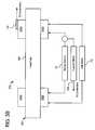
- FIG. 3Ais a schematic illustration of a conductivity cell and electrical schematic used for example with the renal failure therapy system of FIG. 1 .
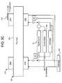
- FIGS. 3B and 3Care schematic views of alternative electrical systems which protect against and detect poor electrical connection between sensing electrodes and the dialysis instrument.
- FIGS. 4 and 5are perspective views of a tubing based conductivity cell using metal electrodes.
- FIG. 6is a perspective view illustrating one embodiment of a stand-alone hardware unit configured to hold the tubing based conductivity cell of FIGS. 3A , 3 B, 3 C and 4 for proper operation.
- FIG. 7is a graph illustrating a relationship between conductivity and a volume fraction of bicarbonate buffer in an buffer/glucose dialysate solution.
- FIG. 8is a graph showing cell calibration with conductivity standards.
- FIG. 9is a graph showing measured conductivity versus frequency.
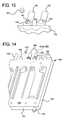
- FIGS. 10 and 11are perspective views of a tubing based conductivity cell using conductive plastic electrodes.
- FIG. 12is a side elevation view of a disposable cassette having an integrated conductivity cell.
- FIG. 13is a side-sectioned view of one embodiment for a disposable conductive contact.
- FIGS. 14 and 15are perspective views showing an embodiment for placing the disposable conductive contact of FIG. 13 in position for a needle/catheter access disconnection or valve leak detection.
- FIG. 16is a cutaway perspective view showing an embodiment for placing the disposable conductive contact of FIG. 13 in communication with fluid flowing through a tube or conduit.
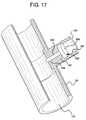
- FIG. 17is a perspective view of another embodiment for a disposable conductive contact.
- System 10is applicable generally to include any type of renal failure therapy system, such as peritoneal dialysis (“PD”), hemodialysis (“HD”), hemofiltration (“HF”), hemodiafiltration (“HDF”), colorectal dialysis and continuous renal replacement therapy (“CRRT”).
- PDperitoneal dialysis
- HDhemodialysis
- HFhemofiltration
- HDFhemodiafiltration
- CRRTcolorectal dialysis
- CRRTcontinuous renal replacement therapy
- System 10 in the illustrated embodimentincludes a dialysis instrument 12 .
- Dialysis instrument 12is configured for whichever type of renal failure therapy system is used.
- Dialysis instrument 12 as seen in FIG. 3Aincludes a central processing unit (“CPU”) 14 and a plurality of controllers 16 operable with central processing unit 14 .
- Central processing unit 14also operates with a graphical user-machine interface (“GUI”) 18 , e.g., via a video controller 16 , which includes a video monitor 20 and one or more type of input device 22 , such as a touch screen or electromechanical input device (e.g., membrane switch see also FIG. 1 ).
- GUIgraphical user-machine interface
- Disposable apparatus 30can include any one or more of supply bags 32 a to 32 c (referred to herein collectively as supply bags 32 or individually, generally as supply bag 32 ) shown here as dual or multi-chamber supply bags separating two fluids via a peel or frangible seal 34 , drain bag (not illustrated), a warmer bag 36 , bag tubes 38 a to 38 d (referred to herein collectively as tubing or tubes 38 or individually, generally as tube 38 ) and a disposable pumping/valve cassette 50 ( FIG. 2 ).
- supply bags 32 a to 32 creferred to herein collectively as supply bags 32 or individually, generally as supply bag 32
- drain bagnot illustrated
- bag tubes 38 a to 38 dreferred to herein collectively as tubing or tubes 38 or individually, generally as tube 38
- a disposable pumping/valve cassette 50FIG. 2
- any systemcan pump spent fluid to a house drain, such as a toilet or sink, instead of to drain bag.
- System 10can also include an inline heater, in
- Supply bags 32are shown having multiple chambers 42 a and 42 b , separated by frangible seal 34 , which hold different solutions depending on the type of therapy employed.
- chambers 42 a and 42 bcan hold buffer and glucose for PD or acetate and bicarbonate solution for HD.
- Supply bags 32are alternatively single chamber bags, which hold a single solution, such as lactate or acetate.
- multiple chamber bags with more than two chambersmay be employed to deliver parenteral nutrition solutions for example.
- cassette 50connects to supply bags 32 , drain bag and warmer bag 36 via tubes 38 a , 38 b and 38 c , respectively.
- Tube 38 druns to a patient connection 44 .
- suitable places to place the conductivity cells of system 10include different areas of tubing 38 , e.g., in each of supply tubes 38 a , in warmer bag tube 38 c or patient tube 38 d (could be two patient tubes, e.g., arterial and venous line, for hemodialysis).
- a conductivity cellcan also be placed in cassette 50 as seen in FIGS. 12 to 15 .
- One primary reason for the conductivity cells described hereinis to make sure that system 10 is delivering a proper solution or properly mixed solution to the patient, which in such case would make placing a conductivity cell in drain line 38 b unlikely. However, an additional conductivity cell could be placed in drain line 38 b , e.g., for diagnostic or therapy effectiveness purposes.
- Placing the conductivity cell in solution lines 38 aenables each supply bag 32 to be tested individually. Placing the conductivity cell in warmer bag tube 38 c or patient tube 38 d allows a single conductivity cell to ensure that proper fluid or properly mixed fluid is delivered to the patient. Likewise, placing the conductivity cell in the disposable cassette 50 enables a single conductivity cell to be used. Placement in cassette 50 has the added benefit that the cassette is already placed into operable contact with dialysis instrument 12 for operation. Placing the conductivity cell in tubing 38 in one embodiment requires that section of the tubing to be coupled operably to dialysis instrument 12 . It is contemplated however to provide a separate instrument or hardware device (see, e.g., hardware unit 112 of FIG. 6 ), which operates with a conductivity cell located in one of tubes 38 .
- an electrical scheme 70 for a conductivity cell 100(and other functions) is illustrated.
- the circuitry and processing for the electrical schematic 70 in one embodimentis placed on a printed circuit board (“PCB”), e.g., on one of controllers 16 or CPU 14 .
- the electronicsincludes a voltage or current source 72 , which for example is placed on safety controller 16 .
- Source 72generates an electrical signal, which travels along lead or trace 74 a , to one electrode 102 a of cell 100 , through a hydraulic or liquid pathway 104 of cell 100 , through a return electrode 102 b , return lead or trace 74 b , returning to source 72 .
- Frequency of the generated electrical signalis maintained at a desired level as seen below in connection with FIG. 9 .
- Liquid pathway 104interacts with a plurality of sensors, such as an electrical, e.g., voltage or resistance sensor 108 and/or a temperature sensor 110 .
- Electrical or resistance sensor 108can be a current or voltage sensor, which in combination with a known driving voltage or current, respectively, allows for a calculation of resistance and conductivity. Resistance sensor 108 is used in a conductivity calculation as described in detail below.
- Temperature sensor 110can be of a type such as a diode, thermistor, integrated circuit sensor, infrared sensor, or resistance temperature device (“RTD”).
- Electrical sensor 108can also be used to detect a patient access disconnection.
- ADSaccess disconnection system
- One suitable access disconnection system(“ADS”) is disclosed in copending patent application entitled, “Enhanced Signal Detection For Access Disconnection Systems”, filed Feb. 16, 2007, Ser. No. 11/676,110, assigned to the eventual assignee of the present disclosure (“The '110 application”).
- the referenced applicationdiscloses at least one embodiment that looks for a change in impedance occurring in the dialysate path. Hydraulic or liquid pathway 104 can thus be part of the dialysate path.
- the referenced applicationalso discloses at least one embodiment that looks for a change in impedance occurring in a blood path. Hydraulic or liquid circuit 104 can also therefore be part of the blood path.
- Temperature sensor 110senses a temperature of the medical fluid, e.g., dialysate, and takes advantage of the invasive metal electrodes 102 a and 102 b (referred to herein collectively as electrodes 102 or individually, generally as electrode 102 ). Knowing the temperature of the fluid is useful for fluid heating, patient safety, and perhaps pumping accuracy, e.g., for a volumetric system based on Boyle's Law. As seen, electrodes 102 can be multifunctional, which is true in any of the embodiments or configurations described below.
- the signals from sensors 108 and 110can be sent through a series of components (not illustrated), e.g., located on one of the controllers 16 , such as: (i) a filter or filters, which can act to filter noise from the signal, e.g., noise derived from the rotation from a blood pump to minimize a false negative and/or positive detection of needle dislodgment; (ii) a rectifier; (iii) a peak detector; and/or (iv) an analog to digital converter (“ADC”) to digitize the signal.
- Controller 16(referring to one of the controllers of FIG. 3 ) or CPU 14 includes a memory that stores the digital signal, e.g., in a buffer, for processing by a processor, such as a digital signal processor (“DSP”), which can be located at controller 16 or CPU 14 .
- DSPdigital signal processor
- Controller 16 or CPU 14continuously measures the electrical, e.g., voltage signal and processes the signal over time.
- the processorin one embodiment compares the digitized signals to look for changes over time and/or to compare the signals with a baseline or set point.
- ADSfor example, signals are compared to an expected or baseline signal.
- Controller 16 or CPU 14continually performs a calculation to determine whether a difference in the sensed signal compared to an expected or baseline signal is large enough to constitute a needle dislodgement. Variations in treatment can cause the expected or baseline signal to drift. System 10 can account for this.
- the signals in one embodimentare compared to an absolute norm, e.g., a range of values stored in a database or lookup table in the memory of controller 16 or CPU 14 . If the conductivity falls within a safe range of conductivities, the dialysate is assumed to be mixed properly. Otherwise an alarm condition is reached as discussed below.
- an absolute norme.g., a range of values stored in a database or lookup table in the memory of controller 16 or CPU 14 .
- safety controller 16receiving the signals from sensors 108 and 110 sends an error message to CPU 14 , which in turn sends a command to an instrument controller 16 to cause instrument 12 to take one or more evasive action, such as to shut down a pump, occlude a line 38 or close a valve (and corresponding fluid pathway) of cassette 50 .
- CPU 14in one embodiment also sends a command to GUI controller 16 .
- GUI controllercauses GUI 18 to display a message, such as an error and/or instructional message, on video monitor 20 .
- instrument 12can be equipped with speakers and sound or voice activation to sound an alarm or verbalize an alarm and/or corrective action.
- the visual or audible alarmalerts the patient, a medical care provider (e.g., doctor or registered nurse) or a non-medical care provider (e.g., family member or friend) of the conductivity error or needle dislodgment.
- a medical care providere.g., doctor or registered nurse
- non-medical care providere.g., family member or friend
- the alarm functionis particularly useful during dialysis therapy in a non-medical facility, such as in a home setting or self-care setting in which dialysis therapy is administered typically by the patient and/or a non-medical care provider in a non-medical setting or environment.
- the ADSalarms the patient or caregiver to ensure that the dialysis therapy has been terminated by, for example, checking that the blood pump has been automatically shut off to minimize blood loss to the patient.
- the alarmcan alert the patient or caregiver to check that peel seals 34 of dual chamber bags 32 have been opened.
- Instrument 12 of system 10halts pumping and/or occludes one or more appropriate tubes 38 or fluid paths of cassette 50 and also causes any improperly mixed fluid to be dumped to drain. Once fluid of the correct conductivity is sensed, treatment can continue.
- the alarmcan tell the hospital nurse or machine operator to check that the correct solution or solution having the correct dose of a medicament has been connected to the instrument 12 .
- the communication between electrical scheme 70 and instrument 12can be either hard-wired, for example if electrical scheme 70 is provided with instrument 12 .
- the communicationis a wireless communication (e.g., wireless RF interface).
- the separate unitcan communicate wirelessly with instrument 12 .
- the separate unitcan implement scheme 70 and have its own controller with memory, processing, power supply, etc., mentioned above.
- the unitcan include a transceiver for two-way communication with a transceiver located within instrument 12 .
- system 70uses an electrical signal, e.g., current, between spaced-apart electrodes 102 a and 102 b to test the quality of a medical fluid to be delivered to a patient, e.g., in a renal failure therapy setting or drug infusion setting. Electrodes 102 are disposed within the flow path 104 of the medical fluid so as to contact the medical fluid.
- an electrical signale.g., current
- FIGS. 3B and 3Cillustrate alternative electrical systems 170 and 270 , respectively.
- Systems 170 and 270include CPU 14 , controllers 16 , GUI 18 , monitor 20 and input devices 22 as shown and described above with system 70 of FIG. 3A . Accordingly these apparatuses are not shown in these additional figures.
- the primary difference with systems 170 and 270 versus system 70involves the addition of redundant contacts and sensing, which ensure proper performance regardless of or provides a detection of a faulty or improperly made electrical contact between at least electrodes 102 and the instrument or machine 12 .
- Systems 170 and 270mitigate a contact failure mode that may not be detectable with system 70 .
- System 170shows dual contacts on each electrode 102 a and 102 b that compensate for a poor electrical connection between the instrument 12 ( FIGS. 1 and 2 ) and either electrode 102 .
- system 170includes a signal source 72 applying a known signal, e.g., voltage signal, to contacts 102 a and 102 b .
- Sensor 108is shown here as a current meter, which measures the current flowing from signal source 72 to conductivity cell 100 .
- the secondary contact at each electrode 102 a and 102 bcommunicates with a voltage meter 172 , which measures the actual voltage applied to the electrodes 102 .
- the ratio of the measured current to measured voltage, and other system constants,are used to determine the conductivity of the fluid between the electrodes.
- All of the current measured through electrodes 102 supplied from signal source 72must be applied through the fluid because there is no other path that the current can take between the electrodes. If there is a relatively poor electrical contact between the signal source and the electrode, however, the voltage applied to electrodes 102 decreases, while the current supplied through electrodes 102 remains within normal specifications. If voltage meter 172 measures a voltage at the electrodes 102 that is outside a normal operating voltage due to an inadequate electrical contact between signal source 72 and electrodes 102 , the electronics within instrument 12 detects the voltage as being out of specification and signals a faulty cassette or cell loading alarm. Instrument 12 can confirm such condition by detecting a large difference between the voltage that signal source 72 applies versus the voltage that voltage meter 172 measures.
- System 270shows another alternative embodiment in FIG. 3C .
- System 270includes signal source 72 , current meter 108 (for conductivity determination) and voltage meter 172 discussed above with system 170 .
- System 270additionally measures a contact resistance between conductivity cell 100 and instrument 12 .
- Switches S 1 and S 2connect an ohmmeter 272 to electrodes 102 a and 102 b , respectively, for example in a multiplexed fashion at the beginning of therapy to interrogate the electrical connection at each electrode 102 a and 102 b separately.
- Ohmmeter 272measures a total resistance between electrodes 102 and the electronic circuits contained within instrument 12 . After the resistance is determined to be within an allowable tolerance, switches S 1 and S 2 connect the electrodes 102 to signal source 72 and voltage meter 172 . It should be noted that system 270 can connect signal source 72 and voltage meter 172 to each other within instrument 12 so that the signal source and voltage meter do not need to be connected separately at electrodes 102 as shown in FIG. 3C .
- cell 100 aillustrates one suitable flow-through conductivity cell.
- the electrodes of cell 100 acan be used alternatively or additionally for any of the types of sensing discussed herein, e.g., needle/catheter access disconnection, valve leak detection, and temperature sensing.
- the tube or conduit of cell 100 ais labeled conduit 38 , 50 , which signifies that cell 100 a can be part of different fluid flow structures, such as cassette 50 , one of tubes 38 as discussed above, a supply bag 32 or other container, a tube of an infusion pump or any type of relatively non-conductive fluid conduit, be it disposable or non-disposable.
- Cell 100 acan interface directly with instrument 12 or with a separate hardware unit 112 shown in FIG. 6 .
- Cell 100 atransmits a current through a medical fluid, e.g., dialysate, flowing within conduit 38 , 50 between a pair of opposing electrodes 102 a and 102 b .
- Instrument 12 or separate hardware unit 112includes circuitry 70 shown in FIG. 3A , which controls the transmission of the electrical current between the electrodes 102 and measures the resistance of the medical fluid.
- conduit 38 , 50is injection molded plastic.
- conduit 38 , 50is injection molded around and sealed to electrodes 102 .
- conduit 38 , 50is extruded plastic.
- electrodes 102are bonded adhesively to conduit 38 , 50 .
- electrodes 102are inserted into conduit 38 , 50 via an insert molding process.
- Conduit 38 , 50can accordingly be made of moldable material, which is chemically and biologically inert with respect to the medical fluids, e.g., dialysate or drugs, and is electrically insulative in an embodiment.
- Suitable materials for conduit 38 , 50include acrylonitrile butadiene styrene (“ABS”), polyvinyl chloride (“PVC”), silicone rubber, polyolefin, cyclic olefin and cyclic olefin copolymers (“COC”), polycarbonates, synthetic and natural rubber, thermoplastic elastomers, glass, silicone and other semiconductors used in micro electro-mechanical (“MEMS”) fabrication processes.
- ABSacrylonitrile butadiene styrene
- PVCpolyvinyl chloride
- COCcyclic olefin copolymers
- polycarbonatessynthetic and natural rubber
- thermoplastic elastomersglass, silicone and other semiconductors used in micro electro-mechanical (“MEMS”) fabrication processes.
- Electrodes 102are stainless steel in one embodiment, which is generally considered as a safe metal for contacting a medical fluid. Electrodes 102 a and 102 b can alternatively be formed of different materials, perhaps for better electrical or thermal properties, so to provide a thermocouple effect for measuring the temperature of the medical fluid, and/or in a non-sterile situation or for example, sensing effluent or spent fluid (that has already contacted the patient) electrodes can alternatively be made of a conductive plastic described in more detail below. Suitable conductive plastics are described in the '110 application referenced and incorporated above.
- Electrodes 102 a and 102 b of cell 100 aare illustrated as being cylindrical but could alternatively be square, rectangular or of an arbitrary cross-section. Electrodes 102 extend into or through fluid pathway 104 in an at least substantially perpendicular orientation relative to the flow axis through the pathway. Alternatively, electrodes may extend along the fluid pathway, e.g., as surface-printed electrodes (discussed below) having a controlled separation distance. It is important to know the amount of surface area of electrodes 102 that the medical fluid contacts accurately so that the conductivity can be calculated accurately.
- conduit 38 , 50includes or provides pockets 114 a and 114 b (referred to herein collectively as pockets 114 or generally, individually as pocket 114 ) that receive electrodes 102 a and 102 b , respectively.
- Conduit 38 , 50also includes or provides posts 116 a and 116 b (referred to herein collectively as posts 116 or generally, individually as post 116 ), which hold electrodes 102 a and 102 b , respectively, firmly and in the proper at least substantially perpendicular orientation with respect to the flow of medical fluid through pathway 104 .
- Extensions 116also provide additional contact area for electrodes 102 to be sealed within conduit 38 , 50 of cell 100 a.
- electrodes 102can be adhesively joined to cell 100 a .
- the adhesivecan be applied within posts 116 , such that an adequate amount of adhesive is applied, but wherein the adhesive is kept safely away from fluid pathway 104 .
- the plastic to metal adhesive processis readily amenable to high-volume production.
- the processcan include forming molded, e.g., insert molded posts 116 , inserting, e.g., stainless steel, electrodes or cannula needles 102 , applying a metered adhesive (e.g., LoctiteTM adhesive) and cross-linking the adhesive and material of plastic post 116 (e.g., ABS) for example with ultraviolet (“UV”) light.
- a metered adhesivee.g., LoctiteTM adhesive
- plastic post 116e.g., ABS
- UVultraviolet
- Parameters needing to be tightly controlled during high-volume manufacturinginclude fluid path length L, electrode size and surface characteristics, and hydraulic area A h .
- An alternating current (“AC”) signalas either a driving current (i) or driving voltage (V), is used in one embodiment to preclude anodic loss of the electrodes.
- a direct currentis not ideal because it would result in anodic erosion of one electrode, altered sensor calibration and create contaminates in the medical fluid. Resistance as has been discussed is determined by controlling the driving current (i) or voltage (V), measuring the other and calculating resistance.
- cell constant k for full contact electrodes 102 of FIG. 3Ais unity.
- the electrode to solution contact areacan be expressed as: A e ⁇ *D h *D e
- the cell constant k for cell 100 ais then derived using the value of A e and hydraulic area A h diameter Db of electrode 102 of cell 100 a .
- Controlling L′/Lensures measurement accuracy and minimizes uncertainty without requiring overly stringent manufacturing controls of cross-sectional flow path area or electrode area.
- the electrode variancemay be minimized by making the electrode surface area, A e , larger than the hydraulic area, A h .
- circuitry 70 and cell 100 ahave a sensitivity of about 10 ohms or less when expecting to see a mixture of about 10,000 ohm resistance.
- a conductivity of about 12.3 mS/cmthis corresponds to a sensitivity of about 0.01 mS/cm.
- FIG. 7shows a linear relationship of conductivity with varying volume fraction of bicarbonate buffer in a dialysis solution.
- conductivityis a function of mix ratio.
- f Bincreases, so does conductivity.
- Diamonds in FIG. 7represent 1.36 percent glucose dialysate.
- Squares in FIG. 7represent 3.86 percent glucose dialysate.
- FIG. 7shows a linear relationship of conductivity with varying volume fraction of bicarbonate buffer in a dialysis solution.
- conductivityis a function of mix ratio.
- Diamonds in FIG. 7represent 1.36 percent glucose dialysate.
- Squares in FIG. 7represent 3.86 percent glucose dialysate.
- Modulating frequencyprovides an alternative method for distinguishing solution mix concentration.
- FIG. 9illustrates the dependence of resistance (more generally impedance) or conductivity on signal frequency. As seen, the resistances are more distinct at lower signal frequencies (glucose concentrate in triangles, bicarbonate concentrate in diamonds and mixed solution in squares). When a certain signal frequency is reached, measured resistances begin to decrease. Therefore, in one embodiment signal frequency is maintained at a suitably low level, such as between about 10 to 100,000 Hz, e.g., at about 1000 Hz and solutions may be distinguished as differences in resistance measured. Alternatively, solutions may be distinguished by the frequency at which the resistance decreases, e.g., about 10,000 Hz for the glucose concentrate, about 100,000 Hz for the mixed solution and about 500,000 Hz for the buffer solution.
- a processore.g., located at CPU 14 or controller 16 ) applies an algorithm to the measured resistance, which compensates for temperature to calculate the conductivity of the medical fluid.
- the processorperforms a matching check to compare the calculated conductivity of the medical fluid with, e.g., a look-up table in a database for the particular pharmaceutical substance to determine if the concentration of the pharmaceutical substance within the medical fluid is within an acceptable range.
- Detectable conditions for dialysisinclude, for example: (i) no disposable cell loaded (alarm); (ii) disposable cell loaded (no alarm); (iii) only glucose concentration detected (alarm); (iv) only bicarbonate concentration detected (alarm); and (v) mixed solution detected (no alarm).
- the processorIf the measured concentration of the pharmaceutical substance is outside an acceptable range, the processor outputs a signal (e.g., from safety controller 16 to CPU 14 of the dialysis, infusion or other medication delivery system 10 ) to provide an alarm to the user and/or prevent the medication delivery system from delivering the medical fluid (e.g., by shutting down a pump, tube 38 or pathway of cassette 50 ). If the measured concentration of the pharmaceutical substance is within an acceptable range, the processor outputs a signal to proceed with the delivery of the medical fluid. In the case of APD, fluid mixing quality can be tested once (for each bag 32 ) before the start of therapy or during therapy to ensure proper mixing. Other detectable fluids include but are not limited to a parenteral compounding fluid, an intravenous infusion fluid and a chemotherapeutic compounding fluid.
- detectionis performed on a relative rather than an absolute basis.
- cell 100looks for a step change or relative change in conductivity.
- a lookup table or absolute comparisonis not needed.
- One example of this embodimentis possible in connection with dual chamber bag 32 having chambers 42 a and 42 b separated by a frangible seal 34 .
- Dual chamber bags 32 in the illustrated embodimenthave integral tubing/connectors 46 in communication with chambers 42 b . While tubing 46 is shown as being a relatively short run in FIG. 1 , integral tubing 46 can alternatively be longer and in one embodiment extend all the way to and connect directly to cassette 50 . Tubing/connectors 46 are filled initially with solution concentrate from chamber 42 b .
- Electrodes 102 positioned here along each of tubes 46will therefore initially sense pure (or near pure) solution of chamber 42 b flowing from bag 32 , after which properly mixed fluid flows past electrodes 102 and causes a characteristic step change in conductivity. If solutions from chambers 42 a and 42 b are not mixed properly, the expected step change in conductivity does not occur, indicating that the chambers have not been mixed. This relative approach is advantageous in one respect because it does not necessitate an absolute calibration and use of a lookup table.
- hardware unit 112illustrates an embodiment of a separate testing mechanism or hardware unit including circuitry 70 which is, configured to apply an electrical signal and to measure the resistance of a medical fluid through a cell such as cell 100 a . While separate hardware unit 112 is shown in operation with cell 100 a , it should be appreciated that the hardware unit is alternatively operable with any of the cells discussed herein. Hardware unit 112 maintains the cell in a secured position and includes leads or contacts that contact each of the electrodes 102 of the cell to enable the cell to communicate electrically with the rest of circuit 70 . A snap-fit is provided in one embodiment to provide enough force to minimize contact resistance but still allow the cell to be loaded and unloaded in an efficient and ergonomic manner. Hardware unit 112 can include a processor and hard-wired or wireless communication equipment as discussed herein.
- cell 100 billustrates another embodiment for a conductivity, ADS, leak detection and/or heat sensor.
- Cell 100 bagain includes a pair of electrodes 102 a and 102 b , which in one embodiment are overmolded around a section of conduit 38 , 50 defining hydraulic pathway 104 of hydraulic diameter D h , having hydraulic Area A h and length L as described above.
- cell 100 bis formed using various sections of conduit 38 , 50 , which are inserted into a mold such that adjacent ends of the conduits are spaced apart. Then, an electrically conductive material, such as an electrically conductive plastic referenced above, is overmolded around adjacent ends of the conduit 38 , 50 .
- the space between the adjacent ends of the tubes 104is filled with the conductive material, such that the conductive plastic forms a portion of the surface of the fluid passageway 104 of the cell 100 b as seen best in FIG. 11 .
- the exposed portions of the conductive material within the passageway 104form the electrodes 102 that are in fluid communication with the medical fluid that flows through the passageway 104 .
- exposed portions of conductive electrodes 102can include inwardly facing surface area increasing apparatuses or members. In any case, the overmolding process connects adjacent tubes and provides a seal therebetween to form a continuous passageway 104 .
- conductive polymer electrodes 102are press-fit into conduit 38 , 50 .
- conductive polymer electrodes 102are solvent bonded and UV cured and cross-linked to conduit 38 , 50 .
- electrodesare printed or deposited on the inner surface of conduit 38 , 50 , e.g., via a conductive ink in a screening or photolithographic process.
- the inkcan be applied in such a manner to a flexible membrane of disposable cassette 50 or other disposable plastic component of a medication delivery system.
- Cassette 50generally models a Homechoice® APD system cassette marketed by the eventual assignee of the present disclosure.
- Cassette 50in general includes a rigid structure having rigid outer walls 52 a to 52 d (referred to herein collectively as walls 52 or generally, individually as wall 52 ), rigid inner walls 54 (defining inner pump chambers P 1 and P 2 and inner fluid pathways such as pathway 104 ), rigid fluid ports 56 (connectable sealingly to tubing 38 ) and a pair of flexible membranes 58 sealed to outer rigid walls 52 and inner rigid walls 54 .
- Suitable materials for the rigid portion of cassette 50include medical grade engineered thermoplastics, e.g., polycarbonate, acrylic, cyclic olefins and their copolymers, thermoplastic elastomers, and their blends and alloys.
- Suitable materials for flexible membrane 58include polyvinyl chloride, olefin, coextruded multi-layer films and micro-layer coextruded films (e.g., 10 to 1000 layers typically). It should be appreciated that the Homechoice® APD system cassette serves merely as an example and that other fluid pumping/valving cassette made of different materials can employ cells 100 c and 100 d.
- Cell 100 cis similar to cell 100 a in that it employs cylindrical electrodes 102 a and 102 b that extend all the way across fluid pathway 104 and penetrate through slightly into inner wall 54 a for the process control and accuracy reasons discussed above in connection with cell 100 a .
- Upper, outer wall 52 acan be molded sealingly around electrodes 102 or electrodes 102 can be sealed adhesively to upper, outer wall 52 a of cassette 50 . Press-fitting or other types of mechanical bonding can be used additionally or alternatively.
- Upper wall 52 ccan include or define ports or extensions 60 a and 60 b that provide additional surface area for cassette 50 to be sealed and crosslinked to the adhesive to seal to electrodes 102 .
- FIGS. 2 and 12illustrate an alternative cassette-based electrical cell arrangement 100 d .
- Cell 100 demploys a layer of conductive ink stencil printed, screen printed or applied via a photolithographic process in a continuous manner onto inner and outer surfaces of flexible membrane 58 to form electrodes 102 a and 102 b .
- Suitable conductive inksare provided for example by carbon, conductive polymers, metalized inks, metal particle filled polymers, and nanoparticle filled conductive inks.
- electrodes 102 a and 102 b of cell 100 dare separated by a hydraulic path length L.
- the contact area A e of electrodes 102 of cell 100 dis the length l that the inked electrodes extend downwardly on the inner surface of membrane 58 multiplied by the width w of electrodes 102 on the inner surface of the membrane as seen in FIG. 12 .
- the inked electrodes 102 of cell 100 dare applied thinly enough that a standard flexible plastic membrane to rigid plastic piece bonding procedure, such as a heat seal, ultrasonic seal, solvent or adhesive bond is sufficient to seal the electrode areas of membrane 58 to upper, rigid plastic wall 52 a . It may be necessary however to apply a local application of a sealant to the electrode areas to ensure a proper seal.
- the inked electrodes 102 of cell 100 dare applied in a sufficient length l and width w to provide a sufficient amount conductive mass to carry the signal of source 72 , which can be on the order of micro- or milli-Watts.
- electrodes 102 of cell 100 c and cell 100 dcan be placed in any suitable position, on any suitable wall 52 or membrane of cassette 50 .
- Electrode 202 of FIG. 13is advantageous from a number of respects including, size, ease of manufacture and ease of installation with a fluid conduit, e.g., in communication with one of tubes 38 ( FIG. 1 ) or fluid cassette 50 .
- a fluid conduite.g., in communication with one of tubes 38 ( FIG. 1 ) or fluid cassette 50 .
- electrode 202 of FIG. 13is shown as being inserted into one of the walls 52 or 54 of cassette 50 .
- Electrode 202includes a fluid contact interface 204 extending to an annular sidewall 206 , which extends upwardly to a retainer ring portion 208 of the electrode.
- Retainer 208is bent and configured so as to be somewhat pliable and capable of being press-fit or frictionally engaged with a stepped or tapered aperture 68 formed in wall 52 and 54 of cassette 50 .
- Stepped or tapered aperture 68can provide or define an annular receiving groove 76 , which is sized and shaped to snap-fittingly receive the upper edge 210 of retainer ring portion 208 of electrode 202 .
- Electrode 202it may be that the apparatus and mechanical installation procedure of electrode 202 just described is enough to prevent (i) medical fluid or dialysate from escaping through the interface between retainer ring portion 208 and stepped aperture 66 of cassette 50 and (ii) air from outside cassette 50 from reaching sterile fluid in hydraulic pathway 104 without an additional sealing apparatus.
- a sterile sealing barrier 212e.g., of an o-ring nature, is provided to prevent fluid or air from leaking out of or into, respectively, cassette 50 .
- a suitably bondable adhesive or overmolding procedure discussed abovecan be employed.
- Sealing ring 212is made of a suitable medical grade compressible material, such as silicon, thermoplastic elastomer or isoprene.
- Flange portion 214 of electrode 202compresses sealing ring 212 against stepped surface 78 of stepped or tapered aperture 68 . It is also possible that sidewall 206 of electrode 202 can press sealing ring 212 outwardly against side surface 80 of stepped or tapered aperture 68 .
- Electrode 202is made of stainless steel in one embodiment, e.g., for contacting fresh, sterile dialysate or other medicament. It is contemplated however to make electrode 202 and any of electrodes 102 described above from a different conductive material, such as a conductive polymer. Further, different metals could be used, such as copper or aluminum, for electrical or thermal sampling of a waste fluid, for example, such as fluid delivered from cassette 50 , through drain line 38 b to drain as shown in FIG. 1 .
- contact 202will have a contact area A e , which is generally defined by the diameter D e of contact portion 204 . Fluid flows through pathway 104 and contacts portion 204 . Electrode 202 (e.g., pair of electrodes 202 ) is in turn connected electrically via a contact 74 (referring generally to one of contacts 74 a and 74 b ), directly or indirectly, to signal source 72 located within instrument 12 . Alternatively, the pair of electrodes interfaces with a stand-alone hardware unit, such as cell holder 112 of FIG. 6 .
- any of electrodes 102 or electrodes 202for multiple purposes, such as for a needle or catheter access disconnection system (“ADS”), temperature sensing, valve leak detection in addition to conductivity measurement.
- ADSneedle or catheter access disconnection system
- temperature sensinge.g., temperature sensing
- valve leak detectione.g., valve leak detection in addition to conductivity measurement.
- a pair of electrodes 102 or 202can be used to detect conductivity at the beginning of each bagged dialysis cycle (e.g. peritoneal dialysis or bagged hemodialysis solution) to ensure that the dialysate through a hydraulic pathway 104 (e.g., from dual chamber bags 32 ) has been mixed properly.
- contacts 202can then be used to sense an impedance of the dialysate through hydraulic pathway 104 as disclosed in the '110 application referenced above for ADS purposes.
- Conductivity sensing and ADS sensing in one embodimentboth require that at least one signal be injected through electrodes 202 to the dialysate.
- the same signal source 72may be used, however, a different and/or additional signal source could be provided.
- the different sensingrequires different signal processing, e.g., software.
- a separate dedicated pair of electrodes 202can be provided, e.g., at the to- and from-heater bag ports 56 for temperature sensing and heater control.
- the temperature sensing and heating sensing systemcould use a single electrode 202 at, e.g., from-heater port 56 .
- the Homechoice® APD system and associated disposable cassette illustrated throughout this applicationuses a batch heating system via a warmer bag 36 shown in FIG. 1 .
- Electrodes 102 and 202can be used alternatively with an in-line heating system, for example by placing electrodes 102 and 202 upstream and downstream of an in-line fluid heating pathway.
- alternative cassette 150includes rigid sidewalls 152 having or providing a plurality of fluid ports 156 and a top wall 154 defining or including various apertures and fluid pathways.
- Two of ports 156 shown in FIG. 14are shown in Detail XV in FIG. 15 as including bulkheads 158 .
- Bulkheads 158include or define stepped or tapered electrode receiving apertures 68 , described above, which receive electrodes 202 .
- Ports 156 having bulkhead 158 receiving electrodes 202can be, for example, to- and from-patient ports 156 , at which system 10 tests for an access disconnection.
- the bulkhead ports 156are any that are any downstream of one or more valve seat of cassette 150 , wherein system 10 uses those electrodes 202 to determine if any valve seat or corresponding valve actuator is not functioning properly.
- bulkhead ports 156can be supply ports upstream of the cassette valves for conductivity sensing, wherein the valves can virtually immediately be closed to stop flow of improperly mixed fluid through cassette 156 (or improper dose or type of drug in a drug infusion machine) when such a situation is sensed.
- tube or conduitdefines or includes an alternative aperture 168 , which has an at least substantially uniform inner diameter.
- tube or conduit 38includes or defines tapered aperture 68 .
- Electrode 202is press-fit, overmolded into and/or solvent bonded to aperture 168 as has been described herein.
- Electrode 202 in conduit 38can be used alone or in a pair of electrodes 202 for any one or more of the functions described herein. Electrode 202 is made of any of the materials discussed herein.
- Electrode 202is different than that of FIG. 13 .
- electrode 202includes a fluid contact interface 204 , an annular sidewall 206 and a flange portion 214 .
- retention ring portion 208 discussed aboveis not provided.
- flange portion 214is sized to be slightly wider than the inner diameter of aperture 168 .
- Aperture 168can define a groove, similar to groove 76 of FIG. 13 , into which the outer edge of flange portion 214 snap-fits for permanent or semi-permanent installation into tube or conduit 35 .
- Tube or conduit 38can be formed integrally with an elongated section of tubing or conduit.
- tube or conduit 38 in FIG. 16is configured to seal, semi-permanently or permanently with one or more section of elongated tubing or conduit.
- electrode 302illustrates a further alternative electrode configuration.
- tube 38is formed with or connected to a T-extension 138 .
- T-extension 138defines an aperture 140 into which electrode 302 is placed.
- Electrode 302includes a stem 304 and a head 306 . Head 306 bottoms out against a seat 142 of T-extension 138 .
- Seat 142defines a cylindrical aperture 144 through which stem 304 of electrode 302 is inserted.
- a diameter of aperture 144is smaller than that of stem 304 , such that a compression seal is formed. Further sealing can be provided via overmolding and/or bonding as has been described herein.
- Electrode 302is used alternatively with a disposable cassette, such as cassette 50 or 150 . Electrode 302 can be any of the materials described herein and operate alone or in a pair (e.g., as a cell).
- instrument 12 or separate hardware unitcan interfere with electrodes 102 , 202 , 302 through physical contact, such as via a conductive pin, or can be non-physically coupled, e.g., through an infrared or other type of energy sensor.
- an infrared (“IR”) temperature sensorcan be pointed towards head 306 of electrode 302 to non-mechanically or non-physically sense a temperature of head 306 and fluid flowing past stem 304 of electrode 302 indirectly.
Landscapes
- Health & Medical Sciences (AREA)
- Heart & Thoracic Surgery (AREA)
- Life Sciences & Earth Sciences (AREA)
- Urology & Nephrology (AREA)
- Vascular Medicine (AREA)
- General Health & Medical Sciences (AREA)
- Public Health (AREA)
- Biomedical Technology (AREA)
- Hematology (AREA)
- Anesthesiology (AREA)
- Animal Behavior & Ethology (AREA)
- Engineering & Computer Science (AREA)
- Emergency Medicine (AREA)
- Veterinary Medicine (AREA)
- Chemical & Material Sciences (AREA)
- Cardiology (AREA)
- Chemical Kinetics & Catalysis (AREA)
- Electrochemistry (AREA)
- Physics & Mathematics (AREA)
- Analytical Chemistry (AREA)
- Biochemistry (AREA)
- General Physics & Mathematics (AREA)
- Immunology (AREA)
- Pathology (AREA)
- External Artificial Organs (AREA)
Abstract
Description
σ=(L*i)/(V*Ah),
which can be expressed in units of mS/cm. The geometry of
σ=(k*L*i)/(V*Ah),
Ae≈π*Dh*De
The cell constant k for
L′/L>>A′e/Ae, andL′/L>>A′h/Ah
Ae=π*l*De
Hydraulic area Ahof
Ah=l×w
where w is the width of cassette50 (see
Claims (21)
Priority Applications (6)
| Application Number | Priority Date | Filing Date | Title |
|---|---|---|---|
| US11/773,644US8287724B2 (en) | 2007-07-05 | 2007-07-05 | Dialysis fluid measurement systems using conductive contacts |
| PCT/US2008/064857WO2009009226A2 (en) | 2007-07-05 | 2008-05-27 | Dialysis fluid measurement systems using conductive contacts |
| JP2010514915AJP5450403B2 (en) | 2007-07-05 | 2008-05-27 | Dialysis fluid measurement system using conductive contact |
| EP08756291.4AEP2173403B1 (en) | 2007-07-05 | 2008-05-27 | Dialysis fluid measurement systems using conductive contacts |
| EP18186908.2AEP3421060B1 (en) | 2007-07-05 | 2008-05-27 | Dialysis fluid measurement systems using conductive contacts |
| JP2013266827AJP5684889B2 (en) | 2007-07-05 | 2013-12-25 | Dialysis fluid measurement system using conductive contact |
Applications Claiming Priority (1)
| Application Number | Priority Date | Filing Date | Title |
|---|---|---|---|
| US11/773,644US8287724B2 (en) | 2007-07-05 | 2007-07-05 | Dialysis fluid measurement systems using conductive contacts |
Publications (2)
| Publication Number | Publication Date |
|---|---|
| US20090012452A1 US20090012452A1 (en) | 2009-01-08 |
| US8287724B2true US8287724B2 (en) | 2012-10-16 |
Family
ID=39745668
Family Applications (1)
| Application Number | Title | Priority Date | Filing Date |
|---|---|---|---|
| US11/773,644Active2031-08-15US8287724B2 (en) | 2007-07-05 | 2007-07-05 | Dialysis fluid measurement systems using conductive contacts |
Country Status (4)
| Country | Link |
|---|---|
| US (1) | US8287724B2 (en) |
| EP (2) | EP2173403B1 (en) |
| JP (2) | JP5450403B2 (en) |
| WO (1) | WO2009009226A2 (en) |
Cited By (12)
| Publication number | Priority date | Publication date | Assignee | Title |
|---|---|---|---|---|
| WO2014201358A3 (en)* | 2013-06-14 | 2015-10-29 | Bayer Medical Care Inc. | Portable fluid delivery system |
| WO2016018671A1 (en)* | 2014-07-28 | 2016-02-04 | Haemonetics Corporation | System and method for detecting fluid type |
| US9839735B2 (en) | 2015-09-08 | 2017-12-12 | Fresenius Medical Care Holdings, Inc. | Voice interface for a dialysis machine |
| US9861733B2 (en) | 2012-03-23 | 2018-01-09 | Nxstage Medical Inc. | Peritoneal dialysis systems, devices, and methods |
| US9907897B2 (en) | 2011-03-23 | 2018-03-06 | Nxstage Medical, Inc. | Peritoneal dialysis systems, devices, and methods |
| US10507319B2 (en) | 2015-01-09 | 2019-12-17 | Bayer Healthcare Llc | Multiple fluid delivery system with multi-use disposable set and features thereof |
| US10549084B2 (en) | 2014-01-10 | 2020-02-04 | Bayer Healthcare Llc | Single-use disposable set connector |
| WO2021247582A1 (en)* | 2020-06-01 | 2021-12-09 | DASH Anesthesia | Intravenous fluid delivery system and apparatus |
| US11207454B2 (en) | 2018-02-28 | 2021-12-28 | Nxstage Medical, Inc. | Fluid preparation and treatment devices methods and systems |
| US11738152B2 (en) | 2016-06-15 | 2023-08-29 | Bayer Healthcare, Llc | Multi-use disposable system and syringe therefor |
| US11857497B2 (en) | 2022-03-08 | 2024-01-02 | Equashield Medical Ltd | Fluid transfer station in a robotic pharmaceutical preparation system |
| US12048791B2 (en) | 2017-06-24 | 2024-07-30 | Nxstage Medical, Inc. | Peritoneal dialysis fluid preparation and/or treatment devices methods and systems |
Families Citing this family (59)
| Publication number | Priority date | Publication date | Assignee | Title |
|---|---|---|---|---|
| US10537671B2 (en) | 2006-04-14 | 2020-01-21 | Deka Products Limited Partnership | Automated control mechanisms in a hemodialysis apparatus |
| US8273049B2 (en) | 2007-02-27 | 2012-09-25 | Deka Products Limited Partnership | Pumping cassette |
| US9717834B2 (en) | 2011-05-24 | 2017-08-01 | Deka Products Limited Partnership | Blood treatment systems and methods |
| US8366316B2 (en)* | 2006-04-14 | 2013-02-05 | Deka Products Limited Partnership | Sensor apparatus systems, devices and methods |
| US7794141B2 (en)* | 2006-04-14 | 2010-09-14 | Deka Products Limited Partnership | Thermal and coductivity sensing systems, devices and methods |
| US8425471B2 (en)* | 2007-02-27 | 2013-04-23 | Deka Products Limited Partnership | Reagent supply for a hemodialysis system |
| US8357298B2 (en) | 2007-02-27 | 2013-01-22 | Deka Products Limited Partnership | Hemodialysis systems and methods |
| US20090107335A1 (en) | 2007-02-27 | 2009-04-30 | Deka Products Limited Partnership | Air trap for a medical infusion device |
| KR102444304B1 (en) | 2007-02-27 | 2022-09-19 | 데카 프로덕츠 리미티드 파트너쉽 | hemodialysis system |
| US8409441B2 (en) | 2007-02-27 | 2013-04-02 | Deka Products Limited Partnership | Blood treatment systems and methods |
| US9028691B2 (en) | 2007-02-27 | 2015-05-12 | Deka Products Limited Partnership | Blood circuit assembly for a hemodialysis system |
| US8042563B2 (en) | 2007-02-27 | 2011-10-25 | Deka Products Limited Partnership | Cassette system integrated apparatus |
| US8393690B2 (en) | 2007-02-27 | 2013-03-12 | Deka Products Limited Partnership | Enclosure for a portable hemodialysis system |
| US8491184B2 (en) | 2007-02-27 | 2013-07-23 | Deka Products Limited Partnership | Sensor apparatus systems, devices and methods |
| US8562834B2 (en) | 2007-02-27 | 2013-10-22 | Deka Products Limited Partnership | Modular assembly for a portable hemodialysis system |
| US7736328B2 (en) | 2007-07-05 | 2010-06-15 | Baxter International Inc. | Dialysis system having supply container autoconnection |
| US8287724B2 (en) | 2007-07-05 | 2012-10-16 | Baxter International Inc. | Dialysis fluid measurement systems using conductive contacts |
| US20100056975A1 (en)* | 2008-08-27 | 2010-03-04 | Deka Products Limited Partnership | Blood line connector for a medical infusion device |
| US8771508B2 (en)* | 2008-08-27 | 2014-07-08 | Deka Products Limited Partnership | Dialyzer cartridge mounting arrangement for a hemodialysis system |
| WO2009049235A2 (en)* | 2007-10-12 | 2009-04-16 | Deka Products Limited Partnership | Systems, devices and methods for cardiopulmonary treatment and procedures |
| US8708950B2 (en) | 2010-07-07 | 2014-04-29 | Deka Products Limited Partnership | Medical treatment system and methods using a plurality of fluid lines |
| JP5595930B2 (en)* | 2008-01-23 | 2014-09-24 | デカ・プロダクツ・リミテッド・パートナーシップ | Disposable components for fluid line automatic connection systems |
| US9078971B2 (en) | 2008-01-23 | 2015-07-14 | Deka Products Limited Partnership | Medical treatment system and methods using a plurality of fluid lines |
| CN104841030B (en) | 2009-10-30 | 2017-10-31 | 德卡产品有限公司 | For the apparatus and method for the disconnection for detecting intravascular access device |
| US8753515B2 (en) | 2009-12-05 | 2014-06-17 | Home Dialysis Plus, Ltd. | Dialysis system with ultrafiltration control |
| DE102009060330A1 (en)* | 2009-12-23 | 2011-06-30 | Fresenius Medical Care Deutschland GmbH, 61352 | Dialysis machine, in particular peritoneal dialysis machine |
| US8501009B2 (en) | 2010-06-07 | 2013-08-06 | State Of Oregon Acting By And Through The State Board Of Higher Education On Behalf Of Oregon State University | Fluid purification system |
| US8525533B2 (en)* | 2010-09-16 | 2013-09-03 | Fresenius Medical Care Holdings, Inc. | Conductivity detector for fluids |
| EP3205362B1 (en) | 2011-05-24 | 2022-07-06 | DEKA Products Limited Partnership | Hemodialysis system |
| JP2014533133A (en)* | 2011-10-07 | 2014-12-11 | ホーム・ダイアリシス・プラス・リミテッドHome DialysisPlus, Ltd. | Purification of heat exchange fluids for dialysis systems |
| JP6027129B2 (en) | 2011-11-04 | 2016-11-16 | デカ・プロダクツ・リミテッド・パートナーシップ | Medical systems that use multiple fluid lines |
| WO2013185080A1 (en)* | 2012-06-08 | 2013-12-12 | Fresenius Medical Care Holdings, Inc. | System and method of monitoring and control of ultrafiltration volume during peritoneal dialysis using segmental bioimpedance |
| GB201305755D0 (en) | 2013-03-28 | 2013-05-15 | Quanta Fluid Solutions Ltd | Re-Use of a Hemodialysis Cartridge |
| GB201309561D0 (en)* | 2013-05-29 | 2013-07-10 | Quanta Fluid Solutions Ltd | Liquid conductivity measurement cell |
| GB201314512D0 (en) | 2013-08-14 | 2013-09-25 | Quanta Fluid Solutions Ltd | Dual Haemodialysis and Haemodiafiltration blood treatment device |
| EP3838308A1 (en) | 2014-04-29 | 2021-06-23 | Outset Medical, Inc. | Dialysis system and methods |
| GB201409796D0 (en) | 2014-06-02 | 2014-07-16 | Quanta Fluid Solutions Ltd | Method of heat sanitization of a haemodialysis water circuit using a calculated dose |
| JP6637035B2 (en)* | 2014-09-18 | 2020-01-29 | アウトセット・メディカル・インコーポレイテッドOutset Medical, Inc. | Dialysis device with conductivity sensor for measuring fluid properties |
| JP6739144B2 (en)* | 2014-11-12 | 2020-08-12 | 日機装株式会社 | Antistatic tool |
| GB201523104D0 (en) | 2015-12-30 | 2016-02-10 | Quanta Fluid Solutions Ltd | Dialysis machine |
| GB2547214A (en) | 2016-02-10 | 2017-08-16 | Quanta Fluid Solutions Ltd | Membrane pump usage condition detection |
| US11045596B2 (en)* | 2016-05-06 | 2021-06-29 | Gambro Lundia Ab | Systems and methods for peritoneal dialysis having point of use dialysis fluid preparation using water accumulator and disposable set |
| US20180014981A1 (en)* | 2016-07-12 | 2018-01-18 | Washington State University | Patient fluid absorption and estimation |
| EP3500317B1 (en) | 2016-08-19 | 2022-02-23 | Outset Medical, Inc. | Peritoneal dialysis system and methods |
| GB201622119D0 (en) | 2016-12-23 | 2017-02-08 | Quanta Dialysis Tech Ltd | Improved valve leak detection system |
| GB201701740D0 (en) | 2017-02-02 | 2017-03-22 | Quanta Dialysis Tech Ltd | Phased convective operation |
| GB201703048D0 (en) | 2017-02-24 | 2017-04-12 | Quanta Dialysis Tech Ltd | Testing rotor engagement of a rotary peristaltic pump |
| DE102017106403A1 (en) | 2017-03-24 | 2018-09-27 | Fresenius Medical Care Deutschland Gmbh | Medical device with additively applied transducer and conductor track |
| DE102017106402A1 (en)* | 2017-03-24 | 2018-09-27 | Fresenius Medical Care Deutschland Gmbh | Medical device with additively applied transducer |
| US11400194B2 (en) | 2017-06-24 | 2022-08-02 | Nxstage Medical, Inc. | Fluid management and measurement systems, devices, and methods |
| GB201710546D0 (en) | 2017-06-30 | 2017-08-16 | Quanta Dialysis Tech Ltd | Dialysis systems, devices and methods |
| USD907211S1 (en) | 2017-09-28 | 2021-01-05 | Quanta Dialysis Technologies Ltd. | Dialysis machine |
| JP6974723B2 (en)* | 2018-03-05 | 2021-12-01 | 東亜ディーケーケー株式会社 | Dissolver |
| US12201762B2 (en) | 2018-08-23 | 2025-01-21 | Outset Medical, Inc. | Dialysis system and methods |
| WO2020223500A1 (en) | 2019-04-30 | 2020-11-05 | Outset Medical, Inc. | Dialysis system and methods |
| GB2584335A (en) | 2019-05-31 | 2020-12-02 | Quanta Dialysis Technologies Ltd | Source container connector |
| KR102513260B1 (en)* | 2019-12-17 | 2023-03-24 | 서울대학교병원 | Automatic Dialysis Apparatus |
| DE102020126224A1 (en)* | 2020-10-07 | 2022-04-07 | Fresenius Medical Care Deutschland Gmbh | Access system for a medical device for removing a medical liquid and monitoring system with such an access system and a medical treatment device with such a monitoring system |
| LU102872B1 (en) | 2021-11-08 | 2023-05-11 | Stratec Se | Sensor system for fluids |
Citations (54)
| Publication number | Priority date | Publication date | Assignee | Title |
|---|---|---|---|---|
| US3601255A (en) | 1969-04-21 | 1971-08-24 | Vernitron Corp | Dialysate delivery system |
| US3686926A (en) | 1970-04-01 | 1972-08-29 | Boeing Co | Chip detecting and monitoring device |
| US3882020A (en)* | 1973-05-25 | 1975-05-06 | Bellco Spa | Concentrate diluter for preparing dialysis liquid in artificial kidneys |
| US3953790A (en) | 1974-10-31 | 1976-04-27 | Baxter Laboratories, Inc. | Conductivity monitoring system |
| US3979665A (en) | 1975-02-05 | 1976-09-07 | Baxter Laboratories, Inc. | Conductivity monitoring system |
| US4035719A (en)* | 1975-07-28 | 1977-07-12 | Halbert Fischel | Conductivity cell |
| US4064035A (en) | 1975-08-07 | 1977-12-20 | Agency Of Industrial Science & Technology | Lead dioxide electrode |
| US4079007A (en)* | 1976-09-07 | 1978-03-14 | Union Carbide Corporation | Hemodialysis system with modular dialysate manifold assembly |
| US4160946A (en) | 1975-10-13 | 1979-07-10 | Sandoz Ltd. | Device for measuring conductivity of a solution |
| US4298938A (en) | 1980-01-28 | 1981-11-03 | Baxter Travenol Laboratories, Inc. | Backup control circuit for kidney dialysis machine |
| US4309660A (en) | 1978-11-02 | 1982-01-05 | Ahi Operations, Limited | Methods and apparatus for measuring electrical conductivity |
| US4362994A (en) | 1980-07-14 | 1982-12-07 | Chemed Corporation | Self alarming five single electrodes conductivity cell |
| US4365200A (en) | 1980-07-14 | 1982-12-21 | Chemed Corporation | Self alarming four double electrodes conductivity cell |
| US4399036A (en)* | 1979-06-14 | 1983-08-16 | Diachem, Inc. | Proportioning system for bicarbonate dialysate |
| US4403984A (en) | 1979-12-28 | 1983-09-13 | Biotek, Inc. | System for demand-based adminstration of insulin |
| US4496906A (en) | 1981-10-28 | 1985-01-29 | Clack Corporation | Liquid conductivity monitor |
| EP0165751A2 (en) | 1984-06-18 | 1985-12-27 | CHIRANA Vyzkumny ustav zdravotnicke techniky koncernova ucelova organizace | Apparatus for the purification of blood |
| US4644285A (en) | 1984-10-09 | 1987-02-17 | Wayne Graham & Associates International, Inc. | Method and apparatus for direct measurement of current density |
| US4682105A (en) | 1983-10-01 | 1987-07-21 | Leybold-Heraeus Gmbh | Apparatus for electrically contactlessly measuring the thickness of electrically conducting thin films on non-conducting travelling webs in vacuum deposition apparatus |
| US4751466A (en) | 1987-01-20 | 1988-06-14 | Ford Motor Company | Instrument for on-line measurement of the absolute electrical conductivity of a liquid |
| US4812239A (en) | 1987-05-15 | 1989-03-14 | Cd Medical Inc. | Dry chemical mix system for hemodialysis |
| US5059902A (en) | 1986-10-10 | 1991-10-22 | Sten Linder | Electromagnetic method and system using voltage induced by a decaying magnetic field to determine characteristics, including distance, dimensions, conductivity and temperature, of an electrically conductive material |
| US5077525A (en) | 1990-01-24 | 1991-12-31 | Rosemount Inc. | Electrodeless conductivity sensor with inflatable surface |
| US5089776A (en) | 1989-09-25 | 1992-02-18 | Nkk Corporation | Apparatus for detecting defects in a moving steel strip with a magnetizing yoke and a sensor placed on opposite sides of the strip |
| US5130639A (en) | 1989-05-18 | 1992-07-14 | Alcan International Limited | Apparatus for particle determination in liquid metals |
| US5157332A (en) | 1989-10-13 | 1992-10-20 | The Foxboro Company | Three-toroid electrodeless conductivity cell |
| US5225783A (en) | 1991-02-18 | 1993-07-06 | Mitsubishi Denki Kabushiki Kaisha | Dielectric constant detection apparatus for fuel |
| US5247434A (en) | 1991-04-19 | 1993-09-21 | Althin Medical, Inc. | Method and apparatus for kidney dialysis |
| US5334932A (en) | 1991-02-22 | 1994-08-02 | Vickers Incorporated | Temperature compensated electrical sensor system for measuring ferrous particles in a fluid using a series resonant oscillator and microprocessor |
| US5414368A (en) | 1991-09-10 | 1995-05-09 | Mitsubishi Denki Kabushiki Kaisha | Dielectric constant detecting apparatus |
| US5480511A (en) | 1994-06-30 | 1996-01-02 | International Business Machines Corporation | Method for contactless real-time in-situ monitoring of a chemical etching process |
| US5485083A (en) | 1993-10-28 | 1996-01-16 | Smiths Industries | Transformer coupled in-line metallic debris sensor |
| US5486286A (en) | 1991-04-19 | 1996-01-23 | Althin Medical, Inc. | Apparatus for performing a self-test of kidney dialysis membrane |
| US5491097A (en) | 1989-06-15 | 1996-02-13 | Biocircuits Corporation | Analyte detection with multilayered bioelectronic conductivity sensors |
| US5504430A (en) | 1994-06-29 | 1996-04-02 | Andersson; Lars | Method and apparatus of conductivity measurement |
| WO1997009074A2 (en) | 1995-09-08 | 1997-03-13 | Baxter International Inc. | Peritoneal dialysis system with variable pressure drive |
| US5611904A (en) | 1995-11-09 | 1997-03-18 | The United States Of America As Represented By The Secretary Of Commerce | Electrochromatography apparatus |
| US5716531A (en) | 1995-02-13 | 1998-02-10 | Aksys, Ltd. | Method for determining sodium clearance of dialyzer |
| US6614212B2 (en) | 1992-09-30 | 2003-09-02 | Gambro, Inc. | Differential conductivity hemodynamic monitor |
| US20030195454A1 (en) | 2002-04-10 | 2003-10-16 | Ramesh Wariar | Access disconnection systems and methods |
| US6653841B1 (en) | 1998-05-28 | 2003-11-25 | Fresenius Medical Care Deutschland Gmbh | Device and method for carrying out a contactless measurement of the conductivity of a liquid situated in a flow channel |
| US20040254513A1 (en)* | 2002-04-10 | 2004-12-16 | Sherwin Shang | Conductive polymer materials and applications thereof including monitoring and providing effective therapy |
| WO2005089832A2 (en) | 2004-03-19 | 2005-09-29 | Baxter International Inc. | Cassette-based dialysis medical fluid therapy systems, apparatuses and methods |
| US6995563B2 (en) | 2004-02-17 | 2006-02-07 | Invensys Systems, Inc. | Nonmetallic process connection |
| US7022098B2 (en) | 2002-04-10 | 2006-04-04 | Baxter International Inc. | Access disconnection systems and methods |
| US7052480B2 (en) | 2002-04-10 | 2006-05-30 | Baxter International Inc. | Access disconnection systems and methods |
| US20070126794A1 (en) | 2005-12-05 | 2007-06-07 | Schick Karl G | Disposable, pre-calibrated, pre-validated sensors for use in bio-processing applications |
| US7279903B2 (en) | 2005-05-02 | 2007-10-09 | Invensys Systems, Inc. | Non-metallic flow-through electrodeless conductivity sensor with leak and temperature detection |
| US20070253463A1 (en) | 2006-04-14 | 2007-11-01 | Deka Products Limited Partnership | Thermal and conductivity sensing systems, devices and methods |
| US20080208111A1 (en)* | 2007-02-27 | 2008-08-28 | Deka Products Limited Partnership | Peritoneal Dialysis Sensor Apparatus Systems, Devices and Methods |
| US20080240929A1 (en)* | 2007-03-30 | 2008-10-02 | Deka Products Limited Partnership | Pumping Cassette |
| US20080253427A1 (en) | 2007-02-27 | 2008-10-16 | Deka Products Limited Partnership | Sensor Apparatus Systems, Devices and Methods |
| WO2009009226A2 (en) | 2007-07-05 | 2009-01-15 | Baxter International Inc. | Dialysis fluid measurement systems using conductive contacts |
| US7772854B2 (en)* | 2006-09-08 | 2010-08-10 | Rosemount Analytical Inc. | High-conductivity contacting-type conductivity measurement |
Family Cites Families (35)
| Publication number | Priority date | Publication date | Assignee | Title |
|---|---|---|---|---|
| US509776A (en)* | 1893-11-28 | Electrical controller | ||
| JPS5533018B2 (en)* | 1972-07-05 | 1980-08-28 | ||
| JPS5863843A (en)* | 1981-10-14 | 1983-04-15 | Asahi Chem Ind Co Ltd | Sample component detection cell |
| JPS59115051A (en)* | 1982-12-21 | 1984-07-03 | 株式会社豊田中央研究所 | blood purification device |
| US4897184A (en)* | 1986-10-31 | 1990-01-30 | Cobe Laboratories, Inc. | Fluid flow apparatus control and monitoring |
| FR2615289B1 (en)* | 1987-05-15 | 1989-07-21 | Hospal Ind | METHOD FOR DETERMINING THE NATREMIA OF A PATIENT AND ARTIFICIAL KIDNEY USING THE SAME |
| JPH0796028B2 (en)* | 1989-12-15 | 1995-10-18 | 株式会社村田製作所 | Medical fluid discharge measuring device |
| SE467816B (en)* | 1990-02-19 | 1992-09-21 | Gambro Ab | SYSTEM FOR PREPARING A SCIENTIFIC INTENDED FOR MEDICAL USE |
| DE69215123T2 (en)* | 1991-02-08 | 1997-06-05 | Alan M Peabody | Continuous peritoneal dialysis system |
| JPH0523123U (en)* | 1991-09-05 | 1993-03-26 | 株式会社三陽電機製作所 | Electrolyte for measuring dialysate concentration |
| DE69212132D1 (en)* | 1992-01-07 | 1996-08-14 | Eugedia Lab | Method and device for monitoring a hemodialysis process |
| EP0597817B1 (en)* | 1992-11-12 | 2003-07-09 | Baxter International Inc. | Method and apparatus for kidney dialysis |
| JPH0799397B2 (en)* | 1992-12-03 | 1995-10-25 | 光進電気工業株式会社 | Rain gauge |
| US5441049A (en)* | 1992-12-28 | 1995-08-15 | Automata Medical Instrumentation, Inc. | Conductivity meter |
| JPH07136250A (en)* | 1993-06-24 | 1995-05-30 | Althin Medical Inc | Operating method of hemodialyzing machine, programming method of time change parameter, operation method of dialyzing machine, ren dialyzing machine, and hemodialyzing machine |
| JPH0894175A (en)* | 1994-09-26 | 1996-04-12 | Toa Denpa Kogyo Kk | Liquid heating element |
| JPH1015057A (en)* | 1996-07-04 | 1998-01-20 | Inagaki Hitoshi | Dialysate characteristic change detection device and drainage liquid characteristic change detection device |
| DE19801768C2 (en)* | 1998-01-19 | 2001-04-19 | Fresenius Medical Care De Gmbh | Method and device for providing operational dialysis fluid |
| JP4219094B2 (en)* | 1998-07-09 | 2009-02-04 | フレゼニウス メディカル ケアー ドイチュラント ゲゼルシャフト ミット ベシュレンクテル ハフツング | Method for determining dialysance and apparatus for the method |
| GB9815667D0 (en)* | 1998-07-17 | 1998-09-16 | Medinnova Sf | Device |
| SE9901165D0 (en)* | 1999-03-30 | 1999-03-30 | Gambro Lundia Ab | Method, apparatus and components of dialysis systems |
| US6511904B1 (en)* | 1999-08-18 | 2003-01-28 | Advanced Micro Devices, Inc. | Reverse mask and nitride layer deposition for reduction of vertical capacitance variation in multi-layer metallization systems |
| JP3861193B2 (en)* | 2000-01-26 | 2006-12-20 | 株式会社鷺宮製作所 | Electrical conductivity sensor |
| US6595944B2 (en)* | 2000-06-17 | 2003-07-22 | Fresenius Medical Care Deutschland Gmbh | Dialysis machine and method of operating a dialysis machine |
| JP3971659B2 (en)* | 2002-06-14 | 2007-09-05 | 日機装株式会社 | Dialysate supply device |
| JP4278450B2 (en)* | 2003-07-24 | 2009-06-17 | 三井金属鉱業株式会社 | Liquid type detection device and liquid type detection method |
| JP4190394B2 (en)* | 2003-10-30 | 2008-12-03 | 旭化成クラレメディカル株式会社 | Hemodialyzer |
| US8029454B2 (en)* | 2003-11-05 | 2011-10-04 | Baxter International Inc. | High convection home hemodialysis/hemofiltration and sorbent system |
| JP4400790B2 (en)* | 2005-04-04 | 2010-01-20 | 日機装株式会社 | Hemodialysis system |
| JP4740664B2 (en)* | 2005-07-04 | 2011-08-03 | パナソニック株式会社 | Microbial test chip and microbiological test method |
| JP2007044065A (en)* | 2005-08-05 | 2007-02-22 | Terumo Corp | Peritoneal dialysis apparatus, and its control method and control program |
| JP5208749B2 (en)* | 2005-10-11 | 2013-06-12 | インペダイムド・リミテッド | Hydration status monitoring |
| JP4653630B2 (en)* | 2005-10-27 | 2011-03-16 | 東亜ディーケーケー株式会社 | Drug dissolving device |
| KR102444304B1 (en)* | 2007-02-27 | 2022-09-19 | 데카 프로덕츠 리미티드 파트너쉽 | hemodialysis system |
| US20090007642A1 (en)* | 2007-07-05 | 2009-01-08 | Baxter International Inc. | Dialysis fluid measurement method and apparatus using conductive contacts |
- 2007
- 2007-07-05USUS11/773,644patent/US8287724B2/enactiveActive
- 2008
- 2008-05-27JPJP2010514915Apatent/JP5450403B2/ennot_activeExpired - Fee Related
- 2008-05-27EPEP08756291.4Apatent/EP2173403B1/enactiveActive
- 2008-05-27EPEP18186908.2Apatent/EP3421060B1/enactiveActive
- 2008-05-27WOPCT/US2008/064857patent/WO2009009226A2/enactiveApplication Filing
- 2013
- 2013-12-25JPJP2013266827Apatent/JP5684889B2/enactiveActive
Patent Citations (61)
| Publication number | Priority date | Publication date | Assignee | Title |
|---|---|---|---|---|
| US3601255A (en) | 1969-04-21 | 1971-08-24 | Vernitron Corp | Dialysate delivery system |
| US3686926A (en) | 1970-04-01 | 1972-08-29 | Boeing Co | Chip detecting and monitoring device |
| US3882020A (en)* | 1973-05-25 | 1975-05-06 | Bellco Spa | Concentrate diluter for preparing dialysis liquid in artificial kidneys |
| US3953790A (en) | 1974-10-31 | 1976-04-27 | Baxter Laboratories, Inc. | Conductivity monitoring system |
| US3979665A (en) | 1975-02-05 | 1976-09-07 | Baxter Laboratories, Inc. | Conductivity monitoring system |
| US4035719A (en)* | 1975-07-28 | 1977-07-12 | Halbert Fischel | Conductivity cell |
| US4064035A (en) | 1975-08-07 | 1977-12-20 | Agency Of Industrial Science & Technology | Lead dioxide electrode |
| US4160946A (en) | 1975-10-13 | 1979-07-10 | Sandoz Ltd. | Device for measuring conductivity of a solution |
| US4079007A (en)* | 1976-09-07 | 1978-03-14 | Union Carbide Corporation | Hemodialysis system with modular dialysate manifold assembly |
| US4309660A (en) | 1978-11-02 | 1982-01-05 | Ahi Operations, Limited | Methods and apparatus for measuring electrical conductivity |
| US4399036A (en)* | 1979-06-14 | 1983-08-16 | Diachem, Inc. | Proportioning system for bicarbonate dialysate |
| US4403984A (en) | 1979-12-28 | 1983-09-13 | Biotek, Inc. | System for demand-based adminstration of insulin |
| US4298938A (en) | 1980-01-28 | 1981-11-03 | Baxter Travenol Laboratories, Inc. | Backup control circuit for kidney dialysis machine |
| US4362994A (en) | 1980-07-14 | 1982-12-07 | Chemed Corporation | Self alarming five single electrodes conductivity cell |
| US4365200A (en) | 1980-07-14 | 1982-12-21 | Chemed Corporation | Self alarming four double electrodes conductivity cell |
| US4496906A (en) | 1981-10-28 | 1985-01-29 | Clack Corporation | Liquid conductivity monitor |
| US4682105A (en) | 1983-10-01 | 1987-07-21 | Leybold-Heraeus Gmbh | Apparatus for electrically contactlessly measuring the thickness of electrically conducting thin films on non-conducting travelling webs in vacuum deposition apparatus |
| EP0165751A2 (en) | 1984-06-18 | 1985-12-27 | CHIRANA Vyzkumny ustav zdravotnicke techniky koncernova ucelova organizace | Apparatus for the purification of blood |
| US4644285A (en) | 1984-10-09 | 1987-02-17 | Wayne Graham & Associates International, Inc. | Method and apparatus for direct measurement of current density |
| US5059902A (en) | 1986-10-10 | 1991-10-22 | Sten Linder | Electromagnetic method and system using voltage induced by a decaying magnetic field to determine characteristics, including distance, dimensions, conductivity and temperature, of an electrically conductive material |
| US4751466A (en) | 1987-01-20 | 1988-06-14 | Ford Motor Company | Instrument for on-line measurement of the absolute electrical conductivity of a liquid |
| US4812239A (en) | 1987-05-15 | 1989-03-14 | Cd Medical Inc. | Dry chemical mix system for hemodialysis |
| US5130639A (en) | 1989-05-18 | 1992-07-14 | Alcan International Limited | Apparatus for particle determination in liquid metals |
| US5491097A (en) | 1989-06-15 | 1996-02-13 | Biocircuits Corporation | Analyte detection with multilayered bioelectronic conductivity sensors |
| US5089776A (en) | 1989-09-25 | 1992-02-18 | Nkk Corporation | Apparatus for detecting defects in a moving steel strip with a magnetizing yoke and a sensor placed on opposite sides of the strip |
| US5157332A (en) | 1989-10-13 | 1992-10-20 | The Foxboro Company | Three-toroid electrodeless conductivity cell |
| US5077525A (en) | 1990-01-24 | 1991-12-31 | Rosemount Inc. | Electrodeless conductivity sensor with inflatable surface |
| US5225783A (en) | 1991-02-18 | 1993-07-06 | Mitsubishi Denki Kabushiki Kaisha | Dielectric constant detection apparatus for fuel |
| US5334932A (en) | 1991-02-22 | 1994-08-02 | Vickers Incorporated | Temperature compensated electrical sensor system for measuring ferrous particles in a fluid using a series resonant oscillator and microprocessor |
| US5247434A (en) | 1991-04-19 | 1993-09-21 | Althin Medical, Inc. | Method and apparatus for kidney dialysis |
| US7318892B2 (en) | 1991-04-19 | 2008-01-15 | Baxter International Inc. | Method and apparatus for kidney dialysis |
| US5486286A (en) | 1991-04-19 | 1996-01-23 | Althin Medical, Inc. | Apparatus for performing a self-test of kidney dialysis membrane |
| US5487827A (en) | 1991-04-19 | 1996-01-30 | Althin Medical, Inc. | Method and apparatus for kidney dialysis |
| US5744027A (en) | 1991-04-19 | 1998-04-28 | Althin Medical, Inc. | Apparatus for kidney dialysis |
| US7303680B2 (en) | 1991-04-19 | 2007-12-04 | Baxter International Inc. | Method and apparatus for kidney dialysis |
| US20050242034A1 (en) | 1991-04-19 | 2005-11-03 | Connell Mark E | Method and apparatus for kidney dialysis |
| US6284131B1 (en) | 1991-04-19 | 2001-09-04 | Baxter International Inc. | Method and apparatus for kidney dialysis |
| US5414368A (en) | 1991-09-10 | 1995-05-09 | Mitsubishi Denki Kabushiki Kaisha | Dielectric constant detecting apparatus |
| US6614212B2 (en) | 1992-09-30 | 2003-09-02 | Gambro, Inc. | Differential conductivity hemodynamic monitor |
| US5485083A (en) | 1993-10-28 | 1996-01-16 | Smiths Industries | Transformer coupled in-line metallic debris sensor |
| US5504430A (en) | 1994-06-29 | 1996-04-02 | Andersson; Lars | Method and apparatus of conductivity measurement |
| US5480511A (en) | 1994-06-30 | 1996-01-02 | International Business Machines Corporation | Method for contactless real-time in-situ monitoring of a chemical etching process |
| US5716531A (en) | 1995-02-13 | 1998-02-10 | Aksys, Ltd. | Method for determining sodium clearance of dialyzer |
| WO1997009074A2 (en) | 1995-09-08 | 1997-03-13 | Baxter International Inc. | Peritoneal dialysis system with variable pressure drive |
| US5611904A (en) | 1995-11-09 | 1997-03-18 | The United States Of America As Represented By The Secretary Of Commerce | Electrochromatography apparatus |
| US6653841B1 (en) | 1998-05-28 | 2003-11-25 | Fresenius Medical Care Deutschland Gmbh | Device and method for carrying out a contactless measurement of the conductivity of a liquid situated in a flow channel |
| US7138088B2 (en) | 2002-04-10 | 2006-11-21 | Baxter International Inc. | Access disconnection system and methods |
| US20030195454A1 (en) | 2002-04-10 | 2003-10-16 | Ramesh Wariar | Access disconnection systems and methods |
| US7022098B2 (en) | 2002-04-10 | 2006-04-04 | Baxter International Inc. | Access disconnection systems and methods |
| US7052480B2 (en) | 2002-04-10 | 2006-05-30 | Baxter International Inc. | Access disconnection systems and methods |
| US20040254513A1 (en)* | 2002-04-10 | 2004-12-16 | Sherwin Shang | Conductive polymer materials and applications thereof including monitoring and providing effective therapy |
| US6995563B2 (en) | 2004-02-17 | 2006-02-07 | Invensys Systems, Inc. | Nonmetallic process connection |
| WO2005089832A2 (en) | 2004-03-19 | 2005-09-29 | Baxter International Inc. | Cassette-based dialysis medical fluid therapy systems, apparatuses and methods |
| US7279903B2 (en) | 2005-05-02 | 2007-10-09 | Invensys Systems, Inc. | Non-metallic flow-through electrodeless conductivity sensor with leak and temperature detection |
| US20070126794A1 (en) | 2005-12-05 | 2007-06-07 | Schick Karl G | Disposable, pre-calibrated, pre-validated sensors for use in bio-processing applications |
| US20070253463A1 (en) | 2006-04-14 | 2007-11-01 | Deka Products Limited Partnership | Thermal and conductivity sensing systems, devices and methods |
| US7772854B2 (en)* | 2006-09-08 | 2010-08-10 | Rosemount Analytical Inc. | High-conductivity contacting-type conductivity measurement |
| US20080208111A1 (en)* | 2007-02-27 | 2008-08-28 | Deka Products Limited Partnership | Peritoneal Dialysis Sensor Apparatus Systems, Devices and Methods |
| US20080253427A1 (en) | 2007-02-27 | 2008-10-16 | Deka Products Limited Partnership | Sensor Apparatus Systems, Devices and Methods |
| US20080240929A1 (en)* | 2007-03-30 | 2008-10-02 | Deka Products Limited Partnership | Pumping Cassette |
| WO2009009226A2 (en) | 2007-07-05 | 2009-01-15 | Baxter International Inc. | Dialysis fluid measurement systems using conductive contacts |
Non-Patent Citations (1)
| Title |
|---|
| Written Opinion of the International Searching Authority for International Application No. PCT/US2008/064857 mailed on Jan. 19, 2009. |
Cited By (45)
| Publication number | Priority date | Publication date | Assignee | Title |
|---|---|---|---|---|
| US11433170B2 (en) | 2011-03-23 | 2022-09-06 | Nxstage Medical, Inc. | Dialysis systems, devices, and methods |
| US10688235B2 (en) | 2011-03-23 | 2020-06-23 | Nxstage Medical, Inc. | Peritoneal dialysis systems, devices, and methods |
| US12246121B2 (en) | 2011-03-23 | 2025-03-11 | Nxstage Medical, Inc. | Peritoneal dialysis systems, devices, and methods |
| US11135348B2 (en) | 2011-03-23 | 2021-10-05 | Nxstage Medical, Inc. | Peritoneal dialysis systems, devices, and methods |
| US10898630B2 (en) | 2011-03-23 | 2021-01-26 | Nxstage Medical, Inc. | Peritoneal dialysis systems, devices, and methods |
| US9907897B2 (en) | 2011-03-23 | 2018-03-06 | Nxstage Medical, Inc. | Peritoneal dialysis systems, devices, and methods |
| US10046100B2 (en) | 2011-03-23 | 2018-08-14 | Nxstage Medical, Inc. | Peritoneal dialysis systems, devices, and methods |
| US11717601B2 (en) | 2011-03-23 | 2023-08-08 | Nxstage Medical, Inc. | Dialysis systems, devices, and methods |
| US11690941B2 (en) | 2011-03-23 | 2023-07-04 | Nxstage Medical, Inc. | Peritoneal dialysis systems, devices, and methods |
| US11433169B2 (en) | 2011-03-23 | 2022-09-06 | Nxstage Medical, Inc. | Dialysis systems, devices, and methods |
| US10603424B2 (en) | 2011-03-23 | 2020-03-31 | Nxstage Medical, Inc. | Peritoneal dialysis systems, devices, and methods |
| US10610630B2 (en) | 2011-03-23 | 2020-04-07 | Nxstage Medical, Inc. | Peritoneal dialysis systems, devices, and methods |
| US10688234B2 (en) | 2011-03-23 | 2020-06-23 | Nxstage Medical, Inc. | Peritoneal dialysis systems, devices, and methods |
| US11224684B2 (en) | 2011-03-23 | 2022-01-18 | Nxstage Medical, Inc. | Peritoneal dialysis systems, devices, and methods |
| US9861733B2 (en) | 2012-03-23 | 2018-01-09 | Nxstage Medical Inc. | Peritoneal dialysis systems, devices, and methods |
| US10688294B2 (en) | 2013-06-14 | 2020-06-23 | Bayer Healthcare Llc | Portable fluid delivery system |
| WO2014201358A3 (en)* | 2013-06-14 | 2015-10-29 | Bayer Medical Care Inc. | Portable fluid delivery system |
| US10549084B2 (en) | 2014-01-10 | 2020-02-04 | Bayer Healthcare Llc | Single-use disposable set connector |
| US12233230B2 (en) | 2014-01-10 | 2025-02-25 | Bayer Healthcare Llc | Single-use disposable set connector |
| US10837933B2 (en) | 2014-07-28 | 2020-11-17 | Haemonetics Corporation | System and method for detecting fluid type |
| US20170167997A1 (en)* | 2014-07-28 | 2017-06-15 | Haemonetics Corporation | System and Method for Detecting Fluid Type |
| WO2016018671A1 (en)* | 2014-07-28 | 2016-02-04 | Haemonetics Corporation | System and method for detecting fluid type |
| US12201802B2 (en) | 2015-01-09 | 2025-01-21 | Bayer Healthcare Llc | Multiple fluid delivery system with multi-use disposable set and features thereof |
| US11491318B2 (en) | 2015-01-09 | 2022-11-08 | Bayer Healthcare Llc | Multiple fluid delivery system with multi-use disposable set and features thereof |
| US10507319B2 (en) | 2015-01-09 | 2019-12-17 | Bayer Healthcare Llc | Multiple fluid delivery system with multi-use disposable set and features thereof |
| US9839735B2 (en) | 2015-09-08 | 2017-12-12 | Fresenius Medical Care Holdings, Inc. | Voice interface for a dialysis machine |
| US10441696B2 (en) | 2015-09-08 | 2019-10-15 | Fresenius Medical Care Holdings, Inc. | Voice interface for a dialysis machine |
| US11786643B2 (en) | 2015-09-08 | 2023-10-17 | Fresenius Medical Care Holdings, Inc. | Voice interface for a dialysis machine |
| US11738152B2 (en) | 2016-06-15 | 2023-08-29 | Bayer Healthcare, Llc | Multi-use disposable system and syringe therefor |
| US12048791B2 (en) | 2017-06-24 | 2024-07-30 | Nxstage Medical, Inc. | Peritoneal dialysis fluid preparation and/or treatment devices methods and systems |
| US11207454B2 (en) | 2018-02-28 | 2021-12-28 | Nxstage Medical, Inc. | Fluid preparation and treatment devices methods and systems |
| US12409259B2 (en) | 2018-02-28 | 2025-09-09 | Nxstage Medical, Inc. | Fluid preparation and treatment devices methods and systems |
| US11364328B2 (en) | 2018-02-28 | 2022-06-21 | Nxstage Medical, Inc. | Fluid preparation and treatment devices methods and systems |
| US11872337B2 (en) | 2018-02-28 | 2024-01-16 | Nxstage Medical, Inc. | Fluid preparation and treatment devices methods and systems |
| US11806506B2 (en) | 2020-06-01 | 2023-11-07 | DASH Anesthesia | Intravenous fluid delivery system and apparatus |
| WO2021247582A1 (en)* | 2020-06-01 | 2021-12-09 | DASH Anesthesia | Intravenous fluid delivery system and apparatus |
| US11931313B2 (en) | 2022-03-08 | 2024-03-19 | Equashield Medical Ltd | Fluid transfer station in a robotic pharmaceutical preparation system |
| US11938091B2 (en) | 2022-03-08 | 2024-03-26 | Equashield Medical Ltd | Fluid transfer station in a robotic pharmaceutical preparation system |
| US11992462B2 (en) | 2022-03-08 | 2024-05-28 | Equashield Medical Ltd | Fluid transfer station in a robotic pharmaceutical preparation system |
| US11925600B2 (en) | 2022-03-08 | 2024-03-12 | Equashield Medical Ltd | Fluid transfer station in a robotic pharmaceutical preparation system |
| US11857497B2 (en) | 2022-03-08 | 2024-01-02 | Equashield Medical Ltd | Fluid transfer station in a robotic pharmaceutical preparation system |
| US11865074B2 (en) | 2022-03-08 | 2024-01-09 | Equashield Medical Ltd | Fluid transfer station in a robotic pharmaceutical preparation system |
| US12370125B2 (en) | 2022-03-08 | 2025-07-29 | Equashield Medical Ltd | Fluid transfer station in a robotic pharmaceutical preparation system |
| US11865075B2 (en) | 2022-03-08 | 2024-01-09 | Equashield Medical Ltd | Fluid transfer station in a robotic pharmaceutical preparation system |
| US12414899B2 (en) | 2022-03-08 | 2025-09-16 | Equashield Medical Ltd | Fluid transfer station in a robotic pharmaceutical preparation system |
Also Published As
| Publication number | Publication date |
|---|---|
| WO2009009226A4 (en) | 2009-06-04 |
| EP2173403B1 (en) | 2018-08-15 |
| JP5450403B2 (en) | 2014-03-26 |
| JP5684889B2 (en) | 2015-03-18 |
| WO2009009226A2 (en) | 2009-01-15 |
| EP3421060B1 (en) | 2025-03-26 |
| EP2173403A2 (en) | 2010-04-14 |
| US20090012452A1 (en) | 2009-01-08 |
| WO2009009226A3 (en) | 2009-03-12 |
| JP2014131739A (en) | 2014-07-17 |
| JP2010532217A (en) | 2010-10-07 |
| EP3421060A1 (en) | 2019-01-02 |
Similar Documents
| Publication | Publication Date | Title |
|---|---|---|
| US8287724B2 (en) | Dialysis fluid measurement systems using conductive contacts | |
| US20090007642A1 (en) | Dialysis fluid measurement method and apparatus using conductive contacts | |
| EP2526979B1 (en) | Enhanced signal detection for access disconnection systems | |
| EP1706731B1 (en) | Apparatus for monitoring an access device using an electrode which comprises conductive polymer materials | |
| US8715235B2 (en) | Dialysis system having disposable cassette and heated cassette interface | |
| US8764702B2 (en) | Dialysis system having dual patient line connection and prime | |
| CA2243960C (en) | Compounding assembly for nutritional fluids | |
| JP2010532217A5 (en) | ||
| US8105277B2 (en) | Device and method for monitoring a vascular access, and device for creating a vascular access | |
| JP2007296134A (en) | Liquid feeder and the liquid feeding method | |
| US20220134086A1 (en) | Dialysis cassette with pump features | |
| US11672896B2 (en) | Capacitive priming sensor for a medical fluid delivery system | |
| MXPA06008140A (en) | Conductive polymer materials and applications thereof including monitoring and providing effective therapy |
Legal Events
| Date | Code | Title | Description |
|---|---|---|---|
| AS | Assignment | Owner name:BAXTER INTERNATIONAL INC., ILLINOIS Free format text:ASSIGNMENT OF ASSIGNORS INTEREST;ASSIGNORS:SLEPICKA, JAMES S.;PERRY, MARK;CHAN, WILLIAM;AND OTHERS;REEL/FRAME:019619/0952;SIGNING DATES FROM 20070626 TO 20070703 Owner name:BAXTER HEALTHCARE S.A., SWITZERLAND Free format text:ASSIGNMENT OF ASSIGNORS INTEREST;ASSIGNORS:SLEPICKA, JAMES S.;PERRY, MARK;CHAN, WILLIAM;AND OTHERS;REEL/FRAME:019619/0952;SIGNING DATES FROM 20070626 TO 20070703 Owner name:BAXTER INTERNATIONAL INC., ILLINOIS Free format text:ASSIGNMENT OF ASSIGNORS INTEREST;ASSIGNORS:SLEPICKA, JAMES S.;PERRY, MARK;CHAN, WILLIAM;AND OTHERS;SIGNING DATES FROM 20070626 TO 20070703;REEL/FRAME:019619/0952 Owner name:BAXTER HEALTHCARE S.A., SWITZERLAND Free format text:ASSIGNMENT OF ASSIGNORS INTEREST;ASSIGNORS:SLEPICKA, JAMES S.;PERRY, MARK;CHAN, WILLIAM;AND OTHERS;SIGNING DATES FROM 20070626 TO 20070703;REEL/FRAME:019619/0952 | |
| AS | Assignment | Owner name:BAXTER HEALTHCARE S.A., SWITZERLAND Free format text:CERTIFICATE OF CHANGE OF CORPORATE ADDRESS;ASSIGNOR:BAXTER HEALTHCARE S.A.;REEL/FRAME:028939/0091 Effective date:20090814 | |
| STCF | Information on status: patent grant | Free format text:PATENTED CASE | |
| FPAY | Fee payment | Year of fee payment:4 | |
| MAFP | Maintenance fee payment | Free format text:PAYMENT OF MAINTENANCE FEE, 8TH YEAR, LARGE ENTITY (ORIGINAL EVENT CODE: M1552); ENTITY STATUS OF PATENT OWNER: LARGE ENTITY Year of fee payment:8 | |
| MAFP | Maintenance fee payment | Free format text:PAYMENT OF MAINTENANCE FEE, 12TH YEAR, LARGE ENTITY (ORIGINAL EVENT CODE: M1553); ENTITY STATUS OF PATENT OWNER: LARGE ENTITY Year of fee payment:12 | |
| AS | Assignment | Owner name:ARES CAPITAL CORPORATION, NEW YORK Free format text:SECURITY INTEREST;ASSIGNORS:VANTIVE US HEALTHCARE LLC;GAMBRO RENAL PRODUCTS, INC.;REEL/FRAME:070076/0701 Effective date:20250131 |