US8287571B2 - Apparatus for stabilizing vertebral bodies - Google Patents
Apparatus for stabilizing vertebral bodiesDownload PDFInfo
- Publication number
- US8287571B2 US8287571B2US12/190,423US19042308AUS8287571B2US 8287571 B2US8287571 B2US 8287571B2US 19042308 AUS19042308 AUS 19042308AUS 8287571 B2US8287571 B2US 8287571B2
- Authority
- US
- United States
- Prior art keywords
- flexible element
- elongated members
- housing
- flexible
- additional
- Prior art date
- Legal status (The legal status is an assumption and is not a legal conclusion. Google has not performed a legal analysis and makes no representation as to the accuracy of the status listed.)
- Active, expires
Links
- 230000000087stabilizing effectEffects0.000titledescription2
- 230000033001locomotionEffects0.000claimsabstractdescription37
- 230000006641stabilisationEffects0.000claimsabstractdescription9
- 238000011105stabilizationMethods0.000claimsabstractdescription9
- 239000000463materialSubstances0.000claimsdescription16
- 230000008878couplingEffects0.000claimsdescription7
- 238000010168coupling processMethods0.000claimsdescription7
- 238000005859coupling reactionMethods0.000claimsdescription7
- 238000002513implantationMethods0.000claimsdescription3
- 229920002635polyurethanePolymers0.000claimsdescription3
- 239000004814polyurethaneSubstances0.000claimsdescription3
- 229920005570flexible polymerPolymers0.000claims4
- 229920000515polycarbonatePolymers0.000claims2
- 239000004417polycarbonateSubstances0.000claims2
- 238000004873anchoringMethods0.000abstractdescription6
- 230000004927fusionEffects0.000description9
- 230000004044responseEffects0.000description8
- 238000001356surgical procedureMethods0.000description7
- 230000006835compressionEffects0.000description4
- 238000007906compressionMethods0.000description4
- 230000006837decompressionEffects0.000description4
- 210000000988bone and boneAnatomy0.000description3
- 208000037265diseases, disorders, signs and symptomsDiseases0.000description3
- 229920000642polymerPolymers0.000description3
- 238000012546transferMethods0.000description3
- 238000005452bendingMethods0.000description2
- 239000002131composite materialSubstances0.000description2
- 238000010276constructionMethods0.000description2
- 238000013461designMethods0.000description2
- 201000010099diseaseDiseases0.000description2
- 238000006073displacement reactionMethods0.000description2
- 238000007499fusion processingMethods0.000description2
- 230000007774longtermEffects0.000description2
- 238000000034methodMethods0.000description2
- 210000005036nerveAnatomy0.000description2
- 230000007935neutral effectEffects0.000description2
- 208000011580syndromic diseaseDiseases0.000description2
- 210000001519tissueAnatomy0.000description2
- 229920000049Carbon (fiber)Polymers0.000description1
- 239000004696Poly ether ether ketoneSubstances0.000description1
- 208000007103SpondylolisthesisDiseases0.000description1
- 229910000831SteelInorganic materials0.000description1
- 229910001069Ti alloyInorganic materials0.000description1
- RTAQQCXQSZGOHL-UHFFFAOYSA-NTitaniumChemical compound[Ti]RTAQQCXQSZGOHL-UHFFFAOYSA-N0.000description1
- 208000027418Wounds and injuryDiseases0.000description1
- 230000005856abnormalityEffects0.000description1
- 238000004026adhesive bondingMethods0.000description1
- 230000002411adverseEffects0.000description1
- 238000013459approachMethods0.000description1
- JUPQTSLXMOCDHR-UHFFFAOYSA-Nbenzene-1,4-diol;bis(4-fluorophenyl)methanoneChemical compoundOC1=CC=C(O)C=C1.C1=CC(F)=CC=C1C(=O)C1=CC=C(F)C=C1JUPQTSLXMOCDHR-UHFFFAOYSA-N0.000description1
- 230000008468bone growthEffects0.000description1
- 239000004917carbon fiberSubstances0.000description1
- 239000003795chemical substances by applicationSubstances0.000description1
- 238000007796conventional methodMethods0.000description1
- 230000006378damageEffects0.000description1
- 230000003247decreasing effectEffects0.000description1
- 230000003412degenerative effectEffects0.000description1
- 208000035475disorderDiseases0.000description1
- 230000000694effectsEffects0.000description1
- 229920001971elastomerPolymers0.000description1
- 239000000806elastomerSubstances0.000description1
- 230000007717exclusionEffects0.000description1
- 230000012010growthEffects0.000description1
- 208000014674injuryDiseases0.000description1
- 229910001092metal group alloyInorganic materials0.000description1
- VNWKTOKETHGBQD-UHFFFAOYSA-NmethaneChemical compoundCVNWKTOKETHGBQD-UHFFFAOYSA-N0.000description1
- 238000012986modificationMethods0.000description1
- 230000004048modificationEffects0.000description1
- 208000015122neurodegenerative diseaseDiseases0.000description1
- 239000004033plasticSubstances0.000description1
- 229920003023plasticPolymers0.000description1
- 229920002530polyetherether ketonePolymers0.000description1
- 230000002980postoperative effectEffects0.000description1
- 238000003825pressingMethods0.000description1
- 230000002035prolonged effectEffects0.000description1
- 230000009467reductionEffects0.000description1
- 230000000452restraining effectEffects0.000description1
- 238000007493shaping processMethods0.000description1
- 239000007787solidSubstances0.000description1
- 208000005198spinal stenosisDiseases0.000description1
- 239000003381stabilizerSubstances0.000description1
- 239000010935stainless steelSubstances0.000description1
- 229910001220stainless steelInorganic materials0.000description1
- 239000010959steelSubstances0.000description1
- 239000010936titaniumSubstances0.000description1
- 229910052719titaniumInorganic materials0.000description1
- 230000003313weakening effectEffects0.000description1
- 238000003466weldingMethods0.000description1
Images


Classifications
- A—HUMAN NECESSITIES
- A61—MEDICAL OR VETERINARY SCIENCE; HYGIENE
- A61B—DIAGNOSIS; SURGERY; IDENTIFICATION
- A61B17/00—Surgical instruments, devices or methods
- A61B17/56—Surgical instruments or methods for treatment of bones or joints; Devices specially adapted therefor
- A61B17/58—Surgical instruments or methods for treatment of bones or joints; Devices specially adapted therefor for osteosynthesis, e.g. bone plates, screws or setting implements
- A61B17/68—Internal fixation devices, including fasteners and spinal fixators, even if a part thereof projects from the skin
- A61B17/70—Spinal positioners or stabilisers, e.g. stabilisers comprising fluid filler in an implant
- A61B17/7001—Screws or hooks combined with longitudinal elements which do not contact vertebrae
- A61B17/7002—Longitudinal elements, e.g. rods
- A61B17/7004—Longitudinal elements, e.g. rods with a cross-section which varies along its length
- A—HUMAN NECESSITIES
- A61—MEDICAL OR VETERINARY SCIENCE; HYGIENE
- A61B—DIAGNOSIS; SURGERY; IDENTIFICATION
- A61B17/00—Surgical instruments, devices or methods
- A61B17/56—Surgical instruments or methods for treatment of bones or joints; Devices specially adapted therefor
- A61B17/58—Surgical instruments or methods for treatment of bones or joints; Devices specially adapted therefor for osteosynthesis, e.g. bone plates, screws or setting implements
- A61B17/68—Internal fixation devices, including fasteners and spinal fixators, even if a part thereof projects from the skin
- A61B17/70—Spinal positioners or stabilisers, e.g. stabilisers comprising fluid filler in an implant
- A61B17/7001—Screws or hooks combined with longitudinal elements which do not contact vertebrae
- A61B17/7002—Longitudinal elements, e.g. rods
- A61B17/7019—Longitudinal elements having flexible parts, or parts connected together, such that after implantation the elements can move relative to each other
- A61B17/7031—Longitudinal elements having flexible parts, or parts connected together, such that after implantation the elements can move relative to each other made wholly or partly of flexible material
- A—HUMAN NECESSITIES
- A61—MEDICAL OR VETERINARY SCIENCE; HYGIENE
- A61B—DIAGNOSIS; SURGERY; IDENTIFICATION
- A61B17/00—Surgical instruments, devices or methods
- A61B17/56—Surgical instruments or methods for treatment of bones or joints; Devices specially adapted therefor
- A61B17/58—Surgical instruments or methods for treatment of bones or joints; Devices specially adapted therefor for osteosynthesis, e.g. bone plates, screws or setting implements
- A61B17/68—Internal fixation devices, including fasteners and spinal fixators, even if a part thereof projects from the skin
- A61B17/70—Spinal positioners or stabilisers, e.g. stabilisers comprising fluid filler in an implant
- A61B17/7001—Screws or hooks combined with longitudinal elements which do not contact vertebrae
- A61B17/7002—Longitudinal elements, e.g. rods
- A61B17/7019—Longitudinal elements having flexible parts, or parts connected together, such that after implantation the elements can move relative to each other
- A61B17/7023—Longitudinal elements having flexible parts, or parts connected together, such that after implantation the elements can move relative to each other with a pivot joint
- A—HUMAN NECESSITIES
- A61—MEDICAL OR VETERINARY SCIENCE; HYGIENE
- A61B—DIAGNOSIS; SURGERY; IDENTIFICATION
- A61B17/00—Surgical instruments, devices or methods
- A61B17/56—Surgical instruments or methods for treatment of bones or joints; Devices specially adapted therefor
- A61B17/58—Surgical instruments or methods for treatment of bones or joints; Devices specially adapted therefor for osteosynthesis, e.g. bone plates, screws or setting implements
- A61B17/68—Internal fixation devices, including fasteners and spinal fixators, even if a part thereof projects from the skin
- A61B17/70—Spinal positioners or stabilisers, e.g. stabilisers comprising fluid filler in an implant
- A61B17/7001—Screws or hooks combined with longitudinal elements which do not contact vertebrae
- A61B17/7002—Longitudinal elements, e.g. rods
- A61B17/7019—Longitudinal elements having flexible parts, or parts connected together, such that after implantation the elements can move relative to each other
- A61B17/7025—Longitudinal elements having flexible parts, or parts connected together, such that after implantation the elements can move relative to each other with a sliding joint
Definitions
- the present inventionrelates to stabilization of the vertebrae of the spinal column and, more particularly, to an apparatus whereby securing members are implanted and fixed into a portion of a patient's spinal column and a longitudinal member including flexible, semi-rigid rod-like structures of various cross-sections (hereinafter referred to as “rods”) are connected and fixed to the upper ends of the securing members to provide stabilization of the spinal column.
- securing membersare implanted and fixed into a portion of a patient's spinal column and a longitudinal member including flexible, semi-rigid rod-like structures of various cross-sections (hereinafter referred to as “rods”) are connected and fixed to the upper ends of the securing members to provide stabilization of the spinal column.
- Degenerative spinal column diseasesfor example, disc degenerative diseases (DDD), spinal stenosis, and spondylolisthesis can be corrected by surgical procedures.
- spinal decompressionis the first surgical procedure that is performed and results in the reduction of pressure in the spinal canal and on nerve roots located therein.
- Spinal decompressionseeks to remove tissue that is applying pressure to the nerve bundle and thus relieve pain. This can result, however, in weakening the spinal column.
- Certain surgical proceduresfor example posterolateral fusion whereby adjacent vertebral bodies are fused together is often necessary to restore spinal stability following the decompression procedure.
- Fusion of adjacent vertebral bodiesrequires that the bone grow together and employs a bone graft or other biological growth agent.
- a spinal fixation deviceis typically used to support the spinal column until a desired level of fusion is achieved.
- a spinal fixation surgerycan sometimes be performed immediately following decompression, without performing the fusion procedure. The fixation surgery is performed in most cases because it provides immediate postoperative stability and, if fusion surgery has also been performed, it provides support of the spine until sufficient fusion and stability has been achieved.
- Conventional methods of spinal fixationutilize a rigid spinal fixation device to support and prevent movement of an injured spinal part.
- These conventional spinal fixation devicesinclude: fixing screws configured to be inserted into the spinal pedicle or sacrum to a predetermined depth and angle, rods or plates configured to be positioned adjacent to the injured spinal part, and coupling elements for connecting and coupling the rods or plates to the fixing screws such that the injured portion of the spin is supported and held in a relatively fixed position by the rods or plates.
- the connection unitsprevent further pain and injury to the patient by substantially restraining the movement of the spinal column.
- connection unitsprevent normal movement of the spinal column, after prolonged use, the spinal fixation device can cause ill effects, such as adjacent level syndrome (transitional syndrome) or fusion disease that result in further complications and abnormalities associated with the spinal column.
- adjacent level syndrometransitional syndrome
- fusion diseasefusion disease that result in further complications and abnormalities associated with the spinal column.
- the high rigidity of the rods or plates used in conventional fixation devicescauses these disorders due to the patient's joints being fixated by the nature of surgery.
- the movement of the spinal joints located above or under the operated areais increased. Consequently, such spinal fixation devices cause decreased mobility of the patient and increased stress and instability to the spinal column joints adjacent to the operated area.
- U.S. Publication No. 2006/0264940discloses a flexible spring element connected to a rod and an axially opposed hollow body.
- the spring element and hollow bodyhave corresponding bores that receive a clamping element.
- the clamping elementhas a convex face that abuts the end wall of the internal bore of the spring element during deformation of the spring element under axial loading of the device.
- the shape of the end of the clamping elementcontrols the spring characteristics of element. While this device functions to provide a greater range of motion during compression it relies upon the spring element as a load bearing structure in tension. This is not an optimal design to handle the long-term cyclical loading the device will experience when implanted.
- U.S. Pat. No. 5,672,175Martin discloses a flexible spinal fixation device which utilizes a flexible rod made of metal alloy and/or a composite material. Additionally, compression or extension springs are coiled around the rod for the purpose of providing de-rotation forces on the vertebrae in a desired direction.
- this approachis primarily concerned with providing a spinal fixation device that permits “relative longitudinal translational sliding movement along [the] vertical axis” of the spine and has a solid construction with a relatively small diameter in order to provide a desired level of flexibility. Because they are typically very thin to provide suitable flexibility, such a rod is prone to mechanical failure and have been known to break after implantation in patients.
- 2007/0270814shows a vertebral stabilizer that has mobility during compression, extension and rotation.
- a connecting membersuch as flexible rods, cables or braided steel are anchored at their distal and proximal ends to engaging portions and are coaxially located within a flexible member. While the connecting members can bend to accommodate shear when the spine is twisted this device has been shown to fail due to fatigue once implanted.
- Elongated memberssuch as rods, plates and the like are often mounted to span vertebral bodies in order to provide stability to localized regions of the spine. These devices are typically mounted to the vertebral bodies via an anchoring device such as a member having threads at its distal end, allowing for attachment to the spine and a proximal end that accepts the elongated member. For example, at least two threaded members are placed in adjacent vertebral bodies and the elongated members are mounted to the proximal end of threaded members so as to span the vertebral bodies. Rigid elongated bodies are typically employed in order to prevent motion between the vertebral bodies.
- a dynamic stabilization apparatuscomprising elongated members such as rods mounted within a housing.
- the elongated membersare mounted within the proximal end of anchoring devices that are placed in adjacent vertebral bodies.
- a central flexible element having elastic properties within the applicable range of loading, for example loads that the spine experiences,is disposed between the proximal ends of the elongated members.
- At least one additional flexible elementis mounted about the proximal ends of the elongated members adjacent the central flexible element.
- the housingencapsulates the proximal ends of the members such that the central flexible element and the additional flexible elements are contained therein.
- the central flexible element and the additional flexible elementsinteract with the elongated members and the housing to allow for motion of the elongated members.
- the degree of permissible motionmay be varied, for example, by varying the material from which the flexible members are constructed.
- the housingmay be generally cylindrical and has openings at each end for receiving the elongated members there through.
- the housingis constructed from a generally rigid material that will not deform under the physiological loading encountered within the spine.
- the housingmay be formed from a first and a second casing wherein each of the casings have an opening therein.
- the casingsinclude an engagement feature such that after the elongated members are inserted through the openings the casings are engaged together to assemble the apparatus.
- the proximal ends of the elongated elementsare larger than the central and distal portions of the elongated member.
- one or both of the proximal endsare flanges.
- the flangeincludes an inward surface facing the central flexible element and an outward surface facing the distal end of said elongated member.
- the inward surfacemay be generally concave and contacts an outer facing surface of the central flexible element that is convex.
- the inner surface of the flangemay be convex while the contacting or outer surface of the central flexible element is concave.
- a variety of shapes for the two surfacesmay be employed including having both surfaces be flat.
- the central flexible membermay be constructed from a polymer and has a first and a second outward facing surface.
- the central flexible memberresists rotational and compressive forces.
- the inward surface of each of the flangescontacts the outer facing surfaces of the central flexible element.
- Protrusions located on either the outward surface of the central element or the inward surface of the flangesengages with corresponding recesses to form an anti-torsional coupling.
- the elongated membersare rotated about their axis in opposite directions the engagement of the protrusions within the recesses causes the central flexible element to elastically deform, resisting the motion.
- the flangesengage the central flexible element.
- the central flexible elementis compressed resisting while allowing motion of the elongate members. Eventually the central flexible element deforms such that it contacts the housing further increasing the resistance to the motion of the elongated members.
- the outward surface of the proximal end of the elongate members or the flangecontacts a surface of the additional flexible element.
- a variety of shapescan be employed for the outward surface of the flange and the corresponding contacted surface of the additional flexible element. The shaping of these surfaces may be varied in order to create a desired dynamic response.
- the additional flexible elementsmay be constructed from a polymer.
- the additional flexible elementsserve as an axial and radial buffer between the housing and the elongated members. For example, as the elongated members are subjected to an axial or radial force, the flange pushes on and deforms the additional flexible member which resists the motion of the elongated members. Varying the elastic properties of the central and flexible members allows the load-displacement response of the apparatus to be customized.
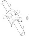
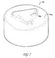
- FIG. 1is an isometric view of to an embodiment of the present invention
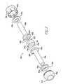
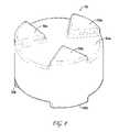
- FIG. 2is an exploded view of the components of an embodiment of the present invention.
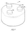
- FIG. 3is a side view of an embodiment of the present invention.
- FIG. 4is a view of an embodiment of the present invention taken along line 4 - 4 of FIG. 3 .
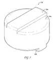
- FIG. 5is an isometric view of an embodiment of the central element of the present invention.
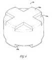
- FIG. 6is an alternative embodiment of the central element of the present invention.
- FIG. 7is an alternative embodiment of the central element of the present invention.
- FIG. 8is an alternative embodiment of the central element of the present invention.
- FIG. 9is an alternative embodiment of the central element of the present invention.
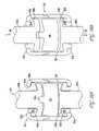
- FIG. 10Ais a cross section view showing an embodiment of the present invention in an unloaded state.
- FIG. 10Bis a cross section view showing an embodiment of the present invention under tension.
- FIG. 11Ais a cross section view showing an embodiment of the present invention in compression.
- FIG. 11Bis a cross section view showing an embodiment of the present invention in a further compressed state.
- FIG. 12is a posterior view showing an embodiment of the present invention placed on a section of the spine.
- FIG. 13is a side view showing an embodiment of the present invention placed on a section of the spine whereby the section of the spine is in flexion.
- FIG. 14is a side view showing an embodiment of the present invention placed on a section of the spine whereby the section of the spine is in extension.
- FIG. 15is a posterior view showing an embodiment of the present invention placed on a section of the spine whereby the section of the spine experiences lateral bending.
- FIG. 16is a posterior view showing an embodiment of the present invention placed on a section of the spine whereby the section of the spine experiences axial rotation.
- FIG. 17is a cross section view showing an embodiment of the present invention actuated under shear.
- FIG. 18is a cross section view showing an embodiment of the present invention angulated.
- the apparatus 10 of the present inventiongenerally comprises elongated members 40 a, b mounted within a housing 20 .
- a central element 50 having elastic propertiesis disposed between the proximal ends of the two elongated members 40 a, b .
- At least one additional flexible or compressible element 30 a, bis mounted about the proximal end of the elongated members 40 a, b adjacent the central element 50 .
- the housing 20encapsulates the proximal ends of the elongated members 40 a, b such that the central element 50 and the at least one additional flexible or compressible element(s) 30 a, b are contained therein.
- the elongated members 40 a, bmay be constructed from materials having sufficient strength and rigidity to resist fracture and plastic deformation under the loads experienced by the spine. Materials such as titanium, titanium alloy, stainless steel or a polymer such as PEEK or carbon fiber may be employed.
- the elongated members 40 a, bmay have a variety of shapes such as cylindrical or polygonal and need not both have the same shape.
- the construction of the components of the apparatus 10may be varied to meet the particular conditions of the patient in which the apparatus 10 will be utilized.
- the material used to construct the central element 50may be varied or the size and shape or the elongated members 40 a, b can be varied such that each member has a different shape or is constructed from a different material.
- one or more of apparatus 10can be mounted between adjacent vertebral bodies 8 a, b in order to provide stability to localized regions of the spine 2 .
- stabilization devicessuch as apparatus 10 are mounted to the vertebral bodies 8 a, b via an anchoring device 3 .
- the devicemay comprise a member having threads at its distal end, not shown in the drawings that allow for attachment to the boney tissue of the spine and a proximal end 4 that accepts the distal ends of elongated members 40 a, b .
- the distal endmay comprise a clamp or other gripping surface.
- a retaining member 6locks the distal ends of the elongated members 40 a, b to the anchoring devices 3 .
- the central element 50 and the additional flexible or compressible elements 30 a, binteract with the elongated members 40 a, b and the housing 20 to stabilize the spine while allowing for controlled movement of the adjacent vertebral bodies 8 a, b.
- the central flexible element 50is situated between the proximal ends of the elongated members 40 a, b .
- the shape of the central element 50is designed to maximize contact with the proximal ends of the elongated members 40 a, b as described in greater detail below, while leaving a space 70 between element 50 and the housing 20 to allow for distortion of the shape of the central flexible element 50 when elongated members 40 a, b are moved inward.
- the central flexible element 50can be homogeneous or made as a composite to tailor its performance to the particular loading apparatus 10 experiences when implanted.
- the central flexible element 50is constructed from an incompressible elastomer such that as elongated members 40 a, b are moved inwards, element 50 experiences transverse strain in response to axial strain.
- a flexible material having a durometer range of 30-65 on the Shore D scale or 20-95 on the Shore A scale and an elongation at break in the range of 200-600% per ASTM D-638may be utilized to construct the central flexible element 50 .
- the material utilizedpreferably is biocompatible and exhibits a consistent dynamic response and resists wear over the millions of loading cycles experience by the apparatus 10 when implanted in the spine.
- One such materialis Polycarbonated Polyurethane or PCU known commercially as Chronoflex.
- Chronoflex C 55DOne grade of Chronoflex that has been shown to function with the present invention is Chronoflex C 55D.
- the central elementis unexpanded when the apparatus 10 is in a neutral, unloaded position.
- element 50eventually expands into space 70 contacting the inner wall of housing 20 .
- the element 50With further movement of the members 40 a, b , the element 50 further expands into interstitial space 28 .
- the expansion of the element 50 into spaces 70 and under certain conditions space 28causes an exponential increase in resistance to compressive loading. This allows for the restricted movement of the adjacent vertebral bodies that apparatus 10 spans while also providing stability thereto.
- the proximal ends of the elongated arms or members 40 a, bare larger than the central and distal portions of the elongated members 40 a, b .
- one or both of the proximal endscomprise flanges 42 a, b .
- the flanges 42 a, binclude outer surfaces 46 a, b facing the distal end of the elongated members 40 a, b and inner surfaces 48 a, b that face the central element 50 .
- the inner surfaces 48 a, b of the flanges 42 a, bmay be convex while the opposing surfaces 54 a, b of the central element 50 are concave.
- the inward surfaces 48 a, bmay be generally concave while the opposing surfaces 54 a, b are convex.
- a variety of shapes for the two surfacesmay be employed including having both surfaces be flat or having non complimentary geometries.
- the shape of the surfaces 48 a, b and 54 a, bwill impact the angular and shear displacement between the elongated members 40 a, b .
- the convex and concave shape of surfaces 48 a, b and 54 a, brespectively act as a rotating joint allowing for articulation as apparatus 10 experiences angular and shear loading.
- the central flexible element 50may include one or more features on surfaces 54 a, b that allows it to interface with the flanges 42 a, b .
- the central element 50includes two ribs 52 a, b on the outer surfaces 54 a, b .
- Each flange 42 a, bincludes a slot 44 a, b that corresponds to the geometry of the ribs 52 a, b such that the ribs are received and under certain conditions engaged therein.
- the ribs 52 a, bengage the slots 44 a, b acting to resist the twisting movement.
- the ribs 52 a, bare oriented orthogonally to each other to allow for more consistent performance in angulation and shear. This also allows for implantation of the device without regard to orientation.
- FIGS. 6-9illustrate examples of geometries that may be employed.
- FIGS. 2 and 6shows a plurality of ribs 56 a, b disposed on the surface 54 a, b such that the amount of surfaces 54 a, b that contact the inner surfaces 48 a, b are minimized.
- FIG. 7shows the central flexible element 50 with centrally located polygons 58 a, b .
- the polygons 58 a, bmay have any number of sides, for example, forming a star with a plurality of points.
- the central flexible element 50has a plurality of polygons 58 a, b located at the perimeter of central element 50 .
- polygons 58 a, bare shown with three sides but could be any number of sides and need not match each other and not be arranged in any pattern.
- FIG. 9shows the central flexible element 50 with a plurality of cylindrical protrusions 60 a, b positioned in a pattern about the surface 54 a, b of the central flexible element 50 .
- the cylindrical protrusionsmay be arranged in any manner and need not follow a pattern.
- the type of engagement features on one side of the central flexible element 50need not match the engagement features on the opposite side.
- one surface 54 a amay have a cruciform 56 a while the other surface 54 b has multiple polygons 58 b .
- the surfaces 54 a, bcan each have different types of features such as polygons and cylindrical protrusions thereon.
- a flexible element or elements 30 a, bis mounted about the proximal end of one or both of the elongated members 40 a, b .
- the flexible elements 30 a, bcomprise a collar 34 a, b and a central region 36 a, b each interacting with housing 20 depending upon the movement of the elongated members 40 a, b .
- the central region 36 a, b of the flexible elements 30 a, bis acted upon when the elongated members 40 a, b are moved in an axial direction.
- the collar 34 a, bmay protrude slightly beyond the margin of the housing 20 and is acted upon when the elongated members 40 a, b are moved in an angular or radial direction.
- one or both of the flexible elements 30 a, bmay be constructed form a Newtonian material whereby transverse strain in response to axial strain is described by Poisson's ratio.
- a spacemay exist between the surfaces 32 a, b and 46 a, b , not shown in the drawings, to allow for greater unrestricted axial movement of elongated members 40 a, b .
- FIG. 10Billustrates the elongated members 40 a, b subjected to an axial force causing the members 40 a, b to move distally in the direction of arrow 61 such as would be experience when the spine is flexed.
- the outer surfaces of flanges 46 a, bpushes on the flexible members 30 a, b at contact surfaces 32 a, b .
- the expansion of the flexible members 30 a, b into space 28 and through the ends 21 a, b of housing 20causes an exponential increase in resistance to axial loading. This allows for the restricted and stabilized movement of adjacent vertebral bodies.
- a variety of shapes and sizescan be employed for the outer surfaces 46 a, b of the flanges 42 a, b and the corresponding contacting surface 32 a, b of the flexible elements 30 a, b .
- the shape of these surfacesmay be varied in order to create a desired dynamic response. Providing a concave shape on surfaces 32 a, b may lead to a more rapid deformation of the flexible elements 30 a, b and, consequentially more rapid stiffening to limit the range of motion for the elongated members 40 a, b .
- a convex shapemay be utilized whereby the flanges 42 a, b have a thinner profile allowing for the flexible elements 30 a, b to be larger. This may provide for a greater range of motion to the elongated members 40 a, b.
- the housing 20may be generally cylindrical and has openings at each end 21 a, b allowing elongated members 40 a, b to pass there through.
- the housing 20is constructed from a generally rigid material that will not deform under the physiological loading encountered within the spine.
- the housing 20may be formed from a first 20 a and a second 20 b casing wherein each of the casings 20 a , 20 b have an opening at ends 21 a, b .
- casing 20 aincludes a locking feature 22 that corresponds to a locking feature 24 on casing 20 b so as to form a snap lock.
- Casing 20 balso includes a plurality of expansion slots 26 that aid in assembly of the apparatus as will be described below.
- the apparatus 10is assembled by aligning the proximal ends of elongated members 40 a, b with the central flexible element 50 such that the protrusions 52 a, b correspond to slots 44 a, b .
- the flexible elements 30 a, bwhich have an opening in the center corresponding to the cross sectional geometry of elongated members 40 a, b , are then inserted over the distal ends of elongated members 40 a, b and slid into place about the proximal end thereof or in proximity to flanges 42 a, b .
- elongated members 40 a, bare placed through the openings in the ends 21 a, b of casings 20 a, b .
- the openings in the ends 21 a, bare larger than the cross sectional geometry of the elongated members 40 a, b creating a space between the elongated members 40 a, b and the housing 20 .
- Casings 20 a, bare placed together and inward pressure applied thereon such that locking features 22 slides under locking feature 24 which moves in a radial direction as facilitated by expansion slots 26 locking casings 20 a, b together.
- the casingscan also be assembled by welding, bolting, threading, screwing, adhesive bonding, magnetic coupling, clamping, or twist locking.
- FIG. 12illustrates the apparatus 10 implanted in the spine between adjacent vertebral bodies 8 a, b in order to provide stability to the joint existing between vertebrae 8 a, b .
- stabilization devicessuch as apparatus 10 are mounted to the vertebral bodies 8 a, b via an anchoring device 3 .
- the apparatus 10serves to stabilize adjacent vertebral bodies while also allowing for motion.
- FIGS. 10A-Bwhen the spine 2 is moved in the direction of arrows 11 the elongated members 40 a, b transfer force to the flexible elements 30 a,b as described above allowing for a limited range of motion.
- FIGS. 11A-B and 14when the spine is moved in the direction of arrows 12 or placed in extension the elongated members 40 a, b moved toward the central flexible element 50 .
- the central flexible element 50expands into spaces 70 and under certain conditions, for example increased extension of the spine creating the dynamic response discussed above.
- FIG. 15the spine 2 is experiencing lateral or side bending, as indicated by the arrows 13 . Under the lateral loading shown in FIG. 15 apparatus 10 a will transfer the loading forces to flexible members 30 a, b while the apparatus 10 b will transfer loading to the central flexible element 50 .
- FIG. 16shows the spine rotated about its axis in the direction of arrow 14 . Due to the apparatus 10 being mounted away from the axis of the spine the device 10 experiences shear loading. As shown in FIG. 17 the elongated members 40 a, b are moved in the direction indicated by arrows 63 . As the elongated members 40 a, b are moved, surfaces 48 a, b and 54 a, b shift relative to each other such that flange 42 a, b is free to interact with additional flexible elements 30 a, b . As the flanges 42 a, b contact additional flexible elements 30 a, b , they impinge upon the housing 20 .
- the additional flexible elements 30 a, bresist movement in the manner described above with reference to the distal movement of the elongated members 40 a, b .
- This dynamic responsemaintains the elongated members 40 a, b roughly parallel to each other as the central flexible element 50 and the housing 20 rotate.
- Apparatus 10has been described above primarily with reference to unidirectional loading conditions. As shown in FIG. 18 , however, the apparatus 10 can handle loading in multiple directions simultaneously. For example, as shown in FIG. 13 the elongated members 40 a, b are moved both distally and obliquely from each other causing the additional flexible elements 30 a, b interact with the flanges 42 a, b and the housing 20 in a manner as described above.
Landscapes
- Health & Medical Sciences (AREA)
- Orthopedic Medicine & Surgery (AREA)
- Life Sciences & Earth Sciences (AREA)
- Neurology (AREA)
- Surgery (AREA)
- Heart & Thoracic Surgery (AREA)
- Engineering & Computer Science (AREA)
- Biomedical Technology (AREA)
- Nuclear Medicine, Radiotherapy & Molecular Imaging (AREA)
- Medical Informatics (AREA)
- Molecular Biology (AREA)
- Animal Behavior & Ethology (AREA)
- General Health & Medical Sciences (AREA)
- Public Health (AREA)
- Veterinary Medicine (AREA)
- Surgical Instruments (AREA)
- Prostheses (AREA)
Abstract
Description
Claims (30)
Priority Applications (8)
| Application Number | Priority Date | Filing Date | Title |
|---|---|---|---|
| US12/190,423US8287571B2 (en) | 2008-08-12 | 2008-08-12 | Apparatus for stabilizing vertebral bodies |
| ES09807249.9TES2560458T3 (en) | 2008-08-12 | 2009-08-12 | Apparatus for stabilizing vertebral bodies |
| JP2011523147AJP5612577B2 (en) | 2008-08-12 | 2009-08-12 | Device for stabilizing the vertebral body |
| PCT/US2009/053600WO2010019704A1 (en) | 2008-08-12 | 2009-08-12 | Apparatus for stabilizing vertebral bodies |
| AU2009281979AAU2009281979B2 (en) | 2008-08-12 | 2009-08-12 | Apparatus for stabilizing vertebral bodies |
| EP09807249.9AEP2320814B1 (en) | 2008-08-12 | 2009-08-12 | Apparatus for stabilizing vertebral bodies |
| US13/651,640US9050140B2 (en) | 2008-08-12 | 2012-10-15 | Apparatus for stabilizing vertebral bodies |
| JP2014180239AJP6076948B2 (en) | 2008-08-12 | 2014-09-04 | Device for stabilizing the vertebral body |
Applications Claiming Priority (1)
| Application Number | Priority Date | Filing Date | Title |
|---|---|---|---|
| US12/190,423US8287571B2 (en) | 2008-08-12 | 2008-08-12 | Apparatus for stabilizing vertebral bodies |
Related Child Applications (1)
| Application Number | Title | Priority Date | Filing Date |
|---|---|---|---|
| US13/651,640ContinuationUS9050140B2 (en) | 2008-08-12 | 2012-10-15 | Apparatus for stabilizing vertebral bodies |
Publications (2)
| Publication Number | Publication Date |
|---|---|
| US20100042152A1 US20100042152A1 (en) | 2010-02-18 |
| US8287571B2true US8287571B2 (en) | 2012-10-16 |
Family
ID=41669276
Family Applications (2)
| Application Number | Title | Priority Date | Filing Date |
|---|---|---|---|
| US12/190,423Active2031-07-19US8287571B2 (en) | 2008-08-12 | 2008-08-12 | Apparatus for stabilizing vertebral bodies |
| US13/651,640ActiveUS9050140B2 (en) | 2008-08-12 | 2012-10-15 | Apparatus for stabilizing vertebral bodies |
Family Applications After (1)
| Application Number | Title | Priority Date | Filing Date |
|---|---|---|---|
| US13/651,640ActiveUS9050140B2 (en) | 2008-08-12 | 2012-10-15 | Apparatus for stabilizing vertebral bodies |
Country Status (6)
| Country | Link |
|---|---|
| US (2) | US8287571B2 (en) |
| EP (1) | EP2320814B1 (en) |
| JP (2) | JP5612577B2 (en) |
| AU (1) | AU2009281979B2 (en) |
| ES (1) | ES2560458T3 (en) |
| WO (1) | WO2010019704A1 (en) |
Cited By (4)
| Publication number | Priority date | Publication date | Assignee | Title |
|---|---|---|---|---|
| US8709048B2 (en)* | 2010-08-20 | 2014-04-29 | Tongji University | Rod system for gradual dynamic spinal fixation |
| US20180071106A1 (en)* | 2016-09-13 | 2018-03-15 | Mayo Foundation For Medical Education And Research | Facet joint replacement devices |
| US11583318B2 (en) | 2018-12-21 | 2023-02-21 | Paradigm Spine, Llc | Modular spine stabilization system and associated instruments |
| US11737793B2 (en)* | 2017-10-20 | 2023-08-29 | Mayo Foundation For Medical Education And Research | Facet joint replacement devices |
Families Citing this family (57)
| Publication number | Priority date | Publication date | Assignee | Title |
|---|---|---|---|---|
| US7833250B2 (en) | 2004-11-10 | 2010-11-16 | Jackson Roger P | Polyaxial bone screw with helically wound capture connection |
| US10729469B2 (en) | 2006-01-09 | 2020-08-04 | Roger P. Jackson | Flexible spinal stabilization assembly with spacer having off-axis core member |
| US10258382B2 (en) | 2007-01-18 | 2019-04-16 | Roger P. Jackson | Rod-cord dynamic connection assemblies with slidable bone anchor attachment members along the cord |
| US7862587B2 (en) | 2004-02-27 | 2011-01-04 | Jackson Roger P | Dynamic stabilization assemblies, tool set and method |
| US8353932B2 (en) | 2005-09-30 | 2013-01-15 | Jackson Roger P | Polyaxial bone anchor assembly with one-piece closure, pressure insert and plastic elongate member |
| US8876868B2 (en) | 2002-09-06 | 2014-11-04 | Roger P. Jackson | Helical guide and advancement flange with radially loaded lip |
| US7621918B2 (en) | 2004-11-23 | 2009-11-24 | Jackson Roger P | Spinal fixation tool set and method |
| US7377923B2 (en) | 2003-05-22 | 2008-05-27 | Alphatec Spine, Inc. | Variable angle spinal screw assembly |
| US8926670B2 (en) | 2003-06-18 | 2015-01-06 | Roger P. Jackson | Polyaxial bone screw assembly |
| US7776067B2 (en) | 2005-05-27 | 2010-08-17 | Jackson Roger P | Polyaxial bone screw with shank articulation pressure insert and method |
| US7766915B2 (en) | 2004-02-27 | 2010-08-03 | Jackson Roger P | Dynamic fixation assemblies with inner core and outer coil-like member |
| US7179261B2 (en) | 2003-12-16 | 2007-02-20 | Depuy Spine, Inc. | Percutaneous access devices and bone anchor assemblies |
| US11419642B2 (en) | 2003-12-16 | 2022-08-23 | Medos International Sarl | Percutaneous access devices and bone anchor assemblies |
| US7527638B2 (en) | 2003-12-16 | 2009-05-05 | Depuy Spine, Inc. | Methods and devices for minimally invasive spinal fixation element placement |
| JP2007525274A (en) | 2004-02-27 | 2007-09-06 | ロジャー・ピー・ジャクソン | Orthopedic implant rod reduction instrument set and method |
| US7160300B2 (en) | 2004-02-27 | 2007-01-09 | Jackson Roger P | Orthopedic implant rod reduction tool set and method |
| US11241261B2 (en) | 2005-09-30 | 2022-02-08 | Roger P Jackson | Apparatus and method for soft spinal stabilization using a tensionable cord and releasable end structure |
| US8152810B2 (en) | 2004-11-23 | 2012-04-10 | Jackson Roger P | Spinal fixation tool set and method |
| US7651502B2 (en) | 2004-09-24 | 2010-01-26 | Jackson Roger P | Spinal fixation tool set and method for rod reduction and fastener insertion |
| US8926672B2 (en) | 2004-11-10 | 2015-01-06 | Roger P. Jackson | Splay control closure for open bone anchor |
| US8444681B2 (en) | 2009-06-15 | 2013-05-21 | Roger P. Jackson | Polyaxial bone anchor with pop-on shank, friction fit retainer and winged insert |
| US9216041B2 (en) | 2009-06-15 | 2015-12-22 | Roger P. Jackson | Spinal connecting members with tensioned cords and rigid sleeves for engaging compression inserts |
| WO2006057837A1 (en) | 2004-11-23 | 2006-06-01 | Jackson Roger P | Spinal fixation tool attachment structure |
| US9168069B2 (en) | 2009-06-15 | 2015-10-27 | Roger P. Jackson | Polyaxial bone anchor with pop-on shank and winged insert with lower skirt for engaging a friction fit retainer |
| US7901437B2 (en) | 2007-01-26 | 2011-03-08 | Jackson Roger P | Dynamic stabilization member with molded connection |
| US8105368B2 (en) | 2005-09-30 | 2012-01-31 | Jackson Roger P | Dynamic stabilization connecting member with slitted core and outer sleeve |
| CA2670988C (en) | 2006-12-08 | 2014-03-25 | Roger P. Jackson | Tool system for dynamic spinal implants |
| US8366745B2 (en) | 2007-05-01 | 2013-02-05 | Jackson Roger P | Dynamic stabilization assembly having pre-compressed spacers with differential displacements |
| US8475498B2 (en) | 2007-01-18 | 2013-07-02 | Roger P. Jackson | Dynamic stabilization connecting member with cord connection |
| US10383660B2 (en) | 2007-05-01 | 2019-08-20 | Roger P. Jackson | Soft stabilization assemblies with pretensioned cords |
| US8979904B2 (en) | 2007-05-01 | 2015-03-17 | Roger P Jackson | Connecting member with tensioned cord, low profile rigid sleeve and spacer with torsion control |
| AU2010260521C1 (en) | 2008-08-01 | 2013-08-01 | Roger P. Jackson | Longitudinal connecting member with sleeved tensioned cords |
| US8425562B2 (en)* | 2009-04-13 | 2013-04-23 | Warsaw Orthopedic, Inc. | Systems and devices for dynamic stabilization of the spine |
| US11229457B2 (en) | 2009-06-15 | 2022-01-25 | Roger P. Jackson | Pivotal bone anchor assembly with insert tool deployment |
| US9668771B2 (en) | 2009-06-15 | 2017-06-06 | Roger P Jackson | Soft stabilization assemblies with off-set connector |
| US8998959B2 (en) | 2009-06-15 | 2015-04-07 | Roger P Jackson | Polyaxial bone anchors with pop-on shank, fully constrained friction fit retainer and lock and release insert |
| CN103826560A (en) | 2009-06-15 | 2014-05-28 | 罗杰.P.杰克逊 | Polyaxial Bone Anchor with Socket Stem and Winged Inserts with Friction Fit Compression Collars |
| EP2485654B1 (en) | 2009-10-05 | 2021-05-05 | Jackson P. Roger | Polyaxial bone anchor with non-pivotable retainer and pop-on shank, some with friction fit |
| CH703411A2 (en)* | 2010-07-12 | 2012-01-13 | Spinelab Ag | Spinal implant with pedicle screws and the corresponding pedicle screw. |
| AU2011299558A1 (en) | 2010-09-08 | 2013-05-02 | Roger P. Jackson | Dynamic stabilization members with elastic and inelastic sections |
| FR2969479B1 (en)* | 2010-12-23 | 2013-11-22 | Univ Claude Bernard Lyon | DEVICE FOR CORRECTING SCOLIOSIS AND FIGHT AGAINST ARTHRODESIS OF VERTEBRATES |
| US8894688B2 (en)* | 2011-10-27 | 2014-11-25 | Globus Medical Inc. | Adjustable rod devices and methods of using the same |
| US8911479B2 (en) | 2012-01-10 | 2014-12-16 | Roger P. Jackson | Multi-start closures for open implants |
| US9232966B2 (en)* | 2012-09-24 | 2016-01-12 | Refai Technologies, Llc | Articulating spinal rod system |
| US9023087B2 (en) | 2012-11-09 | 2015-05-05 | Blackstone Medical, Inc. | Percutaneous modular head-to-head cross connector |
| US8911478B2 (en) | 2012-11-21 | 2014-12-16 | Roger P. Jackson | Splay control closure for open bone anchor |
| US10058354B2 (en) | 2013-01-28 | 2018-08-28 | Roger P. Jackson | Pivotal bone anchor assembly with frictional shank head seating surfaces |
| US8852239B2 (en) | 2013-02-15 | 2014-10-07 | Roger P Jackson | Sagittal angle screw with integral shank and receiver |
| US9908963B2 (en) | 2013-04-12 | 2018-03-06 | Mereck Patent Gmbh | Particles for electrophoretic displays |
| WO2015023420A2 (en) | 2013-07-25 | 2015-02-19 | Latitude Holdings, Llc | Percutaneous pedicle screw revision system |
| US9566092B2 (en) | 2013-10-29 | 2017-02-14 | Roger P. Jackson | Cervical bone anchor with collet retainer and outer locking sleeve |
| US9717533B2 (en) | 2013-12-12 | 2017-08-01 | Roger P. Jackson | Bone anchor closure pivot-splay control flange form guide and advancement structure |
| US9451993B2 (en) | 2014-01-09 | 2016-09-27 | Roger P. Jackson | Bi-radial pop-on cervical bone anchor |
| US9597119B2 (en) | 2014-06-04 | 2017-03-21 | Roger P. Jackson | Polyaxial bone anchor with polymer sleeve |
| US10064658B2 (en) | 2014-06-04 | 2018-09-04 | Roger P. Jackson | Polyaxial bone anchor with insert guides |
| US9603634B1 (en) | 2015-11-13 | 2017-03-28 | Amendia, Inc. | Percutaneous rod-to-rod cross connector |
| TWI805309B (en)* | 2022-04-07 | 2023-06-11 | 碩果生醫科技有限公司 | Spine connecting rod |
Citations (80)
| Publication number | Priority date | Publication date | Assignee | Title |
|---|---|---|---|---|
| US4743260A (en) | 1985-06-10 | 1988-05-10 | Burton Charles V | Method for a flexible stabilization system for a vertebral column |
| US5034011A (en) | 1990-08-09 | 1991-07-23 | Advanced Spine Fixation Systems Incorporated | Segmental instrumentation of the posterior spine |
| US5092866A (en) | 1989-02-03 | 1992-03-03 | Breard Francis H | Flexible inter-vertebral stabilizer as well as process and apparatus for determining or verifying its tension before installation on the spinal column |
| US5180393A (en) | 1990-09-21 | 1993-01-19 | Polyclinique De Bourgogne & Les Hortensiad | Artificial ligament for the spine |
| US5242446A (en) | 1992-01-02 | 1993-09-07 | Acromed Corporation | Connector for a spinal column corrective device |
| US5375823A (en) | 1992-06-25 | 1994-12-27 | Societe Psi | Application of an improved damper to an intervertebral stabilization device |
| US5415661A (en) | 1993-03-24 | 1995-05-16 | University Of Miami | Implantable spinal assist device |
| US5480442A (en)* | 1993-06-24 | 1996-01-02 | Man Ceramics Gmbh | Fixedly adjustable intervertebral prosthesis |
| US5480401A (en) | 1993-02-17 | 1996-01-02 | Psi | Extra-discal inter-vertebral prosthesis for controlling the variations of the inter-vertebral distance by means of a double damper |
| US5507816A (en) | 1991-12-04 | 1996-04-16 | Customflex Limited | Spinal vertebrae implants |
| US5540688A (en) | 1991-05-30 | 1996-07-30 | Societe "Psi" | Intervertebral stabilization device incorporating dampers |
| FR2730918A1 (en) | 1995-02-24 | 1996-08-30 | Alby Luc | Flexible inter-vertebral connector implant with controlled movement, for correcting defects in vertebral posture |
| US5562737A (en) | 1993-11-18 | 1996-10-08 | Henry Graf | Extra-discal intervertebral prosthesis |
| US5672175A (en) | 1993-08-27 | 1997-09-30 | Martin; Jean Raymond | Dynamic implanted spinal orthosis and operative procedure for fitting |
| US5961516A (en) | 1996-08-01 | 1999-10-05 | Graf; Henry | Device for mechanically connecting and assisting vertebrae with respect to one another |
| US6241730B1 (en)* | 1997-11-26 | 2001-06-05 | Scient'x (Societe A Responsabilite Limitee) | Intervertebral link device capable of axial and angular displacement |
| US6267764B1 (en) | 1996-11-15 | 2001-07-31 | Stryker France S.A. | Osteosynthesis system with elastic deformation for spinal column |
| US6293949B1 (en) | 2000-03-01 | 2001-09-25 | Sdgi Holdings, Inc. | Superelastic spinal stabilization system and method |
| FR2814936A1 (en) | 2000-10-11 | 2002-04-12 | Frederic Fortin | Supple one-piece vertebral connector has central core with elastic fibres, fixings and polymerised resin covering |
| US6443437B1 (en)* | 2000-05-17 | 2002-09-03 | Lord Corporation | Suspension strut with damping |
| US20040002708A1 (en) | 2002-05-08 | 2004-01-01 | Stephen Ritland | Dynamic fixation device and method of use |
| US20040049189A1 (en) | 2000-07-25 | 2004-03-11 | Regis Le Couedic | Flexible linking piece for stabilising the spine |
| US20040243127A1 (en)* | 2001-01-23 | 2004-12-02 | Stryker Spine | Position-adjustment device with applicability for surgical instrumentation |
| US20050056979A1 (en) | 2001-12-07 | 2005-03-17 | Mathys Medizinaltechnik Ag | Damping element and device for stabilisation of adjacent vertebral bodies |
| US20050096659A1 (en) | 2003-10-31 | 2005-05-05 | Stefan Freudiger | Pedicle screw with a closure device for the fixing of elastic rod elements |
| US20050131407A1 (en) | 2003-12-16 | 2005-06-16 | Sicvol Christopher W. | Flexible spinal fixation elements |
| US20050165396A1 (en)* | 2001-07-18 | 2005-07-28 | Frederic Fortin | Flexible vertebral linking device |
| US20050171540A1 (en) | 2004-01-30 | 2005-08-04 | Roy Lim | Instruments and methods for minimally invasive spinal stabilization |
| US20050171543A1 (en) | 2003-05-02 | 2005-08-04 | Timm Jens P. | Spine stabilization systems and associated devices, assemblies and methods |
| US20050182401A1 (en)* | 2003-05-02 | 2005-08-18 | Timm Jens P. | Systems and methods for spine stabilization including a dynamic junction |
| US20050277922A1 (en)* | 2004-06-09 | 2005-12-15 | Trieu Hai H | Systems and methods for flexible spinal stabilization |
| US6986771B2 (en) | 2003-05-23 | 2006-01-17 | Globus Medical, Inc. | Spine stabilization system |
| US20060036240A1 (en) | 2004-08-09 | 2006-02-16 | Innovative Spinal Technologies | System and method for dynamic skeletal stabilization |
| US7029475B2 (en) | 2003-05-02 | 2006-04-18 | Yale University | Spinal stabilization method |
| US20060084984A1 (en) | 2004-10-20 | 2006-04-20 | The Board Of Trustees For The Leland Stanford Junior University | Systems and methods for posterior dynamic stabilization of the spine |
| US20060084991A1 (en) | 2004-09-30 | 2006-04-20 | Depuy Spine, Inc. | Posterior dynamic stabilizer devices |
| US20060142760A1 (en) | 2004-12-15 | 2006-06-29 | Stryker Spine | Methods and apparatus for modular and variable spinal fixation |
| US20060149238A1 (en) | 2005-01-04 | 2006-07-06 | Sherman Michael C | Systems and methods for spinal stabilization with flexible elements |
| US7083621B2 (en) | 2003-04-25 | 2006-08-01 | Sdgi Holdings, Inc. | Articulating spinal fixation rod and system |
| US20060189984A1 (en) | 2005-02-22 | 2006-08-24 | Medicinelodge, Inc. | Apparatus and method for dynamic vertebral stabilization |
| US20060212033A1 (en) | 2005-03-03 | 2006-09-21 | Accin Corporation | Vertebral stabilization using flexible rods |
| US20060229609A1 (en) | 2005-03-18 | 2006-10-12 | Chao-Jan Wang | Microadjustment spinal joint fixture |
| US7125410B2 (en) | 2002-05-21 | 2006-10-24 | Spinelab Gmbh | Elastic stabilization system for vertebral columns |
| US20060247637A1 (en) | 2004-08-09 | 2006-11-02 | Dennis Colleran | System and method for dynamic skeletal stabilization |
| US20060264940A1 (en)* | 2003-09-29 | 2006-11-23 | Stephan Hartmann | Dynamic damping element for two bones |
| US20060264935A1 (en) | 2005-05-04 | 2006-11-23 | White Patrick M | Orthopedic stabilization device |
| US20070016190A1 (en) | 2005-07-14 | 2007-01-18 | Medical Device Concepts Llc | Dynamic spinal stabilization system |
| US20070049936A1 (en) | 2005-08-26 | 2007-03-01 | Dennis Colleran | Alignment instrument for dynamic spinal stabilization systems |
| US20070055244A1 (en) | 2004-02-27 | 2007-03-08 | Jackson Roger P | Dynamic fixation assemblies with inner core and outer coil-like member |
| US20070093813A1 (en) | 2005-10-11 | 2007-04-26 | Callahan Ronald Ii | Dynamic spinal stabilizer |
| US20070100341A1 (en)* | 2004-10-20 | 2007-05-03 | Reglos Joey C | Systems and methods for stabilization of bone structures |
| US20070123866A1 (en) | 2005-10-31 | 2007-05-31 | Stryker Spine | System and method for dynamic vertebral stabilization |
| US20070191846A1 (en) | 2006-01-31 | 2007-08-16 | Aurelien Bruneau | Expandable spinal rods and methods of use |
| US20070191832A1 (en) | 2006-01-27 | 2007-08-16 | Sdgi Holdings, Inc. | Vertebral rods and methods of use |
| US20070225710A1 (en) | 2003-09-24 | 2007-09-27 | Tae-Ahn Jahng | Spinal stabilization device |
| US7282065B2 (en) | 2004-04-09 | 2007-10-16 | X-Spine Systems, Inc. | Disk augmentation system and method |
| US7291150B2 (en)* | 1999-12-01 | 2007-11-06 | Sdgi Holdings, Inc. | Intervertebral stabilising device |
| US7294129B2 (en) | 2005-02-18 | 2007-11-13 | Ebi, L.P. | Spinal fixation device and associated method |
| US20070270860A1 (en) | 2005-09-30 | 2007-11-22 | Jackson Roger P | Dynamic stabilization connecting member with slitted core and outer sleeve |
| US20070270814A1 (en) | 2006-04-20 | 2007-11-22 | Sdgi Holdings, Inc. | Vertebral stabilizer |
| US20070270821A1 (en) | 2006-04-28 | 2007-11-22 | Sdgi Holdings, Inc. | Vertebral stabilizer |
| US20070276380A1 (en) | 2003-09-24 | 2007-11-29 | Tae-Ahn Jahng | Spinal stabilization device |
| US20070288011A1 (en) | 2006-04-18 | 2007-12-13 | Joseph Nicholas Logan | Spinal Rod System |
| US20070288008A1 (en) | 2004-09-22 | 2007-12-13 | Kyung-Woo Park | Semi-rigid spinal fixation apparatus |
| US7326250B2 (en) | 2001-05-04 | 2008-02-05 | Ldr Medical | Intervertebral disc prosthesis and fitting tools |
| US7338527B2 (en) | 2004-05-11 | 2008-03-04 | Geoffrey Blatt | Artificial spinal disc, insertion tool, and method of insertion |
| US20080097441A1 (en) | 2004-10-20 | 2008-04-24 | Stanley Kyle Hayes | Systems and methods for posterior dynamic stabilization of the spine |
| US20080125777A1 (en) | 2006-11-27 | 2008-05-29 | Warsaw Orthopedic, Inc. | Vertebral Stabilizer Having Adjustable Rigidity |
| US20080140076A1 (en)* | 2005-09-30 | 2008-06-12 | Jackson Roger P | Dynamic stabilization connecting member with slitted segment and surrounding external elastomer |
| US20080147122A1 (en)* | 2006-10-12 | 2008-06-19 | Jackson Roger P | Dynamic stabilization connecting member with molded inner segment and surrounding external elastomer |
| US20080172091A1 (en)* | 2007-01-12 | 2008-07-17 | Warsaw Orthopedic, Inc. | Spinal Stabilization System |
| US20080177318A1 (en) | 2007-01-18 | 2008-07-24 | Warsaw Orthopedic, Inc. | Vertebral Stabilizer |
| US20080183213A1 (en)* | 2007-01-30 | 2008-07-31 | Warsaw Orthopedic, Inc. | Collar Bore Configuration for Dynamic Spinal Stabilization Assembly |
| US20080195208A1 (en)* | 2007-02-09 | 2008-08-14 | Altiva Corporation | Dynamic stabilization device |
| US20090048631A1 (en)* | 2007-08-17 | 2009-02-19 | Bhatnagar Mohit K | Dynamic Stabilization Device for Spine |
| US20090099608A1 (en)* | 2007-10-12 | 2009-04-16 | Aesculap Implant Systems, Inc. | Rod assembly for dynamic posterior stabilization |
| US20090234388A1 (en)* | 2008-03-15 | 2009-09-17 | Warsaw Orthopedic, Inc. | Spinal Stabilization Connecting Element and System |
| US7597027B2 (en)* | 2007-07-19 | 2009-10-06 | Young Dae Kwon | Isolator for a motion transmitting remote control assembly |
| US20090326583A1 (en)* | 2008-06-25 | 2009-12-31 | Missoum Moumene | Posterior Dynamic Stabilization System With Flexible Ligament |
| US20100069964A1 (en)* | 2006-06-28 | 2010-03-18 | Beat Lechmann | Dynamic fixation system |
Family Cites Families (4)
| Publication number | Priority date | Publication date | Assignee | Title |
|---|---|---|---|---|
| WO2007061960A2 (en)* | 2005-11-18 | 2007-05-31 | Life Spine, Inc. | Dynamic spinal stabilization devices and systems |
| EP1815812B1 (en)* | 2006-02-03 | 2009-07-29 | Spinelab AG | Spinal implant |
| AU2007223928C1 (en)* | 2006-03-08 | 2011-10-13 | Blackstone Medical, Inc. | System and method for dynamic stabilization of the spine |
| US20080125787A1 (en)* | 2006-11-27 | 2008-05-29 | Doubler Robert L | Dynamic rod |
- 2008
- 2008-08-12USUS12/190,423patent/US8287571B2/enactiveActive
- 2009
- 2009-08-12EPEP09807249.9Apatent/EP2320814B1/ennot_activeNot-in-force
- 2009-08-12AUAU2009281979Apatent/AU2009281979B2/ennot_activeCeased
- 2009-08-12WOPCT/US2009/053600patent/WO2010019704A1/enactiveApplication Filing
- 2009-08-12JPJP2011523147Apatent/JP5612577B2/ennot_activeExpired - Fee Related
- 2009-08-12ESES09807249.9Tpatent/ES2560458T3/enactiveActive
- 2012
- 2012-10-15USUS13/651,640patent/US9050140B2/enactiveActive
- 2014
- 2014-09-04JPJP2014180239Apatent/JP6076948B2/ennot_activeExpired - Fee Related
Patent Citations (91)
| Publication number | Priority date | Publication date | Assignee | Title |
|---|---|---|---|---|
| US5282863A (en) | 1985-06-10 | 1994-02-01 | Charles V. Burton | Flexible stabilization system for a vertebral column |
| US4743260A (en) | 1985-06-10 | 1988-05-10 | Burton Charles V | Method for a flexible stabilization system for a vertebral column |
| US5092866A (en) | 1989-02-03 | 1992-03-03 | Breard Francis H | Flexible inter-vertebral stabilizer as well as process and apparatus for determining or verifying its tension before installation on the spinal column |
| US5034011A (en) | 1990-08-09 | 1991-07-23 | Advanced Spine Fixation Systems Incorporated | Segmental instrumentation of the posterior spine |
| US5180393A (en) | 1990-09-21 | 1993-01-19 | Polyclinique De Bourgogne & Les Hortensiad | Artificial ligament for the spine |
| US5540688A (en) | 1991-05-30 | 1996-07-30 | Societe "Psi" | Intervertebral stabilization device incorporating dampers |
| US5507816A (en) | 1991-12-04 | 1996-04-16 | Customflex Limited | Spinal vertebrae implants |
| US5242446A (en) | 1992-01-02 | 1993-09-07 | Acromed Corporation | Connector for a spinal column corrective device |
| US5375823A (en) | 1992-06-25 | 1994-12-27 | Societe Psi | Application of an improved damper to an intervertebral stabilization device |
| US5480401A (en) | 1993-02-17 | 1996-01-02 | Psi | Extra-discal inter-vertebral prosthesis for controlling the variations of the inter-vertebral distance by means of a double damper |
| US5415661A (en) | 1993-03-24 | 1995-05-16 | University Of Miami | Implantable spinal assist device |
| US5480442A (en)* | 1993-06-24 | 1996-01-02 | Man Ceramics Gmbh | Fixedly adjustable intervertebral prosthesis |
| US5672175A (en) | 1993-08-27 | 1997-09-30 | Martin; Jean Raymond | Dynamic implanted spinal orthosis and operative procedure for fitting |
| US5562737A (en) | 1993-11-18 | 1996-10-08 | Henry Graf | Extra-discal intervertebral prosthesis |
| FR2730918A1 (en) | 1995-02-24 | 1996-08-30 | Alby Luc | Flexible inter-vertebral connector implant with controlled movement, for correcting defects in vertebral posture |
| US5961516A (en) | 1996-08-01 | 1999-10-05 | Graf; Henry | Device for mechanically connecting and assisting vertebrae with respect to one another |
| US6267764B1 (en) | 1996-11-15 | 2001-07-31 | Stryker France S.A. | Osteosynthesis system with elastic deformation for spinal column |
| US6241730B1 (en)* | 1997-11-26 | 2001-06-05 | Scient'x (Societe A Responsabilite Limitee) | Intervertebral link device capable of axial and angular displacement |
| US7291150B2 (en)* | 1999-12-01 | 2007-11-06 | Sdgi Holdings, Inc. | Intervertebral stabilising device |
| US20080065078A1 (en) | 1999-12-01 | 2008-03-13 | Henry Graf | Intervertebral stabilising device |
| US6761719B2 (en) | 2000-03-01 | 2004-07-13 | Sdgi Holdings, Inc. | Superelastic spinal stabilization system and method |
| US6293949B1 (en) | 2000-03-01 | 2001-09-25 | Sdgi Holdings, Inc. | Superelastic spinal stabilization system and method |
| US6443437B1 (en)* | 2000-05-17 | 2002-09-03 | Lord Corporation | Suspension strut with damping |
| US20040049189A1 (en) | 2000-07-25 | 2004-03-11 | Regis Le Couedic | Flexible linking piece for stabilising the spine |
| FR2814936A1 (en) | 2000-10-11 | 2002-04-12 | Frederic Fortin | Supple one-piece vertebral connector has central core with elastic fibres, fixings and polymerised resin covering |
| US20040243127A1 (en)* | 2001-01-23 | 2004-12-02 | Stryker Spine | Position-adjustment device with applicability for surgical instrumentation |
| US7326250B2 (en) | 2001-05-04 | 2008-02-05 | Ldr Medical | Intervertebral disc prosthesis and fitting tools |
| US20050261685A1 (en) | 2001-07-18 | 2005-11-24 | Frederic Fortin | Flexible vertebral linking device |
| US20050165396A1 (en)* | 2001-07-18 | 2005-07-28 | Frederic Fortin | Flexible vertebral linking device |
| US20050065514A1 (en) | 2001-12-07 | 2005-03-24 | Armin Studer | Damping element |
| US20080033435A1 (en)* | 2001-12-07 | 2008-02-07 | Armin Studer | Damping element and device for stabilization of adjacent vertebral bodies |
| US20050056979A1 (en) | 2001-12-07 | 2005-03-17 | Mathys Medizinaltechnik Ag | Damping element and device for stabilisation of adjacent vertebral bodies |
| US20040002708A1 (en) | 2002-05-08 | 2004-01-01 | Stephen Ritland | Dynamic fixation device and method of use |
| US20070016193A1 (en) | 2002-05-08 | 2007-01-18 | Stephen Ritland | Dynamic fixation device and method of use |
| US20070016201A1 (en) | 2002-05-21 | 2007-01-18 | Spinelab Gmbh | Elastic stabilization system for vertebral columns |
| US7125410B2 (en) | 2002-05-21 | 2006-10-24 | Spinelab Gmbh | Elastic stabilization system for vertebral columns |
| US7083621B2 (en) | 2003-04-25 | 2006-08-01 | Sdgi Holdings, Inc. | Articulating spinal fixation rod and system |
| US20050171543A1 (en) | 2003-05-02 | 2005-08-04 | Timm Jens P. | Spine stabilization systems and associated devices, assemblies and methods |
| US7029475B2 (en) | 2003-05-02 | 2006-04-18 | Yale University | Spinal stabilization method |
| US20050182401A1 (en)* | 2003-05-02 | 2005-08-18 | Timm Jens P. | Systems and methods for spine stabilization including a dynamic junction |
| US6986771B2 (en) | 2003-05-23 | 2006-01-17 | Globus Medical, Inc. | Spine stabilization system |
| US7326210B2 (en) | 2003-09-24 | 2008-02-05 | N Spine, Inc | Spinal stabilization device |
| US20070225710A1 (en) | 2003-09-24 | 2007-09-27 | Tae-Ahn Jahng | Spinal stabilization device |
| US20070276380A1 (en) | 2003-09-24 | 2007-11-29 | Tae-Ahn Jahng | Spinal stabilization device |
| US20060264940A1 (en)* | 2003-09-29 | 2006-11-23 | Stephan Hartmann | Dynamic damping element for two bones |
| US20050096659A1 (en) | 2003-10-31 | 2005-05-05 | Stefan Freudiger | Pedicle screw with a closure device for the fixing of elastic rod elements |
| US20050131407A1 (en) | 2003-12-16 | 2005-06-16 | Sicvol Christopher W. | Flexible spinal fixation elements |
| US20050171540A1 (en) | 2004-01-30 | 2005-08-04 | Roy Lim | Instruments and methods for minimally invasive spinal stabilization |
| US20070055244A1 (en) | 2004-02-27 | 2007-03-08 | Jackson Roger P | Dynamic fixation assemblies with inner core and outer coil-like member |
| US7282065B2 (en) | 2004-04-09 | 2007-10-16 | X-Spine Systems, Inc. | Disk augmentation system and method |
| US7338527B2 (en) | 2004-05-11 | 2008-03-04 | Geoffrey Blatt | Artificial spinal disc, insertion tool, and method of insertion |
| US20050277922A1 (en)* | 2004-06-09 | 2005-12-15 | Trieu Hai H | Systems and methods for flexible spinal stabilization |
| US20060036240A1 (en) | 2004-08-09 | 2006-02-16 | Innovative Spinal Technologies | System and method for dynamic skeletal stabilization |
| US20060247637A1 (en) | 2004-08-09 | 2006-11-02 | Dennis Colleran | System and method for dynamic skeletal stabilization |
| US20070288008A1 (en) | 2004-09-22 | 2007-12-13 | Kyung-Woo Park | Semi-rigid spinal fixation apparatus |
| US20060084991A1 (en) | 2004-09-30 | 2006-04-20 | Depuy Spine, Inc. | Posterior dynamic stabilizer devices |
| US20070100341A1 (en)* | 2004-10-20 | 2007-05-03 | Reglos Joey C | Systems and methods for stabilization of bone structures |
| US20080097441A1 (en) | 2004-10-20 | 2008-04-24 | Stanley Kyle Hayes | Systems and methods for posterior dynamic stabilization of the spine |
| US20060084984A1 (en) | 2004-10-20 | 2006-04-20 | The Board Of Trustees For The Leland Stanford Junior University | Systems and methods for posterior dynamic stabilization of the spine |
| US20060142760A1 (en) | 2004-12-15 | 2006-06-29 | Stryker Spine | Methods and apparatus for modular and variable spinal fixation |
| US20060149238A1 (en) | 2005-01-04 | 2006-07-06 | Sherman Michael C | Systems and methods for spinal stabilization with flexible elements |
| US7294129B2 (en) | 2005-02-18 | 2007-11-13 | Ebi, L.P. | Spinal fixation device and associated method |
| US7361196B2 (en) | 2005-02-22 | 2008-04-22 | Stryker Spine | Apparatus and method for dynamic vertebral stabilization |
| US20060189984A1 (en) | 2005-02-22 | 2006-08-24 | Medicinelodge, Inc. | Apparatus and method for dynamic vertebral stabilization |
| US20060212033A1 (en) | 2005-03-03 | 2006-09-21 | Accin Corporation | Vertebral stabilization using flexible rods |
| US20060229609A1 (en) | 2005-03-18 | 2006-10-12 | Chao-Jan Wang | Microadjustment spinal joint fixture |
| US20060264935A1 (en) | 2005-05-04 | 2006-11-23 | White Patrick M | Orthopedic stabilization device |
| US20070016190A1 (en) | 2005-07-14 | 2007-01-18 | Medical Device Concepts Llc | Dynamic spinal stabilization system |
| US20070049936A1 (en) | 2005-08-26 | 2007-03-01 | Dennis Colleran | Alignment instrument for dynamic spinal stabilization systems |
| US20080140076A1 (en)* | 2005-09-30 | 2008-06-12 | Jackson Roger P | Dynamic stabilization connecting member with slitted segment and surrounding external elastomer |
| US20070270860A1 (en) | 2005-09-30 | 2007-11-22 | Jackson Roger P | Dynamic stabilization connecting member with slitted core and outer sleeve |
| US20070093813A1 (en) | 2005-10-11 | 2007-04-26 | Callahan Ronald Ii | Dynamic spinal stabilizer |
| US20070135815A1 (en) | 2005-10-31 | 2007-06-14 | Stryker Spine | System and method for dynamic vertebral stabilization |
| US20070123866A1 (en) | 2005-10-31 | 2007-05-31 | Stryker Spine | System and method for dynamic vertebral stabilization |
| US20070191832A1 (en) | 2006-01-27 | 2007-08-16 | Sdgi Holdings, Inc. | Vertebral rods and methods of use |
| US20070191846A1 (en) | 2006-01-31 | 2007-08-16 | Aurelien Bruneau | Expandable spinal rods and methods of use |
| US20070288011A1 (en) | 2006-04-18 | 2007-12-13 | Joseph Nicholas Logan | Spinal Rod System |
| US20070270814A1 (en) | 2006-04-20 | 2007-11-22 | Sdgi Holdings, Inc. | Vertebral stabilizer |
| US20070270821A1 (en) | 2006-04-28 | 2007-11-22 | Sdgi Holdings, Inc. | Vertebral stabilizer |
| US20100069964A1 (en)* | 2006-06-28 | 2010-03-18 | Beat Lechmann | Dynamic fixation system |
| US20080147122A1 (en)* | 2006-10-12 | 2008-06-19 | Jackson Roger P | Dynamic stabilization connecting member with molded inner segment and surrounding external elastomer |
| US20080125777A1 (en) | 2006-11-27 | 2008-05-29 | Warsaw Orthopedic, Inc. | Vertebral Stabilizer Having Adjustable Rigidity |
| US20080172091A1 (en)* | 2007-01-12 | 2008-07-17 | Warsaw Orthopedic, Inc. | Spinal Stabilization System |
| US20080177318A1 (en) | 2007-01-18 | 2008-07-24 | Warsaw Orthopedic, Inc. | Vertebral Stabilizer |
| US20080183213A1 (en)* | 2007-01-30 | 2008-07-31 | Warsaw Orthopedic, Inc. | Collar Bore Configuration for Dynamic Spinal Stabilization Assembly |
| US20080195208A1 (en)* | 2007-02-09 | 2008-08-14 | Altiva Corporation | Dynamic stabilization device |
| US7597027B2 (en)* | 2007-07-19 | 2009-10-06 | Young Dae Kwon | Isolator for a motion transmitting remote control assembly |
| US20090048631A1 (en)* | 2007-08-17 | 2009-02-19 | Bhatnagar Mohit K | Dynamic Stabilization Device for Spine |
| US20090099608A1 (en)* | 2007-10-12 | 2009-04-16 | Aesculap Implant Systems, Inc. | Rod assembly for dynamic posterior stabilization |
| US20090234388A1 (en)* | 2008-03-15 | 2009-09-17 | Warsaw Orthopedic, Inc. | Spinal Stabilization Connecting Element and System |
| US20090326583A1 (en)* | 2008-06-25 | 2009-12-31 | Missoum Moumene | Posterior Dynamic Stabilization System With Flexible Ligament |
Non-Patent Citations (1)
| Title |
|---|
| International Search Report and Written Opinion for PCT/US2009/053600 mailed Sep. 29, 2009. |
Cited By (7)
| Publication number | Priority date | Publication date | Assignee | Title |
|---|---|---|---|---|
| US8709048B2 (en)* | 2010-08-20 | 2014-04-29 | Tongji University | Rod system for gradual dynamic spinal fixation |
| US8992577B2 (en)* | 2010-08-20 | 2015-03-31 | Tongji University | Rod system for gradual dynamic spinal fixation |
| US20180071106A1 (en)* | 2016-09-13 | 2018-03-15 | Mayo Foundation For Medical Education And Research | Facet joint replacement devices |
| US10835384B2 (en)* | 2016-09-13 | 2020-11-17 | Mayo Foundation For Medical Education And Research | Facet joint replacement devices |
| US11737793B2 (en)* | 2017-10-20 | 2023-08-29 | Mayo Foundation For Medical Education And Research | Facet joint replacement devices |
| US11583318B2 (en) | 2018-12-21 | 2023-02-21 | Paradigm Spine, Llc | Modular spine stabilization system and associated instruments |
| US12114895B2 (en) | 2018-12-21 | 2024-10-15 | Xtant Medical Holdings, Inc. | Modular spine stabilization system and associated instruments |
Also Published As
| Publication number | Publication date |
|---|---|
| JP6076948B2 (en) | 2017-02-08 |
| WO2010019704A8 (en) | 2010-06-03 |
| JP2015013194A (en) | 2015-01-22 |
| US20100042152A1 (en) | 2010-02-18 |
| US20130041409A1 (en) | 2013-02-14 |
| EP2320814A1 (en) | 2011-05-18 |
| JP2012500048A (en) | 2012-01-05 |
| AU2009281979A1 (en) | 2010-02-18 |
| US9050140B2 (en) | 2015-06-09 |
| EP2320814B1 (en) | 2015-10-28 |
| JP5612577B2 (en) | 2014-10-22 |
| EP2320814A4 (en) | 2013-11-06 |
| AU2009281979B2 (en) | 2014-10-02 |
| WO2010019704A1 (en) | 2010-02-18 |
| ES2560458T3 (en) | 2016-02-19 |
Similar Documents
| Publication | Publication Date | Title |
|---|---|---|
| US8287571B2 (en) | Apparatus for stabilizing vertebral bodies | |
| EP2012686B1 (en) | Spinal rod system | |
| US8366745B2 (en) | Dynamic stabilization assembly having pre-compressed spacers with differential displacements | |
| US10729469B2 (en) | Flexible spinal stabilization assembly with spacer having off-axis core member | |
| US9072545B2 (en) | Rod-shaped implant, in particular for the dynamic stabilization of the spine | |
| JP4362316B2 (en) | Spinal implant | |
| KR101279085B1 (en) | Flexible stabilization device for dynamic stabilization of bones or vertebrae | |
| EP1628563B1 (en) | Spine stabilization system | |
| EP1708630B1 (en) | Vertebral osteosynthesis equipment | |
| US20080177316A1 (en) | Apparatus and methods for spinal implant | |
| US20100211105A1 (en) | Telescopic Rod For Posterior Dynamic Stabilization | |
| US20040236328A1 (en) | Spine stabilization system | |
| US20080147122A1 (en) | Dynamic stabilization connecting member with molded inner segment and surrounding external elastomer | |
| US20100160968A1 (en) | Systems and methods for pedicle screw-based spine stabilization using flexible bands | |
| KR20060043403A (en) | Rod-shaped elements and stabilizers with these rod-shaped elements for use in spine or trauma surgery | |
| WO2006096241A2 (en) | Vertebral stabilization using flexible rods | |
| EP2358283A1 (en) | Polyaxial screw assembly | |
| CN102573679A (en) | Spine fixation system | |
| EP3406212B1 (en) | Spinal distraction system | |
| AU2014277810B2 (en) | Apparatus for stabilizing vertebral bodies |
Legal Events
| Date | Code | Title | Description |
|---|---|---|---|
| AS | Assignment | Owner name:BLACKSTONE MEDICAL INC.,MASSACHUSETTS Free format text:ASSIGNMENT OF ASSIGNORS INTEREST;ASSIGNORS:SEMLER, MARK EVALD;LAROSA, FRANCESCO ALFREDO;REEL/FRAME:021469/0908 Effective date:20080811 Owner name:BLACKSTONE MEDICAL INC., MASSACHUSETTS Free format text:ASSIGNMENT OF ASSIGNORS INTEREST;ASSIGNORS:SEMLER, MARK EVALD;LAROSA, FRANCESCO ALFREDO;REEL/FRAME:021469/0908 Effective date:20080811 | |
| AS | Assignment | Owner name:JPMORGAN CHASE BANK, N.A., AS ADMINISTRATIVE AGENT Free format text:SECURITY AGREEMENT;ASSIGNOR:BLACKSTONE MEDICAL INC.;REEL/FRAME:025337/0419 Effective date:20100830 | |
| STCF | Information on status: patent grant | Free format text:PATENTED CASE | |
| AS | Assignment | Owner name:BLACKSTONE MEDICAL, INC., TEXAS Free format text:RELEASE BY SECURED PARTY;ASSIGNOR:JPMORGAN CHASE BANK, N.A., AS ADMINISTRATIVE AGENT;REEL/FRAME:036647/0580 Effective date:20150830 Owner name:JPMORGAN CHASE BANK, N.A., AS ADMINISTRATIVE AGENT Free format text:SECURITY INTEREST;ASSIGNOR:BLACKSTONE MEDICAL, INC.;REEL/FRAME:036682/0192 Effective date:20150831 | |
| FPAY | Fee payment | Year of fee payment:4 | |
| AS | Assignment | Owner name:JPMORGAN CHASE BANK, N.A., ILLINOIS Free format text:SECURITY INTEREST;ASSIGNOR:ORTHOFIX SPINAL IMPLANTS INC.;REEL/FRAME:050839/0856 Effective date:20191025 | |
| MAFP | Maintenance fee payment | Free format text:PAYMENT OF MAINTENANCE FEE, 8TH YEAR, LARGE ENTITY (ORIGINAL EVENT CODE: M1552); ENTITY STATUS OF PATENT OWNER: LARGE ENTITY Year of fee payment:8 | |
| AS | Assignment | Owner name:ORTHOFIX SPINAL IMPLANTS INC., TEXAS Free format text:CHANGE OF NAME;ASSIGNOR:BLACKSTONE MEDICAL, INC.;REEL/FRAME:054458/0045 Effective date:20181221 | |
| AS | Assignment | Owner name:ORTHOFIX HOLDINGS, INC., TEXAS Free format text:MERGER;ASSIGNOR:ORTHOFIX SPINAL IMPLANTS INC.;REEL/FRAME:055002/0751 Effective date:20201230 Owner name:ORTHOFIX INC., TEXAS Free format text:MERGER;ASSIGNOR:ORTHOFIX HOLDINGS, INC.;REEL/FRAME:055002/0841 Effective date:20201230 | |
| AS | Assignment | Owner name:JPMORGAN CHASE BANK, N.A., AS ADMINISTRATIVE ASSISTANT, ILLINOIS Free format text:SECURITY INTEREST;ASSIGNOR:ORTHOFIX US LLC;REEL/FRAME:056000/0153 Effective date:20210420 | |
| AS | Assignment | Owner name:ORTHOFIX US LLC, TEXAS Free format text:ENTITY CONVERSION;ASSIGNOR:ORTHOFIX INC.;REEL/FRAME:057247/0265 Effective date:20201231 | |
| AS | Assignment | Owner name:ORTHOFIX SPINAL IMPLANTS INC., TEXAS Free format text:RELEASE BY SECURED PARTY;ASSIGNOR:JPMORGAN CHASE BANK, N.A.;REEL/FRAME:065609/0247 Effective date:20231106 Owner name:ORTHOFIX US LLC, TEXAS Free format text:RELEASE BY SECURED PARTY;ASSIGNOR:JPMORGAN CHASE BANK, N.A.;REEL/FRAME:065609/0223 Effective date:20231106 | |
| AS | Assignment | Owner name:BLUE TORCH FINANCE LLC, AS COLLATERAL AGENT, NEW YORK Free format text:SECURITY INTEREST;ASSIGNOR:ORTHOFIX US LLC;REEL/FRAME:066256/0423 Effective date:20231106 | |
| MAFP | Maintenance fee payment | Free format text:PAYMENT OF MAINTENANCE FEE, 12TH YEAR, LARGE ENTITY (ORIGINAL EVENT CODE: M1553); ENTITY STATUS OF PATENT OWNER: LARGE ENTITY Year of fee payment:12 | |
| AS | Assignment | Owner name:OXFORD FINANCE LLC, AS AGENT, VIRGINIA Free format text:SECURITY INTEREST;ASSIGNORS:ORTHOFIX MEDICAL INC.;ORTHOFIX US LLC;SPINAL KINETICS LLC;AND OTHERS;REEL/FRAME:069332/0761 Effective date:20241107 | |
| AS | Assignment | Owner name:THEKEN SPINE, LLC, CALIFORNIA Free format text:RELEASE BY SECURED PARTY;ASSIGNOR:BLUE TORCH FINANCE LLC;REEL/FRAME:069358/0110 Effective date:20241111 Owner name:SPINAL KINETICS LLC, CALIFORNIA Free format text:RELEASE BY SECURED PARTY;ASSIGNOR:BLUE TORCH FINANCE LLC;REEL/FRAME:069358/0110 Effective date:20241111 Owner name:SEASPINE ORTHOPEDICS CORPORATION, CALIFORNIA Free format text:RELEASE BY SECURED PARTY;ASSIGNOR:BLUE TORCH FINANCE LLC;REEL/FRAME:069358/0110 Effective date:20241111 Owner name:SEASPINE, INC., CALIFORNIA Free format text:RELEASE BY SECURED PARTY;ASSIGNOR:BLUE TORCH FINANCE LLC;REEL/FRAME:069358/0110 Effective date:20241111 Owner name:ORTHOFIX US, LLC, TEXAS Free format text:RELEASE BY SECURED PARTY;ASSIGNOR:BLUE TORCH FINANCE LLC;REEL/FRAME:069358/0110 Effective date:20241111 Owner name:ISOTIS ORTHOBIOLOGICS, INC., CALIFORNIA Free format text:RELEASE BY SECURED PARTY;ASSIGNOR:BLUE TORCH FINANCE LLC;REEL/FRAME:069358/0110 Effective date:20241111 |