US8287469B2 - Articulating surgical device and method of use - Google Patents
Articulating surgical device and method of useDownload PDFInfo
- Publication number
- US8287469B2 US8287469B2US11/971,410US97141008AUS8287469B2US 8287469 B2US8287469 B2US 8287469B2US 97141008 AUS97141008 AUS 97141008AUS 8287469 B2US8287469 B2US 8287469B2
- Authority
- US
- United States
- Prior art keywords
- elongate
- tensioning element
- sleeve
- opening
- channel
- Prior art date
- Legal status (The legal status is an assumption and is not a legal conclusion. Google has not performed a legal analysis and makes no representation as to the accuracy of the status listed.)
- Expired - Fee Related, expires
Links
- 238000000034methodMethods0.000titleclaimsabstractdescription41
- 230000033001locomotionEffects0.000claimsdescription9
- 230000004044responseEffects0.000claimsdescription7
- 230000001954sterilising effectEffects0.000claimsdescription7
- 230000013011matingEffects0.000claimsdescription6
- 238000005452bendingMethods0.000claimsdescription5
- 238000001356surgical procedureMethods0.000claimsdescription5
- 238000012545processingMethods0.000claimsdescription2
- 238000006073displacement reactionMethods0.000claims1
- 230000008901benefitEffects0.000abstractdescription11
- 238000004891communicationMethods0.000description13
- 239000012636effectorSubstances0.000description10
- 230000002708enhancing effectEffects0.000description6
- 230000007246mechanismEffects0.000description6
- 238000004140cleaningMethods0.000description3
- 239000000463materialSubstances0.000description3
- 230000005855radiationEffects0.000description3
- 238000005520cutting processMethods0.000description2
- 230000000694effectsEffects0.000description2
- 230000006870functionEffects0.000description2
- 238000004659sterilization and disinfectionMethods0.000description2
- 230000001225therapeutic effectEffects0.000description2
- 241000894006BacteriaSpecies0.000description1
- 239000004775TyvekSubstances0.000description1
- 229920000690TyvekPolymers0.000description1
- 238000011161developmentMethods0.000description1
- 238000002674endoscopic surgeryMethods0.000description1
- 239000000835fiberSubstances0.000description1
- 230000010354integrationEffects0.000description1
- 238000004519manufacturing processMethods0.000description1
- 238000012986modificationMethods0.000description1
- 230000004048modificationEffects0.000description1
- 230000002980postoperative effectEffects0.000description1
- 238000011084recoveryMethods0.000description1
- 239000012781shape memory materialSubstances0.000description1
- 238000013519translationMethods0.000description1
- 230000014616translationEffects0.000description1
Images


Classifications
- A—HUMAN NECESSITIES
- A61—MEDICAL OR VETERINARY SCIENCE; HYGIENE
- A61B—DIAGNOSIS; SURGERY; IDENTIFICATION
- A61B17/00—Surgical instruments, devices or methods
- A61B17/34—Trocars; Puncturing needles
- A61B17/3417—Details of tips or shafts, e.g. grooves, expandable, bendable; Multiple coaxial sliding cannulas, e.g. for dilating
- A61B17/3421—Cannulas
- A—HUMAN NECESSITIES
- A61—MEDICAL OR VETERINARY SCIENCE; HYGIENE
- A61B—DIAGNOSIS; SURGERY; IDENTIFICATION
- A61B1/00—Instruments for performing medical examinations of the interior of cavities or tubes of the body by visual or photographical inspection, e.g. endoscopes; Illuminating arrangements therefor
- A61B1/00064—Constructional details of the endoscope body
- A61B1/00071—Insertion part of the endoscope body
- A61B1/00073—Insertion part of the endoscope body with externally grooved shaft
- A—HUMAN NECESSITIES
- A61—MEDICAL OR VETERINARY SCIENCE; HYGIENE
- A61B—DIAGNOSIS; SURGERY; IDENTIFICATION
- A61B1/00—Instruments for performing medical examinations of the interior of cavities or tubes of the body by visual or photographical inspection, e.g. endoscopes; Illuminating arrangements therefor
- A61B1/00131—Accessories for endoscopes
- A61B1/0014—Fastening element for attaching accessories to the outside of an endoscope, e.g. clips, clamps or bands
- A—HUMAN NECESSITIES
- A61—MEDICAL OR VETERINARY SCIENCE; HYGIENE
- A61B—DIAGNOSIS; SURGERY; IDENTIFICATION
- A61B17/00—Surgical instruments, devices or methods
- A61B17/28—Surgical forceps
- A61B17/29—Forceps for use in minimally invasive surgery
- A—HUMAN NECESSITIES
- A61—MEDICAL OR VETERINARY SCIENCE; HYGIENE
- A61B—DIAGNOSIS; SURGERY; IDENTIFICATION
- A61B17/00—Surgical instruments, devices or methods
- A61B17/28—Surgical forceps
- A61B17/29—Forceps for use in minimally invasive surgery
- A61B17/2909—Handles
- A—HUMAN NECESSITIES
- A61—MEDICAL OR VETERINARY SCIENCE; HYGIENE
- A61B—DIAGNOSIS; SURGERY; IDENTIFICATION
- A61B17/00—Surgical instruments, devices or methods
- A61B17/00234—Surgical instruments, devices or methods for minimally invasive surgery
- A61B2017/00292—Surgical instruments, devices or methods for minimally invasive surgery mounted on or guided by flexible, e.g. catheter-like, means
- A61B2017/003—Steerable
- A—HUMAN NECESSITIES
- A61—MEDICAL OR VETERINARY SCIENCE; HYGIENE
- A61B—DIAGNOSIS; SURGERY; IDENTIFICATION
- A61B17/00—Surgical instruments, devices or methods
- A61B2017/00477—Coupling
- A—HUMAN NECESSITIES
- A61—MEDICAL OR VETERINARY SCIENCE; HYGIENE
- A61B—DIAGNOSIS; SURGERY; IDENTIFICATION
- A61B17/00—Surgical instruments, devices or methods
- A61B17/34—Trocars; Puncturing needles
- A61B17/3417—Details of tips or shafts, e.g. grooves, expandable, bendable; Multiple coaxial sliding cannulas, e.g. for dilating
- A61B17/3421—Cannulas
- A61B2017/3445—Cannulas used as instrument channel for multiple instruments
- A61B2017/3447—Linked multiple cannulas
Definitions
- Endoscopic surgeryrequires that the shaft of the device be flexible while still allowing the working end to be articulated to angularly orient the working end relative to the tissue, and in some cases to be actuated to fire or otherwise effect movement of the working end.
- Integration of the controls for articulating and/or actuating a working end of an endoscopic devicetend to be complicated by the use of a flexible shaft and by the size constraints of an endoscopic instrument.
- the control motionsare all transferred through the shaft as longitudinal translations, which can interfere with the flexibility of the shaft.
- One known solution to lower the “force-to-fire”is to use electrical motors. However, surgeons typically prefer to experience feedback from the working end to assure proper operation of the end effector. The user-feedback effects are not suitably realizable in present motor-driven devices.
- the presently disclosed embodimentsutilize a tensioning element (e.g., one or a plurality of cables) extending along a length of the surgical device and having a distal end engaged to a working end of the sleeve.
- the tensioning elementcan be slidably disposed within the device in such a manner capable of enhancing a user's mechanical advantage over the working end of the device thereby enabling a greater amount of force to be transferred to the working end of the device during articulation.
- the tensioning elementcan be slidably disposed within a channel formed in a wall of the device which defines an inner lumen extending along the length of the device.
- the channelcan further include any number, configuration, and/or dimension of opening(s) in communication with the channel-defined inner lumen.
- the opening(s)can be positioned and configured to allow the tensioning element disposed within the channel to exit the channel through the opening(s) during articulation of the device.
- the tensioning elementcan move out of the opening and away from a longitudinal axis of the surgical device thereby creating a leverage and/or an enhanced mechanical advantage over a working end of the surgical device.
- the tensioning elementcan be any element capable of providing tension to the elongate shaft.
- the tensioning elementcan be one or any number of cables, cords, fibers, wires, etc.
- the tensioning elementcan be slidably disposed within a channel extending along a length of the shaft.
- the channelcan include one or more openings formed along the channel and the opening(s) can be configured to allow a portion of the tensioning element to exit the channel through the opening during articulation of the sleeve.
- various numbers, configurations, and/or dimensions of openingscan be located at virtually any position along the length of the elongate shaft and/or along the length of the channel.
- the presently disclosed devicecan also include an actuator coupled to the proximal end of the elongate shaft.
- the actuatorcan be configured to apply tension to the tensioning element thereby bending (or articulating) the elongate shaft in a desired configuration.
- the actuatorcan be a movable (e.g., pivotable) handle element configured to apply an axial force to the distal end of the tensioning element.
- the actuatorcan include various spool elements in communication with the tensioning element such that, for example, a first spool element can control manipulation of a first cable, and a second spool element can control manipulation of a second cable.
- the actuatorcan include any type of mechanism capable of providing a force to the distal end of the tensioning element which is then capable of translating the force to the working end of the device to enable to the desired articulation.
- a surgical devicein another aspect, includes a flexible elongate sleeve having proximal and distal ends with an inner lumen having a longitudinal axis extending therethrough.
- the inner lumenis configured to provide access to a surgical site for various tools or instruments.
- the devicecan also include a tensioning element (e.g., at least one cable, wire, cord, etc.) extending between the proximal and distal ends of the elongate sleeve.
- the tensioning elementcan include any number of cables (e.g., 1, 2, 3, 4, etc.) extending along a length of the sleeve.
- the tensioning elementcan include a first cable extending through a first channel in the elongate sleeve, and a second cable extending through a second channel in the elongate sleeve.
- each channelcan be configured so as to allow the cable disposed therein to exit the channel during articulation of the sleeve. Similar to above, each channel can be formed within the elongate sleeve.
- each channelcan further be in communication with any number of openings (e.g., a first opening in communication with the first channel and a second opening in communication with the second channel) formed within the elongate sleeve.
- a first openingcan be configured to allow a portion of the first cable to exit the first channel therethrough
- the second openingcan be configured to allow a portion of the second cable to exit the second channel therethrough.
- the first and second openingscan have any length and can be formed at virtually any location along the length of the elongate sleeve (e.g., adjacent to the distal end of the sleeve, positioned along a proximal end, etc.).
- the devicecan also include, similar to above, a retaining element (e.g., a spiral wire) extending along a length of the device and configured to retain or limit the distance the first and the cables move away from their respective channels through their respective openings.
- the elongate surgical sleevecan be configured as an accessory channel capable of being coupled to a second elongate surgical sleeve (e.g., an endoscopic device).
- the elongate sleevecan include a mating element (e.g., a rail) extending along a length thereof and configured to detachably engage a corresponding mating element formed on the second flexible elongate sleeve.
- the methodincludes delivering a flexible elongate device along a tortuous body lumen to a surgical site wherein the elongate device can include an inner lumen defining a longitudinal axis.
- the methodcan also include applying tension to a tensioning element (e.g., at least one cable, wire, cord, etc.) extending through the elongate device so as to increase a distance between the longitudinal axis of the device and a portion of tensioning element and thereby cause a portion of the elongate device to bend (or articulate).
- a tensioning elemente.g., at least one cable, wire, cord, etc.
- the tensioning elementcan include a first cable and a second cable
- the methodcan further include applying tension to the first cable extending through the elongate device to increase a distance between the longitudinal axis of the device and a portion of the first cable.
- application of such a forcecan cause a first portion of the elongate device to bend in a first desired orientation.
- the methodcan also include applying a tension to the second cable extending through the elongate device to increase a distance between the longitudinal axis of the device and a portion of the second cable. Like above, this force can cause a second portion of the elongate device to bend in a second orientation.
- the methodcan further include controlling the distance between the longitudinal axis of the device and the tensioning element by spiraling, looping, or otherwise positioning a retaining element (e.g., a cable, wire, etc.) around a portion of the elongate device.
- a retaining elemente.g., a cable, wire, etc.
- the retaining elementcan be configured to engage the tensioning element as the element moves out of an opening formed in the channel and away from the longitudinal axis of the elongate device.
- the methodscan also include delivering a surgical instrument to a treatment site via an inner lumen of the elongate device so as to perform some desired surgical procedure.
- the methodcan include various sterilization and/or processing procedures or steps.
- the methodcan include sterilizing the device (or any component thereof) after at least one use.
- the methodcan include obtaining any embodiment of the surgical device, sterilizing the device, and storing the surgical device in a sterile container.
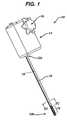
- FIG. 1is a perspective view of one exemplary embodiment of an elongate surgical device
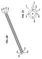
- FIG. 2Ais a perspective view of a distal end of the elongate surgical device of FIG. 1 ;
- FIG. 2Bis a representation of a tensioning element having a plurality of cables
- FIG. 2Cis a cross-sectional view taken along line 2 C- 2 C of the device of FIG. 1 ;
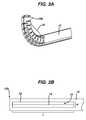
- FIG. 3Ais a perspective view of a distal portion of the elongate surgical device of FIG. 1 in an articulated configuration
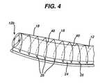
- FIG. 4is a side view of the surgical device of FIG. 1 having a retaining element spiraled around a portion of the device;
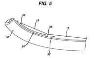
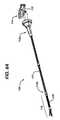
- FIG. 5is a side view of another embodiment of a surgical device having a steering assembly slidably coupled thereto;
- FIG. 6Ais a perspective view of another embodiment of a surgical device having an end effector coupled to a distal end of an elongate shaft;
- FIG. 6Bis a side view of the surgical device of FIG. 6A showing the device is in an articulated configuration
- FIG. 7is a cross-sectional view of an embodiment of a surgical device having a handle with a pulley system for articulating the device.
- the tensioning elementcan move from a slackened state to a tensioned state thereby exerting a pulling force on the distal end of the device, thus causing the distal end to articulate, i.e., move in a direction away from a central axis of the device.
- the deviceincludes at least one channel formed in a wall thereof and extending from the proximal to distal end of the sleeve.
- the channel(s)can define an inner lumen which is configured to slidably receive the tensioning element along the length of the device.
- FIG. 1provides one exemplary embodiment of an articulating device.
- the device 10includes an elongate sleeve 12 having a proximal end 12 a coupled to a handle 14 which is in communication with an actuator 15 .
- the sleeve 12can have virtually any length and/or diameter as required for a given procedure. Additionally, while the sleeve 12 can have a generally circular cross-sectional shape, those skilled in the art will appreciate that virtually any cross-sectional shape is within the spirit and scope of the present disclosure. Additionally, the sleeve 12 can be formed from virtually any material(s) capable of providing a flexibility necessary to navigate a tortuous body lumen.
- Adjacent slits 26can also be radially offset from one another.
- the location, quantity, and shape of each slit 26can vary to obtain the desired flexibility.
- the flexible portion 16can have a smaller diameter as compared to the remainder of the sleeve 12 or the flexible portion 16 can be formed of a more flexible material as compared to the remainder of the sleeve 12 .
- the flexible portion 16can be located at virtually any position along the length of the sleeve and/or the sleeve can include any number and/or length of such flexible portions 16 .
- the elongate sleeve 12can include an inner lumen 20 extending through an outer wall 21 thereby defining a longitudinal axis of the sleeve 12 .
- the inner lumen 20can be configured to allow for delivery of various instruments and/or tools to a surgical site.
- the sleeve 12can be an accessory sleeve having a rail 24 for mating to a second endoscopic device (such as an endoscopic sleeve, not shown).
- various toolscan be delivered adjacent to the working end of the endoscopic device via the inner lumen 20 of the sleeve 12 .
- the elongate sleeve 12can also include one or a plurality of bores or channels 22 a - d formed within the outer wall 21 of the sleeve 12 , and each channel 22 a - d can define an inner lumen extending from the distal end 12 b to the proximal end 12 a of the sleeve 12 .
- the inner lumen of each channel 22 a - dcan be configured to slidably receive a tensioning element, such as a cable 18 a - d , thereby allowing each tensioning element to extend along the entire length of the sleeve 12 .
- each cable 18 a - dcan slide proximally within the corresponding channels 22 a - d while translating the force to the distal end 12 b of the sleeve 12 .
- the channels 22 a - dcan be configured such that during articulation, a maximum amount of force can be to transferred to the distal end of the sleeve 12 thereby enhancing the functionality of the device.
- the tensioning elementincludes four cables 18 a - d extending along the sleeve 12 generally parallel to one another and positioned approximately 90 degrees apart from one another around a circumference of the sleeve 12 .
- applying a proximal force to cables 18 a , 18 c positioned about 180 degrees from one anothercan articulate the sleeve 12 along a first plane of movement (e.g., left and right) and applying a proximal force to a second set of cables 18 b , 18 d positioned about 180 degrees from one another can articulate the sleeve 12 along a second plane of movement (e.g., up and down).
- a tensioning elementhaving any number and/or relative positioning of cables or other wires, cords, etc. are within the spirit and scope of the present disclosure.
- the tensioning element 18can be slidably coupled to the elongate sleeve 12 in various manners.
- the elongate sleeve 12can include various channels 22 a - d formed therein with each channel 22 a - d defining an inner lumen configured to receive a cable 18 a - 18 d of the tensioning element.
- the channels 22 a - dhave a cross-sectional shape substantially similar to a cross-sectional shape of a cable 18 a - 18 d disposed therein thereby facilitating sliding of the cable 18 a - 18 d .
- FIG. 2Bshows a representation of four cables 18 a - d relative to one another when disposed in four corresponding channels 22 a - d of the elongate sleeve 12 (sleeve and channels being hidden from view).
- the distal ends 30 a - d of the cables 18 a - d of the tensioning element 18can be engaged to a desired location along the length of the corresponding channel 22 a - d in virtually any manner known in the art. For example, referring to FIG.
- the ends 30 a - d of the cables 18 a - dcan be pulled into contact with the distal end of the sleeve 12 cause the sleeve 12 to articulate away from the axis of the sleeve 12 .
- the ends 30 a - d of the cables 18 a - dcan be glued, tied, stapled, or otherwise fixedly attached to the desired location along the corresponding channel 22 a - d .
- each cable 18 a - dcan be engaged at distinct locations along the length of the sleeve 12 so as to enable various additional modes of articulation.
- a distal end 30 a of a first cable 18 acan be engaged to a distal-most end of the sleeve 12 and a distal end 30 c of a second cable 18 c can be engaged to the sleeve 12 at a location proximal to the distal-most end of the elongate sleeve 12 .
- a first articulation forcecan be supplied to the first cable 18 a and a second articulation force can be supplied to the second cable 18 c thereby allowing the sleeve 12 to adopt an “S-shaped” configuration.
- the presently disclosed elongate surgical devicecan utilize a tensioning element having any number of cables with distal ends engaged to virtually any location along the length of the sleeve 12 thereby providing a wide range of possible configurations into which the sleeve 12 can be articulated or deformed.
- the various channels 22 a - dcan be configured to allow the cables 18 a - d disposed therein to achieve an enhanced mechanical advantage over a working end of the sleeve 12 .
- the channel 22can include one or a plurality of openings 32 in communication with the inner lumen of the channel 22 .
- the opening 32can be configured so as to allow the tensioning element 18 to exit the channel 22 and thereby move away from a longitudinal axis of the surgical device 10 . For example, looking at FIG.
- the opening(s) 32can be positioned at a distal end of the channel 22 , at a location proximal to the distal end of the channel 22 , at a proximal end of the channel 22 , etc.
- each channel 22can include virtually any number of openings 32 as required to provide the desired articulation.
- the device 10can include a channel having a first opening formed at a location proximal to the distal end of the channel and a second opening located proximal to the first opening.
- the device 10can include only one channel 22 having at least one opening 32 , the device can include more than one channel 22 having at least one opening 32 , or each channel 22 of the device can include at least one opening 32 .
- the retaining element 40is a cable spiraled around a length of the sleeve 12 .
- the retaining element 40can be a wire, suture, thread, sleeve, etc.
- the retaining element 40can extend along any desired length of the sleeve 12 .
- the retaining element 40can be a continuous cable, wire, suture, sleeve, etc., or the retaining element 40 can be discontinuous.
- the retaining element 40can be spiraled around the elongate sleeve 12 of the device 10 .
- each spiral and/or a diameter of each spiralcan be optimized to provide a desired degree of stability and/or rigidity.
- Each spiralcan also be fixedly coupled to a portion of the sleeve 12 to allow each spiral to maintain a desired diameter, and to allow adjacent spirals to vary in diameter.
- a rail 24extends along the shaft 12 of the device 10 and includes a plurality of openings 25 formed therein which are configured and positioned to receive each successive spiral of the retaining element 40 .
- the spiralscan be fixed within each opening using various mating techniques. Alternatively, the spirals can be slidably disposed through the openings.
- the spiralscan also be rigid or flexible, and in some embodiments can have a predetermined shape, e.g., by forming the spirals from a shape memory material or from another material that retains its shape.
- the retaining element 40is spiraled around a length of the shaft 12 and not positioned through such openings 25 .
- FIGS. 6A-6Bprovide another embodiment of a surgical device 100 having an elongate shaft 112 with a proximal end 112 a coupled to a handle element 114 and a distal end 112 b coupled to an end effector 116 .
- the end effector 116can be virtually any such end effector capable of providing a desired therapeutic function.
- the end effectorcan be a surgical stapler and cutting device.
- the device 100can, similar to the embodiments described above, include a tensioning element 18 extending from a proximal handle portion 114 (and actuator 115 ) to a distal end 112 b of the shaft 112 .
- the shaft 112can also include a flexible portion 126 formed at a distal end of the device 100 thereby facilitating articulation at the flexible portion 126 .
- the tensioning element 18can be disposed within a channel extending from the proximal to the distal end of the device 100 and the channel can include an opening configured to allow the element 18 to exit the channel during articulation of the shaft thereby enhancing a mechanical advantage over a distal end of the device.
- the actuator 15can include a first actuation knob 17 configured to apply a force to a first cable by rotating the knob 17 in a first direction (e.g., clockwise), and to apply a force to a second cable by rotating the knob 17 in an opposite direction (e.g., counter-clockwise).
- the first actuation knob 17can thus control articulation along a first plane of movement (e.g., left-right) where the first and second cables extend along opposite sides of the sleeve.
- the actuator 15can also include a second articulation knob 19 configured to apply a force to a third cable by rotating the knob 19 in a first direction (e.g., clockwise), and to apply a force to a fourth cable by rotating the knob 19 in an opposite direction (e.g., counter-clockwise).
- the second articulation knob 19can control articulation along a second plane of movement (e.g., up-down) where the third and fourth cables extend along opposite sides of the sleeve and are radially offset about 90 degrees from the first and second cables.
- FIGS. 6A-6Bprovide another embodiment of a handle 114 and/or actuator 115 which is movably coupled to a proximal end of the device. In use, as shown in FIG.
- a forcecan be supplied to the tensioning element 18 (thereby resulting in articulation) by pivoting the actuator 115 relative to the elongate shaft 112 of the device 100 , e.g., in a direction opposite to a desired direction of articulation.
- a handle and/or actuatorcan be found in Assignee's co-pending U.S. patent application Ser. No. 11/277,323, filed on Mar. 23, 2006, and Assignee's co-pending U.S. patent application Ser. No. 11/762,855, filed on Jun. 14, 2007, the entirety of these disclosures being incorporated herein by reference.
- the methodcan include articulating virtually any type of flexible elongate device configured to travel along a tortuous body lumen to a surgical site.
- the elongate devicecan be an accessory sleeve configured to couple to a second flexible sleeve (e.g., an endoscopic device).
- the flexible elongate devicecan be a surgical instrument having an end effector (e.g., a surgical stapler or clip applier, graspers, cutters, coagulators, etc.) coupled to a distal end thereof.
- the methodcan include delivering the flexible elongate device along a tortuous body to a surgical site.
- the elongate devicecan include an inner lumen defining a longitudinal axis.
- the methodcan also include applying tension to a tensioning element extending through the elongate device thereby articulating the device.
- the devicecan be configured such that a distance between the longitudinal axis of the device and a portion of tensioning element increases during articulation.
- the methodcan include use of an elongate device having a tensioning element with any number of cables.
- the tensioning elementcan include a first cable and a second cable.
- the methodcan include applying tension to the first cable which can move away from the longitudinal axis of the inner lumen of the device in response to such tension.
- the methodcan include application of a second force or tension to the second cable which can also move away from the longitudinal axis of the device in response to articulation.
- the methodcan utilize a surgical device having any number of cables, wires, cords, etc., disposed in any number of channels formed therein.
- any of the channelscan include any number of openings configured to allow the tensioning element to move away from the longitudinal axis of the device during articulation.
- the methodcan include controlling the distance between the longitudinal axis of the inner lumen and the tensioning element by positioning a retaining element around a portion of the elongate device such that the retainer element is configured to engage the tensioning element as the element moves away from the longitudinal axis.
- the methodcan also include sterilizing any component of any embodiment of the device after at least one use.
- the various devices disclosed herein, including portions thereofcan be designed to be disposed of after a single use, or they can be designed to be used multiple times. In either case, the device can be reconditioned for reuse after at least one use. Reconditioning can include any combination of the steps of disassembly of the device, followed by cleaning or replacement of particular pieces, and subsequent reassembly.
- the elongate surgical sleeve of FIG. 1 and the surgical stapling and fastening device shown in FIGS. 6A and 6Bcan be reconditioned after the device has been used in a medical procedure.
- the devicecan be disassembled, and any number of the particular pieces can be selectively replaced or removed in any combination.
- a cartridge disposed within the end effector and containing a plurality of fastenerscan be replaced by adding a new fastener cartridge to the end effector.
- the devicecan be reassembled for subsequent use either at a reconditioning facility, or by a surgical team immediately prior to a surgical procedure.
- reconditioning of a devicecan utilize a variety of techniques for disassembly, cleaning/replacement, and reassembly. Use of such techniques, and the resulting reconditioned device, are all within the scope of the present application.
- the various embodiments of the device described hereinwill be processed before surgery.
- a new or used instrumentis obtained and if necessary cleaned.
- the instrumentcan then be sterilized.
- the instrumentis placed in a closed and sealed container, such as a plastic or TYVEK bag.
- the container and instrumentare then placed in a field of radiation that can penetrate the container, such as gamma radiation, x-rays, or high-energy electrons.
- the radiationkills bacteria on the instrument and in the container.
- the sterilized instrumentcan then be stored in the sterile container.
- the sealed containerkeeps the instrument sterile until it is opened in the medical facility.
Landscapes
- Health & Medical Sciences (AREA)
- Life Sciences & Earth Sciences (AREA)
- Surgery (AREA)
- Animal Behavior & Ethology (AREA)
- Public Health (AREA)
- Engineering & Computer Science (AREA)
- Biomedical Technology (AREA)
- Heart & Thoracic Surgery (AREA)
- Medical Informatics (AREA)
- Molecular Biology (AREA)
- Veterinary Medicine (AREA)
- General Health & Medical Sciences (AREA)
- Nuclear Medicine, Radiotherapy & Molecular Imaging (AREA)
- Pathology (AREA)
- Physics & Mathematics (AREA)
- Biophysics (AREA)
- Optics & Photonics (AREA)
- Radiology & Medical Imaging (AREA)
- Ophthalmology & Optometry (AREA)
- Surgical Instruments (AREA)
Abstract
Description
Claims (20)
Priority Applications (2)
| Application Number | Priority Date | Filing Date | Title |
|---|---|---|---|
| US11/971,410US8287469B2 (en) | 2008-01-09 | 2008-01-09 | Articulating surgical device and method of use |
| PCT/US2008/087340WO2009088690A1 (en) | 2008-01-09 | 2008-12-18 | Articulating surgical device and method of use |
Applications Claiming Priority (1)
| Application Number | Priority Date | Filing Date | Title |
|---|---|---|---|
| US11/971,410US8287469B2 (en) | 2008-01-09 | 2008-01-09 | Articulating surgical device and method of use |
Publications (2)
| Publication Number | Publication Date |
|---|---|
| US20090177041A1 US20090177041A1 (en) | 2009-07-09 |
| US8287469B2true US8287469B2 (en) | 2012-10-16 |
Family
ID=40445858
Family Applications (1)
| Application Number | Title | Priority Date | Filing Date |
|---|---|---|---|
| US11/971,410Expired - Fee RelatedUS8287469B2 (en) | 2008-01-09 | 2008-01-09 | Articulating surgical device and method of use |
Country Status (2)
| Country | Link |
|---|---|
| US (1) | US8287469B2 (en) |
| WO (1) | WO2009088690A1 (en) |
Cited By (23)
| Publication number | Priority date | Publication date | Assignee | Title |
|---|---|---|---|---|
| US8986225B2 (en) | 2012-08-02 | 2015-03-24 | Covidien Lp | Guidewire |
| US9038880B1 (en)* | 2011-04-25 | 2015-05-26 | Cardica, Inc. | Articulated surgical instrument |
| US10092359B2 (en) | 2010-10-11 | 2018-10-09 | Ecole Polytechnique Federale De Lausanne | Mechanical manipulator for surgical instruments |
| US10265129B2 (en) | 2014-02-03 | 2019-04-23 | Distalmotion Sa | Mechanical teleoperated device comprising an interchangeable distal instrument |
| US10325072B2 (en) | 2011-07-27 | 2019-06-18 | Ecole Polytechnique Federale De Lausanne (Epfl) | Mechanical teleoperated device for remote manipulation |
| US10348072B2 (en)* | 2015-05-22 | 2019-07-09 | race result AG | Floor cable channel |
| US10357320B2 (en) | 2014-08-27 | 2019-07-23 | Distalmotion Sa | Surgical system for microsurgical techniques |
| US10363055B2 (en) | 2015-04-09 | 2019-07-30 | Distalmotion Sa | Articulated hand-held instrument |
| US10413374B2 (en) | 2018-02-07 | 2019-09-17 | Distalmotion Sa | Surgical robot systems comprising robotic telemanipulators and integrated laparoscopy |
| US10548680B2 (en) | 2014-12-19 | 2020-02-04 | Distalmotion Sa | Articulated handle for mechanical telemanipulator |
| US10568709B2 (en) | 2015-04-09 | 2020-02-25 | Distalmotion Sa | Mechanical teleoperated device for remote manipulation |
| US10646294B2 (en) | 2014-12-19 | 2020-05-12 | Distalmotion Sa | Reusable surgical instrument for minimally invasive procedures |
| US10786272B2 (en) | 2015-08-28 | 2020-09-29 | Distalmotion Sa | Surgical instrument with increased actuation force |
| US10786271B2 (en) | 2014-04-17 | 2020-09-29 | Stryker Corporation | Surgical tool with selectively bendable shaft that resists buckling |
| US10864049B2 (en) | 2014-12-19 | 2020-12-15 | Distalmotion Sa | Docking system for mechanical telemanipulator |
| US10864052B2 (en) | 2014-12-19 | 2020-12-15 | Distalmotion Sa | Surgical instrument with articulated end-effector |
| US11039820B2 (en) | 2014-12-19 | 2021-06-22 | Distalmotion Sa | Sterile interface for articulated surgical instruments |
| US11058503B2 (en) | 2017-05-11 | 2021-07-13 | Distalmotion Sa | Translational instrument interface for surgical robot and surgical robot systems comprising the same |
| US11446103B2 (en)* | 2012-02-02 | 2022-09-20 | Great Belief International Limited | Instruments for mechanized surgical system |
| US11844585B1 (en) | 2023-02-10 | 2023-12-19 | Distalmotion Sa | Surgical robotics systems and devices having a sterile restart, and methods thereof |
| US12114945B2 (en) | 2021-09-13 | 2024-10-15 | Distalmotion Sa | Instruments for surgical robotic system and interfaces for the same |
| US12376927B2 (en) | 2018-02-07 | 2025-08-05 | Distalmotion Sa | Surgical robot systems comprising robotic telemanipulators and integrated laparoscopy |
| US12402960B2 (en) | 2010-10-11 | 2025-09-02 | Ecole Polytechnique Federale De Lausanne (Epfl) | Mechanical manipulator for surgical instruments |
Families Citing this family (23)
| Publication number | Priority date | Publication date | Assignee | Title |
|---|---|---|---|---|
| US20090182195A1 (en)* | 2008-01-11 | 2009-07-16 | Ethicon Endo-Surgery, Inc. | Endoscopic guide system |
| CA2740867C (en)* | 2008-10-16 | 2018-06-12 | Aptus Endosystems, Inc. | Devices, systems, and methods for endovascular staple and/or prosthesis delivery and implantation |
| US20100125168A1 (en)* | 2008-11-14 | 2010-05-20 | Ethicon Endo-Surgery, Inc. | Methods and devices for endoscope control in a body cavity |
| US7918376B1 (en) | 2009-03-09 | 2011-04-05 | Cardica, Inc. | Articulated surgical instrument |
| US9289208B1 (en) | 2009-05-05 | 2016-03-22 | Cardica, Inc. | Articulation insert for surgical instrument |
| US8096457B1 (en) | 2009-05-05 | 2012-01-17 | Cardica, Inc. | Articulation mechanisms for surgical instrument |
| ES2662543T3 (en) | 2010-01-26 | 2018-04-06 | Artack Medical (2013) Ltd. | Articulated medical instrument |
| WO2012016967A1 (en)* | 2010-08-01 | 2012-02-09 | Seckin Tamer A | Surgical method and apparatus |
| US8849418B2 (en)* | 2011-03-11 | 2014-09-30 | Greatbatch Ltd. | Anchor sleeve for implantable lead |
| US9474527B1 (en) | 2011-04-26 | 2016-10-25 | Bryan D. Knodel | Surgical instrument with discrete articulation |
| US9566048B1 (en) | 2011-04-26 | 2017-02-14 | Cardica, Inc. | Surgical instrument with discrete cammed articulation |
| US8419720B1 (en) | 2012-02-07 | 2013-04-16 | National Advanced Endoscopy Devices, Incorporated | Flexible laparoscopic device |
| IL231054A (en)* | 2014-02-20 | 2015-07-30 | Tzony Siegal | Apparatus for advancement along a predetermined curved trajectory and a method for operation thereof |
| SG11201707305PA (en)* | 2015-03-12 | 2017-10-30 | Univ Keio | Treatment-instrument insertion aid |
| MY195396A (en)* | 2015-03-12 | 2023-01-18 | Univ Keio | Treatment-instrument insertion aid |
| US20160262738A1 (en)* | 2015-03-12 | 2016-09-15 | Nir Altman | Superelastic articulating mechanism |
| CN107771060B (en) | 2015-06-18 | 2021-06-04 | 伊西康有限责任公司 | Dual-articulation drive system structure for articulating surgical instruments |
| US10154841B2 (en)* | 2015-06-18 | 2018-12-18 | Ethicon Llc | Surgical stapling instruments with lockout arrangements for preventing firing system actuation when a cartridge is spent or missing |
| CN210673408U (en)* | 2018-01-03 | 2020-06-05 | 杭州启明医疗器械股份有限公司 | Flexible sheath and flexible interventional valve delivery system |
| WO2022003659A1 (en) | 2020-06-29 | 2022-01-06 | T.A.G. Medical Devices - Agriculture Cooperative Ltd. | Working channel device |
| JP7376612B2 (en)* | 2019-05-24 | 2023-11-08 | ベクトン・ディキンソン・アンド・カンパニー | Articulating reinforcement cannulas, access sets, and methods |
| WO2020237420A1 (en) | 2019-05-24 | 2020-12-03 | Becton, Dickinson And Company | Needle-tract assistant including components and methods thereof |
| WO2024229428A1 (en)* | 2023-05-04 | 2024-11-07 | Boston Scientific Scimed, Inc. | Devices, systems, and methods for articulation and/or retroflexion of a medical device |
Citations (112)
| Publication number | Priority date | Publication date | Assignee | Title |
|---|---|---|---|---|
| US3470876A (en) | 1966-09-28 | 1969-10-07 | John Barchilon | Dirigible catheter |
| US3739770A (en) | 1970-10-09 | 1973-06-19 | Olympus Optical Co | Bendable tube of an endoscope |
| GB2109241A (en) | 1981-09-11 | 1983-06-02 | Fuji Photo Optical Co Ltd | Endoscope together with another medical appliance |
| US4454887A (en) | 1981-04-15 | 1984-06-19 | Krueger Christian | Medical instruments for introduction into the respiratory tract of a patient |
| US4520817A (en) | 1980-02-05 | 1985-06-04 | United States Surgical Corporation | Surgical instruments |
| US4580551A (en) | 1984-11-02 | 1986-04-08 | Warner-Lambert Technologies, Inc. | Flexible plastic tube for endoscopes and the like |
| US5040715A (en) | 1989-05-26 | 1991-08-20 | United States Surgical Corporation | Apparatus and method for placing staples in laparoscopic or endoscopic procedures |
| US5100420A (en) | 1989-07-18 | 1992-03-31 | United States Surgical Corporation | Apparatus and method for applying surgical clips in laparoscopic or endoscopic procedures |
| US5211649A (en) | 1987-02-10 | 1993-05-18 | Vaso Products Australia Pty. Limited | Venous cuff applicator, cartridge and cuff |
| EP0552050A2 (en) | 1992-01-17 | 1993-07-21 | Ethicon, Inc. | Endoscopic surgical system with sensing means |
| EP0552423A2 (en) | 1991-10-18 | 1993-07-28 | United States Surgical Corporation | Self contained gas powered surgical apparatus |
| US5259366A (en) | 1992-11-03 | 1993-11-09 | Boris Reydel | Method of using a catheter-sleeve assembly for an endoscope |
| US5285795A (en)* | 1991-09-12 | 1994-02-15 | Surgical Dynamics, Inc. | Percutaneous discectomy system having a bendable discectomy probe and a steerable cannula |
| GB2272159A (en) | 1992-11-10 | 1994-05-11 | Andreas G Constantinides | Surgical/diagnostic aid |
| US5318013A (en) | 1992-11-06 | 1994-06-07 | Wilk Peter J | Surgical clamping assembly and associated method |
| EP0634144A1 (en) | 1993-07-15 | 1995-01-18 | Ethicon, Inc. | An Endoscopic instrument having a torsionally stiff drive shaft for applying fasteners to tissue |
| US5431322A (en) | 1991-10-18 | 1995-07-11 | United States Surgical Corporation | Self contained gas powered surgical apparatus |
| US5460168A (en) | 1992-12-25 | 1995-10-24 | Olympus Optical Co., Ltd. | Endoscope cover assembly and cover-system endoscope |
| US5482197A (en) | 1991-10-18 | 1996-01-09 | United States Surgical Corporation | Articulating surgical cartridge assembly |
| US5489256A (en) | 1992-09-01 | 1996-02-06 | Adair; Edwin L. | Sterilizable endoscope with separable disposable tube assembly |
| EP0705570A1 (en) | 1994-10-07 | 1996-04-10 | United States Surgical Corporation | Self-contained powered surgical apparatus |
| US5618294A (en)* | 1994-05-24 | 1997-04-08 | Aust & Taylor Medical Corporation | Surgical instrument |
| US5624381A (en) | 1994-08-09 | 1997-04-29 | Kieturakis; Maciej J. | Surgical instrument and method for retraction of an anatomic structure defining an interior lumen |
| US5630782A (en) | 1992-09-01 | 1997-05-20 | Adair; Edwin L. | Sterilizable endoscope with separable auxiliary assembly |
| US5651491A (en) | 1995-10-27 | 1997-07-29 | United States Surgical Corporation | Surgical stapler having interchangeable loading units |
| US5715988A (en) | 1995-08-14 | 1998-02-10 | United States Surgical Corporation | Surgical stapler with lockout mechanism |
| US5749889A (en) | 1996-02-13 | 1998-05-12 | Imagyn Medical, Inc. | Method and apparatus for performing biopsy |
| US5762256A (en) | 1995-08-28 | 1998-06-09 | United States Surgical Corporation | Surgical stapler |
| US5782396A (en) | 1995-08-28 | 1998-07-21 | United States Surgical Corporation | Surgical stapler |
| EP0880338A1 (en) | 1996-02-13 | 1998-12-02 | Imagyn Medical, Inc. | Surgical access device and method of constructing same |
| US5848986A (en) | 1992-08-12 | 1998-12-15 | Vidamed, Inc. | Medical probe with electrode guide for transurethral ablation |
| US5865361A (en) | 1997-09-23 | 1999-02-02 | United States Surgical Corporation | Surgical stapling apparatus |
| US5916147A (en) | 1997-09-22 | 1999-06-29 | Boury; Harb N. | Selectively manipulable catheter |
| US5954259A (en) | 1994-08-05 | 1999-09-21 | United States Surgical Corporation | Self-contained powered surgical apparatus for applying surgical fasteners |
| JP2000033071A (en) | 1998-07-17 | 2000-02-02 | Olympus Optical Co Ltd | Endoscope therapeutic device |
| US6032849A (en) | 1995-08-28 | 2000-03-07 | United States Surgical | Surgical stapler |
| US6066090A (en) | 1997-06-19 | 2000-05-23 | Yoon; Inbae | Branched endoscope system |
| US6071233A (en) | 1997-10-31 | 2000-06-06 | Olympus Optical Co., Ltd. | Endoscope |
| JP2000171730A (en) | 1998-12-08 | 2000-06-23 | Olympus Optical Co Ltd | Battery type portable endoscopic device |
| WO2000048506A1 (en) | 1999-02-15 | 2000-08-24 | Herrmann Ingo F | Deformable fiberscope with a displaceable supplementary device |
| US6109500A (en) | 1996-10-04 | 2000-08-29 | United States Surgical Corporation | Lockout mechanism for a surgical stapler |
| JP2000325303A (en) | 1999-05-17 | 2000-11-28 | Olympus Optical Co Ltd | Endoscopic therapeutic device |
| WO2000072762A1 (en) | 1999-06-02 | 2000-12-07 | Powermed, Inc. | Electromechanical driver for an anastomosis surgical stapler |
| WO2000072765A1 (en) | 1999-06-02 | 2000-12-07 | Powermed, Inc. | An electromechanical driver device for use with anastomosing, stapling, and resecting instruments |
| US6179776B1 (en) | 1999-03-12 | 2001-01-30 | Scimed Life Systems, Inc. | Controllable endoscopic sheath apparatus and related method of use |
| US6264087B1 (en) | 1999-07-12 | 2001-07-24 | Powermed, Inc. | Expanding parallel jaw device for use with an electromechanical driver device |
| US6328730B1 (en) | 1999-03-26 | 2001-12-11 | William W. Harkrider, Jr. | Endoluminal multi-luminal surgical sheath and method |
| US6352503B1 (en) | 1998-07-17 | 2002-03-05 | Olympus Optical Co., Ltd. | Endoscopic surgery apparatus |
| US20020049454A1 (en) | 1999-06-02 | 2002-04-25 | Whitman Michael P. | Electro-mechanical surgical device |
| JP2002143078A (en) | 2000-11-08 | 2002-05-21 | Olympus Optical Co Ltd | Outside tube for endoscope |
| WO2002043571A2 (en) | 2000-11-28 | 2002-06-06 | Power Medical Interventions, Inc. | Electro-mechanical surgical device |
| US20020120253A1 (en) | 2001-02-26 | 2002-08-29 | Asahi Kogaku Kogyo Kabushiki Kaisha | Treatment tools for endoscope |
| US6468203B2 (en) | 2000-04-03 | 2002-10-22 | Neoguide Systems, Inc. | Steerable endoscope and improved method of insertion |
| US6522101B2 (en) | 1999-12-10 | 2003-02-18 | Stryker Corporation | Rechargeable battery with memory that contains charging sequence data |
| EP1284120A1 (en) | 2001-08-09 | 2003-02-19 | Ingo F. Prof. Dr. Herrmann | Disposable endoscope sheath |
| WO2003015604A2 (en) | 2001-08-16 | 2003-02-27 | Is, Llc | Apparatus for delivering instrument over endoscope |
| WO2003077769A1 (en) | 2002-03-15 | 2003-09-25 | Power Medical Interventions, Inc. | Drive shaft for an electro-mechanical surgical device |
| US20030199736A1 (en)* | 2000-07-18 | 2003-10-23 | Christopher Kent L. | Endoscope with a removable suction tube |
| WO2004021868A2 (en) | 2002-09-06 | 2004-03-18 | C.R. Bard, Inc. | External endoscopic accessory control system |
| EP1400214A2 (en) | 2002-09-18 | 2004-03-24 | Ethicon Endo-Surgery | Endoscopic ablation system with a distally mounted image sensor |
| EP1402837A1 (en) | 2002-09-18 | 2004-03-31 | Ethicon Endo-Surgery, Inc. | Endoscopic ablation system with a plurality of electrodes |
| US6716233B1 (en) | 1999-06-02 | 2004-04-06 | Power Medical Interventions, Inc. | Electromechanical driver and remote surgical instrument attachment having computer assisted control capabilities |
| WO2004034875A2 (en) | 2002-10-15 | 2004-04-29 | Dusa Pharmaceuticals, Inc. | Medical device sheath apparatus and method |
| US6740030B2 (en) | 2002-01-04 | 2004-05-25 | Vision Sciences, Inc. | Endoscope assemblies having working channels with reduced bending and stretching resistance |
| WO2004047626A1 (en) | 2002-11-22 | 2004-06-10 | Jiang, Shoumei | Endoscope assembly with disposable sheath |
| WO2004052426A2 (en) | 2002-12-05 | 2004-06-24 | Vision-Sciences, Inc. | Endoscopic sheath assemblies having longitudinal expansion inhibiting mechanisms |
| US20040133075A1 (en) | 2002-08-06 | 2004-07-08 | Nobuyuki Motoki | Endoscope apparatus |
| US6786864B2 (en) | 2001-02-06 | 2004-09-07 | Olympus Corporation | Endoscopic system and method for positioning an indwelling tube |
| US6790173B2 (en) | 2002-06-13 | 2004-09-14 | Usgi Medical, Inc. | Shape lockable apparatus and method for advancing an instrument through unsupported anatomy |
| US6793621B2 (en) | 2001-03-08 | 2004-09-21 | Atropos Limited | Colonic overtube |
| EP1459695A1 (en) | 2003-03-21 | 2004-09-22 | Ethicon Endo-Surgery, Inc. | Medical device with improved wall construction |
| US20040215058A1 (en) | 2002-09-06 | 2004-10-28 | Zirps Christopher T | Endoscopic accessory mounting adaptor |
| US20040230096A1 (en) | 2003-05-16 | 2004-11-18 | David Stefanchik | Method of guiding medical devices |
| US20040230097A1 (en) | 2003-05-16 | 2004-11-18 | David Stefanchik | Endcap for use with an endoscope |
| WO2004103157A2 (en) | 2003-05-15 | 2004-12-02 | Lsi Solutions, Inc. | System for endoscopic suturing |
| WO2004105593A1 (en) | 2003-05-29 | 2004-12-09 | Kiyoteru Shima | External forceps channel device for endoscope |
| US6830545B2 (en) | 2002-05-13 | 2004-12-14 | Everest Vit | Tube gripper integral with controller for endoscope of borescope |
| US20050049460A1 (en) | 2003-02-11 | 2005-03-03 | Olympus Corporation | Over-tube, method of manufacturing over-tube, method of disposing over-tube, and method of treatment in abdominal cavity |
| US20050080451A1 (en) | 2003-10-10 | 2005-04-14 | Scimed Life Systems, Inc. | Device with deflectable distal end and related methods of use |
| JP2005131211A (en) | 2003-10-31 | 2005-05-26 | Olympus Corp | Externally mounted channel for endoscope |
| JP2005131173A (en) | 2003-10-31 | 2005-05-26 | Olympus Corp | Externally mounted channel for endoscope |
| JP2005131163A (en) | 2003-10-31 | 2005-05-26 | Olympus Corp | External channel for endoscope |
| JP2005131164A (en) | 2003-10-31 | 2005-05-26 | Olympus Corp | External channel for endoscope |
| JP2005131212A (en) | 2003-10-31 | 2005-05-26 | Olympus Corp | External channel for endoscope and endoscope device |
| EP1535565A1 (en) | 2003-11-27 | 2005-06-01 | Olympus Corporation | Insertion auxiliary implement for an endoscope |
| US20050119524A1 (en) | 2002-08-07 | 2005-06-02 | Olympus Optical Co., Ltd. | Endoscopic treatment system |
| JP2005137423A (en) | 2003-11-04 | 2005-06-02 | Olympus Corp | External channel for endoscope and branch member for external channel |
| US20050124855A1 (en) | 2000-04-03 | 2005-06-09 | Ross Jaffe | Endoscope having a guide tube |
| US20050131278A1 (en) | 2003-12-16 | 2005-06-16 | Olympus Winter & Ibe Gmbh | Endoscope |
| US20050137455A1 (en) | 2002-06-13 | 2005-06-23 | Usgi Medical Corp. | Shape lockable apparatus and method for advancing an instrument through unsupported anatomy |
| US20050149067A1 (en) | 2002-01-30 | 2005-07-07 | Olympus Corporation | Endoscopic suturing system |
| US20050154258A1 (en) | 2000-04-03 | 2005-07-14 | Tartaglia Joseph M. | Endoscope with adjacently positioned guiding apparatus |
| US20050165419A1 (en) | 2001-02-02 | 2005-07-28 | Sauer Jude S. | System for endoscopic suturing |
| US20050177181A1 (en) | 2002-11-01 | 2005-08-11 | Jonathan Kagan | Devices and methods for treating morbid obesity |
| US20050222495A1 (en) | 2004-04-02 | 2005-10-06 | Olympus Corporation | Medical system with over-tube |
| US20050234297A1 (en) | 2004-04-15 | 2005-10-20 | Wilson-Cook Medical, Inc. | Endoscopic surgical access devices and methods of articulating an external accessory channel |
| JP2005307143A (en) | 2003-06-30 | 2005-11-04 | Bridgestone Corp | Rigid polyurethane foam |
| US20050256374A1 (en) | 2004-05-14 | 2005-11-17 | Ethicon Endo-Surgery, Inc. | Medical instrument having a guidewire and an add-to catheter |
| US20050272977A1 (en) | 2004-04-14 | 2005-12-08 | Usgi Medical Inc. | Methods and apparatus for performing endoluminal procedures |
| US20060020247A1 (en) | 2002-11-01 | 2006-01-26 | Jonathan Kagan | Devices and methods for attaching an endolumenal gastrointestinal implant |
| US7029435B2 (en) | 2003-10-16 | 2006-04-18 | Granit Medical Innovation, Llc | Endoscope having multiple working segments |
| WO2004096015A3 (en) | 2003-04-25 | 2006-04-20 | Applied Med Resources | Steerable kink-resistant sheath |
| US20060259010A1 (en) | 2005-05-13 | 2006-11-16 | David Stefanchik | Feeding tube |
| US20060258904A1 (en) | 2005-05-13 | 2006-11-16 | David Stefanchik | Feeding tube and track |
| US20060258903A1 (en) | 2005-05-13 | 2006-11-16 | David Stefanchik | Method of inserting a feeding tube |
| US20070197996A1 (en)* | 2002-06-04 | 2007-08-23 | Daniel Kraft | Device and method for rapid aspiration and collection of body tissue from within an enclosed body space |
| US20070208364A1 (en) | 2006-03-02 | 2007-09-06 | Kms Development, Llc | Variably flexible insertion device and method for variably flexing an insertion device |
| US20070208224A1 (en) | 2006-03-06 | 2007-09-06 | Boston Scientific Scimed, Inc. | Variable stiffness medical device shaft |
| US20070225562A1 (en) | 2006-03-23 | 2007-09-27 | Ethicon Endo-Surgery, Inc. | Articulating endoscopic accessory channel |
| US20070221700A1 (en) | 2006-03-23 | 2007-09-27 | Ethicon Endo-Surgery, Inc. | Methods and devices for controlling articulation |
| US20080183035A1 (en) | 2007-01-26 | 2008-07-31 | Ethicon Endo-Surgery, Inc. | Endoscopic Accessory Control Mechanism |
| EP1607050B1 (en) | 2004-06-14 | 2009-12-02 | Ethicon Endo-Surgery, Inc. | Clip ejector for endoscopic clip applier |
Family Cites Families (1)
| Publication number | Priority date | Publication date | Assignee | Title |
|---|---|---|---|---|
| AU7255896A (en)* | 1995-10-06 | 1997-04-28 | Brian S. Kelleher | Steerable, flexible forceps device |
- 2008
- 2008-01-09USUS11/971,410patent/US8287469B2/ennot_activeExpired - Fee Related
- 2008-12-18WOPCT/US2008/087340patent/WO2009088690A1/enactiveApplication Filing
Patent Citations (145)
| Publication number | Priority date | Publication date | Assignee | Title |
|---|---|---|---|---|
| US3470876A (en) | 1966-09-28 | 1969-10-07 | John Barchilon | Dirigible catheter |
| US3739770A (en) | 1970-10-09 | 1973-06-19 | Olympus Optical Co | Bendable tube of an endoscope |
| US4520817A (en) | 1980-02-05 | 1985-06-04 | United States Surgical Corporation | Surgical instruments |
| US4454887A (en) | 1981-04-15 | 1984-06-19 | Krueger Christian | Medical instruments for introduction into the respiratory tract of a patient |
| GB2109241A (en) | 1981-09-11 | 1983-06-02 | Fuji Photo Optical Co Ltd | Endoscope together with another medical appliance |
| US4580551A (en) | 1984-11-02 | 1986-04-08 | Warner-Lambert Technologies, Inc. | Flexible plastic tube for endoscopes and the like |
| US5211649A (en) | 1987-02-10 | 1993-05-18 | Vaso Products Australia Pty. Limited | Venous cuff applicator, cartridge and cuff |
| US5040715A (en) | 1989-05-26 | 1991-08-20 | United States Surgical Corporation | Apparatus and method for placing staples in laparoscopic or endoscopic procedures |
| US5040715B1 (en) | 1989-05-26 | 1994-04-05 | United States Surgical Corp | Apparatus and method for placing staples in laparoscopic or endoscopic procedures |
| US5100420A (en) | 1989-07-18 | 1992-03-31 | United States Surgical Corporation | Apparatus and method for applying surgical clips in laparoscopic or endoscopic procedures |
| US5285795A (en)* | 1991-09-12 | 1994-02-15 | Surgical Dynamics, Inc. | Percutaneous discectomy system having a bendable discectomy probe and a steerable cannula |
| US5431322A (en) | 1991-10-18 | 1995-07-11 | United States Surgical Corporation | Self contained gas powered surgical apparatus |
| EP0552423A2 (en) | 1991-10-18 | 1993-07-28 | United States Surgical Corporation | Self contained gas powered surgical apparatus |
| US5482197A (en) | 1991-10-18 | 1996-01-09 | United States Surgical Corporation | Articulating surgical cartridge assembly |
| US5518163A (en) | 1992-01-17 | 1996-05-21 | Ethicon, Inc. | Endoscopic surgical system with sensing means |
| US5667517A (en) | 1992-01-17 | 1997-09-16 | Ethicon, Inc. | Endoscopic surgical system with sensing means |
| EP0552050A2 (en) | 1992-01-17 | 1993-07-21 | Ethicon, Inc. | Endoscopic surgical system with sensing means |
| US5383880A (en) | 1992-01-17 | 1995-01-24 | Ethicon, Inc. | Endoscopic surgical system with sensing means |
| US5518164A (en) | 1992-01-17 | 1996-05-21 | Ethicon, Inc. | Endoscopic surgical system with sensing means |
| US5433721A (en) | 1992-01-17 | 1995-07-18 | Ethicon, Inc. | Endoscopic instrument having a torsionally stiff drive shaft for applying fasteners to tissue |
| US5848986A (en) | 1992-08-12 | 1998-12-15 | Vidamed, Inc. | Medical probe with electrode guide for transurethral ablation |
| US5489256A (en) | 1992-09-01 | 1996-02-06 | Adair; Edwin L. | Sterilizable endoscope with separable disposable tube assembly |
| US5630782A (en) | 1992-09-01 | 1997-05-20 | Adair; Edwin L. | Sterilizable endoscope with separable auxiliary assembly |
| US5259366A (en) | 1992-11-03 | 1993-11-09 | Boris Reydel | Method of using a catheter-sleeve assembly for an endoscope |
| US5318013A (en) | 1992-11-06 | 1994-06-07 | Wilk Peter J | Surgical clamping assembly and associated method |
| GB2272159A (en) | 1992-11-10 | 1994-05-11 | Andreas G Constantinides | Surgical/diagnostic aid |
| US5460168A (en) | 1992-12-25 | 1995-10-24 | Olympus Optical Co., Ltd. | Endoscope cover assembly and cover-system endoscope |
| EP0634144A1 (en) | 1993-07-15 | 1995-01-18 | Ethicon, Inc. | An Endoscopic instrument having a torsionally stiff drive shaft for applying fasteners to tissue |
| US5618294A (en)* | 1994-05-24 | 1997-04-08 | Aust & Taylor Medical Corporation | Surgical instrument |
| US5954259A (en) | 1994-08-05 | 1999-09-21 | United States Surgical Corporation | Self-contained powered surgical apparatus for applying surgical fasteners |
| US5779130A (en) | 1994-08-05 | 1998-07-14 | United States Surgical Corporation | Self-contained powered surgical apparatus |
| US5624381A (en) | 1994-08-09 | 1997-04-29 | Kieturakis; Maciej J. | Surgical instrument and method for retraction of an anatomic structure defining an interior lumen |
| EP0705570A1 (en) | 1994-10-07 | 1996-04-10 | United States Surgical Corporation | Self-contained powered surgical apparatus |
| EP1426012A1 (en) | 1994-10-07 | 2004-06-09 | United States Surgical Corporation | Self-contained powered surgical apparatus |
| US5715988A (en) | 1995-08-14 | 1998-02-10 | United States Surgical Corporation | Surgical stapler with lockout mechanism |
| US5762256A (en) | 1995-08-28 | 1998-06-09 | United States Surgical Corporation | Surgical stapler |
| US5782396A (en) | 1995-08-28 | 1998-07-21 | United States Surgical Corporation | Surgical stapler |
| US6032849A (en) | 1995-08-28 | 2000-03-07 | United States Surgical | Surgical stapler |
| US5651491A (en) | 1995-10-27 | 1997-07-29 | United States Surgical Corporation | Surgical stapler having interchangeable loading units |
| EP0880338A1 (en) | 1996-02-13 | 1998-12-02 | Imagyn Medical, Inc. | Surgical access device and method of constructing same |
| US5749889A (en) | 1996-02-13 | 1998-05-12 | Imagyn Medical, Inc. | Method and apparatus for performing biopsy |
| US6109500A (en) | 1996-10-04 | 2000-08-29 | United States Surgical Corporation | Lockout mechanism for a surgical stapler |
| US6066090A (en) | 1997-06-19 | 2000-05-23 | Yoon; Inbae | Branched endoscope system |
| US5916147A (en) | 1997-09-22 | 1999-06-29 | Boury; Harb N. | Selectively manipulable catheter |
| US5865361A (en) | 1997-09-23 | 1999-02-02 | United States Surgical Corporation | Surgical stapling apparatus |
| US6071233A (en) | 1997-10-31 | 2000-06-06 | Olympus Optical Co., Ltd. | Endoscope |
| JP2000033071A (en) | 1998-07-17 | 2000-02-02 | Olympus Optical Co Ltd | Endoscope therapeutic device |
| US6352503B1 (en) | 1998-07-17 | 2002-03-05 | Olympus Optical Co., Ltd. | Endoscopic surgery apparatus |
| JP2000171730A (en) | 1998-12-08 | 2000-06-23 | Olympus Optical Co Ltd | Battery type portable endoscopic device |
| WO2000048506A1 (en) | 1999-02-15 | 2000-08-24 | Herrmann Ingo F | Deformable fiberscope with a displaceable supplementary device |
| US6878106B1 (en) | 1999-02-15 | 2005-04-12 | Ingo F. Herrmann | Deformable fiberscope with a displaceable supplementary device |
| US7070559B2 (en) | 1999-03-12 | 2006-07-04 | Scimed Life Systems, Inc. | Controllable endoscopic sheath apparatus and related method of use |
| US6761685B2 (en) | 1999-03-12 | 2004-07-13 | Scimed Life Systems, Inc. | Controllable endoscopic sheath apparatus and related method of use |
| US6179776B1 (en) | 1999-03-12 | 2001-01-30 | Scimed Life Systems, Inc. | Controllable endoscopic sheath apparatus and related method of use |
| US6328730B1 (en) | 1999-03-26 | 2001-12-11 | William W. Harkrider, Jr. | Endoluminal multi-luminal surgical sheath and method |
| JP2000325303A (en) | 1999-05-17 | 2000-11-28 | Olympus Optical Co Ltd | Endoscopic therapeutic device |
| US6443973B1 (en) | 1999-06-02 | 2002-09-03 | Power Medical Interventions, Inc. | Electromechanical driver device for use with anastomosing, stapling, and resecting instruments |
| US20020049454A1 (en) | 1999-06-02 | 2002-04-25 | Whitman Michael P. | Electro-mechanical surgical device |
| US6846307B2 (en) | 1999-06-02 | 2005-01-25 | Power Medical Interventions, Inc. | Electro-mechanical surgical device |
| US6846309B2 (en) | 1999-06-02 | 2005-01-25 | Power Medical Interventions, Inc. | Electro-mechanical surgical device |
| WO2000072765A1 (en) | 1999-06-02 | 2000-12-07 | Powermed, Inc. | An electromechanical driver device for use with anastomosing, stapling, and resecting instruments |
| US6846308B2 (en) | 1999-06-02 | 2005-01-25 | Power Medical Interventions, Inc. | Electro-mechanical surgical device |
| WO2003000138A2 (en) | 1999-06-02 | 2003-01-03 | Power Medical Interventions, Inc. | Electro-mechanical surgical device with data memory unit |
| US6793652B1 (en) | 1999-06-02 | 2004-09-21 | Power Medical Interventions, Inc. | Electro-mechanical surgical device |
| US6315184B1 (en) | 1999-06-02 | 2001-11-13 | Powermed, Inc. | Stapling device for use with an electromechanical driver device for use with anastomosing, stapling, and resecting instruments |
| WO2000072762A1 (en) | 1999-06-02 | 2000-12-07 | Powermed, Inc. | Electromechanical driver for an anastomosis surgical stapler |
| US6716233B1 (en) | 1999-06-02 | 2004-04-06 | Power Medical Interventions, Inc. | Electromechanical driver and remote surgical instrument attachment having computer assisted control capabilities |
| US6264087B1 (en) | 1999-07-12 | 2001-07-24 | Powermed, Inc. | Expanding parallel jaw device for use with an electromechanical driver device |
| US6522101B2 (en) | 1999-12-10 | 2003-02-18 | Stryker Corporation | Rechargeable battery with memory that contains charging sequence data |
| US6984203B2 (en) | 2000-04-03 | 2006-01-10 | Neoguide Systems, Inc. | Endoscope with adjacently positioned guiding apparatus |
| US6468203B2 (en) | 2000-04-03 | 2002-10-22 | Neoguide Systems, Inc. | Steerable endoscope and improved method of insertion |
| US20050124855A1 (en) | 2000-04-03 | 2005-06-09 | Ross Jaffe | Endoscope having a guide tube |
| US20050154258A1 (en) | 2000-04-03 | 2005-07-14 | Tartaglia Joseph M. | Endoscope with adjacently positioned guiding apparatus |
| US20060015009A1 (en) | 2000-04-03 | 2006-01-19 | Ross Jaffe | Endoscope having a guide tube |
| US20030199736A1 (en)* | 2000-07-18 | 2003-10-23 | Christopher Kent L. | Endoscope with a removable suction tube |
| JP2002143078A (en) | 2000-11-08 | 2002-05-21 | Olympus Optical Co Ltd | Outside tube for endoscope |
| WO2002043571A2 (en) | 2000-11-28 | 2002-06-06 | Power Medical Interventions, Inc. | Electro-mechanical surgical device |
| US20050165419A1 (en) | 2001-02-02 | 2005-07-28 | Sauer Jude S. | System for endoscopic suturing |
| US6997931B2 (en) | 2001-02-02 | 2006-02-14 | Lsi Solutions, Inc. | System for endoscopic suturing |
| US6786864B2 (en) | 2001-02-06 | 2004-09-07 | Olympus Corporation | Endoscopic system and method for positioning an indwelling tube |
| US20020120253A1 (en) | 2001-02-26 | 2002-08-29 | Asahi Kogaku Kogyo Kabushiki Kaisha | Treatment tools for endoscope |
| US6793621B2 (en) | 2001-03-08 | 2004-09-21 | Atropos Limited | Colonic overtube |
| EP1284120A1 (en) | 2001-08-09 | 2003-02-19 | Ingo F. Prof. Dr. Herrmann | Disposable endoscope sheath |
| US20030195387A1 (en) | 2001-08-16 | 2003-10-16 | Syntheon, Llc | Methods and appartus for delivering a medical instrument over an endoscope while the endoscope is in a body lumen |
| US6569085B2 (en) | 2001-08-16 | 2003-05-27 | Syntheon, Llc | Methods and apparatus for delivering a medical instrument over an endoscope while the endoscope is in a body lumen |
| WO2003015604A2 (en) | 2001-08-16 | 2003-02-27 | Is, Llc | Apparatus for delivering instrument over endoscope |
| US7056284B2 (en) | 2002-01-04 | 2006-06-06 | Vision Sciences, Inc. | Endoscope assemblies having working channels with reduced bending and stretching resistance |
| US6740030B2 (en) | 2002-01-04 | 2004-05-25 | Vision Sciences, Inc. | Endoscope assemblies having working channels with reduced bending and stretching resistance |
| US20060079735A1 (en) | 2002-01-04 | 2006-04-13 | Stephen Martone | Endoscope assemblies having working channels with reduced bending and stretching resistance |
| US20050149067A1 (en) | 2002-01-30 | 2005-07-07 | Olympus Corporation | Endoscopic suturing system |
| WO2003077769A1 (en) | 2002-03-15 | 2003-09-25 | Power Medical Interventions, Inc. | Drive shaft for an electro-mechanical surgical device |
| US6830545B2 (en) | 2002-05-13 | 2004-12-14 | Everest Vit | Tube gripper integral with controller for endoscope of borescope |
| US20070197996A1 (en)* | 2002-06-04 | 2007-08-23 | Daniel Kraft | Device and method for rapid aspiration and collection of body tissue from within an enclosed body space |
| US20050137454A1 (en) | 2002-06-13 | 2005-06-23 | Usgi Medical Corp. | Shape lockable apparatus and method for advancing an instrument through unsupported anatomy |
| US20050137455A1 (en) | 2002-06-13 | 2005-06-23 | Usgi Medical Corp. | Shape lockable apparatus and method for advancing an instrument through unsupported anatomy |
| US6790173B2 (en) | 2002-06-13 | 2004-09-14 | Usgi Medical, Inc. | Shape lockable apparatus and method for advancing an instrument through unsupported anatomy |
| US20040133075A1 (en) | 2002-08-06 | 2004-07-08 | Nobuyuki Motoki | Endoscope apparatus |
| US20050119524A1 (en) | 2002-08-07 | 2005-06-02 | Olympus Optical Co., Ltd. | Endoscopic treatment system |
| WO2004021868A2 (en) | 2002-09-06 | 2004-03-18 | C.R. Bard, Inc. | External endoscopic accessory control system |
| US20040215058A1 (en) | 2002-09-06 | 2004-10-28 | Zirps Christopher T | Endoscopic accessory mounting adaptor |
| EP1400214A2 (en) | 2002-09-18 | 2004-03-24 | Ethicon Endo-Surgery | Endoscopic ablation system with a distally mounted image sensor |
| EP1402837A1 (en) | 2002-09-18 | 2004-03-31 | Ethicon Endo-Surgery, Inc. | Endoscopic ablation system with a plurality of electrodes |
| WO2004034875A2 (en) | 2002-10-15 | 2004-04-29 | Dusa Pharmaceuticals, Inc. | Medical device sheath apparatus and method |
| US20060020247A1 (en) | 2002-11-01 | 2006-01-26 | Jonathan Kagan | Devices and methods for attaching an endolumenal gastrointestinal implant |
| US20050177181A1 (en) | 2002-11-01 | 2005-08-11 | Jonathan Kagan | Devices and methods for treating morbid obesity |
| WO2004047626A1 (en) | 2002-11-22 | 2004-06-10 | Jiang, Shoumei | Endoscope assembly with disposable sheath |
| WO2004052426A2 (en) | 2002-12-05 | 2004-06-24 | Vision-Sciences, Inc. | Endoscopic sheath assemblies having longitudinal expansion inhibiting mechanisms |
| US20050049460A1 (en) | 2003-02-11 | 2005-03-03 | Olympus Corporation | Over-tube, method of manufacturing over-tube, method of disposing over-tube, and method of treatment in abdominal cavity |
| EP1593337A1 (en) | 2003-02-11 | 2005-11-09 | Olympus Corporation | Overtube, producing method and placing method of the same, and method of treating intra-abdominal cavity |
| EP1459695A1 (en) | 2003-03-21 | 2004-09-22 | Ethicon Endo-Surgery, Inc. | Medical device with improved wall construction |
| WO2004096015A3 (en) | 2003-04-25 | 2006-04-20 | Applied Med Resources | Steerable kink-resistant sheath |
| WO2004103157A2 (en) | 2003-05-15 | 2004-12-02 | Lsi Solutions, Inc. | System for endoscopic suturing |
| US20040230095A1 (en) | 2003-05-16 | 2004-11-18 | David Stefanchik | Medical apparatus for use with an endoscope |
| US20040230097A1 (en) | 2003-05-16 | 2004-11-18 | David Stefanchik | Endcap for use with an endoscope |
| EP1477104B1 (en) | 2003-05-16 | 2009-01-14 | Ethicon Endo-Surgery | Medical apparatus for use with an endoscope |
| US20040230096A1 (en) | 2003-05-16 | 2004-11-18 | David Stefanchik | Method of guiding medical devices |
| WO2004105593A1 (en) | 2003-05-29 | 2004-12-09 | Kiyoteru Shima | External forceps channel device for endoscope |
| US20070173687A1 (en) | 2003-05-29 | 2007-07-26 | Kiyoteru Shima | External forceps channel device for endoscope |
| JP2005307143A (en) | 2003-06-30 | 2005-11-04 | Bridgestone Corp | Rigid polyurethane foam |
| US20050080451A1 (en) | 2003-10-10 | 2005-04-14 | Scimed Life Systems, Inc. | Device with deflectable distal end and related methods of use |
| US7029435B2 (en) | 2003-10-16 | 2006-04-18 | Granit Medical Innovation, Llc | Endoscope having multiple working segments |
| JP2005131163A (en) | 2003-10-31 | 2005-05-26 | Olympus Corp | External channel for endoscope |
| JP2005131212A (en) | 2003-10-31 | 2005-05-26 | Olympus Corp | External channel for endoscope and endoscope device |
| JP2005131164A (en) | 2003-10-31 | 2005-05-26 | Olympus Corp | External channel for endoscope |
| JP2005131173A (en) | 2003-10-31 | 2005-05-26 | Olympus Corp | Externally mounted channel for endoscope |
| JP2005131211A (en) | 2003-10-31 | 2005-05-26 | Olympus Corp | Externally mounted channel for endoscope |
| JP2005137423A (en) | 2003-11-04 | 2005-06-02 | Olympus Corp | External channel for endoscope and branch member for external channel |
| US20050119525A1 (en) | 2003-11-27 | 2005-06-02 | Olympus Corporation | Insertion auxiliary implement |
| EP1535565A1 (en) | 2003-11-27 | 2005-06-01 | Olympus Corporation | Insertion auxiliary implement for an endoscope |
| JP2005152416A (en) | 2003-11-27 | 2005-06-16 | Olympus Corp | Insertion auxiliary implement |
| US20050131278A1 (en) | 2003-12-16 | 2005-06-16 | Olympus Winter & Ibe Gmbh | Endoscope |
| US20050222495A1 (en) | 2004-04-02 | 2005-10-06 | Olympus Corporation | Medical system with over-tube |
| EP1582138B1 (en) | 2004-04-02 | 2008-09-10 | Olympus Corporation | Medical system with over-tube |
| US20050272977A1 (en) | 2004-04-14 | 2005-12-08 | Usgi Medical Inc. | Methods and apparatus for performing endoluminal procedures |
| US20050234297A1 (en) | 2004-04-15 | 2005-10-20 | Wilson-Cook Medical, Inc. | Endoscopic surgical access devices and methods of articulating an external accessory channel |
| US20050256374A1 (en) | 2004-05-14 | 2005-11-17 | Ethicon Endo-Surgery, Inc. | Medical instrument having a guidewire and an add-to catheter |
| EP1607050B1 (en) | 2004-06-14 | 2009-12-02 | Ethicon Endo-Surgery, Inc. | Clip ejector for endoscopic clip applier |
| US20060258903A1 (en) | 2005-05-13 | 2006-11-16 | David Stefanchik | Method of inserting a feeding tube |
| US20060258904A1 (en) | 2005-05-13 | 2006-11-16 | David Stefanchik | Feeding tube and track |
| US20060259010A1 (en) | 2005-05-13 | 2006-11-16 | David Stefanchik | Feeding tube |
| US20070208364A1 (en) | 2006-03-02 | 2007-09-06 | Kms Development, Llc | Variably flexible insertion device and method for variably flexing an insertion device |
| US20070208224A1 (en) | 2006-03-06 | 2007-09-06 | Boston Scientific Scimed, Inc. | Variable stiffness medical device shaft |
| US20070225562A1 (en) | 2006-03-23 | 2007-09-27 | Ethicon Endo-Surgery, Inc. | Articulating endoscopic accessory channel |
| US20070221700A1 (en) | 2006-03-23 | 2007-09-27 | Ethicon Endo-Surgery, Inc. | Methods and devices for controlling articulation |
| US20080183035A1 (en) | 2007-01-26 | 2008-07-31 | Ethicon Endo-Surgery, Inc. | Endoscopic Accessory Control Mechanism |
Non-Patent Citations (2)
| Title |
|---|
| International Preliminary Report on Patentability Jul. 13, 2010 for Application No. PCT/US08/087340 (7 Pages). |
| International Search Report, from PCT/US08/087340, mailed Apr. 6, 2009. |
Cited By (43)
| Publication number | Priority date | Publication date | Assignee | Title |
|---|---|---|---|---|
| US10092359B2 (en) | 2010-10-11 | 2018-10-09 | Ecole Polytechnique Federale De Lausanne | Mechanical manipulator for surgical instruments |
| US11076922B2 (en) | 2010-10-11 | 2021-08-03 | Ecole Polytechnique Federale De Lausanne (Epfl) | Mechanical manipulator for surgical instruments |
| US12402960B2 (en) | 2010-10-11 | 2025-09-02 | Ecole Polytechnique Federale De Lausanne (Epfl) | Mechanical manipulator for surgical instruments |
| US9038880B1 (en)* | 2011-04-25 | 2015-05-26 | Cardica, Inc. | Articulated surgical instrument |
| US10510447B2 (en) | 2011-07-27 | 2019-12-17 | Ecole Polytechnique Federale De Lausanne (Epfl) | Surgical teleoperated device for remote manipulation |
| US10325072B2 (en) | 2011-07-27 | 2019-06-18 | Ecole Polytechnique Federale De Lausanne (Epfl) | Mechanical teleoperated device for remote manipulation |
| US11200980B2 (en) | 2011-07-27 | 2021-12-14 | Ecole Polytechnique Federale De Lausanne (Epfl) | Surgical teleoperated device for remote manipulation |
| US11446103B2 (en)* | 2012-02-02 | 2022-09-20 | Great Belief International Limited | Instruments for mechanized surgical system |
| US8986225B2 (en) | 2012-08-02 | 2015-03-24 | Covidien Lp | Guidewire |
| US10265129B2 (en) | 2014-02-03 | 2019-04-23 | Distalmotion Sa | Mechanical teleoperated device comprising an interchangeable distal instrument |
| US12329481B2 (en) | 2014-02-03 | 2025-06-17 | Distalmotion Sa | Mechanical teleoperated device comprising an interchangeable distal instrument |
| US11793536B2 (en) | 2014-04-17 | 2023-10-24 | Stryker Corporation | Surgical tool having cables for selectively steering and locking a shaft in a bend |
| US10786271B2 (en) | 2014-04-17 | 2020-09-29 | Stryker Corporation | Surgical tool with selectively bendable shaft that resists buckling |
| US10357320B2 (en) | 2014-08-27 | 2019-07-23 | Distalmotion Sa | Surgical system for microsurgical techniques |
| US10548680B2 (en) | 2014-12-19 | 2020-02-04 | Distalmotion Sa | Articulated handle for mechanical telemanipulator |
| US12262969B2 (en) | 2014-12-19 | 2025-04-01 | Distalmotion Sa | Reusable surgical instrument for minimally invasive procedures |
| US10864049B2 (en) | 2014-12-19 | 2020-12-15 | Distalmotion Sa | Docking system for mechanical telemanipulator |
| US10864052B2 (en) | 2014-12-19 | 2020-12-15 | Distalmotion Sa | Surgical instrument with articulated end-effector |
| US11039820B2 (en) | 2014-12-19 | 2021-06-22 | Distalmotion Sa | Sterile interface for articulated surgical instruments |
| US10646294B2 (en) | 2014-12-19 | 2020-05-12 | Distalmotion Sa | Reusable surgical instrument for minimally invasive procedures |
| US11478315B2 (en) | 2014-12-19 | 2022-10-25 | Distalmotion Sa | Reusable surgical instrument for minimally invasive procedures |
| US12262880B2 (en) | 2014-12-19 | 2025-04-01 | Distalmotion Sa | Sterile interface for articulated surgical instruments |
| US11571195B2 (en) | 2014-12-19 | 2023-02-07 | Distalmotion Sa | Sterile interface for articulated surgical instruments |
| US10363055B2 (en) | 2015-04-09 | 2019-07-30 | Distalmotion Sa | Articulated hand-held instrument |
| US10568709B2 (en) | 2015-04-09 | 2020-02-25 | Distalmotion Sa | Mechanical teleoperated device for remote manipulation |
| US10348072B2 (en)* | 2015-05-22 | 2019-07-09 | race result AG | Floor cable channel |
| US10686306B2 (en) | 2015-05-22 | 2020-06-16 | race result AG | Floor cable channel |
| US11337716B2 (en) | 2015-08-28 | 2022-05-24 | Distalmotion Sa | Surgical instrument with increased actuation force |
| US11944337B2 (en) | 2015-08-28 | 2024-04-02 | Distalmotion Sa | Surgical instrument with increased actuation force |
| US10786272B2 (en) | 2015-08-28 | 2020-09-29 | Distalmotion Sa | Surgical instrument with increased actuation force |
| US12262968B2 (en) | 2017-05-11 | 2025-04-01 | Distalmotion Sa | Translational instrument interface for surgical robot and surgical robot systems comprising the same |
| US11058503B2 (en) | 2017-05-11 | 2021-07-13 | Distalmotion Sa | Translational instrument interface for surgical robot and surgical robot systems comprising the same |
| US12295688B2 (en) | 2017-05-11 | 2025-05-13 | Distalmotion Sa | Translational instrument interface for surgical robot and surgical robot systems comprising the same |
| US12290328B2 (en) | 2018-02-07 | 2025-05-06 | Distalmotion Sa | Surgical robot systems comprising robotic telemanipulators and integrated laparoscopy |
| US10413374B2 (en) | 2018-02-07 | 2019-09-17 | Distalmotion Sa | Surgical robot systems comprising robotic telemanipulators and integrated laparoscopy |
| US12161438B2 (en) | 2018-02-07 | 2024-12-10 | Distalmotion Sa | Surgical robot systems comprising robotic telemanipulators and integrated laparoscopy |
| US11510745B2 (en) | 2018-02-07 | 2022-11-29 | Distalmotion Sa | Surgical robot systems comprising robotic telemanipulators and integrated laparoscopy |
| US12376927B2 (en) | 2018-02-07 | 2025-08-05 | Distalmotion Sa | Surgical robot systems comprising robotic telemanipulators and integrated laparoscopy |
| US12114945B2 (en) | 2021-09-13 | 2024-10-15 | Distalmotion Sa | Instruments for surgical robotic system and interfaces for the same |
| US11844585B1 (en) | 2023-02-10 | 2023-12-19 | Distalmotion Sa | Surgical robotics systems and devices having a sterile restart, and methods thereof |
| US12089908B2 (en) | 2023-02-10 | 2024-09-17 | Distalmotion Sa | Surgical robotics systems and devices having a sterile restart, and methods thereof |
| US12349998B2 (en) | 2023-02-10 | 2025-07-08 | Distalmotion Sa | Surgical robotics systems and devices having a sterile restart, and methods thereof |
| US12082899B2 (en) | 2023-02-10 | 2024-09-10 | Distalmotion Sa | Surgical robotics systems and devices having a sterile restart, and methods thereof |
Also Published As
| Publication number | Publication date |
|---|---|
| WO2009088690A1 (en) | 2009-07-16 |
| US20090177041A1 (en) | 2009-07-09 |
Similar Documents
| Publication | Publication Date | Title |
|---|---|---|
| US8287469B2 (en) | Articulating surgical device and method of use | |
| AU2019202851B2 (en) | Devices and methods for minimally invasive suturing | |
| US10881392B2 (en) | Devices and methods for minimally invasive suturing | |
| US7771416B2 (en) | Control mechanism for flexible endoscopic device and method of use | |
| EP3120750B1 (en) | Direct drive endoscopy systems and methods | |
| US7780691B2 (en) | Endoscopic tissue resection device | |
| EP1852055B1 (en) | Endoscopic rotation | |
| JP7137551B2 (en) | Device for minimally invasive suturing | |
| CN107995856A (en) | System for Minimally Invasive Surgery gastro-intestinal therapeutic |
Legal Events
| Date | Code | Title | Description |
|---|---|---|---|
| AS | Assignment | Owner name:ETHICON ENDO-SURGERY, INC., OHIO Free format text:ASSIGNMENT OF ASSIGNORS INTEREST;ASSIGNORS:STEFANCHIK, DAVID;GHABRIAL, RAGAE M.;SPIVEY, JAMES T.;REEL/FRAME:020718/0096;SIGNING DATES FROM 20080204 TO 20080208 Owner name:ETHICON ENDO-SURGERY, INC., OHIO Free format text:ASSIGNMENT OF ASSIGNORS INTEREST;ASSIGNORS:STEFANCHIK, DAVID;GHABRIAL, RAGAE M.;SPIVEY, JAMES T.;SIGNING DATES FROM 20080204 TO 20080208;REEL/FRAME:020718/0096 | |
| ZAAA | Notice of allowance and fees due | Free format text:ORIGINAL CODE: NOA | |
| ZAAB | Notice of allowance mailed | Free format text:ORIGINAL CODE: MN/=. | |
| STCF | Information on status: patent grant | Free format text:PATENTED CASE | |
| FPAY | Fee payment | Year of fee payment:4 | |
| FEPP | Fee payment procedure | Free format text:PAYER NUMBER DE-ASSIGNED (ORIGINAL EVENT CODE: RMPN); ENTITY STATUS OF PATENT OWNER: LARGE ENTITY Free format text:PAYOR NUMBER ASSIGNED (ORIGINAL EVENT CODE: ASPN); ENTITY STATUS OF PATENT OWNER: LARGE ENTITY | |
| MAFP | Maintenance fee payment | Free format text:PAYMENT OF MAINTENANCE FEE, 8TH YEAR, LARGE ENTITY (ORIGINAL EVENT CODE: M1552); ENTITY STATUS OF PATENT OWNER: LARGE ENTITY Year of fee payment:8 | |
| FEPP | Fee payment procedure | Free format text:MAINTENANCE FEE REMINDER MAILED (ORIGINAL EVENT CODE: REM.); ENTITY STATUS OF PATENT OWNER: LARGE ENTITY | |
| LAPS | Lapse for failure to pay maintenance fees | Free format text:PATENT EXPIRED FOR FAILURE TO PAY MAINTENANCE FEES (ORIGINAL EVENT CODE: EXP.); ENTITY STATUS OF PATENT OWNER: LARGE ENTITY | |
| STCH | Information on status: patent discontinuation | Free format text:PATENT EXPIRED DUE TO NONPAYMENT OF MAINTENANCE FEES UNDER 37 CFR 1.362 | |
| FP | Lapsed due to failure to pay maintenance fee | Effective date:20241016 |