US8286878B2 - Hand held symbology reader illumination diffuser - Google Patents
Hand held symbology reader illumination diffuserDownload PDFInfo
- Publication number
- US8286878B2 US8286878B2US12/573,402US57340209AUS8286878B2US 8286878 B2US8286878 B2US 8286878B2US 57340209 AUS57340209 AUS 57340209AUS 8286878 B2US8286878 B2US 8286878B2
- Authority
- US
- United States
- Prior art keywords
- diffuser
- illumination
- interest
- region
- lens
- Prior art date
- Legal status (The legal status is an assumption and is not a legal conclusion. Google has not performed a legal analysis and makes no representation as to the accuracy of the status listed.)
- Expired - Fee Related
Links
Images


Classifications
- G—PHYSICS
- G06—COMPUTING OR CALCULATING; COUNTING
- G06K—GRAPHICAL DATA READING; PRESENTATION OF DATA; RECORD CARRIERS; HANDLING RECORD CARRIERS
- G06K7/00—Methods or arrangements for sensing record carriers, e.g. for reading patterns
- G06K7/10—Methods or arrangements for sensing record carriers, e.g. for reading patterns by electromagnetic radiation, e.g. optical sensing; by corpuscular radiation
- G06K7/10544—Methods or arrangements for sensing record carriers, e.g. for reading patterns by electromagnetic radiation, e.g. optical sensing; by corpuscular radiation by scanning of the records by radiation in the optical part of the electromagnetic spectrum
- G06K7/10821—Methods or arrangements for sensing record carriers, e.g. for reading patterns by electromagnetic radiation, e.g. optical sensing; by corpuscular radiation by scanning of the records by radiation in the optical part of the electromagnetic spectrum further details of bar or optical code scanning devices
- G06K7/10831—Arrangement of optical elements, e.g. lenses, mirrors, prisms
- G—PHYSICS
- G06—COMPUTING OR CALCULATING; COUNTING
- G06K—GRAPHICAL DATA READING; PRESENTATION OF DATA; RECORD CARRIERS; HANDLING RECORD CARRIERS
- G06K7/00—Methods or arrangements for sensing record carriers, e.g. for reading patterns
- G06K7/10—Methods or arrangements for sensing record carriers, e.g. for reading patterns by electromagnetic radiation, e.g. optical sensing; by corpuscular radiation
- G06K7/10544—Methods or arrangements for sensing record carriers, e.g. for reading patterns by electromagnetic radiation, e.g. optical sensing; by corpuscular radiation by scanning of the records by radiation in the optical part of the electromagnetic spectrum
- G06K7/10712—Fixed beam scanning
- G06K7/10722—Photodetector array or CCD scanning
- G06K7/10732—Light sources
- G—PHYSICS
- G06—COMPUTING OR CALCULATING; COUNTING
- G06K—GRAPHICAL DATA READING; PRESENTATION OF DATA; RECORD CARRIERS; HANDLING RECORD CARRIERS
- G06K7/00—Methods or arrangements for sensing record carriers, e.g. for reading patterns
- G06K7/10—Methods or arrangements for sensing record carriers, e.g. for reading patterns by electromagnetic radiation, e.g. optical sensing; by corpuscular radiation
- G06K7/10544—Methods or arrangements for sensing record carriers, e.g. for reading patterns by electromagnetic radiation, e.g. optical sensing; by corpuscular radiation by scanning of the records by radiation in the optical part of the electromagnetic spectrum
- G06K7/10712—Fixed beam scanning
- G06K7/10722—Photodetector array or CCD scanning
- G06K7/10742—Photodetector array or CCD scanning including a diffuser for diffusing the light from the light source to create substantially uniform illumination of the target record carrier
- G—PHYSICS
- G06—COMPUTING OR CALCULATING; COUNTING
- G06K—GRAPHICAL DATA READING; PRESENTATION OF DATA; RECORD CARRIERS; HANDLING RECORD CARRIERS
- G06K7/00—Methods or arrangements for sensing record carriers, e.g. for reading patterns
- G06K7/10—Methods or arrangements for sensing record carriers, e.g. for reading patterns by electromagnetic radiation, e.g. optical sensing; by corpuscular radiation
- G06K7/10544—Methods or arrangements for sensing record carriers, e.g. for reading patterns by electromagnetic radiation, e.g. optical sensing; by corpuscular radiation by scanning of the records by radiation in the optical part of the electromagnetic spectrum
- G06K7/10821—Methods or arrangements for sensing record carriers, e.g. for reading patterns by electromagnetic radiation, e.g. optical sensing; by corpuscular radiation by scanning of the records by radiation in the optical part of the electromagnetic spectrum further details of bar or optical code scanning devices
- G06K7/10881—Methods or arrangements for sensing record carriers, e.g. for reading patterns by electromagnetic radiation, e.g. optical sensing; by corpuscular radiation by scanning of the records by radiation in the optical part of the electromagnetic spectrum further details of bar or optical code scanning devices constructional details of hand-held scanners
Definitions
- FIG. 8is a schematic cross section of an illustrative embodiment of the present invention.
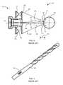
- FIG. 3depicts a two-dimensional data matrix symbol 195 etched on the surface of a cylindrical object, e.g., a drill bit 190 .
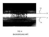
- a drill bit 190Presenting the exemplary drill bit 190 to the imaging system 100 will produce an image of the symbol 195 as shown in FIG. 4 .
- a brightly illuminated bandcan be observed between the regions defined as lines P 175 and Q 165 .
- the illumination that strikes the remaining portion of the objectdoes not reflect into the optics of the imaging system 100 , and therefore, the image is too dark to produce a clear representation of the data matrix symbol so that decoding algorithms can be applied to decode the symbol.
- an image of the data matrix symbol 195will be formed like that shown in FIG. 7 .
- the entire data matrix symbol 195is visible, since the region defined as the field of view between point A 145 and point B 135 receive diffuse illumination, and therefore, decoding algorithms operating on the image can readily extract the encoded information.
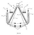
- FIG. 9shows an alternate embodiment of the implementation of the diffuser 300 with a passive light pipe 800 , shown in cross section relative to the lens 130 , to provide selectively exclusive dark field illumination or diffuse illumination.
- a color specific dark field illumination 835is projected into the light pipe 800 .
- the diffuser 300is fabricated with a material 840 having a color characteristic different from the color of the color specific dark field illumination 835 , and illuminated with color specific bright field illumination 825 that matches the color characteristic of the material 840 .
- the color specific dark field illuminationis exclusively actuated, the low angle dark field illumination is projected onto the object 105 , and any scattered illumination reflecting from the object 105 and then the diffuser 300 will not be converted into totally diffuse illumination.
- the color specific dark field illumination 835is red, and the color specific bright field illumination is blue, with the material 840 having a blue color.
- the red dark field illumination 835is turned on, with the blue bright field illumination turned off. The low angle red illumination striking the object, if scattered to reflect off the blue colored material 840 of the diffuser 300 , will not appear bright in an image, and therefore not contribute to the illumination of the object with totally diffuse illumination.
- the blue bright field illumination 825is turned on, the blue colored material 840 of the diffuser will transmit and diffuse the illumination to provide totally diffuse illumination of the object 105 within the field of view, depicted as the region defined by lines 150 .
- alternative color characteristicssuch as red/infrared can be employed according to the illustrative embodiment of FIG. 9 .
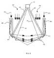
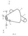
- FIG. 10shows another illustrative embodiment of the implementation of the diffuser 300 with a passive light pipe 800 , shown in cross section relative to the lens 130 , to provide selectively exclusive dark field illumination or diffuse illumination.
- dark field illumination 810is projected into the light pipe 800 to produce low angle dark field illumination while the bright field illumination 820 is turned off.
- a light absorbing foil 860such as a neutral density filter material is applied to the interior surface of the diffuser 300 .
- Low angle dark field illumination that reflects off the object 105is absorbed by the foil filter 860 so that totally diffuse illumination is not reflected back onto the object. If diffuse illumination is desired, either instead of dark field illumination, or in combination with dark field illumination, the bright field illumination 820 is turned on.
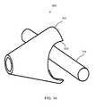
- the conical diffuser 300can be positioned to diffuse the dark field illumination from the dark field illuminators 875 , or optionally constructed to permit illumination from the dark field illuminators 875 to project onto the object at low angle without being diffused.
- This optional configurationcan be achieved by inserting the conical diffuser 300 further into the active light pipe 870 toward the lens 130 to expose the dark field illuminators 875 , or by constructing the conical diffuser 300 to have a transparent optical property at the distal end where it is disposed in front of the dark field illuminators 875 .
- the conical diffuser 300can be optionally removed from the image formation system 151 so that the hand held scanning appliance 102 can be operated without diffuse illumination. This condition may be desired if high intensity non-diffuse bright field illumination, or if exclusive dark field illumination is required.
- the removable aspect of the diffuser 300can be achieved by unscrewing the threaded collar 880 to remove the diffuser 300 , and re-threading the collar 880 without the diffuser in place.
Landscapes
- Physics & Mathematics (AREA)
- Engineering & Computer Science (AREA)
- Electromagnetism (AREA)
- Artificial Intelligence (AREA)
- Toxicology (AREA)
- General Health & Medical Sciences (AREA)
- Health & Medical Sciences (AREA)
- Computer Vision & Pattern Recognition (AREA)
- General Physics & Mathematics (AREA)
- Theoretical Computer Science (AREA)
- Image Input (AREA)
- Stroboscope Apparatuses (AREA)
- Facsimile Scanning Arrangements (AREA)
Abstract
Description
Claims (24)
Priority Applications (4)
| Application Number | Priority Date | Filing Date | Title |
|---|---|---|---|
| US12/573,402US8286878B2 (en) | 2004-12-16 | 2009-10-05 | Hand held symbology reader illumination diffuser |
| US13/623,367US9361495B2 (en) | 2004-12-16 | 2012-09-20 | Hand held symbology reader illumination diffuser |
| US13/971,320US9292724B1 (en) | 2004-12-16 | 2013-08-20 | Hand held symbology reader illumination diffuser with aimer optics |
| US15/173,780US20170132441A1 (en) | 2004-12-16 | 2016-06-06 | Hand held symbology reader illumination diffuser |
Applications Claiming Priority (2)
| Application Number | Priority Date | Filing Date | Title |
|---|---|---|---|
| US11/014,478US7617984B2 (en) | 2004-12-16 | 2004-12-16 | Hand held symbology reader illumination diffuser |
| US12/573,402US8286878B2 (en) | 2004-12-16 | 2009-10-05 | Hand held symbology reader illumination diffuser |
Related Parent Applications (1)
| Application Number | Title | Priority Date | Filing Date |
|---|---|---|---|
| US11/014,478ContinuationUS7617984B2 (en) | 2004-12-16 | 2004-12-16 | Hand held symbology reader illumination diffuser |
Related Child Applications (1)
| Application Number | Title | Priority Date | Filing Date |
|---|---|---|---|
| US13/623,367ContinuationUS9361495B2 (en) | 2004-12-16 | 2012-09-20 | Hand held symbology reader illumination diffuser |
Publications (2)
| Publication Number | Publication Date |
|---|---|
| US20100020539A1 US20100020539A1 (en) | 2010-01-28 |
| US8286878B2true US8286878B2 (en) | 2012-10-16 |
Family
ID=35965926
Family Applications (4)
| Application Number | Title | Priority Date | Filing Date |
|---|---|---|---|
| US11/014,478Active2027-08-06US7617984B2 (en) | 2004-12-16 | 2004-12-16 | Hand held symbology reader illumination diffuser |
| US12/573,402Expired - Fee RelatedUS8286878B2 (en) | 2004-12-16 | 2009-10-05 | Hand held symbology reader illumination diffuser |
| US13/623,367Expired - Fee RelatedUS9361495B2 (en) | 2004-12-16 | 2012-09-20 | Hand held symbology reader illumination diffuser |
| US15/173,780AbandonedUS20170132441A1 (en) | 2004-12-16 | 2016-06-06 | Hand held symbology reader illumination diffuser |
Family Applications Before (1)
| Application Number | Title | Priority Date | Filing Date |
|---|---|---|---|
| US11/014,478Active2027-08-06US7617984B2 (en) | 2004-12-16 | 2004-12-16 | Hand held symbology reader illumination diffuser |
Family Applications After (2)
| Application Number | Title | Priority Date | Filing Date |
|---|---|---|---|
| US13/623,367Expired - Fee RelatedUS9361495B2 (en) | 2004-12-16 | 2012-09-20 | Hand held symbology reader illumination diffuser |
| US15/173,780AbandonedUS20170132441A1 (en) | 2004-12-16 | 2016-06-06 | Hand held symbology reader illumination diffuser |
Country Status (3)
| Country | Link |
|---|---|
| US (4) | US7617984B2 (en) |
| JP (2) | JP5253812B2 (en) |
| WO (1) | WO2006065619A1 (en) |
Cited By (11)
| Publication number | Priority date | Publication date | Assignee | Title |
|---|---|---|---|---|
| US20110024506A1 (en)* | 2004-12-21 | 2011-02-03 | Laurens Nunnink | Low profile illumination for direct part mark readers |
| US20120235037A1 (en)* | 2011-03-16 | 2012-09-20 | Generalplus Technology Inc. | Optical identification module device and optical reader having the same |
| US8740078B2 (en) | 2003-10-24 | 2014-06-03 | Cognex Technology And Investment Corporation | Method and apparatus for providing omnidirectional lighting in a scanning device |
| US9004363B2 (en) | 2012-04-27 | 2015-04-14 | Symbol Technologies, Inc. | Diffuser engine for barcode imaging scanner |
| US9070031B2 (en) | 2003-10-24 | 2015-06-30 | Cognex Technology And Investment Llc | Integrated illumination assembly for symbology reader |
| US9292724B1 (en) | 2004-12-16 | 2016-03-22 | Cognex Corporation | Hand held symbology reader illumination diffuser with aimer optics |
| US9329332B2 (en) | 2003-10-24 | 2016-05-03 | Cognex Corporation | Light pipe illumination system and method |
| US9361495B2 (en) | 2004-12-16 | 2016-06-07 | Cognex Technology And Investment Llc | Hand held symbology reader illumination diffuser |
| US9405951B2 (en) | 2005-10-24 | 2016-08-02 | Cognex Technology And Investment Llc | Integrated illumination assembly for symbology reader |
| US9536124B1 (en) | 2003-10-24 | 2017-01-03 | Cognex Corporation | Integrated illumination assembly for symbology reader |
| US10210369B2 (en) | 2010-12-23 | 2019-02-19 | Cognex Corporation | Mark reader with reduced trigger-to-decode response time |
Families Citing this family (50)
| Publication number | Priority date | Publication date | Assignee | Title |
|---|---|---|---|---|
| US9092841B2 (en) | 2004-06-09 | 2015-07-28 | Cognex Technology And Investment Llc | Method and apparatus for visual detection and inspection of objects |
| US8127247B2 (en) | 2004-06-09 | 2012-02-28 | Cognex Corporation | Human-machine-interface and method for manipulating data in a machine vision system |
| US8243986B2 (en) | 2004-06-09 | 2012-08-14 | Cognex Technology And Investment Corporation | Method and apparatus for automatic visual event detection |
| US8891852B2 (en) | 2004-06-09 | 2014-11-18 | Cognex Technology And Investment Corporation | Method and apparatus for configuring and testing a machine vision detector |
| US20050276445A1 (en)* | 2004-06-09 | 2005-12-15 | Silver William M | Method and apparatus for automatic visual detection, recording, and retrieval of events |
| US7720315B2 (en) | 2004-11-12 | 2010-05-18 | Cognex Technology And Investment Corporation | System and method for displaying and using non-numeric graphic elements to control and monitor a vision system |
| US9292187B2 (en) | 2004-11-12 | 2016-03-22 | Cognex Corporation | System, method and graphical user interface for displaying and controlling vision system operating parameters |
| US7636449B2 (en) | 2004-11-12 | 2009-12-22 | Cognex Technology And Investment Corporation | System and method for assigning analysis parameters to vision detector using a graphical interface |
| US7963448B2 (en) | 2004-12-22 | 2011-06-21 | Cognex Technology And Investment Corporation | Hand held machine vision method and apparatus |
| US9552506B1 (en) | 2004-12-23 | 2017-01-24 | Cognex Technology And Investment Llc | Method and apparatus for industrial identification mark verification |
| DE102005005536A1 (en)* | 2005-02-07 | 2006-08-10 | Sick Ag | code reader |
| US8061610B2 (en)* | 2005-10-24 | 2011-11-22 | Cognex Technology And Investment Corporation | System and method for employing color illumination and color filtration in a symbology reader |
| US7965887B2 (en)* | 2005-12-01 | 2011-06-21 | Cognex Technology And Investment Corp. | Method of pattern location using color image data |
| US7614563B1 (en) | 2005-12-29 | 2009-11-10 | Cognex Technology And Investment Corporation | System and method for providing diffuse illumination in a symbology reader |
| US8108176B2 (en) | 2006-06-29 | 2012-01-31 | Cognex Corporation | Method and apparatus for verifying two dimensional mark quality |
| US7984854B2 (en)* | 2006-07-17 | 2011-07-26 | Cognex Corporation | Method and apparatus for multiplexed symbol decoding |
| US8016199B2 (en)* | 2006-12-14 | 2011-09-13 | Cognex Corporation | Illumination devices for image acquisition systems |
| US7537164B2 (en) | 2006-12-15 | 2009-05-26 | Symbol Technologies Inc. | System and method for reading codes on a specular background |
| DE102007043609B4 (en) | 2007-09-13 | 2014-05-28 | Ioss Intelligente Optische Sensoren & Systeme Gmbh | Integrated lighting device for an optical code reader |
| US9734376B2 (en) | 2007-11-13 | 2017-08-15 | Cognex Corporation | System and method for reading patterns using multiple image frames |
| US20090218403A1 (en)* | 2008-02-29 | 2009-09-03 | Eugene Joseph | Arrangement for and method of accurately aiming at direct part markings prior to being imaged and electro-optically read |
| JP5240137B2 (en)* | 2009-09-10 | 2013-07-17 | 株式会社デンソーウェーブ | Optical information reader |
| JP5310422B2 (en)* | 2009-09-11 | 2013-10-09 | 株式会社デンソーウェーブ | Optical information reader |
| FI20096192A7 (en)* | 2009-11-17 | 2011-05-18 | Optomed Oy | Lighting the subject |
| US9135484B2 (en) | 2010-09-28 | 2015-09-15 | Datalogic ADC, Inc. | Data reader with light source arrangement for improved illumination |
| US8746924B2 (en) | 2011-03-09 | 2014-06-10 | Rolls-Royce Corporation | Illumination system with illumination shield |
| USD682277S1 (en)* | 2011-12-30 | 2013-05-14 | Datalogic Ip Tech S.R.L. | Coded information reader |
| WO2013184970A2 (en) | 2012-06-08 | 2013-12-12 | Datalogic ADC, Inc. | Imaging reader with improved illumination |
| USD692004S1 (en)* | 2012-08-31 | 2013-10-22 | Megaviz Limited | Barcode scanner and radio frequency identification reader combo |
| US8847150B2 (en) | 2012-10-08 | 2014-09-30 | Symbol Technologies, Inc. | Object detecting system for imaging-based barcode readers |
| US9600703B2 (en) | 2013-03-15 | 2017-03-21 | Cognex Corporation | Systems and methods for sorting image acquisition settings for pattern stitching and decoding using multiple captured images |
| US9104932B2 (en) | 2013-03-15 | 2015-08-11 | Cognex Corporation | Systems and methods for pattern stitching and decoding using multiple captured images |
| USD730357S1 (en) | 2013-07-03 | 2015-05-26 | Hand Held Products, Inc. | Scanner |
| US8857720B1 (en)* | 2013-10-24 | 2014-10-14 | The Code Corporation | Diffuse bright field illumination system for a barcode reader |
| USD808076S1 (en)* | 2015-07-23 | 2018-01-16 | Koninklijke Philips N.V. | Flash lamp epilator |
| JP2017091332A (en)* | 2015-11-13 | 2017-05-25 | 株式会社キーエンス | Portable optical reading device |
| TWI578787B (en)* | 2016-03-18 | 2017-04-11 | 圓展科技股份有限公司 | Image capture device with automatic white balance function and adjustment method for automatic white balance |
| US9569653B1 (en) | 2016-06-13 | 2017-02-14 | Datalogic IP Tech, S.r.l. | Dark field illumination system obtained in a tilted plane |
| USD832845S1 (en)* | 2016-08-01 | 2018-11-06 | Hand Held Products, Inc. | Optical scanner |
| CN107944315B (en) | 2016-10-12 | 2023-08-04 | 手持产品公司 | Mobile imaging bar code scanner |
| EP3309706B1 (en)* | 2016-10-12 | 2020-01-01 | Hand Held Products, Inc. | Mobile imaging barcode scanner |
| CN106555938A (en)* | 2016-11-28 | 2017-04-05 | 北京慧眼智行科技有限公司 | A kind of illuminator of hide information collection |
| CN117556839A (en) | 2016-12-28 | 2024-02-13 | 手持产品公司 | Illuminator for DPM scanner |
| EP3635611B1 (en) | 2017-06-06 | 2021-04-21 | Sicpa Holding Sa | An illumination device for an optical system of a reader apparatus |
| USD848429S1 (en)* | 2017-11-08 | 2019-05-14 | Lee Seng Fook | Hand held 3D scanning device with feedback system |
| USD848428S1 (en)* | 2017-11-08 | 2019-05-14 | Lee Seng Fook | Hand held 3D scanning device |
| TWI662353B (en)* | 2018-07-13 | 2019-06-11 | 松翰科技股份有限公司 | Optical image sensing module |
| DE102019119501A1 (en) | 2019-07-18 | 2021-01-21 | Ioss Intelligente Optische Sensoren & Systeme Gmbh | Passive lighting device |
| DE102020134734A1 (en)* | 2020-12-22 | 2022-06-23 | Ioss Intelligente Optische Sensoren & Systeme Gmbh | Attachment optics, system and method for using attachment optics |
| CN222070957U (en)* | 2024-03-19 | 2024-11-26 | 荣谕科技(成都)有限公司 | Head-mounted display device |
Citations (210)
| Publication number | Priority date | Publication date | Assignee | Title |
|---|---|---|---|---|
| US2357378A (en) | 1941-12-01 | 1944-09-05 | Bausch & Lomb | Microscope illuminator |
| US3726998A (en) | 1971-08-09 | 1973-04-10 | Phonocopy Inc | Light pipe illuminated scan reader |
| US3857626A (en) | 1971-12-10 | 1974-12-31 | Bausch & Lomb | Microscope coaxial illumination apparatus |
| US3961198A (en) | 1975-04-28 | 1976-06-01 | Rockwell International Corporation | Visually alignable sensor wand which excludes unwanted light from a sensor system |
| US4240748A (en)* | 1978-06-26 | 1980-12-23 | Caere Corporation | Hand-held optical character recognition wand with visual aligner |
| US4282425A (en) | 1979-07-25 | 1981-08-04 | Norand Corporation | Instant portable bar code reader |
| US4570057A (en) | 1981-12-28 | 1986-02-11 | Norand Corporation | Instant portable bar code reader |
| JPS6134681Y2 (en) | 1977-12-13 | 1986-10-08 | ||
| US4743773A (en) | 1984-08-23 | 1988-05-10 | Nippon Electric Industry Co., Ltd. | Bar code scanner with diffusion filter and plural linear light source arrays |
| US4766300A (en) | 1984-08-06 | 1988-08-23 | Norand Corporation | Instant portable bar code reader |
| EP0185782B1 (en) | 1984-12-28 | 1989-03-15 | International Business Machines Corporation | Waveguide for an optical near-field microscope |
| US4820911A (en) | 1986-07-11 | 1989-04-11 | Photographic Sciences Corporation | Apparatus for scanning and reading bar codes |
| DE3737792A1 (en) | 1987-11-06 | 1989-05-18 | Hannes Burkhardt | Bar-code reader |
| US4894523A (en) | 1981-12-28 | 1990-01-16 | Norand Corporation | Instant portable bar code reader |
| EP0356680A1 (en) | 1988-08-11 | 1990-03-07 | Siemens Aktiengesellschaft | Optical recording apparatus for an image-processing system |
| US5019699A (en) | 1988-08-31 | 1991-05-28 | Norand Corporation | Hand-held optical character reader with means for instantaneously reading information from a predetermined area at an optical sensing area |
| DE4003983C1 (en) | 1990-02-09 | 1991-08-29 | Abos Automation, Bildverarbeitung, Optische Systeme Gmbh, 8057 Eching, De | Automated monitoring of space=shape data for mfg. semiconductors - compares image signals for defined illumination angle range with master signals, to determine defects |
| DE3931044C2 (en) | 1989-09-16 | 1992-01-02 | Dirk R. H. 6101 Bickenbach De Dickfeld | |
| US5149948A (en) | 1990-07-16 | 1992-09-22 | Computer Identics | Improved bar code reader system for reading bar codes under high specular reflection conditions with a variety of surface effects |
| US5177346A (en) | 1989-12-13 | 1993-01-05 | Computer Identics | Bar code reader system for reading bar code labels with a highly specular and low contrast surface |
| US5202817A (en) | 1989-06-07 | 1993-04-13 | Norand Corporation | Hand-held data capture system with interchangeable modules |
| US5227614A (en) | 1986-08-15 | 1993-07-13 | Norand Corporation | Core computer processor module, and peripheral shell module assembled to form a pocket size data capture unit |
| US5239169A (en) | 1991-05-20 | 1993-08-24 | Microscan Systems Incorporated | Optical signal processor for barcode reader |
| US5258606A (en) | 1981-12-28 | 1993-11-02 | Norand Corporation | Instant portable bar code reader |
| US5291009A (en) | 1992-02-27 | 1994-03-01 | Roustaei Alexander R | Optical scanning head |
| US5313373A (en) | 1992-11-25 | 1994-05-17 | United Parcel Service Of America, Inc. | Apparatus for the uniform illumination of a surface |
| US5319182A (en) | 1992-03-04 | 1994-06-07 | Welch Allyn, Inc. | Integrated solid state light emitting and detecting array and apparatus employing said array |
| US5331176A (en) | 1992-04-10 | 1994-07-19 | Veritec Inc. | Hand held two dimensional symbol reader with a symbol illumination window |
| US5349172A (en) | 1992-02-27 | 1994-09-20 | Alex Roustaei | Optical scanning head |
| US5354977A (en) | 1992-02-27 | 1994-10-11 | Alex Roustaei | Optical scanning head |
| US5359185A (en) | 1992-05-11 | 1994-10-25 | Norand Corporation | Chromatic ranging method and apparatus for reading optically readable information over a substantial range of distances |
| US5367439A (en) | 1992-12-24 | 1994-11-22 | Cognex Corporation | System for frontal illumination |
| US5374817A (en) | 1988-05-11 | 1994-12-20 | Symbol Technologies, Inc. | Pre-objective scanner with flexible optical support |
| US5378883A (en) | 1991-07-19 | 1995-01-03 | Omniplanar Inc. | Omnidirectional wide range hand held bar code reader |
| US5406060A (en) | 1993-05-06 | 1995-04-11 | Opticon Inc. | Bar code reader for sensing at an acute angle |
| US5408084A (en) | 1993-02-18 | 1995-04-18 | United Parcel Service Of America, Inc. | Method and apparatus for illumination and imaging of a surface using 2-D LED array |
| US5414251A (en) | 1992-03-12 | 1995-05-09 | Norand Corporation | Reader for decoding two-dimensional optical information |
| US5430285A (en) | 1993-08-20 | 1995-07-04 | Welch Allyn, Inc. | Illumination system for optical reader |
| US5442247A (en) | 1991-12-20 | 1995-08-15 | Minebea Kabushiki-Kaisha | Outer-rotor type spindle motor with a reduced thickness in the axial direction |
| US5449892A (en) | 1991-10-29 | 1995-09-12 | Nippondenso Co., Ltd. | Information reading apparatus |
| US5461417A (en) | 1993-02-16 | 1995-10-24 | Northeast Robotics, Inc. | Continuous diffuse illumination method and apparatus |
| US5463214A (en) | 1994-03-04 | 1995-10-31 | Welch Allyn, Inc. | Apparatus for optimizing throughput in decoded-output scanners and method of using same |
| US5469294A (en) | 1992-05-01 | 1995-11-21 | Xrl, Inc. | Illumination system for OCR of indicia on a substrate |
| US5481098A (en) | 1993-11-09 | 1996-01-02 | Spectra-Physics Scanning Systems, Inc. | Method and apparatus for reading multiple bar code formats |
| US5484994A (en) | 1993-10-18 | 1996-01-16 | Roustaei; Alexander | Optical scanning head with improved resolution |
| US5500516A (en) | 1994-08-30 | 1996-03-19 | Norand Corporation | Portable oblique optical reader system and method |
| US5504367A (en) | 1994-03-21 | 1996-04-02 | Intermec Corporation | Symbology reader illumination system |
| US5504317A (en) | 1994-01-05 | 1996-04-02 | Opticon, Inc. | Optical reader |
| US5515452A (en) | 1992-12-31 | 1996-05-07 | Electroglas, Inc. | Optical character recognition illumination method and system |
| US5514858A (en) | 1995-02-10 | 1996-05-07 | Intermec Corporation | Method and apparatus for decoding unresolved complex multi-width bar code symbology profiles |
| US5569902A (en) | 1995-01-17 | 1996-10-29 | Welch Allyn, Inc. | Contact two-dimensional bar code reader having pressure actuated switch |
| US5576527A (en)* | 1994-06-20 | 1996-11-19 | Asahi Kogaku Kogyo Kabushiki Kaisha | Optical reader for information pattern representing coded data |
| US5585616A (en) | 1995-05-05 | 1996-12-17 | Rockwell International Corporation | Camera for capturing and decoding machine-readable matrix symbol images applied to reflective surfaces |
| US5586212A (en) | 1994-07-06 | 1996-12-17 | Hewlett-Packard | Optical wave guide for hand-held scanner |
| US5591955A (en) | 1993-05-11 | 1997-01-07 | Laser; Vadim | Portable data file readers |
| US5598007A (en) | 1994-03-21 | 1997-01-28 | Intermec Corporation | Symbology reader with fixed focus spotter beam |
| US5606160A (en) | 1993-03-25 | 1997-02-25 | Asahi Kogaku Kogyo Kabushiki Kaisha | Symbol reading device |
| US5619029A (en)* | 1995-04-04 | 1997-04-08 | Rockwell International Corporation | Imaging enhancement for touch cameras |
| US5623137A (en) | 1993-08-20 | 1997-04-22 | Welch Allyn, Inc. | Illumination apparatus for optical readers |
| US5654533A (en) | 1992-10-26 | 1997-08-05 | Kabushiki Kaisha Tec | Apparatus and method for reading two-dimensional symbols |
| US5654540A (en) | 1995-08-17 | 1997-08-05 | Stanton; Stuart | High resolution remote position detection using segmented gratings |
| US5659167A (en) | 1994-04-05 | 1997-08-19 | Metanetics Corporation | Visually interactive decoding of dataforms |
| US5696321A (en) | 1994-10-18 | 1997-12-09 | Hitachi, Ltd. | Thermal-type air flow measuring instrument with fluid-direction judging capability |
| US5697699A (en) | 1993-09-09 | 1997-12-16 | Asahi Kogaku Kogyo Kabushiki Kaisha | Lighting apparatus |
| US5703348A (en) | 1994-12-26 | 1997-12-30 | Kabushiki Kaisha Tec | Hand-held optical code reader |
| US5715095A (en) | 1994-02-22 | 1998-02-03 | Matsushita Electric Industrial Co., Ltd. | Color separating device and color image reading device incorporating same |
| US5723868A (en) | 1995-05-15 | 1998-03-03 | Welch Allyn, Inc. | Illuminating assembly for use with bar code readers |
| US5734153A (en) | 1985-02-28 | 1998-03-31 | Symbol Technologies, Inc. | Hand-held scanning head with aiming beam |
| DE4123916C2 (en) | 1990-07-19 | 1998-04-09 | Reinhard Malz | Method and device for dynamic detection and classification of surface features and defects of an object |
| US5743633A (en) | 1995-12-27 | 1998-04-28 | Physical Optics Corporation | Bar code illuminator |
| US5750974A (en) | 1995-04-13 | 1998-05-12 | Keyence Corporation | Lighting apparatus having light emitting diodes arranged in a plurality of planes on a printed circuit board |
| US5756981A (en) | 1992-02-27 | 1998-05-26 | Symbol Technologies, Inc. | Optical scanner for reading and decoding one- and-two-dimensional symbologies at variable depths of field including memory efficient high speed image processing means and high accuracy image analysis means |
| US5773810A (en) | 1996-03-29 | 1998-06-30 | Welch Allyn, Inc. | Method for generating real time degree of focus signal for handheld imaging device |
| US5777314A (en) | 1992-02-27 | 1998-07-07 | Symbol | Optical scanner with fixed focus optics |
| US5783811A (en) | 1995-06-26 | 1998-07-21 | Metanetics Corporation | Portable data collection device with LED targeting and illumination assembly |
| US5786586A (en)* | 1995-01-17 | 1998-07-28 | Welch Allyn, Inc. | Hand-held optical reader having a detachable lens-guide assembly |
| US5793033A (en) | 1996-03-29 | 1998-08-11 | Metanetics Corporation | Portable data collection device with viewing assembly |
| US5811784A (en) | 1995-06-26 | 1998-09-22 | Telxon Corporation | Extended working range dataform reader |
| US5859418A (en) | 1996-01-25 | 1999-01-12 | Symbol Technologies, Inc. | CCD-based bar code scanner with optical funnel |
| US5861910A (en) | 1996-04-02 | 1999-01-19 | Mcgarry; E. John | Image formation apparatus for viewing indicia on a planar specular substrate |
| US5894348A (en) | 1994-06-17 | 1999-04-13 | Kensington Laboratories, Inc. | Scribe mark reader |
| US5903391A (en)* | 1996-03-27 | 1999-05-11 | Kimoto Co., Ltd. | Optical film |
| US5907148A (en) | 1994-08-22 | 1999-05-25 | Casio Computer Co., Ltd. | Portable reading apparatus for scan-reading a code using a laser light beam |
| US5920643A (en) | 1997-05-16 | 1999-07-06 | Northeast Robotics Llc | Flexible lighting element circuit and method of manufacturing the same |
| US5923020A (en) | 1995-03-31 | 1999-07-13 | Lintec Corporation | Lighting apparatus |
| US5979763A (en) | 1995-10-13 | 1999-11-09 | Metanetics Corporation | Sub-pixel dataform reader with dynamic noise margins |
| US5984494A (en) | 1995-09-08 | 1999-11-16 | Jimmy G. Cook | Light shield for an illumination system |
| US6011586A (en) | 1996-12-04 | 2000-01-04 | Cognex Corporation | Low-profile image formation apparatus |
| US6022124A (en) | 1997-08-19 | 2000-02-08 | Ppt Vision, Inc. | Machine-vision ring-reflector illumination system and method |
| US6034379A (en) | 1996-03-01 | 2000-03-07 | Intermec Ip Corp. | Code reader having replaceable optics assemblies supporting multiple illuminators |
| US6036095A (en) | 1996-05-17 | 2000-03-14 | Asahi Kogaku Kogyo Kabushiki Kaisha | Data symbol reader with observation window |
| US6039255A (en) | 1996-08-28 | 2000-03-21 | Asahi Kogaku Kogyo Kabushiki Kaisha | Data symbol reading apparatus |
| US6039254A (en) | 1993-03-18 | 2000-03-21 | Siemens Aktiengesellschaft | Method for imaging bar codes |
| US6042012A (en) | 1994-12-23 | 2000-03-28 | Spectra-Physics Scanning Systems, Inc. | Method and apparatus for reading images without need for self-generated illumination source |
| US6045047A (en) | 1995-01-17 | 2000-04-04 | Welch Allyn Data Collection, Inc. | Two-dimensional part reader having a focussing guide |
| US6060722A (en) | 1995-05-15 | 2000-05-09 | Havens; William H. | Optical reader having illumination assembly including improved aiming pattern generator |
| US6073852A (en) | 1996-06-06 | 2000-06-13 | Asahi Kogaku Kogyo Kabushiki Kaisha | Data symbol reader with an observation window |
| JP2000231600A (en) | 1998-12-22 | 2000-08-22 | Datalogig Spa | Automatic adjustment method of characteristic variables in optical code reading system |
| US6105869A (en) | 1997-10-31 | 2000-08-22 | Microscan Systems, Incorporated | Symbol reading device including optics for uniformly illuminating symbology |
| US6119939A (en) | 1998-07-08 | 2000-09-19 | Welch Allyn, Inc. | Optical assembly for barcode scanner |
| US6141046A (en) | 1994-10-25 | 2000-10-31 | Roth; Stephen Anthony | Electronic camera having an illuminator with dispersing ring lens |
| US6158661A (en) | 1981-12-28 | 2000-12-12 | Intermec Ip Corp. | Instant portable bar code reader |
| US6164544A (en) | 1998-07-08 | 2000-12-26 | Welch Allyn Data Collection, Inc. | Adjustable illumination system for a barcode scanner |
| US6210013B1 (en) | 1996-03-10 | 2001-04-03 | Imperial Chemical Industries Plc | Refrigerator comprising edge-lit panel illumination system |
| US6223986B1 (en) | 1997-04-17 | 2001-05-01 | Psc Scanning, Inc. | Aiming aid for optical data reading |
| US6234397B1 (en) | 1998-10-22 | 2001-05-22 | Symbol Technologies, Inc. | Techniques for reading two dimensional code, including maxicode |
| US6247645B1 (en) | 1999-01-25 | 2001-06-19 | International Business Machines Corporation | Optical reader with combined housing and light pipe |
| US6250551B1 (en) | 1998-06-12 | 2001-06-26 | Symbol Technologies, Inc. | Autodiscrimination and line drawing techniques for code readers |
| US6260763B1 (en) | 1996-02-06 | 2001-07-17 | Psc Scanning, Inc. | Integral illumination source/collection lens assembly for data reading system |
| US6267294B1 (en) | 1998-09-11 | 2001-07-31 | Robotic Vision Systems Inc. | Method of operating a charge coupled device in an accelerated mode, and in conjunction with an optical symbology imager |
| US6283374B1 (en) | 1998-09-11 | 2001-09-04 | Robotic Vision Systems, Inc. | Symbology imaging and reading apparatus and method |
| US20010026301A1 (en) | 2000-03-31 | 2001-10-04 | Hideo Fukazawa | Ink jet recording apparatus and ink tank mounted on such ink jet recording apparatus |
| US20010027999A1 (en) | 1998-09-11 | 2001-10-11 | Lee Jason J. | Focus and illumination analysis algorithm for imaging device |
| JP2001307011A (en) | 2000-04-27 | 2001-11-02 | Matsushita Electric Ind Co Ltd | Optical information reader |
| DE10026301A1 (en) | 2000-05-26 | 2001-11-29 | Sick Ag | Image processing method and apparatus |
| US20020000472A1 (en) | 1999-08-04 | 2002-01-03 | John R. Hattersley | Optical symbol scanner with low angle illumination |
| US6340114B1 (en) | 1998-06-12 | 2002-01-22 | Symbol Technologies, Inc. | Imaging engine and method for code readers |
| US6341878B1 (en) | 1999-08-31 | 2002-01-29 | Cognex Corporation | Method and apparatus for providing uniform diffuse illumination to a surface |
| US6347163B2 (en) | 1994-10-26 | 2002-02-12 | Symbol Technologies, Inc. | System for reading two-dimensional images using ambient and/or projected light |
| US6347874B1 (en) | 2000-02-16 | 2002-02-19 | 3M Innovative Properties Company | Wedge light extractor with risers |
| US20020030094A1 (en) | 1997-02-10 | 2002-03-14 | Daniel Curry | Arrangement for and method of establishing a logical relationship among peripherals in a wireless local area network |
| US6360948B1 (en) | 1998-11-27 | 2002-03-26 | Denso Corporation | Method of reading two-dimensional code and storage medium thereof |
| US6385507B1 (en) | 1999-06-24 | 2002-05-07 | U.S. Philips Corporation | Illumination module |
| US6385352B1 (en) | 1994-10-26 | 2002-05-07 | Symbol Technologies, Inc. | System and method for reading and comparing two-dimensional images |
| US6394349B1 (en) | 1997-10-15 | 2002-05-28 | Denso Corporation | Optical information reader and recording medium |
| US20020074403A1 (en) | 1997-02-03 | 2002-06-20 | Mark Krichever | Extended range bar code reader |
| US20020096566A1 (en) | 2000-11-01 | 2002-07-25 | Welch Allyn, Inc. | Adjustable illumination system for a barcode scanner |
| US6429934B1 (en) | 1998-09-11 | 2002-08-06 | Robotic Vision Systems, Inc. | Optimal symbology illumination-apparatus and method |
| US20020104887A1 (en) | 1999-02-22 | 2002-08-08 | Symbol Technologies, Inc. | Hand-held data acquisition device |
| US6435411B1 (en) | 1997-04-21 | 2002-08-20 | Intermec Ip Corp. | Optoelectronic device for acquisition of images, in particular of bar codes |
| US20020125322A1 (en) | 2001-03-08 | 2002-09-12 | Mccall Melvin D. | Imaging module for optical reader comprising refractive diffuser |
| US20020170970A1 (en) | 2001-05-15 | 2002-11-21 | Welch Allyn Data Collection, Inc. | Optical reader having decoding and image capturing functionality |
| US6491223B1 (en) | 1996-09-03 | 2002-12-10 | Hand Held Products, Inc. | Autodiscriminating optical reader |
| US20030001018A1 (en) | 2001-05-02 | 2003-01-02 | Hand Held Products, Inc. | Optical reader comprising good read indicator |
| US6505778B1 (en) | 1998-07-17 | 2003-01-14 | Psc Scanning, Inc. | Optical reader with selectable processing characteristics for reading data in multiple formats |
| US6513714B1 (en) | 1998-09-14 | 2003-02-04 | Psc Scanning, Inc. | Character reconstruction and element level processing in bar code scanning system |
| US20030029917A1 (en) | 1999-10-04 | 2003-02-13 | Hand Held Products, Inc. | Optical reader for imaging module |
| US20030034394A1 (en) | 1999-10-04 | 2003-02-20 | Hand Held Products, Inc. | Optical reader comprising finely adjustable lens assembly |
| US20030058631A1 (en) | 2001-09-25 | 2003-03-27 | Kenji Yoneda | Lighting apparatus for insepection |
| US6542238B1 (en) | 1998-02-27 | 2003-04-01 | Matsushita Electric Industrial Co., Ltd. | Electronic component mounting apparatus |
| US20030062413A1 (en) | 1999-10-04 | 2003-04-03 | Hand Held Products, Inc. | Optical reader comprising multiple color illumination |
| US20030062418A1 (en) | 2001-01-22 | 2003-04-03 | Welch Allyn Data Collection, Inc. | Optical reader having partial frame operating mode |
| US6547146B1 (en) | 2000-05-03 | 2003-04-15 | Ipilot, Inc. | Method, system and apparatus for processing barcode data |
| US20030080187A1 (en) | 1998-06-01 | 2003-05-01 | Marco Piva | Apparatus and method for reading an optical code |
| US20030080189A1 (en) | 2001-10-26 | 2003-05-01 | Symbol Technologies, Inc. | Bar code reader including linear sensor array and hybrid camera and bar code reader |
| US6575367B1 (en) | 1998-11-05 | 2003-06-10 | Welch Allyn Data Collection, Inc. | Image data binarization methods enabling optical reader to read fine print indicia |
| CN1426570A (en) | 2000-03-02 | 2003-06-25 | 物理光学公司 | Scanner utilizing light pipe with diffuser |
| US6592040B2 (en) | 1998-03-20 | 2003-07-15 | Symbol Technologies, Inc. | Hand-held bar code reader with single printed circuit board |
| US6595422B1 (en) | 1999-06-23 | 2003-07-22 | Assure Systems, Inc. | Bar code reader |
| US6607132B1 (en) | 1998-03-20 | 2003-08-19 | Symbol Technologies, Inc. | Bar code reader with an integrated scanning component module mountable on printed circuit board |
| US6607128B1 (en) | 1998-07-08 | 2003-08-19 | Welch Allyn Data Collection Inc. | Optical assembly for barcode scanner |
| US20030163623A1 (en) | 2002-02-22 | 2003-08-28 | Yeung Chi Ping | Image capture device |
| US6621065B1 (en) | 1999-11-30 | 2003-09-16 | Mitutoyo Corporation | Imaging probe |
| US6661521B1 (en) | 1998-09-11 | 2003-12-09 | Robotic Vision Systems, Inc. | Diffuse surface illumination apparatus and methods |
| US6681037B1 (en) | 1999-05-27 | 2004-01-20 | Cognex Corporation | Apparatus for locating features of an object using varied illumination |
| US6689998B1 (en) | 2000-07-05 | 2004-02-10 | Psc Scanning, Inc. | Apparatus for optical distancing autofocus and imaging and method of using the same |
| US20040069855A1 (en) | 2002-10-15 | 2004-04-15 | Mehul Patel | Imaging bar code reader with moving beam simulation |
| US6760165B2 (en) | 2002-04-22 | 2004-07-06 | Symbol Technologies, Inc. | System and method for manufacturing an assembly including a housing and a window member therein |
| US20040156539A1 (en) | 2003-02-10 | 2004-08-12 | Asm Assembly Automation Ltd | Inspecting an array of electronic components |
| US6803088B2 (en) | 2002-10-24 | 2004-10-12 | Eastman Kodak Company | Reflection media for scannable information system |
| US6809847B2 (en) | 1999-04-27 | 2004-10-26 | Psc Scanning, Inc. | Scanner with synchronously switched optics |
| US20040217173A1 (en) | 2003-05-01 | 2004-11-04 | Lizotte Todd E | Method and apparatus for reading firearm microstamping |
| US20040238637A1 (en) | 2000-04-18 | 2004-12-02 | Metrologic Instruments, Inc. | Point of sale (POS) based bar code reading and cash register systems with integrated internet-enabled customer-kiosk terminals |
| US6831290B2 (en) | 2002-07-16 | 2004-12-14 | Strube, Inc. | Electro-optic fluid quantity measurement system |
| US20050029439A1 (en) | 2003-07-21 | 2005-02-10 | Beneficial Imaging Corporation | Method and apparatus for scanning an optical beam using an optical conduit |
| US6854650B2 (en)* | 2002-04-10 | 2005-02-15 | Microscan Systems, Inc. | Mirrored surface optical symbol scanner |
| US6860428B1 (en) | 1998-09-11 | 2005-03-01 | Robotic Vision Systems Inc. | Optical symbologies imager |
| US20050047723A1 (en) | 2001-05-25 | 2005-03-03 | Li Kenneth K. | Lensed tapered optical waveguide |
| US20050045725A1 (en) | 2003-08-25 | 2005-03-03 | Vladimir Gurevich | Axial chromatic aberration auto-focusing system and method |
| US20050087601A1 (en) | 2003-10-24 | 2005-04-28 | Gerst Carl W.Iii | Light pipe illumination system and method |
| WO2005043449A1 (en) | 2003-10-24 | 2005-05-12 | Cognex Technology And Investment Corporation | Method and apparatus for providing omnidirectional lighting in a scanning device |
| US20050117144A1 (en) | 2002-04-10 | 2005-06-02 | Bryan Greenway | Automated protein crystallization imaging |
| US6914679B2 (en) | 2001-12-18 | 2005-07-05 | Cognex Technology And Investment Corporation | Side light apparatus and method |
| US20050180037A1 (en) | 2004-02-18 | 2005-08-18 | Boulder Nonlinear Systems, Inc. | Electronic filter wheel |
| US20050199725A1 (en) | 2004-03-11 | 2005-09-15 | Pierre Craen | Optical adjustment for increased working range and performance in electro-optical readers |
| US20060027657A1 (en) | 2004-08-04 | 2006-02-09 | Laurens Ninnink | Method and apparatus for high resolution decoding of encoded symbols |
| US20060027659A1 (en) | 2003-08-01 | 2006-02-09 | Symbol Technologies, Inc. | Integrated exit window and imaging engine |
| US20060060653A1 (en) | 2004-09-23 | 2006-03-23 | Carl Wittenberg | Scanner system and method for simultaneously acquiring data images from multiple object planes |
| US7021542B2 (en) | 2003-08-01 | 2006-04-04 | Symbol Technologies, Inc. | Imaging and illumination engine for an optical code reader |
| US7025271B2 (en) | 2002-12-18 | 2006-04-11 | Symbol Technologies, Inc. | Imaging optical code reader having selectable depths of field |
| US7025273B2 (en) | 2002-12-18 | 2006-04-11 | Symbol Technologies, Inc. | Miniature auto focus voice coil actuator system |
| US7025272B2 (en) | 2002-12-18 | 2006-04-11 | Symbol Technologies, Inc. | System and method for auto focusing an optical code reader |
| US7038853B2 (en) | 1992-03-30 | 2006-05-02 | Symbol Technlogies, Inc. | Athermalized plastic lens |
| US7044377B2 (en) | 2003-08-01 | 2006-05-16 | Symbol Technologies Inc. | Plug-and-play imaging and illumination engine for an optical code reader |
| US20060133757A1 (en) | 2004-12-16 | 2006-06-22 | Laurens Nunnink | Hand held symbology reader illumination diffuser |
| US20060131419A1 (en) | 2004-12-21 | 2006-06-22 | Laurens Nunnink | Low profile illumination for direct part mark readers |
| US7090132B2 (en) | 2002-06-11 | 2006-08-15 | Hand Held Products, Inc. | Long range optical reader |
| US7128266B2 (en) | 2003-11-13 | 2006-10-31 | Metrologic Instruments. Inc. | Hand-supportable digital imaging-based bar code symbol reader supporting narrow-area and wide-area modes of illumination and image capture |
| US7131587B2 (en) | 2004-03-02 | 2006-11-07 | Symbol Technologies, Inc. | System and method for illuminating and reading optical codes imprinted or displayed on reflective surfaces |
| US20060266840A1 (en) | 2005-05-31 | 2006-11-30 | Symbol Technologies, Inc. | Feedback mechanism for scanner devices |
| US7159764B1 (en) | 2003-05-30 | 2007-01-09 | Intermec Ip Corp. | Versatile window system for information gathering systems |
| US7180052B1 (en) | 2005-09-13 | 2007-02-20 | Symbol Technologies, Inc. | Non-heavy metal optical bandpass filter in electro-optical readers |
| US7187825B2 (en) | 2003-12-17 | 2007-03-06 | Symbol Technologies, Inc. | System and method for extending viewing angle of light emitted from light pipe |
| US7204418B2 (en) | 2004-12-08 | 2007-04-17 | Symbol Technologies, Inc. | Pulsed illumination in imaging reader |
| US7204420B2 (en) | 2004-08-31 | 2007-04-17 | Symbol Technologies, Inc. | Scanner and method for eliminating specular reflection |
| US20070090193A1 (en) | 2005-10-24 | 2007-04-26 | Laurens Nunnink | Integrated illumination assembly for symbology reader |
| US7224540B2 (en) | 2005-01-31 | 2007-05-29 | Datalogic Scanning, Inc. | Extended depth of field imaging system using chromatic aberration |
| US20070152064A1 (en) | 2005-12-30 | 2007-07-05 | Laurens Nunnink | Diffuse light ring for reading encoded symbols |
| US7253384B2 (en) | 2005-03-23 | 2007-08-07 | Microscan Systems Incorporated | Focusing system using light source and image sensor |
| US20070206183A1 (en) | 1999-07-08 | 2007-09-06 | Ppt Vision, Inc. | Method and apparatus for auto-adjusting illumination |
| US7270274B2 (en) | 1999-10-04 | 2007-09-18 | Hand Held Products, Inc. | Imaging module comprising support post for optical reader |
| US7296749B2 (en) | 2004-01-23 | 2007-11-20 | Intermec Ip Corp. | Autofocus barcode scanner and the like employing micro-fluidic lens |
| US7306155B2 (en) | 1998-07-08 | 2007-12-11 | Hand Held Products, Inc. | Image sensor assembly for optical reader |
| US7314173B2 (en) | 1998-09-11 | 2008-01-01 | Lv Partners, L.P. | Optical reader with ultraviolet wavelength capability |
| US7360705B2 (en) | 2005-07-14 | 2008-04-22 | Intermec Ip Corp. | Apparatus and method for reading machine-readable symbols |
| US20080170380A1 (en) | 2006-09-29 | 2008-07-17 | Pastore Timothy M | Systems and/or devices for camera-based inspections |
| US7451917B2 (en) | 2002-01-11 | 2008-11-18 | Hand Held Products, Inc. | Transaction terminal comprising imaging module |
| US7490774B2 (en) | 2003-11-13 | 2009-02-17 | Metrologic Instruments, Inc. | Hand-supportable imaging based bar code symbol reader employing automatic light exposure measurement and illumination control subsystem integrated therein |
| US7520434B2 (en) | 2004-06-25 | 2009-04-21 | Intermec Ip Corp. | Reader for reading machine-readable symbols, for example bar code symbols |
| US7568628B2 (en) | 2005-03-11 | 2009-08-04 | Hand Held Products, Inc. | Bar code reading device with global electronic shutter control |
Family Cites Families (38)
| Publication number | Priority date | Publication date | Assignee | Title |
|---|---|---|---|---|
| JPS5362387A (en) | 1976-11-17 | 1978-06-03 | Hitachi Ltd | Illumination device for microscope |
| JPS59163677A (en)* | 1983-03-08 | 1984-09-14 | Tokyo Electric Co Ltd | Ocr hand scanner |
| JPS6134681A (en) | 1984-07-26 | 1986-02-18 | Tokyo Electric Co Ltd | Optical reader |
| JPS6318209A (en)* | 1986-07-10 | 1988-01-26 | Nec Corp | Illumination system |
| US5969321A (en) | 1986-08-08 | 1999-10-19 | Norand Corporation | Hand-held optically readable information set reader with operation over a range of distances |
| DE3802868A1 (en) | 1988-02-01 | 1989-08-03 | Philips Patentverwaltung | DISPLAY DEVICE |
| JPH04223583A (en) | 1990-12-26 | 1992-08-13 | Smk Corp | barcode reader device |
| GB9105969D0 (en) | 1991-03-21 | 1991-05-08 | Dansam Holdings Ltd | Bar-code reader |
| US5309277A (en) | 1992-06-19 | 1994-05-03 | Zygo Corporation | High intensity illuminator |
| US5422472A (en) | 1992-12-04 | 1995-06-06 | Psc, Inc. | Optical symbol (bar code) reading systems having an electro-optic receptor with embedded grating rings |
| JPH06350907A (en) | 1993-06-07 | 1994-12-22 | Fuji Photo Film Co Ltd | Electronic still camera |
| JP3153412B2 (en) | 1994-04-01 | 2001-04-09 | 旭光学工業株式会社 | Data symbol reading device |
| JP3629581B2 (en) | 1995-04-13 | 2005-03-16 | 株式会社キーエンス | Bar code reader |
| JP3612119B2 (en)* | 1995-08-25 | 2005-01-19 | 日立エンジニアリング株式会社 | Imaging device |
| US6330974B1 (en) | 1996-03-29 | 2001-12-18 | Intermec Ip Corp. | High resolution laser imager for low contrast symbology |
| US5690417A (en) | 1996-05-13 | 1997-11-25 | Optical Gaging Products, Inc. | Surface illuminator with means for adjusting orientation and inclination of incident illumination |
| JP3811235B2 (en) | 1996-11-05 | 2006-08-16 | オリンパス株式会社 | Bar code reader |
| US6784924B2 (en) | 1997-02-20 | 2004-08-31 | Eastman Kodak Company | Network configuration file for automatically transmitting images from an electronic still camera |
| US5949763A (en) | 1997-07-17 | 1999-09-07 | Ameritech Corporation | Method and apparatus for providing broadband access conferencing services |
| WO1999049347A1 (en)* | 1998-03-20 | 1999-09-30 | Auto Image Id, Inc. | Target illumination device |
| JP3593950B2 (en) | 1999-05-26 | 2004-11-24 | 株式会社デンソー | 2D code reader |
| US6407810B1 (en)* | 2000-03-10 | 2002-06-18 | Robotic Vision Systems, Inc. | Imaging system |
| US6855650B1 (en) | 2000-08-25 | 2005-02-15 | American Excelsior Company | Synthetic fiber filled erosion control blanket |
| US20020080187A1 (en) | 2000-10-02 | 2002-06-27 | Lawton Scott S. | Enhanced method and system for category selection |
| DE10113426A1 (en) | 2001-03-19 | 2002-09-26 | Gavitec Gmbh | Code reader incorporates illumination device for sidewards illumination of scanned code |
| JP4682474B2 (en) | 2001-07-25 | 2011-05-11 | 株式会社デンソー | Fluid pump |
| DE10228316A1 (en) | 2002-06-25 | 2004-01-22 | Schwan-Stabilo Schwanhäusser Gmbh & Co. Kg | Container for holding at least one pen |
| WO2004006438A2 (en) | 2002-07-08 | 2004-01-15 | Veritec, Inc. | Method for reading a symbol having encoded information |
| JP2004127215A (en)* | 2002-09-30 | 2004-04-22 | Aisin Engineering Kk | Code reader |
| JP2005122355A (en) | 2003-10-15 | 2005-05-12 | Matsushita Electric Ind Co Ltd | Optical information reader |
| DE10353345A1 (en) | 2003-11-14 | 2005-06-02 | Sick Ag | Connection module for connecting a sensor to a fieldbus |
| JP2007028088A (en) | 2005-07-14 | 2007-02-01 | Konica Minolta Holdings Inc | Imaging apparatus and image processing method |
| US8061610B2 (en) | 2005-10-24 | 2011-11-22 | Cognex Technology And Investment Corporation | System and method for employing color illumination and color filtration in a symbology reader |
| ATE484779T1 (en) | 2006-06-30 | 2010-10-15 | Sick Ag | CONNECTION MODULE FOR SENSORS |
| US7861037B2 (en) | 2007-06-27 | 2010-12-28 | Sandisk Corporation | Methods of auto starting with portable mass storage device |
| US8069289B2 (en) | 2008-07-31 | 2011-11-29 | Ametek, Inc. | Modbus register data formatting |
| JP5270400B2 (en) | 2009-02-26 | 2013-08-21 | 富士通コンポーネント株式会社 | Card connector |
| WO2013179089A1 (en) | 2012-05-30 | 2013-12-05 | Freescale Semiconductor, Inc. | Sequential logic circuit and method of providing setup timing violation tolerance therefor |
- 2004
- 2004-12-16USUS11/014,478patent/US7617984B2/enactiveActive
- 2005
- 2005-12-08JPJP2007546762Apatent/JP5253812B2/ennot_activeExpired - Fee Related
- 2005-12-08WOPCT/US2005/044452patent/WO2006065619A1/enactiveApplication Filing
- 2009
- 2009-10-05USUS12/573,402patent/US8286878B2/ennot_activeExpired - Fee Related
- 2012
- 2012-09-20USUS13/623,367patent/US9361495B2/ennot_activeExpired - Fee Related
- 2013
- 2013-03-04JPJP2013041470Apatent/JP5615952B2/enactiveActive
- 2016
- 2016-06-06USUS15/173,780patent/US20170132441A1/ennot_activeAbandoned
Patent Citations (244)
| Publication number | Priority date | Publication date | Assignee | Title |
|---|---|---|---|---|
| US2357378A (en) | 1941-12-01 | 1944-09-05 | Bausch & Lomb | Microscope illuminator |
| US3726998A (en) | 1971-08-09 | 1973-04-10 | Phonocopy Inc | Light pipe illuminated scan reader |
| US3857626A (en) | 1971-12-10 | 1974-12-31 | Bausch & Lomb | Microscope coaxial illumination apparatus |
| US3961198A (en) | 1975-04-28 | 1976-06-01 | Rockwell International Corporation | Visually alignable sensor wand which excludes unwanted light from a sensor system |
| JPS6134681Y2 (en) | 1977-12-13 | 1986-10-08 | ||
| US4240748A (en)* | 1978-06-26 | 1980-12-23 | Caere Corporation | Hand-held optical character recognition wand with visual aligner |
| US4282425A (en) | 1979-07-25 | 1981-08-04 | Norand Corporation | Instant portable bar code reader |
| US4570057A (en) | 1981-12-28 | 1986-02-11 | Norand Corporation | Instant portable bar code reader |
| US5258606A (en) | 1981-12-28 | 1993-11-02 | Norand Corporation | Instant portable bar code reader |
| US6158661A (en) | 1981-12-28 | 2000-12-12 | Intermec Ip Corp. | Instant portable bar code reader |
| US4894523A (en) | 1981-12-28 | 1990-01-16 | Norand Corporation | Instant portable bar code reader |
| US4766300A (en) | 1984-08-06 | 1988-08-23 | Norand Corporation | Instant portable bar code reader |
| US4743773A (en) | 1984-08-23 | 1988-05-10 | Nippon Electric Industry Co., Ltd. | Bar code scanner with diffusion filter and plural linear light source arrays |
| EP0185782B1 (en) | 1984-12-28 | 1989-03-15 | International Business Machines Corporation | Waveguide for an optical near-field microscope |
| US5734153A (en) | 1985-02-28 | 1998-03-31 | Symbol Technologies, Inc. | Hand-held scanning head with aiming beam |
| US4820911A (en) | 1986-07-11 | 1989-04-11 | Photographic Sciences Corporation | Apparatus for scanning and reading bar codes |
| US5227614A (en) | 1986-08-15 | 1993-07-13 | Norand Corporation | Core computer processor module, and peripheral shell module assembled to form a pocket size data capture unit |
| DE3737792A1 (en) | 1987-11-06 | 1989-05-18 | Hannes Burkhardt | Bar-code reader |
| US5374817A (en) | 1988-05-11 | 1994-12-20 | Symbol Technologies, Inc. | Pre-objective scanner with flexible optical support |
| EP0356680A1 (en) | 1988-08-11 | 1990-03-07 | Siemens Aktiengesellschaft | Optical recording apparatus for an image-processing system |
| US4969037A (en) | 1988-08-11 | 1990-11-06 | Siemens Aktiengesellschaft | Arrangement for illuminating and detecting parts in an image processing system |
| US5019699A (en) | 1988-08-31 | 1991-05-28 | Norand Corporation | Hand-held optical character reader with means for instantaneously reading information from a predetermined area at an optical sensing area |
| US5202817A (en) | 1989-06-07 | 1993-04-13 | Norand Corporation | Hand-held data capture system with interchangeable modules |
| DE3931044C2 (en) | 1989-09-16 | 1992-01-02 | Dirk R. H. 6101 Bickenbach De Dickfeld | |
| US5177346A (en) | 1989-12-13 | 1993-01-05 | Computer Identics | Bar code reader system for reading bar code labels with a highly specular and low contrast surface |
| DE4003983C1 (en) | 1990-02-09 | 1991-08-29 | Abos Automation, Bildverarbeitung, Optische Systeme Gmbh, 8057 Eching, De | Automated monitoring of space=shape data for mfg. semiconductors - compares image signals for defined illumination angle range with master signals, to determine defects |
| US5149948A (en) | 1990-07-16 | 1992-09-22 | Computer Identics | Improved bar code reader system for reading bar codes under high specular reflection conditions with a variety of surface effects |
| DE4123916C2 (en) | 1990-07-19 | 1998-04-09 | Reinhard Malz | Method and device for dynamic detection and classification of surface features and defects of an object |
| US5239169A (en) | 1991-05-20 | 1993-08-24 | Microscan Systems Incorporated | Optical signal processor for barcode reader |
| US5378883A (en) | 1991-07-19 | 1995-01-03 | Omniplanar Inc. | Omnidirectional wide range hand held bar code reader |
| US5449892A (en) | 1991-10-29 | 1995-09-12 | Nippondenso Co., Ltd. | Information reading apparatus |
| US5442247A (en) | 1991-12-20 | 1995-08-15 | Minebea Kabushiki-Kaisha | Outer-rotor type spindle motor with a reduced thickness in the axial direction |
| US5354977A (en) | 1992-02-27 | 1994-10-11 | Alex Roustaei | Optical scanning head |
| US5349172A (en) | 1992-02-27 | 1994-09-20 | Alex Roustaei | Optical scanning head |
| US5756981A (en) | 1992-02-27 | 1998-05-26 | Symbol Technologies, Inc. | Optical scanner for reading and decoding one- and-two-dimensional symbologies at variable depths of field including memory efficient high speed image processing means and high accuracy image analysis means |
| US5777314A (en) | 1992-02-27 | 1998-07-07 | Symbol | Optical scanner with fixed focus optics |
| US5532467A (en) | 1992-02-27 | 1996-07-02 | Roustaei; Alex | Optical scanning head |
| US5291009A (en) | 1992-02-27 | 1994-03-01 | Roustaei Alexander R | Optical scanning head |
| US5319182A (en) | 1992-03-04 | 1994-06-07 | Welch Allyn, Inc. | Integrated solid state light emitting and detecting array and apparatus employing said array |
| US5414251A (en) | 1992-03-12 | 1995-05-09 | Norand Corporation | Reader for decoding two-dimensional optical information |
| US7038853B2 (en) | 1992-03-30 | 2006-05-02 | Symbol Technlogies, Inc. | Athermalized plastic lens |
| US5331176A (en) | 1992-04-10 | 1994-07-19 | Veritec Inc. | Hand held two dimensional symbol reader with a symbol illumination window |
| US5469294A (en) | 1992-05-01 | 1995-11-21 | Xrl, Inc. | Illumination system for OCR of indicia on a substrate |
| US5359185A (en) | 1992-05-11 | 1994-10-25 | Norand Corporation | Chromatic ranging method and apparatus for reading optically readable information over a substantial range of distances |
| US5654533A (en) | 1992-10-26 | 1997-08-05 | Kabushiki Kaisha Tec | Apparatus and method for reading two-dimensional symbols |
| US5313373A (en) | 1992-11-25 | 1994-05-17 | United Parcel Service Of America, Inc. | Apparatus for the uniform illumination of a surface |
| US5367439A (en) | 1992-12-24 | 1994-11-22 | Cognex Corporation | System for frontal illumination |
| US5515452A (en) | 1992-12-31 | 1996-05-07 | Electroglas, Inc. | Optical character recognition illumination method and system |
| US5461417A (en) | 1993-02-16 | 1995-10-24 | Northeast Robotics, Inc. | Continuous diffuse illumination method and apparatus |
| US5408084A (en) | 1993-02-18 | 1995-04-18 | United Parcel Service Of America, Inc. | Method and apparatus for illumination and imaging of a surface using 2-D LED array |
| US6039254A (en) | 1993-03-18 | 2000-03-21 | Siemens Aktiengesellschaft | Method for imaging bar codes |
| US5606160A (en) | 1993-03-25 | 1997-02-25 | Asahi Kogaku Kogyo Kabushiki Kaisha | Symbol reading device |
| US5406060A (en) | 1993-05-06 | 1995-04-11 | Opticon Inc. | Bar code reader for sensing at an acute angle |
| US5992751A (en) | 1993-05-11 | 1999-11-30 | Norand Corporation | Portable data file readers |
| US5591955A (en) | 1993-05-11 | 1997-01-07 | Laser; Vadim | Portable data file readers |
| US5430285A (en) | 1993-08-20 | 1995-07-04 | Welch Allyn, Inc. | Illumination system for optical reader |
| US5623137A (en) | 1993-08-20 | 1997-04-22 | Welch Allyn, Inc. | Illumination apparatus for optical readers |
| US5697699A (en) | 1993-09-09 | 1997-12-16 | Asahi Kogaku Kogyo Kabushiki Kaisha | Lighting apparatus |
| US6033090A (en) | 1993-09-09 | 2000-03-07 | Asahi Kogaku Kogyo Kabushiki Kaisha | Lighting apparatus |
| US5484994A (en) | 1993-10-18 | 1996-01-16 | Roustaei; Alexander | Optical scanning head with improved resolution |
| US5481098A (en) | 1993-11-09 | 1996-01-02 | Spectra-Physics Scanning Systems, Inc. | Method and apparatus for reading multiple bar code formats |
| US5504317A (en) | 1994-01-05 | 1996-04-02 | Opticon, Inc. | Optical reader |
| US5715095A (en) | 1994-02-22 | 1998-02-03 | Matsushita Electric Industrial Co., Ltd. | Color separating device and color image reading device incorporating same |
| US5463214A (en) | 1994-03-04 | 1995-10-31 | Welch Allyn, Inc. | Apparatus for optimizing throughput in decoded-output scanners and method of using same |
| US5684290A (en) | 1994-03-21 | 1997-11-04 | Intermec Corporation | Symbology reader illumination system |
| US5598007A (en) | 1994-03-21 | 1997-01-28 | Intermec Corporation | Symbology reader with fixed focus spotter beam |
| US5886338A (en) | 1994-03-21 | 1999-03-23 | Intermec Ip Corporation | Symbology reader illumination system |
| US5504367A (en) | 1994-03-21 | 1996-04-02 | Intermec Corporation | Symbology reader illumination system |
| US5659167A (en) | 1994-04-05 | 1997-08-19 | Metanetics Corporation | Visually interactive decoding of dataforms |
| US5894348A (en) | 1994-06-17 | 1999-04-13 | Kensington Laboratories, Inc. | Scribe mark reader |
| US5576527A (en)* | 1994-06-20 | 1996-11-19 | Asahi Kogaku Kogyo Kabushiki Kaisha | Optical reader for information pattern representing coded data |
| US5586212A (en) | 1994-07-06 | 1996-12-17 | Hewlett-Packard | Optical wave guide for hand-held scanner |
| US5907148A (en) | 1994-08-22 | 1999-05-25 | Casio Computer Co., Ltd. | Portable reading apparatus for scan-reading a code using a laser light beam |
| US5500516A (en) | 1994-08-30 | 1996-03-19 | Norand Corporation | Portable oblique optical reader system and method |
| US5696321A (en) | 1994-10-18 | 1997-12-09 | Hitachi, Ltd. | Thermal-type air flow measuring instrument with fluid-direction judging capability |
| US6141046A (en) | 1994-10-25 | 2000-10-31 | Roth; Stephen Anthony | Electronic camera having an illuminator with dispersing ring lens |
| US6347163B2 (en) | 1994-10-26 | 2002-02-12 | Symbol Technologies, Inc. | System for reading two-dimensional images using ambient and/or projected light |
| US6729546B2 (en) | 1994-10-26 | 2004-05-04 | Symbol Technologies, Inc. | System for reading two-dimensional images using ambient and/or projected light |
| US6385352B1 (en) | 1994-10-26 | 2002-05-07 | Symbol Technologies, Inc. | System and method for reading and comparing two-dimensional images |
| US6042012A (en) | 1994-12-23 | 2000-03-28 | Spectra-Physics Scanning Systems, Inc. | Method and apparatus for reading images without need for self-generated illumination source |
| US5703348A (en) | 1994-12-26 | 1997-12-30 | Kabushiki Kaisha Tec | Hand-held optical code reader |
| US5786586A (en)* | 1995-01-17 | 1998-07-28 | Welch Allyn, Inc. | Hand-held optical reader having a detachable lens-guide assembly |
| US5569902A (en) | 1995-01-17 | 1996-10-29 | Welch Allyn, Inc. | Contact two-dimensional bar code reader having pressure actuated switch |
| US6045047A (en) | 1995-01-17 | 2000-04-04 | Welch Allyn Data Collection, Inc. | Two-dimensional part reader having a focussing guide |
| US5514858A (en) | 1995-02-10 | 1996-05-07 | Intermec Corporation | Method and apparatus for decoding unresolved complex multi-width bar code symbology profiles |
| US5923020A (en) | 1995-03-31 | 1999-07-13 | Lintec Corporation | Lighting apparatus |
| US5619029A (en)* | 1995-04-04 | 1997-04-08 | Rockwell International Corporation | Imaging enhancement for touch cameras |
| US5750974A (en) | 1995-04-13 | 1998-05-12 | Keyence Corporation | Lighting apparatus having light emitting diodes arranged in a plurality of planes on a printed circuit board |
| US5585616A (en) | 1995-05-05 | 1996-12-17 | Rockwell International Corporation | Camera for capturing and decoding machine-readable matrix symbol images applied to reflective surfaces |
| US6060722A (en) | 1995-05-15 | 2000-05-09 | Havens; William H. | Optical reader having illumination assembly including improved aiming pattern generator |
| US5723868A (en) | 1995-05-15 | 1998-03-03 | Welch Allyn, Inc. | Illuminating assembly for use with bar code readers |
| US5780834A (en) | 1995-05-15 | 1998-07-14 | Welch Allyn, Inc. | Imaging and illumination optics assembly |
| US5783811A (en) | 1995-06-26 | 1998-07-21 | Metanetics Corporation | Portable data collection device with LED targeting and illumination assembly |
| US5811784A (en) | 1995-06-26 | 1998-09-22 | Telxon Corporation | Extended working range dataform reader |
| US5654540A (en) | 1995-08-17 | 1997-08-05 | Stanton; Stuart | High resolution remote position detection using segmented gratings |
| US5984494A (en) | 1995-09-08 | 1999-11-16 | Jimmy G. Cook | Light shield for an illumination system |
| US5979763A (en) | 1995-10-13 | 1999-11-09 | Metanetics Corporation | Sub-pixel dataform reader with dynamic noise margins |
| US5743633A (en) | 1995-12-27 | 1998-04-28 | Physical Optics Corporation | Bar code illuminator |
| US5859418A (en) | 1996-01-25 | 1999-01-12 | Symbol Technologies, Inc. | CCD-based bar code scanner with optical funnel |
| US6065678A (en) | 1996-01-25 | 2000-05-23 | Symbol Technologies, Inc. | Bar code scanner having a focusing system |
| US6260763B1 (en) | 1996-02-06 | 2001-07-17 | Psc Scanning, Inc. | Integral illumination source/collection lens assembly for data reading system |
| US6034379A (en) | 1996-03-01 | 2000-03-07 | Intermec Ip Corp. | Code reader having replaceable optics assemblies supporting multiple illuminators |
| US6249008B1 (en) | 1996-03-01 | 2001-06-19 | Intermec Ip Corp. | Code reader having replaceable optics assemblies supporting multiple illuminators |
| US6210013B1 (en) | 1996-03-10 | 2001-04-03 | Imperial Chemical Industries Plc | Refrigerator comprising edge-lit panel illumination system |
| US5903391A (en)* | 1996-03-27 | 1999-05-11 | Kimoto Co., Ltd. | Optical film |
| US5949057A (en) | 1996-03-29 | 1999-09-07 | Telxon Corporation | Portable data collection device with crosshair targeting illumination assembly |
| US5834754A (en) | 1996-03-29 | 1998-11-10 | Metanetics Corporation | Portable data collection device with viewing assembly |
| US5793033A (en) | 1996-03-29 | 1998-08-11 | Metanetics Corporation | Portable data collection device with viewing assembly |
| US5773810A (en) | 1996-03-29 | 1998-06-30 | Welch Allyn, Inc. | Method for generating real time degree of focus signal for handheld imaging device |
| US5861910A (en) | 1996-04-02 | 1999-01-19 | Mcgarry; E. John | Image formation apparatus for viewing indicia on a planar specular substrate |
| US6036095A (en) | 1996-05-17 | 2000-03-14 | Asahi Kogaku Kogyo Kabushiki Kaisha | Data symbol reader with observation window |
| US6073852A (en) | 1996-06-06 | 2000-06-13 | Asahi Kogaku Kogyo Kabushiki Kaisha | Data symbol reader with an observation window |
| US6039255A (en) | 1996-08-28 | 2000-03-21 | Asahi Kogaku Kogyo Kabushiki Kaisha | Data symbol reading apparatus |
| US6491223B1 (en) | 1996-09-03 | 2002-12-10 | Hand Held Products, Inc. | Autodiscriminating optical reader |
| US6011586A (en) | 1996-12-04 | 2000-01-04 | Cognex Corporation | Low-profile image formation apparatus |
| US20020074403A1 (en) | 1997-02-03 | 2002-06-20 | Mark Krichever | Extended range bar code reader |
| US20020030094A1 (en) | 1997-02-10 | 2002-03-14 | Daniel Curry | Arrangement for and method of establishing a logical relationship among peripherals in a wireless local area network |
| US6223986B1 (en) | 1997-04-17 | 2001-05-01 | Psc Scanning, Inc. | Aiming aid for optical data reading |
| US6435411B1 (en) | 1997-04-21 | 2002-08-20 | Intermec Ip Corp. | Optoelectronic device for acquisition of images, in particular of bar codes |
| US5920643A (en) | 1997-05-16 | 1999-07-06 | Northeast Robotics Llc | Flexible lighting element circuit and method of manufacturing the same |
| US6022124A (en) | 1997-08-19 | 2000-02-08 | Ppt Vision, Inc. | Machine-vision ring-reflector illumination system and method |
| US6394349B1 (en) | 1997-10-15 | 2002-05-28 | Denso Corporation | Optical information reader and recording medium |
| US6105869A (en) | 1997-10-31 | 2000-08-22 | Microscan Systems, Incorporated | Symbol reading device including optics for uniformly illuminating symbology |
| US6542238B1 (en) | 1998-02-27 | 2003-04-01 | Matsushita Electric Industrial Co., Ltd. | Electronic component mounting apparatus |
| US6607132B1 (en) | 1998-03-20 | 2003-08-19 | Symbol Technologies, Inc. | Bar code reader with an integrated scanning component module mountable on printed circuit board |
| US6592040B2 (en) | 1998-03-20 | 2003-07-15 | Symbol Technologies, Inc. | Hand-held bar code reader with single printed circuit board |
| US20030080187A1 (en) | 1998-06-01 | 2003-05-01 | Marco Piva | Apparatus and method for reading an optical code |
| US6340114B1 (en) | 1998-06-12 | 2002-01-22 | Symbol Technologies, Inc. | Imaging engine and method for code readers |
| US6250551B1 (en) | 1998-06-12 | 2001-06-26 | Symbol Technologies, Inc. | Autodiscrimination and line drawing techniques for code readers |
| US6405925B2 (en) | 1998-06-12 | 2002-06-18 | Symbol Technologies, Inc. | Autodiscrimination and line drawing techniques for code readers |
| US6607128B1 (en) | 1998-07-08 | 2003-08-19 | Welch Allyn Data Collection Inc. | Optical assembly for barcode scanner |
| US6164544A (en) | 1998-07-08 | 2000-12-26 | Welch Allyn Data Collection, Inc. | Adjustable illumination system for a barcode scanner |
| US6119939A (en) | 1998-07-08 | 2000-09-19 | Welch Allyn, Inc. | Optical assembly for barcode scanner |
| US6371374B1 (en) | 1998-07-08 | 2002-04-16 | Welch Allyn Data Collection, Inc. | Adjustable illumination system for a barcode scanner |
| US7306155B2 (en) | 1998-07-08 | 2007-12-11 | Hand Held Products, Inc. | Image sensor assembly for optical reader |
| US6505778B1 (en) | 1998-07-17 | 2003-01-14 | Psc Scanning, Inc. | Optical reader with selectable processing characteristics for reading data in multiple formats |
| US20010027999A1 (en) | 1998-09-11 | 2001-10-11 | Lee Jason J. | Focus and illumination analysis algorithm for imaging device |
| US6860428B1 (en) | 1998-09-11 | 2005-03-01 | Robotic Vision Systems Inc. | Optical symbologies imager |
| US6598797B2 (en) | 1998-09-11 | 2003-07-29 | Jason J. Lee | Focus and illumination analysis algorithm for imaging device |
| US6283374B1 (en) | 1998-09-11 | 2001-09-04 | Robotic Vision Systems, Inc. | Symbology imaging and reading apparatus and method |
| US6267294B1 (en) | 1998-09-11 | 2001-07-31 | Robotic Vision Systems Inc. | Method of operating a charge coupled device in an accelerated mode, and in conjunction with an optical symbology imager |
| US6429934B1 (en) | 1998-09-11 | 2002-08-06 | Robotic Vision Systems, Inc. | Optimal symbology illumination-apparatus and method |
| US6661521B1 (en) | 1998-09-11 | 2003-12-09 | Robotic Vision Systems, Inc. | Diffuse surface illumination apparatus and methods |
| US7314173B2 (en) | 1998-09-11 | 2008-01-01 | Lv Partners, L.P. | Optical reader with ultraviolet wavelength capability |
| US6513714B1 (en) | 1998-09-14 | 2003-02-04 | Psc Scanning, Inc. | Character reconstruction and element level processing in bar code scanning system |
| US6234397B1 (en) | 1998-10-22 | 2001-05-22 | Symbol Technologies, Inc. | Techniques for reading two dimensional code, including maxicode |
| US6575367B1 (en) | 1998-11-05 | 2003-06-10 | Welch Allyn Data Collection, Inc. | Image data binarization methods enabling optical reader to read fine print indicia |
| US6360948B1 (en) | 1998-11-27 | 2002-03-26 | Denso Corporation | Method of reading two-dimensional code and storage medium thereof |
| JP2000231600A (en) | 1998-12-22 | 2000-08-22 | Datalogig Spa | Automatic adjustment method of characteristic variables in optical code reading system |
| US6247645B1 (en) | 1999-01-25 | 2001-06-19 | International Business Machines Corporation | Optical reader with combined housing and light pipe |
| US20020104887A1 (en) | 1999-02-22 | 2002-08-08 | Symbol Technologies, Inc. | Hand-held data acquisition device |
| US6809847B2 (en) | 1999-04-27 | 2004-10-26 | Psc Scanning, Inc. | Scanner with synchronously switched optics |
| US6681037B1 (en) | 1999-05-27 | 2004-01-20 | Cognex Corporation | Apparatus for locating features of an object using varied illumination |
| US6595422B1 (en) | 1999-06-23 | 2003-07-22 | Assure Systems, Inc. | Bar code reader |
| US6385507B1 (en) | 1999-06-24 | 2002-05-07 | U.S. Philips Corporation | Illumination module |
| US20070206183A1 (en) | 1999-07-08 | 2007-09-06 | Ppt Vision, Inc. | Method and apparatus for auto-adjusting illumination |
| US6352204B2 (en) | 1999-08-04 | 2002-03-05 | Industrial Data Entry Automation Systems Incorporated | Optical symbol scanner with low angle illumination |
| US20020000472A1 (en) | 1999-08-04 | 2002-01-03 | John R. Hattersley | Optical symbol scanner with low angle illumination |
| US6341878B1 (en) | 1999-08-31 | 2002-01-29 | Cognex Corporation | Method and apparatus for providing uniform diffuse illumination to a surface |
| US20030034394A1 (en) | 1999-10-04 | 2003-02-20 | Hand Held Products, Inc. | Optical reader comprising finely adjustable lens assembly |
| US6832725B2 (en) | 1999-10-04 | 2004-12-21 | Hand Held Products, Inc. | Optical reader comprising multiple color illumination |
| US20030062413A1 (en) | 1999-10-04 | 2003-04-03 | Hand Held Products, Inc. | Optical reader comprising multiple color illumination |
| US7270274B2 (en) | 1999-10-04 | 2007-09-18 | Hand Held Products, Inc. | Imaging module comprising support post for optical reader |
| US20030029917A1 (en) | 1999-10-04 | 2003-02-13 | Hand Held Products, Inc. | Optical reader for imaging module |
| US6621065B1 (en) | 1999-11-30 | 2003-09-16 | Mitutoyo Corporation | Imaging probe |
| US6347874B1 (en) | 2000-02-16 | 2002-02-19 | 3M Innovative Properties Company | Wedge light extractor with risers |
| CN1426570A (en) | 2000-03-02 | 2003-06-25 | 物理光学公司 | Scanner utilizing light pipe with diffuser |
| US20010026301A1 (en) | 2000-03-31 | 2001-10-04 | Hideo Fukazawa | Ink jet recording apparatus and ink tank mounted on such ink jet recording apparatus |
| US20040238637A1 (en) | 2000-04-18 | 2004-12-02 | Metrologic Instruments, Inc. | Point of sale (POS) based bar code reading and cash register systems with integrated internet-enabled customer-kiosk terminals |
| JP2001307011A (en) | 2000-04-27 | 2001-11-02 | Matsushita Electric Ind Co Ltd | Optical information reader |
| US6581838B1 (en) | 2000-05-03 | 2003-06-24 | Ipilot, Inc. | Optical scanner head for processing barcode data and method of manufacture |
| US6547146B1 (en) | 2000-05-03 | 2003-04-15 | Ipilot, Inc. | Method, system and apparatus for processing barcode data |
| DE10026301A1 (en) | 2000-05-26 | 2001-11-29 | Sick Ag | Image processing method and apparatus |
| EP1158460B1 (en) | 2000-05-26 | 2004-10-06 | Sick AG | Image processing system and method |
| US6689998B1 (en) | 2000-07-05 | 2004-02-10 | Psc Scanning, Inc. | Apparatus for optical distancing autofocus and imaging and method of using the same |
| US20020096566A1 (en) | 2000-11-01 | 2002-07-25 | Welch Allyn, Inc. | Adjustable illumination system for a barcode scanner |
| US6659350B2 (en) | 2000-11-01 | 2003-12-09 | Hand Held Products | Adjustable illumination system for a barcode scanner |
| US20030062418A1 (en) | 2001-01-22 | 2003-04-03 | Welch Allyn Data Collection, Inc. | Optical reader having partial frame operating mode |
| US6601768B2 (en) | 2001-03-08 | 2003-08-05 | Welch Allyn Data Collection, Inc. | Imaging module for optical reader comprising refractive diffuser |
| US20020125322A1 (en) | 2001-03-08 | 2002-09-12 | Mccall Melvin D. | Imaging module for optical reader comprising refractive diffuser |
| US20030001018A1 (en) | 2001-05-02 | 2003-01-02 | Hand Held Products, Inc. | Optical reader comprising good read indicator |
| US20020170970A1 (en) | 2001-05-15 | 2002-11-21 | Welch Allyn Data Collection, Inc. | Optical reader having decoding and image capturing functionality |
| US20050047723A1 (en) | 2001-05-25 | 2005-03-03 | Li Kenneth K. | Lensed tapered optical waveguide |
| US20030058631A1 (en) | 2001-09-25 | 2003-03-27 | Kenji Yoneda | Lighting apparatus for insepection |
| US20030080189A1 (en) | 2001-10-26 | 2003-05-01 | Symbol Technologies, Inc. | Bar code reader including linear sensor array and hybrid camera and bar code reader |
| US6914679B2 (en) | 2001-12-18 | 2005-07-05 | Cognex Technology And Investment Corporation | Side light apparatus and method |
| US7451917B2 (en) | 2002-01-11 | 2008-11-18 | Hand Held Products, Inc. | Transaction terminal comprising imaging module |
| US20030163623A1 (en) | 2002-02-22 | 2003-08-28 | Yeung Chi Ping | Image capture device |
| US6854650B2 (en)* | 2002-04-10 | 2005-02-15 | Microscan Systems, Inc. | Mirrored surface optical symbol scanner |
| US20050117144A1 (en) | 2002-04-10 | 2005-06-02 | Bryan Greenway | Automated protein crystallization imaging |
| US6760165B2 (en) | 2002-04-22 | 2004-07-06 | Symbol Technologies, Inc. | System and method for manufacturing an assembly including a housing and a window member therein |
| US7090132B2 (en) | 2002-06-11 | 2006-08-15 | Hand Held Products, Inc. | Long range optical reader |
| US6831290B2 (en) | 2002-07-16 | 2004-12-14 | Strube, Inc. | Electro-optic fluid quantity measurement system |
| US20040069855A1 (en) | 2002-10-15 | 2004-04-15 | Mehul Patel | Imaging bar code reader with moving beam simulation |
| US6803088B2 (en) | 2002-10-24 | 2004-10-12 | Eastman Kodak Company | Reflection media for scannable information system |
| US7025273B2 (en) | 2002-12-18 | 2006-04-11 | Symbol Technologies, Inc. | Miniature auto focus voice coil actuator system |
| US7025272B2 (en) | 2002-12-18 | 2006-04-11 | Symbol Technologies, Inc. | System and method for auto focusing an optical code reader |
| US7025271B2 (en) | 2002-12-18 | 2006-04-11 | Symbol Technologies, Inc. | Imaging optical code reader having selectable depths of field |
| US20040156539A1 (en) | 2003-02-10 | 2004-08-12 | Asm Assembly Automation Ltd | Inspecting an array of electronic components |
| US20040217173A1 (en) | 2003-05-01 | 2004-11-04 | Lizotte Todd E | Method and apparatus for reading firearm microstamping |
| US7159764B1 (en) | 2003-05-30 | 2007-01-09 | Intermec Ip Corp. | Versatile window system for information gathering systems |
| US20050029439A1 (en) | 2003-07-21 | 2005-02-10 | Beneficial Imaging Corporation | Method and apparatus for scanning an optical beam using an optical conduit |
| US7021542B2 (en) | 2003-08-01 | 2006-04-04 | Symbol Technologies, Inc. | Imaging and illumination engine for an optical code reader |
| US20060027659A1 (en) | 2003-08-01 | 2006-02-09 | Symbol Technologies, Inc. | Integrated exit window and imaging engine |
| US7044377B2 (en) | 2003-08-01 | 2006-05-16 | Symbol Technologies Inc. | Plug-and-play imaging and illumination engine for an optical code reader |
| US20050045725A1 (en) | 2003-08-25 | 2005-03-03 | Vladimir Gurevich | Axial chromatic aberration auto-focusing system and method |
| US20050087601A1 (en) | 2003-10-24 | 2005-04-28 | Gerst Carl W.Iii | Light pipe illumination system and method |
| US20060032921A1 (en) | 2003-10-24 | 2006-02-16 | Gerst Carl W Iii | Method and apparatus for providing omnidirectional lighting in a scanning device |
| US8061613B2 (en) | 2003-10-24 | 2011-11-22 | Cognex Technology And Investment Corporation | Method and apparatus for providing omnidirectional lighting in a scanning device |
| WO2005043449A1 (en) | 2003-10-24 | 2005-05-12 | Cognex Technology And Investment Corporation | Method and apparatus for providing omnidirectional lighting in a scanning device |
| US7604174B2 (en) | 2003-10-24 | 2009-10-20 | Cognex Technology And Investment Corporation | Method and apparatus for providing omnidirectional lighting in a scanning device |
| US7823783B2 (en) | 2003-10-24 | 2010-11-02 | Cognex Technology And Investment Corporation | Light pipe illumination system and method |
| US8061614B2 (en) | 2003-10-24 | 2011-11-22 | Cognex Technology And Investment Corporation | Light pipe illumination system and method |
| US7267282B2 (en) | 2003-11-13 | 2007-09-11 | Metrologic Instruments, Inc. | Hand-supportable imaging-based bar code symbol reader capable of exposing an automatically detected object to a field of narrow-band LED-based illumination only when substantially all rows of pixels in a CMOS image sensing array are in a state of integration |
| US7225989B2 (en) | 2003-11-13 | 2007-06-05 | Metrologic Instruments, Inc. | Method of performing auto-discrimination of 1D/2D bar code symbologies in a semi-automatic hand-supportable imaging-based bar code symbol reader having narrow-area and wide-area image capture modes of operation |
| US7281661B2 (en) | 2003-11-13 | 2007-10-16 | Metrologic Instruments, Inc. | Hand-supportable digital imaging-based bar code symbol reading system employing a method of intelligently illuminating an object so as to generate a digital image thereof which is substantially free of noise caused by specular-type reflection |
| US7278575B2 (en) | 2003-11-13 | 2007-10-09 | Metrologic Instruments, Inc. | Hand-supportable image-based bar code symbol reader employing helically-sweeping feature-extraction analysis on a captured digital image of an object referenced from the center thereof |
| US7490774B2 (en) | 2003-11-13 | 2009-02-17 | Metrologic Instruments, Inc. | Hand-supportable imaging based bar code symbol reader employing automatic light exposure measurement and illumination control subsystem integrated therein |
| US7240844B2 (en) | 2003-11-13 | 2007-07-10 | Metrologic Instruments, Inc. | Hand-suportable imaging-based bar code symbol reader employing an automatic light exposure measurement and illumination control subsystem for measuring illumination exposure on CMOS image sensing array and controlling LED illumination array driver circuitry |
| US7128266B2 (en) | 2003-11-13 | 2006-10-31 | Metrologic Instruments. Inc. | Hand-supportable digital imaging-based bar code symbol reader supporting narrow-area and wide-area modes of illumination and image capture |
| US7187825B2 (en) | 2003-12-17 | 2007-03-06 | Symbol Technologies, Inc. | System and method for extending viewing angle of light emitted from light pipe |
| US7296749B2 (en) | 2004-01-23 | 2007-11-20 | Intermec Ip Corp. | Autofocus barcode scanner and the like employing micro-fluidic lens |
| US20050180037A1 (en) | 2004-02-18 | 2005-08-18 | Boulder Nonlinear Systems, Inc. | Electronic filter wheel |
| US7163149B2 (en) | 2004-03-02 | 2007-01-16 | Symbol Technologies, Inc. | System and method for illuminating and reading optical codes imprinted or displayed on reflective surfaces |
| US7131587B2 (en) | 2004-03-02 | 2006-11-07 | Symbol Technologies, Inc. | System and method for illuminating and reading optical codes imprinted or displayed on reflective surfaces |
| US20050199725A1 (en) | 2004-03-11 | 2005-09-15 | Pierre Craen | Optical adjustment for increased working range and performance in electro-optical readers |
| US7520434B2 (en) | 2004-06-25 | 2009-04-21 | Intermec Ip Corp. | Reader for reading machine-readable symbols, for example bar code symbols |
| US20060027657A1 (en) | 2004-08-04 | 2006-02-09 | Laurens Ninnink | Method and apparatus for high resolution decoding of encoded symbols |
| US7204420B2 (en) | 2004-08-31 | 2007-04-17 | Symbol Technologies, Inc. | Scanner and method for eliminating specular reflection |
| US20060060653A1 (en) | 2004-09-23 | 2006-03-23 | Carl Wittenberg | Scanner system and method for simultaneously acquiring data images from multiple object planes |
| US7204418B2 (en) | 2004-12-08 | 2007-04-17 | Symbol Technologies, Inc. | Pulsed illumination in imaging reader |
| US7617984B2 (en) | 2004-12-16 | 2009-11-17 | Cognex Technology And Investment Corporation | Hand held symbology reader illumination diffuser |
| US20060133757A1 (en) | 2004-12-16 | 2006-06-22 | Laurens Nunnink | Hand held symbology reader illumination diffuser |
| US20060131419A1 (en) | 2004-12-21 | 2006-06-22 | Laurens Nunnink | Low profile illumination for direct part mark readers |
| US7224540B2 (en) | 2005-01-31 | 2007-05-29 | Datalogic Scanning, Inc. | Extended depth of field imaging system using chromatic aberration |
| US7568628B2 (en) | 2005-03-11 | 2009-08-04 | Hand Held Products, Inc. | Bar code reading device with global electronic shutter control |
| US7253384B2 (en) | 2005-03-23 | 2007-08-07 | Microscan Systems Incorporated | Focusing system using light source and image sensor |
| US7331524B2 (en) | 2005-05-31 | 2008-02-19 | Symbol Technologies, Inc. | Feedback mechanism for scanner devices |
| US20060266840A1 (en) | 2005-05-31 | 2006-11-30 | Symbol Technologies, Inc. | Feedback mechanism for scanner devices |
| US7360705B2 (en) | 2005-07-14 | 2008-04-22 | Intermec Ip Corp. | Apparatus and method for reading machine-readable symbols |
| US7180052B1 (en) | 2005-09-13 | 2007-02-20 | Symbol Technologies, Inc. | Non-heavy metal optical bandpass filter in electro-optical readers |
| US20070090193A1 (en) | 2005-10-24 | 2007-04-26 | Laurens Nunnink | Integrated illumination assembly for symbology reader |
| US20070152064A1 (en) | 2005-12-30 | 2007-07-05 | Laurens Nunnink | Diffuse light ring for reading encoded symbols |
| US20080170380A1 (en) | 2006-09-29 | 2008-07-17 | Pastore Timothy M | Systems and/or devices for camera-based inspections |
Non-Patent Citations (9)
| Title |
|---|
| "Vision-Supplies.com", Siemens LytePipe 1.5'' x 30, 1999. |
| "Vision-Supplies.com", Siemens LytePipe 1.5″ x 30, 1999. |
| Cognex Corporation, "50mm Ring Light Image Formation System", For the In-Sight 5000 series ID Readers, 2006. |
| Cognex Corporation, "AcuReader/OCR", Accurate, Fast Wafer Identification, 1995-1996. |
| Cognex Corporation, "DataMan 6500 Series", Quick Reference 2004. |
| Cognex Corporation, "DataMan 6500 Series", Quick Reference Guide, Aug. 10, 2004. |
| Cognex Corporation, "DataMan 7500 Series Handheld Models", Cognex Machine Vision System and Machine Vision Sensors, 2009. |
| Cognex Corporation, "DataMan Handheld ID Readers", 2005. |
| Cognex Corporation, "Diffuse Ring Light Installation Instructions", InSight, 2006. |
Cited By (15)
| Publication number | Priority date | Publication date | Assignee | Title |
|---|---|---|---|---|
| US9329332B2 (en) | 2003-10-24 | 2016-05-03 | Cognex Corporation | Light pipe illumination system and method |
| US9298960B2 (en) | 2003-10-24 | 2016-03-29 | Cognex Corporation | Method and apparatus for providing omnidirectional lighting in a scanning device |
| US9536124B1 (en) | 2003-10-24 | 2017-01-03 | Cognex Corporation | Integrated illumination assembly for symbology reader |
| US9070031B2 (en) | 2003-10-24 | 2015-06-30 | Cognex Technology And Investment Llc | Integrated illumination assembly for symbology reader |
| US8740078B2 (en) | 2003-10-24 | 2014-06-03 | Cognex Technology And Investment Corporation | Method and apparatus for providing omnidirectional lighting in a scanning device |
| US9361495B2 (en) | 2004-12-16 | 2016-06-07 | Cognex Technology And Investment Llc | Hand held symbology reader illumination diffuser |
| US9292724B1 (en) | 2004-12-16 | 2016-03-22 | Cognex Corporation | Hand held symbology reader illumination diffuser with aimer optics |
| US8672227B2 (en) | 2004-12-21 | 2014-03-18 | Cognex Technology And Investment Corporation | Low profile illumination for direct part mark readers |
| US20110024506A1 (en)* | 2004-12-21 | 2011-02-03 | Laurens Nunnink | Low profile illumination for direct part mark readers |
| US9495573B2 (en) | 2004-12-21 | 2016-11-15 | Cognex Technology And Investment Corporation | Low profile illumination for direct part mark readers |
| US9405951B2 (en) | 2005-10-24 | 2016-08-02 | Cognex Technology And Investment Llc | Integrated illumination assembly for symbology reader |
| US10210369B2 (en) | 2010-12-23 | 2019-02-19 | Cognex Corporation | Mark reader with reduced trigger-to-decode response time |
| US20120235037A1 (en)* | 2011-03-16 | 2012-09-20 | Generalplus Technology Inc. | Optical identification module device and optical reader having the same |
| US8561901B2 (en)* | 2011-03-16 | 2013-10-22 | Generalplus Technology Inc. | Optical identification module device and optical reader having the same |
| US9004363B2 (en) | 2012-04-27 | 2015-04-14 | Symbol Technologies, Inc. | Diffuser engine for barcode imaging scanner |
Also Published As
| Publication number | Publication date |
|---|---|
| JP2008524709A (en) | 2008-07-10 |
| US20060133757A1 (en) | 2006-06-22 |
| JP5615952B2 (en) | 2014-10-29 |
| US20170132441A1 (en) | 2017-05-11 |
| US20100020539A1 (en) | 2010-01-28 |
| US20130161393A1 (en) | 2013-06-27 |
| US7617984B2 (en) | 2009-11-17 |
| JP2013137795A (en) | 2013-07-11 |
| WO2006065619A1 (en) | 2006-06-22 |
| US9361495B2 (en) | 2016-06-07 |
| JP5253812B2 (en) | 2013-07-31 |
Similar Documents
| Publication | Publication Date | Title |
|---|---|---|
| US8286878B2 (en) | Hand held symbology reader illumination diffuser | |
| JP5102215B2 (en) | Built-in lighting assembly for symbolology reader | |
| US9070031B2 (en) | Integrated illumination assembly for symbology reader | |
| JP4802247B2 (en) | System and method for using color illumination and color filtering in a symbology reader | |
| US9298960B2 (en) | Method and apparatus for providing omnidirectional lighting in a scanning device | |
| US8342405B2 (en) | Light pipe illumination system and method | |
| US9536124B1 (en) | Integrated illumination assembly for symbology reader | |
| US20070131770A1 (en) | Selectable focus direct part mark reader | |
| US9292724B1 (en) | Hand held symbology reader illumination diffuser with aimer optics | |
| HK1169504B (en) | Integrated illumination assembly for symbology reader |
Legal Events
| Date | Code | Title | Description |
|---|---|---|---|
| ZAAA | Notice of allowance and fees due | Free format text:ORIGINAL CODE: NOA | |
| ZAAB | Notice of allowance mailed | Free format text:ORIGINAL CODE: MN/=. | |
| ZAAA | Notice of allowance and fees due | Free format text:ORIGINAL CODE: NOA | |
| ZAAB | Notice of allowance mailed | Free format text:ORIGINAL CODE: MN/=. | |
| ZAAA | Notice of allowance and fees due | Free format text:ORIGINAL CODE: NOA | |
| ZAAB | Notice of allowance mailed | Free format text:ORIGINAL CODE: MN/=. | |
| AS | Assignment | Owner name:COGNEX TECHNOLOGY AND INVESTMENT CORPORATION, CALI Free format text:ASSIGNMENT OF ASSIGNORS INTEREST;ASSIGNOR:NUNNINK, LAURENS;REEL/FRAME:028904/0437 Effective date:20050331 | |
| STCF | Information on status: patent grant | Free format text:PATENTED CASE | |
| AS | Assignment | Owner name:COGNEX TECHNOLOGY AND INVESTMENT LLC, MASSACHUSETT Free format text:CORRECTIVE ASSIGNMENT TO CORRECT THE RECEIVING PARTY'S NAME AND ADDRESS PREVIOUSLY RECORDED AT REEL: 028904 FRAME: 0437. ASSIGNOR(S) HEREBY CONFIRMS THE ASSIGNMENT;ASSIGNOR:NUNNINK, LAURENS;REEL/FRAME:033917/0223 Effective date:20140519 | |
| FPAY | Fee payment | Year of fee payment:4 | |
| FEPP | Fee payment procedure | Free format text:7.5 YR SURCHARGE - LATE PMT W/IN 6 MO, LARGE ENTITY (ORIGINAL EVENT CODE: M1555); ENTITY STATUS OF PATENT OWNER: LARGE ENTITY | |
| MAFP | Maintenance fee payment | Free format text:PAYMENT OF MAINTENANCE FEE, 8TH YEAR, LARGE ENTITY (ORIGINAL EVENT CODE: M1552); ENTITY STATUS OF PATENT OWNER: LARGE ENTITY Year of fee payment:8 | |
| FEPP | Fee payment procedure | Free format text:MAINTENANCE FEE REMINDER MAILED (ORIGINAL EVENT CODE: REM.); ENTITY STATUS OF PATENT OWNER: LARGE ENTITY | |
| AS | Assignment | Owner name:COGNEX CORPORATION, MASSACHUSETTS Free format text:ASSIGNMENT OF ASSIGNORS INTEREST;ASSIGNOR:COGNEX TECHNOLOGY AND INVESTMENT LLC;REEL/FRAME:068221/0679 Effective date:20240101 | |
| LAPS | Lapse for failure to pay maintenance fees | Free format text:PATENT EXPIRED FOR FAILURE TO PAY MAINTENANCE FEES (ORIGINAL EVENT CODE: EXP.); ENTITY STATUS OF PATENT OWNER: LARGE ENTITY | |
| STCH | Information on status: patent discontinuation | Free format text:PATENT EXPIRED DUE TO NONPAYMENT OF MAINTENANCE FEES UNDER 37 CFR 1.362 | |
| FP | Lapsed due to failure to pay maintenance fee | Effective date:20241016 |