US8286836B2 - Dispensing tube assembly and foam generator for coaxial tubes - Google Patents
Dispensing tube assembly and foam generator for coaxial tubesDownload PDFInfo
- Publication number
- US8286836B2 US8286836B2US12/287,877US28787708AUS8286836B2US 8286836 B2US8286836 B2US 8286836B2US 28787708 AUS28787708 AUS 28787708AUS 8286836 B2US8286836 B2US 8286836B2
- Authority
- US
- United States
- Prior art keywords
- flow path
- axial
- component
- post mix
- annular
- Prior art date
- Legal status (The legal status is an assumption and is not a legal conclusion. Google has not performed a legal analysis and makes no representation as to the accuracy of the status listed.)
- Expired - Fee Related, expires
Links
- 239000006260foamSubstances0.000titleclaimsabstractdescription51
- 239000000203mixtureSubstances0.000claimsabstractdescription104
- 239000000344soapSubstances0.000claimsabstractdescription16
- 230000000903blocking effectEffects0.000claimsdescription18
- 239000007788liquidSubstances0.000claimsdescription3
- 238000005086pumpingMethods0.000claims5
- 238000011144upstream manufacturingMethods0.000claims1
- 229940095696soap productDrugs0.000abstractdescription4
- 239000012530fluidSubstances0.000description10
- 238000001125extrusionMethods0.000description1
Images


Classifications
- B—PERFORMING OPERATIONS; TRANSPORTING
- B05—SPRAYING OR ATOMISING IN GENERAL; APPLYING FLUENT MATERIALS TO SURFACES, IN GENERAL
- B05B—SPRAYING APPARATUS; ATOMISING APPARATUS; NOZZLES
- B05B7/00—Spraying apparatus for discharge of liquids or other fluent materials from two or more sources, e.g. of liquid and air, of powder and gas
- B05B7/02—Spray pistols; Apparatus for discharge
- B05B7/04—Spray pistols; Apparatus for discharge with arrangements for mixing liquids or other fluent materials before discharge
- B05B7/0416—Spray pistols; Apparatus for discharge with arrangements for mixing liquids or other fluent materials before discharge with arrangements for mixing one gas and one liquid
- B05B7/0441—Spray pistols; Apparatus for discharge with arrangements for mixing liquids or other fluent materials before discharge with arrangements for mixing one gas and one liquid with one inner conduit of liquid surrounded by an external conduit of gas upstream the mixing chamber
- B05B7/0466—Spray pistols; Apparatus for discharge with arrangements for mixing liquids or other fluent materials before discharge with arrangements for mixing one gas and one liquid with one inner conduit of liquid surrounded by an external conduit of gas upstream the mixing chamber with means for deflecting the central liquid flow towards the peripheral gas flow
- B—PERFORMING OPERATIONS; TRANSPORTING
- B05—SPRAYING OR ATOMISING IN GENERAL; APPLYING FLUENT MATERIALS TO SURFACES, IN GENERAL
- B05B—SPRAYING APPARATUS; ATOMISING APPARATUS; NOZZLES
- B05B7/00—Spraying apparatus for discharge of liquids or other fluent materials from two or more sources, e.g. of liquid and air, of powder and gas
- B05B7/0018—Spraying apparatus for discharge of liquids or other fluent materials from two or more sources, e.g. of liquid and air, of powder and gas with devices for making foam
- B05B7/0025—Spraying apparatus for discharge of liquids or other fluent materials from two or more sources, e.g. of liquid and air, of powder and gas with devices for making foam with a compressed gas supply
- B05B7/0031—Spraying apparatus for discharge of liquids or other fluent materials from two or more sources, e.g. of liquid and air, of powder and gas with devices for making foam with a compressed gas supply with disturbing means promoting mixing, e.g. balls, crowns
- B05B7/0037—Spraying apparatus for discharge of liquids or other fluent materials from two or more sources, e.g. of liquid and air, of powder and gas with devices for making foam with a compressed gas supply with disturbing means promoting mixing, e.g. balls, crowns including sieves, porous members or the like
- B—PERFORMING OPERATIONS; TRANSPORTING
- B05—SPRAYING OR ATOMISING IN GENERAL; APPLYING FLUENT MATERIALS TO SURFACES, IN GENERAL
- B05B—SPRAYING APPARATUS; ATOMISING APPARATUS; NOZZLES
- B05B11/00—Single-unit hand-held apparatus in which flow of contents is produced by the muscular force of the operator at the moment of use
- B05B11/01—Single-unit hand-held apparatus in which flow of contents is produced by the muscular force of the operator at the moment of use characterised by the means producing the flow
- B05B11/10—Pump arrangements for transferring the contents from the container to a pump chamber by a sucking effect and forcing the contents out through the dispensing nozzle
- B05B11/1087—Combination of liquid and air pumps
- B—PERFORMING OPERATIONS; TRANSPORTING
- B05—SPRAYING OR ATOMISING IN GENERAL; APPLYING FLUENT MATERIALS TO SURFACES, IN GENERAL
- B05B—SPRAYING APPARATUS; ATOMISING APPARATUS; NOZZLES
- B05B7/00—Spraying apparatus for discharge of liquids or other fluent materials from two or more sources, e.g. of liquid and air, of powder and gas
- B05B7/02—Spray pistols; Apparatus for discharge
- B05B7/04—Spray pistols; Apparatus for discharge with arrangements for mixing liquids or other fluent materials before discharge
- B05B7/0416—Spray pistols; Apparatus for discharge with arrangements for mixing liquids or other fluent materials before discharge with arrangements for mixing one gas and one liquid
- B05B7/0491—Spray pistols; Apparatus for discharge with arrangements for mixing liquids or other fluent materials before discharge with arrangements for mixing one gas and one liquid the liquid and the gas being mixed at least twice along the flow path of the liquid
Definitions
- This inventiongenerally relates to a dispensing tube assembly that serves to mix first and second components advancing through coaxial tubes. More particularly, this invention relates to a foam generator that fits over the ends of coaxial tubes and defines flow paths causing the first and second components to mix before being dispensed at a common outlet.
- soap dispenserscontinue to grow as the awareness for the need for good hand hygiene practices grows.
- Numerous types of dispensing systemsare known, including portable, handheld dispensers, wall mounted dispensers, and counter-mounted dispensers.
- these soap dispensersdispense a predetermined amount of liquid soap upon actuation.
- foam soap dispenserswherein air and liquid soap are mixed to form and dispense substantially homogenous foam.
- foam soap dispensersthat employ coaxial tubes, with one tube carrying the soap product, and the other tube carrying the air or other component necessary to cause the soap to foam before being dispensed.
- a coaxial tube structureit is possible to advance the individual components to a foam generator placed near the ultimate outlet of the dispenser.
- the soap and airremain separate until mixing directly before dispensing and, in this way, the force needed to dispense the foam product can be reduced, inasmuch as advancing the individual components through coaxial tubes is easier than advancing a foam product through a long length of tubing.
- this inventionprovides a dispensing tube assembly including a first component delivery tube providing an axial passage defining an axial flow path, and a second component delivery tube surrounding the first component delivery tube to create an annular passage defining an annular flow path.
- An axial path end plateblocks the axial flow path, and a plurality of premix apertures extend from the axial flow path to the annular flow path, proximate the axial path end plate.
- the dispensing tube assemblyfurther includes a post mix chamber, and a plurality of post mix apertures extend from the annular flow path to the post mix chamber. Along the flow direction, the plurality of post mix apertures are positioned downstream of the plurality of premix apertures.
- a plurality of annular premix chambersare defined in the annular flow path between the plurality of premix apertures and the plurality of post mix apertures, and an annular flow path end plate blocks the annular flow path proximate the plurality of post mix apertures.
- a second component advanced along the annular flow path toward the post mix chambermixes with the first component entering the annular premix chamber to form a premixture that exits the annular flow path at the plurality of post mix apertures and enters the post mix chamber due to the blocking of the axial flow path by the annular flow path end plate.
- a component traveling through an inner axial passageis diverted to enter a surrounding annular passage and mix with a second component traveling in that annular passage.
- the premixture formed when the first and second components mixis then diverted from the annular passage into a post mix chamber.
- the post mix chambercan include a foam media through which the premixture of the first and second components passes, making the mixture more homogenous.
- a foam soap productis created.
- FIG. 1is a perspective view of a foam generator of a dispensing tube assembly in accordance with this invention.
- FIG. 2is a perspective view of the foam generator of FIG. 1 , shown mounted to a first tube;
- FIG. 3is a perspective view of the foam generator of FIG. 1 , shown mounted to a second tube, the second tube surrounding the first tube of FIG. 2 to create coaxial tubes;
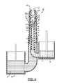
- FIG. 4is a cross sectional view of a dispensing tube assembly in accordance with this invention, showing the foam generator as fitted to the coaxial tubes.
- the dispensing tube assembly 10includes a first component delivery tube 12 ( FIG. 2 ) providing an axial passage 14 defining an axial flow path F 1 .
- the dispensing tube assembly 10also includes a second component delivery tube 16 ( FIG. 3 ), which surrounds the first component delivery tube 12 to define an annular passage 18 , defining an annular flow path F 2 .
- a foam generator 20is fitted to the coaxial first and second component delivery tubes 12 , 16 to complete the dispensing tube assembly 10 .
- the foam generator 20can be a separate element structured to fit onto coaxial tubes.
- a dispensing tube assembly in accordance with this inventionmight also be provided through the use of less or more individual components.
- a first component Sis advanced through the first component delivery tube 12 by an appropriate flow generator (e.g., a pump) from a first component source 22
- a second component Ais similarly advanced through the second component delivery tube 16 from a second component source 24
- the first component Sis soap
- the second component Ais air
- each of these componentsis advanced through its respective delivery tube 12 , 16 by any type of foam pump mechanism currently known or developed hereafter.
- the ultimate source for the air in such an embodimentis typically the atmosphere, while the soap is provided from a suitable container.
- a particular foam pump mechanism employing coaxial tubes to generate foam soapis disclosed in copending U.S. patent application Ser. No. 11/728,557, and this foam generator 20 could be readily employed to cap the coaxial tubes and generate the foam soap.
- the foam generator 20includes a body portion 26 having an axial extension 28 that is sized to fit intimately within the inside diameter of the second component delivery tube 16 .
- Four mounting arms 30extend axially from axial extension 28 to fit over the first component delivery tube 12 . More particularly, each arm 30 has an associated radial step 32 that rests on the end surface 34 of the first component delivery tube 12 , and an arm extension 33 that extends down the outer diameter of the first component delivery tube 12 .
- the mounting arms 30are each radially offset from neighboring mounting arms 30 by 90 degrees.
- the radial steps 32distance the end surface 34 from an axial path end plate 36 which defines an axial terminus for the axial flow path F 1 .
- the first component Sis therefore prevented from further travel along the axial flow path F 1 as it comes into contact with the axial path end plate 36 . Instead, the first component S must travel radially into the annular passage 18 , to flow along the annular flow path F 2 through the four premix apertures 38 ( FIGS. 2 and 4 ) that are formed between the end surface 34 , the end plate 36 , and neighboring steps 32 .
- the axial extension 28 of the body portion 26provides an annular flow path end plate 40 , which is a bottom radial surface 42 of the axial extension 28 , segmented by the mounting arms 30 .
- the annular flow path end plate 40defines an axial terminus for the annular passage 18 , and four post mix apertures 44 are formed between neighboring arms 30 and extend from the annular passage 18 to a post mix chamber 46 provided as a bore in the axial extension 28 .
- the annular flow path end plate 40defines an axial terminus for the annular passage 18 , such that components flowing along the annular flow path F 2 are forced through the post mix apertures 44 and into the post mix chamber 46 .
- annular premix chambers 48are defined in the annular passage 18 between the premix apertures 38 the post mix apertures 44 and the associated neighboring arms 30 . These areas are termed “annular premix chambers” because it is at these locations where the first component S and the second component A first begin to mix. They are termed “chambers” because, even though they do not have particular boundaries in some directions, the chamber volume can be appreciated from an understanding of the structure already disclosed and the flow pattern of the components.
- the premixture formed at the annular premix chambers 48is forced into the post mix chamber 46 through the post mix apertures 44 , and this premixture is advanced toward the outlet 50 of the foam generator 20 .
- a foam media 52is positioned in the foam generator 20 , between the post mix chamber 46 and the outlet 50 such that the premixture must pass through the foam media 52 before being dispensed at the outlet 50 .
- This foam media 52serves to homogenize the mixture of the first component S and second component A, and may be provided in the form of a mesh screen or sponge-like or open-celled foam.
- the foam media 52is sandwiched between an end cap 54 and the body portion 26 , with the end cap 54 connecting to the body portion 26 at a snap fit connection 56 .
- the heavier of the two fluidsbe chosen to travel the path described above for the first component S, and that the lighter fluid be chosen to travel the path described for the second component A.
- the heavier fluidis thus split and injected into the stream of the lighter fluid via the premix apertures 28 .
- the heavier fluidis also injected into the lighter fluid along a flow path that extends across the flow path of the lighter fluid, i.e., while the lighter fluid or, more broadly, the second component A is flowing axially, the heavier fluid or, more broadly, the first component S is caused to mix into that axial flow by being forced radially into that flow path.
- the difference in flow directionpromotes mixing.
- the extrusion of the two components through the post mix apertures 44also creates turbulent mixing, because the components are subjected to increased pressure as they travel through the restricted cross section passageways of the post mix apertures 44 , and thereafter expand into the larger volume of the post mix chamber.
- the present inventionprovides a dispensing tube assembly that substantially improves the art, particularly with respect to the mixing of soap and air to create a foam soap product.
Landscapes
- Containers And Packaging Bodies Having A Special Means To Remove Contents (AREA)
- Nozzles (AREA)
- Accessories For Mixers (AREA)
Abstract
Description
Claims (19)
Priority Applications (4)
| Application Number | Priority Date | Filing Date | Title |
|---|---|---|---|
| US12/287,877US8286836B2 (en) | 2008-10-14 | 2008-10-14 | Dispensing tube assembly and foam generator for coaxial tubes |
| CA2740769ACA2740769A1 (en) | 2008-10-14 | 2009-10-13 | Dispensing tube assembly and foam generator for coaxial tubes |
| PCT/US2009/060459WO2010045200A1 (en) | 2008-10-14 | 2009-10-13 | Dispensing tube assembly and foam generator for coaxial tubes |
| TW098134797ATWI488693B (en) | 2008-10-14 | 2009-10-14 | Dispensing tube assembly and foam generator for coaxial tubes |
Applications Claiming Priority (1)
| Application Number | Priority Date | Filing Date | Title |
|---|---|---|---|
| US12/287,877US8286836B2 (en) | 2008-10-14 | 2008-10-14 | Dispensing tube assembly and foam generator for coaxial tubes |
Publications (2)
| Publication Number | Publication Date |
|---|---|
| US20100089951A1 US20100089951A1 (en) | 2010-04-15 |
| US8286836B2true US8286836B2 (en) | 2012-10-16 |
Family
ID=41600459
Family Applications (1)
| Application Number | Title | Priority Date | Filing Date |
|---|---|---|---|
| US12/287,877Expired - Fee RelatedUS8286836B2 (en) | 2008-10-14 | 2008-10-14 | Dispensing tube assembly and foam generator for coaxial tubes |
Country Status (4)
| Country | Link |
|---|---|
| US (1) | US8286836B2 (en) |
| CA (1) | CA2740769A1 (en) |
| TW (1) | TWI488693B (en) |
| WO (1) | WO2010045200A1 (en) |
Cited By (4)
| Publication number | Priority date | Publication date | Assignee | Title |
|---|---|---|---|---|
| US20140097205A1 (en)* | 2012-10-04 | 2014-04-10 | Arminak & Associates, Llc | Mixing chamber for two fluid constituents |
| USD742016S1 (en)* | 2014-03-05 | 2015-10-27 | Wagner Spraytech Limited | Rounded air horn |
| US20160199805A1 (en)* | 2013-09-20 | 2016-07-14 | Spraying Systems Co. | High efficiency/low pressure catalytic cracking spray nozzle assembly |
| US10342934B2 (en)* | 2015-04-17 | 2019-07-09 | Smbure Co., Ltd. | Sprayer and spray control apparatus |
Families Citing this family (7)
| Publication number | Priority date | Publication date | Assignee | Title |
|---|---|---|---|---|
| US8544698B2 (en)* | 2007-03-26 | 2013-10-01 | Gojo Industries, Inc. | Foam soap dispenser with stationary dispensing tube |
| US9101952B2 (en)* | 2011-06-06 | 2015-08-11 | Gojo Industries, Inc. | Modular pump |
| NL2009084C2 (en)* | 2012-06-29 | 2013-12-31 | Rexam Airspray Nv | Foam dispensing assembly. |
| KR200475352Y1 (en)* | 2013-03-26 | 2014-11-26 | 펌텍코리아 (주) | Cosmetic container capable for mixing discharging in two contents |
| MY186715A (en) | 2014-10-02 | 2021-08-12 | Unilever Plc | Liquid dispenser with framed refill receiving bay |
| GB2586301B (en)* | 2020-04-07 | 2021-08-25 | Splash Tm Gmbh | Stable-Foam inhalation Device and Cartridge |
| US12364371B2 (en)* | 2022-02-01 | 2025-07-22 | Little Kids, Inc. | Soap foam generating machine |
Citations (27)
| Publication number | Priority date | Publication date | Assignee | Title |
|---|---|---|---|---|
| US708893A (en) | 1901-08-08 | 1902-09-09 | Charles Gustavus Lundholm | Burner for liquid fuels. |
| US982584A (en) | 1906-03-08 | 1911-01-24 | Window Glass Machine Co | Oil and gas burner. |
| US3361304A (en)* | 1966-02-25 | 1968-01-02 | Schering Corp | Medicament atomizer and foamer |
| US3531050A (en) | 1967-04-22 | 1970-09-29 | Ca Atomic Energy Ltd | Two-phase homogenizer |
| US3888420A (en) | 1973-11-16 | 1975-06-10 | Uni Mist | Positive-displacement mist lubricator |
| US4615467A (en) | 1985-07-24 | 1986-10-07 | Calmar, Inc. | Liquid foam dispenser |
| US4669665A (en) | 1984-10-11 | 1987-06-02 | Specialty Packaging Licensing Company | Nozzle |
| US4767060A (en) | 1987-06-05 | 1988-08-30 | Specialty Packaging Licensing Company | Nozzle |
| US5234167A (en) | 1989-11-16 | 1993-08-10 | Afa Products, Inc. | One-piece foamer nozzle |
| US5462208A (en) | 1994-08-01 | 1995-10-31 | The Procter & Gamble Company | Two-phase dispensing systems utilizing bellows pumps |
| US5544788A (en)* | 1993-02-17 | 1996-08-13 | Steiner Company, Inc. | Method of and apparatus for dispensing batches of soap lather |
| US5553785A (en)* | 1995-01-10 | 1996-09-10 | Spraying Systems Co. | Enhanced efficiency apparatus for atomizing and spraying liquid |
| US5647539A (en) | 1994-12-01 | 1997-07-15 | Calmar Inc. | Foamer nozzle assembly for trigger sprayer |
| US5732885A (en)* | 1994-10-07 | 1998-03-31 | Spraying Systems Co. | Internal mix air atomizing spray nozzle |
| WO1999049769A1 (en) | 1998-03-30 | 1999-10-07 | Sprintvest Corporation N.V. | Improved liquid dispenser for dispensing foam |
| US5984146A (en) | 1996-09-27 | 1999-11-16 | Kaufman; John G. | Dispenser having foamed output |
| US6042089A (en) | 1996-07-01 | 2000-03-28 | Klein; Christophe | Foam generating device |
| US6267301B1 (en)* | 1999-06-11 | 2001-07-31 | Spraying Systems Co. | Air atomizing nozzle assembly with improved air cap |
| US20010032892A1 (en) | 2000-01-31 | 2001-10-25 | Brooks David N. | Fire hose system having actively controllable multi-channel fire hose |
| WO2003095097A1 (en) | 2002-05-07 | 2003-11-20 | Spraying Systems Co. | Internal mix air atomizing spray nozzle assembly |
| US20040069807A1 (en) | 2000-11-23 | 2004-04-15 | Brouwer Markus Franciskus | Foam forming unit |
| US20050258192A1 (en)* | 2004-05-07 | 2005-11-24 | Matthews Shaun K | Method of producing foamed cleaser with suspended particles therein and a dispenser therefore |
| US6968776B2 (en) | 2001-07-11 | 2005-11-29 | Spidem S.P.A | Device for heating and emulsifying liquids, in particular drinks |
| US20060011655A1 (en) | 2004-07-14 | 2006-01-19 | Heiner Ophardt | Sink side touchless foam dispenser |
| US7066355B2 (en)* | 2004-06-25 | 2006-06-27 | Kimberly-Clark Worldwide, Inc. | Self-contained viscous liquid dispenser with a foaming pump |
| WO2008072949A2 (en) | 2006-12-11 | 2008-06-19 | Rexam Airspray N.V. | Foam- forming assembly, squeeze foamer and dispensing device |
| EP1974640A2 (en) | 2007-03-26 | 2008-10-01 | Kanfer, Joseph S. | Foam soap dispenser with stationary dispensing tube |
- 2008
- 2008-10-14USUS12/287,877patent/US8286836B2/ennot_activeExpired - Fee Related
- 2009
- 2009-10-13CACA2740769Apatent/CA2740769A1/ennot_activeAbandoned
- 2009-10-13WOPCT/US2009/060459patent/WO2010045200A1/enactiveApplication Filing
- 2009-10-14TWTW098134797Apatent/TWI488693B/ennot_activeIP Right Cessation
Patent Citations (31)
| Publication number | Priority date | Publication date | Assignee | Title |
|---|---|---|---|---|
| US708893A (en) | 1901-08-08 | 1902-09-09 | Charles Gustavus Lundholm | Burner for liquid fuels. |
| US982584A (en) | 1906-03-08 | 1911-01-24 | Window Glass Machine Co | Oil and gas burner. |
| US3361304A (en)* | 1966-02-25 | 1968-01-02 | Schering Corp | Medicament atomizer and foamer |
| US3531050A (en) | 1967-04-22 | 1970-09-29 | Ca Atomic Energy Ltd | Two-phase homogenizer |
| US3888420A (en) | 1973-11-16 | 1975-06-10 | Uni Mist | Positive-displacement mist lubricator |
| US4669665A (en) | 1984-10-11 | 1987-06-02 | Specialty Packaging Licensing Company | Nozzle |
| US4615467A (en) | 1985-07-24 | 1986-10-07 | Calmar, Inc. | Liquid foam dispenser |
| US4767060A (en) | 1987-06-05 | 1988-08-30 | Specialty Packaging Licensing Company | Nozzle |
| US5234167A (en) | 1989-11-16 | 1993-08-10 | Afa Products, Inc. | One-piece foamer nozzle |
| US5544788A (en)* | 1993-02-17 | 1996-08-13 | Steiner Company, Inc. | Method of and apparatus for dispensing batches of soap lather |
| US5462208A (en) | 1994-08-01 | 1995-10-31 | The Procter & Gamble Company | Two-phase dispensing systems utilizing bellows pumps |
| US5732885A (en)* | 1994-10-07 | 1998-03-31 | Spraying Systems Co. | Internal mix air atomizing spray nozzle |
| US5647539A (en) | 1994-12-01 | 1997-07-15 | Calmar Inc. | Foamer nozzle assembly for trigger sprayer |
| US5553785A (en)* | 1995-01-10 | 1996-09-10 | Spraying Systems Co. | Enhanced efficiency apparatus for atomizing and spraying liquid |
| US6042089A (en) | 1996-07-01 | 2000-03-28 | Klein; Christophe | Foam generating device |
| US5984146A (en) | 1996-09-27 | 1999-11-16 | Kaufman; John G. | Dispenser having foamed output |
| WO1999049769A1 (en) | 1998-03-30 | 1999-10-07 | Sprintvest Corporation N.V. | Improved liquid dispenser for dispensing foam |
| US6082586A (en)* | 1998-03-30 | 2000-07-04 | Deb Ip Limited | Liquid dispenser for dispensing foam |
| US6267301B1 (en)* | 1999-06-11 | 2001-07-31 | Spraying Systems Co. | Air atomizing nozzle assembly with improved air cap |
| US20010032892A1 (en) | 2000-01-31 | 2001-10-25 | Brooks David N. | Fire hose system having actively controllable multi-channel fire hose |
| US20040069807A1 (en) | 2000-11-23 | 2004-04-15 | Brouwer Markus Franciskus | Foam forming unit |
| US6968776B2 (en) | 2001-07-11 | 2005-11-29 | Spidem S.P.A | Device for heating and emulsifying liquids, in particular drinks |
| WO2003095097A1 (en) | 2002-05-07 | 2003-11-20 | Spraying Systems Co. | Internal mix air atomizing spray nozzle assembly |
| US20050258192A1 (en)* | 2004-05-07 | 2005-11-24 | Matthews Shaun K | Method of producing foamed cleaser with suspended particles therein and a dispenser therefore |
| US7066355B2 (en)* | 2004-06-25 | 2006-06-27 | Kimberly-Clark Worldwide, Inc. | Self-contained viscous liquid dispenser with a foaming pump |
| US20060011655A1 (en) | 2004-07-14 | 2006-01-19 | Heiner Ophardt | Sink side touchless foam dispenser |
| US7364053B2 (en) | 2004-07-14 | 2008-04-29 | Hygiene-Technik Inc. | Sink side touchless foam dispenser |
| US7455197B2 (en) | 2004-07-14 | 2008-11-25 | Gotohti.Com Inc. | Sink side touchless foam dispenser nozzle assembly |
| WO2008072949A2 (en) | 2006-12-11 | 2008-06-19 | Rexam Airspray N.V. | Foam- forming assembly, squeeze foamer and dispensing device |
| EP1974640A2 (en) | 2007-03-26 | 2008-10-01 | Kanfer, Joseph S. | Foam soap dispenser with stationary dispensing tube |
| US20080237266A1 (en)* | 2007-03-26 | 2008-10-02 | Ciavarella Nick E | Foam soap dispenser with stationary dispensing tube |
Non-Patent Citations (1)
| Title |
|---|
| International Preliminary Report on Patentability from International Application No. PCT/US2009/060459 dated Apr. 19, 2011. |
Cited By (6)
| Publication number | Priority date | Publication date | Assignee | Title |
|---|---|---|---|---|
| US20140097205A1 (en)* | 2012-10-04 | 2014-04-10 | Arminak & Associates, Llc | Mixing chamber for two fluid constituents |
| US9586217B2 (en)* | 2012-10-04 | 2017-03-07 | Arminak & Associates, Llc | Mixing chamber for two fluid constituents |
| US20160199805A1 (en)* | 2013-09-20 | 2016-07-14 | Spraying Systems Co. | High efficiency/low pressure catalytic cracking spray nozzle assembly |
| US10201794B2 (en)* | 2013-09-20 | 2019-02-12 | Spraying Systems Co. | High efficiency/low pressure catalytic cracking spray nozzle assembly |
| USD742016S1 (en)* | 2014-03-05 | 2015-10-27 | Wagner Spraytech Limited | Rounded air horn |
| US10342934B2 (en)* | 2015-04-17 | 2019-07-09 | Smbure Co., Ltd. | Sprayer and spray control apparatus |
Also Published As
| Publication number | Publication date |
|---|---|
| US20100089951A1 (en) | 2010-04-15 |
| CA2740769A1 (en) | 2010-04-22 |
| TWI488693B (en) | 2015-06-21 |
| TW201026398A (en) | 2010-07-16 |
| WO2010045200A1 (en) | 2010-04-22 |
Similar Documents
| Publication | Publication Date | Title |
|---|---|---|
| US8286836B2 (en) | Dispensing tube assembly and foam generator for coaxial tubes | |
| USRE49597E1 (en) | Valvular conduit | |
| CN102553747B (en) | The method of multiple component dispensing cartridge, contact between mixing nozzle and minimizing fluid | |
| AU2010249197B2 (en) | Foam soap generator | |
| US9579613B2 (en) | Foam-at-a-distance systems, foam generators and refill units | |
| US20070278247A1 (en) | Foam dispenser and method of making foam from more than one liquid | |
| JP2005263324A (en) | Two-component dispensing device | |
| JP5555069B2 (en) | Foam discharge container | |
| CN101492109A (en) | Foam pump with improved piston structure | |
| AU2004210295B2 (en) | Improved foam forming unit | |
| US20140097205A1 (en) | Mixing chamber for two fluid constituents | |
| JP3329809B2 (en) | Media ejection head | |
| US20120305272A1 (en) | Foam generating device for fire hoses | |
| BR0113227A (en) | Filling nozzle for dispensing a liquid into a container and container filling machine | |
| EP1663500B1 (en) | Foam nozzle | |
| TWI832540B (en) | Actuator for a dual pump dispensing system | |
| AU2014333607A1 (en) | Spray nozzle comprising a cyclone-like swirl chamber | |
| JP2006055829A (en) | Liquid diluting/mixing/feeding apparatus | |
| CN101380615A (en) | Nozzle structure |
Legal Events
| Date | Code | Title | Description |
|---|---|---|---|
| AS | Assignment | Owner name:GOJO INDUSTRIES, INC.,OHIO Free format text:ASSIGNMENT OF ASSIGNORS INTEREST;ASSIGNOR:YATES, JAMES M.;REEL/FRAME:021820/0599 Effective date:20081008 Owner name:GOJO INDUSTRIES, INC., OHIO Free format text:ASSIGNMENT OF ASSIGNORS INTEREST;ASSIGNOR:YATES, JAMES M.;REEL/FRAME:021820/0599 Effective date:20081008 | |
| AS | Assignment | Owner name:PNC BANK, NATIONAL ASSOCIATION, PENNSYLVANIA Free format text:SECURITY AGREEMENT;ASSIGNOR:GOJO INDUSTRIES, INC.;REEL/FRAME:025454/0001 Effective date:20101029 | |
| AS | Assignment | Owner name:STEEL CITY CAPITAL FUNDING, A DIVISION OF PNC BANK Free format text:SECURITY AGREEMENT;ASSIGNOR:GOJO INDUSTRIES, INC.;REEL/FRAME:025495/0678 Effective date:20101029 | |
| ZAAA | Notice of allowance and fees due | Free format text:ORIGINAL CODE: NOA | |
| ZAAB | Notice of allowance mailed | Free format text:ORIGINAL CODE: MN/=. | |
| AS | Assignment | Owner name:GOJO INDUSTRIES, INC., OHIO Free format text:RELEASE BY SECURED PARTY;ASSIGNOR:STEEL CITY CAPITAL FUNDING, A DIVISION OF PNC BANK, NATIONAL ASSOCIATION;REEL/FRAME:028575/0804 Effective date:20120713 | |
| STCF | Information on status: patent grant | Free format text:PATENTED CASE | |
| FEPP | Fee payment procedure | Free format text:PAYOR NUMBER ASSIGNED (ORIGINAL EVENT CODE: ASPN); ENTITY STATUS OF PATENT OWNER: LARGE ENTITY | |
| FEPP | Fee payment procedure | Free format text:PAYOR NUMBER ASSIGNED (ORIGINAL EVENT CODE: ASPN); ENTITY STATUS OF PATENT OWNER: LARGE ENTITY Free format text:PAYER NUMBER DE-ASSIGNED (ORIGINAL EVENT CODE: RMPN); ENTITY STATUS OF PATENT OWNER: LARGE ENTITY | |
| FPAY | Fee payment | Year of fee payment:4 | |
| MAFP | Maintenance fee payment | Free format text:PAYMENT OF MAINTENANCE FEE, 8TH YEAR, LARGE ENTITY (ORIGINAL EVENT CODE: M1552); ENTITY STATUS OF PATENT OWNER: LARGE ENTITY Year of fee payment:8 | |
| AS | Assignment | Owner name:PNC BANK, NATIONAL ASSOCIATION, PENNSYLVANIA Free format text:SECURITY INTEREST;ASSIGNOR:GOJO INDUSTRIES, INC.;REEL/FRAME:065369/0253 Effective date:20231026 | |
| AS | Assignment | Owner name:SILVER POINT FINANCE, LLC, AS COLLATERAL AGENT, CONNECTICUT Free format text:SECURITY INTEREST;ASSIGNOR:GOJO INDUSTRIES, INC.;REEL/FRAME:065382/0587 Effective date:20231026 | |
| FEPP | Fee payment procedure | Free format text:MAINTENANCE FEE REMINDER MAILED (ORIGINAL EVENT CODE: REM.); ENTITY STATUS OF PATENT OWNER: LARGE ENTITY | |
| LAPS | Lapse for failure to pay maintenance fees | Free format text:PATENT EXPIRED FOR FAILURE TO PAY MAINTENANCE FEES (ORIGINAL EVENT CODE: EXP.); ENTITY STATUS OF PATENT OWNER: LARGE ENTITY | |
| STCH | Information on status: patent discontinuation | Free format text:PATENT EXPIRED DUE TO NONPAYMENT OF MAINTENANCE FEES UNDER 37 CFR 1.362 | |
| FP | Lapsed due to failure to pay maintenance fee | Effective date:20241016 |