US8286740B2 - Hybrid working machine - Google Patents
Hybrid working machineDownload PDFInfo
- Publication number
- US8286740B2 US8286740B2US12/581,299US58129909AUS8286740B2US 8286740 B2US8286740 B2US 8286740B2US 58129909 AUS58129909 AUS 58129909AUS 8286740 B2US8286740 B2US 8286740B2
- Authority
- US
- United States
- Prior art keywords
- generator
- voltage
- storage device
- rotation motor
- electric
- Prior art date
- Legal status (The legal status is an assumption and is not a legal conclusion. Google has not performed a legal analysis and makes no representation as to the accuracy of the status listed.)
- Expired - Fee Related, expires
Links
Images


Classifications
- B—PERFORMING OPERATIONS; TRANSPORTING
- B60—VEHICLES IN GENERAL
- B60W—CONJOINT CONTROL OF VEHICLE SUB-UNITS OF DIFFERENT TYPE OR DIFFERENT FUNCTION; CONTROL SYSTEMS SPECIALLY ADAPTED FOR HYBRID VEHICLES; ROAD VEHICLE DRIVE CONTROL SYSTEMS FOR PURPOSES NOT RELATED TO THE CONTROL OF A PARTICULAR SUB-UNIT
- B60W20/00—Control systems specially adapted for hybrid vehicles
- B60W20/50—Control strategies for responding to system failures, e.g. for fault diagnosis, failsafe operation or limp mode
- B—PERFORMING OPERATIONS; TRANSPORTING
- B60—VEHICLES IN GENERAL
- B60K—ARRANGEMENT OR MOUNTING OF PROPULSION UNITS OR OF TRANSMISSIONS IN VEHICLES; ARRANGEMENT OR MOUNTING OF PLURAL DIVERSE PRIME-MOVERS IN VEHICLES; AUXILIARY DRIVES FOR VEHICLES; INSTRUMENTATION OR DASHBOARDS FOR VEHICLES; ARRANGEMENTS IN CONNECTION WITH COOLING, AIR INTAKE, GAS EXHAUST OR FUEL SUPPLY OF PROPULSION UNITS IN VEHICLES
- B60K6/00—Arrangement or mounting of plural diverse prime-movers for mutual or common propulsion, e.g. hybrid propulsion systems comprising electric motors and internal combustion engines
- B60K6/20—Arrangement or mounting of plural diverse prime-movers for mutual or common propulsion, e.g. hybrid propulsion systems comprising electric motors and internal combustion engines the prime-movers consisting of electric motors and internal combustion engines, e.g. HEVs
- B60K6/42—Arrangement or mounting of plural diverse prime-movers for mutual or common propulsion, e.g. hybrid propulsion systems comprising electric motors and internal combustion engines the prime-movers consisting of electric motors and internal combustion engines, e.g. HEVs characterised by the architecture of the hybrid electric vehicle
- B60K6/46—Series type
- B—PERFORMING OPERATIONS; TRANSPORTING
- B60—VEHICLES IN GENERAL
- B60L—PROPULSION OF ELECTRICALLY-PROPELLED VEHICLES; SUPPLYING ELECTRIC POWER FOR AUXILIARY EQUIPMENT OF ELECTRICALLY-PROPELLED VEHICLES; ELECTRODYNAMIC BRAKE SYSTEMS FOR VEHICLES IN GENERAL; MAGNETIC SUSPENSION OR LEVITATION FOR VEHICLES; MONITORING OPERATING VARIABLES OF ELECTRICALLY-PROPELLED VEHICLES; ELECTRIC SAFETY DEVICES FOR ELECTRICALLY-PROPELLED VEHICLES
- B60L1/00—Supplying electric power to auxiliary equipment of vehicles
- B60L1/003—Supplying electric power to auxiliary equipment of vehicles to auxiliary motors, e.g. for pumps, compressors
- B—PERFORMING OPERATIONS; TRANSPORTING
- B60—VEHICLES IN GENERAL
- B60L—PROPULSION OF ELECTRICALLY-PROPELLED VEHICLES; SUPPLYING ELECTRIC POWER FOR AUXILIARY EQUIPMENT OF ELECTRICALLY-PROPELLED VEHICLES; ELECTRODYNAMIC BRAKE SYSTEMS FOR VEHICLES IN GENERAL; MAGNETIC SUSPENSION OR LEVITATION FOR VEHICLES; MONITORING OPERATING VARIABLES OF ELECTRICALLY-PROPELLED VEHICLES; ELECTRIC SAFETY DEVICES FOR ELECTRICALLY-PROPELLED VEHICLES
- B60L1/00—Supplying electric power to auxiliary equipment of vehicles
- B60L1/20—Energy regeneration from auxiliary equipment
- B—PERFORMING OPERATIONS; TRANSPORTING
- B60—VEHICLES IN GENERAL
- B60L—PROPULSION OF ELECTRICALLY-PROPELLED VEHICLES; SUPPLYING ELECTRIC POWER FOR AUXILIARY EQUIPMENT OF ELECTRICALLY-PROPELLED VEHICLES; ELECTRODYNAMIC BRAKE SYSTEMS FOR VEHICLES IN GENERAL; MAGNETIC SUSPENSION OR LEVITATION FOR VEHICLES; MONITORING OPERATING VARIABLES OF ELECTRICALLY-PROPELLED VEHICLES; ELECTRIC SAFETY DEVICES FOR ELECTRICALLY-PROPELLED VEHICLES
- B60L50/00—Electric propulsion with power supplied within the vehicle
- B60L50/50—Electric propulsion with power supplied within the vehicle using propulsion power supplied by batteries or fuel cells
- B60L50/60—Electric propulsion with power supplied within the vehicle using propulsion power supplied by batteries or fuel cells using power supplied by batteries
- B60L50/61—Electric propulsion with power supplied within the vehicle using propulsion power supplied by batteries or fuel cells using power supplied by batteries by batteries charged by engine-driven generators, e.g. series hybrid electric vehicles
- B—PERFORMING OPERATIONS; TRANSPORTING
- B60—VEHICLES IN GENERAL
- B60L—PROPULSION OF ELECTRICALLY-PROPELLED VEHICLES; SUPPLYING ELECTRIC POWER FOR AUXILIARY EQUIPMENT OF ELECTRICALLY-PROPELLED VEHICLES; ELECTRODYNAMIC BRAKE SYSTEMS FOR VEHICLES IN GENERAL; MAGNETIC SUSPENSION OR LEVITATION FOR VEHICLES; MONITORING OPERATING VARIABLES OF ELECTRICALLY-PROPELLED VEHICLES; ELECTRIC SAFETY DEVICES FOR ELECTRICALLY-PROPELLED VEHICLES
- B60L7/00—Electrodynamic brake systems for vehicles in general
- B60L7/02—Dynamic electric resistor braking
- B—PERFORMING OPERATIONS; TRANSPORTING
- B60—VEHICLES IN GENERAL
- B60L—PROPULSION OF ELECTRICALLY-PROPELLED VEHICLES; SUPPLYING ELECTRIC POWER FOR AUXILIARY EQUIPMENT OF ELECTRICALLY-PROPELLED VEHICLES; ELECTRODYNAMIC BRAKE SYSTEMS FOR VEHICLES IN GENERAL; MAGNETIC SUSPENSION OR LEVITATION FOR VEHICLES; MONITORING OPERATING VARIABLES OF ELECTRICALLY-PROPELLED VEHICLES; ELECTRIC SAFETY DEVICES FOR ELECTRICALLY-PROPELLED VEHICLES
- B60L7/00—Electrodynamic brake systems for vehicles in general
- B60L7/10—Dynamic electric regenerative braking
- B—PERFORMING OPERATIONS; TRANSPORTING
- B60—VEHICLES IN GENERAL
- B60W—CONJOINT CONTROL OF VEHICLE SUB-UNITS OF DIFFERENT TYPE OR DIFFERENT FUNCTION; CONTROL SYSTEMS SPECIALLY ADAPTED FOR HYBRID VEHICLES; ROAD VEHICLE DRIVE CONTROL SYSTEMS FOR PURPOSES NOT RELATED TO THE CONTROL OF A PARTICULAR SUB-UNIT
- B60W10/00—Conjoint control of vehicle sub-units of different type or different function
- B60W10/04—Conjoint control of vehicle sub-units of different type or different function including control of propulsion units
- B60W10/06—Conjoint control of vehicle sub-units of different type or different function including control of propulsion units including control of combustion engines
- B—PERFORMING OPERATIONS; TRANSPORTING
- B60—VEHICLES IN GENERAL
- B60W—CONJOINT CONTROL OF VEHICLE SUB-UNITS OF DIFFERENT TYPE OR DIFFERENT FUNCTION; CONTROL SYSTEMS SPECIALLY ADAPTED FOR HYBRID VEHICLES; ROAD VEHICLE DRIVE CONTROL SYSTEMS FOR PURPOSES NOT RELATED TO THE CONTROL OF A PARTICULAR SUB-UNIT
- B60W10/00—Conjoint control of vehicle sub-units of different type or different function
- B60W10/04—Conjoint control of vehicle sub-units of different type or different function including control of propulsion units
- B60W10/08—Conjoint control of vehicle sub-units of different type or different function including control of propulsion units including control of electric propulsion units, e.g. motors or generators
- B—PERFORMING OPERATIONS; TRANSPORTING
- B60—VEHICLES IN GENERAL
- B60W—CONJOINT CONTROL OF VEHICLE SUB-UNITS OF DIFFERENT TYPE OR DIFFERENT FUNCTION; CONTROL SYSTEMS SPECIALLY ADAPTED FOR HYBRID VEHICLES; ROAD VEHICLE DRIVE CONTROL SYSTEMS FOR PURPOSES NOT RELATED TO THE CONTROL OF A PARTICULAR SUB-UNIT
- B60W10/00—Conjoint control of vehicle sub-units of different type or different function
- B60W10/24—Conjoint control of vehicle sub-units of different type or different function including control of energy storage means
- B60W10/26—Conjoint control of vehicle sub-units of different type or different function including control of energy storage means for electrical energy, e.g. batteries or capacitors
- B—PERFORMING OPERATIONS; TRANSPORTING
- B60—VEHICLES IN GENERAL
- B60W—CONJOINT CONTROL OF VEHICLE SUB-UNITS OF DIFFERENT TYPE OR DIFFERENT FUNCTION; CONTROL SYSTEMS SPECIALLY ADAPTED FOR HYBRID VEHICLES; ROAD VEHICLE DRIVE CONTROL SYSTEMS FOR PURPOSES NOT RELATED TO THE CONTROL OF A PARTICULAR SUB-UNIT
- B60W20/00—Control systems specially adapted for hybrid vehicles
- E—FIXED CONSTRUCTIONS
- E02—HYDRAULIC ENGINEERING; FOUNDATIONS; SOIL SHIFTING
- E02F—DREDGING; SOIL-SHIFTING
- E02F9/00—Component parts of dredgers or soil-shifting machines, not restricted to one of the kinds covered by groups E02F3/00 - E02F7/00
- E02F9/08—Superstructures; Supports for superstructures
- E02F9/10—Supports for movable superstructures mounted on travelling or walking gears or on other superstructures
- E02F9/12—Slewing or traversing gears
- E02F9/121—Turntables, i.e. structure rotatable about 360°
- E02F9/123—Drives or control devices specially adapted therefor
- E—FIXED CONSTRUCTIONS
- E02—HYDRAULIC ENGINEERING; FOUNDATIONS; SOIL SHIFTING
- E02F—DREDGING; SOIL-SHIFTING
- E02F9/00—Component parts of dredgers or soil-shifting machines, not restricted to one of the kinds covered by groups E02F3/00 - E02F7/00
- E02F9/20—Drives; Control devices
- E02F9/2058—Electric or electro-mechanical or mechanical control devices of vehicle sub-units
- E02F9/2062—Control of propulsion units
- E02F9/2075—Control of propulsion units of the hybrid type
- E—FIXED CONSTRUCTIONS
- E02—HYDRAULIC ENGINEERING; FOUNDATIONS; SOIL SHIFTING
- E02F—DREDGING; SOIL-SHIFTING
- E02F9/00—Component parts of dredgers or soil-shifting machines, not restricted to one of the kinds covered by groups E02F3/00 - E02F7/00
- E02F9/20—Drives; Control devices
- E02F9/2058—Electric or electro-mechanical or mechanical control devices of vehicle sub-units
- E02F9/2091—Control of energy storage means for electrical energy, e.g. battery or capacitors
- B—PERFORMING OPERATIONS; TRANSPORTING
- B60—VEHICLES IN GENERAL
- B60L—PROPULSION OF ELECTRICALLY-PROPELLED VEHICLES; SUPPLYING ELECTRIC POWER FOR AUXILIARY EQUIPMENT OF ELECTRICALLY-PROPELLED VEHICLES; ELECTRODYNAMIC BRAKE SYSTEMS FOR VEHICLES IN GENERAL; MAGNETIC SUSPENSION OR LEVITATION FOR VEHICLES; MONITORING OPERATING VARIABLES OF ELECTRICALLY-PROPELLED VEHICLES; ELECTRIC SAFETY DEVICES FOR ELECTRICALLY-PROPELLED VEHICLES
- B60L2200/00—Type of vehicles
- B60L2200/40—Working vehicles
- B—PERFORMING OPERATIONS; TRANSPORTING
- B60—VEHICLES IN GENERAL
- B60W—CONJOINT CONTROL OF VEHICLE SUB-UNITS OF DIFFERENT TYPE OR DIFFERENT FUNCTION; CONTROL SYSTEMS SPECIALLY ADAPTED FOR HYBRID VEHICLES; ROAD VEHICLE DRIVE CONTROL SYSTEMS FOR PURPOSES NOT RELATED TO THE CONTROL OF A PARTICULAR SUB-UNIT
- B60W50/00—Details of control systems for road vehicle drive control not related to the control of a particular sub-unit, e.g. process diagnostic or vehicle driver interfaces
- B60W50/02—Ensuring safety in case of control system failures, e.g. by diagnosing, circumventing or fixing failures
- B60W50/029—Adapting to failures or work around with other constraints, e.g. circumvention by avoiding use of failed parts
- B60W2050/0297—Control Giving priority to different actuators or systems
- B—PERFORMING OPERATIONS; TRANSPORTING
- B60—VEHICLES IN GENERAL
- B60W—CONJOINT CONTROL OF VEHICLE SUB-UNITS OF DIFFERENT TYPE OR DIFFERENT FUNCTION; CONTROL SYSTEMS SPECIALLY ADAPTED FOR HYBRID VEHICLES; ROAD VEHICLE DRIVE CONTROL SYSTEMS FOR PURPOSES NOT RELATED TO THE CONTROL OF A PARTICULAR SUB-UNIT
- B60W2300/00—Indexing codes relating to the type of vehicle
- B60W2300/17—Construction vehicles, e.g. graders, excavators
- B—PERFORMING OPERATIONS; TRANSPORTING
- B60—VEHICLES IN GENERAL
- B60W—CONJOINT CONTROL OF VEHICLE SUB-UNITS OF DIFFERENT TYPE OR DIFFERENT FUNCTION; CONTROL SYSTEMS SPECIALLY ADAPTED FOR HYBRID VEHICLES; ROAD VEHICLE DRIVE CONTROL SYSTEMS FOR PURPOSES NOT RELATED TO THE CONTROL OF A PARTICULAR SUB-UNIT
- B60W2510/00—Input parameters relating to a particular sub-units
- B60W2510/24—Energy storage means
- B60W2510/242—Energy storage means for electrical energy
- B60W2510/244—Charge state
- B—PERFORMING OPERATIONS; TRANSPORTING
- B60—VEHICLES IN GENERAL
- B60Y—INDEXING SCHEME RELATING TO ASPECTS CROSS-CUTTING VEHICLE TECHNOLOGY
- B60Y2200/00—Type of vehicle
- B60Y2200/40—Special vehicles
- B60Y2200/41—Construction vehicles, e.g. graders, excavators
- B60Y2200/412—Excavators
- Y—GENERAL TAGGING OF NEW TECHNOLOGICAL DEVELOPMENTS; GENERAL TAGGING OF CROSS-SECTIONAL TECHNOLOGIES SPANNING OVER SEVERAL SECTIONS OF THE IPC; TECHNICAL SUBJECTS COVERED BY FORMER USPC CROSS-REFERENCE ART COLLECTIONS [XRACs] AND DIGESTS
- Y02—TECHNOLOGIES OR APPLICATIONS FOR MITIGATION OR ADAPTATION AGAINST CLIMATE CHANGE
- Y02T—CLIMATE CHANGE MITIGATION TECHNOLOGIES RELATED TO TRANSPORTATION
- Y02T10/00—Road transport of goods or passengers
- Y02T10/60—Other road transportation technologies with climate change mitigation effect
- Y02T10/62—Hybrid vehicles
- Y—GENERAL TAGGING OF NEW TECHNOLOGICAL DEVELOPMENTS; GENERAL TAGGING OF CROSS-SECTIONAL TECHNOLOGIES SPANNING OVER SEVERAL SECTIONS OF THE IPC; TECHNICAL SUBJECTS COVERED BY FORMER USPC CROSS-REFERENCE ART COLLECTIONS [XRACs] AND DIGESTS
- Y02—TECHNOLOGIES OR APPLICATIONS FOR MITIGATION OR ADAPTATION AGAINST CLIMATE CHANGE
- Y02T—CLIMATE CHANGE MITIGATION TECHNOLOGIES RELATED TO TRANSPORTATION
- Y02T10/00—Road transport of goods or passengers
- Y02T10/60—Other road transportation technologies with climate change mitigation effect
- Y02T10/70—Energy storage systems for electromobility, e.g. batteries
- Y—GENERAL TAGGING OF NEW TECHNOLOGICAL DEVELOPMENTS; GENERAL TAGGING OF CROSS-SECTIONAL TECHNOLOGIES SPANNING OVER SEVERAL SECTIONS OF THE IPC; TECHNICAL SUBJECTS COVERED BY FORMER USPC CROSS-REFERENCE ART COLLECTIONS [XRACs] AND DIGESTS
- Y02—TECHNOLOGIES OR APPLICATIONS FOR MITIGATION OR ADAPTATION AGAINST CLIMATE CHANGE
- Y02T—CLIMATE CHANGE MITIGATION TECHNOLOGIES RELATED TO TRANSPORTATION
- Y02T10/00—Road transport of goods or passengers
- Y02T10/60—Other road transportation technologies with climate change mitigation effect
- Y02T10/7072—Electromobility specific charging systems or methods for batteries, ultracapacitors, supercapacitors or double-layer capacitors
Definitions
- the present inventionrelates to a hybrid working machine that uses both engine power and electric power.
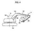
- an excavatorincludes a crawler-type lower traveling structure 101 and an upper rotating structure 102 rotatably mounted, around a vertical shaft O, on the lower traveling structure 101 .
- a working attachment Ais mounted on the upper rotating structure 102 .
- the working attachment Aincludes a boom 103 capable of moving up and down, an arm 104 attached to the tip of the boom 103 , a bucket 105 attached to the tip of the arm 104 , and cylinders 106 , 107 , and 108 that are hydraulic actuators for driving the boom 103 , the arm 104 , and the bucket 105 , respectively.
- a rotation hydraulic motoris used as a rotation actuator for rotating the upper rotating structure 102 .
- a rotation motoris used as the rotation actuator.
- a hydraulic pump and a generatorare driven by using an engine as a power source, and hydraulic actuators are driven by the hydraulic pump.
- a rotation motoris driven by the generator and an electric storage device that is charged with power output from the generator (See Japanese Unexamined Patent Application Publication Nos. 2000-283107 and 10-42587).
- the electric storage devicemay break down due to a failure in a relay, and may become unusable as a power source.
- a hybrid working machineincludes the following elements: an engine serving as a power source; a hydraulic pump serving as a hydraulic power source of a hydraulic actuator, the hydraulic pump being driven by the engine; a generator driven by the engine; an electric storage device that is charged with electric power generated by the generator; a rotation motor serving as a driving source of a rotating structure, the rotation motor being driven by the generator and the electric storage device; an electric-storage-device breakdown detector that detects that the electric storage device is unusable; and a controller unit that controls the generator and the rotation motor.
- the controller unitWhen it is detected by the electric-storage-device breakdown detector that the electric storage device is unusable, the controller unit is configured to perform emergency evacuation control that suppresses the power consumption of the rotation motor to be less than or equal to the power generation of the generator while maintaining voltage of a direct current bus greater than or equal to a normal operation voltage of a control system of the hybrid working machine.
- the regenerative power generated when the rotation speed is decreasingis stored in the electric storage device.
- the electric storage device becomes unusablethere will be no storage device for the regenerative power, and a regenerative brake operation may not be normally performed.
- the hybrid working machinefurther include a regenerative resistor that consumes regenerative power when the rotation motor is performing a regenerative operation; and a regenerative-resistor controller that controls the regenerative resistor.
- a regenerative resistorthat consumes regenerative power when the rotation motor is performing a regenerative operation
- a regenerative-resistor controllerthat controls the regenerative resistor.
- the hybrid working machinefurther include a bus voltage detector that detects the voltage of the direct current bus.
- the electric-storage-device breakdown detectormay detect that the electric storage device is unusable when the bus voltage detected by the bus voltage detector at start-up in a state in which the electric storage device is connected to the direct current bus is less than a set value.
- the voltage of the direct current buswhich directly indicates the state of the electric storage device, is detected to determine whether the electric storage device is unusable. Therefore, not only the breakdown of the electric storage device itself, but also the unusable state of the electric storage device due to other reasons can certainly be detected.
- FIG. 1is a block diagram of a hybrid excavator according to an embodiment of the present invention
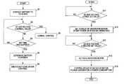
- FIG. 2is a flowchart illustrating a control switching flow of the excavator
- FIG. 3is a flowchart illustrating the flow of emergency evacuation control of the excavator.
- FIG. 4is a schematic side view of the excavator.
- a hybrid excavatorwill be described as embodiments of the present invention.
- FIG. 1is a block diagram of a drive system and a control system.
- a generator motor 2that performs both a generator operation and a motor operation and a hydraulic pump 3 are connected to an engine 1 serving as a power source.
- the generator motor 2 and the hydraulic pump 3are driven by the engine 1 .
- a boom cylinder and other hydraulic actuators(which are collectively given the reference numeral 5 ) are connected to the hydraulic pump 3 via a hydraulic circuit 4 including control valves (not shown).
- the hydraulic actuators 5are driven by pressure oil supplied from the hydraulic pump 3 .
- a rotation motor 8is connected to the generator motor 2 via a generator motor inverter 6 and a rotation motor inverter 7 constituting a controller unit.
- a battery (electric storage device) 11is connected via a battery connecting circuit 10 to DC buses 9 a and 9 b connecting the two inverters 6 and 7 .
- the rotation motor 8is driven by using the generator motor 2 and the battery 11 as a power source.
- a regenerative resistor circuit 12that performs a regenerative brake operation by consuming regenerative power when the rotation speed is decreasing is connected in parallel with the battery 11 to the DC buses 9 a and 9 b . Also, a regenerative resistor controller 13 controls the regenerative resistance of the regenerative resistor circuit 12 .
- main power source 11electric components such as a control system and a starter motor and an auxiliary battery serving as a power source of a working light (not shown) are provided as auxiliary power sources.
- a drive circuit and a battery circuit of the rotation motor 8are indicated by bold lines so that they can be distinguished from other circuits.
- the hybrid excavatorfurther includes, in addition to the foregoing basic structure, a voltage sensor 14 that detects the voltage of the DC buses 9 a and 9 b , a breakdown detector 15 , and a generator motor controller 16 and a rotation motor controller 17 constituting a controller unit.
- the breakdown detector 15determines whether the battery 11 is broken (unusable) on the basis of whether the voltage of the DC buses 9 a and 9 b , which is detected by the voltage sensor 14 at the time the system is started (at the time the key is switched on), is greater than or equal to a normal battery voltage (e.g., 150 V).
- a normal battery voltagee.g. 150 V.
- FIG. 2illustrates the flow of switching battery control between normal control and emergency evacuation control
- FIG. 3illustrates the flow of emergency evacuation control
- step S 1when the system is started by switching on the key, in step S 1 , the battery connecting circuit 10 connects the battery 11 to the DC buses 9 a and 9 b .
- step S 2it is determined whether the detected voltage is greater than or equal to normal value (e.g., 150 V) indicating that the battery 11 is normal.
- normal valuee.g. 150 V
- step S 2 and S 3When the detected voltage is less the normal value even after a set time has elapsed since the battery connection (steps S 2 and S 3 ), it is determined that the battery 11 is broken, and the control is switched to emergency evacuation control (steps S 4 and S 5 ).
- step S 6when the detected voltage is greater than or equal to the normal value (YES in step S 2 ), it is determined that the battery 11 is working well, and the control proceeds to normal control (step S 6 ).
- step S 11when the engine 1 is started by the starter motor, in step S 11 , it is determined whether the voltage of the DC buses 9 a and 9 b is greater than or equal to a first set value.
- the first set valueis a value that is approximately the electromotive force of the generator motor 2 .
- the generator motor inverter 6sets the torque of the generator motor 2 , and a power generating operation of the generator motor 2 is started.
- the torque of the generator motor 2is set and controlled so that the voltage of the DC buses 9 a and 9 b will be maintained greater than or equal to a normal operation voltage (second set value; e.g., 300 V) of the entire system when the battery 11 is working well.
- second set valuee.g. 300 V
- step S 13it is determined whether the voltage of the DC buses 9 a and 9 b has become greater than or equal to the second set value.
- step S 13the rotation motor 8 is activated by the rotation motor controller 17 , and the speed of the rotation motor 8 is controlled while regulating the speed or power (speed ⁇ torque) of the rotation motor 8 in accordance with the amount of operation of a rotation operating lever (not shown) so that the power generation of the generator motor 2 will become greater than or equal to the power consumption of the rotation motor 8 (step S 15 ).
- the regenerative power generated in the rotation motor 8 when the rotation speed is decreasingis fed to the regenerative resistor circuit 12 via the rotation motor inverter 7 and is consumed in the regenerative resistor circuit 12 .
- a regenerative brake operation similar to that when the battery 11 is working wellcan be ensured.
- the so-called parallel hybrid structure in which both the generator motor 2 and the hydraulic pump 3 are simultaneously driven by the engine 1has been described by way of example.
- the present inventionis also applicable to the case of a so-called series hybrid structure in which a generator is driven by an engine, and a rotation motor and a pump motor are driven by the power generated by the generator. Also in this case, advantageous effects similar to those achieved in the above-described embodiment can be achieved.
- the generator motor 2performing both a generator operation and a motor operation is used.
- a generator and a motor that are separated from each othermay be used as a power unit.
- the present inventionis not limited to a hybrid excavator, and the present invention is also applicable to a crusher, a wrecker, or the like that is configured by using an excavator.
Landscapes
- Engineering & Computer Science (AREA)
- Transportation (AREA)
- Mechanical Engineering (AREA)
- Power Engineering (AREA)
- Chemical & Material Sciences (AREA)
- Combustion & Propulsion (AREA)
- Structural Engineering (AREA)
- General Engineering & Computer Science (AREA)
- Civil Engineering (AREA)
- Mining & Mineral Resources (AREA)
- Automation & Control Theory (AREA)
- General Health & Medical Sciences (AREA)
- Biomedical Technology (AREA)
- Health & Medical Sciences (AREA)
- Sustainable Energy (AREA)
- Sustainable Development (AREA)
- Life Sciences & Earth Sciences (AREA)
- Operation Control Of Excavators (AREA)
- Control Of Ac Motors In General (AREA)
Abstract
Description
- (i) Because the electric storage device, which is the power charging destination of the power output from the generator and which is one of the power sources of the rotation motor, becomes unusable, the voltage of a direct current (DC) bus connecting the generator (generator inverter) and the rotation motor (rotation motor generator) becomes unstable;
- (ii) The power generation of the generator becomes insufficient for the power consumption of the rotation motor; and
- (iii) As the engine load becomes greater, the output of the hydraulic pump becomes smaller.
Accordingly, both the rotation and the hydraulic operation become unstable.
Claims (3)
Applications Claiming Priority (2)
| Application Number | Priority Date | Filing Date | Title |
|---|---|---|---|
| JP2008-278785 | 2008-10-29 | ||
| JP2008278785AJP4609567B2 (en) | 2008-10-29 | 2008-10-29 | Hybrid work machine |
Publications (2)
| Publication Number | Publication Date |
|---|---|
| US20100102763A1 US20100102763A1 (en) | 2010-04-29 |
| US8286740B2true US8286740B2 (en) | 2012-10-16 |
Family
ID=41651450
Family Applications (1)
| Application Number | Title | Priority Date | Filing Date |
|---|---|---|---|
| US12/581,299Expired - Fee RelatedUS8286740B2 (en) | 2008-10-29 | 2009-10-19 | Hybrid working machine |
Country Status (4)
| Country | Link |
|---|---|
| US (1) | US8286740B2 (en) |
| EP (1) | EP2181905B1 (en) |
| JP (1) | JP4609567B2 (en) |
| CN (1) | CN101725163B (en) |
Cited By (6)
| Publication number | Priority date | Publication date | Assignee | Title |
|---|---|---|---|---|
| US20140062096A1 (en)* | 2012-09-06 | 2014-03-06 | Kobelco Construction Machinery Co., Ltd. | Hybrid construction machine |
| US20150086315A1 (en)* | 2013-09-24 | 2015-03-26 | Kobelco Construction Machinery Co., Ltd. | Hybrid construction machine |
| US9764634B2 (en) | 2015-05-28 | 2017-09-19 | Joy Global Longview Operations Llc | Mining machine and energy storage system for same |
| US20170291501A1 (en)* | 2014-10-14 | 2017-10-12 | Hitachi Construction Machinery Co., Ltd. | Hybrid Construction Machinery |
| US10100493B2 (en) | 2014-03-31 | 2018-10-16 | Sumitomo (S.H.I.) Construction Machinery Co., Ltd. | Shovel |
| US10132335B2 (en) | 2012-09-21 | 2018-11-20 | Joy Global Surface Mining Inc | Energy management system for machinery performing a predictable work cycle |
Families Citing this family (32)
| Publication number | Priority date | Publication date | Assignee | Title |
|---|---|---|---|---|
| JP5703587B2 (en) | 2010-04-14 | 2015-04-22 | コベルコ建機株式会社 | Hybrid work machine |
| JP5353849B2 (en)* | 2010-09-24 | 2013-11-27 | コベルコ建機株式会社 | Construction machinery |
| CN102094433B (en)* | 2010-12-10 | 2012-02-08 | 广西大学 | A Hybrid Drive Controllable Excavation Mechanism |
| JP5699598B2 (en)* | 2010-12-28 | 2015-04-15 | コベルコ建機株式会社 | Construction machinery |
| JP2012154092A (en)* | 2011-01-26 | 2012-08-16 | Kobelco Contstruction Machinery Ltd | Hybrid construction machine |
| JP5747533B2 (en)* | 2011-02-02 | 2015-07-15 | コベルコ建機株式会社 | Swivel work machine |
| JP5356427B2 (en)* | 2011-02-03 | 2013-12-04 | 日立建機株式会社 | Hybrid construction machine |
| JP5509433B2 (en)* | 2011-03-22 | 2014-06-04 | 日立建機株式会社 | Hybrid construction machine and auxiliary control device used therefor |
| CN102251545B (en)* | 2011-04-28 | 2013-12-18 | 上海三一重机有限公司 | Electrical control system for electric excavator |
| JP5925782B2 (en)* | 2011-08-09 | 2016-05-25 | 住友建機株式会社 | Slewing drive |
| JP5778570B2 (en)* | 2011-12-20 | 2015-09-16 | 日立建機株式会社 | Construction machinery |
| CN102490583B (en)* | 2012-01-05 | 2014-01-15 | 三一汽车起重机械有限公司 | Hybrid power system for hydraulic system and engineering machine |
| JP5928065B2 (en)* | 2012-03-27 | 2016-06-01 | コベルコ建機株式会社 | Control device and construction machine equipped with the same |
| US9725880B2 (en)* | 2012-06-08 | 2017-08-08 | Volvo Construction Equipment Ab | Apparatus for controlling a cascaded hybrid construction machine system and a method therefor |
| CN102826000B (en)* | 2012-08-17 | 2016-04-06 | 湖南三一港口设备有限公司 | Vehicle hybrid system and container stacking machine |
| CN102877495B (en)* | 2012-09-11 | 2014-12-03 | 华南理工大学 | Hybrid power system for recovering potential energy of movable arm of excavating machine |
| JP6009339B2 (en)* | 2012-12-11 | 2016-10-19 | ナブテスコ株式会社 | Control device for hybrid construction machine |
| CN103863088A (en)* | 2012-12-15 | 2014-06-18 | 陈梦企 | Driving system for tandem double-dynamic engineering machine |
| JP6036344B2 (en)* | 2013-01-30 | 2016-11-30 | コベルコ建機株式会社 | Hybrid construction machinery |
| EP3015607B1 (en)* | 2013-06-26 | 2018-12-12 | Hitachi Construction Machinery Co., Ltd. | Hybrid work machine |
| US10125556B1 (en) | 2013-07-02 | 2018-11-13 | Abe B Erdman, Jr. | Pipe fitting assembly apparatus |
| US9528331B1 (en)* | 2013-07-02 | 2016-12-27 | Abe B Erdman, Jr. | Pipe fitting assembly apparatus |
| JP6539440B2 (en)* | 2014-12-01 | 2019-07-03 | 日立建機株式会社 | Engine start control device for hybrid working machine |
| JP2019044432A (en)* | 2017-08-31 | 2019-03-22 | 川崎重工業株式会社 | Electromagnetic valve identification device and control unit provided with the same |
| JP7267832B2 (en)* | 2018-04-27 | 2023-05-02 | 株式会社クボタ | Work device and work machine equipped with this work device |
| JP7134912B2 (en)* | 2019-04-26 | 2022-09-12 | 株式会社クボタ | Work device and work machine equipped with this work device |
| JP7134913B2 (en)* | 2019-04-26 | 2022-09-12 | 株式会社クボタ | Work device and work machine equipped with this work device |
| WO2019208814A1 (en) | 2018-04-27 | 2019-10-31 | 株式会社クボタ | Working device and working machine provided therewith |
| JP7134914B2 (en)* | 2019-04-26 | 2022-09-12 | 株式会社クボタ | Work device and work machine equipped with this work device |
| CN111021459A (en)* | 2019-12-31 | 2020-04-17 | 三一重机有限公司 | Parallel hybrid power excavator control system and control method thereof |
| CN113525345B (en)* | 2021-07-30 | 2022-09-06 | 三一汽车起重机械有限公司 | Hybrid power engineering machinery limping control method and device and crane |
| CN118434607A (en)* | 2021-12-23 | 2024-08-02 | 康明斯公司 | Control system for hybrid electric vehicle |
Citations (23)
| Publication number | Priority date | Publication date | Assignee | Title |
|---|---|---|---|---|
| US4907667A (en)* | 1987-10-09 | 1990-03-13 | Hitachi Construction Machinery Co., Ltd. | Full-turn type working machine |
| US5016721A (en)* | 1987-10-09 | 1991-05-21 | Hitachi Construction Machinery Co., Ltd. | Full-turn type working machine |
| JPH1042587A (en) | 1996-07-22 | 1998-02-13 | Daikin Ind Ltd | Hydraulic drive |
| JP2000283107A (en) | 1999-03-31 | 2000-10-13 | Kobelco Contstruction Machinery Ltd | Shovel |
| US6170588B1 (en)* | 1997-06-03 | 2001-01-09 | Hitachi Construction Machinery Co., Ltd. | Revolving construction machine |
| US6615942B2 (en)* | 1999-06-18 | 2003-09-09 | Kubota Corporation | Swivel type working vehicle |
| EP1383224A1 (en) | 2001-04-27 | 2004-01-21 | Kabushiki Kaisha Kobe Seiko sho | Hybrid construction equipment power control apparatus |
| US6711838B2 (en)* | 2002-07-29 | 2004-03-30 | Caterpillar Inc | Method and apparatus for determining machine location |
| US6735486B2 (en)* | 2001-05-01 | 2004-05-11 | Altec Industries | Side load detection and protection system for rotatable equipment |
| US6895699B1 (en)* | 2003-01-15 | 2005-05-24 | Robert G. Loeb | Heavy equipment safety device |
| US20060108171A1 (en)* | 2004-11-19 | 2006-05-25 | Kubota Corporation | Swiveling work machine |
| US20060116797A1 (en) | 2004-12-01 | 2006-06-01 | Moran Brian D | Method of controlling engine stop-start operation for heavy-duty hybrid-electric and hybrid-hydraulic vehicles |
| CN101037869A (en) | 2006-03-15 | 2007-09-19 | 神钢建设机械株式会社 | Hybrid construction machine |
| US20080082240A1 (en)* | 2006-09-29 | 2008-04-03 | Kobelco Construction Machinery Co., Ltd. | Rotation control device for working machine |
| WO2008042319A2 (en) | 2006-09-29 | 2008-04-10 | Caterpillar Inc. | Energy storage and recovery for a tracked machine |
| US20080093864A1 (en) | 2006-10-20 | 2008-04-24 | Kobelco Construction Machinery Co., Ltd. | Hybrid working machine |
| US20080093865A1 (en) | 2006-10-20 | 2008-04-24 | Kobelco Construction Machinery Co., Ltd | Hybrid working machine |
| US20080177434A1 (en) | 2004-12-01 | 2008-07-24 | Ise Corporation | Method of Controlling Engine Stop-Start Operation for Heavy-Duty Hybrid-Electric and Hybrid- Hydraulic Vehicles |
| US20080201045A1 (en)* | 2007-02-21 | 2008-08-21 | Kobelco Construction Machinery Co., Ltd. | Rotation control device and working machine therewith |
| US20110071739A1 (en)* | 2008-05-29 | 2011-03-24 | Kiminori Sano | Rotation drive control unit and construction machine including same |
| US20110251746A1 (en)* | 2008-11-10 | 2011-10-13 | Sumitomo(S.H.I) Construction Machinery Co., Ltd. | Hybrid-type construction machine |
| US20120101696A1 (en)* | 2009-06-25 | 2012-04-26 | Hitachi Construction Machinery Co., Ltd. | Rotation Control Device for Working Machine |
| US20120109472A1 (en)* | 2009-06-25 | 2012-05-03 | Sumitomo (S.H.I.) Construction Machinery Co., Ltd., | Hybrid working machine and controlling method thereof |
Family Cites Families (2)
| Publication number | Priority date | Publication date | Assignee | Title |
|---|---|---|---|---|
| JP2001003398A (en)* | 1999-06-25 | 2001-01-09 | Kobe Steel Ltd | Hybrid construction machine |
| JP4974210B2 (en)* | 2006-02-23 | 2012-07-11 | キャタピラー エス エー アール エル | Regenerative / power running function failure prevention device for hybrid work machines |
- 2008
- 2008-10-29JPJP2008278785Apatent/JP4609567B2/ennot_activeExpired - Fee Related
- 2009
- 2009-10-19USUS12/581,299patent/US8286740B2/ennot_activeExpired - Fee Related
- 2009-10-28EPEP09174302.1Apatent/EP2181905B1/ennot_activeNot-in-force
- 2009-10-29CNCN200910207920XApatent/CN101725163B/ennot_activeExpired - Fee Related
Patent Citations (31)
| Publication number | Priority date | Publication date | Assignee | Title |
|---|---|---|---|---|
| US5016721A (en)* | 1987-10-09 | 1991-05-21 | Hitachi Construction Machinery Co., Ltd. | Full-turn type working machine |
| US4907667A (en)* | 1987-10-09 | 1990-03-13 | Hitachi Construction Machinery Co., Ltd. | Full-turn type working machine |
| JPH1042587A (en) | 1996-07-22 | 1998-02-13 | Daikin Ind Ltd | Hydraulic drive |
| US6170588B1 (en)* | 1997-06-03 | 2001-01-09 | Hitachi Construction Machinery Co., Ltd. | Revolving construction machine |
| US6789335B1 (en) | 1999-03-31 | 2004-09-14 | Kobelco Construction Machinery Co., Ltd. | Shovel |
| JP2000283107A (en) | 1999-03-31 | 2000-10-13 | Kobelco Contstruction Machinery Ltd | Shovel |
| US6615942B2 (en)* | 1999-06-18 | 2003-09-09 | Kubota Corporation | Swivel type working vehicle |
| EP1383224A1 (en) | 2001-04-27 | 2004-01-21 | Kabushiki Kaisha Kobe Seiko sho | Hybrid construction equipment power control apparatus |
| US20040148817A1 (en) | 2001-04-27 | 2004-08-05 | Masayuki Kagoshima | Hybrid construction equipment power control apparatus |
| US6735486B2 (en)* | 2001-05-01 | 2004-05-11 | Altec Industries | Side load detection and protection system for rotatable equipment |
| US6711838B2 (en)* | 2002-07-29 | 2004-03-30 | Caterpillar Inc | Method and apparatus for determining machine location |
| US6895699B1 (en)* | 2003-01-15 | 2005-05-24 | Robert G. Loeb | Heavy equipment safety device |
| US6898877B1 (en)* | 2003-01-15 | 2005-05-31 | Robert G. Loeb | Heavy equipment safety device |
| US20060108171A1 (en)* | 2004-11-19 | 2006-05-25 | Kubota Corporation | Swiveling work machine |
| US20060116797A1 (en) | 2004-12-01 | 2006-06-01 | Moran Brian D | Method of controlling engine stop-start operation for heavy-duty hybrid-electric and hybrid-hydraulic vehicles |
| US20080177434A1 (en) | 2004-12-01 | 2008-07-24 | Ise Corporation | Method of Controlling Engine Stop-Start Operation for Heavy-Duty Hybrid-Electric and Hybrid- Hydraulic Vehicles |
| US20080097661A1 (en) | 2004-12-01 | 2008-04-24 | Ise Corporation | Method of controlling engine stop-start operation for heavy-duty hybrid-electric and hybrid-hydraulic vehicles |
| US20070214782A1 (en) | 2006-03-15 | 2007-09-20 | Kobelco Construction Machinery Co., Ltd. | Hybrid construction machine |
| CN101037869A (en) | 2006-03-15 | 2007-09-19 | 神钢建设机械株式会社 | Hybrid construction machine |
| WO2008042319A3 (en) | 2006-09-29 | 2008-06-26 | Caterpillar Inc | Energy storage and recovery for a tracked machine |
| US20080082240A1 (en)* | 2006-09-29 | 2008-04-03 | Kobelco Construction Machinery Co., Ltd. | Rotation control device for working machine |
| WO2008042319A2 (en) | 2006-09-29 | 2008-04-10 | Caterpillar Inc. | Energy storage and recovery for a tracked machine |
| US20080121448A1 (en) | 2006-09-29 | 2008-05-29 | Betz Michael D | Energy storage and recovery for a tracked machine |
| US20080093864A1 (en) | 2006-10-20 | 2008-04-24 | Kobelco Construction Machinery Co., Ltd. | Hybrid working machine |
| US20080093865A1 (en) | 2006-10-20 | 2008-04-24 | Kobelco Construction Machinery Co., Ltd | Hybrid working machine |
| US20080201045A1 (en)* | 2007-02-21 | 2008-08-21 | Kobelco Construction Machinery Co., Ltd. | Rotation control device and working machine therewith |
| US8190334B2 (en)* | 2007-02-21 | 2012-05-29 | Kobelco Construction Machinery Co., Ltd. | Rotation control device and working machine therewith |
| US20110071739A1 (en)* | 2008-05-29 | 2011-03-24 | Kiminori Sano | Rotation drive control unit and construction machine including same |
| US20110251746A1 (en)* | 2008-11-10 | 2011-10-13 | Sumitomo(S.H.I) Construction Machinery Co., Ltd. | Hybrid-type construction machine |
| US20120101696A1 (en)* | 2009-06-25 | 2012-04-26 | Hitachi Construction Machinery Co., Ltd. | Rotation Control Device for Working Machine |
| US20120109472A1 (en)* | 2009-06-25 | 2012-05-03 | Sumitomo (S.H.I.) Construction Machinery Co., Ltd., | Hybrid working machine and controlling method thereof |
Non-Patent Citations (3)
| Title |
|---|
| Chinese Office Action issued Sep. 15, 2011, in Patent Application No. 200910207920.X. |
| Extended Search Report issued Feb. 3, 2011, in European Patent Application No. 09174302.1-1264/2181905. |
| U.S. Appl. No. 13/084,759, filed Apr. 12, 2011, Kagoshima. |
Cited By (12)
| Publication number | Priority date | Publication date | Assignee | Title |
|---|---|---|---|---|
| US20140062096A1 (en)* | 2012-09-06 | 2014-03-06 | Kobelco Construction Machinery Co., Ltd. | Hybrid construction machine |
| US9013050B2 (en)* | 2012-09-06 | 2015-04-21 | Kobelco Construction Machinery Co., Ltd. | Hybrid construction machine |
| US10132335B2 (en) | 2012-09-21 | 2018-11-20 | Joy Global Surface Mining Inc | Energy management system for machinery performing a predictable work cycle |
| US20150086315A1 (en)* | 2013-09-24 | 2015-03-26 | Kobelco Construction Machinery Co., Ltd. | Hybrid construction machine |
| US9217239B2 (en)* | 2013-09-24 | 2015-12-22 | Kobelco Construction Machinery Co., Ltd. | Hybrid construction machine |
| US10100493B2 (en) | 2014-03-31 | 2018-10-16 | Sumitomo (S.H.I.) Construction Machinery Co., Ltd. | Shovel |
| US20170291501A1 (en)* | 2014-10-14 | 2017-10-12 | Hitachi Construction Machinery Co., Ltd. | Hybrid Construction Machinery |
| US9764634B2 (en) | 2015-05-28 | 2017-09-19 | Joy Global Longview Operations Llc | Mining machine and energy storage system for same |
| US9873318B2 (en) | 2015-05-28 | 2018-01-23 | Joy Global Longview Operation LLC | Systems, methods, and apparatuses for storing energy in a mining machine |
| US10377225B2 (en) | 2015-05-28 | 2019-08-13 | Joy Global Longview Operations Llc | Systems, methods, and apparatuses for storing energy in a mining machine |
| US10449849B2 (en) | 2015-05-28 | 2019-10-22 | Joy Global Longview Operations Llc | Mining machine and energy storage system for same |
| US11084367B2 (en) | 2015-05-28 | 2021-08-10 | Joy Global Longview Operations Llc | Mining machine and energy storage system for same |
Also Published As
| Publication number | Publication date |
|---|---|
| US20100102763A1 (en) | 2010-04-29 |
| CN101725163B (en) | 2012-07-11 |
| JP2010106513A (en) | 2010-05-13 |
| EP2181905B1 (en) | 2017-04-19 |
| EP2181905A3 (en) | 2011-03-09 |
| CN101725163A (en) | 2010-06-09 |
| EP2181905A2 (en) | 2010-05-05 |
| JP4609567B2 (en) | 2011-01-12 |
Similar Documents
| Publication | Publication Date | Title |
|---|---|---|
| US8286740B2 (en) | Hybrid working machine | |
| US9008875B2 (en) | Hybrid working machine and servo control system | |
| KR102353042B1 (en) | Shovel | |
| KR101256483B1 (en) | Hybrid working machine | |
| CN102318181B (en) | hybrid excavator | |
| JP6173564B2 (en) | Work machine | |
| JP6259380B2 (en) | Hybrid construction machine | |
| JP2012197625A (en) | Hybrid construction machine and auxiliary control device to be used for the same | |
| JP5779973B2 (en) | Hybrid work machine | |
| JP5421074B2 (en) | Hybrid construction machine | |
| JP5674086B2 (en) | Hybrid construction machine | |
| JP5274978B2 (en) | Hybrid construction machine | |
| JP5583901B2 (en) | Hybrid construction machine | |
| JP2008038503A (en) | Hybrid type working machine | |
| JP5079674B2 (en) | Electric drive work machine | |
| JP4949457B2 (en) | Hybrid construction machine | |
| JP5307692B2 (en) | Lifting magnet type self-propelled machine | |
| JP2016217087A (en) | Construction machinery |
Legal Events
| Date | Code | Title | Description |
|---|---|---|---|
| AS | Assignment | Owner name:KOBELCO CONSTRUCTION MACHINERY CO., LTD.,JAPAN Free format text:ASSIGNMENT OF ASSIGNORS INTEREST;ASSIGNORS:KAGOSHIMA, MASAYUKI;KOMIYAMA, MASAYUKI;SHIMOMURA, KEISUKE;REEL/FRAME:023391/0151 Effective date:20090701 Owner name:KOBELCO CONSTRUCTION MACHINERY CO., LTD., JAPAN Free format text:ASSIGNMENT OF ASSIGNORS INTEREST;ASSIGNORS:KAGOSHIMA, MASAYUKI;KOMIYAMA, MASAYUKI;SHIMOMURA, KEISUKE;REEL/FRAME:023391/0151 Effective date:20090701 | |
| ZAAA | Notice of allowance and fees due | Free format text:ORIGINAL CODE: NOA | |
| ZAAB | Notice of allowance mailed | Free format text:ORIGINAL CODE: MN/=. | |
| STCF | Information on status: patent grant | Free format text:PATENTED CASE | |
| FEPP | Fee payment procedure | Free format text:PAYOR NUMBER ASSIGNED (ORIGINAL EVENT CODE: ASPN); ENTITY STATUS OF PATENT OWNER: LARGE ENTITY | |
| FPAY | Fee payment | Year of fee payment:4 | |
| MAFP | Maintenance fee payment | Free format text:PAYMENT OF MAINTENANCE FEE, 8TH YEAR, LARGE ENTITY (ORIGINAL EVENT CODE: M1552); ENTITY STATUS OF PATENT OWNER: LARGE ENTITY Year of fee payment:8 | |
| FEPP | Fee payment procedure | Free format text:MAINTENANCE FEE REMINDER MAILED (ORIGINAL EVENT CODE: REM.); ENTITY STATUS OF PATENT OWNER: LARGE ENTITY | |
| LAPS | Lapse for failure to pay maintenance fees | Free format text:PATENT EXPIRED FOR FAILURE TO PAY MAINTENANCE FEES (ORIGINAL EVENT CODE: EXP.); ENTITY STATUS OF PATENT OWNER: LARGE ENTITY | |
| STCH | Information on status: patent discontinuation | Free format text:PATENT EXPIRED DUE TO NONPAYMENT OF MAINTENANCE FEES UNDER 37 CFR 1.362 | |
| FP | Lapsed due to failure to pay maintenance fee | Effective date:20241016 |