US8285392B2 - Leakage-resistant tissue treatment apparatus and methods of using such tissue treatment apparatus - Google Patents
Leakage-resistant tissue treatment apparatus and methods of using such tissue treatment apparatusDownload PDFInfo
- Publication number
- US8285392B2 US8285392B2US12/142,020US14202008AUS8285392B2US 8285392 B2US8285392 B2US 8285392B2US 14202008 AUS14202008 AUS 14202008AUS 8285392 B2US8285392 B2US 8285392B2
- Authority
- US
- United States
- Prior art keywords
- handpiece
- conduit
- lumen
- treatment tip
- control valve
- Prior art date
- Legal status (The legal status is an assumption and is not a legal conclusion. Google has not performed a legal analysis and makes no representation as to the accuracy of the status listed.)
- Expired - Fee Related, expires
Links
Images


Classifications
- A—HUMAN NECESSITIES
- A61—MEDICAL OR VETERINARY SCIENCE; HYGIENE
- A61B—DIAGNOSIS; SURGERY; IDENTIFICATION
- A61B18/00—Surgical instruments, devices or methods for transferring non-mechanical forms of energy to or from the body
- A61B18/04—Surgical instruments, devices or methods for transferring non-mechanical forms of energy to or from the body by heating
- A61B18/12—Surgical instruments, devices or methods for transferring non-mechanical forms of energy to or from the body by heating by passing a current through the tissue to be heated, e.g. high-frequency current
- A61B18/14—Probes or electrodes therefor
- A—HUMAN NECESSITIES
- A61—MEDICAL OR VETERINARY SCIENCE; HYGIENE
- A61B—DIAGNOSIS; SURGERY; IDENTIFICATION
- A61B18/00—Surgical instruments, devices or methods for transferring non-mechanical forms of energy to or from the body
- A61B2018/00005—Cooling or heating of the probe or tissue immediately surrounding the probe
- A61B2018/00011—Cooling or heating of the probe or tissue immediately surrounding the probe with fluids
- A61B2018/00023—Cooling or heating of the probe or tissue immediately surrounding the probe with fluids closed, i.e. without wound contact by the fluid
- A—HUMAN NECESSITIES
- A61—MEDICAL OR VETERINARY SCIENCE; HYGIENE
- A61B—DIAGNOSIS; SURGERY; IDENTIFICATION
- A61B18/00—Surgical instruments, devices or methods for transferring non-mechanical forms of energy to or from the body
- A61B2018/0091—Handpieces of the surgical instrument or device
- A—HUMAN NECESSITIES
- A61—MEDICAL OR VETERINARY SCIENCE; HYGIENE
- A61B—DIAGNOSIS; SURGERY; IDENTIFICATION
- A61B18/00—Surgical instruments, devices or methods for transferring non-mechanical forms of energy to or from the body
- A61B2018/0091—Handpieces of the surgical instrument or device
- A61B2018/00916—Handpieces of the surgical instrument or device with means for switching or controlling the main function of the instrument or device
Definitions
- the inventiongenerally relates to apparatus and methods for treating tissue with high frequency energy and, more particularly, relates to treatment apparatus and methods for treating tissue with high frequency energy that include liquid-mediated tissue cooling and leakage control mechanisms for the heat transfer fluid used in the liquid-mediated tissue cooling.
- Non-invasive energy delivery devicesthat can non-invasively treat tissue are extensively used to therapeutically treat numerous diverse skin conditions.
- non-invasive energy delivery devicesmay be used to tighten loose skin to make a patient appear younger, remove skin spots or hair, or kill bacteria.
- Such non-invasive energy delivery devicesemit electromagnetic energy in different regions of the electromagnetic spectrum for tissue treatment.
- High frequency treatment devicessuch as radio-frequency (RF)-based devices, may be used to treat skin tissue non-ablatively and non-invasively by passing high frequency energy through a surface of the skin to underlying tissue, while actively cooling the skin to prevent damage to a region of the tissue near the skin surface.
- the high frequency energyheats the tissue beneath the cooled region to a temperature sufficient to denature collagen, which causes the collagen to contract and shrink and, thereby, tighten the treated tissue.
- Treatment with high frequency energyalso causes a mild inflammation.
- the inflammatory response of the treated tissuecauses new collagen to be generated over time (between three days and six months following treatment), which results in further tissue contraction.
- Modern high frequency treatment devicesemploy a handpiece, a treatment tip coupled with the handpiece, and a high frequency generator connected with electrodes in the treatment tip by the handpiece.
- Conventional electrodesconsist of a pattern of metallic features carried on a flexible electrically insulating substrate, such as a thin film of polyimide. The substrate contacts the patient's skin surface during treatment. The temperature of the treatment tip, which is measured by temperature sensors carried on the treatment tip, is correlated with the temperature of the patient's skin.
- Treatment tipsare frequently intended for single patient use and, therefore, non-reusable.
- the disposable treatment tipsare designed to be temporarily installed onto the nose of the reusable handpiece. Upon installation onto the handpiece nose, one or more latches lock the treatment tip in the proper position. After the conclusion of the patient treatment, the doctor or treatment technician unlatches the treatment tip and removes it from the handpiece to be discarded.
- the treatment tipis cooled with a heat transfer fluid for the purpose of cooling the tissue region proximate to the skin surface that is in a contacting relationship with the substrate carrying the one or more electrodes.
- the superficial coolingprotects outer layers of tissue and regulates the treatment depth.
- One approach for supplying heat transfer fluid to the treatment tipis a closed-loop cooling system that circulates the heat transfer fluid through the treatment tip. When the treatment tip and handpiece are united together, pathways are established between the treatment tip and handpiece for the transfer of fluid to and the draining of fluid from the treatment tip.
- the pathways from the handpiece to the treatment tipshould be free of leakage.
- the separate pathwayspermit the heat transfer fluid to flow from the handpiece to the treatment tip and then return from the treatment tip back to the handpiece after circulation through the treatment tip.
- the continuity of the fluid transfer pathwaysis severed.
- the portions of the severed pathways in the handpieceare unblocked, which may permit the heat transfer fluid to leak or drip from the handpiece.
- the portions of the severed pathways in the treatment tipare also unblocked, which may cause heat transfer fluid to leak from the treatment tip before disposal.
- the inventionis generally directed to treatment apparatus and methods that deliver high frequency energy to tissue underlying a skin surface during non-invasive tissue treatments.
- the treatment apparatusdelivers a fluid, such as a heat transfer fluid, from a handpiece to a treatment tip.
- the fluidmay be returned from the treatment tip to the handpiece to define closed loop circulation.
- the apparatusincludes a treatment tip configured to be removably connected with a handpiece, a conduit inside the handpiece, and a flow control valve inside the handpiece.
- the treatment tiphas an electrode configured to deliver the high frequency energy to a region of the tissue.
- the conduitincludes a tubular sidewall and a lumen bounded by the tubular sidewall.
- the lumen of the conduitis configured to transfer a heat transfer fluid from the handpiece to a flow passageway in the treatment tip.
- the flow control valvewhich is coupled with the conduit, is configured to occlude the lumen of the conduit, when the treatment tip is removed from the handpiece, for reducing leakage of the heat transfer fluid from the handpiece.
- a methodfor operating a tissue treatment apparatus to treat tissue located beneath a skin surface with high frequency energy delivered from an electrode.
- the methodincludes attaching a treatment tip carrying the electrode to a handpiece to connect a lumen of a conduit in the handpiece with a flow passageway in the treatment tip, transferring a heat transfer fluid through the lumen from the handpiece to the treatment tip, and delivering the high frequency energy from the electrode to a region of the tissue to perform a tissue treatment.
- the treatment tipis removed from the handpiece so that the conduit has an open end.
- the methodfurther includes at least partially occluding the lumen of the first conduit so that a negligible amount of the heat transfer fluid leaks from the open end of the first conduit.
- a methodfor operating a tissue treatment apparatus to treat tissue located beneath a skin surface with high frequency energy delivered from an electrode.
- the methodincludes attaching a treatment tip carrying the electrode to a handpiece to connect a lumen of a first conduit in the handpiece with a flow passageway in the treatment tip and, when the treatment tip is attached to the handpiece, automatically actuating a fluid control valve to establish a fluid connection between the lumen of the first conduit and an inlet passage in the treatment tip.
- the methodfurther includes transferring a heat transfer fluid through the lumen of the first conduit to the treatment tip and delivering the high frequency energy from the electrode to a region of the tissue to perform a tissue treatment.
- FIG. 1is a diagrammatic view of a treatment system with a handpiece, a treatment tip, and a console in accordance with an embodiment of the invention.
- FIG. 2is a diagrammatic view of the handpiece, treatment tip, and console of FIG. 1 showing a closed-loop cooling system of the treatment system.
- FIG. 3is a rear view of the assembled treatment tip taken generally along line 3 - 3 in FIG. 2 showing the electrode and temperature sensors.
- FIG. 4is an exploded view of the treatment tip of FIG. 2 in which the treatment electrode is shown in an unfolded condition.
- FIG. 5is a front perspective view of a manifold body located inside the treatment tip of FIG. 4 .
- FIG. 6is a rear perspective view of the manifold body of FIG. 5 .
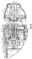
- FIG. 7is an enlarged cross-sectional view of a circled region in FIG. 2 .
- FIG. 8is a perspective view of the handpiece and treatment tip of FIG. 2 in which the treatment tip is shown separated from the handpiece.
- FIG. 9is an enlarged cross-sectional view similar to FIG. 7 in which the treatment tip is shown separated from the handpiece.
- a treatment apparatus 10includes a handpiece 12 , a treatment tip 14 coupled in a removable and releasable manner with the handpiece 12 , a console generally indicated by reference numeral 16 , and a system controller 18 .
- the system controller 18which is incorporated into the console 16 , controls the global operation of the different individual components of the treatment apparatus 10 .
- the treatment apparatus 10is adapted to selectively deliver electromagnetic energy in a high frequency band of the electromagnetic spectrum, such as the radiofrequency (RF) band to non-invasively heat a region of a patient's tissue to a targeted temperature range.
- RFradiofrequency
- the elevation in temperaturemay produce a desired treatment, such as removing or reducing wrinkles and otherwise tightening the skin to thereby improve the appearance of a patient 20 receiving the treatment.
- the treatment apparatus 10may be configured to deliver energy in the infrared band, microwave band, or another high frequency band of the electromagnetic spectrum, rather than energy in the RF band, to the patient's tissue.
- the treatment tip 14carries an energy delivery member in the representative form of a treatment electrode 22 .
- the treatment electrode 22is electrically coupled by a set of conductors 21 with a generator 38 configured to generate the electromagnetic energy used in the patient's treatment.
- the treatment electrode 22may have the form of a region 26 of an electrical conductor carried on an electrically-insulating substrate 28 composed of a dielectric material.
- the substrate 28may comprise a thin flexible base polymer film carrying the conductor region 26 and thin conductive (e.g., copper) traces or leads 24 on the substrate 28 that electrically couple the conductor region 26 with contact pads 25 .
- the base polymer filmmay be, for example, polyimide or another material with a relatively high electrical resistivity and a relatively high thermal conductivity.
- the conductive leads 24may contain copper or another material with a relatively high electrical conductivity.
- the conductor region 26 of treatment electrode 22may include voids or holes unfilled by the conductor to provide a perforated appearance or, alternatively, may be segmented into plural individual electrodes that can be individually powered by the generator 38 .
- the treatment electrode 22may comprise a flex circuit in which the substrate 28 consists of a base polymer film and the conductor region 26 consists of a patterned conductive (i.e., copper) foil laminated to the base polymer film.
- the treatment electrode 22may comprise a flex circuit in which the conductor region 26 consists of patterned conductive (i.e., copper) metallization layers directly deposited the base polymer film by, for example, a vacuum deposition technique, such as sputter deposition.
- the base polymer film constituting substrate 28may be replaced by another non-conductive dielectric material and the conductive metallization layers or foil constituting the conductor region 26 may contain copper.
- Flex circuitswhich are commonly used for flexible and high-density electronic interconnection applications, have a conventional construction understood by a person having ordinary skill in the art.
- the substrate 28includes a contact side 32 that is placed into contact with the skin surface of the patient 20 during treatment and a non-contact side 34 that is opposite to the contact side 32 .
- the conductor region 26 of the treatment electrode 22is physically carried on non-contact side 34 of the substrate 28 .
- the substrate 28is interposed between the conductor region 26 and the treated tissue such that, during the non-invasive tissue treatment, electromagnetic energy is transmitted from the conductor region 26 through the thickness of the substrate 28 by capacitively coupling with the tissue of the patient 20 .
- the contact pads 25face toward the handpiece 12 and are electrically coupled with electrical contacts (not shown), such as pogo pin contacts, inside the handpiece 12 .
- electrical contactsare electrically coupled with insulated and shielded conductors 21 that extend exteriorly of the handpiece 12 to a generator 38 at the console 16 .
- the generator 38which has the form of a high frequency power supply, is equipped with an electrical circuit (not shown) operative to generate high frequency electrical current, typically in the radio-frequency (RF) region of the electromagnetic spectrum.
- the operating frequency of generator 38may advantageously be in the range of several hundred kHz to about twenty (20) MHz to impart a therapeutic effect to treat target tissue beneath a patient's skin surface.
- the circuit in the generator 38converts a line voltage into drive signals having an energy content and duty cycle appropriate for the amount of power and the mode of operation that have been selected by the clinician, as understood by a person having ordinary skill in the art.
- the generator 38is a 400-watt, 6.78 MHz high frequency generator.
- a non-therapeutic passive or return electrode 40which is electrically coupled with the generator 38 , is physically attached to a site on the body surface of the patient 20 , such as the patient's lower back.
- high frequency currentflows from the treatment electrode 22 through the treated tissue and the intervening bulk of the patient 20 to the return electrode 40 and then through conductors inside a return cable 41 to define a closed circuit or current path 42 .
- the return electrode 40is non-therapeutic because negligible heating is produced at its attachment site to the patient 20 .
- High frequency electrical current flowing between the treatment electrode 22 and the patient 20is maximized at the skin surface and underlying tissue region adjacent to the treatment electrode 22 and, therefore, delivers a therapeutic effect to the tissue region near the treatment site.
- the treatment tip 14includes temperature sensors 44 , such as thermistors or thermocouples, that are located on the non-contact side 34 of the substrate 28 that is not in contact with the patient's skin surface. Typically, the temperature sensors 44 are arranged about the perimeter of the conductor region 26 of the treatment electrode 22 . Temperature sensors 44 are constructed to detect the temperature of the treatment electrode 22 and/or treatment tip 14 , which may be representative of the temperature of the treated tissue. Each of the temperature sensors 44 is electrically coupled by conductive leads 46 with one or more of the contact pads 25 , which are used to supply direct current (DC) voltages from the system controller 18 through the shielded conductors 21 to the temperature sensors 44 .
- DCdirect current
- the system controller 18regulates the power delivered from the generator 38 to the treatment electrode 22 and otherwise controls and supervises the operational parameters of the treatment apparatus 10 .
- the system controller 18may include user input devices to, for example, adjust the applied voltage level of generator 38 .
- the system controller 18includes a processor, which may be any suitable conventional microprocessor, microcontroller or digital signal processor, executing software to implement control algorithms for the operation of the generator 38 .
- System controller 18which may also include a nonvolatile memory (not shown) containing programmed instructions for the processor, may be optionally integrated into the generator 38 .
- System controller 18may also communicate, for example, with a nonvolatile memory carried by the handpiece 12 or by the treatment tip 14 .
- the system controller 18also includes circuitry for supplying the DC voltages and circuitry that relates changes in the DC voltages to the temperature detected by the temperature sensors 44 , as well as temperature sensors 90 and 88 .
- the handpiece 12is constructed from a body 48 and a cover 50 that is assembled with conventional fasteners with the body 48 .
- the assembled handpiece 12has a smoothly contoured shape suitable for manipulation by a clinician to maneuver the treatment tip 14 and treatment electrode 22 to a location proximate to the skin surface and, typically, in a contacting relationship with the skin surface.
- An activation button 36which is accessible to the clinician from the exterior of the handpiece 12 , is depressed for closing a switch that energizes the treatment electrode 22 and, thereby, delivers high frequency energy over a short delivery cycle to treat the target tissue. Releasing the activation button 36 opens the switch to discontinue the delivery of high frequency energy to the patient's skin surface and underlying tissue.
- the handpiece 12is manipulated to position the treatment tip 14 near a different site on the skin surface for another delivery cycle of high frequency energy delivery to the patient's tissue.
- the treatment tip 14includes a rigid outer shell 52 , a rear cover 54 that is coupled with an open rearward end of the outer shell 52 , and a manifold body 55 disposed inside an enclosure or housing inside the outer shell 52 .
- a portion of the substrate 28 overlying the conductor region 26 of the treatment electrode 22is exposed through a window 56 defined in a forward open end of the outer shell 52 .
- the substrate 28is wrapped or folded about the manifold body 55 .
- a hooked prong 58FIGS. 7 , 9 , which projects from the rear cover 54 , is captured by a lip on the handpiece 12 during installation of the treatment tip 14 .
- the manifold body 55which may be formed from an injection molded polymer resin, includes a front section 60 , a stem 62 projecting rearwardly from the front section 60 , and ribs 64 on the stem 62 used to position the manifold body 55 inside the outer shell 52 .
- the front section 60 of the manifold body 55includes a channel 66 that, in the assembly constituting treatment tip 14 , underlines the conductor region 26 of the treatment electrode 22 .
- the shape of the front section 60corresponds with the shape of the window 56 in the outer shell 52 .
- the substrate 28 of the treatment electrode 22is bonded with a rim 68 of the manifold body 55 to provide a fluid seal that confines heat transfer fluid 94 flowing in the channel 66 .
- the area inside the rim 68is approximately equal to the area of the conductor region 26 of treatment electrode 22 .
- Channel 66includes convolutions that are configured to optimize the residence time of the heat transfer fluid 94 in channel 66 , which may in turn optimize the heat transfer between the heat transfer fluid 94 and the treatment electrode 22 .
- An inlet bore or passage 70 and an outlet bore or passage 72extend through the stem 62 of the manifold body 55 .
- the inlet passage 70 and outlet passage 72are rearwardly accessible through an oval-shaped slot 74 defined in the rear cover 54 .
- the inlet passage 70intersects the channel 66 at an inlet 76 to the channel 66 and the outlet passage 72 intersects the channel 66 at an outlet 78 from the channel 66 .
- the channel 66is split into two channel sections 80 , 82 so that fluid flow in the channel 66 diverges away in two separate streams from the inlet 76 and converges together to flow into the outlet 78 .
- Fluid pressurecauses the heat transfer fluid 94 to flow from the inlet 76 through the two channel sections 80 , 82 to the outlet 78 and into the outlet passage 72 .
- fluid connectionsare established with the inlet passage 70 and the outlet passage 72 to establish the closed circulation loop and permit fluid flow to the channel 66 in the manifold body 55 when the treatment tip 14 is mated with the handpiece 12 .
- the inlet passage 70 to the manifold body 55is coupled with a supply line 86 in the form of an inlet conduit or tube.
- the outlet passage 72 from the manifold body 55is coupled with a return line 84 in the form of a fluid conduit or tube.
- the return line 84 and the supply lines 86extend out of the handpiece 12 and are routed to the console 16 . Structure facilitating the establishment of fluid-tight connections is described in detail hereinbelow.
- the treatment apparatus 10is equipped with a closed loop cooling system that includes the manifold body 55 located inside the treatment tip 14 .
- the closed loop cooling systemfurther includes a reservoir 96 holding a volume of a heat transfer fluid 94 and a pump 98 , which may be a diaphragm pump, that continuously pumps a stream of the heat transfer fluid 94 from an outlet of the reservoir 96 through the supply line 86 to the manifold body 55 in the treatment tip 14 .
- the manifold body 55is coupled in fluid communication with the reservoir 96 by the return line 84 .
- the return line 84conveys the heat transfer fluid 94 from the treatment tip 14 back to the reservoir 96 to complete the circulation loop.
- Heat generated in the treatment tip 14 by energy delivery from the treatment electrode 22 and heat transferred from the patient's skin and an underlying depth of heated tissueis conducted through the substrate 28 and treatment electrode 22 .
- the heatis absorbed by the circulating heat transfer fluid 94 in the channel 66 of the manifold body 55 , which lowers the temperature of the treatment electrode 22 and substrate 28 and, thereby, cools the patient's skin and the underlying depth of heated tissue.
- the contact coolingat the least, assists in regulating the depth over which the tissue is heated to a therapeutic temperature by the delivered electromagnetic energy.
- the heat transfer fluid 94 stored in the reservoir 96is chilled by a separate circulation loop 101 that pumps heat transfer fluid 94 from the reservoir 96 through separate supply and return lines to a coldplate 102 .
- a pump 100which may be a centrifugal pump, pumps the heat transfer fluid 94 under pressure from the reservoir 96 to the coldplate 102 .
- the coldplate 102may be a liquid-to-air heat exchanger that includes a liquid heat sink with a channel (not shown) for circulating the heat transfer fluid 94 , a thermoelectric module (not shown), and an air-cooled heat sink (not shown).
- a temperature controller 104 inside the console 16is electrically coupled with the coldplate 102 and is also electrically coupled with the system controller 18 .
- the system controller 18which is electrically coupled with a temperature sensor 88 used to measure the heat transfer fluid temperature in the reservoir 96 , supplies temperature control signals to the temperature controller 104 in response to the measured heat transfer fluid temperature. Under the feedback control, the temperature controller 104 reacts to the control temperature communicated from the temperature sensor 88 to control the operation of the coldplate 102 and, thereby, regulate the temperature of the heat transfer fluid 94 in the reservoir 96 .
- the handpiece 12includes a pair of rigid tubes 110 , 112 with respective tips 114 , 116 that project outwardly from a flow part 118 .
- the flow part 118conceals the portions of the rigid tubes 110 , 112 located inside the handpiece 12 .
- the rigid tubes 110 , 112extend through respective openings penetrating through the flow part 118 and have lumens 111 , 113 that are respectively coupled inside the handpiece 12 with a pair of flexible conduits or lines 120 , 122 .
- a flow control valve in the representative form of a pinch valveis located inside the handpiece 12 .
- the pinch valve 124includes a pin 126 , a movable member in the form of a ram or plunger 128 that is mechanically coupled with the pin 126 to form an assembly, a stationary member in the form of an anvil body 130 on the flow part 118 , and an actuator in the representative form of a coil spring 132 that is configured to apply a biasing force to the plunger 128 .
- a forward end 125 of the pin 126is centrally located between the tips 114 , 116 of the rigid tubes 110 , 112 and, inside the handpiece 12 , the remainder of the pin 126 is centrally located between the rigid tubes 110 , 112 and the flexible lines 120 , 122 .
- the anvil body 130includes a spaced-apart pair of contoured contact or pinch surfaces 134 , 136 .
- One of the flexible lines 120is located between a contact or pinch surface 138 of plunger 128 and pinch surface 134 on the anvil body 130 .
- the other flexible line 122is located between a contact or pinch surface 140 of plunger 128 and pinch surface 136 on the anvil body 130 .
- the pinch valve 124has a first closed position ( FIGS. 8 , 9 ) in which the flexible lines 120 , 122 are respectively compressed between the pinch surfaces 134 , 136 on anvil body 130 and the pinch surfaces 138 , 140 on plunger 128 .
- the material forming the flexible lines 120 , 122is sufficiently compliant to the compressive force or pressure from the pinching action so that the respective sidewalls collapse inwardly to totally or partially occlude a lumen 142 of flexible line 120 and a lumen 144 of flexible line 122 .
- heat transfer fluid 94is substantially or completely occluded by the pinch valve 124 from flowing through the flexible lines 120 , 122 to an extent sufficient to reduce or eliminate fluid leakage from the outlets of the rigid tubes 110 , 112 .
- the closed positionoccurs when the treatment tip 14 is removed from the handpiece 12 .
- the rigid tubes 110 , 112which are relatively short in comparison with the flexible lines 120 , 122 , may be formed from a stainless steel.
- the flexible lines 120 , 122are formed from a polymer or an elastomeric material, like a silicone rubber, that is significantly more flexible (has a greater ability to bend) than the material forming the rigid tubes 110 , 112 .
- the flexible lines 120 , 122are formed from a material having a significantly lower shear modulus or modulus of rigidity than a material forming the rigid tubes 110 , 112 .
- Flexible line 120has a tubular sidewall 121 composed of a material with sufficient flexibility to at least partially occlude the enclosed lumen 142 by reducing the cross-sectional area for fluid flow when a compressive force is applied between pinch surface 138 of plunger 128 and pinch surface 134 on the anvil body 130 of the pinch valve 124 .
- the occlusionwhich controls the flow of fluid through the lumen 142 , causes deformation that at least partially collapses the lumen 142 .
- flexible line 122has a tubular sidewall 123 composed of a material with sufficient flexibility to at least partially occlude the enclosed lumen 144 by reducing the cross-sectional area for fluid flow when a compressive force is applied between pinch surface 140 of plunger 128 and pinch surface 136 on the anvil body 130 of the pinch valve 124 .
- the occlusionwhich controls the flow of fluid through the lumen 144 , causes deformation that at least partially collapses the lumen 144 .
- the deformation of the tubular sidewalls 121 , 123is primarily elastic in that the tubular sidewalls 121 , 123 return to substantially their original shape and cross-sectional area when the compressive force is removed.
- respective columns of residual heat transfer fluid 94may remain inside the rigid tubes 110 , 112 , as well as inside the portion of the flexible lines 120 , 122 between the pinch surfaces 134 , 136 , 138 , 140 and the rigid tubes 110 , 112 .
- the columnsmay remain static and resident inside the handpiece 12 until another treatment tip 14 is installed, which implies that the effective flow rate is zero milliliters per minute.
- the pinch valve 124has an open position ( FIGS. 4 , 7 ) in which the pinch surfaces 138 , 140 on plunger 128 are separated from the pinch surfaces 134 , 136 on anvil body 130 so that the flexible lines 120 , 122 are not compressed therebetween.
- heat transfer fluid 94is permitted to flow at a given flow rate through the lumen 142 of flexible line 120 to the manifold body 55 inside the treatment tip 14 and to flow through the lumen 144 of flexible line 122 out of the manifold body 55 .
- the second positionis created when the treatment tip 14 is installed on the nose of the handpiece 12 .
- the inlet passage 70 in the stem 62 of the manifold body 55has a tubular section 152 truncated to terminate at an open end.
- the outlet passage 72 in the stem 62 of the manifold body 55has a tubular section 154 terminating at another end.
- the tubular sections 152 , 154are raised above the surrounding portions of the manifold body 55 and project toward the handpiece 12 when the treatment tip 14 is installed to establish a fluid interface with the handpiece 12 .
- the tubular sections 152 , 154intersect to define a central activation arm 146 .
- a contact block 145is located on an opposite side of a septum 150 from the activation arm 146 .
- the contact block 145 and activation arm 146participate in providing the open position when the treatment tip 14 is installed in the nose of the handpiece 12 , as depicted in FIGS. 4 and 7 .
- the activation arm 146 and contact block 145which are self-aligned, are also aligned with the pin 126 of the pinch valve 124 .
- the contact block 145contacts a portion of the pin 126 .
- the activation arm 146prevents the septum 150 from deflecting as a reinforcement force is applied by the pin 126 to the contact block 145 .
- the pin 126 and the plunger 128are pushed by the activation arm 146 and contact block 145 in a direction away from the treatment tip 14 and against the biasing force applied by the coil spring 132 to the plunger 128 that resists motion toward the open position.
- the coil spring 132compresses so as to store biasing energy for use in applying a force urging the pinch valve 124 to re-establish the first closed position ( FIGS. 8 , 9 ).
- the coil spring 132must apply a spring force to the plunger 128 that is sufficient to compress the flexible lines 120 , 122 and place the pinch valve 124 in its closed position. However, the coil spring 132 must readily yield to permit installation of the treatment tip 14 and establish the open position of pinch valve 124 . Hence, the properties of the coil spring 132 should be selected to apply an appropriate spring force to the plunger 128 .
- the flexible lines 120 , 122isolate the heat transfer fluid 94 inside the closed-loop cooling from the components of the pinch valve 124 , which prevents contact between the components and the heat transfer fluid 94 .
- the tubing constituting flexible lines 120 , 122is always imposed between the heat transfer fluid 94 and the components of the pinch valve 124 , which may be beneficial, for example, if contact with the heat transfer fluid 94 is capable of corroding the components of the pinch valve 124 .
- This benefitmeans that the materials for the components of the pinch valve 124 are not constrained to be corrosion resistant to the heat transfer fluid 94 as these components are not wetted by the heat transfer fluid 94 . Fluid transfer can be effectively controlled by the pinch valve 124 without concerns raised by fluid wetting of the valve components.
- the septum 150which is best shown in FIGS. 4 and 9 , covers the open end 151 of the inlet passage 70 and the open end 153 of the outlet passage 72 .
- the tips 114 , 116 of the rigid tubes 110 , 112apply a force that is substantially perpendicular to the plane of the septum 150 .
- the applied forcepierces the septum 150 to define openings 115 , 117 that place the lumens 111 , 113 of the rigid tubes 110 , 112 in fluid communication with the inlet and outlet passages 70 , 72 , respectively.
- These temporary fluid connectionswhich are formed when the treatment tip 14 is attached to the handpiece 12 , complete the closed circulation loop.
- the septum 150heals to close or substantially close the openings 115 , 117 so that residual heat transfer fluid 94 remaining in the detached treatment tip 14 is blocked from escape.
- the tip 114 of the rigid tube 110protrudes through the opening 115 in the septum 150 and projects into an enlarged region at the entrance to the inlet passage 72 .
- the tip 116 of the rigid tube 112protrudes through the opening 117 in the septum 150 and projects into an enlarged region at the entrance to the outlet passage 70 .
- the material of septum 150 about the openings 115 , 117grips the exterior of the tips 114 , 116 so that fluid-tight connections are established.
- the septum 150is a thin membrane composed of an elastomeric material characterized by properties that permit the tips 114 , 116 of the rigid tubes 110 , 112 to pierce the septum 150 and, upon withdrawal of the tips 114 , 116 , permit the membrane to heal or close the openings 115 , 117 so that residual heat transfer fluid 94 is retained in the treatment tip 14 .
- the elastomeric materialwhen pierced at spaced apart locations by the tips 114 , 116 of the rigid tubes 110 , 112 , near the edges of openings 115 , 117 compresses slightly and grips about the outer diameter of each of the rigid tubes 110 , 112 with a radial reaction force.
- Starter openings 156 , 158are provided in the septum 150 at the approximate locations at which the septum 150 is pierced by the tips 114 , 116 of the rigid tubes 110 , 112 .
- the starter openings 156 , 158function to permit the tips 114 , 116 to initiate penetration through the septum 150 and the formation of openings 115 , 117 with a reduced likelihood of either tearing or ripping the septum 150 .
- the septum 150is composed of an elastomeric membrane that is either adhesively bonded with the rear cover 54 or, when the rear cover 54 is integrally formed, with the rear cover 54 by an overmolding process.
- the septum 150may be formed from a material having a durometer of about 30 Shore A, as measured by the ASTM D2240 type A scale, and a thickness in a range of about 25 mils to about 35 mils. These combinations of durometer (i.e., the material's resistance to permanent indentation) and thicknesses is believed adequate to impart tear and rip resistance when the tips 114 , 116 pierce the septum 150 .
- Other representative materials for septum 150include, but are not limited to, thermoplastic elastomers (TPEs), such as the DYNAFLEX® family of TPE compounds commercially available from GLS Corporation (McHenry, Ill.).
Landscapes
- Health & Medical Sciences (AREA)
- Surgery (AREA)
- Engineering & Computer Science (AREA)
- Life Sciences & Earth Sciences (AREA)
- Biomedical Technology (AREA)
- Otolaryngology (AREA)
- Nuclear Medicine, Radiotherapy & Molecular Imaging (AREA)
- Plasma & Fusion (AREA)
- Physics & Mathematics (AREA)
- Heart & Thoracic Surgery (AREA)
- Medical Informatics (AREA)
- Molecular Biology (AREA)
- Animal Behavior & Ethology (AREA)
- General Health & Medical Sciences (AREA)
- Public Health (AREA)
- Veterinary Medicine (AREA)
- Surgical Instruments (AREA)
Abstract
Description
Claims (15)
Priority Applications (1)
| Application Number | Priority Date | Filing Date | Title |
|---|---|---|---|
| US12/142,020US8285392B2 (en) | 2008-06-19 | 2008-06-19 | Leakage-resistant tissue treatment apparatus and methods of using such tissue treatment apparatus |
Applications Claiming Priority (1)
| Application Number | Priority Date | Filing Date | Title |
|---|---|---|---|
| US12/142,020US8285392B2 (en) | 2008-06-19 | 2008-06-19 | Leakage-resistant tissue treatment apparatus and methods of using such tissue treatment apparatus |
Publications (2)
| Publication Number | Publication Date |
|---|---|
| US20090318851A1 US20090318851A1 (en) | 2009-12-24 |
| US8285392B2true US8285392B2 (en) | 2012-10-09 |
Family
ID=41431957
Family Applications (1)
| Application Number | Title | Priority Date | Filing Date |
|---|---|---|---|
| US12/142,020Expired - Fee RelatedUS8285392B2 (en) | 2008-06-19 | 2008-06-19 | Leakage-resistant tissue treatment apparatus and methods of using such tissue treatment apparatus |
Country Status (1)
| Country | Link |
|---|---|
| US (1) | US8285392B2 (en) |
Cited By (2)
| Publication number | Priority date | Publication date | Assignee | Title |
|---|---|---|---|---|
| US10376307B2 (en) | 2006-02-07 | 2019-08-13 | Viveve, Inc. | Vaginal remodeling device and methods |
| US11511110B2 (en) | 2018-06-27 | 2022-11-29 | Viveve, Inc. | Methods for treating urinary stress incontinence |
Families Citing this family (12)
| Publication number | Priority date | Publication date | Assignee | Title |
|---|---|---|---|---|
| US9132031B2 (en)* | 2006-09-26 | 2015-09-15 | Zeltiq Aesthetics, Inc. | Cooling device having a plurality of controllable cooling elements to provide a predetermined cooling profile |
| US8272380B2 (en) | 2008-03-31 | 2012-09-25 | Nellcor Puritan Bennett, Llc | Leak-compensated pressure triggering in medical ventilators |
| US10207069B2 (en) | 2008-03-31 | 2019-02-19 | Covidien Lp | System and method for determining ventilator leakage during stable periods within a breath |
| US8267085B2 (en) | 2009-03-20 | 2012-09-18 | Nellcor Puritan Bennett Llc | Leak-compensated proportional assist ventilation |
| US8746248B2 (en) | 2008-03-31 | 2014-06-10 | Covidien Lp | Determination of patient circuit disconnect in leak-compensated ventilatory support |
| US8424521B2 (en) | 2009-02-27 | 2013-04-23 | Covidien Lp | Leak-compensated respiratory mechanics estimation in medical ventilators |
| US8418691B2 (en) | 2009-03-20 | 2013-04-16 | Covidien Lp | Leak-compensated pressure regulated volume control ventilation |
| US9498589B2 (en) | 2011-12-31 | 2016-11-22 | Covidien Lp | Methods and systems for adaptive base flow and leak compensation |
| US9675771B2 (en) | 2013-10-18 | 2017-06-13 | Covidien Lp | Methods and systems for leak estimation |
| US20150216719A1 (en) | 2014-01-31 | 2015-08-06 | Zeltiq Aesthetics, Inc | Treatment systems and methods for treating cellulite and for providing other treatments |
| WO2020028472A1 (en) | 2018-07-31 | 2020-02-06 | Zeltiq Aesthetics, Inc. | Methods, devices, and systems for improving skin characteristics |
| WO2021026470A1 (en)* | 2019-08-07 | 2021-02-11 | Biocompatibles Uk Limited | Cooling system for surgical device |
Citations (55)
| Publication number | Priority date | Publication date | Assignee | Title |
|---|---|---|---|---|
| US3948269A (en) | 1973-08-31 | 1976-04-06 | Dragerwerk Aktiengesellschaft | Cryomedical device |
| US5195958A (en)* | 1990-05-25 | 1993-03-23 | Phillips Edward H | Tool for laparoscopic surgery |
| US5281213A (en) | 1992-04-16 | 1994-01-25 | Implemed, Inc. | Catheter for ice mapping and ablation |
| US5348554A (en) | 1992-12-01 | 1994-09-20 | Cardiac Pathways Corporation | Catheter for RF ablation with cooled electrode |
| US5735846A (en) | 1994-06-27 | 1998-04-07 | Ep Technologies, Inc. | Systems and methods for ablating body tissue using predicted maximum tissue temperature |
| US5755753A (en) | 1995-05-05 | 1998-05-26 | Thermage, Inc. | Method for controlled contraction of collagen tissue |
| US5871524A (en) | 1995-05-05 | 1999-02-16 | Thermage, Inc. | Apparatus for controlled contraction of collagen tissue |
| WO1999016502A1 (en) | 1997-09-30 | 1999-04-08 | Thermage, Inc. | Method and apparatus for tissue remodeling |
| US5948011A (en) | 1995-05-05 | 1999-09-07 | Thermage, Inc. | Method for controlled contraction of collagen tissue via non-continuous energy delivery |
| US6035238A (en) | 1997-08-13 | 2000-03-07 | Surx, Inc. | Noninvasive devices, methods, and systems for shrinking of tissues |
| US6059780A (en) | 1995-08-15 | 2000-05-09 | Rita Medical Systems, Inc. | Multiple antenna ablation apparatus and method with cooling element |
| US6081749A (en) | 1997-08-13 | 2000-06-27 | Surx, Inc. | Noninvasive devices, methods, and systems for shrinking of tissues |
| WO2000053113A1 (en) | 1999-03-09 | 2000-09-14 | Thermage, Inc. | Apparatus and method for treatment of tissue |
| US6139569A (en) | 1998-07-31 | 2000-10-31 | Surx, Inc. | Interspersed heating/cooling to shrink tissues for incontinence |
| WO2001000269A1 (en) | 1999-06-30 | 2001-01-04 | Thermage, Inc. | Fluid delivery apparatus |
| US6216704B1 (en) | 1997-08-13 | 2001-04-17 | Surx, Inc. | Noninvasive devices, methods, and systems for shrinking of tissues |
| US6236891B1 (en) | 1998-07-31 | 2001-05-22 | Surx, Inc. | Limited heat transfer devices and methods to shrink tissues |
| US6283987B1 (en) | 1998-01-14 | 2001-09-04 | Surx, Inc. | Ribbed electrodes and methods for their use |
| US6322584B2 (en) | 1998-07-31 | 2001-11-27 | Surx, Inc. | Temperature sensing devices and methods to shrink tissues |
| US6430446B1 (en) | 1995-05-05 | 2002-08-06 | Thermage, Inc. | Apparatus for tissue remodeling |
| US6480746B1 (en) | 1997-08-13 | 2002-11-12 | Surx, Inc. | Noninvasive devices, methods, and systems for shrinking of tissues |
| US6524308B1 (en) | 1997-09-04 | 2003-02-25 | Celon Ag Medical Instruments | Electrode arrangement for electrothermal treatment of human or animal bodies |
| US6572639B1 (en) | 1998-07-31 | 2003-06-03 | Surx, Inc. | Interspersed heating/cooling to shrink tissues for incontinence |
| WO2003053266A2 (en) | 1999-06-30 | 2003-07-03 | Thermage, Inc. | Liquid cooled rf handpiece |
| WO2003065915A1 (en) | 2002-02-06 | 2003-08-14 | Thermage, Inc. | Handpiece for rf treatment of tissue |
| WO2003065916A1 (en) | 2002-02-06 | 2003-08-14 | Thermage, Inc. | Handpiece for rf treatment of tissue |
| US20030178032A1 (en) | 1997-08-13 | 2003-09-25 | Surx, Inc. | Noninvasive devices, methods, and systems for shrinking of tissues |
| WO2003086217A1 (en) | 2002-04-05 | 2003-10-23 | Thermage, Inc. | Method for treatment of tissue |
| US20030216719A1 (en) | 2001-12-12 | 2003-11-20 | Len Debenedictis | Method and apparatus for treating skin using patterns of optical energy |
| US6702808B1 (en) | 2000-09-28 | 2004-03-09 | Syneron Medical Ltd. | Device and method for treating skin |
| US6719449B1 (en) | 1998-10-28 | 2004-04-13 | Covaris, Inc. | Apparatus and method for controlling sonic treatment |
| US20040082940A1 (en) | 2002-10-22 | 2004-04-29 | Michael Black | Dermatological apparatus and method |
| WO2004088700A2 (en) | 2003-03-25 | 2004-10-14 | Thermage, Inc. | Rf device with thermo-electric cooler |
| WO2004086943A2 (en) | 2003-03-25 | 2004-10-14 | Thermage, Inc. | Method and kit for treatment of tissue |
| WO2004087253A2 (en) | 2003-03-25 | 2004-10-14 | Thermage, Inc. | Rf electrode assembly for handpiece |
| WO2004090939A2 (en) | 2003-03-31 | 2004-10-21 | Thermage, Inc. | Handpiece with rf electrode and non-volatile memory |
| WO2004089185A2 (en) | 2003-03-31 | 2004-10-21 | Thermage, Inc. | Methods for creating tissue effect utilizing electromagnetic energy and a reverse thermal gradient |
| WO2004089459A2 (en) | 2003-03-31 | 2004-10-21 | Thermage, Inc. | Treatment apparatus with electromagnetic energy delivery device and non-volatile memory |
| WO2004089186A2 (en) | 2003-03-31 | 2004-10-21 | Thermage, Inc. | Handpiece with rf electrode and non-volatile memory |
| WO2004089460A2 (en) | 2003-03-31 | 2004-10-21 | Thermage, Inc. | Methods for creating tissue effect |
| WO2004105861A2 (en) | 2003-05-27 | 2004-12-09 | Thermage, Inc. | Method for treating skin and underlying tissue |
| US20050049582A1 (en) | 2001-12-12 | 2005-03-03 | Debenedictis Leonard C. | Method and apparatus for fractional photo therapy of skin |
| US20050171582A1 (en) | 2004-01-30 | 2005-08-04 | Solarant Medical, Inc. | Electrically heated/phase change probe temperature control |
| US20060009750A1 (en) | 2001-03-02 | 2006-01-12 | Palomar Medical Technologies, Inc. | Apparatus and method for treatment using a patterned mask |
| US6997923B2 (en) | 2000-12-28 | 2006-02-14 | Palomar Medical Technologies, Inc. | Method and apparatus for EMR treatment |
| US20060149343A1 (en) | 1996-12-02 | 2006-07-06 | Palomar Medical Technologies, Inc. | Cooling system for a photocosmetic device |
| US7090670B2 (en) | 2003-12-31 | 2006-08-15 | Reliant Technologies, Inc. | Multi-spot laser surgical apparatus and method |
| US20060206179A1 (en) | 2002-04-12 | 2006-09-14 | Reliant Technologies, Inc. | Temperature Controlled Heating Device and Method to Heat a Selected Area of a Biological Body |
| US20060206103A1 (en) | 2001-03-02 | 2006-09-14 | Palomar Medical Technologies, Inc. | Dermatological treatment device |
| US7164942B2 (en) | 1998-11-09 | 2007-01-16 | Transpharma Medical Ltd. | Handheld apparatus and method for transdermal drug delivery and analyte extraction |
| USD544955S1 (en) | 2003-02-05 | 2007-06-19 | Thermage, Inc. | Medical device tip |
| US7257450B2 (en) | 2003-02-13 | 2007-08-14 | Coaptus Medical Corporation | Systems and methods for securing cardiovascular tissue |
| US7473252B2 (en) | 2004-10-07 | 2009-01-06 | Coaptus Medical Corporation | Systems and methods for shrinking and/or securing cardiovascular tissue |
| US7494488B2 (en) | 1998-05-28 | 2009-02-24 | Pearl Technology Holdings, Llc | Facial tissue strengthening and tightening device and methods |
| US8121704B2 (en)* | 2008-06-19 | 2012-02-21 | Thermage, Inc. | Leakage-resistant tissue treatment apparatus and methods of using same |
- 2008
- 2008-06-19USUS12/142,020patent/US8285392B2/ennot_activeExpired - Fee Related
Patent Citations (88)
| Publication number | Priority date | Publication date | Assignee | Title |
|---|---|---|---|---|
| US3948269A (en) | 1973-08-31 | 1976-04-06 | Dragerwerk Aktiengesellschaft | Cryomedical device |
| US5195958A (en)* | 1990-05-25 | 1993-03-23 | Phillips Edward H | Tool for laparoscopic surgery |
| US5281213A (en) | 1992-04-16 | 1994-01-25 | Implemed, Inc. | Catheter for ice mapping and ablation |
| US5348554A (en) | 1992-12-01 | 1994-09-20 | Cardiac Pathways Corporation | Catheter for RF ablation with cooled electrode |
| US5423811A (en) | 1992-12-01 | 1995-06-13 | Cardiac Pathways Corporation | Method for RF ablation using cooled electrode |
| US5697927A (en) | 1992-12-01 | 1997-12-16 | Cardiac Pathways Corporation | Catheter for RF ablation with cooled electrode and apparatus for use therewith |
| US5735846A (en) | 1994-06-27 | 1998-04-07 | Ep Technologies, Inc. | Systems and methods for ablating body tissue using predicted maximum tissue temperature |
| US6438424B1 (en) | 1995-05-05 | 2002-08-20 | Thermage, Inc. | Apparatus for tissue remodeling |
| US6425912B1 (en) | 1995-05-05 | 2002-07-30 | Thermage, Inc. | Method and apparatus for modifying skin surface and soft tissue structure |
| US6461378B1 (en) | 1995-05-05 | 2002-10-08 | Thermage, Inc. | Apparatus for smoothing contour irregularities of skin surface |
| US6430446B1 (en) | 1995-05-05 | 2002-08-06 | Thermage, Inc. | Apparatus for tissue remodeling |
| US5948011A (en) | 1995-05-05 | 1999-09-07 | Thermage, Inc. | Method for controlled contraction of collagen tissue via non-continuous energy delivery |
| US6377854B1 (en) | 1995-05-05 | 2002-04-23 | Thermage, Inc. | Method for controlled contraction of collagen in fibrous septae in subcutaneous fat layers |
| US6377855B1 (en) | 1995-05-05 | 2002-04-23 | Thermage, Inc. | Method and apparatus for controlled contraction of collagen tissue |
| US6453202B1 (en) | 1995-05-05 | 2002-09-17 | Thermage, Inc. | Method and apparatus for controlled contraction of collagen tissue |
| US5871524A (en) | 1995-05-05 | 1999-02-16 | Thermage, Inc. | Apparatus for controlled contraction of collagen tissue |
| US5755753A (en) | 1995-05-05 | 1998-05-26 | Thermage, Inc. | Method for controlled contraction of collagen tissue |
| US5919219A (en) | 1995-05-05 | 1999-07-06 | Thermage, Inc. | Method for controlled contraction of collagen tissue using RF energy |
| US6405090B1 (en) | 1995-05-05 | 2002-06-11 | Thermage, Inc. | Method and apparatus for tightening skin by controlled contraction of collagen tissue |
| US6387380B1 (en) | 1995-05-05 | 2002-05-14 | Thermage, Inc. | Apparatus for controlled contraction of collagen tissue |
| US6241753B1 (en) | 1995-05-05 | 2001-06-05 | Thermage, Inc. | Method for scar collagen formation and contraction |
| US6381497B1 (en) | 1995-05-05 | 2002-04-30 | Thermage, Inc. | Method for smoothing contour irregularity of skin surface by controlled contraction of collagen tissue |
| US6311090B1 (en) | 1995-05-05 | 2001-10-30 | Thermage, Inc. | Method and apparatus for controlled contraction of collagen tissue |
| US6470216B1 (en) | 1995-05-05 | 2002-10-22 | Thermage, Inc. | Method for smoothing contour irregularities of skin surface |
| US6381498B1 (en) | 1995-05-05 | 2002-04-30 | Thermage, Inc. | Method and apparatus for controlled contraction of collagen tissue |
| US6059780A (en) | 1995-08-15 | 2000-05-09 | Rita Medical Systems, Inc. | Multiple antenna ablation apparatus and method with cooling element |
| US7006874B2 (en) | 1996-01-05 | 2006-02-28 | Thermage, Inc. | Treatment apparatus with electromagnetic energy delivery device and non-volatile memory |
| US6350276B1 (en) | 1996-01-05 | 2002-02-26 | Thermage, Inc. | Tissue remodeling apparatus containing cooling fluid |
| US7452358B2 (en) | 1996-01-05 | 2008-11-18 | Thermage, Inc. | RF electrode assembly for handpiece |
| US7267675B2 (en) | 1996-01-05 | 2007-09-11 | Thermage, Inc. | RF device with thermo-electric cooler |
| US7229436B2 (en) | 1996-01-05 | 2007-06-12 | Thermage, Inc. | Method and kit for treatment of tissue |
| US7473251B2 (en) | 1996-01-05 | 2009-01-06 | Thermage, Inc. | Methods for creating tissue effect utilizing electromagnetic energy and a reverse thermal gradient |
| US7481809B2 (en) | 1996-01-05 | 2009-01-27 | Thermage, Inc. | Handpiece with RF electrode and non-volatile memory |
| US7189230B2 (en) | 1996-01-05 | 2007-03-13 | Thermage, Inc. | Method for treating skin and underlying tissue |
| US7115123B2 (en) | 1996-01-05 | 2006-10-03 | Thermage, Inc. | Handpiece with electrode and non-volatile memory |
| US20060149343A1 (en) | 1996-12-02 | 2006-07-06 | Palomar Medical Technologies, Inc. | Cooling system for a photocosmetic device |
| US6035238A (en) | 1997-08-13 | 2000-03-07 | Surx, Inc. | Noninvasive devices, methods, and systems for shrinking of tissues |
| US6216704B1 (en) | 1997-08-13 | 2001-04-17 | Surx, Inc. | Noninvasive devices, methods, and systems for shrinking of tissues |
| US6480746B1 (en) | 1997-08-13 | 2002-11-12 | Surx, Inc. | Noninvasive devices, methods, and systems for shrinking of tissues |
| US6976492B2 (en) | 1997-08-13 | 2005-12-20 | Solarant Medical, Inc. | Noninvasive devices, methods, and systems for shrinking of tissues |
| US6533780B1 (en) | 1997-08-13 | 2003-03-18 | Surx, Inc. | Ribbed electrodes and methods for their use |
| US6558381B2 (en) | 1997-08-13 | 2003-05-06 | Surx, Inc. | Noninvasive devices, methods, and systems for shrinking of tissues |
| US6081749A (en) | 1997-08-13 | 2000-06-27 | Surx, Inc. | Noninvasive devices, methods, and systems for shrinking of tissues |
| US20030178032A1 (en) | 1997-08-13 | 2003-09-25 | Surx, Inc. | Noninvasive devices, methods, and systems for shrinking of tissues |
| US6524308B1 (en) | 1997-09-04 | 2003-02-25 | Celon Ag Medical Instruments | Electrode arrangement for electrothermal treatment of human or animal bodies |
| WO1999016502A1 (en) | 1997-09-30 | 1999-04-08 | Thermage, Inc. | Method and apparatus for tissue remodeling |
| US6283987B1 (en) | 1998-01-14 | 2001-09-04 | Surx, Inc. | Ribbed electrodes and methods for their use |
| US7494488B2 (en) | 1998-05-28 | 2009-02-24 | Pearl Technology Holdings, Llc | Facial tissue strengthening and tightening device and methods |
| US6236891B1 (en) | 1998-07-31 | 2001-05-22 | Surx, Inc. | Limited heat transfer devices and methods to shrink tissues |
| US6322584B2 (en) | 1998-07-31 | 2001-11-27 | Surx, Inc. | Temperature sensing devices and methods to shrink tissues |
| US6139569A (en) | 1998-07-31 | 2000-10-31 | Surx, Inc. | Interspersed heating/cooling to shrink tissues for incontinence |
| US6572639B1 (en) | 1998-07-31 | 2003-06-03 | Surx, Inc. | Interspersed heating/cooling to shrink tissues for incontinence |
| US6719449B1 (en) | 1998-10-28 | 2004-04-13 | Covaris, Inc. | Apparatus and method for controlling sonic treatment |
| US7164942B2 (en) | 1998-11-09 | 2007-01-16 | Transpharma Medical Ltd. | Handheld apparatus and method for transdermal drug delivery and analyte extraction |
| US7022121B2 (en) | 1999-03-09 | 2006-04-04 | Thermage, Inc. | Handpiece for treatment of tissue |
| WO2000053113A1 (en) | 1999-03-09 | 2000-09-14 | Thermage, Inc. | Apparatus and method for treatment of tissue |
| US6413255B1 (en)* | 1999-03-09 | 2002-07-02 | Thermage, Inc. | Apparatus and method for treatment of tissue |
| US7141049B2 (en) | 1999-03-09 | 2006-11-28 | Thermage, Inc. | Handpiece for treatment of tissue |
| WO2001000269A1 (en) | 1999-06-30 | 2001-01-04 | Thermage, Inc. | Fluid delivery apparatus |
| WO2003053266A2 (en) | 1999-06-30 | 2003-07-03 | Thermage, Inc. | Liquid cooled rf handpiece |
| US6702808B1 (en) | 2000-09-28 | 2004-03-09 | Syneron Medical Ltd. | Device and method for treating skin |
| US6997923B2 (en) | 2000-12-28 | 2006-02-14 | Palomar Medical Technologies, Inc. | Method and apparatus for EMR treatment |
| US20060122668A1 (en) | 2000-12-28 | 2006-06-08 | Palomar Medical Technologies, Inc. | Method and apparatus for EMR treatment |
| US20060206103A1 (en) | 2001-03-02 | 2006-09-14 | Palomar Medical Technologies, Inc. | Dermatological treatment device |
| US20060009750A1 (en) | 2001-03-02 | 2006-01-12 | Palomar Medical Technologies, Inc. | Apparatus and method for treatment using a patterned mask |
| US20030216719A1 (en) | 2001-12-12 | 2003-11-20 | Len Debenedictis | Method and apparatus for treating skin using patterns of optical energy |
| US20050049582A1 (en) | 2001-12-12 | 2005-03-03 | Debenedictis Leonard C. | Method and apparatus for fractional photo therapy of skin |
| WO2003065916A1 (en) | 2002-02-06 | 2003-08-14 | Thermage, Inc. | Handpiece for rf treatment of tissue |
| WO2003065915A1 (en) | 2002-02-06 | 2003-08-14 | Thermage, Inc. | Handpiece for rf treatment of tissue |
| WO2003086217A1 (en) | 2002-04-05 | 2003-10-23 | Thermage, Inc. | Method for treatment of tissue |
| US20060206179A1 (en) | 2002-04-12 | 2006-09-14 | Reliant Technologies, Inc. | Temperature Controlled Heating Device and Method to Heat a Selected Area of a Biological Body |
| US20040082940A1 (en) | 2002-10-22 | 2004-04-29 | Michael Black | Dermatological apparatus and method |
| USD544955S1 (en) | 2003-02-05 | 2007-06-19 | Thermage, Inc. | Medical device tip |
| US7257450B2 (en) | 2003-02-13 | 2007-08-14 | Coaptus Medical Corporation | Systems and methods for securing cardiovascular tissue |
| WO2004087253A2 (en) | 2003-03-25 | 2004-10-14 | Thermage, Inc. | Rf electrode assembly for handpiece |
| WO2004088700A2 (en) | 2003-03-25 | 2004-10-14 | Thermage, Inc. | Rf device with thermo-electric cooler |
| WO2004086943A2 (en) | 2003-03-25 | 2004-10-14 | Thermage, Inc. | Method and kit for treatment of tissue |
| WO2004089186A2 (en) | 2003-03-31 | 2004-10-21 | Thermage, Inc. | Handpiece with rf electrode and non-volatile memory |
| WO2004090939A2 (en) | 2003-03-31 | 2004-10-21 | Thermage, Inc. | Handpiece with rf electrode and non-volatile memory |
| WO2004089460A2 (en) | 2003-03-31 | 2004-10-21 | Thermage, Inc. | Methods for creating tissue effect |
| WO2004089459A2 (en) | 2003-03-31 | 2004-10-21 | Thermage, Inc. | Treatment apparatus with electromagnetic energy delivery device and non-volatile memory |
| WO2004089185A2 (en) | 2003-03-31 | 2004-10-21 | Thermage, Inc. | Methods for creating tissue effect utilizing electromagnetic energy and a reverse thermal gradient |
| WO2004105861A2 (en) | 2003-05-27 | 2004-12-09 | Thermage, Inc. | Method for treating skin and underlying tissue |
| US7090670B2 (en) | 2003-12-31 | 2006-08-15 | Reliant Technologies, Inc. | Multi-spot laser surgical apparatus and method |
| US20050171582A1 (en) | 2004-01-30 | 2005-08-04 | Solarant Medical, Inc. | Electrically heated/phase change probe temperature control |
| US7476242B2 (en) | 2004-01-30 | 2009-01-13 | Ams Research Corporation | Electrically heated/phase change probe temperature control |
| US7473252B2 (en) | 2004-10-07 | 2009-01-06 | Coaptus Medical Corporation | Systems and methods for shrinking and/or securing cardiovascular tissue |
| US8121704B2 (en)* | 2008-06-19 | 2012-02-21 | Thermage, Inc. | Leakage-resistant tissue treatment apparatus and methods of using same |
Non-Patent Citations (4)
| Title |
|---|
| Schenck, "Apparatus and Methods for Cooling a Treatment Apparatus Configured to Non-Invasively Deliver Electromagnetic Energy to a Patient's Tissue", U.S. Appl. No. 11/952,649, filed Dec. 7, 2007. |
| Schenck, "Leakage-Resistant Tissue Treatment Apparatus and Methods of Using Same", U.S. Appl. No. 12/142,104, filed Jun. 19, 2008. |
| Schenck, "Methods and Apparatus for Predictively Controlling the Temperature of a Coolant Delivered to a Treatment Device", U.S. Appl. No. 12/110,384, filed Apr. 28, 2008. |
| USPTO, Office Action issued in related U.S. Appl. No. 12/110,384 dated Feb. 16, 2012. |
Cited By (3)
| Publication number | Priority date | Publication date | Assignee | Title |
|---|---|---|---|---|
| US10376307B2 (en) | 2006-02-07 | 2019-08-13 | Viveve, Inc. | Vaginal remodeling device and methods |
| US11154349B2 (en) | 2009-09-18 | 2021-10-26 | Viveve, Inc. | Vaginal remodeling device and methods |
| US11511110B2 (en) | 2018-06-27 | 2022-11-29 | Viveve, Inc. | Methods for treating urinary stress incontinence |
Also Published As
| Publication number | Publication date |
|---|---|
| US20090318851A1 (en) | 2009-12-24 |
Similar Documents
| Publication | Publication Date | Title |
|---|---|---|
| US8285392B2 (en) | Leakage-resistant tissue treatment apparatus and methods of using such tissue treatment apparatus | |
| US8121704B2 (en) | Leakage-resistant tissue treatment apparatus and methods of using same | |
| US20090149930A1 (en) | Apparatus and methods for cooling a treatment apparatus configured to non-invasively deliver electromagnetic energy to a patient's tissue | |
| KR102472301B1 (en) | Delivery device with coaxial cable, apparatus and method including the device | |
| US9295858B2 (en) | Applicator for skin treatment with automatic regulation of skin protrusion magnitude | |
| US9993294B2 (en) | Microwave coagulation applicator and system with fluid injection | |
| US7771420B2 (en) | Saline-enhanced catheter for radiofrequency tumor ablation | |
| US9737359B2 (en) | Apparatus and method for skin tightening and corrective forming | |
| CA2741109C (en) | Systems, apparatus, methods, and procedures for the non-invasive treatment of tissue using microwave energy | |
| US8216218B2 (en) | Treatment apparatus and methods for delivering high frequency energy across large tissue areas | |
| US8328804B2 (en) | Suction coagulator | |
| US20160135888A1 (en) | Systems, apparatus, methods and procedures for the noninvasive treatment of tissue using microwave energy | |
| WO2012125298A1 (en) | Independent passive cooling design for ablation catheters | |
| CN213345930U (en) | Radio frequency and chemistry integration ablation end | |
| US20130324986A1 (en) | Devices for killing tumor cells and related systems and methods | |
| US20190090937A1 (en) | Fluid supply instrument, treatment instrument unit, and treatment system | |
| US12114908B2 (en) | Methods and apparatus for pumping coolant to an energy delivery device | |
| CN213345929U (en) | Radio frequency and chemistry integration ablation catheter | |
| JP6039737B2 (en) | Systems, devices, methods, and procedures for non-invasive treatment of tissue using microwave energy | |
| CN120078506B (en) | Minimally invasive cutter and system for endoscope with switchable cold and hot therapy states | |
| WO2024188748A1 (en) | Treatment tips with a porous backing block | |
| AU2009308088B8 (en) | Systems, apparatus, methods, and procedures for the non-invasive treatment of tissue using microwave energy | |
| JP2000254238A (en) | Heating treatment probe | |
| JPH03139343A (en) | Ultrasonic therapeutic apparatus | |
| JPS61141354A (en) | Cauterization hemostatic apparatus |
Legal Events
| Date | Code | Title | Description |
|---|---|---|---|
| AS | Assignment | Owner name:THERMAGE, INC., CALIFORNIA Free format text:ASSIGNMENT OF ASSIGNORS INTEREST;ASSIGNOR:SCHENCK, ALAN;REEL/FRAME:021121/0552 Effective date:20080618 | |
| AS | Assignment | Owner name:SILICON VALLEY BANK, CALIFORNIA Free format text:SECURITY AGREEMENT;ASSIGNOR:SOLTA MEDICAL, INC.;REEL/FRAME:022824/0837 Effective date:20090304 | |
| AS | Assignment | Owner name:SILICON VALLEY BANK, CALIFORNIA Free format text:SECURITY INTEREST - MEZZANINE LOAN;ASSIGNOR:SOLTA MEDICAL, INC.;REEL/FRAME:030281/0524 Effective date:20120829 | |
| AS | Assignment | Owner name:PARALLEL INVESTMENT OPPORTUNITIES PARTNERS II L.P. Free format text:SHORT-FORM PATENT SECURITY AGREEMENT;ASSIGNOR:SOLTA MEDICAL, INC.;REEL/FRAME:031674/0546 Effective date:20131114 Owner name:CAPITAL ROYALTY PARTNERS II ? PARALLEL FUND ?A? L. Free format text:SHORT-FORM PATENT SECURITY AGREEMENT;ASSIGNOR:SOLTA MEDICAL, INC.;REEL/FRAME:031674/0546 Effective date:20131114 Owner name:CAPITAL ROYALTY PARTNERS II L.P., TEXAS Free format text:SHORT-FORM PATENT SECURITY AGREEMENT;ASSIGNOR:SOLTA MEDICAL, INC.;REEL/FRAME:031674/0546 Effective date:20131114 Owner name:CAPITAL ROYALTY PARTNERS II - PARALLEL FUND "A" L. Free format text:SHORT-FORM PATENT SECURITY AGREEMENT;ASSIGNOR:SOLTA MEDICAL, INC.;REEL/FRAME:031674/0546 Effective date:20131114 | |
| AS | Assignment | Owner name:SOLTA MEDICAL, INC., CALIFORNIA Free format text:RELEASE OF SECURITY INTEREST IN PATENTS;ASSIGNORS:CAPITAL ROYALTY PARTNERS II L.P.;CAPITAL ROYALTY PARTNERS II - PARALLEL FUND "A" L.P.;PARALLEL INVESTMENT OPPORTUNITIES PARTNERS II L.P.;REEL/FRAME:032126/0206 Effective date:20140123 Owner name:SOLTA MEDICAL, INC., CALIFORNIA Free format text:RELEASE OF SECURITY INTEREST IN PATENTS;ASSIGNOR:SILICON VALLEY BANK;REEL/FRAME:032126/0475 Effective date:20140123 | |
| REMI | Maintenance fee reminder mailed | ||
| LAPS | Lapse for failure to pay maintenance fees | ||
| STCH | Information on status: patent discontinuation | Free format text:PATENT EXPIRED DUE TO NONPAYMENT OF MAINTENANCE FEES UNDER 37 CFR 1.362 | |
| FP | Lapsed due to failure to pay maintenance fee | Effective date:20161009 |