US8285292B1 - Detection of cross-connection between a wireless loop network and another loop network at a subscriber's premises - Google Patents
Detection of cross-connection between a wireless loop network and another loop network at a subscriber's premisesDownload PDFInfo
- Publication number
- US8285292B1 US8285292B1US09/502,655US50265500AUS8285292B1US 8285292 B1US8285292 B1US 8285292B1US 50265500 AUS50265500 AUS 50265500AUS 8285292 B1US8285292 B1US 8285292B1
- Authority
- US
- United States
- Prior art keywords
- network
- communication system
- remote unit
- premises communication
- premises
- Prior art date
- Legal status (The legal status is an assumption and is not a legal conclusion. Google has not performed a legal analysis and makes no representation as to the accuracy of the status listed.)
- Expired - Fee Related, expires
Links
- 238000001514detection methodMethods0.000titleclaimsdescription32
- 238000004891communicationMethods0.000claimsabstractdescription117
- 238000000034methodMethods0.000claimsdescription19
- 230000007246mechanismEffects0.000claimsdescription14
- 230000004913activationEffects0.000claimsdescription8
- 238000010586diagramMethods0.000description5
- 230000008569processEffects0.000description5
- 230000006870functionEffects0.000description2
- 238000012986modificationMethods0.000description2
- 230000004048modificationEffects0.000description2
- 230000005540biological transmissionEffects0.000description1
- 239000000835fiberSubstances0.000description1
- 238000009434installationMethods0.000description1
- 238000012544monitoring processMethods0.000description1
- 238000012360testing methodMethods0.000description1
Images


Classifications
- H—ELECTRICITY
- H04—ELECTRIC COMMUNICATION TECHNIQUE
- H04W—WIRELESS COMMUNICATION NETWORKS
- H04W84/00—Network topologies
- H04W84/02—Hierarchically pre-organised networks, e.g. paging networks, cellular networks, WLAN [Wireless Local Area Network] or WLL [Wireless Local Loop]
- H04W84/10—Small scale networks; Flat hierarchical networks
- H04W84/14—WLL [Wireless Local Loop]; RLL [Radio Local Loop]
- H—ELECTRICITY
- H04—ELECTRIC COMMUNICATION TECHNIQUE
- H04Q—SELECTING
- H04Q1/00—Details of selecting apparatus or arrangements
- H04Q1/02—Constructional details
- H04Q1/028—Subscriber network interface devices
- H—ELECTRICITY
- H04—ELECTRIC COMMUNICATION TECHNIQUE
- H04M—TELEPHONIC COMMUNICATION
- H04M2207/00—Type of exchange or network, i.e. telephonic medium, in which the telephonic communication takes place
- H04M2207/20—Type of exchange or network, i.e. telephonic medium, in which the telephonic communication takes place hybrid systems
- H04M2207/206—Type of exchange or network, i.e. telephonic medium, in which the telephonic communication takes place hybrid systems composed of PSTN and wireless network
- H—ELECTRICITY
- H04—ELECTRIC COMMUNICATION TECHNIQUE
- H04M—TELEPHONIC COMMUNICATION
- H04M3/00—Automatic or semi-automatic exchanges
- H04M3/42—Systems providing special services or facilities to subscribers
- H04M3/4228—Systems providing special services or facilities to subscribers in networks
- H04M3/42289—Systems providing special services or facilities to subscribers in networks with carrierprovider selection by subscriber
Definitions
- the inventionrelates generally to fixed wireless loop networks.
- the inventionrelates to detection of a condition in which a fixed wireless loop device is connected to service a subscriber location in parallel with another, non-compatible service device.
- a “subscriber loop”signifies the connection between a telephone central office and a “premises communication system.”
- a “premises communication system”is a set of telecommunication equipment maintained by a subscriber on premises such as a house or an office. The subscriber “subscribes” to services provided on, through, or over a network of which the telephone central office is an element.
- LEClocal exchange carrier
- Fixed wireless loop networkstypically include one or more base stations and a plurality of remote units.
- a subscribertypically connects a remote unit to a premises communication system and populates the premises communication system with premises communication equipment such as telephones.
- a service providerprovides services to the subscriber premises equipment over a wireless communications link between the remote unit and one of the base stations.
- the inventionrelates to a remote unit for use in a conjunction with a communications network.
- the remote unitincludes a network interface which provides an interface between a premises communication system and a first network. The interface permits the premises communication system to receive at least one service over the first network.
- the remote unitalso includes a detector for detecting a cross-connection to a second network which is also connected to the premises communication system.
- the inventionalso relates to a fixed loop wireless network.
- the networkincludes a base station providing services to a premises communication system.
- a remote unitprovides an interface between the base station and the premises communication system.
- the remote unitincludes detection electronics for detecting a cross-connection between the remote unit and another network also connected to the premises communication system.
- the inventionalso relates to a method of operating a network.
- the methodincludes providing an interface between a first network and a premises communication system.
- the interfacepermits the premises communication system to receive at least one service over the first network.
- the methodalso includes detecting a cross-connection to a second network connected to the premises communication system.
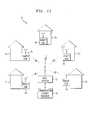
- FIG. 1Aillustrates a fixed wireless loop network according to this invention
- FIG. 1Billustrates a base station in communication with a premises communication system
- FIG. 2is a block diagram of a remote unit having detection electronics
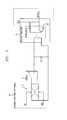
- FIG. 3is a schematic for an embodiment of the detection electronics
- FIG. 4is a flow diagram illustrating a method of operating a remote unit.
- the inventionrelates to a remote unit for use in conjunction with a communications network.
- the remote unitis positioned at a premises to act as an interface between the network and the premises communication system.
- the premises communication systemis able to receive at least one service over the network.
- the remote unitalso includes a detector for detecting whether a second network is also actively connected to the premises communication system.
- the condition in which the two (or more) networks are actively connected to the premises communication systemis referred to as a “cross-connection”.
- An actively connected networkis a network over which a service provider is enabled for providing service to the premises communication system.
- a remote unitWhen the remote unit does not detect a cross-connection, the remote unit provides the service to the premises communication system. However, when the remote unit detects a cross-connection, the remote unit withholds the service from the premises communication system. Hence, when a cross-connection exists, the premises communication system receives service from the other network without interference from the remote unit. As a result, a remote unit according to the present invention accounts for multiple service providers competing to provide services over a single premises communication system.
- FIG. 1Aillustrates a fixed wireless loop network 10 which includes a base station 12 associated with a service provider 14 .
- the service provider 14can provide services such as telephone communications, network access such as internet access, entertainment services such as television programming, etc.
- the base station 12includes a transceiver 16 for transmitting the services to a plurality of remote units 18 .
- Each remote unit 18is positioned at subscriber premises 20 such as a home, business, building, etc.
- the remote unit 18can be positioned within the premises 20 , outside the premises 20 or can be attached to a wall of the premises 20 .
- FIG. 1Billustrates a single link in the fixed wireless loop network 10 .
- a remote unit 18is positioned at subscriber premises 20 and is in communication with the premises communication system 22 .
- the premises communication system 22typically includes the wires which run through the walls of the premises 20 but can include other wired and wireless links which permit communication between the remote unit 18 and premises equipment 24 such as a telephone.
- the premises communication system 22can include connectors 26 and adapters such as telephone jacks, coaxial cable jacks and other connectors 26 which facilitate communication between the subscriber premises equipment 24 and the premises communication system 22 .
- the subscriber premises equipment 24can include telephones, fax machines, televisions, computers, modems, cameras, wires connected to the premises communication system and other items which permit the subscriber to interact with the premises communication system.
- Loop communication between the subscriber premises equipment 24 and the premises communication system 22are typically provided by ring and tip lines, although other means of loop communications are possible.
- a single item of subscriber premises equipment 24is illustrated in communication with the premises communication system 22
- a plurality of different subscriber premises equipment 24 itemscan be in communication with a single premises communication system 22 .
- many householdshave several phones, a fax machine and a modem in communication with a household communication system.
- many premisesinclude more than one premises communication system 22 so a computer and telephone can be used at the same time.
- the remote unit 18includes a subscriber network interface 28 which acts as an interface between the premises communication system 22 and the base station 12 . More specifically, the remote unit 18 provides communication between the premises communication system 22 and the base station.
- the network interface 28receives signals from the premises communication system 22 and converts these signals into a form suitable for transmission to the base station 12 .
- the network interface 28includes a transceiver 30 for transmitting the converted signals from the remote unit 18 to the base station 12 .
- the network interface 28also receives signals from the base station 12 via the transceiver 30 . The received signals are converted into signals which are loaded onto the premises communication system 22 .
- another service provider 32such as a local exchange carrier, can also be in communication with the premises communication system 22 through a Network Interface Device (NID) 34 which is typically attached to an outside wall of the premises.
- NIDNetwork Interface Device
- the other service provider 32can interfere with operation of the remote unit 18 and/or the remote unit 18 can interfere with operation of the other service provider 32 .
- This situationcan occur when the remote unit 18 is installed but the other service provider 32 is not inactivated by disconnecting the NID from the premises communication system 22 or by requesting that the other service provider 32 stop providing services.
- the first and second service providerscan actually be from the same company as can occur when a company switches mechanisms for providing services to subscribers.
- the network interface 28 in the remote unit 18includes a provider detection electronics 36 for detecting a cross-connection to or on the premises communication system 22 .
- the provider detection electronics 36can identify the connection of an LEC to the premises communication system 22 .
- the network interface 28disables the remote unit 18 so the services can be provided by the other service provider 32 without interference from the remote unit 18 .
- the remote unit 18can also include a subscriber notification mechanism 38 which notifies the subscriber of the cross-connection condition.
- a suitable subscriber notification mechanism 38includes, but is not limited to, LEDs associated with the condition, a speaker for providing an audible message and a display screen for providing a written message.
- FIG. 2is a block diagram illustrating the network interface 28 .
- the subscriber premises equipment 24is connected to a surge suppressor 42 which protects the user interface circuitry from electrical transients such as lightning strikes.
- Suitable surge suppressors 42include, but are not limited to, a TCM 1050 manufactured by Texas Instruments Corporation.
- the surge suppressor 42is connected to a subscriber line interface circuit, SLIC 44 .
- the SLIC 44supplies the premises communication system 22 with current required to operate the subscriber premises equipment 24 such as a telephone.
- a suitable SLIC 44includes, but is not limited to, a model HC55181 manufactured by Intersil in Mountaintop, Pa.
- the surge suppressor 42is also connected to provider detection electronics 36 . As described above, the provider detection electronics 36 detects the cross-connection condition.
- the SLIC 44is connected to a Codec 46 which converts analog signals from the telephone into an 8-bit digital signal.
- the Codec 46also converts 8-bit digital signals into analog signals which are provided to the premises communication system 22 where they can be received by the subscriber premises equipment 24 .
- a suitable Codec 46includes, but is not limited to, a TP 3054B PCM Codec 46 Filter manufactured by Texas Instruments.
- the Codec 46is connected to a digital signal processor, DSP 48 , which is connected to the transceiver 30 .
- the DSP 48converts signals from the Codec 46 into a form suitable for transmitting from the transceiver 30 and converts signals from the transceiver 30 to a form which is suitable for receipt by the Codec 46 .
- An interface controller 50is connected to and controls operation of both the SLIC 44 and the provider detection electronics 36 .
- a suitable controller 50includes, but is not limited to, a processor in communication with a memory such as the MPC850 manufactured by Motorola, hardware capable of performing the necessary functions and hardware, processor and memory combinations.
- the interface controller 50is connected to the subscriber notification mechanism 38 .
- the interface controller 50can operate the subscriber notification mechanism 38 to notify the subscriber that another service provider 32 is also active on the premises communication system 22 .
- FIG. 3illustrates provider detection electronics 36 which are suitable for use with the remote unit 18 described above.
- the provider detection electronics 36are connected to the tip and ring lines of a premises communication system 22 , and are preferably connected in parallel with the SLIC 44 .
- the provider detection electronics 36includes four diodes 51 arranged in a diode bridge 52 .
- the tip and ring linesare connected with the bridge 52 such that the bridge 52 provides the correct polarity to the circuit regardless of how the premises may be wired.
- An electronics activation mechanism 53such as a switch, is connected in series with the bridge 52 .
- the electronics activation mechanism 53can be connected to the interface controller 50 (shown on FIG. 2 ) such that the interface controller 50 can activate and de-activate the provider detection electronics 36 .
- a provider indicator 54 and a fifth diode 55are connected in parallel and this combination is connected in series with the electronics activation mechanism 53 .
- the provider indicator 54indicates the presence of a current in the provider detection electronics 36 .
- a suitable provider indicator 54includes, but is not limited to, an optocoupler. An optocoupler would operate by outputting a logic low when a current is present in the provider detection electronics 36 . However, when a current is not present in the provider detection electronics 36 , the optocoupler would output a logic high.
- the fifth diode 55is present to prevent electrical transients from damaging the provider indicator 54 . For instance, when the provider indicator 54 is an optocoupler, the fifth diode 55 can protect an LED in the optocoupler from electrical transients.
- the provider detection electronics 36detect cross-connection with other service providers 32 in or on the premises communication system 22 .
- the test for such cross-connectioncan be done during a power-up routine of the remote unit 18 and/or each time the subscriber uses the premises communication system 22 .
- the provider detection electronics 36can be activated. This activation can be repeated for some pre-determined number of times in order to ensure that cross-connection with another service provider 32 is not present. Once the pre-determined number of times has been exceeded without cross-connection being detected, the provider detection electronics 36 can remain inactive until the next time the remote unit 18 is powered up.
- the interface controller 50initiates detection of cross-connection with another service provider 32 by placing the SLIC 44 in a power-down mode so the SLIC 44 does not place any current on the tip and ring lines.
- the interface controller 50activates the provider detection electronics 36 .
- the provider indicator 54indicates the presence of the current.
- the provider indicator 54indicates the lack of activity on the premises communication system 22 .
- the interface controller 50receives the output from the provider indicator 54 and responds to the output based on whether is or not cross-connection is detected.
- the provider detection electronics 36can be incorporated onto the SLIC 44 or can exist as an independent unit. Alternatively, a portion of the provider detection electronics 36 can be incorporated into the SLIC 44 .
- the electronics activation mechanism 53can be incorporated into the SLIC 44 , i.e., a switch which is activated by the interface controller 50 can be included on the SLIC 44 .
- the SLIC 44 and the provider detection circuit combinationshould be replicated for each premises communication system 22 to which the remote unit 18 provides services.
- FIG. 4is a flow diagram illustrating a method for operating the remote unit 18 or an equivalent unit.
- the processbegins at step 60 when the remote unit 18 is powered up.
- decision 62a determination is made whether it is time to inquire whether another service provider 32 is present. As described above, this inquiry can be performed when the remote unit 18 is powered up and/or when the premises communication system 22 is used. Additionally, the inquiries can be performed indefinitely or can be performed a pre-determined number of times and then stopped until the remote unit 18 is powered up again.
- the processremains at decision block 62 until it is time to make an inquiry.
- any potential placed on the premises communication system 22 by the remote unit 18is removed from the premises communication system 22 at step 64 .
- the interface controller 50can remove this potential by placing the SLIC 44 in a power-down mode.
- the provider detection electronics 36are activated. These electronics can be activated by closing a switch in the provider detection electronics 36 .
- decision 68a determination is made whether there is cross-connection with another provider on the premises communication system 22 . This determination can be made by monitoring the output of the provider indicator 54 .
- a suitable provider indicator 54is an optocoupler and when the optocoupler outputs a logic low, the cross-connection condition exists and the positive exit is taken from decision 68 . When the optocoupler outputs a logic high, there is no cross-connection with another service provider 32 and the negative exit is taken.
- the interface controller 50When the negative exit is taken from decision 68 , the interface controller 50 returns the SLIC 44 to a powered up mode and the remote unit 18 provides services to the subscriber as illustrated at process block 70 .
- the interface controller 50leaves the SLIC 44 in the powered down mode and the services are provided by the other service provider 32 as illustrated at process step 72 .
- the subscriberis alerted to the activity of the other service provider 32 .
- the controller 50can activate the subscriber notification mechanism 38 . The process ends at end step 76 .
- the fixed wireless loop network described aboveis for illustrative purposes only as the remote unit 18 can be employed with networks other than fixed wireless loop networks.
- Other networkscan employ a variety of communication links in order to achieve communication between the network and a remote unit. Examples of communication links include, but are not limited to, wire communication links such as twisted pair links and coaxial cable links, fiber optic links and links employing other signal-carrying media.
- the network interface 28can be easily adapted to provide communication between these networks and the premises communication system.
- the provider detection electronics 36can be included in remote units of any network associated with cross-connection difficulties.
- set top boxes used to provide cable television servicesis an example of a remote unit 18 which can be associated with cross-connection difficulties.
- These set top boxescan be adapted to provide telephone service and/or high-speed data service in addition to television service.
- the premises communication systemIn order for the premises communication system to receive the telephone service, the set top box is connected to the premises communication system. However, if the set top box is connected without disconnecting or disabling the network which previously provided the telephone service to the premises communications system, a cross-connection will exist.
- the provider detection electronics 36can be included in the remote units of a cable service network to prevent the difficulties associated with these cross-connections.
- the provider detection electronics 36are preferably connected with the wires associated with the tip and ring lines of the premises communication system.
- the provider detection electronicscan be in communication with a controller which operates in accordance with the flow diagram illustrated in FIG. 4 . Accordingly, the remote unit/set top box of the cable service will withhold the telephone services when a cross-connection is detected and will provide the telephone services when the cross-connection is not detected.
Landscapes
- Engineering & Computer Science (AREA)
- Computer Networks & Wireless Communication (AREA)
- Signal Processing (AREA)
- Sub-Exchange Stations And Push- Button Telephones (AREA)
- Mobile Radio Communication Systems (AREA)
- Telephonic Communication Services (AREA)
Abstract
Description
Claims (30)
Priority Applications (5)
| Application Number | Priority Date | Filing Date | Title |
|---|---|---|---|
| US09/502,655US8285292B1 (en) | 2000-02-11 | 2000-02-11 | Detection of cross-connection between a wireless loop network and another loop network at a subscriber's premises |
| EP00311339AEP1124364A3 (en) | 2000-02-11 | 2000-12-18 | Detection of cross-connection between a wireless network and another loop network at a subscriber's premises |
| CA002328800ACA2328800C (en) | 2000-02-11 | 2000-12-19 | Detection of cross-connection between a wireless loop network and another loop network at a subscriber's premises |
| BR0100360-7ABR0100360A (en) | 2000-02-11 | 2001-02-05 | Cross-connection detection between a wireless loop network and another loop network in a subscriber building |
| MXPA01001429AMXPA01001429A (en) | 2000-02-11 | 2001-02-07 | Detection of cross-connection between a wireless network and another loop network at a subscriber's premises. |
Applications Claiming Priority (1)
| Application Number | Priority Date | Filing Date | Title |
|---|---|---|---|
| US09/502,655US8285292B1 (en) | 2000-02-11 | 2000-02-11 | Detection of cross-connection between a wireless loop network and another loop network at a subscriber's premises |
Publications (1)
| Publication Number | Publication Date |
|---|---|
| US8285292B1true US8285292B1 (en) | 2012-10-09 |
Family
ID=23998785
Family Applications (1)
| Application Number | Title | Priority Date | Filing Date |
|---|---|---|---|
| US09/502,655Expired - Fee RelatedUS8285292B1 (en) | 2000-02-11 | 2000-02-11 | Detection of cross-connection between a wireless loop network and another loop network at a subscriber's premises |
Country Status (5)
| Country | Link |
|---|---|
| US (1) | US8285292B1 (en) |
| EP (1) | EP1124364A3 (en) |
| BR (1) | BR0100360A (en) |
| CA (1) | CA2328800C (en) |
| MX (1) | MXPA01001429A (en) |
Citations (26)
| Publication number | Priority date | Publication date | Assignee | Title |
|---|---|---|---|---|
| US4995074A (en)* | 1989-04-03 | 1991-02-19 | Goldman Bruce J | Switched line modem interface system |
| US5610910A (en)* | 1995-08-17 | 1997-03-11 | Northern Telecom Limited | Access to telecommunications networks in multi-service environment |
| US5694430A (en) | 1989-08-14 | 1997-12-02 | Interdigital Technology Corporation | Subscriber unit for wireless digital subscriber communication system |
| US5699414A (en)* | 1994-10-03 | 1997-12-16 | Tt Systems Corporation | Method and apparatus for sharing a single telephone line between a facsimile machine, data modem, telephone answering device, and a person |
| US5734678A (en) | 1985-03-20 | 1998-03-31 | Interdigital Technology Corporation | Subscriber RF telephone system for providing multiple speech and/or data signals simultaneously over either a single or a plurality of RF channels |
| US5751789A (en)* | 1995-11-13 | 1998-05-12 | Bell Atlantic Network Services, Inc. | SNID with wireless backup |
| US5841840A (en)* | 1996-12-23 | 1998-11-24 | Paradyne Corporation | Multiple line modem and method for providing voice on demand |
| US5867510A (en) | 1997-05-30 | 1999-02-02 | Motorola, Inc. | Method of and apparatus for decoding and processing messages |
| US5956386A (en) | 1997-06-20 | 1999-09-21 | Advanced Micro Devices, Inc. | Telephone subscriber line diagnostics system and method |
| US5954799A (en)* | 1996-11-07 | 1999-09-21 | Northern Telecom Limited | Access to telecommunications networks in a multi-service environment by mapping and exchanging control message between CPE adaptors and access server |
| US5966373A (en) | 1997-12-10 | 1999-10-12 | L-3 Communications Corporation | Waveform and frame structure for a fixed wireless loop synchronous CDMA communications system |
| US5991292A (en)* | 1997-03-06 | 1999-11-23 | Nortel Networks Corporation | Network access in multi-service environment |
| US5995839A (en)* | 1996-08-20 | 1999-11-30 | Southwestern Bell Technology Resources, Inc. | Private radiotelephone system with enhanced telephone system interface |
| US6011784A (en)* | 1996-12-18 | 2000-01-04 | Motorola, Inc. | Communication system and method using asynchronous and isochronous spectrum for voice and data |
| US6081587A (en)* | 1991-11-25 | 2000-06-27 | Zoom Telephonics, Inc. | Modem with ring detection/modem processing capability |
| US6128510A (en)* | 1996-01-23 | 2000-10-03 | International Business Machines Corporation | Cordless connection for a data/fax modem |
| US6147786A (en)* | 1998-02-20 | 2000-11-14 | Nokia Telecommunications, Oy | Hybrid analog/digital WDM access network with mini-digital optical node |
| US6188764B1 (en)* | 1998-05-27 | 2001-02-13 | Actiontec Electronics, Inc. | Over-voltage protection circuit for use with a telephone appliance |
| US6256518B1 (en)* | 1997-10-10 | 2001-07-03 | At&T Corp. | System for providing power to a wireless system |
| US6259775B1 (en)* | 1997-09-05 | 2001-07-10 | Martin A. Alpert | Multi-line modem interface |
| US6345088B1 (en)* | 1999-08-11 | 2002-02-05 | Actiontec Electronics, Inc. | Apparatus and methods for handling call waiting in a modem |
| US6362908B1 (en)* | 1998-12-02 | 2002-03-26 | Marconi Communications, Inc. | Multi-service adaptable optical network unit |
| US6438384B1 (en)* | 1998-12-19 | 2002-08-20 | Qutek International Co., Ltd. | Telephone instrument with built-in modem device, and system for voice communications over the internet |
| US6526581B1 (en)* | 1999-08-03 | 2003-02-25 | Ucentric Holdings, Llc | Multi-service in-home network with an open interface |
| US6757377B1 (en)* | 1998-12-30 | 2004-06-29 | Paradyne Corporation | Central office filter system and method |
| US6912276B1 (en)* | 1999-04-12 | 2005-06-28 | Silicon Laboratories, Inc. | Modem on hold |
Family Cites Families (4)
| Publication number | Priority date | Publication date | Assignee | Title |
|---|---|---|---|---|
| US5710808A (en)* | 1993-02-25 | 1998-01-20 | Eaton; Mark William | Telephone dialling code processor |
| US5715305A (en)* | 1995-09-21 | 1998-02-03 | At&T Corp. | Apparatus for and method of providing consumers with local access carrier |
| US5673255A (en)* | 1995-12-28 | 1997-09-30 | Lucent Technologies Inc. | Apparatus for providing service to telephone subscribers connected to a remote terminal from multiple telephone service providers |
| US6118777A (en)* | 1997-10-27 | 2000-09-12 | Nortel Networks Corporation | System and method for providing competing local exchange carriers unbundled access to subscriber access lines |
- 2000
- 2000-02-11USUS09/502,655patent/US8285292B1/ennot_activeExpired - Fee Related
- 2000-12-18EPEP00311339Apatent/EP1124364A3/ennot_activeWithdrawn
- 2000-12-19CACA002328800Apatent/CA2328800C/ennot_activeExpired - Fee Related
- 2001
- 2001-02-05BRBR0100360-7Apatent/BR0100360A/ennot_activeApplication Discontinuation
- 2001-02-07MXMXPA01001429Apatent/MXPA01001429A/enactiveIP Right Grant
Patent Citations (27)
| Publication number | Priority date | Publication date | Assignee | Title |
|---|---|---|---|---|
| US5734678A (en) | 1985-03-20 | 1998-03-31 | Interdigital Technology Corporation | Subscriber RF telephone system for providing multiple speech and/or data signals simultaneously over either a single or a plurality of RF channels |
| US4995074A (en)* | 1989-04-03 | 1991-02-19 | Goldman Bruce J | Switched line modem interface system |
| US5694430A (en) | 1989-08-14 | 1997-12-02 | Interdigital Technology Corporation | Subscriber unit for wireless digital subscriber communication system |
| US6081587A (en)* | 1991-11-25 | 2000-06-27 | Zoom Telephonics, Inc. | Modem with ring detection/modem processing capability |
| US5699414A (en)* | 1994-10-03 | 1997-12-16 | Tt Systems Corporation | Method and apparatus for sharing a single telephone line between a facsimile machine, data modem, telephone answering device, and a person |
| US5610910A (en)* | 1995-08-17 | 1997-03-11 | Northern Telecom Limited | Access to telecommunications networks in multi-service environment |
| US5751789A (en)* | 1995-11-13 | 1998-05-12 | Bell Atlantic Network Services, Inc. | SNID with wireless backup |
| US6128510A (en)* | 1996-01-23 | 2000-10-03 | International Business Machines Corporation | Cordless connection for a data/fax modem |
| US5995839A (en)* | 1996-08-20 | 1999-11-30 | Southwestern Bell Technology Resources, Inc. | Private radiotelephone system with enhanced telephone system interface |
| US5954799A (en)* | 1996-11-07 | 1999-09-21 | Northern Telecom Limited | Access to telecommunications networks in a multi-service environment by mapping and exchanging control message between CPE adaptors and access server |
| US6011784A (en)* | 1996-12-18 | 2000-01-04 | Motorola, Inc. | Communication system and method using asynchronous and isochronous spectrum for voice and data |
| US5841840A (en)* | 1996-12-23 | 1998-11-24 | Paradyne Corporation | Multiple line modem and method for providing voice on demand |
| US5991292A (en)* | 1997-03-06 | 1999-11-23 | Nortel Networks Corporation | Network access in multi-service environment |
| US5867510A (en) | 1997-05-30 | 1999-02-02 | Motorola, Inc. | Method of and apparatus for decoding and processing messages |
| US5956386A (en) | 1997-06-20 | 1999-09-21 | Advanced Micro Devices, Inc. | Telephone subscriber line diagnostics system and method |
| US6259775B1 (en)* | 1997-09-05 | 2001-07-10 | Martin A. Alpert | Multi-line modem interface |
| US6256518B1 (en)* | 1997-10-10 | 2001-07-03 | At&T Corp. | System for providing power to a wireless system |
| US5966373A (en) | 1997-12-10 | 1999-10-12 | L-3 Communications Corporation | Waveform and frame structure for a fixed wireless loop synchronous CDMA communications system |
| US6147786A (en)* | 1998-02-20 | 2000-11-14 | Nokia Telecommunications, Oy | Hybrid analog/digital WDM access network with mini-digital optical node |
| US6188764B1 (en)* | 1998-05-27 | 2001-02-13 | Actiontec Electronics, Inc. | Over-voltage protection circuit for use with a telephone appliance |
| US6362908B1 (en)* | 1998-12-02 | 2002-03-26 | Marconi Communications, Inc. | Multi-service adaptable optical network unit |
| US6438384B1 (en)* | 1998-12-19 | 2002-08-20 | Qutek International Co., Ltd. | Telephone instrument with built-in modem device, and system for voice communications over the internet |
| US6757377B1 (en)* | 1998-12-30 | 2004-06-29 | Paradyne Corporation | Central office filter system and method |
| US6912276B1 (en)* | 1999-04-12 | 2005-06-28 | Silicon Laboratories, Inc. | Modem on hold |
| US6526581B1 (en)* | 1999-08-03 | 2003-02-25 | Ucentric Holdings, Llc | Multi-service in-home network with an open interface |
| US20030101459A1 (en)* | 1999-08-03 | 2003-05-29 | Ucentric Holdings, Llc | Multi-service in-home network with an open interface |
| US6345088B1 (en)* | 1999-08-11 | 2002-02-05 | Actiontec Electronics, Inc. | Apparatus and methods for handling call waiting in a modem |
Also Published As
| Publication number | Publication date |
|---|---|
| BR0100360A (en) | 2001-10-02 |
| MXPA01001429A (en) | 2002-08-06 |
| CA2328800A1 (en) | 2001-08-11 |
| EP1124364A3 (en) | 2003-10-01 |
| CA2328800C (en) | 2007-05-29 |
| EP1124364A2 (en) | 2001-08-16 |
Similar Documents
| Publication | Publication Date | Title |
|---|---|---|
| JP2926012B2 (en) | Method of accessing a home device from a data access device via a communication switching system, and a telephone switching system | |
| US5737400A (en) | Telecommunications system for accessing subscriber premises equipment using ring suppression | |
| US20070223465A1 (en) | System, method and article for VOIP and PSTN communication | |
| US5369691A (en) | Telephonic information communication method and apparatus | |
| RU2111625C1 (en) | Remote control telemetry call system | |
| US6477248B1 (en) | Multi-line station interface | |
| US8285292B1 (en) | Detection of cross-connection between a wireless loop network and another loop network at a subscriber's premises | |
| US6359972B1 (en) | Line in use detection | |
| US7372955B1 (en) | System and method for accessing a wireless network from a handset connected to a public wiring network | |
| US6697618B1 (en) | System and method for detecting failures in a wireless phone/modem jack to prevent telephone line seizures | |
| JP2002534851A (en) | System and method for power limited call processing in a communication facility | |
| US7031435B2 (en) | Method and apparatus for simultaneous line-interface wiring collision detection | |
| US20040086096A1 (en) | Public switched telephone network autosense | |
| CN101867662A (en) | High-impedance monitoring device and method for user call | |
| KR100371306B1 (en) | Subscribe telephone line state retrieval method and system | |
| JP3564017B2 (en) | Data communication method | |
| US20070223669A1 (en) | Method and apparatus for alternatively switching between phone service lines | |
| US6456713B1 (en) | Method and apparatus for detecting data port usage | |
| US20080175361A1 (en) | Apparatus and method for coextensive operation of multiple broadband services on a local network | |
| JP3816251B2 (en) | Telemetry interface gateway and communication method thereof | |
| KR100666944B1 (en) | High frequency signal removing device generated when incoming from various digital subscriber line systems | |
| JPH1188548A (en) | CATV telephone system and its terminal device | |
| KR0135491B1 (en) | Telemetering access arrangement | |
| KR200232873Y1 (en) | Structure of communication insulator | |
| WO1997037482A1 (en) | Method and apparatus for off-hook detection |
Legal Events
| Date | Code | Title | Description |
|---|---|---|---|
| AS | Assignment | Owner name:AT&T WIRELESS SERVICES, INC., WASHINGTON Free format text:ASSIGNMENT OF ASSIGNORS INTEREST;ASSIGNOR:VDOLEK, ALEX D.;REEL/FRAME:011017/0372 Effective date:20000630 | |
| AS | Assignment | Owner name:CINGULAR WIRLEESS II, LLC, GEORGIA Free format text:CERTIFICATE OF CONVERSION;ASSIGNOR:CINGULAR WIRELESS II, INC.;REEL/FRAME:017546/0612 Effective date:20041027 Owner name:CINGULAR WIRELESS II, INC., GEORGIA Free format text:ASSIGNMENT OF ASSIGNORS INTEREST;ASSIGNOR:NEW CINGULAR WIRELESS SERVICES, INC. F/K/A AT&T WIRELESS SERVICES, INC.;REEL/FRAME:017555/0711 Effective date:20041027 Owner name:CINGULAR WIRLEESS II, LLC, GEORGIA Free format text:ASSIGNMENT OF ASSIGNORS INTEREST;ASSIGNOR:CINGULAR WIRELESS II, INC.;REEL/FRAME:017546/0612 Effective date:20041027 | |
| AS | Assignment | Owner name:CINGULAR WIRELESS II, LLC, GEORGIA Free format text:CERTIFICATE OF CONVERSION;ASSIGNOR:CINGULAR WIRELESS II, INC.;REEL/FRAME:017696/0375 Effective date:20041027 | |
| AS | Assignment | Owner name:AT&T MOBILITY II, LLC, GEORGIA Free format text:CHANGE OF NAME;ASSIGNOR:CINGULAR WIRELESS II, LLC;REEL/FRAME:021315/0026 Effective date:20070420 | |
| AS | Assignment | Owner name:AT&T MOBILITY II LLC, GEORGIA Free format text:CHANGE OF NAME;ASSIGNOR:AT&T MOBILITY II, LLC;REEL/FRAME:021352/0344 Effective date:20070830 | |
| FEPP | Fee payment procedure | Free format text:PAYOR NUMBER ASSIGNED (ORIGINAL EVENT CODE: ASPN); ENTITY STATUS OF PATENT OWNER: LARGE ENTITY | |
| STCF | Information on status: patent grant | Free format text:PATENTED CASE | |
| FPAY | Fee payment | Year of fee payment:4 | |
| AS | Assignment | Owner name:DEUTSCHE BANK TRUST COMPANY AMERICAS, NEW YORK Free format text:GRANT OF FIRST PRIORITY AND JUNIOR PRIORITY SECURITY INTEREST IN PATENT RIGHTS;ASSIGNOR:CLEARWIRE IP HOLDINGS LLC;REEL/FRAME:041882/0875 Effective date:20170203 | |
| AS | Assignment | Owner name:CLEARWIRE IP HOLDINGS LLC, KANSAS Free format text:TERMINATION AND RELEASE OF FIRST PRIORITY AND JUNIOR PRIORITY SECURITY INTEREST IN PATENT RIGHTS;ASSIGNOR:DEUTSCHE BANK TRUST COMPANY AMERICAS;REEL/FRAME:052291/0439 Effective date:20200401 | |
| AS | Assignment | Owner name:DEUTSCHE BANK TRUST COMPANY AMERICAS, NEW YORK Free format text:SECURITY AGREEMENT;ASSIGNORS:T-MOBILE USA, INC.;ISBV LLC;T-MOBILE CENTRAL LLC;AND OTHERS;REEL/FRAME:053182/0001 Effective date:20200401 | |
| FEPP | Fee payment procedure | Free format text:MAINTENANCE FEE REMINDER MAILED (ORIGINAL EVENT CODE: REM.); ENTITY STATUS OF PATENT OWNER: LARGE ENTITY | |
| LAPS | Lapse for failure to pay maintenance fees | Free format text:PATENT EXPIRED FOR FAILURE TO PAY MAINTENANCE FEES (ORIGINAL EVENT CODE: EXP.); ENTITY STATUS OF PATENT OWNER: LARGE ENTITY | |
| STCH | Information on status: patent discontinuation | Free format text:PATENT EXPIRED DUE TO NONPAYMENT OF MAINTENANCE FEES UNDER 37 CFR 1.362 | |
| FP | Lapsed due to failure to pay maintenance fee | Effective date:20201009 | |
| AS | Assignment | Owner name:SPRINT SPECTRUM LLC, KANSAS Free format text:RELEASE BY SECURED PARTY;ASSIGNOR:DEUTSCHE BANK TRUST COMPANY AMERICAS;REEL/FRAME:062595/0001 Effective date:20220822 Owner name:SPRINT INTERNATIONAL INCORPORATED, KANSAS Free format text:RELEASE BY SECURED PARTY;ASSIGNOR:DEUTSCHE BANK TRUST COMPANY AMERICAS;REEL/FRAME:062595/0001 Effective date:20220822 Owner name:SPRINT COMMUNICATIONS COMPANY L.P., KANSAS Free format text:RELEASE BY SECURED PARTY;ASSIGNOR:DEUTSCHE BANK TRUST COMPANY AMERICAS;REEL/FRAME:062595/0001 Effective date:20220822 Owner name:SPRINTCOM LLC, KANSAS Free format text:RELEASE BY SECURED PARTY;ASSIGNOR:DEUTSCHE BANK TRUST COMPANY AMERICAS;REEL/FRAME:062595/0001 Effective date:20220822 Owner name:CLEARWIRE IP HOLDINGS LLC, KANSAS Free format text:RELEASE BY SECURED PARTY;ASSIGNOR:DEUTSCHE BANK TRUST COMPANY AMERICAS;REEL/FRAME:062595/0001 Effective date:20220822 Owner name:CLEARWIRE COMMUNICATIONS LLC, KANSAS Free format text:RELEASE BY SECURED PARTY;ASSIGNOR:DEUTSCHE BANK TRUST COMPANY AMERICAS;REEL/FRAME:062595/0001 Effective date:20220822 Owner name:BOOST WORLDWIDE, LLC, KANSAS Free format text:RELEASE BY SECURED PARTY;ASSIGNOR:DEUTSCHE BANK TRUST COMPANY AMERICAS;REEL/FRAME:062595/0001 Effective date:20220822 Owner name:ASSURANCE WIRELESS USA, L.P., KANSAS Free format text:RELEASE BY SECURED PARTY;ASSIGNOR:DEUTSCHE BANK TRUST COMPANY AMERICAS;REEL/FRAME:062595/0001 Effective date:20220822 Owner name:T-MOBILE USA, INC., WASHINGTON Free format text:RELEASE BY SECURED PARTY;ASSIGNOR:DEUTSCHE BANK TRUST COMPANY AMERICAS;REEL/FRAME:062595/0001 Effective date:20220822 Owner name:T-MOBILE CENTRAL LLC, WASHINGTON Free format text:RELEASE BY SECURED PARTY;ASSIGNOR:DEUTSCHE BANK TRUST COMPANY AMERICAS;REEL/FRAME:062595/0001 Effective date:20220822 Owner name:PUSHSPRING, LLC, WASHINGTON Free format text:RELEASE BY SECURED PARTY;ASSIGNOR:DEUTSCHE BANK TRUST COMPANY AMERICAS;REEL/FRAME:062595/0001 Effective date:20220822 Owner name:LAYER3 TV, LLC, WASHINGTON Free format text:RELEASE BY SECURED PARTY;ASSIGNOR:DEUTSCHE BANK TRUST COMPANY AMERICAS;REEL/FRAME:062595/0001 Effective date:20220822 Owner name:IBSV LLC, WASHINGTON Free format text:RELEASE BY SECURED PARTY;ASSIGNOR:DEUTSCHE BANK TRUST COMPANY AMERICAS;REEL/FRAME:062595/0001 Effective date:20220822 |