US8285103B2 - Fiber distribution hubs with swing frame chassis - Google Patents
Fiber distribution hubs with swing frame chassisDownload PDFInfo
- Publication number
- US8285103B2 US8285103B2US12/603,412US60341209AUS8285103B2US 8285103 B2US8285103 B2US 8285103B2US 60341209 AUS60341209 AUS 60341209AUS 8285103 B2US8285103 B2US 8285103B2
- Authority
- US
- United States
- Prior art keywords
- fiber
- pigtails
- enclosure
- distribution device
- fiber distribution
- Prior art date
- Legal status (The legal status is an assumption and is not a legal conclusion. Google has not performed a legal analysis and makes no representation as to the accuracy of the status listed.)
- Expired - Fee Related, expires
Links
Images


Classifications
- G—PHYSICS
- G02—OPTICS
- G02B—OPTICAL ELEMENTS, SYSTEMS OR APPARATUS
- G02B6/00—Light guides; Structural details of arrangements comprising light guides and other optical elements, e.g. couplings
- G02B6/24—Coupling light guides
- G02B6/36—Mechanical coupling means
- G02B6/40—Mechanical coupling means having fibre bundle mating means
- H—ELECTRICITY
- H04—ELECTRIC COMMUNICATION TECHNIQUE
- H04Q—SELECTING
- H04Q1/00—Details of selecting apparatus or arrangements
- H04Q1/02—Constructional details
- H04Q1/14—Distribution frames
- G—PHYSICS
- G02—OPTICS
- G02B—OPTICAL ELEMENTS, SYSTEMS OR APPARATUS
- G02B6/00—Light guides; Structural details of arrangements comprising light guides and other optical elements, e.g. couplings
- G02B6/24—Coupling light guides
- G02B6/36—Mechanical coupling means
- G02B6/38—Mechanical coupling means having fibre to fibre mating means
- G02B6/3807—Dismountable connectors, i.e. comprising plugs
- G02B6/3833—Details of mounting fibres in ferrules; Assembly methods; Manufacture
- G02B6/3847—Details of mounting fibres in ferrules; Assembly methods; Manufacture with means preventing fibre end damage, e.g. recessed fibre surfaces
- G02B6/3849—Details of mounting fibres in ferrules; Assembly methods; Manufacture with means preventing fibre end damage, e.g. recessed fibre surfaces using mechanical protective elements, e.g. caps, hoods, sealing membranes
- G—PHYSICS
- G02—OPTICS
- G02B—OPTICAL ELEMENTS, SYSTEMS OR APPARATUS
- G02B6/00—Light guides; Structural details of arrangements comprising light guides and other optical elements, e.g. couplings
- G02B6/44—Mechanical structures for providing tensile strength and external protection for fibres, e.g. optical transmission cables
- G02B6/4439—Auxiliary devices
- G02B6/444—Systems or boxes with surplus lengths
- G02B6/4441—Boxes
- G02B6/445—Boxes with lateral pivoting cover
- G—PHYSICS
- G02—OPTICS
- G02B—OPTICAL ELEMENTS, SYSTEMS OR APPARATUS
- G02B6/00—Light guides; Structural details of arrangements comprising light guides and other optical elements, e.g. couplings
- G02B6/44—Mechanical structures for providing tensile strength and external protection for fibres, e.g. optical transmission cables
- G02B6/4439—Auxiliary devices
- G02B6/444—Systems or boxes with surplus lengths
- G02B6/4452—Distribution frames
- G02B6/44526—Panels or rackmounts covering a whole width of the frame or rack
- G—PHYSICS
- G02—OPTICS
- G02B—OPTICAL ELEMENTS, SYSTEMS OR APPARATUS
- G02B6/00—Light guides; Structural details of arrangements comprising light guides and other optical elements, e.g. couplings
- G02B6/44—Mechanical structures for providing tensile strength and external protection for fibres, e.g. optical transmission cables
- G02B6/4439—Auxiliary devices
- G02B6/444—Systems or boxes with surplus lengths
- G02B6/44528—Patch-cords; Connector arrangements in the system or in the box
- H—ELECTRICITY
- H04—ELECTRIC COMMUNICATION TECHNIQUE
- H04B—TRANSMISSION
- H04B10/00—Transmission systems employing electromagnetic waves other than radio-waves, e.g. infrared, visible or ultraviolet light, or employing corpuscular radiation, e.g. quantum communication
- H04B10/25—Arrangements specific to fibre transmission
- H—ELECTRICITY
- H04—ELECTRIC COMMUNICATION TECHNIQUE
- H04Q—SELECTING
- H04Q1/00—Details of selecting apparatus or arrangements
- H04Q1/02—Constructional details
- H04Q1/021—Constructional details using pivoting mechanisms for accessing the interior of the apparatus
- H—ELECTRICITY
- H04—ELECTRIC COMMUNICATION TECHNIQUE
- H04Q—SELECTING
- H04Q1/00—Details of selecting apparatus or arrangements
- H04Q1/02—Constructional details
- H04Q1/11—Protection against environment
- H04Q1/114—Protection against environment flooding protection, e.g. using water proof provision
- H—ELECTRICITY
- H04—ELECTRIC COMMUNICATION TECHNIQUE
- H04Q—SELECTING
- H04Q2201/00—Constructional details of selecting arrangements
- H04Q2201/10—Housing details
- H—ELECTRICITY
- H04—ELECTRIC COMMUNICATION TECHNIQUE
- H04Q—SELECTING
- H04Q2201/00—Constructional details of selecting arrangements
- H04Q2201/80—Constructional details of selecting arrangements in specific systems
- H04Q2201/804—Constructional details of selecting arrangements in specific systems in optical transmission systems
Definitions
- the present inventionrelates generally to optical communication networks, and more particularly to devices and techniques for hinged parking of unused connectors in an enclosure used in a passive optical communications network.
- optical splittersare used to split the optical signals at various points in the network.
- Recent network specificationscall for optical splitters to be incorporated in fiber distribution hubs (FDHs) which are re-enterable outdoor enclosures. These enclosures allow easy re-entry for access to optical splitters allowing splitter ports to be utilized effectively and for additional splitter ports to be added on an incremental basis.
- FDHsfiber distribution hubs
- optical splittersare provided prepackaged in optical splitter module housings and provided with splitter outputs in pigtails that extend from the module.
- the splitter output pigtailsare typically connectorized with high performance low loss simple connector (SC) and/or LC connectors.
- SChigh performance low loss simple connector
- This optical splitter module, or cassetteprovides protective packaging for the optical splitter components in the housing and thus provides for easy handling for otherwise fragile splitter components. This approach allows the optical splitter modules to be added incrementally to the FDH, for example, as required.
- these pigtailscan sometimes be left dangling in a cable trough or raceway within the enclosure. Leaving an optical component, such as a high performance connector, exposed in an open area leaves it susceptible to damage. These high performance connectors if damaged can cause delays in service connection while connectors are repaired. Leaving connectorized splitter output pigtails dangling in a cabling trough also exposes them to dirt and debris in the cabling trough. In current network deployments it may be important to maintain clean optical connectors to maximize the performance of the network.
- fiber pigtails in the current artmay be organized in a manner that is not conducive to rapid service delivery.
- splittersmay have sixteen or thirty-two output pigtails bundled together making it difficult to find a particular pigtail.
- the bundle of loose hanging pigtailscan easily become entangled and/or damaged causing further delays in service delivery. These tangles can cause congestion and, in some cases, result in bend induced loss on the pigtails, causing lower system performance.
- FDHsmay benefit from devices and techniques that can be adapted to facilitate the organization of fiber pigtails and fiber pigtail terminations as well as protecting sensitive optical components when not in use.
- the devices and techniquesshould also facilitate easy access to pigtails and connectors so that subscribers may be efficiently connected and disconnected from the network.
- the devices and techniquesshould also group pigtails and connectors in a manner that allows them to be associated with a particular splitter module.
- a parking adaptermay include a plurality of receptacles configured to receive a like plurality of connectors, where each connector is associated with an optical fiber.
- the parking adaptermay include a dust cap post configured to receive a connector dust cap associated with at least one of the plurality of connectors.
- the parking adaptermay include a mounting device configured to removeably couple the parking adapter to a panel.
- an enclosure adapted for use in an optical communications networkmay include a first access door pivotally supported on the enclosure and adapted to facilitate access to an interior portion of the enclosure when the first access door is in an open position.
- the enclosuremay include a hinged panel adapted to reside in the interior portion of the enclosure when the first access door is in a closed position.
- the hinged panelmay also be adapted to support a parking adapter configured to receive a connector associated with an optical fiber routed in the enclosure, where the connector is received when the optical fiber is not associated with conveying an optical signal to a destination device.
- the parking adaptermay also be configured to receive a connector dust cap associated with the connector or an adapter dust cap associated with an adapter.
- the enclosuremay include a subscriber termination area adapted to provide the optical signal to the destination device.
- a method for configuring an enclosure in an optical communications networkmay include removing a connector from a parking receptacle associated with a parking adapter, where the parking adapter is associated with a hinged panel.
- the methodmay include supporting a connector dust cap on a dust cap post associated with the parking adapter, where the connector dust cap is associated with the removed connector.
- FIG. 1illustrates schematically a broadband access network, for example, a fiber-to-the-premises (FTTP) network using passive optical network (PON) components in accordance with a preferred embodiment of the present invention
- FTTPfiber-to-the-premises
- PONpassive optical network
- FIG. 2illustrates schematically further details of an FTTP network in accordance with a preferred embodiment of the present invention
- FIG. 3Aillustrates an optical splitter module in a fiber distribution network having connectorized pigtails in accordance with a preferred embodiment of the present invention
- FIG. 3Billustrates an exemplary embodiment of an optical component module in accordance with a preferred embodiment of the invention
- FIG. 4Aschematically illustrates the installation of the optical splitter module pigtails in accordance with a preferred embodiment of the present invention
- FIG. 4Bschematically illustrates the service connection configuration of the optical splitter module in accordance with a preferred embodiment of the present invention
- FIGS. 5A and 5Bschematically illustrate the installation of the optical splitter module pigtails and the service connection configuration of the optical splitter module, respectively, in a network having modules adjacent to each other in accordance with a preferred embodiment of the present invention
- FIGS. 5C and 5Dschematically illustrate the service connection configurations between adjacent fiber distribution hubs in accordance with alternate preferred embodiments of the present invention
- FIG. 6Aillustrates an embodiment of a single width splitter module along with an embodiment of a double width module in accordance with an aspect of the invention
- FIGS. 6B-6Hillustrate exemplary splitter module arrangements in accordance with an aspect of the invention
- FIGS. 7A-7Eillustrate views of the fiber distribution hub in accordance with preferred embodiments of the present invention.
- FIG. 8illustrates a view of the internal components of a fiber distribution hub enclosure in accordance with a preferred embodiment of the present invention
- FIG. 9illustrates a schematic view of a fiber distribution hub enclosure having a side-by-side equipment configuration in accordance with a preferred embodiment of the present invention
- FIG. 10illustrates an embodiment of an FDH employing a hinged chassis in accordance with an aspect of the invention
- FIG. 11Aillustrates an embodiment of an FDH utilizing a split enclosure
- FIGS. 11B-11Gillustrate various aspects and embodiments of an FDH having a split enclosure
- FIGS. 11H and 11Iillustrate an exemplary method for using an FDH enclosure having a split housing
- FIG. 12Aillustrates an embodiment of a utility pole mounted FDH having fall restraint hardware integrated therewith
- FIG. 12Billustrates a method for accessing and elevated FDH
- FIG. 13is a flow chart illustrating a method for installing and connecting optical splitter module pigtails in accordance with a preferred embodiment of the present invention
- FIG. 14Aillustrates a preferred embodiment of a single hinged parking panel for use in fiber distribution hubs
- FIG. 14Billustrates a preferred embodiment of a dual hinged parking panel for use in fiber distribution hubs
- FIG. 15illustrates an exemplary implementation of an equipment enclosure employing hinged parking
- FIG. 16illustrates an exemplary implementation of a parking adapter that may be used in conjunction with first hinged door and/or second hinged door;
- FIG. 17illustrates an exemplary parking adapter including an adapter dust cap and connector dust cap along with a parked connector having an optical fiber associated therewith;
- FIG. 18illustrates an exemplary enclosure having stationary parking adapters
- FIG. 19illustrates an exemplary method for configuring an enclosure with hinged parking
- FIG. 20illustrates an exemplary method for connecting a subscriber to an optical signal associated with an enclosure employing hinged parking.
- an optical splitter modulethat is equipped with adapters for storing connectorized optical splitter pigtail ends.
- Adaptersare administratively located on the optical splitter module bulkhead, for example, but not limited to, in octal count arrangements ideally suited to identify splitter ports having sixteen or thirty-two output ports.
- the adaptersin accordance with preferred embodiments are used to store or stage the connectorized ends of the optical splitter for rapid location, identification, easy access and removal of pigtail output ends.
- the optical splitter outputs extending from the bulkhead on the moduleare wrapped back and secured to adapters on the splitter bulkhead.
- the preferred embodimentsalso include methods for installing optical splitter modules and associated fixed length output pigtails, storing the connectorized ends of the pigtails in a position ready for deployment and then individually connecting the splitter outputs as required to connect service to subscriber terminations.
- FIG. 1illustrates, schematically, a broadband access network 10 , which for example, can be a Fiber-to-the-Premises (FTTP) network using passive optical network (PON) components in accordance with a preferred embodiment of the present invention.
- FTTPFiber-to-the-Premises
- PONpassive optical network
- FIG. 1includes an optical line terminal (OLT) 12 , a voice input 14 from a service network, a data input 16 from a service network, a video input 18 from a service network, a wavelength division multiplexed fiber 20 , a passive optical splitter 22 , an optical network terminal (ONT) 24 and 26 , a residence and an office building 28 .
- OLToptical line terminal
- ONToptical network terminal
- Network 10employs OLT 12 which receives input data streams from service networks.
- OLT 12may receive voice input 14 , data input 16 and video input 18 .
- OLT 12may then output a multiplexed data stream over one or more optical fibers 20 .
- OLT 12may output voice at a wavelength on the order of 1490 nm, data at a wavelength on the order of 1310 nm and video at a wavelength on the order of 1550 nm.
- Optical fiber 20may convey data using, for example, wavelength division multiplexing (WDM) to a passive optical splitter (POS) 22 .
- POS 22may receive data by way of a single fiber (the input fiber) and split the data across a plurality of output fibers.
- WDMwavelength division multiplexing
- POS 22passive optical splitter
- POS 22may split incoming data across 8, 16, 32, or more output fibers.
- each output fiberis associated with a respective end user such as a residential end user 27 or a commercial end user in office building 28 .
- End user locationsmay employ optical network terminals (ONTs) 24 , 26 for accepting multiplexed data and making it available to the end user.
- ONT 24may act as a demultiplexer by accepting a multiplexed data stream containing voice, video and data and demultiplexing the data stream to provide a separate voice channel to a user's telephone, a separate video channel to a television set and a separate data channel to a computer.
- the architecture described in conjunction with FIG. 1can be a point to multi-point PON construction, which utilizes, for example, 1:32 splitters at a fiber hub enclosure within a distribution area.
- the architecturecan be fiber rich 1:1 distribution between the fiber hub and a customer's premise or the architecture can be diluted 1:X where X is an integer larger than 1.
- the broadband services capability of network 10 for distributing source informationmay include, for example, data signals (622 Mbps ⁇ 155 Mbps (shared)), and video signals (860 MHz, ⁇ 600 analog and digital channels, high definition television (HDTV), and video on demand (VOD)).
- Source informationmay consist of data, such as, for example, voice or video that originates at a source such as a telecommunications service provider, hereinafter service provider.
- Network 10can include optical network terminals 26 that are scalable, provide high bandwidth, multi-service applications that serve residences and small to medium sized businesses.
- Network 10includes passive components that are located outside the plant, i.e. outside the service provider's building, and require minimal maintenance, since active components such as amplifiers are not required.
- the broadband access network 10includes digital subscriber plug-in line cards that have a broadband terminal adapter configured for receiving a digitally multiplexed broadband data stream and outputting a plurality of demultiplexed broadband data streams for the respective subscriber loops.
- FIG. 2illustrates an alternative implementation of an optical broadband access network 50 .
- Network 50may include a circuit switch/OLT 52 , an SAI, a splitter hub 54 , residential ONTs 56 , small business ONT 58 , office park ONT 60 , splitter 64 , and fiber-to-the-premises (FTTP) 62 .
- FTTPfiber-to-the-premises
- optical splitters 64are used to split the optical signals at various points in the network.
- optical splittersare typically located in both indoor and outdoor environments including a Central Office/Head End, environmentally secure cabinets, enclosures or fiber drop terminals. In some outdoor applications, optical splitters have been deployed in tightly sealed environmental enclosures that are not easily re-enterable.
- Preferred embodimentsinclude optical splitters incorporated in fiber distribution hubs 54 which are re-enterable outdoor enclosures. These enclosures allow easy re-entry by linesmen or other service personnel for access to optical splitters 64 allowing splitter ports to be utilized effectively and for additional splitter ports to be added on an incremental basis.
- Preferred embodiments of the present inventionmay receive data from optical splitters that are provided prepackaged in optical splitter module housings that are mounted in a fiber patch panel to facilitate routing of jumpers interconnected from fibers in adjacent subscriber ports to the splitter outputs.
- This optical splitter module, or cassetteprovides protective packaging and thus easy handling for otherwise fragile splitter components.
- the optical splitter modulescan be added incrementally to the patch panel.
- FTTP broadband networksare designed to achieve low optical insertion loss in order to achieve maximum network reach from electronics having fixed power output.
- Each optical component and subsystem utilized in the networkis optimized to provide minimum insertion loss.
- the optical loss budget in a preferred embodimentis approximately 23 to 25 dB with 1:32 passive splitting.
- the components and factors contributing to the optical lossinclude splitters (1:32, single or cascaded), WDMs, connectors (optical line terminal (OLT), FDF, splitters, drop, ONT), fiber attenuation (at least three wavelengths: 1310 nm, 1490 nm, 1550 nm), and splicing.
- Splitter hub 54may serve on the order of 128 splitter ports/premises. It includes multiple distribution cables, connectorized or fusion spliced between splitter and distribution hub 54 .
- the splitter hubs used in conjunction with preferred embodimentsare pole or ground mountable.
- the drop terminalscan be with or without splitters and include various number of drops, both aerial and buried.
- Splitters 64may be deployed by way of splitter hub 54 or they may be deployed in smaller enclosures.
- a fiber drop terminal 65is often used in conjunction with a utility pole 63 ( FIG. 2 ).
- Utility pole 63may be used to support conventional copper wire strands such as those used for plain old telephone service (POTS) and those used for cable television (CATV).
- POTS strandsmay consist of a plurality of twisted pairs and CATV may consist of coaxial cables.
- Utility pole 63may also support optical fiber bundles such as those used for delivering FTTP services.
- a fiber drop terminal 65may be attached to utility pole 63 and communicatively coupled with one-or-more of the optical fibers contained in a strand.
- Fiber drop terminal 65may be spliced to optical fibers using techniques known in the art. For example, fiber drop terminal 65 may be spliced to an optical fiber at a manufacturing or assembly plant at a predetermined location on a strand, or fiber drop terminal 65 may be spliced to an optical fiber in the field by a linesman, or other crafts person, at a determined location.
- Fiber drop terminalsare used to interface between distribution cables and drop cables in a Passive Optic Network (PON) application.
- the fiber drop terminal 65typically is installed by splicing a multi-fiber cable at a branch point in a large fiber count distribution cable.
- Fiber drop terminalsmay typically consist of 2, 4, 6, 8 or 12 fibers and in some instances even more fibers.
- a single cablemay be used as the input to the terminal containing the fibers with the aforementioned counts.
- a feed cablemay have a central tube housing a plurality of individual optical fibers. Inside fiber drop terminal 65 the multi-fiber feed cable is separated into individual fibers and then terminated on individual rugged outdoor connector/adapters located on the exterior surface of the enclosure.
- Fiber drop terminal 65is thus used to stage the PON cabling system near premises locations, such as a residence or office building, so that when a subscriber requests service a simple connectorized drop cable can be quickly connected between the fiber drop terminal and the Optical Network Terminal (ONT) at the home.
- ONTOptical Network Terminal
- optical connectorsare used in the network to provide the desired flexibility however they are restricted to those points in the network where flexibility is absolutely required.
- Optical connectorsare required to provide flexible access to optical splitter outputs.
- the preferred embodiments of the present inventionprovide connector flexibility and yet minimize optical loss using the optical splitter module with connectorized pigtails.
- the pigtailsmay have standard SC or LC type connectors on the ends.
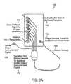
- FIG. 3Aillustrates an optical splitter module 100 in a fiber distribution network having connectorized pigtails in accordance with an exemplary embodiment.
- Module 100may include essentially any number of output pigtails; however, typical deployments will utilize either 16 or 32 outputs per splitter module.
- the module 100includes a bulkhead faceplate 102 having storage receptacles 112 .
- the optical splitter module 100provides for a high density ribbon cabling harness 106 to protect the splitter outputs extending from module 100 .
- the optical splitter module ribbon harness 106is secured to module 100 with a strain relief mechanism 104 to provide high pull strength and bend radius control.
- the compact nature of the ribbon harness 106allows for higher packing density and better space utilization in the cabling trough.
- the module harnessis converted to individual pigtails with connectors to allow splitter outputs to be administered and rearranged individually.
- Module 100may be equipped with either half non-functional adapters or full functioning adapters as a means for storing pigtail ends.
- the half non-functional adaptersare used in applications not requiring fiber optic terminators other than for storage functionality.
- the full functional adaptersare used in applications requiring connection of fiber optic terminators to the optical splitter output port. Access to the pigtail ferrule tip may be required for attaching fiber optic terminators to eliminate undesirable reflections caused by unterminated connectors.
- the moduleprovides a home position from which optical splitter output pigtails can be deployed from when placed into service and where the splitter output pigtails can be returned to once taken out of service. This administrative use of adapters provides protection for the connectorized pigtails ends, maintains cleanliness of the connector ends, and enables rapid service connection and deployment.
- the embodiments of the present inventionaddress configuring a fiber distribution hub with optical splitter modules having fixed length connectorized pigtails.
- One aspectdetermines where to position the optical splitter modules relative to other fiber terminations needing access to the optical splitter ports.
- the embodimentsalso provide for installing pigtails in a configuration that requires minimal pigtail rearrangement and slack yet allows for enough slack to reach any of the fiber terminations that require access to splitter ports.
- the methods of installing optical splitter module pigtailsinclude determining how to route the pigtails in order to provide an optimal routing scheme that does not become congested and wherein slack can be controlled within set limits of the enclosure.
- the methodsmay include making all pigtails the same length for ease of manufacturing and ordering by the customer.
- splitter modules all having the same pigtail lengthalso allow ease of flexibility for allowing a splitter module to be installed in any available slot within the patch panel without regard to sequential order. While fixed length pigtails are preferred for many applications, embodiments are not limited thereto. If desired, variable length pigtails may also be used.
- One embodiment for installing the splitter module pigtailsalso provides for fiber management in the enclosure so that rearrangement and chum does not interfere with management of the pigtails. To accomplish this, the slack and any chance of blocking access because of fiber entanglement is minimized.
- Some embodimentsallow for churn over time including initial pigtail storage, service connection, service disconnection and repeat storage to provide ready access to pigtails for future use.
- the methodcan be non-blocking and non-congesting for jumpers routed into cable pathways and fiber patch panels. The method can be fully contained within the confines of the enclosure.
- FIG. 3Billustrates a view of the optical component modules (OCM) 107 A-D in module chassis frame 101 a fiber distribution hub enclosure in accordance with an embodiment of the present invention.
- the FDH configurationprovides for fiber management hardware on one side of the cabinet. This allows fiber jumpers to be routed between the termination shelf and the splitter shelf. Excess slack can be managed on the side of the cabinet using slack loops.
- OCM modules 107 A-Dcan also be equipped with pigtails 105 to reduce the number of connections in the network.
- the modules shown in FIG. 3Bmay each contain a 1 ⁇ 32 splitter with pigtails provided on the input and 32 outputs.
- the connectorized ends of the pigtailsare stored on bulkhead adapters 103 on the front of the module. These storage adapters provide a familiar locating scheme for spare pigtails so that connector ends can be quickly identified and connected to distribution fibers.
- the spacing on the adaptersis the same as on standard connector panels.
- OCM modulescan also be equipped with standard terminators.
- Modules terminated with bulkhead adaptersmay be equipped with terminators on the front of the module.
- Modules connected via pigtails and equipped with storage adaptersare equipped with terminators on the rear of the panel.
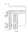
- FIG. 4Aschematically illustrates the installation of the optical splitter module pigtails 138 in accordance with an embodiment of the present invention.
- An embodiment of the present inventionincludes a cabling installation layout 125 for FDH 127 including splitter modules 132 incrementally installed on a shelf 129 adjacent to a subscriber termination field 128 .
- the connectorized pigtails 138 from the splitter modules 132 having fixed identical lengthare routed in a circumferential path 130 surrounding the subscriber termination field 128 .
- the connectorized ends of the pigtails 138are stored at a position on the front of the splitter module 132 using storage receptacles 134 .
- the layout in accordance with a preferred embodimentemploys a fan through placement so that the splitter module pigtails can be installed without disturbing installed pigtails already connected to subscriber termination field 128 .
- This installation layout in accordance with a preferred method of the present inventionalso ensures that the splitter module 132 can be preconfigured with the pigtail connectors 135 in the storage position and left in the storage position throughout the pigtail installation process.
- FIG. 4Bschematically illustrates the service connection configuration 150 of the optical splitter module in accordance with an embodiment of the present invention shown in FIG. 4A .
- the embodiments of the present inventioninclude a service connection method to connect a subscriber into service by first disconnecting an individual splitter output pigtail 138 from the storage position in splitter module 132 and then routing the pigtail to the desired subscriber port 152 . Since the pigtail harness has been preconfigured and routed circumferentially around the subscriber termination, the pigtail 138 inherently reaches any of the desired subscriber ports within the target population by simply reducing the circumferential path distance. By reducing the circumferential path the pigtail slack exhibits additional slack.
- the additional slackmay be taken up using slack-half loops in the vertical channel 153 A, B, or pigtail channel, where the pigtails are routed.
- the random nature of connecting splitter output pigtails to subscriber ports 152may result in a group of various size half-loops 154 that are managed in the vertical channel 153 A and 153 B within the confines of cabinet 149 .
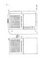
- FIGS. 5A and 5Bschematically illustrate the installation of the optical splitter module 132 pigtails and the service connection configuration of the optical splitter module 132 , respectively, in a network having modules adjacent to each other in accordance with an embodiment of the present invention.
- An embodiment of the present inventionincludes a method to connect subscriber ports that are in an adjacent field but not initially contained within the circumference of the splitter pigtail harness 178 .
- the splitter output pigtailis routed to the adjacent field 180 which by virtue of a juxtaposed position has a path at the same distance to the subscriber port within the circumference.
- the subscriber ports 192 ( FIG. 5B ) in the adjacent fieldalso are assigned randomly therefore the resultant slack is managed using a group of various size half-loops in the vertical channel 176 .
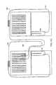
- FIGS. 5C and 5Dschematically illustrate the service connection configurations 194 , 206 of the termination and splitter fields in adjacent fiber distribution hubs in accordance with a preferred embodiment of the present invention.
- the pigtails 198 , 208 of the left module 196 , 214are routed circumferentially clockwise while the right pigtails 204 , 210 of the module 202 , 216 are routed circumferentially counterclockwise in a preferred embodiment.
- the fiber distribution hubs in this embodimentare located adjacent to one another, each having a splitter shelf with splitter modules and a termination shelf.
- the counter rotating feedprovides for routing of the splitter module output pigtails circumferentially around the subscriber termination fields.
- the pigtail slackis stored in the vertical channels 200 , 212 .
- An embodimentincludes a method of removing a splitter pigtail from a subscriber port 192 and either redeploying that output pigtail to a new subscriber port or storing the pigtail back to the original storage position at the splitter module 132 .
- the methodis non-blocking and non-congesting due to the planned slack management.
- optical splitter modules 132 used in FDH 127may have 16 output ports or 32 output ports depending on a particular network configuration which may include considerations for an optical budget associated with the optical splitters and associated network reach.
- FIG. 6Aillustrates a single width module 222 having a width (W 1 ) 230 along with a double width module 224 having a width (W 2 ) 232 that is on the order of twice that of W 1 224 .
- Optical splitter modules 222 , 224may have a physical configuration where output ports are terminated on the bulkhead faceplate 227 , 229 using connectors and/or receptacles 228 , 238 , 240 , or alternatively, with output ports in the form of pigtails 138 extending from the bulkhead faceplate and wrapped back and staged on storage ports 226 , 234 , 236 located on the faceplate as shown in, for example, FIG. 4A .
- a 16 port module 222may be deployed as a single width module W 1 230 having output ports or storage ports arranged in a single column on the faceplate 227 .
- a 32 port module 224is a double width W 2 232 module having output ports 234 or storage ports arranged in two columns of sixteen each on the faceplate 229 .
- the multi-fiber pigtail harness and associated breakout to individual pigtailsmay consume space in the enclosure to store the protective breakout device that converts from multi-fiber cables to individual fiber pigtails.
- the space for storing the breakout device, or transition, 131( FIG. 4A ) is designed to allow either breakouts from two sixteen output port modules 222 or one thirty-two output port module 224 to be used.
- the space for storing the transition 131may be located at a fixed distance along a circumferentially routed splitter output harness. Therefore the space in the chassis allocated for mounting splitter modules that corresponds to the fixed storage space for the transition 131 should allow only two sixteen output port splitter modules 222 or one thirty-two output port splitter module 224 to be installed.
- Such a configurationcan pose problems if inadequate space is provided for accommodating the transition 131 . Examples of problems that occur may include blocking and congestion.
- a pair-wise installation of a single width module 222 (e.g. a 16 output port module) in a double width slotcan be utilized to preserve correspondence of equal length cabling harness transitions 131 which are stored and secured remotely from a splitter module in a designated storage area 133 of enclosure 127 .
- Embodiments of the inventionmake use of structures and methods that alone, or in combination, dissuade a user from installing a 32 port double width module 224 immediately adjacent to a 16 port single width module 222 in situations where single width 16 port modules have not been installed in pairs, i.e. two 16 port modules installed immediately side-by-side.
- Techniques utilized in preferred embodimentsemploy an automatically indexed latch to substantially preserve pair-wise installation of single width 16 port modules in the same position as a dual width 32 port modules.
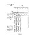
- FIG. 6Billustrates an embodiment utilizing a unique chassis bulkhead mounting configuration for splitter modules in combination with a unique latch configuration associated with the splitter module to ensure that two single-width sixteen port splitter modules 260 are installed in a pair wise arrangement into the same space that would otherwise accept a single width thirty-two port splitter module 254 .
- FIG. 6Bincludes a bulkhead 250 having an upper mounting rail 251 A and a lower rail 251 B defining an opening 257 for receiving double width splitter modules 254 and single width splitter modules 260 .
- Double width modules 254include upper mounting hole pair 256 A, lower mounting hole pair 256 B on a faceplate along with a first bank of receptacles 255 A and a second bank of receptacles 255 B.
- Single width modules 260include an upper mounting hole 261 A and a lower mounting hole 261 B and a single bank of receptacles 263 .
- single width modules 260 , and/or double width mounting modules 254may include mounting latches.
- An FDH chassisis supplied with a bulkhead 250 that provides an opening 257 for receiving splitter modules 254 , 260 in combination with mounting holes that receive splitter module latches immediately above and below the opening in the bulkhead.
- the pattern for the module mounting holes on the bulkhead of the FDH chassisconsists of four holes per double wide module 254 which is divided into two holes on top 256 A and two holes on the bottom 256 B of the opening.
- the configurationis uniquely arranged such that each set of holes is offset toward the center so that they are not spaced evenly in the center where normally they would be expected when mounting single-width 16 port modules 260 into the same space.
- This unique bulkhead mounting arrangementensures that a double width module 254 cannot be installed immediately adjacent to a single width module 260 unless two single width modules 260 have been installed in a pair wise arrangement. By ensuring a pair wise installation this in turn forces the proper utilization of the storage area for splitter output pigtail breakout devices on the FDH chassis which are located remotely from the splitter modules at a fixed distance from the splitter module along the circumferential length.
- a 16 port single-width module 260is equipped with a uniquely shaped indexing latch feature at the top and bottom of the module so that the single width module 260 can be installed into the bulkhead opening while allowing the latch to be slightly offset to the left or to the right.
- the unique latching featureis a physically shaped bilobar hole 261 A, 261 B that allows the latch of single width module to be shifted to the left or to the right upon installation to align with the off center holes.
- the slotted hole on the single-width module 260is uniquely shaped to allow a standard fastener typically used for this type of module to be fixed in place either to the left or to the right.
- This slotted holeis configured in a unique heart or bilobar shape so as to latch the fastener grommet either to the right of center when the single-width module is mounted in the left position or to the left of center when the single-width module is mounted to the right position.
- the heart shaped slotessentially indexes the latch to the left or to the right while retaining adequate strength to seat the grommet and to locate and secure the module firmly in place without subsequent shifting within the bulkhead opening.
- FIGS. 6C-6Hillustrate aspects of the keying mechanism used for aligning 16 and 32 output splitter modules in a desired pattern.
- FIGS. 7A-7Eillustrate views of a fiber distribution hub in accordance with an embodiment of the present invention.
- the FDHin accordance with an embodiment administers connections between fiber optic cables and passive optical splitters in the Outside Plant (OSP) environment. These enclosures are used to connect feeder and/or distribution cables via optical splitters to provide distributed service in a FTTP network application.
- the preferred embodiment FDHprovides a cross-connect/interconnect interface for optical transmission signals at a location in the network where fiber hubbing, operational access and reconfiguration are important requirements.
- the FDHis designed to accommodate a range of sizes and fiber counts and support factory installation of pigtails, fanouts and splitters.
- the FDHis provided in pole mount or pedestal mount configurations.
- the same cabinet and working spaceis available in both pole mount ( FIGS. 7A and 7B ) and pedestal mount units ( FIGS. 7C , 7 D and 7 E).
- Three sizes of FDHsare typically available, for example, to correspond to three different feeder counts, for example, 144, 216 and/or 432; however, additional sizes of FDHs can be used without limitation.
- Embodiments of 280 , 290 , 300 , 310 , 320 FDHprovide termination, splicing, interconnection and splitting in one compartment.
- the enclosuresaccommodate either metallic or dielectric asp cables via sealed grommet entry. Cables are secured with standard grip clamps or other means known in the art.
- the FDHmay also provide grounding for metallic members and for the cabinet.
- Enclosures 280 , 290 , 300 , 310 , 320provide environmental and mechanical protection for cables, splices, connectors and passive optical splitters. These enclosures are typically manufactured from heavy gauge aluminum and are NEMA-3R rated and provide the necessary protection against rain, wind, dust, rodents and other environmental contaminants. At the same time, these enclosures remain lightweight for easy installation, and breathable to prevent accumulation of moisture in the unit. An aluminum construction with a heavy powder coat finish also provides for corrosion resistance. These enclosures are accessible through secure doors that are locked with standard tool or pad-lock.
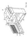
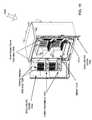
- FIG. 8illustrates a view of the internal components of a fiber distribution hub enclosure 350 in accordance with an embodiment of the present invention.
- FDH enclosure 350can be configured in a number of different ways to support fiber cable termination and interconnection to passive optical splitters.
- the configuration illustrated in FIG. 8provides for a termination shelf 352 , a splitter shelf and optical component modules 354 , a splice shelf 356 , and a channel for fiber management 358 .
- Termination shelf 352can be based on the standard main distribution center (MDC) enclosure line that provides complete management for fiber terminations in accordance with an embodiment of the present invention.
- the termination shelfmay be preterminated in the factory with a stub cable containing, for example, 72, 144, 216, 288 or 432-fibers. This stub cable is used to connect services to distribution cables routed to residences.
- the distribution fibersare terminated on certified connectors.
- the termination shelfmay use standard 12-pack or 18-pack adapter panels, for example, that have been ergonomically designed to provide easy access to fiber terminations in the field. These panels can be mounted on a hinged bulkhead to allow easy access to the rear for maintenance.
- the fiber jumpersare organized and protected as they transition into the fiber management section 358 of the enclosure.
- the splitter shelf 354can be based on a standard fiber patch panel that accepts standard optical component modules (OCM) holding optical splitters in accordance with a preferred embodiment of the present invention.
- OCMoptical component modules
- the splitter modules, or cassettesare designed to simply snap into the shelf and therefore can be added incrementally as needed.
- the splitter shelf 354serves to protect and organize the input and output fibers connected to the cassettes.
- Splitter shelves 354are available in various sizes and the shelf size can be optimized for different OCM module configurations.
- FIG. 9illustrates a schematic view of a fiber distribution hub enclosure 380 having a side-by-side equipment configuration in accordance with an embodiment of the present invention.
- FDHsmay be installed on utility poles or in pedestal arrangements that require the rear of the enclosure to remain fixed. In these situations, it is not possible to access cables or fiber terminations through the rear of the cabinet. Normal administration of an FDH may require that a linesman access the rear of the termination bulkhead to perform maintenance operations on the rear connectors. One such operation is cleaning a connector to remove dirt and/or contamination that might impair the performance of components therein. In addition, the rear of an FDH enclosure may have to be accessed for trouble shooting fibers such as may occur with fiber breakage or crushing of a fiber.
- Arrangements for providing access behind the chassismust be carefully planned so as to minimize the movement of working fibers. For instance, an arrangement may be devised to move the terminations and not the splitter pigtails. Such an arrangement may place undue stress on the terminations and/or pigtails because one section of the apparatus is moved, while another remains stationary. Apparatus that include partial movement to access connectors may not be suitable for adding additional capacity to and maintenance of, the cabling system. Sliding apparatus trays or tilting bulkhead panel apparatus may tend to create stress points in fiber cables and block certain other areas of the chassis for maintenance access, and therefore may not be a desirable alternative to enclosures having removable back panels.
- FIG. 10illustrates a preferred embodiment of an FDH enclosure 301 that is designed with a unique swing frame chassis 322 that swings the entire chassis including optical connectors, splitters and splices open 90 degrees or more to allow access to all optical components for cleaning and testing and to cables for maintenance or additions.
- the swing frame designprovides the necessary provisions to add additional cables into the unit for future use which may require complete access to the back of the cabinet. For example, access to rear penetrator punch-outs 320 is possible with the swing chassis in the opened position. Weather proof feed-throughs can be installed when the punch-outs are removed and multi-fiber cables can then be passed through the feed-throughs and into the enclosure.
- An embodiment of FDH cabinet 301may be equipped with a single point swing frame release latch 326 that provides easy access to the rear and securely locks the chassis into place when closed.
- Release latch 326may be positioned as shown in FIG. 10 and/or release latch 326 may be positioned in a lower portion of the enclosure.
- lockscan be provided to hold the chassis open at various angular increments to reduce the chances of injury to a linesman when working on components located behind the bulkhead 335 .
- Chassis 322when equipped with locks for holding it open, is referred to as a self-locking chassis.
- the entire chassisis hinged providing a single point of flex for a fiber cable routed to the chassis.
- chassis hinge 324 and cable routing hardwareare designed to ensure that manufacture recommended bend radii are not violated when the chassis is opened or closed.
- chassis 322may have pigtail channels 153 A, B attached thereto so that the slack associated with the pigtails remains fixed as chassis 322 is moved throughout its range of motion.
- transitions 131 and transition storage area 133can be located on chassis 322 .
- transitions 131may be accessed from above when chassis 322 is in an open position.
- enclosure 300may be configured at a factory, or plant, so as to have cable bundles dressed around hinge 324 . Preconfiguring enclosure 300 reduces the chance that cabling will be done incorrectly.
- enclosure 301includes, among other things, a top panel 302 , a first side panel 304 , a second side panel 306 , a bottom panel 308 , a back panel 309 , a first door 310 and a second door 312 which collectively make up the exterior dimensions and structure of the enclosure 301 .
- enclosure 301may include one or more carry handles 318 for facilitating deployment of enclosure 301 at a desired location.
- First and second doors 310 and 312may each be pivotally mounted by way of a hinged edge 313 , 315 to facilitate access to components mounted within enclosure 301 .
- first and second doors 310 , 312may employ a lip 316 and channel 314 assembly to facilitate tamper resistance and weatherproofing.
- Channel 314may operate in conjunction with elastomeric gasket material to further facilitate a weatherproof seal.
- Enclosure 301may further include ledge 307 running along an interior portion of top surface 302 , first side surface 304 , second side surface 306 and bottom surface 308 to additionally facilitate a weatherproof seal when first and second doors 312 , 314 are closed.
- a lock 311can be installed in a door to discourage unauthorized access to the interior volume of enclosure 301 .
- Enclosure 301includes a swinging frame 322 that is hinged along a side using hinge 324 .
- Hinge 324allows frame 322 to be pivoted so as to cause the side opposing hinge 324 to move away from the interior volume of enclosure 301 .
- rear feed throughs 320are accessible along with cable management tray 328 , splitter chassis rear cover 330 and rear termination connections 332 .
- the width of the chassismay have to be increased to accommodate increased termination capacity that includes an increased number of connectors, splitter modules, splices and/or fiber jumpers.
- additional issuesmay arise as the width of a swing frame FDH chassis 322 is increased.
- the width of the swing frame chassis 322As the width of the swing frame chassis 322 is increased the width of the cabinet must be increased proportionately to accommodate clearance between a swing frame chassis and the side wall of the enclosure as the chassis swings open. At a certain point the width of the entire cabinet grows beyond conventionally acceptable widths, especially for utility pole installations, when the swing frame chassis is utilized therein. While the chassis width needs to be increased to accommodate, say for example, a larger termination field, proportionally increasing the size of the swing frame chassis may not be acceptable due to the addition of even more width to the enclosure to accommodate a swinging frame.
- FIG. 11Aillustrates an embodiment of a fiber distribution hub 383 capable of accommodating large termination fields and large swinging frames associated therewith while minimizing the additional enclosure width necessary to accommodate swing frame chassis 322 .
- Hub 383may be an enclosure and may include, among other things, a rear enclosure portion 387 , a front enclosure portion 385 , a seam 381 and one or more access door panels 389 A, 389 B.
- Hub 383as illustrated, includes a first access door 389 A and a second access door 389 B.
- Hub 383includes a split enclosure designed with a seam 381 running along substantially the entire side wall, top wall, and bottom wall. Seam 381 facilitates separation of front section 385 from rear section 387 .
- Seam 381substantially splits the entire enclosure and thus provides a reduction in the overall enclosure width needed to accommodate implementations of swing frame chassis 322 . Implementations of enclosures that do not employ seam 381 may require additional width to allow clearance between the swing frame chassis and the side of the enclosure.
- the split enclosure implementation of FIG. 11Ais accomplished using a strengthened back section 387 that operates as a fixed structural member of the enclosure. Seam 381 splits the enclosure at a position along the depth to provide enough side wall stiffness to the back section 387 so as to ensure structural integrity for the entire chassis via back section 387 and a strengthened hinge 391 .
- seam 381 in the enclosuremust be sealed to protect against water and other environmental factors.
- the rear enclosure portion 387 , the front enclosure section 385 , and the chassisare joined with a compression seal via seam 381 that serves as an environmental barrier.
- hinge 391is located outside seam 381 so that a continuous seal may be routed around the enclosure.
- the entire back section 387 of the enclosuremay be covered by rain shield 393 that operates as a roof for the enclosure including the split section.
- Hinge 391is designed and configured so as to manage the bend radii of fibers in an acceptable manner.
- front enclosure portion 385 and rear enclosure portion 387are joined by two quick release latches located within the enclosure and accessed only through the front doors. These latches actuate a release that allows separation of the chassis section away from the rear enclosure portion 378 to provide access to the enclosure. The latches draw the enclosure back together and provide compression against seam 381 to provide an environmental seal.
- FDH 383may further be equipped with angled cable entry channels for carrying moisture away from the cable seals. The angled entry way, if employed, is associated with a rear section of the enclosure.
- Rear enclosure portion 387may provides a unique cable management scheme to provide rear and/or side entry. Rear entry is provided in much the same way as conventional enclosures via an angled fixture to carry moisture away from the cable seals.
- the back section of the split enclosureis designed so that the side sections are large enough to accept the same fixtures thus allowing side cable entry into the enclosure as well.
- FIGS. 11B-11Gfurther illustrate embodiments of split enclosures.
- FIG. 11Billustrates a top view of an enclosure 440 showing top surface 442 consisting of a rain shield 446 .
- FIG. 11Cillustrates a view showing rear surface 444 and utility pole mounting brackets 445 A-D.
- FIG. 11Dillustrates a side view of an enclosure showing rain shield 446 , front portion 448 , central portion 447 and rear portion 444 .
- rear portion 444remains fixed by way of being supported on, for example, a utility pole.
- Central portion 447is pivotally attached to rear portion using a hinge and front portion 448 is pivotally attached to central portion 447 using hinge 450 .
- FIG. 11Billustrates a top view of an enclosure 440 showing top surface 442 consisting of a rain shield 446 .
- FIG. 11Cillustrates a view showing rear surface 444 and utility pole mounting brackets 445 A-D.
- FIG. 11Dillustrates a side view of an enclosure showing rain
- FIG. 11Eillustrates a front view of an enclosure 441 showing, among other things, an optical splitter mounting area 456 , a subscriber termination field 458 , a cable raceway 454 and a first door 452 A and a second door 4528 .
- FIG. 11Fillustrates an enclosure 459 having rear portion 444 and gasket 450 pivotally attached to central portion 447 . Central portion 447 is in an open position and is disengaged from rear portion along, for example, three edges. Enclosure 459 may further include shelves 460 , optical splitter module mounting areas, subscriber termination fields, etc.
- FIG. 11Gillustrates a perspective view showing the rear portion of enclosure 459 . Latches 464 retain central portion 447 in a closed position.
- FIGS. 11H and 11Itogether, illustrate an exemplary method for using embodiments of FDH enclosures employing one or more swinging chassis.
- a determinationis made as to whether the enclosure utilizes a swinging chassis 322 (step 337 ). If no swinging chassis is used, the enclosure is accessed using conventional techniques known in the art (step 339 ). If a swinging chassis 322 is identified in step 337 , a determination is made as to whether the enclosure is a split enclosure (step 341 ). If the enclosure is not a split enclosure, the enclosure doors are opened (step 343 ) and the method flow goes to the input of step 351 . In contrast, if a split enclosure is identified in step 341 , the enclosure doors are opened (step 345 ) and then one-or-more compression latches are released (step 347 ).
- Compression latchesare used to keep the gasket of the enclosure in compression to facilitate weatherproofing. After the compression latches are released, the moveable portion of the enclosure is moved to its opened position (step 349 ). For example, a first section 448 and/or a central section 447 may be pivoted in an open position. After step 349 , the method flow from the No path of step 341 rejoins the main method flow.
- the swinging chassis 322is unlatched (step 351 ) and the chassis is pivoted to an open position (step 353 ).
- a desired serviceis performed (step 359 ).
- a desired servicemay include repairing damaged or worn components within the enclosure, inspecting components within the enclosure, connecting a subscriber, disconnecting a subscriber, adding additional components, such as optical splitter modules to the enclosure, and/or removing components from the enclosure.
- step 361a determination is made as to whether the chassis frame is locked in an open position (step 361 ). If the chassis is not locked in the open position, method flow goes to the input of step 365 . In contrast, if the frame is locked open, the lock is released (step 363 ). The chassis is then closed (step 365 ) and latched in the closed position (step 367 ).
- FDH enclosuresare commonly mounted to utility poles at an elevation that cannot be accessed by a linesman standing on the ground; and therefore, the linesman typically accesses the enclosure by climbing to the elevation of the enclosure.
- enclosuresare installed in conjunction with a utility platform or balcony that is a substantially permanent fixture attached to the pole below the enclosure that allows the linesman to stand in front of the enclosure while making circuit connections.
- a linesmanmay climb a ladder or steps to the elevation of the balcony and then transfer to the balcony to conduct operations.
- Standard safety procedures used in the artrequire that the linesman latch into appropriate safety mechanisms in conjunction with a safety harness to break a fall should a fall occur while climbing the ladder, transferring to the balcony, or while working on the platform. Provisions for safety latching and access are typically provided along with enclosure installations such as FDH installations.
- Enclosures fabricated for use in copper plant installationswere typically fabricated from heavy gauge steel and thus provided adequate strength for latching safety harnesses directly to the enclosure.
- new enclosuresare constructed from aluminum or other lightweight, corrosion-resistant materials to provide easier installation and to provide added protection against long term exposure to the elements. These lightweight enclosures do not provide adequate structural strength to reliably break a fall if a safety line is attached thereto.
- a linesmanmay transfer from a ladder to the platform, or balcony, to begin work on an elevated enclosure.
- Safety proceduresdictate that the linesman first attaches a safety line to an appropriate structure, herein a latching point, on the pole before making the transfer.
- the latching pointprovides necessary mobility to the linesman as he/she transfers from the ladder to the platform and while he works on the enclosure.
- a structural handlemay be provided.
- the structural handlemay be configured to support the linesman's weight as the linesman transfers from the ladder to the platform.
- the handlecan be configured to withstand loads associated with a fall.
- the latching point and handleare mounted on both sides of the pole and mounted enclosure since it cannot be determined ahead of time, with certainty, from which side of the pole the linesman will ascend to the platform.
- an elevated FDHinclude a latching point in conjunction with a structural member which can be installed as an option with a pole mounted FDH.
- Use of the optional memberallows installation of a latching point equipped FDH only in circumstances where it is desired.
- the FDHis provided with a standard mounting bracket.
- Still other embodiments of the elevated FDHprovide for a standard mounting bracket that is capable of post installation augmentation by the addition of a structural member and latching point should it be desired after an initial installation of the FDH. Since the latching point and/or structural member may incur damage if they are used to break a fall and/or over the normal course of use, embodiments of the elevated FDH utilize field-replaceable latching points and/or structural members.
- FIG. 12Aillustrates a preferred embodiment of an elevated FDH 399 mounted to a utility pole 401 using a structural member 404 having a latching point 400 .
- FDH 399may include an enclosure 403 , structural member 404 , mounting bracket 410 and lower mounting bracket 412 .
- Structural member 404may serve as stabilization member and/or mounting bracket that can optionally be equipped with a latching point 400 attached to structural member 404 .
- a handle 406can be releasably attached to the enclosure mounting bracket 410 using bolts 408 .
- the structural member 404may be constructed, for example, from a steel beam such as a welded beam and may provide adequate strength to transfer the load of an accidental fall directly to the utility pole 401 without relying on the strength of elevated FDH enclosure 403 .
- structural member 404may span substantially the entire width of the enclosure 403 .
- latching points 400are located so that a linesman can access them from the front, side, and/or back of FDH 399 .
- latching points 400are located so that a safety line can be draped over a door 414 , 416 of FDH 399 while a linesman works inside enclosure 403 .
- the latching pointconsists of a safety ring 400 made from, for example, a structurally sound “D-Ring” loop that is sized to allow fastening of the standard linesman's safety harness thereto and further having sufficient strength to restrain a linesman under accidental fall conditions.
- Latching point 400is replaceable and may be specified to be replaced after a single fall.
- the latching point 400is designed to be easily replaced using fasteners, such as bolts 401 , in conjunction with bracket 402 .
- a handle 406is also provided in the illustrated embodiment. Handle 406 may fasten onto a side of the pole mount bracket to facilitate a linesman's transfer from a ladder to a platform.
- handle 406may be mounted to a flange 410 on structural member 404 and is positioned to assist a linesman while transferring from the ladder to the pole 401 .
- a linesman climbing the pole 401will latch the safety harness to the latching point 400 , and then hold the handle 406 while transferring from the ladder to a secure position on the balcony in front of the elevated FDH enclosure.
- a typical installation of the elevated FDH 399will include a latching point 400 and a handle 406 mounted on either side of the FDH 399 .
- handle 406may be designed so that it will not accept the latch from the linesman's safety harness because handle 406 may not rated for an accidental fall load. This safety feature is achieved by increasing the diameter of handle 406 beyond a diameter that will function with the safety latch on the linesman's harness while still keeping the diameter of the handle within an acceptable range for a typical linesman to grasp. As a result, a linesman may be forced to connect the safety latch on the harness to only devices rated for a fall, such as latching point 400 .
- FIG. 12Billustrates an exemplary method for using an elevated FDH enclosure 399 equipped with a handle 406 and latching point 400 .
- the method of FIG. 12Bcommences when a linesman places a ladder against a utility pole 401 having an elevated FDH 399 mounted thereto (step 420 ). The linesman climbs the pole to the height of a balcony associated with elevated FDH 399 (step 422 ). Then the linesman attaches a safety line, rated for stopping a fall, to latching point 400 (step 424 ). The linesman then grasps handle 406 and transfers from the ladder to the balcony (step 426 ).
- the linesmanopens doors 414 and 416 to gain access to components located within an interior volume of elevated FDH 399 (step 428 ). Any necessary servicing is performed (step 430 ) and then doors 414 , 416 are closed (step 432 ). The linesman then grasps handle 406 and transfers to the ladder (step 434 ). The safety line is unclipped from the latching point 400 (step 436 ) and the linesman descends the ladder (step 438 ).
- FIG. 13is a flow chart illustrating a method for installing and connecting optical splitter module pigtails in accordance with a preferred embodiment of the present invention.
- the methodincludes the step 522 of installing a splitter module with output pigtails in a patch panel position. Further, the method includes the step 524 of routing the splitter module output pigtails circumferentially around a subscriber termination field.
- the methodincludes the step 526 of connecting an individual splitter pigtail connectorized ends at splitter module storage receptacles. These storage receptacles can initially be preconditioned in the factory.
- the methodincludes a next step 528 of storing the pigtail slack in half-loops in an adjacent vertical channel.
- the methodincludes the step 530 of deciding whether to connect or disconnect the service order. If a service order needs to be connected, the method includes the decision in step 532 of determining if a splitter output is available for assignment. If it is determined that the splitter output is available for assignment then the method progresses to step 542 of disengaging connectorized pigtail from the storage position. If it is determined that the splitter output is not available per step 538 then it is determined if a position is available for adding a module. If Yes, then the method steps are reiterated starting back from step 522 . If, however, it is determined that there is no position available then the maximum module capacity of the system has been reached.
- the methodalso includes the option of disconnecting the service order per step 530 .
- the step 534includes disengaging the connectorized pigtail from the subscriber position and per step 536 routing the pigtail through an expanded circumferential path around the subscriber termination field 536 .
- the methodfurther includes the step 544 of connecting the splitter pigtail to the subscriber position and the step 546 of routing the pigtail through a reduced circumferential path around the subscriber termination field.
- the methodincludes the step 548 of storing the pigtail slack in graduated half-loops in an adjacent vertical channel.
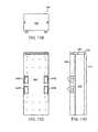
- FIG. 14Aillustrates a chassis 600 utilizing hinged parking. The embodiment of FIG.
- chassis 14Amay include, among other things, a chassis frame 602 , module retainers 603 , a splitter module mounting area 604 , an upper splitter module shelf 605 , a mounting bracket 606 for pivotally mounting chassis frame 602 and storage/parking panel 612 to an interior surface of an enclosure, an inner volume 608 , a storage panel hinge 610 , storage parking panel 612 , a parking portion having a plurality of receptacles 614 , fiber pigtail guides 616 , a fiber pigtail guide panel 618 , a storage panel primary guide 620 , and a chassis fiber guide 622 .
- Chassis frame 602has an inner volume 608 for accepting a subscriber termination field. Chassis 602 also includes a splitter module shelf 605 for supporting splitter modules above a subscriber termination field. Splitter modules are retained in place using retainers 603 . Retainer 603 may be, for example, thumb screws. Fiber pigtails having connectorized ends, are routed through chassis cable guide 622 , panel primary guide 620 , and one-or-more panel mounted fiber pigtail guides 616 before being stored in parking receptacle field 614 via a connector on a pigtail.
- Hinged storage/parking panel 612may provide greater fiber connector density than embodiments utilizing splitter modules having storage receptacles thereon, such as on an optical splitter face plate. Hinged storage/parking panel 612 may also provide greater fiber connector density than embodiments utilizing splitter modules located below a subscriber termination field.
- storage receptacles 614can be organized in columns of 16 or 32 receptacles so as to correspond to a splitter module having 16 or 32 pigtails. As pigtail connectors are removed from storage receptacles 614 and deployed onto the subscriber termination field, columns of receptacles can be removed from hinged panel 612 and re-used in FDHs at other locations.
- hinged panel 612can be removed thus providing unencumbered access to the subscriber termination field.
- hinged panel 612can be sized to serve as a protective cover for the subscriber termination field. If gasketing, or other releasable sealing means, is provided, then hinged panel 612 can operate to prevent dust and debris from accumulating on the subscriber termination field.
- FIG. 14Billustrates an embodiment of a chassis having two doors containing connector parking.
- Embodiment 650may include, among other things, a chassis 651 , an upper splitter module shelf 652 having a first module area 656 A, a second module area 656 B, a first set of module guides 654 A, a second set of module guides 654 B, a first set of module retainers 658 A, a second set of module retainers 658 B, an upper chassis fiber guide 660 A, a lower chassis fiber guide 660 B, a first door panel 662 A having a lower parking management area 666 , an upper parking management area 664 , an upper and lower parking field 668 , 670 , panel upper fiber guides 672 , panel lower fiber guides 674 , an inner volume 680 and a second door panel 662 B having substantially the same configuration as the first door panel 662 A.
- FIG. 14Boperates in substantially the same manner as the embodiment of FIG. 14A except that the receptacles for parking splitter module outputs are contained on two hinged door panels 662 A, 662 B.
- the chassis embodiments of FIGS. 14A and 14Bmay be used with enclosures mounted on grade as well as enclosures supported on utility poles.
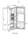
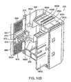
- FIG. 15illustrates an exemplary implementation of an equipment enclosure employing hinged parking.
- Enclosure 1500may include a first hinged door 1502 , a second hinged door 1504 , a first set of parking adapters 1506 , a second set of parking adapters 1508 , a first set of fiber channels 1510 , a second set of fiber channels 1512 , a first enclosure door 1514 , a second enclosure door 1516 , and a first hinge 1518 .
- Enclosure 1500may include a fiber distribution hub as previously described herein. Enclosure 1500 may be mounted on a utility pole at ground level or near the top of the utility pole. In addition, enclosure 1500 may be mounted on the ground and/or in a below grade vault. First and second enclosure doors 1514 and 1516 may serve as the primary access to the interior of enclosure 1500 . While the implementation of FIG. 15 illustrates an enclosure having two enclosure doors, other implementations may include a single enclosure door.
- Enclosure 1500may include a first hinged door 1502 and a second hinged door 1504 configured and adapted to hold one or more parking adapters.
- First and second hinged doors 1502 , 1504may be substantially flat and may include cutouts, or panel openings, for accepting parking adapters 1506 , 1508 .
- First and second hinged doors 1502 , 1504may also include fiber channels 1510 , 1512 for routing optical fibers associated with connectors that may be plugged into parking adapters 1506 , 1508 .
- First and second hinged door 1502 , 1504may be pivotally supported on enclosure 1500 and/or enclosure doors 1514 , 1516 using one or more pivoting devices, such as hinges 1518 and 1520 (not shown).
- FIG. 16illustrates an exemplary implementation of a parking adapter 1600 that may be used in conjunction with first hinged door 1502 and/or second hinged door 1504 consistent with the principles of the invention.
- Parking adapter 1600may include any device capable of receiving a connector associated with a fiber optic cable and/or an adapter dust cap.
- parking adapter 1600may be configured and adapted to receive SC connectors LC connectors, and/or other connectors known in the art.
- Parking adapter 1600may also be configured and adapted to receive SC and/or LC dust caps and/or SC or LC adapter dust caps.
- Parking adapter 1600may include 16 adapters arranged in a row and/or column; however, other implementations may include fewer adapters, more adapters, and/or adapters arranged in multiple rows and/or columns.
- Parking adapter 1600may be installed in a vertical and/or a horizontal orientation within an enclosure, such as enclosure 1500 . Parking adapters 1600 may be configured and adapted to mount without tools and/or fasteners, and/or parking adapters 1600 may be configured to mount via fasteners, such as screws, rivets, tie wraps, adhesive bonding techniques, etc.
- Parking adapter 1600may be made from plastic, metal and/or composite, via injection molding and/or machining operations.
- Parking adapter 1600may include a base 1602 , a lower engagement tab 1604 , an upper engagement hook 1606 , a dust cap post 1608 , an adapter parking receptacle 1610 .
- Parking adapter 1600may be adapted to operate with a surface, such as a panel associated with first hinged door 1502 and/or second hinged door 1504 .
- Parking adapter 1600may be supported on a panel via a lower panel opening 1612 A and/or an upper panel opening 1612 B.
- Base 1602may include a substantially flat surface that is adapted to rest against a panel, such as a door panel associated with hinged door 1502 and/or 1504 when parking adapter 1600 in installed thereon.
- Lower engagement tab 1604may be configured and adapted to engage lower panel opening 1612 A to removeably support a lower portion of parking adapter 1600 when installed on hinged door 1502 and/or 1504 .
- Upper engagement hook 1606may include any device capable of retaining an upper portion of parking adapter 1600 in a determined location.
- upper engagement hook 1606may be configured and adapted as a tensioned hook that exerts an upward force on a portion of upper panel opening 1612 B when operatively engaged therewith.
- Upper engagement hook 1606may be disengaged from hinged door 1502 and/or 1504 by applying, for example, a downward pressure while pulling the upper portion of parking adapter 1600 away from hinged door 1502 and/or 1504 .
- Substantially any number of parking adapters 1600may be positioned alongside each other to accommodate substantially any number of parked connectors and/or adapter dust caps.
- Parking adapter 1600may include one or more dust cap posts 1608 .
- Dust cap post 1608may be configured and adapted to receive a connector dust cap that has been removed from a connector associated with an optical fiber.
- dust cap post 1608may be adapted to receive an SC dust cap and/or an LC dust cap.
- Dust cap post 1608may provide a convenient location for retaining dust caps until they are needed to protect an optical fiber associated with a connector, such as when a connector is removed from a subscriber port. Implementations of dust cap post 1608 may be tapered and/or stepped to accommodate more than one type of dust cap.
- Parking adapter 1600may include one or more adapter parking receptacles 1610 that may be configured and adapted to receive a connector associated with an optical fiber, such as a fiber pigtail associated with an optical splitter.
- a connector associated with an optical fibersuch as a fiber pigtail associated with an optical splitter.
- implementations of parking adapter 1600may be configured and adapted to receive an SC and/or LC connector.
- Adapter parking receptacle 1610may be dimensioned to provide a relatively secure fit for connectors coupled thereto in order to prevent dirt and/or moisture from reaching internal portions of the connector and/or fiber housed therein.
- adapter parking receptacle 1610may be configured and dimensioned to be slightly larger that the dimensions of a connector associated with an optical fiber to as to discourage debris from passing through a gap between the receptacle surfaces and the connector surfaces.
- FIG. 17illustrates an exemplary parking adapter including an adapter dust cap and connector dust cap along with a parked connector having an optical fiber associated therewith.
- Parking adapter 1600may include a connector dust cap 1702 removeably supported on dust cap post 1608 when connector dust cap 1702 is not in use on a connector.
- Connector dust cap 1702may include SC, LC and/or other types of connector dust caps that may be used in conjunction with optical fibers.
- Parking adapter 1600may also operate with a fiber optic connector 1708 having a boot 1710 , and an optical fiber 1712 associated therewith.
- Fiber optic connector 1708 , boot 1710 and optical fiber 1712may be associated with providing service to a subscriber in conjunction with, for example, a subscriber termination shelf or field, such as subscriber termination shelf 352 ( FIG. 8 ).
- Fiber optic connector 1708may include any type of connector capable of coupling an optical signal from an optical fiber to a receptacle and/or another connector.
- Fiber optic connector 1708may include an LC, SC and/or other types of suitable connectors.
- Boot 1710may be located proximate to a transition from connector 1708 to fiber 1712 and may serve to join the connector and fiber and may also serve to manage a bend radius associated with optical fiber 1712 .
- Parking adapter 1600may include adapter parking receptacles 1610 that are configured and adapted to receive adapter dust caps 1706 when they are removed from a subscriber termination field or panel.
- an FDHmay include a subscriber termination panel that is equipped with adapter dust caps 1706 until a subscriber is connected to a source via an operational optical connection, such as by way of a fiber pigtail having a connector and optical fiber associated therewith.
- an adapter dust cap 1706 that was protecting the terminationmay be removed and placed into adapter parking receptacle 1610 .
- a connector 1708 and fiber 1712may be removed from adapter parking receptacle 1610 and connected to a subscriber termination.
- An adapter dust cap from that subscriber terminationmay be installed in the adapter parking receptacle that previously housed the connector associated with the recently connected subscriber.
- Parking adapter 1600may be removed from an enclosure when all connectors associated with the adapter are in use to convey optical signals to subscribers. When all parking adapters 1600 associated with a hinged door 1502 , 1504 are no longer in use, hinged door 1502 , 1504 may be removed and reused in another enclosure. Alternatively, hinged door 1502 , 1504 may be augmented with flat, substantially non-porous panels to prevent dust, dirt and/or moisture from reaching an interior portion of an enclosure when parking adapters 1600 are removed therefrom. Alternatively, blank hinged panels may be installed to prevent dust, dirt and/or moisture from reaching an interior portion of an enclosure when parking adapters are removed therefrom.
- FIG. 18illustrates an exemplary enclosure having stationary parking adapters.
- Enclosure 1800may include stationary adapters 1802 and a rear panel 1804 .
- Stationary adapters 1802may be configured and dimensioned substantially as parking adapter 1600 discussed in conjunction with FIGS. 16 and 17 .
- Rear panel 1804may be substantially flat and may include an upper panel opening 1808 that may be used to support a subscriber termination field and/or a lower panel opening 1810 that may be used to support one or more stationary parking adapters 1802 .
- Rear panel 1804may operate as a rear panel for an optical splitter module shelf.
- connectors associated with the splitter modulesmay be parked on one or more banks of stationary parking adapters 1802 .
- connectors associated with output pigtails 110FIG. 3A
- stationary parking adapters 1802may be removed when no longer needed for storing unused connectors. Removed stationary parking adapters 1802 may be reused in other enclosures.
- Optical fibers associated with connectors coupled to stationary parking adapter 1802may be run through guide channels 1806 .
- Guide channels 1806may manage slack associated with optical fibers in an organized manner as previously described herein.
- FIG. 19illustrates an exemplary method for configuring an enclosure with hinged parking.
- One or more hinged parking panels, or doors, 1502 , 1504may be installed in an enclosure 1500 (act 1902 ).
- Hinged parking panels 1502 , 1504may be configured to open with enclosure doors 1514 , 1516 or may be configured to open independently.
- One or more parking adapters 1600may be installed on parking panel 1502 , 1504 (act 1904 ).
- Parking adapter 1600may have a number of adapter receptacles 1610 associated therewith.
- Unassigned connectors 1708having optical fibers 1712 associated therewith, may be engaged with adapter receptacles 1610 (act 1906 ). Connectors 1708 may be stored until needed to connect service to a subscriber. Optical fibers 1712 associated with the parked connectors 1708 may be routed through fiber channels 1510 to retain the fibers in an orderly arrangement (act 1908 ). Excess fiber 1712 associated with the parked connectors 1708 may be routed through fiber channels located elsewhere in the enclosure (act 1910 ). For example, fiber channels 1510 may be configured and arranged to maintain slack in conjunction with fiber channels located elsewhere in an enclosure, such as fiber management guide 358 ( FIG.
- Fiber channels 1510may also be configured and arranged to maintain slack in desired quantities, orientations and positions to facilitate maintaining an orderly fiber arrangement within an enclosure.
- Hinged parking panel 1502may be closed after connectors 1708 are parked and excess optical fiber is placed in fiber channels 1510 (act 1912 ).
- FIG. 20illustrates an exemplary method for connecting a subscriber to an optical signal associated with an enclosure employing hinged parking.
- the methodmay commence when the enclosure door 1514 , 1516 and a hinged parking panel 1502 , 1504 are opened (act 2002 ).
- a parked connector 1708may be removed from parking adapter 1600 (act 2004 ).
- a connector dust cap 1702may be removed from the connector (act 2006 ).
- Connector dust cap 1702may be placed on dust cap post 1608 to retain the removed dust cap 1702 in a known location for future use (act 2008 ).
- An optical fiber 1712 associated with the removed connector 1708may be removed from fiber channel 1510 (act 2010 ).
- Optical fiber 1712may be routed through one or more fiber channels 1510 in the enclosure to accommodate management of excess fiber (act 2012 ).
- Adapter dust cap 1706may be removed from a subscriber termination in a subscriber termination field (act 2014 ).
- the connector 1708 that was removed from parking adapter 1600may be connected to the subscriber termination from which the adapter dust cap 1706 was removed (act 2016 ).
- communication servicesmay be available to a subscriber associated with the termination.
- the adapter dust cap 1706 that was removed from the subscriber termination in act 2014may be inserted into the parking adapter 1600 from which the connector 1708 was removed in act 2004 (act 2018 ).
- a connector and fibermay be removed from a stationary parking adapter and/or a parking adapter associated with a splitter faceplate and connected to a subscriber termination in a manner similar to that described in connection with FIG. 20 .
- an enclosuremay be configured to provide convenient parking of unused connectors and/or dust caps associated with the connectors and/or adapters.
- implementations consistent “with the principles of the inventioncan be implemented using connectors, receptacles, adapters and/or routing techniques other than those illustrated in the figures and described in the specification without departing from the spirit of the invention.
- sequence of events associated with the methods described in conjunction with FIGS. 19 and 20can be performed in orders other than those illustrated.
- additional eventscan be added, or removed, depending on specific deployments, applications, and the needs of users and/or service providers.
- disclosed implementationsmay not be limited to any specific combination of hardware circuitry and/or software.
Landscapes
- Physics & Mathematics (AREA)
- General Physics & Mathematics (AREA)
- Optics & Photonics (AREA)
- Engineering & Computer Science (AREA)
- Computer Networks & Wireless Communication (AREA)
- Health & Medical Sciences (AREA)
- Toxicology (AREA)
- Electromagnetism (AREA)
- Signal Processing (AREA)
- Light Guides In General And Applications Therefor (AREA)
- Optical Communication System (AREA)
- Mechanical Coupling Of Light Guides (AREA)
Abstract
Description
Claims (29)
Priority Applications (1)
| Application Number | Priority Date | Filing Date | Title |
|---|---|---|---|
| US12/603,412US8285103B2 (en) | 2003-11-17 | 2009-10-21 | Fiber distribution hubs with swing frame chassis |
Applications Claiming Priority (6)
| Application Number | Priority Date | Filing Date | Title |
|---|---|---|---|
| US10/714,814US6983095B2 (en) | 2003-11-17 | 2003-11-17 | Systems and methods for managing optical fibers and components within an enclosure in an optical communications network |
| US10/991,135US7200317B2 (en) | 2003-11-17 | 2004-11-17 | Systems and methods for optical fiber distribution and management |
| US67250205P | 2005-04-19 | 2005-04-19 | |
| US11/203,157US7369741B2 (en) | 2003-11-17 | 2005-08-15 | Storage adapter with dust cap posts |
| US11/820,845US7873255B2 (en) | 2003-11-17 | 2007-06-20 | Fiber distribution hubs |
| US12/603,412US8285103B2 (en) | 2003-11-17 | 2009-10-21 | Fiber distribution hubs with swing frame chassis |
Related Parent Applications (1)
| Application Number | Title | Priority Date | Filing Date |
|---|---|---|---|
| US11/820,845ContinuationUS7873255B2 (en) | 2003-11-17 | 2007-06-20 | Fiber distribution hubs |
Publications (2)
| Publication Number | Publication Date |
|---|---|
| US20100124392A1 US20100124392A1 (en) | 2010-05-20 |
| US8285103B2true US8285103B2 (en) | 2012-10-09 |
Family
ID=37037468
Family Applications (16)
| Application Number | Title | Priority Date | Filing Date |
|---|---|---|---|
| US11/203,157Expired - Fee RelatedUS7369741B2 (en) | 2003-11-17 | 2005-08-15 | Storage adapter with dust cap posts |
| US11/820,867Expired - LifetimeUS7400816B2 (en) | 2003-11-17 | 2007-06-20 | Telecommunications apparatus for distributing optical communications signals |
| US11/820,845Expired - LifetimeUS7873255B2 (en) | 2003-11-17 | 2007-06-20 | Fiber distribution hubs |
| US11/820,846Expired - LifetimeUS7471869B2 (en) | 2003-11-17 | 2007-06-20 | Equipment layout for fiber distribution hubs |
| US12/426,723Expired - LifetimeUS7844161B2 (en) | 2003-11-17 | 2009-04-20 | Parking in fiber distribution hubs |
| US12/435,181Expired - LifetimeUS7809235B2 (en) | 2003-11-17 | 2009-05-04 | Fiber distribution device |
| US12/435,170Expired - LifetimeUS7809232B2 (en) | 2003-11-17 | 2009-05-04 | Fiber distribution hub |
| US12/603,412Expired - Fee RelatedUS8285103B2 (en) | 2003-11-17 | 2009-10-21 | Fiber distribution hubs with swing frame chassis |
| US12/897,475Expired - Fee RelatedUS8374476B2 (en) | 2003-11-17 | 2010-10-04 | Fiber distribution device |
| US13/765,199Expired - Fee RelatedUS9146372B2 (en) | 2003-11-17 | 2013-02-12 | Fiber distribution device |
| US14/566,123Expired - Fee RelatedUS9146373B2 (en) | 2003-11-17 | 2014-12-10 | Fiber distribution device |
| US14/814,146Expired - Fee RelatedUS9335505B2 (en) | 2003-11-17 | 2015-07-30 | Fiber distribution device |
| US15/077,265Expired - Fee RelatedUS9739970B2 (en) | 2003-11-17 | 2016-03-22 | Fiber distribution device |
| US15/634,141Expired - Fee RelatedUS10393980B2 (en) | 2003-11-17 | 2017-06-27 | Fiber distribution device |
| US16/524,686Expired - Fee RelatedUS10782498B2 (en) | 2003-11-17 | 2019-07-29 | Fiber distribution device |
| US16/996,212Expired - LifetimeUS11579390B2 (en) | 2003-11-17 | 2020-08-18 | Fiber distribution device |
Family Applications Before (7)
| Application Number | Title | Priority Date | Filing Date |
|---|---|---|---|
| US11/203,157Expired - Fee RelatedUS7369741B2 (en) | 2003-11-17 | 2005-08-15 | Storage adapter with dust cap posts |
| US11/820,867Expired - LifetimeUS7400816B2 (en) | 2003-11-17 | 2007-06-20 | Telecommunications apparatus for distributing optical communications signals |
| US11/820,845Expired - LifetimeUS7873255B2 (en) | 2003-11-17 | 2007-06-20 | Fiber distribution hubs |
| US11/820,846Expired - LifetimeUS7471869B2 (en) | 2003-11-17 | 2007-06-20 | Equipment layout for fiber distribution hubs |
| US12/426,723Expired - LifetimeUS7844161B2 (en) | 2003-11-17 | 2009-04-20 | Parking in fiber distribution hubs |
| US12/435,181Expired - LifetimeUS7809235B2 (en) | 2003-11-17 | 2009-05-04 | Fiber distribution device |
| US12/435,170Expired - LifetimeUS7809232B2 (en) | 2003-11-17 | 2009-05-04 | Fiber distribution hub |
Family Applications After (8)
| Application Number | Title | Priority Date | Filing Date |
|---|---|---|---|
| US12/897,475Expired - Fee RelatedUS8374476B2 (en) | 2003-11-17 | 2010-10-04 | Fiber distribution device |
| US13/765,199Expired - Fee RelatedUS9146372B2 (en) | 2003-11-17 | 2013-02-12 | Fiber distribution device |
| US14/566,123Expired - Fee RelatedUS9146373B2 (en) | 2003-11-17 | 2014-12-10 | Fiber distribution device |
| US14/814,146Expired - Fee RelatedUS9335505B2 (en) | 2003-11-17 | 2015-07-30 | Fiber distribution device |
| US15/077,265Expired - Fee RelatedUS9739970B2 (en) | 2003-11-17 | 2016-03-22 | Fiber distribution device |
| US15/634,141Expired - Fee RelatedUS10393980B2 (en) | 2003-11-17 | 2017-06-27 | Fiber distribution device |
| US16/524,686Expired - Fee RelatedUS10782498B2 (en) | 2003-11-17 | 2019-07-29 | Fiber distribution device |
| US16/996,212Expired - LifetimeUS11579390B2 (en) | 2003-11-17 | 2020-08-18 | Fiber distribution device |
Country Status (6)
| Country | Link |
|---|---|
| US (16) | US7369741B2 (en) |
| EP (1) | EP1875285A2 (en) |
| KR (1) | KR20080005432A (en) |
| AU (1) | AU2006236319A1 (en) |
| CA (1) | CA2606770A1 (en) |
| WO (1) | WO2006113817A2 (en) |
Cited By (8)
| Publication number | Priority date | Publication date | Assignee | Title |
|---|---|---|---|---|
| US8847070B2 (en) | 2013-01-15 | 2014-09-30 | Channell Commercial Corporation | Grade level enclosure conversion assembly |
| US9442266B2 (en) | 2014-09-11 | 2016-09-13 | Commscope Technologies Llc | Fiber optic enclosure for retrofitting pedestals in the field |
| US9851525B2 (en) | 2014-10-06 | 2017-12-26 | Commscope Technologies Llc | Facilitating installation of fiber optic networks |
| US10031307B2 (en) | 2014-04-03 | 2018-07-24 | CommScope Connectivity Belgium BVBA | Splitter module and enclosure for use therein |
| US10107965B2 (en) | 2011-12-22 | 2018-10-23 | Commscope Technologies Llc | Fiber optic wall plate with redundancy system |
| US10663684B2 (en) | 2016-03-23 | 2020-05-26 | CommScope Connectivity Belgium BVBA | Module and enclosure for use therein |
| US10916953B2 (en)* | 2017-07-12 | 2021-02-09 | Dr. Ing. H.C. F. Porsche Aktiengesellschaft | Housing for an electricity charging station and method for producing same |
| US11169344B2 (en) | 2018-02-27 | 2021-11-09 | Commscope Technologies Llc | Common module storage within a fiber distribution hub |
Families Citing this family (227)
| Publication number | Priority date | Publication date | Assignee | Title |
|---|---|---|---|---|
| US6766950B2 (en)* | 1997-12-16 | 2004-07-27 | Donald R. Hall | Modular architecture sensing and computing platform |
| US6760531B1 (en) | 1999-03-01 | 2004-07-06 | Adc Telecommunications, Inc. | Optical fiber distribution frame with outside plant enclosure |
| US7142764B2 (en) | 2003-03-20 | 2006-11-28 | Tyco Electronics Corporation | Optical fiber interconnect cabinets, termination modules and fiber connectivity management for the same |
| US7198409B2 (en) | 2003-06-30 | 2007-04-03 | Adc Telecommunications, Inc. | Fiber optic connector holder and method |
| US6983095B2 (en)* | 2003-11-17 | 2006-01-03 | Fiber Optic Network Solutions Corporation | Systems and methods for managing optical fibers and components within an enclosure in an optical communications network |
| US7369741B2 (en) | 2003-11-17 | 2008-05-06 | Fiber Optics Network Solutions Corp. | Storage adapter with dust cap posts |
| US7218827B2 (en)* | 2004-06-18 | 2007-05-15 | Adc Telecommunications, Inc. | Multi-position fiber optic connector holder and method |
| US7167628B2 (en)* | 2004-12-13 | 2007-01-23 | Adc Telecommunications, Inc. | Service blocker device and method |
| US7194181B2 (en) | 2005-03-31 | 2007-03-20 | Adc Telecommunications, Inc. | Adapter block including connector storage |
| WO2006135524A2 (en)* | 2005-05-18 | 2006-12-21 | Corning Cable Systems Llc | High density optical fiber distribution enclosure |
| US7583883B2 (en)* | 2005-07-26 | 2009-09-01 | Adc Telecommunications, Inc. | Fiber optic connector holder |
| US7643631B2 (en)* | 2005-08-26 | 2010-01-05 | Adc Telecommunications, Inc. | Enclosure for broadband service delivery system |
| US7623749B2 (en)* | 2005-08-30 | 2009-11-24 | Adc Telecommunications, Inc. | Fiber distribution hub with modular termination blocks |
| US7330626B2 (en)* | 2005-08-31 | 2008-02-12 | Adc Telecommunications, Inc. | Cabinet including optical bulkhead plate for blown fiber system |
| US7245809B1 (en)* | 2005-12-28 | 2007-07-17 | Adc Telecommunications, Inc. | Splitter modules for fiber distribution hubs |
| US7816602B2 (en) | 2006-02-13 | 2010-10-19 | Adc Telecommunications, Inc. | Fiber distribution hub with outside accessible grounding terminals |
| US7720343B2 (en) | 2006-02-13 | 2010-05-18 | Adc Telecommunications, Inc. | Fiber distribution hub with swing frame and modular termination panels |
| US7760984B2 (en)* | 2006-05-04 | 2010-07-20 | Adc Telecommunications, Inc. | Fiber distribution hub with swing frame and wrap-around doors |
| US7711234B2 (en) | 2006-10-02 | 2010-05-04 | Adc Telecommunications, Inc. | Reskinnable fiber distribution hub |
| US7587115B1 (en) | 2006-11-30 | 2009-09-08 | Lockheed Martin Corporation | Integrated functionality in optical backplane |
| US7519258B2 (en)* | 2006-12-21 | 2009-04-14 | Corning Cable Systems Llc | Preconnectorized fiber optic local convergence points |
| US7349616B1 (en) | 2007-01-12 | 2008-03-25 | Corning Cable Systems Llc | Fiber optic local convergence points for multiple dwelling units |
| US7546018B2 (en) | 2007-01-13 | 2009-06-09 | Ofs Fitel, Llc | Fiber optic cabling for multi-dwelling unit (MDU) and commercial building deployments |
| US7400814B1 (en)* | 2007-01-13 | 2008-07-15 | Furukawa Electric North America, Inc. | Wall-mountable optical fiber and cable management apparatus |
| US7499622B2 (en)* | 2007-02-28 | 2009-03-03 | Corning Cable Systems Llc | Fiber optic drop terminals for multiple dwelling units |
| US7522805B2 (en)* | 2007-03-09 | 2009-04-21 | Adc Telecommunications, Inc. | Wall mount distribution arrangement |
| AU2011101281B4 (en)* | 2007-03-12 | 2012-01-12 | Corning Cable Systems Llc | Fiber optic local convergence points for multiple dwelling units |
| AU2011253530A1 (en)* | 2007-03-12 | 2011-12-08 | Corning Cable Systems Llc | Fiber optic local convergence points for multiple dwelling units |
| AU2011101280B4 (en)* | 2007-03-12 | 2012-01-12 | Corning Cable Systems Llc | Fiber optic local convergence points for multiple dwelling units |
| AU2011101278B4 (en)* | 2007-03-12 | 2012-02-23 | Corning Cable Systems Llc | Improved optical splitter module |
| US7409138B1 (en)* | 2007-03-12 | 2008-08-05 | Corning Cable Systems Llc | Fiber optic local convergence points for multiple dwelling units |
| US8200082B2 (en)* | 2007-03-29 | 2012-06-12 | Verizon Patent And Licensing Inc. | Fiber connectivity for emergency response personnel |
| US7734138B2 (en)* | 2007-05-30 | 2010-06-08 | Corning Cable Systems Llc | Fiber optic connector holders |
| US8385709B2 (en)* | 2007-06-01 | 2013-02-26 | Telect Inc. | Structured cabling solutions |
| US9693486B1 (en) | 2007-06-14 | 2017-06-27 | Switch, Ltd. | Air handling unit with a canopy thereover for use with a data center and method of using the same |
| US9788455B1 (en) | 2007-06-14 | 2017-10-10 | Switch, Ltd. | Electronic equipment data center or co-location facility designs and methods of making and using the same |
| US9823715B1 (en) | 2007-06-14 | 2017-11-21 | Switch, Ltd. | Data center air handling unit including uninterruptable cooling fan with weighted rotor and method of using the same |
| US10028415B1 (en) | 2007-06-14 | 2018-07-17 | Switch, Ltd. | Electronic equipment data center and server co-location facility configurations and method of using the same |
| US9622389B1 (en)* | 2007-06-14 | 2017-04-11 | Switch, Ltd. | Electronic equipment data center and server co-location facility configurations and method of using the same |
| US8523643B1 (en) | 2007-06-14 | 2013-09-03 | Switch Communications Group LLC | Electronic equipment data center or co-location facility designs and methods of making and using the same |
| EP2012155A1 (en)* | 2007-07-04 | 2009-01-07 | Nexans | Rack for optical distribution frame |
| US8798427B2 (en) | 2007-09-05 | 2014-08-05 | Corning Cable Systems Llc | Fiber optic terminal assembly |
| US7720344B2 (en)* | 2007-10-22 | 2010-05-18 | Adc Telecommunications, Inc. | Fiber distribution hub |
| US7751672B2 (en) | 2007-10-31 | 2010-07-06 | Adc Telecommunications, Inc. | Low profile fiber distribution hub |
| PL213378B1 (en)* | 2007-11-06 | 2013-02-28 | Corning Cable Systems Polska Spolka Z Ograniczona Odpowiedzialnoscia | Modular switch box for optical fibre wires and system of modular switch boxes for optical fibre wires |
| US8229265B2 (en)* | 2007-11-21 | 2012-07-24 | Adc Telecommunications, Inc. | Fiber distribution hub with multiple configurations |
| US8238709B2 (en) | 2007-12-18 | 2012-08-07 | Adc Telecommunications, Inc. | Multi-configuration mounting system for fiber distribution hub |
| US7715682B2 (en)* | 2008-03-04 | 2010-05-11 | Adc Telecommunications, Inc. | Fiber distribution hub having an adjustable plate |
| US9276673B2 (en)* | 2008-04-24 | 2016-03-01 | Commscope Technologies Llc | Methods and systems for testing a fiber optic network |
| US8444326B2 (en)* | 2008-05-30 | 2013-05-21 | 3M Innovative Properties Company | Flexible optical coupling |
| US7756380B2 (en)* | 2008-07-31 | 2010-07-13 | Commscope, Inc. Of North Carolina | Hinged cable guide panel providing access to panel rear |
| US7903922B2 (en)* | 2008-08-07 | 2011-03-08 | Fujikura Ltd. | Optical connector holder and optical termination cabinet, and method of optical fiber wiring in optical termination cabinet |
| TWI394120B (en)* | 2008-08-26 | 2013-04-21 | Au Optronics Corp | Driver integrated circuit and display substrate of flat panel display |
| ES2560802T3 (en) | 2008-08-27 | 2016-02-22 | Adc Telecommunications, Inc. | Fiber optic adapter with integrally molded bushing alignment structure |
| US11294136B2 (en) | 2008-08-29 | 2022-04-05 | Corning Optical Communications LLC | High density and bandwidth fiber optic apparatuses and related equipment and methods |
| US8452148B2 (en) | 2008-08-29 | 2013-05-28 | Corning Cable Systems Llc | Independently translatable modules and fiber optic equipment trays in fiber optic equipment |
| US20100091325A1 (en)* | 2008-10-04 | 2010-04-15 | Truetrac, Llc | Field data center |
| CN102209921B (en) | 2008-10-09 | 2015-11-25 | 康宁光缆系统有限公司 | There is the fibre-optic terminus supported from the adapter panel of the input and output optical fiber of optical splitters |
| US8879882B2 (en) | 2008-10-27 | 2014-11-04 | Corning Cable Systems Llc | Variably configurable and modular local convergence point |
| US8224144B2 (en)* | 2008-10-31 | 2012-07-17 | Tyco Electronics Corporation | Fiber optic connector storage apparatus and methods for using the same |
| WO2010059623A1 (en) | 2008-11-21 | 2010-05-27 | Adc Telecommunications, Inc. | Fiber optic telecommunications module |
| US8380036B2 (en)* | 2009-01-20 | 2013-02-19 | Adc Telecommunications, Inc. | Splitter module with connectorized pigtail manager |
| US8270845B2 (en)* | 2009-02-17 | 2012-09-18 | Gigamon Llc | Multimode fiber tap for a LRM connection |
| EP2221932B1 (en) | 2009-02-24 | 2011-11-16 | CCS Technology Inc. | Holding device for a cable or an assembly for use with a cable |
| CN106130646B (en) | 2009-03-05 | 2019-04-30 | Adc电信公司 | Methods, systems and apparatus for integrating wireless technologies into fiber optic networks |
| EP2237091A1 (en) | 2009-03-31 | 2010-10-06 | Corning Cable Systems LLC | Removably mountable fiber optic terminal |
| US8699838B2 (en) | 2009-05-14 | 2014-04-15 | Ccs Technology, Inc. | Fiber optic furcation module |
| US9075216B2 (en) | 2009-05-21 | 2015-07-07 | Corning Cable Systems Llc | Fiber optic housings configured to accommodate fiber optic modules/cassettes and fiber optic panels, and related components and methods |
| US8538226B2 (en) | 2009-05-21 | 2013-09-17 | Corning Cable Systems Llc | Fiber optic equipment guides and rails configured with stopping position(s), and related equipment and methods |
| WO2010138694A1 (en)* | 2009-05-29 | 2010-12-02 | Corning Cable Systems Llc | Dust cap assembly for sealing an optical fiber ferrule and methods thereof |
| US7899300B2 (en)* | 2009-06-03 | 2011-03-01 | Emerson Network Power, Energy Systems, North America, Inc. | Dust caps for fiber optic connectors |
| US8244089B2 (en)* | 2009-06-03 | 2012-08-14 | Emerson Network Power, Energy Systems, North America, Inc. | Dust caps for fiber optic connectors |
| EP2443497B1 (en) | 2009-06-19 | 2020-03-04 | Corning Cable Systems LLC | High density and bandwidth fiber optic apparatus |
| WO2010148325A1 (en) | 2009-06-19 | 2010-12-23 | Corning Cable Systems Llc | High fiber optic cable packing density apparatus |
| US8712206B2 (en) | 2009-06-19 | 2014-04-29 | Corning Cable Systems Llc | High-density fiber optic modules and module housings and related equipment |
| ES2403007A1 (en)* | 2009-07-01 | 2013-05-13 | Adc Telecommunications, Inc | Wall-mounted fiber distribution hub |
| US20110026930A1 (en)* | 2009-07-29 | 2011-02-03 | Zhi Cui | Methods and apparatus to upgrade communication services in subscriber distribution areas |
| WO2011025870A2 (en) | 2009-08-28 | 2011-03-03 | 3M Innovative Properties Company | Coupling field adapter |
| US8606067B2 (en)* | 2009-09-04 | 2013-12-10 | Adc Telecommunications, Inc. | Pedestal terminal with swing frame |
| US8428419B2 (en)* | 2009-09-23 | 2013-04-23 | Adc Telecommunications, Inc. | Fiber distribution hub with internal cable spool |
| US8467651B2 (en) | 2009-09-30 | 2013-06-18 | Ccs Technology Inc. | Fiber optic terminals configured to dispose a fiber optic connection panel(s) within an optical fiber perimeter and related methods |
| US20110103575A1 (en)* | 2009-10-30 | 2011-05-05 | Telect Inc. | High-density splitter/patch telecommunications system |
| US20110116239A1 (en)* | 2009-11-17 | 2011-05-19 | Emerson Network Power, Energy Systems, North America, Inc. | Locking Mechanisms for Retaining Two Swinging Panels and Apparatus and Enclosures Including a Locking Mechanism for Retaining Two Swinging Panels |
| US8208781B1 (en)* | 2009-12-03 | 2012-06-26 | Adtran, Inc. | Fiber optic connector panel |
| US20110135307A1 (en)* | 2009-12-04 | 2011-06-09 | Conner Mark E | Fiber Optic Terminals, Systems, and Methods for Network Service Management |
| US8625950B2 (en) | 2009-12-18 | 2014-01-07 | Corning Cable Systems Llc | Rotary locking apparatus for fiber optic equipment trays and related methods |
| US8992099B2 (en) | 2010-02-04 | 2015-03-31 | Corning Cable Systems Llc | Optical interface cards, assemblies, and related methods, suited for installation and use in antenna system equipment |
| CN102870021B (en) | 2010-03-02 | 2015-03-11 | 蒂安电子服务有限责任公司 | Fibre-optic telecommunication module |
| US8649649B2 (en) | 2010-03-03 | 2014-02-11 | Adc Telecommunications, Inc. | Fiber distribution hub with connectorized stub cables |
| US9547144B2 (en) | 2010-03-16 | 2017-01-17 | Corning Optical Communications LLC | Fiber optic distribution network for multiple dwelling units |
| US20110235986A1 (en)* | 2010-03-24 | 2011-09-29 | Adc Telecommunications, Inc. | Optical fiber drawer with connectorized stub cable |
| US8913866B2 (en) | 2010-03-26 | 2014-12-16 | Corning Cable Systems Llc | Movable adapter panel |
| US8837940B2 (en) | 2010-04-14 | 2014-09-16 | Adc Telecommunications, Inc. | Methods and systems for distributing fiber optic telecommunication services to local areas and for supporting distributed antenna systems |
| US9078287B2 (en) | 2010-04-14 | 2015-07-07 | Adc Telecommunications, Inc. | Fiber to the antenna |
| CA2796221C (en) | 2010-04-16 | 2018-02-13 | Ccs Technology, Inc. | Sealing and strain relief device for data cables |
| US8792767B2 (en) | 2010-04-16 | 2014-07-29 | Ccs Technology, Inc. | Distribution device |
| EP2381284B1 (en) | 2010-04-23 | 2014-12-31 | CCS Technology Inc. | Under floor fiber optic distribution device |
| US20110268408A1 (en)* | 2010-04-30 | 2011-11-03 | Giraud William J | Door fiber management for fiber optic housings, and related components and methods |
| US8705926B2 (en) | 2010-04-30 | 2014-04-22 | Corning Optical Communications LLC | Fiber optic housings having a removable top, and related components and methods |
| US9075217B2 (en) | 2010-04-30 | 2015-07-07 | Corning Cable Systems Llc | Apparatuses and related components and methods for expanding capacity of fiber optic housings |
| US9632270B2 (en) | 2010-04-30 | 2017-04-25 | Corning Optical Communications LLC | Fiber optic housings configured for tool-less assembly, and related components and methods |
| US8879881B2 (en) | 2010-04-30 | 2014-11-04 | Corning Cable Systems Llc | Rotatable routing guide and assembly |
| US9720195B2 (en) | 2010-04-30 | 2017-08-01 | Corning Optical Communications LLC | Apparatuses and related components and methods for attachment and release of fiber optic housings to and from an equipment rack |
| US8660397B2 (en) | 2010-04-30 | 2014-02-25 | Corning Cable Systems Llc | Multi-layer module |
| US9519118B2 (en) | 2010-04-30 | 2016-12-13 | Corning Optical Communications LLC | Removable fiber management sections for fiber optic housings, and related components and methods |
| WO2011140461A2 (en) | 2010-05-07 | 2011-11-10 | Adc Telecommunications, Inc. | Fiber distribution hub with pass-through interfaces |
| US9377597B2 (en)* | 2010-06-02 | 2016-06-28 | Commscope Technologies Llc | Aggregator for a switch rack system |
| US9325416B2 (en)* | 2010-07-30 | 2016-04-26 | At&T Intellectual Property I, L.P. | Network interface device for optical premises signals and networks |
| US8472773B2 (en) | 2010-08-06 | 2013-06-25 | Corning Cable Systems Llc | Fiber optic connector holder |
| US8718436B2 (en) | 2010-08-30 | 2014-05-06 | Corning Cable Systems Llc | Methods, apparatuses for providing secure fiber optic connections |
| US8274782B2 (en)* | 2010-09-30 | 2012-09-25 | Rockwell Automation Technologies, Inc. | Motor control center network connectivity method and system |
| WO2012054454A2 (en) | 2010-10-19 | 2012-04-26 | Corning Cable Systems Llc | Transition box for multiple dwelling unit fiber optic distribution network |
| US8620128B2 (en) | 2010-10-26 | 2013-12-31 | Adc Telecommunications, Inc. | System and method for anchoring fiber optic cables to provide strain relief |
| US9279951B2 (en) | 2010-10-27 | 2016-03-08 | Corning Cable Systems Llc | Fiber optic module for limited space applications having a partially sealed module sub-assembly |
| WO2012058391A1 (en) | 2010-10-28 | 2012-05-03 | Corning Cable Systems Llc | Impact resistant fiber optic enclosures and related methods |
| US9116324B2 (en) | 2010-10-29 | 2015-08-25 | Corning Cable Systems Llc | Stacked fiber optic modules and fiber optic equipment configured to support stacked fiber optic modules |
| US8662760B2 (en) | 2010-10-29 | 2014-03-04 | Corning Cable Systems Llc | Fiber optic connector employing optical fiber guide member |
| US8494332B2 (en) | 2010-11-15 | 2013-07-23 | Adc Telecommunications, Inc. | Tray assembly for a fiber optic enclosure |
| CA2819235C (en) | 2010-11-30 | 2018-01-16 | Corning Cable Systems Llc | Fiber device holder and strain relief device |
| US8873922B2 (en)* | 2010-12-20 | 2014-10-28 | Adc Telecommunications, Inc. | Fan-out and parking module |
| TWI479217B (en)* | 2010-12-29 | 2015-04-01 | Hon Hai Prec Ind Co Ltd | Optical fiber hub |
| WO2012106510A2 (en) | 2011-02-02 | 2012-08-09 | Corning Cable Systems Llc | Dense fiber optic connector assemblies and related connectors and cables suitable for establishing optical connections for optical backplanes in equipment racks |
| WO2012138440A1 (en)* | 2011-04-04 | 2012-10-11 | Afl Telecommunications Llc | Optical fiber distribution cabinet for outdoor use |
| US9008485B2 (en) | 2011-05-09 | 2015-04-14 | Corning Cable Systems Llc | Attachment mechanisms employed to attach a rear housing section to a fiber optic housing, and related assemblies and methods |
| CA2877896C (en) | 2011-06-24 | 2020-07-21 | Adc Telecommunications, Inc. | Fiber termination enclosure with modular plate assemblies |
| AU2012275598A1 (en) | 2011-06-30 | 2014-01-16 | Corning Optical Communications LLC | Fiber optic equipment assemblies employing non-U-width-sized housings and related methods |
| US20130216187A1 (en) | 2011-08-17 | 2013-08-22 | Douglas Ferris Dowling | Distributed passive optical networks |
| US8953924B2 (en) | 2011-09-02 | 2015-02-10 | Corning Cable Systems Llc | Removable strain relief brackets for securing fiber optic cables and/or optical fibers to fiber optic equipment, and related assemblies and methods |
| US20130056599A1 (en)* | 2011-09-02 | 2013-03-07 | Steven Ray Baker | Apparatus and method for toollessly, releasably attaching components to a structure |
| US9417418B2 (en) | 2011-09-12 | 2016-08-16 | Commscope Technologies Llc | Flexible lensed optical interconnect device for signal distribution |
| RU2611105C2 (en) | 2011-10-07 | 2017-02-21 | Адс Телекоммьюникейшнз, Инк. | Fibre-optic cartridge, system and method |
| US9069151B2 (en) | 2011-10-26 | 2015-06-30 | Corning Cable Systems Llc | Composite cable breakout assembly |
| US9231703B2 (en)* | 2011-11-14 | 2016-01-05 | Aci Communications, Inc. | Optical node configuration apparatus |
| US9038832B2 (en) | 2011-11-30 | 2015-05-26 | Corning Cable Systems Llc | Adapter panel support assembly |
| US9219546B2 (en) | 2011-12-12 | 2015-12-22 | Corning Optical Communications LLC | Extremely high frequency (EHF) distributed antenna systems, and related components and methods |
| WO2013130644A1 (en) | 2012-02-28 | 2013-09-06 | Centurylink Intellectual Property Llc | Apical conduit and methods of using same |
| US10110307B2 (en) | 2012-03-02 | 2018-10-23 | Corning Optical Communications LLC | Optical network units (ONUs) for high bandwidth connectivity, and related components and methods |
| US8873926B2 (en) | 2012-04-26 | 2014-10-28 | Corning Cable Systems Llc | Fiber optic enclosures employing clamping assemblies for strain relief of cables, and related assemblies and methods |
| US9004778B2 (en)* | 2012-06-29 | 2015-04-14 | Corning Cable Systems Llc | Indexable optical fiber connectors and optical fiber connector arrays |
| US9250409B2 (en) | 2012-07-02 | 2016-02-02 | Corning Cable Systems Llc | Fiber-optic-module trays and drawers for fiber-optic equipment |
| USD719102S1 (en) | 2012-07-03 | 2014-12-09 | NitroFiber, LLC | Optical fiber management cassette |
| USD753466S1 (en) | 2012-07-03 | 2016-04-12 | Nitro Fiber | Optical fiber management bracket |
| US20140036442A1 (en)* | 2012-07-31 | 2014-02-06 | Alcatel-Lucent Deutschland Ag | Outdoor stackable telecommunications equipment cabinet family with flexible thermal and interface management and method of deploying the same |
| US9049500B2 (en) | 2012-08-31 | 2015-06-02 | Corning Cable Systems Llc | Fiber optic terminals, systems, and methods for network service management |
| US9042702B2 (en) | 2012-09-18 | 2015-05-26 | Corning Cable Systems Llc | Platforms and systems for fiber optic cable attachment |
| US9146362B2 (en) | 2012-09-21 | 2015-09-29 | Adc Telecommunications, Inc. | Insertion and removal tool for a fiber optic ferrule alignment sleeve |
| US9146374B2 (en) | 2012-09-28 | 2015-09-29 | Adc Telecommunications, Inc. | Rapid deployment packaging for optical fiber |
| NZ706687A (en) | 2012-09-28 | 2017-09-29 | Adc Telecommunications Inc | Fiber optic cassette |
| US9223094B2 (en) | 2012-10-05 | 2015-12-29 | Tyco Electronics Nederland Bv | Flexible optical circuit, cassettes, and methods |
| US8909019B2 (en) | 2012-10-11 | 2014-12-09 | Ccs Technology, Inc. | System comprising a plurality of distribution devices and distribution device |
| ES2551077T3 (en) | 2012-10-26 | 2015-11-16 | Ccs Technology, Inc. | Fiber optic management unit and fiber optic distribution device |
| WO2014070511A1 (en)* | 2012-10-29 | 2014-05-08 | Adc Telecommunications, Inc. | System for testing passive optical lines |
| ES1141660Y (en) | 2012-12-19 | 2015-10-14 | Tyco Electronics Raychem Bvba | Distribution device with incrementally added dividers |
| CN103969772B (en)* | 2013-02-05 | 2016-12-28 | 泰科电子(上海)有限公司 | The support base of cable splice closure |
| WO2014134154A1 (en)* | 2013-02-26 | 2014-09-04 | Tyco Electronics Corporation | High density splitter aggregation module |
| US8985862B2 (en) | 2013-02-28 | 2015-03-24 | Corning Cable Systems Llc | High-density multi-fiber adapter housings |
| US9274300B2 (en)* | 2013-04-22 | 2016-03-01 | M2 Optics, Inc. | High density enclosure for optical modules |
| US9062423B2 (en) | 2013-03-15 | 2015-06-23 | Centurylink Intellectual Property Llc | Cast-in-place fiber technology |
| US9435975B2 (en) | 2013-03-15 | 2016-09-06 | Commscope Technologies Llc | Modular high density telecommunications frame and chassis system |
| US9606315B2 (en) | 2013-03-15 | 2017-03-28 | All Systems Broadband, Inc. | Optical fiber ribbon storage |
| US9198331B2 (en) | 2013-03-15 | 2015-11-24 | Switch, Ltd. | Data center facility design configuration |
| US9786997B2 (en) | 2013-08-01 | 2017-10-10 | Centurylink Intellectual Property Llc | Wireless access point in pedestal or hand hole |
| MX362068B (en) | 2013-08-26 | 2019-01-07 | Adc Telecommunications Inc | ARRANGEMENT OF MULTIPLEXOR WAVE DIVISION FOR SMALL CELL NETWORKS. |
| US10578825B2 (en) | 2013-09-06 | 2020-03-03 | Centurylink Intellectual Property Llc | Apical radiator |
| US9780433B2 (en) | 2013-09-06 | 2017-10-03 | Centurylink Intellectual Property Llc | Wireless distribution using cabinets, pedestals, and hand holes |
| US10330882B2 (en) | 2013-09-06 | 2019-06-25 | Centurylink Intellectual Property Llc | Apical radiator |
| US10276921B2 (en) | 2013-09-06 | 2019-04-30 | Centurylink Intellectual Property Llc | Radiating closures |
| US10154325B2 (en)* | 2014-02-12 | 2018-12-11 | Centurylink Intellectual Property Llc | Point-to-point fiber insertion |
| US10613284B2 (en) | 2013-10-18 | 2020-04-07 | Centurylink Intellectual Property Llc | Fiber-to-the-Premises (FTTP) methods and systems |
| US10774948B2 (en) | 2013-10-18 | 2020-09-15 | Centurylink Intellectual Property Llc | Apical filler layers |
| WO2015116672A1 (en) | 2014-01-28 | 2015-08-06 | Adc Telecommunications, Inc. | Slidable fiber optic connection module with cable slack management |
| US10015570B2 (en)* | 2014-02-12 | 2018-07-03 | Centurylink Intellectual Property Llc | Touchless fiber network |
| US9494758B2 (en) | 2014-04-03 | 2016-11-15 | Commscope Technologies Llc | Fiber optic distribution system |
| AU2015276109B2 (en) | 2014-06-17 | 2020-11-19 | Adc Czech Republic, S.R.O. | Cable distribution system |
| CN106575024B (en)* | 2014-06-23 | 2019-07-09 | Adc电信公司 | Undercarriage system with blades |
| CA2954629C (en) | 2014-07-09 | 2021-08-24 | Corning Optical Communications LLC | Modular optical fiber distribution hub with multi-row splitter module mounting structure |
| US9575273B2 (en)* | 2014-07-31 | 2017-02-21 | Corning Optical Communications LLC | Splitter module holder and coupler for adding additional splitter modules to optical fiber distribution hub |
| US10362710B2 (en) | 2014-10-01 | 2019-07-23 | American Products, L.L.C. | Below grade enclosure |
| US9885845B2 (en)* | 2015-01-15 | 2018-02-06 | Commscope, Inc. Of North Carolina | Module and assembly for fiber optic interconnections |
| US9742172B2 (en) | 2015-01-30 | 2017-08-22 | Centurylink Intellectual Property Llc | MediaLink interconnection box |
| US10031306B2 (en) | 2015-02-27 | 2018-07-24 | Opterna Technology Limited | Fiber distribution assemblies |
| WO2016159929A1 (en)* | 2015-03-27 | 2016-10-06 | Hewlett Packard Enterprise Development Lp | Optical fiber distribution |
| MX2017014377A (en) | 2015-05-15 | 2018-08-15 | Adc Telecommunications Shanghai Distrib Co Ltd | Alignment sleeve assembly and optical fibre adapter. |
| US9851523B2 (en) | 2015-09-22 | 2017-12-26 | Go!Foton Holdings, Inc. | Apparatus for cable routing |
| WO2017064278A1 (en)* | 2015-10-14 | 2017-04-20 | CommScope Connectivity Belgium BVBA | System for cable storage and device mounting parts |
| US9632269B1 (en)* | 2015-11-25 | 2017-04-25 | Corning Optical Communications LLC | Systems for stacking modular fiber optic cabinets, and related devices, components, and methods |
| US10606009B2 (en)* | 2015-12-01 | 2020-03-31 | CommScope Connectivity Belgium BVBA | Cable distribution system with fan out devices |
| EP3408701B1 (en) | 2016-01-28 | 2023-04-26 | CommScope Connectivity Belgium BVBA | Modular telecommunications enclosure |
| US10295771B2 (en)* | 2016-05-03 | 2019-05-21 | Corning Optical Communications LLC | Telecommunications terminal with removable modules |
| US10249103B2 (en) | 2016-08-02 | 2019-04-02 | Centurylink Intellectual Property Llc | System and method for implementing added services for OBD2 smart vehicle connection |
| US10110272B2 (en) | 2016-08-24 | 2018-10-23 | Centurylink Intellectual Property Llc | Wearable gesture control device and method |
| CA3036070A1 (en)* | 2016-09-06 | 2018-03-15 | Corning Research And Development Corporation | Fiber optic splitter terminal for a distributed-split fiber optic distribution network |
| WO2018053200A1 (en) | 2016-09-14 | 2018-03-22 | Switch, Ltd. | Ventilation and air flow control |
| MX2019002984A (en) | 2016-09-16 | 2019-08-14 | Corning Res And Development Corporation | PARKING DOOR ASSEMBLIES FOR USE WITH FIBER DISTRIBUTION CENTERS AND METHODS TO INSTALL PARKING DOORS. |
| US10687377B2 (en) | 2016-09-20 | 2020-06-16 | Centurylink Intellectual Property Llc | Universal wireless station for multiple simultaneous wireless services |
| CN109923456B (en)* | 2016-09-30 | 2021-02-19 | 英国电讯有限公司 | Optical fiber connector and communication network including the same |
| EP3523687B1 (en)* | 2016-10-05 | 2023-09-27 | CommScope Connectivity Belgium BVBA | Telecommunications system and methods |
| US10222773B2 (en) | 2016-12-23 | 2019-03-05 | Centurylink Intellectual Property Llc | System, apparatus, and method for implementing one or more internet of things (IoT) capable devices embedded within a roadway structure for performing various tasks |
| US10193981B2 (en) | 2016-12-23 | 2019-01-29 | Centurylink Intellectual Property Llc | Internet of things (IoT) self-organizing network |
| US10150471B2 (en) | 2016-12-23 | 2018-12-11 | Centurylink Intellectual Property Llc | Smart vehicle apparatus, system, and method |
| US10146024B2 (en) | 2017-01-10 | 2018-12-04 | Centurylink Intellectual Property Llc | Apical conduit method and system |
| US10520693B2 (en) | 2017-02-09 | 2019-12-31 | Corning Research & Development Corporation | Pre-mounted fiber optic distribution cabinet assembly |
| US10530497B2 (en)* | 2017-03-15 | 2020-01-07 | Methode Electronics, Inc. | Distribution point unit for high speed communications node |
| US10310206B2 (en) | 2017-05-22 | 2019-06-04 | Go!Foton Holdings, Inc. | Apparatus for cable routing |
| US10935745B1 (en) | 2017-07-20 | 2021-03-02 | Forrest Tyrone Gay | Multi-carrier fiber distribution hub |
| US11274990B2 (en) | 2017-07-20 | 2022-03-15 | British Telecommunications Public Limited Company | Optical fiber |
| US11409068B2 (en) | 2017-10-02 | 2022-08-09 | Commscope Technologies Llc | Fiber optic circuit and preparation method |
| US10591692B2 (en)* | 2017-12-27 | 2020-03-17 | Afl Ig Llc | Optical distribution frames |
| TWM560137U (en)* | 2018-01-30 | 2018-05-11 | 大陸商安費諾光纖技術(深圳)有限公司 | Fiber optic adapter |
| CN110557522A (en)* | 2018-05-31 | 2019-12-10 | 阿里巴巴集团控股有限公司 | Method and device for removing video jitter |
| CN109001877B (en)* | 2018-07-05 | 2020-03-13 | 江苏通鼎宽带有限公司 | Optical cable distributing box and automatic jumper connection system thereof |
| WO2020046681A1 (en)* | 2018-08-29 | 2020-03-05 | Commscope Technologies Llc | Indexing cable arrangement and enclosure for use therewith |
| CN109901271B (en)* | 2019-04-03 | 2020-08-11 | 杭州富阳宏扬光电设备有限公司 | High-capacity optical cable fiber distribution box |
| US11333841B2 (en)* | 2019-05-01 | 2022-05-17 | Corning Research & Development Corporation | Fiber transition housing with optical connection features |
| US11269152B2 (en)* | 2019-09-18 | 2022-03-08 | Corning Research & Development Corporation | Structured fiber optic cabling system including adapter modules and orthogonally arranged jumper assemblies |
| WO2021055779A1 (en) | 2019-09-20 | 2021-03-25 | Commscope Technologies Llc | Powered fiber distribution hub |
| CN110650380A (en)* | 2019-09-24 | 2020-01-03 | 苏州南师大科技园投资管理有限公司 | A temporary wireless communication relay device |
| WO2021071844A1 (en)* | 2019-10-07 | 2021-04-15 | Commscope Technologies Llc | Fiber distribution hub including sealed splice module |
| US12339511B2 (en) | 2020-03-31 | 2025-06-24 | Commscope Technologies Llc | Fiber optic cable management systems and methods |
| EP4143859A4 (en)* | 2020-04-29 | 2024-05-15 | CTC Global Corporation | Strength member assemblies and overhead electrical cables incorporating optical fibers |
| US11971580B2 (en)* | 2020-09-04 | 2024-04-30 | Ppc Broadband, Inc. | Fiber optic storage devices for fiber distribution hubs |
| US11391894B1 (en) | 2021-11-11 | 2022-07-19 | Frontier Communications Holdings, Llc | Passive optical couplers having passive optical activity indicators and methods of operating the same |
| US11350061B1 (en) | 2021-11-11 | 2022-05-31 | Frontier Communications Holdings, Llc | Systems and methods for collecting information regarding optical connections in a fiber distribution hub of a passive optical network |
| US11356177B1 (en)* | 2021-11-11 | 2022-06-07 | Frontier Communications Holdings, Llc | Systems and methods for mapping optical connections in a fiber distribution hub of a passive optical network |
| CN114236723B (en)* | 2021-12-21 | 2024-08-13 | 宁波盈科光通信科技有限公司 | High-density optical fiber distribution frame |
| NL2031468B1 (en) | 2022-03-31 | 2023-10-24 | B V Twentsche Kabelfabriek | Parking device, distribution frame and method for parking a patch cord |
| WO2024096912A1 (en)* | 2022-11-06 | 2024-05-10 | Lumeda Inc. | Multi-port connector cable panel |
Citations (132)
| Publication number | Priority date | Publication date | Assignee | Title |
|---|---|---|---|---|
| US4736100A (en) | 1986-07-31 | 1988-04-05 | Amp Incorporated | Optical loop attenuator simulating an optical system |
| US4747020A (en) | 1986-05-16 | 1988-05-24 | Adc Telecommunications, Inc. | Wire distribution apparatus |
| US4792203A (en) | 1985-09-17 | 1988-12-20 | Adc Telecommunications, Inc. | Optical fiber distribution apparatus |
| US4824196A (en) | 1987-05-26 | 1989-04-25 | Minnesota Mining And Manufacturing Company | Optical fiber distribution panel |
| US4861134A (en) | 1988-06-29 | 1989-08-29 | American Telephone And Telegraph Company, At&T Bell Laboratories | Opto-electronic and optical fiber interface arrangement |
| US4900123A (en) | 1988-08-29 | 1990-02-13 | Gte Products Corporation | 1550 nm fiber distribution panel |
| US4948220A (en) | 1988-06-20 | 1990-08-14 | Societe Anonyme De Telecommunications | Module for distributing and connecting optical fibers |
| US4995688A (en) | 1989-07-31 | 1991-02-26 | Adc Telecommunications, Inc. | Optical fiber distribution frame |
| US5023646A (en) | 1985-12-27 | 1991-06-11 | Minolta Camera Kabushiki Kaisha | Automatic focus detection system |
| US5058983A (en) | 1990-07-06 | 1991-10-22 | Aster Corporation | Fiber optic connector terminator |
| US5073042A (en) | 1990-06-21 | 1991-12-17 | Amp Incorporated | Coupling bushing for various types of optical fiber connectors |
| US5076688A (en) | 1990-03-23 | 1991-12-31 | Amp Incorporated | Optical simulator with loop-back attenuator having metalized optical fiber |
| US5142598A (en) | 1991-08-28 | 1992-08-25 | Porta Systems Corp. | Fiber optic connector having snap ring adjustment means |
| US5214735A (en) | 1992-04-06 | 1993-05-25 | Adc Telecommunications, Inc. | Fiber optic connector retainer |
| US5233674A (en) | 1991-11-21 | 1993-08-03 | Methode Electronics, Inc. | Fiber optic connector with sliding tab release |
| US5274729A (en) | 1992-07-30 | 1993-12-28 | At&T Bell Laboratories | Universal optical fiber buildout system |
| US5274731A (en) | 1992-12-24 | 1993-12-28 | Adc Telecommunications, Inc. | Optical fiber cabinet |
| US5317663A (en) | 1993-05-20 | 1994-05-31 | Adc Telecommunications, Inc. | One-piece SC adapter |
| US5333221A (en) | 1992-06-30 | 1994-07-26 | The Whitaker Corporation | Universal adapter for optical connectors |
| US5333222A (en) | 1993-05-14 | 1994-07-26 | Molex Incorporated | Adapter for interconnecting optical fiber connectors or the like |
| US5359688A (en) | 1994-03-04 | 1994-10-25 | Siecor Corporation | Metal internal holding clips for fiber optic connector coupling |
| US5367598A (en) | 1993-10-21 | 1994-11-22 | Nec America, Inc. | Interface chassis for fiber optic transport system |
| US5402515A (en) | 1994-03-01 | 1995-03-28 | Minnesota Mining And Manufacturing Company | Fiber distribution frame system, cabinets, trays and fiber optic connector couplings |
| US5408557A (en) | 1994-04-20 | 1995-04-18 | Hsu; Chung-Tang | FC-type optical fiber cable connector's adaptor |
| US5420958A (en) | 1990-05-21 | 1995-05-30 | Minnesota Mining And Manufacturing Company | Optical fiber distribution center |
| US5442726A (en) | 1994-02-22 | 1995-08-15 | Hubbell Incorporated | Optical fiber storage system |
| US5448015A (en) | 1991-12-30 | 1995-09-05 | Societe Anonyme Dite Alcatel Cit | Support and Guide device for cables carrying elcetrical or light signals |
| US5469526A (en) | 1994-01-07 | 1995-11-21 | Porta Systems Corp. | Optical fiber support for printed circuit boards |
| US5497444A (en) | 1994-01-21 | 1996-03-05 | Adc Telecommunications, Inc. | High-density fiber distribution frame |
| US5511144A (en) | 1994-06-13 | 1996-04-23 | Siecor Corporation | Optical distribution frame |
| US5542015A (en) | 1993-04-08 | 1996-07-30 | The Whitaker Corporation | Optical fiber connector latching mechanism |
| EP0743701A2 (en) | 1995-05-17 | 1996-11-20 | AT&T IPM Corp. | Insulation displacement contact including retention means |
| US5636138A (en) | 1992-12-29 | 1997-06-03 | Lucent Technologies Inc. | Jumper cable selection and routing system |
| US5647043A (en) | 1995-10-12 | 1997-07-08 | Lucent Technologies, Inc. | Unipartite jack receptacle |
| EP0788002A1 (en) | 1996-02-01 | 1997-08-06 | Molex Incorporated | Fiber optic connector receptacle with protective shutter |
| US5708751A (en) | 1996-04-24 | 1998-01-13 | Tii Industries, Inc. | Optical fiber enclosure system |
| US5734776A (en) | 1996-08-28 | 1998-03-31 | Adc Telecommunications, Inc. | Outside plant cross-connect apparatus |
| US5764844A (en) | 1994-03-21 | 1998-06-09 | N.V. Raychem S.A. | Splice organizing apparatus |
| US5774612A (en) | 1995-08-02 | 1998-06-30 | Molex Incorporated | Adapted for interconnecting optical fiber connectors |
| US5784515A (en) | 1995-01-23 | 1998-07-21 | Nippon Telegraph And Telephone Corporation | Optical fiber cross connection apparatus and method |
| US5823646A (en) | 1997-09-02 | 1998-10-20 | Siecor Corporation | Door assembly for optical hardware cabinet |
| US5825955A (en) | 1997-02-05 | 1998-10-20 | Molex Incorporated | Fiber optic diversion connector |
| US5883995A (en) | 1997-05-20 | 1999-03-16 | Adc Telecommunications, Inc. | Fiber connector and adapter |
| US5909526A (en) | 1998-04-08 | 1999-06-01 | Molex Incorporated | Fiber optic connector assembly |
| US5930425A (en) | 1998-04-21 | 1999-07-27 | Lucent Technologies Inc. | High density coupling module |
| US5945633A (en) | 1996-05-23 | 1999-08-31 | The Siemon Company | Rack mountable cable distribution enclosure having an angled adapter plate bracket |
| US5956444A (en) | 1997-02-13 | 1999-09-21 | Amphenol Corporation | Radiation absorbing shield for fiber optic systems |
| US5969294A (en) | 1997-12-31 | 1999-10-19 | Siecor Operations, Llc | Fiber optic connector cabinet with rotatably mounted adapter panels |
| JP2000023202A (en) | 1998-07-03 | 2000-01-21 | Nippon Telegr & Teleph Corp <Ntt> | Fiber optic cable termination equipment |
| US6027252A (en) | 1997-12-19 | 2000-02-22 | The Whitaker Corporation | Simplified fiber optic receptacle |
| US6041155A (en) | 1997-12-10 | 2000-03-21 | Lucent Technologies Inc. | Universal dust cover |
| US6044193A (en) | 1998-07-10 | 2000-03-28 | Siecor Operations, Llc | Fiber optic interconnection enclosure having a forced air system |
| US6061492A (en) | 1997-04-09 | 2000-05-09 | Siecor Corporation | Apparatus and method for interconnecting fiber cables |
| US6076975A (en) | 1998-10-15 | 2000-06-20 | Molex Incorporated | Fiber optic connector assembly |
| US6079881A (en) | 1998-04-08 | 2000-06-27 | Molex Incorporated | Fiber optic connector receptacle assembly |
| EP1045267A1 (en) | 1999-04-15 | 2000-10-18 | Lucent Technologies Inc. | Dust cover for protecting optical fiber sleeve housing |
| US6149315A (en) | 1998-09-04 | 2000-11-21 | Lucent Technologies Inc. | Side load resistant buildout |
| US6160946A (en) | 1998-07-27 | 2000-12-12 | Adc Telecommunications, Inc. | Outside plant fiber distribution apparatus and method |
| US6188687B1 (en) | 1994-11-30 | 2001-02-13 | Verizon Laboratories Inc. | Broadband switch that manages traffic and method therefor |
| US6208796B1 (en) | 1998-07-21 | 2001-03-27 | Adc Telecommunications, Inc. | Fiber optic module |
| CN2426610Y (en) | 2000-06-16 | 2001-04-11 | 上海恰时科技发展有限公司 | Intension optic fibre wiring case |
| US6227717B1 (en) | 1997-12-16 | 2001-05-08 | The Siemon Company | Dust caps for use with telecommunications adapters and connectors |
| US6234683B1 (en) | 1999-09-13 | 2001-05-22 | Stratos Lightwave, Inc. | Field repairable hermaphroditic connector |
| US6236795B1 (en) | 1999-06-07 | 2001-05-22 | E. Walter Rodgers | High-density fiber optic cable distribution frame |
| US6240229B1 (en) | 1998-12-21 | 2001-05-29 | Molex Incorporated | Connector assembly |
| US6256443B1 (en) | 1998-07-24 | 2001-07-03 | Nippon Telegraph And Telephone Corporation | Optical fiber distribution module for holding an optical fiber cord and fiber distribution system using optical fiber cords |
| US6271484B1 (en) | 1997-10-08 | 2001-08-07 | Ishida Co., Ltd. | Weighing apparatus having an automatic filter adjusting capability |
| US6278829B1 (en) | 1999-05-05 | 2001-08-21 | Marconi Communications, Inc. | Optical fiber routing and support apparatus |
| US6347888B1 (en) | 1998-11-23 | 2002-02-19 | Adc Telecommunications, Inc. | Fiber optic adapter, including hybrid connector system |
| US6356697B1 (en) | 1999-05-04 | 2002-03-12 | Sumitomo Electric Lightwave Corp. | Optical fiber cable distribution shelf with pivotably mounted trays |
| US20020034290A1 (en) | 2000-09-15 | 2002-03-21 | Verizon Services Corp. | Methods and apparatus for facilitating the interaction between multiple telephone and computer users |
| US6385381B1 (en) | 1999-09-21 | 2002-05-07 | Lucent Technologies Inc. | Fiber optic interconnection combination closure |
| US6411767B1 (en) | 1999-08-24 | 2002-06-25 | Corning Cable Systems Llc | Optical fiber interconnection closures |
| US6424781B1 (en) | 1999-03-01 | 2002-07-23 | Adc Telecommunications, Inc. | Optical fiber distribution frame with pivoting connector panels |
| JP3307618B2 (en) | 1999-10-28 | 2002-07-24 | 株式会社フジクラ | Optical distribution frame |
| US6425694B1 (en) | 2000-09-18 | 2002-07-30 | Molex Incorporated | Fiber optic receptacle with protective shutter |
| US6431762B1 (en) | 1999-04-09 | 2002-08-13 | Seiko Instruments Inc. | Optical connector adapter |
| US6434313B1 (en) | 2000-10-31 | 2002-08-13 | Corning Cable Systems Llc | Fiber optic closure with couplers and splice tray |
| US6452925B1 (en) | 1996-04-18 | 2002-09-17 | Verizon Services Corp. | Universal access multimedia data network |
| US6453033B1 (en) | 1998-08-24 | 2002-09-17 | Verizon Services Corp. | Automated system and method for subscriber line service control |
| US6464402B1 (en) | 1999-07-28 | 2002-10-15 | Fitel Usa Corp. | Optical fiber connector tuning index tool |
| US20020150372A1 (en) | 2001-02-12 | 2002-10-17 | Fiber Optic Network Solutions Corp. | Optical fiber enclosure system |
| US6480487B1 (en) | 1998-08-24 | 2002-11-12 | Verizon Services Group | Digital loop carrier remote terminal having integrated digital subscriber plug-in line cards for multiplexing of telephone and broadband signals |
| US6483977B2 (en) | 2001-04-12 | 2002-11-19 | Corning Cable Systems Llc | Fiber management frame having movable work platform |
| USD466087S1 (en) | 2001-01-30 | 2002-11-26 | Nexans | Optical fiber connection cabinet |
| US20020181893A1 (en) | 2001-02-16 | 2002-12-05 | James White | Strain relief boot assembly for optical fibers |
| US6496640B1 (en) | 1999-12-16 | 2002-12-17 | Corning Cable Systems Llc | Splice closure with removable and pivotable splice trays, and associated methods |
| US20030002812A1 (en) | 2001-06-27 | 2003-01-02 | Lampert Norman R. | Quick-release dust cap for an optical plug |
| US6535682B1 (en) | 1999-03-01 | 2003-03-18 | Adc Telecommunications, Inc. | Optical fiber distribution frame with connector modules |
| US6539160B2 (en) | 2000-10-27 | 2003-03-25 | Corning Cable Systems Llc | Optical fiber splicing and connecting assembly with coupler cassette |
| US6539147B1 (en) | 1999-08-12 | 2003-03-25 | Bellsouth Intellectual Property Corporation | Connectorized inside fiber optic drop |
| US6542688B1 (en) | 2000-10-27 | 2003-04-01 | Corning Cable Systems Llc | Optical fiber splicing and connecting assembly |
| US6554485B1 (en) | 2000-09-11 | 2003-04-29 | Corning Cable Systems Llc | Translucent dust cap and associated method for testing the continuity of an optical fiber jumper |
| US6577595B1 (en) | 1999-11-12 | 2003-06-10 | Genuity Inc. | Systems and methods for transporting associated data signals over a network |
| US6597670B1 (en) | 1998-01-26 | 2003-07-22 | Verizon Laboratories Inc. | Method and system for distributing subscriber services using wireless bidirectional broadband loops |
| US6614980B1 (en) | 1999-08-12 | 2003-09-02 | Bellsouth Intellectual Property Corporation | Connectorized outside fiber optic drop |
| US20030165315A1 (en) | 2000-01-24 | 2003-09-04 | Adc Telecommunications, Inc. | Cable management panel with sliding drawer |
| US6621975B2 (en) | 2001-11-30 | 2003-09-16 | Corning Cable Systems Llc | Distribution terminal for network access point |
| US20030174996A1 (en) | 2002-03-15 | 2003-09-18 | Fiber Optic Network Solutions, Inc. | Optical fiber enclosure system using integrated optical connector and coupler assembly |
| US6623170B2 (en) | 2001-06-20 | 2003-09-23 | Fci Americas Technology, Inc. | Angular mounted optical connector adaptor frame |
| US6625375B1 (en) | 1999-08-12 | 2003-09-23 | Bellsouth Intellectual Property Corporation | Fiber optic interface device |
| US6631237B2 (en) | 2001-03-06 | 2003-10-07 | Adc Telecommunications, Inc. | Termination and splice panel |
| US6654536B2 (en) | 2001-04-12 | 2003-11-25 | Corning Cable Systems Llc | Fiber management frame having connector platform |
| US6661961B1 (en) | 2000-11-01 | 2003-12-09 | Tyco Electronics Corporation | Fiber low profile network interface device |
| US20040074852A1 (en) | 2002-10-21 | 2004-04-22 | Knudsen Clinton M. | High density panel with rotating tray |
| US6755574B2 (en) | 1997-10-23 | 2004-06-29 | Fujikura Ltd. And Nippon Telegraph And Telephone Corporation | Optical connector |
| US20040126069A1 (en) | 2002-12-30 | 2004-07-01 | Jong Michael De | Flexible, multi-fiber fiber optic jumper |
| US6760530B1 (en) | 2000-06-09 | 2004-07-06 | Cisco Technology, Inc. | Fiber cable connector clip |
| US6760531B1 (en) | 1999-03-01 | 2004-07-06 | Adc Telecommunications, Inc. | Optical fiber distribution frame with outside plant enclosure |
| US6778752B2 (en) | 2002-05-31 | 2004-08-17 | Corning Cable Systems Llc | Below grade closure for local convergence point |
| US20040165852A1 (en) | 2001-07-27 | 2004-08-26 | Erwin Charles Matthew | Optical fiber management system and method and fiber bender thereof |
| US6788786B1 (en) | 2000-09-22 | 2004-09-07 | Adc Telecommunications, Inc. | Multimedia patching box |
| US6792191B1 (en) | 2003-04-22 | 2004-09-14 | Corning Cable Systems Llc | Local convergence cabinet |
| US6792190B2 (en) | 2001-06-01 | 2004-09-14 | Telect, Inc. | High density fiber optic splitter/connector tray system |
| US6815612B2 (en) | 2002-10-18 | 2004-11-09 | Corning Cable Systems Llc | Watertight seal for network interface device |
| US20040228598A1 (en) | 2003-03-20 | 2004-11-18 | Allen Barry W. | Optical fiber interconnect cabinets, termination modules and fiber connectivity management for the same |
| US20040264873A1 (en) | 2003-06-30 | 2004-12-30 | Smith Trevor D. | Fiber optic connector holder and method |
| US20050002633A1 (en) | 2003-07-02 | 2005-01-06 | Solheid James J. | Telecommunications connection cabinet |
| US6850685B2 (en) | 2002-03-27 | 2005-02-01 | Adc Telecommunications, Inc. | Termination panel with pivoting bulkhead and cable management |
| US6853795B2 (en) | 2003-03-05 | 2005-02-08 | Corning Cable Systems Llc | High density fiber optic distribution frame |
| US6870734B2 (en) | 2003-05-30 | 2005-03-22 | Adc Telecommunications, Inc. | Fiber containment system |
| US6901200B2 (en) | 2000-12-22 | 2005-05-31 | Fiber Optic Network Solutions, Inc. | Module and housing for optical fiber distribution and DWDM equipment |
| US20050129379A1 (en) | 2003-11-17 | 2005-06-16 | Fiber Optic Network Solutions Corporation | Systems and methods for optical fiber distribution and management |
| US6920274B2 (en) | 2003-12-23 | 2005-07-19 | Adc Telecommunications, Inc. | High density optical fiber distribution frame with modules |
| US6925241B2 (en) | 2002-10-11 | 2005-08-02 | 3M Innovative Properties Company | Drawer for the management of optical fibers |
| US6950593B2 (en) | 2001-05-21 | 2005-09-27 | Wave7 Optics, Inc. | Cable splice enclosure |
| US6980725B1 (en) | 2002-04-30 | 2005-12-27 | Calix Networks, Inc. | Space reuse during technology upgrade in a protection area of an outdoor enclosure |
| JP3761762B2 (en) | 2000-02-23 | 2006-03-29 | 株式会社フジクラ | Optical distribution board |
| US7029322B2 (en) | 2003-02-27 | 2006-04-18 | Molex Incorporated | Connector panel mount system |
| US7218827B2 (en) | 2004-06-18 | 2007-05-15 | Adc Telecommunications, Inc. | Multi-position fiber optic connector holder and method |
| US20080008437A1 (en) | 2003-11-17 | 2008-01-10 | Fiber Optics Network Solutions Corp. | Hinged parking in fiber distribution hubs |
| US7623749B2 (en) | 2005-08-30 | 2009-11-24 | Adc Telecommunications, Inc. | Fiber distribution hub with modular termination blocks |
Family Cites Families (41)
| Publication number | Priority date | Publication date | Assignee | Title |
|---|---|---|---|---|
| JPS63229409A (en) | 1987-03-18 | 1988-09-26 | Matsushita Electric Ind Co Ltd | Light emitting/light receiving module |
| US4999652A (en) | 1987-12-21 | 1991-03-12 | Hewlett-Packard Company | Ink supply apparatus for rapidly coupling and decoupling a remote ink source to a disposable ink jet pen |
| US4977483A (en) | 1989-05-25 | 1990-12-11 | Perretta Louis A | Electronic component storage album |
| US5363465A (en) | 1993-02-19 | 1994-11-08 | Adc Telecommunications, Inc. | Fiber optic connector module |
| US5588076A (en)* | 1993-09-10 | 1996-12-24 | British Telecommunications Public Limited Company | Optical fibre management system |
| US5506922A (en)* | 1994-08-01 | 1996-04-09 | Molex Incorporated | Fiber optic component assembly with a movable protective shield |
| DE19617816B4 (en)* | 1996-05-03 | 2004-09-09 | Siemens Ag | Method for the optimized transmission of ATM cells over connection sections |
| US5701380A (en)* | 1996-06-24 | 1997-12-23 | Telect, Inc. | Fiber optic module for high density supply of patching and splicing |
| US5778130A (en) | 1996-12-31 | 1998-07-07 | Siecor Corporation | Optical fiber connector housing |
| US5778132A (en) | 1997-01-16 | 1998-07-07 | Ciena Corporation | Modular optical amplifier and cassette system |
| JP3730003B2 (en)* | 1997-02-18 | 2005-12-21 | 株式会社東芝 | Semiconductor device |
| US5975769A (en) | 1997-07-08 | 1999-11-02 | Telect, Inc. | Universal fiber optic module system |
| JPH1144266A (en) | 1997-07-29 | 1999-02-16 | Toyota Motor Corp | Resonator |
| DE19739620A1 (en) | 1997-09-10 | 1999-03-11 | Basf Ag | Radiation-curable binder for printing inks |
| TW343739U (en)* | 1997-09-13 | 1998-10-21 | Transian Technology Co Ltd | An optic adapter with protection feature |
| WO1999027404A1 (en) | 1997-11-20 | 1999-06-03 | Siemens Aktiengesellschaft | Device for guiding lines in communication systems |
| WO2000001114A1 (en)* | 1998-06-26 | 2000-01-06 | Digilens Inc. | Request-and-respond approach to reducing latency within a tracking system |
| JP3311688B2 (en) | 1998-08-28 | 2002-08-05 | 古河電気工業株式会社 | Optical information input / output stand |
| JP3698579B2 (en) | 1998-12-28 | 2005-09-21 | 株式会社フジクラ | Optical fiber alignment board |
| US6069797A (en) | 1998-12-29 | 2000-05-30 | Motorola, Inc. | Power distribution assembly |
| JP2000241629A (en) | 1999-02-19 | 2000-09-08 | Fujikura Ltd | Optical distribution frame |
| US6556763B1 (en) | 1999-03-01 | 2003-04-29 | Adc Telecommunications, Inc. | Optical fiber distribution frame with connector modules |
| JP4060992B2 (en) | 1999-07-13 | 2008-03-12 | 三和電気工業株式会社 | Dustproof cap |
| US6259850B1 (en) | 1999-10-26 | 2001-07-10 | Lucent Technologies Inc. | Crossconnect module having monitoring provisions |
| US6418262B1 (en)* | 2000-03-13 | 2002-07-09 | Adc Telecommunications, Inc. | Fiber distribution frame with fiber termination blocks |
| US6360050B1 (en) | 2000-09-08 | 2002-03-19 | Telect, Inc. | High density fiber distribution tray system |
| JP2005091379A (en) | 2001-10-09 | 2005-04-07 | Suncall Corp | Optical fiber connector |
| US20030113086A1 (en) | 2001-12-01 | 2003-06-19 | Unicom Technologies Co., Ltd. | Optical splitter module |
| US6678457B2 (en) | 2001-12-01 | 2004-01-13 | Unicom Technologies, Co., Ltd | Optical splitter module |
| US6937385B2 (en)* | 2002-03-27 | 2005-08-30 | Avanex Corporation | Customer interface module |
| US6917731B2 (en)* | 2002-03-27 | 2005-07-12 | Corning Incorporated | Optical amplification module |
| JP2003323939A (en)* | 2002-05-01 | 2003-11-14 | Hataya Seisakusho:Kk | Receptacle |
| ITTO20020178U1 (en) | 2002-10-04 | 2004-04-05 | Urmet Sistemi S P A | SYSTEM OF POTS-SPLITTER FILTER MODULES FOR ADSL. |
| US6768860B2 (en) | 2002-12-05 | 2004-07-27 | Jds Uniphase Inc. | High density fiber optic module |
| CN2625920Y (en) | 2003-05-08 | 2004-07-14 | 翟因祥 | Optical transmission device |
| US7239789B2 (en)* | 2003-10-06 | 2007-07-03 | Preformed Line Products Company | Optical fiber splice case |
| US7120347B2 (en)* | 2004-01-27 | 2006-10-10 | Corning Cable Systems Llc | Multi-port optical connection terminal |
| US7228036B2 (en)* | 2004-11-30 | 2007-06-05 | Corning Cable Systems Llc | Adjustable tether assembly for fiber optic distribution cable |
| US7340146B2 (en)* | 2005-03-10 | 2008-03-04 | Yazaki Corporation | Dust shutter for an optical adapter |
| US20090019656A1 (en)* | 2007-07-19 | 2009-01-22 | Derrick Mitchell | Multi-phase hygienic cleansing system and skin care device |
| US9784828B2 (en) | 2014-08-27 | 2017-10-10 | Texas Insturments Incorporated | FMCW doppler processing algorithm for achieving CW performance |
- 2005
- 2005-08-15USUS11/203,157patent/US7369741B2/ennot_activeExpired - Fee Related
- 2006
- 2006-04-19EPEP06750737Apatent/EP1875285A2/ennot_activeWithdrawn
- 2006-04-19WOPCT/US2006/014764patent/WO2006113817A2/enactiveApplication Filing
- 2006-04-19CACA002606770Apatent/CA2606770A1/ennot_activeAbandoned
- 2006-04-19KRKR1020077026924Apatent/KR20080005432A/ennot_activeWithdrawn
- 2006-04-19AUAU2006236319Apatent/AU2006236319A1/ennot_activeAbandoned
- 2007
- 2007-06-20USUS11/820,867patent/US7400816B2/ennot_activeExpired - Lifetime
- 2007-06-20USUS11/820,845patent/US7873255B2/ennot_activeExpired - Lifetime
- 2007-06-20USUS11/820,846patent/US7471869B2/ennot_activeExpired - Lifetime
- 2009
- 2009-04-20USUS12/426,723patent/US7844161B2/ennot_activeExpired - Lifetime
- 2009-05-04USUS12/435,181patent/US7809235B2/ennot_activeExpired - Lifetime
- 2009-05-04USUS12/435,170patent/US7809232B2/ennot_activeExpired - Lifetime
- 2009-10-21USUS12/603,412patent/US8285103B2/ennot_activeExpired - Fee Related
- 2010
- 2010-10-04USUS12/897,475patent/US8374476B2/ennot_activeExpired - Fee Related
- 2013
- 2013-02-12USUS13/765,199patent/US9146372B2/ennot_activeExpired - Fee Related
- 2014
- 2014-12-10USUS14/566,123patent/US9146373B2/ennot_activeExpired - Fee Related
- 2015
- 2015-07-30USUS14/814,146patent/US9335505B2/ennot_activeExpired - Fee Related
- 2016
- 2016-03-22USUS15/077,265patent/US9739970B2/ennot_activeExpired - Fee Related
- 2017
- 2017-06-27USUS15/634,141patent/US10393980B2/ennot_activeExpired - Fee Related
- 2019
- 2019-07-29USUS16/524,686patent/US10782498B2/ennot_activeExpired - Fee Related
- 2020
- 2020-08-18USUS16/996,212patent/US11579390B2/ennot_activeExpired - Lifetime
Patent Citations (165)
| Publication number | Priority date | Publication date | Assignee | Title |
|---|---|---|---|---|
| US4792203A (en) | 1985-09-17 | 1988-12-20 | Adc Telecommunications, Inc. | Optical fiber distribution apparatus |
| US5023646A (en) | 1985-12-27 | 1991-06-11 | Minolta Camera Kabushiki Kaisha | Automatic focus detection system |
| US4747020A (en) | 1986-05-16 | 1988-05-24 | Adc Telecommunications, Inc. | Wire distribution apparatus |
| US4736100A (en) | 1986-07-31 | 1988-04-05 | Amp Incorporated | Optical loop attenuator simulating an optical system |
| US4824196A (en) | 1987-05-26 | 1989-04-25 | Minnesota Mining And Manufacturing Company | Optical fiber distribution panel |
| US4948220A (en) | 1988-06-20 | 1990-08-14 | Societe Anonyme De Telecommunications | Module for distributing and connecting optical fibers |
| US4861134A (en) | 1988-06-29 | 1989-08-29 | American Telephone And Telegraph Company, At&T Bell Laboratories | Opto-electronic and optical fiber interface arrangement |
| US4900123A (en) | 1988-08-29 | 1990-02-13 | Gte Products Corporation | 1550 nm fiber distribution panel |
| USRE34955E (en) | 1989-07-31 | 1995-05-30 | Adc Telecommunications, Inc. | Optical fiber distribution frame |
| USRE37489E1 (en) | 1989-07-31 | 2002-01-01 | Adc Telecommunications, Inc. | Optical fiber distribution frame |
| US4995688A (en) | 1989-07-31 | 1991-02-26 | Adc Telecommunications, Inc. | Optical fiber distribution frame |
| US5076688A (en) | 1990-03-23 | 1991-12-31 | Amp Incorporated | Optical simulator with loop-back attenuator having metalized optical fiber |
| US5420958A (en) | 1990-05-21 | 1995-05-30 | Minnesota Mining And Manufacturing Company | Optical fiber distribution center |
| US5073042A (en) | 1990-06-21 | 1991-12-17 | Amp Incorporated | Coupling bushing for various types of optical fiber connectors |
| US5058983A (en) | 1990-07-06 | 1991-10-22 | Aster Corporation | Fiber optic connector terminator |
| US5142598A (en) | 1991-08-28 | 1992-08-25 | Porta Systems Corp. | Fiber optic connector having snap ring adjustment means |
| US5233674A (en) | 1991-11-21 | 1993-08-03 | Methode Electronics, Inc. | Fiber optic connector with sliding tab release |
| US5448015A (en) | 1991-12-30 | 1995-09-05 | Societe Anonyme Dite Alcatel Cit | Support and Guide device for cables carrying elcetrical or light signals |
| US5214735A (en) | 1992-04-06 | 1993-05-25 | Adc Telecommunications, Inc. | Fiber optic connector retainer |
| US5333221A (en) | 1992-06-30 | 1994-07-26 | The Whitaker Corporation | Universal adapter for optical connectors |
| US5274729A (en) | 1992-07-30 | 1993-12-28 | At&T Bell Laboratories | Universal optical fiber buildout system |
| US5274731A (en) | 1992-12-24 | 1993-12-28 | Adc Telecommunications, Inc. | Optical fiber cabinet |
| US5636138A (en) | 1992-12-29 | 1997-06-03 | Lucent Technologies Inc. | Jumper cable selection and routing system |
| US5542015A (en) | 1993-04-08 | 1996-07-30 | The Whitaker Corporation | Optical fiber connector latching mechanism |
| US5333222A (en) | 1993-05-14 | 1994-07-26 | Molex Incorporated | Adapter for interconnecting optical fiber connectors or the like |
| US5317663A (en) | 1993-05-20 | 1994-05-31 | Adc Telecommunications, Inc. | One-piece SC adapter |
| US5367598A (en) | 1993-10-21 | 1994-11-22 | Nec America, Inc. | Interface chassis for fiber optic transport system |
| US5469526A (en) | 1994-01-07 | 1995-11-21 | Porta Systems Corp. | Optical fiber support for printed circuit boards |
| EP0871047B1 (en) | 1994-01-21 | 2003-04-16 | Adc Telecommunications, Inc. | High-density fibre cable management system |
| US5497444A (en) | 1994-01-21 | 1996-03-05 | Adc Telecommunications, Inc. | High-density fiber distribution frame |
| US5442726A (en) | 1994-02-22 | 1995-08-15 | Hubbell Incorporated | Optical fiber storage system |
| US5402515A (en) | 1994-03-01 | 1995-03-28 | Minnesota Mining And Manufacturing Company | Fiber distribution frame system, cabinets, trays and fiber optic connector couplings |
| US5359688A (en) | 1994-03-04 | 1994-10-25 | Siecor Corporation | Metal internal holding clips for fiber optic connector coupling |
| US5764844A (en) | 1994-03-21 | 1998-06-09 | N.V. Raychem S.A. | Splice organizing apparatus |
| US5408557A (en) | 1994-04-20 | 1995-04-18 | Hsu; Chung-Tang | FC-type optical fiber cable connector's adaptor |
| US5511144A (en) | 1994-06-13 | 1996-04-23 | Siecor Corporation | Optical distribution frame |
| US6188687B1 (en) | 1994-11-30 | 2001-02-13 | Verizon Laboratories Inc. | Broadband switch that manages traffic and method therefor |
| US5784515A (en) | 1995-01-23 | 1998-07-21 | Nippon Telegraph And Telephone Corporation | Optical fiber cross connection apparatus and method |
| EP0743701A2 (en) | 1995-05-17 | 1996-11-20 | AT&T IPM Corp. | Insulation displacement contact including retention means |
| US5774612A (en) | 1995-08-02 | 1998-06-30 | Molex Incorporated | Adapted for interconnecting optical fiber connectors |
| US5647043A (en) | 1995-10-12 | 1997-07-08 | Lucent Technologies, Inc. | Unipartite jack receptacle |
| EP0788002A1 (en) | 1996-02-01 | 1997-08-06 | Molex Incorporated | Fiber optic connector receptacle with protective shutter |
| US6452925B1 (en) | 1996-04-18 | 2002-09-17 | Verizon Services Corp. | Universal access multimedia data network |
| US5708751A (en) | 1996-04-24 | 1998-01-13 | Tii Industries, Inc. | Optical fiber enclosure system |
| US5945633A (en) | 1996-05-23 | 1999-08-31 | The Siemon Company | Rack mountable cable distribution enclosure having an angled adapter plate bracket |
| US5734776A (en) | 1996-08-28 | 1998-03-31 | Adc Telecommunications, Inc. | Outside plant cross-connect apparatus |
| US5825955A (en) | 1997-02-05 | 1998-10-20 | Molex Incorporated | Fiber optic diversion connector |
| US5956444A (en) | 1997-02-13 | 1999-09-21 | Amphenol Corporation | Radiation absorbing shield for fiber optic systems |
| US6061492A (en) | 1997-04-09 | 2000-05-09 | Siecor Corporation | Apparatus and method for interconnecting fiber cables |
| US5883995A (en) | 1997-05-20 | 1999-03-16 | Adc Telecommunications, Inc. | Fiber connector and adapter |
| US5823646A (en) | 1997-09-02 | 1998-10-20 | Siecor Corporation | Door assembly for optical hardware cabinet |
| US6271484B1 (en) | 1997-10-08 | 2001-08-07 | Ishida Co., Ltd. | Weighing apparatus having an automatic filter adjusting capability |
| US6755574B2 (en) | 1997-10-23 | 2004-06-29 | Fujikura Ltd. And Nippon Telegraph And Telephone Corporation | Optical connector |
| US6041155A (en) | 1997-12-10 | 2000-03-21 | Lucent Technologies Inc. | Universal dust cover |
| US6227717B1 (en) | 1997-12-16 | 2001-05-08 | The Siemon Company | Dust caps for use with telecommunications adapters and connectors |
| US6027252A (en) | 1997-12-19 | 2000-02-22 | The Whitaker Corporation | Simplified fiber optic receptacle |
| US5969294A (en) | 1997-12-31 | 1999-10-19 | Siecor Operations, Llc | Fiber optic connector cabinet with rotatably mounted adapter panels |
| US6597670B1 (en) | 1998-01-26 | 2003-07-22 | Verizon Laboratories Inc. | Method and system for distributing subscriber services using wireless bidirectional broadband loops |
| US6079881A (en) | 1998-04-08 | 2000-06-27 | Molex Incorporated | Fiber optic connector receptacle assembly |
| US5909526A (en) | 1998-04-08 | 1999-06-01 | Molex Incorporated | Fiber optic connector assembly |
| US5930425A (en) | 1998-04-21 | 1999-07-27 | Lucent Technologies Inc. | High density coupling module |
| JP2000023202A (en) | 1998-07-03 | 2000-01-21 | Nippon Telegr & Teleph Corp <Ntt> | Fiber optic cable termination equipment |
| US6044193A (en) | 1998-07-10 | 2000-03-28 | Siecor Operations, Llc | Fiber optic interconnection enclosure having a forced air system |
| US6208796B1 (en) | 1998-07-21 | 2001-03-27 | Adc Telecommunications, Inc. | Fiber optic module |
| EP0975180B1 (en) | 1998-07-24 | 2007-03-14 | Nippon Telegraph and Telephone Corporation | Optical fiber distribution module |
| US6256443B1 (en) | 1998-07-24 | 2001-07-03 | Nippon Telegraph And Telephone Corporation | Optical fiber distribution module for holding an optical fiber cord and fiber distribution system using optical fiber cords |
| US6160946A (en) | 1998-07-27 | 2000-12-12 | Adc Telecommunications, Inc. | Outside plant fiber distribution apparatus and method |
| US6363200B1 (en) | 1998-07-27 | 2002-03-26 | Adc Telecommunications, Inc. | Outside plant fiber distribution apparatus and method |
| US6453033B1 (en) | 1998-08-24 | 2002-09-17 | Verizon Services Corp. | Automated system and method for subscriber line service control |
| US6480487B1 (en) | 1998-08-24 | 2002-11-12 | Verizon Services Group | Digital loop carrier remote terminal having integrated digital subscriber plug-in line cards for multiplexing of telephone and broadband signals |
| US6149315A (en) | 1998-09-04 | 2000-11-21 | Lucent Technologies Inc. | Side load resistant buildout |
| US6076975A (en) | 1998-10-15 | 2000-06-20 | Molex Incorporated | Fiber optic connector assembly |
| US6347888B1 (en) | 1998-11-23 | 2002-02-19 | Adc Telecommunications, Inc. | Fiber optic adapter, including hybrid connector system |
| US6240229B1 (en) | 1998-12-21 | 2001-05-29 | Molex Incorporated | Connector assembly |
| US6535682B1 (en) | 1999-03-01 | 2003-03-18 | Adc Telecommunications, Inc. | Optical fiber distribution frame with connector modules |
| US6424781B1 (en) | 1999-03-01 | 2002-07-23 | Adc Telecommunications, Inc. | Optical fiber distribution frame with pivoting connector panels |
| US6760531B1 (en) | 1999-03-01 | 2004-07-06 | Adc Telecommunications, Inc. | Optical fiber distribution frame with outside plant enclosure |
| US6431762B1 (en) | 1999-04-09 | 2002-08-13 | Seiko Instruments Inc. | Optical connector adapter |
| US6188825B1 (en) | 1999-04-15 | 2001-02-13 | Lucent Technologies, Inc. | Dust cover for protecting optical fiber sleeve housing |
| EP1045267A1 (en) | 1999-04-15 | 2000-10-18 | Lucent Technologies Inc. | Dust cover for protecting optical fiber sleeve housing |
| US6356697B1 (en) | 1999-05-04 | 2002-03-12 | Sumitomo Electric Lightwave Corp. | Optical fiber cable distribution shelf with pivotably mounted trays |
| US6278829B1 (en) | 1999-05-05 | 2001-08-21 | Marconi Communications, Inc. | Optical fiber routing and support apparatus |
| US6236795B1 (en) | 1999-06-07 | 2001-05-22 | E. Walter Rodgers | High-density fiber optic cable distribution frame |
| US6464402B1 (en) | 1999-07-28 | 2002-10-15 | Fitel Usa Corp. | Optical fiber connector tuning index tool |
| US6668127B1 (en) | 1999-08-12 | 2003-12-23 | Bellsouth Intellectual Property Corporation | Connectorized inside fiber optic drop |
| US6614980B1 (en) | 1999-08-12 | 2003-09-02 | Bellsouth Intellectual Property Corporation | Connectorized outside fiber optic drop |
| US6539147B1 (en) | 1999-08-12 | 2003-03-25 | Bellsouth Intellectual Property Corporation | Connectorized inside fiber optic drop |
| US6625375B1 (en) | 1999-08-12 | 2003-09-23 | Bellsouth Intellectual Property Corporation | Fiber optic interface device |
| US6411767B1 (en) | 1999-08-24 | 2002-06-25 | Corning Cable Systems Llc | Optical fiber interconnection closures |
| US6234683B1 (en) | 1999-09-13 | 2001-05-22 | Stratos Lightwave, Inc. | Field repairable hermaphroditic connector |
| US6385381B1 (en) | 1999-09-21 | 2002-05-07 | Lucent Technologies Inc. | Fiber optic interconnection combination closure |
| JP3307618B2 (en) | 1999-10-28 | 2002-07-24 | 株式会社フジクラ | Optical distribution frame |
| US6577595B1 (en) | 1999-11-12 | 2003-06-10 | Genuity Inc. | Systems and methods for transporting associated data signals over a network |
| US6496640B1 (en) | 1999-12-16 | 2002-12-17 | Corning Cable Systems Llc | Splice closure with removable and pivotable splice trays, and associated methods |
| US20030165315A1 (en) | 2000-01-24 | 2003-09-04 | Adc Telecommunications, Inc. | Cable management panel with sliding drawer |
| JP3761762B2 (en) | 2000-02-23 | 2006-03-29 | 株式会社フジクラ | Optical distribution board |
| US6760530B1 (en) | 2000-06-09 | 2004-07-06 | Cisco Technology, Inc. | Fiber cable connector clip |
| CN2426610Y (en) | 2000-06-16 | 2001-04-11 | 上海恰时科技发展有限公司 | Intension optic fibre wiring case |
| US6554485B1 (en) | 2000-09-11 | 2003-04-29 | Corning Cable Systems Llc | Translucent dust cap and associated method for testing the continuity of an optical fiber jumper |
| US20020034290A1 (en) | 2000-09-15 | 2002-03-21 | Verizon Services Corp. | Methods and apparatus for facilitating the interaction between multiple telephone and computer users |
| US6425694B1 (en) | 2000-09-18 | 2002-07-30 | Molex Incorporated | Fiber optic receptacle with protective shutter |
| US6788786B1 (en) | 2000-09-22 | 2004-09-07 | Adc Telecommunications, Inc. | Multimedia patching box |
| US6539160B2 (en) | 2000-10-27 | 2003-03-25 | Corning Cable Systems Llc | Optical fiber splicing and connecting assembly with coupler cassette |
| US6542688B1 (en) | 2000-10-27 | 2003-04-01 | Corning Cable Systems Llc | Optical fiber splicing and connecting assembly |
| US6434313B1 (en) | 2000-10-31 | 2002-08-13 | Corning Cable Systems Llc | Fiber optic closure with couplers and splice tray |
| US6661961B1 (en) | 2000-11-01 | 2003-12-09 | Tyco Electronics Corporation | Fiber low profile network interface device |
| US6901200B2 (en) | 2000-12-22 | 2005-05-31 | Fiber Optic Network Solutions, Inc. | Module and housing for optical fiber distribution and DWDM equipment |
| USD466087S1 (en) | 2001-01-30 | 2002-11-26 | Nexans | Optical fiber connection cabinet |
| US20020150372A1 (en) | 2001-02-12 | 2002-10-17 | Fiber Optic Network Solutions Corp. | Optical fiber enclosure system |
| US6845207B2 (en) | 2001-02-12 | 2005-01-18 | Fiber Optic Network Solutions Corp. | Optical fiber enclosure system |
| US20020181893A1 (en) | 2001-02-16 | 2002-12-05 | James White | Strain relief boot assembly for optical fibers |
| US6631237B2 (en) | 2001-03-06 | 2003-10-07 | Adc Telecommunications, Inc. | Termination and splice panel |
| US6483977B2 (en) | 2001-04-12 | 2002-11-19 | Corning Cable Systems Llc | Fiber management frame having movable work platform |
| US6654536B2 (en) | 2001-04-12 | 2003-11-25 | Corning Cable Systems Llc | Fiber management frame having connector platform |
| US6950593B2 (en) | 2001-05-21 | 2005-09-27 | Wave7 Optics, Inc. | Cable splice enclosure |
| US6792190B2 (en) | 2001-06-01 | 2004-09-14 | Telect, Inc. | High density fiber optic splitter/connector tray system |
| US6623170B2 (en) | 2001-06-20 | 2003-09-23 | Fci Americas Technology, Inc. | Angular mounted optical connector adaptor frame |
| US20030002812A1 (en) | 2001-06-27 | 2003-01-02 | Lampert Norman R. | Quick-release dust cap for an optical plug |
| US20040165852A1 (en) | 2001-07-27 | 2004-08-26 | Erwin Charles Matthew | Optical fiber management system and method and fiber bender thereof |
| US6621975B2 (en) | 2001-11-30 | 2003-09-16 | Corning Cable Systems Llc | Distribution terminal for network access point |
| US20030174996A1 (en) | 2002-03-15 | 2003-09-18 | Fiber Optic Network Solutions, Inc. | Optical fiber enclosure system using integrated optical connector and coupler assembly |
| US6850685B2 (en) | 2002-03-27 | 2005-02-01 | Adc Telecommunications, Inc. | Termination panel with pivoting bulkhead and cable management |
| US6980725B1 (en) | 2002-04-30 | 2005-12-27 | Calix Networks, Inc. | Space reuse during technology upgrade in a protection area of an outdoor enclosure |
| US6778752B2 (en) | 2002-05-31 | 2004-08-17 | Corning Cable Systems Llc | Below grade closure for local convergence point |
| US6925241B2 (en) | 2002-10-11 | 2005-08-02 | 3M Innovative Properties Company | Drawer for the management of optical fibers |
| US6815612B2 (en) | 2002-10-18 | 2004-11-09 | Corning Cable Systems Llc | Watertight seal for network interface device |
| US7086539B2 (en) | 2002-10-21 | 2006-08-08 | Adc Telecommunications, Inc. | High density panel with rotating tray |
| US20040074852A1 (en) | 2002-10-21 | 2004-04-22 | Knudsen Clinton M. | High density panel with rotating tray |
| US20040126069A1 (en) | 2002-12-30 | 2004-07-01 | Jong Michael De | Flexible, multi-fiber fiber optic jumper |
| US7029322B2 (en) | 2003-02-27 | 2006-04-18 | Molex Incorporated | Connector panel mount system |
| US6853795B2 (en) | 2003-03-05 | 2005-02-08 | Corning Cable Systems Llc | High density fiber optic distribution frame |
| US7142764B2 (en) | 2003-03-20 | 2006-11-28 | Tyco Electronics Corporation | Optical fiber interconnect cabinets, termination modules and fiber connectivity management for the same |
| US20040228598A1 (en) | 2003-03-20 | 2004-11-18 | Allen Barry W. | Optical fiber interconnect cabinets, termination modules and fiber connectivity management for the same |
| US6792191B1 (en) | 2003-04-22 | 2004-09-14 | Corning Cable Systems Llc | Local convergence cabinet |
| US6870734B2 (en) | 2003-05-30 | 2005-03-22 | Adc Telecommunications, Inc. | Fiber containment system |
| US20090087157A1 (en) | 2003-06-30 | 2009-04-02 | Adc Telecommunications, Inc. | Fiber optic connector holder and method |
| US7407330B2 (en) | 2003-06-30 | 2008-08-05 | Adc Telecommunications, Inc. | Fiber optic connector holder and method |
| US20040264873A1 (en) | 2003-06-30 | 2004-12-30 | Smith Trevor D. | Fiber optic connector holder and method |
| US7457503B2 (en) | 2003-07-02 | 2008-11-25 | Adc Telecommunications, Inc. | Telecommunications connection cabinet |
| US20090074372A1 (en) | 2003-07-02 | 2009-03-19 | Adc Telecommunications, Inc. | Telecommunications connection cabinet |
| US20050002633A1 (en) | 2003-07-02 | 2005-01-06 | Solheid James J. | Telecommunications connection cabinet |
| US7146089B2 (en) | 2003-11-17 | 2006-12-05 | Fiber Optic Network Solutions Corporation | Systems and methods for fiber distribution hub administration |
| US7088899B2 (en) | 2003-11-17 | 2006-08-08 | Fiber Optic Networks Solutions Corporation | Configuring pigtails in a fiber distribution hub |
| US7103255B2 (en) | 2003-11-17 | 2006-09-05 | Fiber Optic Networks Solutions Corporation | Optical splitter module |
| US7200317B2 (en) | 2003-11-17 | 2007-04-03 | Fiber Optic Network Solutions Corporation | Systems and methods for optical fiber distribution and management |
| US7646958B1 (en) | 2003-11-17 | 2010-01-12 | Adc Telecommunications, Inc. | Fiber distribution hub with half-loop pigtail storage |
| US20090297111A1 (en) | 2003-11-17 | 2009-12-03 | Adc Telecommunications, Inc. | Parking in fiber distribution hubs |
| US20080008437A1 (en) | 2003-11-17 | 2008-01-10 | Fiber Optics Network Solutions Corp. | Hinged parking in fiber distribution hubs |
| US20080008436A1 (en) | 2003-11-17 | 2008-01-10 | Fiber Optics Network Solutions Corp. | Hinged parking in fiber distribution hubs |
| US20090290843A1 (en) | 2003-11-17 | 2009-11-26 | Adc Telecommunications, Inc. | Fiber distribution hub |
| US20090285540A1 (en) | 2003-11-17 | 2009-11-19 | Adc Telecommunications, Inc. | Fiber distribution device |
| US7369741B2 (en) | 2003-11-17 | 2008-05-06 | Fiber Optics Network Solutions Corp. | Storage adapter with dust cap posts |
| US7171102B2 (en) | 2003-11-17 | 2007-01-30 | Fiber Optic Network Solutions Corporation | Optical communication signal distribution enclosure |
| US6983095B2 (en) | 2003-11-17 | 2006-01-03 | Fiber Optic Network Solutions Corporation | Systems and methods for managing optical fibers and components within an enclosure in an optical communications network |
| US20050129379A1 (en) | 2003-11-17 | 2005-06-16 | Fiber Optic Network Solutions Corporation | Systems and methods for optical fiber distribution and management |
| US7471869B2 (en) | 2003-11-17 | 2008-12-30 | Fiber Optics Network Solutions Corp. | Equipment layout for fiber distribution hubs |
| US6920274B2 (en) | 2003-12-23 | 2005-07-19 | Adc Telecommunications, Inc. | High density optical fiber distribution frame with modules |
| US20080317425A1 (en) | 2004-06-18 | 2008-12-25 | Adc Telecommunications, Inc. | Telecommunications cabinet with connector storage |
| US20090190896A1 (en) | 2004-06-18 | 2009-07-30 | Adc Telecommunications, Inc. | Telecommunications cabinet with connector storage |
| US20090196565A1 (en) | 2004-06-18 | 2009-08-06 | Adc Telecommunications, Inc. | Telecommunications Connection Cabinet |
| US20080025684A1 (en) | 2004-06-18 | 2008-01-31 | Adc Telecommunications, Inc. | Fiber Optic Splitter |
| US20080019655A1 (en) | 2004-06-18 | 2008-01-24 | Adc Telecommunications, Inc. | Fiber Optic Splitter |
| US7277620B2 (en) | 2004-06-18 | 2007-10-02 | Adc Telecommunications, Inc. | Fiber optic splitter |
| US7218827B2 (en) | 2004-06-18 | 2007-05-15 | Adc Telecommunications, Inc. | Multi-position fiber optic connector holder and method |
| US7623749B2 (en) | 2005-08-30 | 2009-11-24 | Adc Telecommunications, Inc. | Fiber distribution hub with modular termination blocks |
Non-Patent Citations (65)
| Title |
|---|
| 21 photographs showing what AFL Telecommunications LLC purports to be the ECOE cabinet referenced in the Prior art statement and the Supplemental prior art statement listed above. AFL Telecommunications LLC asserts the cabinet was on sale as early as 2001. |
| 24 photos of LambdaUnite® Blank Card; "LambdaUnite® MultiService Switch (MSS)" brochure (2003); and "Lucent's LambdaUnite® Busts Out" official release (Jan. 29, 2002) (33 pages total). |
| ADC Telecommunications, Inc., brochure titled Value-Added module System, © 2000 (29 pages). |
| ADC Telecommunications, Inc., brochure titled Value-Added module System: Optical Distribution Frame (OMX(TM) 600), © 2001 (11 pages). |
| ADC Telecommunications, Inc., brochure titled Value-Added module System: Optical Distribution Frame (OMX™ 600), © 2001 (11 pages). |
| ADC Telecommunications, Inc.'s 2nd Edition of Fiber Panel Products; front cover, Table of Contents, pp. 1-111, and back cover; revised Jul. 1996, Item No. 846. |
| ADC Telecommunications, Inc.'s 6th Edition of Next Generation Frame (NGF) Product Family Ordering Guide; front cover, Table of Contents, pp. 1-41, and back cover; revised Feb. 2003, Item No. 820. |
| ADC Telecommunications, Inc.'s Fiber Optic, Cable Assemblies and Accessories Brochure; front cover, Table of Contents, pp. 1-23, and back cover; revised Apr. 2003, Item No. 100300. |
| ADC Telecommunications, Inc.'s OMX(TM) 600, Optical Distribution Frame Brochure; front cover, Table of Contents, pp. 1-14, and back cover; revised Feb. 2000, Item No. 854 (17 pages). |
| ADC Telecommunications, Inc.'s OMX™ 600, Optical Distribution Frame Brochure; front cover, Table of Contents, pp. 1-14, and back cover; revised Feb. 2000, Item No. 854 (17 pages). |
| ADC Telecommunications, Inc.'s Outside Plant, Fiber Cross-Connect Solutions Products Brochure; front cover, Table of Contents, pp. 1-48, and back cover.; revised Jun. 2002, Item No. 1047. |
| ADC Telecommunications, Inc.'s Secure Fiber Entrance Terminal (SFET) Brochure; front cover, pp. 2-7, and back cover; revised May 1998, Item No. 1005. |
| ADC's Reply to Counterclaims and Counterclaims relating to ADC Telecommunications, Inc. v. Tyco Electronics Corp., Civil Action No. 08-CV-05222, filed Apr. 2, 2009. |
| Amended Order for Pretrial Conference, ADC Telecommunication, Inc. and Fiber Optic Network Solutions Corp. v. AFL Telecommunications LLC, Civil Action No. 0:08-cv-02234-DWF-JSM, 5 pages (Dec. 11, 2008). |
| AMP Inc. catalog entitled "Fiber Optic Products," front and back covers and p. 59, (4 pgs.) (© 1991). |
| Answer, Affirmative Defenses, and Counter Claims to the First Amended Complaint relating to ADC Telecommunications, Inc. v. Tyco Electronics Corp., Civil Action No. 08-CV-05222, filed Mar. 13, 2009. |
| Assembly reference drawings having drawing No. 1067101, dated Aug. 17, 1999 (8 pages). |
| AT&T Network Systems catalog entitled "Fiber Optic Products Innovation for wide ranging applications," front and back covers and pp. 6-1 through 6-16 (18 pages total) (© 1995). |
| ATI Optique Catalog, ATI Optique Division of TI electronique, Version 2.6, released Mar. 27, 2002 (50 pages). |
| Brochure from Amphenol Corp. entitled "Amphenol® 954 Series one piece SC Connector," 2 pgs. (1990). |
| Certified English translation of PCT publication No. WO 99/27404, which was published Jun. 3, 1999. |
| Commonly assigned and copending U.S. Appl. No. 12/685,478, filed Jan. 12, 2010, which lists the same inventors as the present application and claims a priority date of Nov. 17, 2003. |
| Commonly assigned and copending U.S. Appl. No. 12/897,475, filed Oct. 4, 2010, which lists the same inventors as the present application and claims a priority date of Nov. 17, 2003. |
| Complaint relating to Civil Action No. 08-CV-02234-DWF-JSM, filed Jun. 13, 2008 (7 pages). |
| Complaint relating to Civil Action No. 08-CV-5222-RMK-JJK, filed Sep. 19, 2008 (8 pages). |
| Connectorized splitter drawings having drawing No. 1067961, dated Aug. 18, 1999 (2 pages). |
| Couplers: Couplers WDMS Packaging, Alcoa Fujikura Ltd., Telecommunications Division, © 2000 (5 pages) showing AFL splitters. |
| Defendant AFL Telecommunications LLC's Answering Claim Construction Brief, filed Mar. 9, 2010, relating to ADC Telecommunications, Inc. v, AFL Telecommunications LLC, Civil Action No. 08-CV-02234 (60). |
| Defendant AFL Telecommunications LLC's Memorandum in Support of Proposed Claim Construction, (AFL's Markman Brief), filed Feb. 9, 2010, relating to ADC Telecommunications, Inc. v, AFL Telecommunications LLC, Civil Action No. 08-CV-02234 (42 pages). |
| Defendant's Answer and Defenses in Response to the First Amended Complaint, ADC Telecommunication, Inc. and Fiber Optic Network Solutions Corp. v. AFL Telecommunications LLC, Civil Action No. 0:08-cv-02234-DWF-JSM, 14 pages (Dec. 8, 2008). |
| European Search Report mailed Apr. 2, 2008 for a European application having Publication No. EP 1914578, which claims priority to the same U.S. application, now U.S. Patent No. 6,983,095, as the present application. |
| European Search Report mailed Dec. 6, 2010 for European Application No. 10180636.2, which claims priority to U.S. Patent No. 6 983 095, to which the present application also claims priority. |
| European Search Report mailed Dec. 6, 2010 for European Application No. 10180735.2, which claims priority to U.S. Patent No. 6 983 095, to which the present application also claims priority. |
| European Search Report mailed Dec. 7, 2010 for European Application No. 10180686.7, which claims priority to U.S. Patent No. 6 983 095, to which the present application also claims priority. |
| Fiber distribution drawings having drawing No. 1069967, dated Aug. 17, 1999 (2 pages). |
| First Amended Complaint relating to ADC Telecommunications, Inc. v. Tyco Electronics Corp., Civil Action No. 08-CV-05222, filed Dec. 8, 2008. |
| First Amended Complaint, ADC Telecommunication, Inc. and Fiber Optic Network Solutions Corp. v. AFL Telecommunications LLC, Civil Action No. 0:08-cv-02234-DWF-JSM, 8 pages (Aug. 14, 2008). |
| FONS Corporation's MDC Series Rack or Wall Mount Enclosures product sheet, 3 pages, (2002). |
| FONS Corporation's Modular Distribution Cabinets Rack Mount Enclosures, Model MDC-7, product sheet, 2 pages (2005). |
| FONS Corporation's Technical Drawing No. 11669, Rev. D, of Distribution Cabinet Assembly MFDC-7, 1 page (technical drawing depicting the device shown in Exhibit M). |
| Hasegawa et al., 100GHz-48CH Athermal AWG with a Novel Temperature Insensitive Principle, National Fiber Optics Engineers Conference, 2003 Technical Proceedings, pp. 801-808. |
| HRS catalog entitled "Optical Fibre Connectors," front and back covers and pp. 16, 17 and 49 (5 pages) (Mar. 1991). |
| Installation drawings having drawing No. 1069965, dated Aug. 14, 1999 (3 pages). |
| Iwano, S. et al., "MU-type Optical Fiber Connector System," NTT Review, vol. 9, No. 2, pp. 63-71 (Mar. 1997). |
| Joint Claim Construction Statement, relating to ADC Telecommunications, Inc. v, AFL Telecommunications LLC, Civil Action No. 08-CV-02234 Filed Nov. 17, 2009 (40 pages). |
| Nexans, Cross-Connect Cabinet III: Plastic Watertight Cabinet for FTTH Applications, dated 2002 (2 pages). |
| Nexans, Cross-Connect Cabinet V: Metallic Watertight Cabinet for FTTH Applications, dated 2002 (2 pages). |
| Notice of Allowance mailed Apr. 2, 2010 in copending U.S. Appl. No. 12/435,170 (now published as U.S. Publication No. 2009-0290843). |
| Notice of Allowance mailed Apr. 2, 2010 in copending U.S. Appl. No. 12/435,181 (now published as U.S. Publication No. 2009-0285540). |
| Notice of Allowance mailed Mar. 5, 2010 in copending U.S. Appl. No. 11/820,845 (now published as U.S. Publication No. 2008-0008436). |
| NTT Int'l Fiber Termination Module (FTM) & Premises Optical Distribution Cabinets (PODC) product brochure, 3 pages, undated. |
| Optical fiber coupler review, Technical Report 2001, showing Sumitomo Osaka Cement Co. Ltd's Optical Coupler (pp. 41-42). |
| Order for Dismissal with Prejudice, ADC Telecommunication, Inc. and Fiber Optic Network Solutions Corp. v. AFL Telecommunications LLC, Civil Action No. 0:08-cv-02234-DWF-JSM, 1 page (Aug. 6, 2010). |
| Order for Dismissal with Prejudice, ADC Telecommunication, Inc. and Fiber Optic Network Solutions Corp. v. AFL Telecommunications LLC, Civil Action No. 0:08-cv-02234-DWF-JSM, 1 page (Jul. 28, 2010). |
| Plaintiff ADC's Markman Brief (Redacted Version), filed Feb. 9, 2010, relating to ADC Telecommunications, Inc. v, AFL Telecommunications LlLC, Civil Action No. 08-CV-02234-DWF-JSM (99 pages). |
| Plaintiff ADC's Responsive Markman Brief, filed Mar. 9, 2010, relating to ADC Telecommunications, Inc. v, AFL Telecommunications LLC, Civil Action No. 08-CV-02234 (21 pages). |
| Portions of the prosecution history of copending and commonly assigned patent application having U.S. Publication No. 2007/0165995 including Restriction Requirement mailed Nov. 1, 2007, Response to Restriction Requirement submitted Dec. 3, 2007, Non-final Office Action mailed Jan. 2, 2008, Response to Non-final Office Action submitted May 2, 2008, Notice of Allowance mailed Jun. 26, 2008, Amendment After Allowance and Issue fee payment submitted Sep. 25, 2008, Response to Amendment After Allowance mailed Oct. 10, 2008, an Issue Notification mailed Oct. 29, 2008, Petition to Withdraw from Issue, RCE, and Amendment mailed Nov. 14, 2008, Patent Withdrawal Notice mailed Nov. 17, 2008, Non-final Office Action mailed Dec. 11, 2008, and Response to Non-final Office Action submitted Mar. 27, 2009 (88 pages total). |
| Prior art statement submitted by AFL Telecommunications LLC in Civil Action No. 08-CV-02234-DWF-JSM on May 11, 2009 (145 pages). |
| Response to prior art statement submitted by ADC Telecommunications, Inc. in Civil Action No. 08-CV-02234-DWF-JSM on Aug. 18, 2009 (131 pages). |
| Second supplemental prior art statement filed Nov. 10, 2009 by AFL Telecommunications LLC in Civil Action No. 08-CV-02234-DWF-JSM, which was filed Jun. 13, 2008. |
| Stipulated Dismissal of all Claims and Counterclaims relating to ADC Telecommunications, Inc. v. Tyco Electronics Corp., Civil Action No. 08-CV-05222, filed Oct. 30, 2009. |
| Stipulated Dismissal of All Claims and Counterclaims, ADC Telecommunication, Inc. and Fiber Optic Network Solutions Corp. v. AFL Telecommunications LLC, Civil Action No. 0:08-cv-02234-DWF-JSM, 2 pages (Jul. 27, 2010). |
| Sugita, E. et al., "SC-Type Single-Mode Optical Fiber Connectors," Journal of Lightwave Technology, vol. 7, No. 11, pp. 1689-1696 (Nov. 1989). |
| Supplemental prior art statement submitted by AFL Telecommunications LLC in Civil Action No. 08-CV-02234-DWF-JSM on May 19, 2009 (155 pages). |
| Tachikura et al., Newly Developed Optical Fiber Distribution System and Cable Management in Central Office, International Wire & Cable Symposium, Proceedings of the 50th IWCS, pp. 98-105. |
Cited By (15)
| Publication number | Priority date | Publication date | Assignee | Title |
|---|---|---|---|---|
| US10107965B2 (en) | 2011-12-22 | 2018-10-23 | Commscope Technologies Llc | Fiber optic wall plate with redundancy system |
| US8847070B2 (en) | 2013-01-15 | 2014-09-30 | Channell Commercial Corporation | Grade level enclosure conversion assembly |
| US10955631B2 (en) | 2014-04-03 | 2021-03-23 | CommScope Connectivity Belgium BVBA | Re-enterable enclosure with splitter mounting region |
| US10459181B2 (en) | 2014-04-03 | 2019-10-29 | CommScope Connectivity Belgium BVBA | Splitter module and enclosure for use therein |
| US10031307B2 (en) | 2014-04-03 | 2018-07-24 | CommScope Connectivity Belgium BVBA | Splitter module and enclosure for use therein |
| US9958628B2 (en) | 2014-09-11 | 2018-05-01 | Commscope Technologies Llc | Fiber optic enclosure for retrofitting pedestals in the field |
| US10802236B2 (en) | 2014-09-11 | 2020-10-13 | Commscope Technologies Llc | Fiber optic enclosure for retrofitting pedestals in the field |
| US9442266B2 (en) | 2014-09-11 | 2016-09-13 | Commscope Technologies Llc | Fiber optic enclosure for retrofitting pedestals in the field |
| US9851525B2 (en) | 2014-10-06 | 2017-12-26 | Commscope Technologies Llc | Facilitating installation of fiber optic networks |
| US10598887B2 (en) | 2014-10-06 | 2020-03-24 | Commscope Technologies Llc | Facilitating installation of fiber optic networks |
| US11156793B2 (en) | 2014-10-06 | 2021-10-26 | Commscope Technologies Llc | Facilitating installation of fiber optic networks |
| US10663684B2 (en) | 2016-03-23 | 2020-05-26 | CommScope Connectivity Belgium BVBA | Module and enclosure for use therein |
| US11143832B2 (en) | 2016-03-23 | 2021-10-12 | CommScope Connectivity Belgium BVBA | Module and enclosure for use therein |
| US10916953B2 (en)* | 2017-07-12 | 2021-02-09 | Dr. Ing. H.C. F. Porsche Aktiengesellschaft | Housing for an electricity charging station and method for producing same |
| US11169344B2 (en) | 2018-02-27 | 2021-11-09 | Commscope Technologies Llc | Common module storage within a fiber distribution hub |
Also Published As
Similar Documents
| Publication | Publication Date | Title |
|---|---|---|
| US11579390B2 (en) | Fiber distribution device | |
| US7200317B2 (en) | Systems and methods for optical fiber distribution and management | |
| AU2008264211B2 (en) | Frame for optical fiber distribution and management, and associated methods | |
| HK1115710A (en) | Fiber distribution hub with pivotally mounted chassis |
Legal Events
| Date | Code | Title | Description |
|---|---|---|---|
| STCF | Information on status: patent grant | Free format text:PATENTED CASE | |
| AS | Assignment | Owner name:TYCO ELECTRONICS SERVICES GMBH, SWITZERLAND Free format text:ASSIGNMENT OF ASSIGNORS INTEREST;ASSIGNOR:ADC TELECOMMUNICATIONS, INC.;REEL/FRAME:036060/0174 Effective date:20110930 | |
| AS | Assignment | Owner name:COMMSCOPE EMEA LIMITED, IRELAND Free format text:ASSIGNMENT OF ASSIGNORS INTEREST;ASSIGNOR:TYCO ELECTRONICS SERVICES GMBH;REEL/FRAME:036956/0001 Effective date:20150828 | |
| AS | Assignment | Owner name:COMMSCOPE TECHNOLOGIES LLC, NORTH CAROLINA Free format text:ASSIGNMENT OF ASSIGNORS INTEREST;ASSIGNOR:COMMSCOPE EMEA LIMITED;REEL/FRAME:037012/0001 Effective date:20150828 | |
| AS | Assignment | Owner name:JPMORGAN CHASE BANK, N.A., AS COLLATERAL AGENT, ILLINOIS Free format text:PATENT SECURITY AGREEMENT (TERM);ASSIGNOR:COMMSCOPE TECHNOLOGIES LLC;REEL/FRAME:037513/0709 Effective date:20151220 Owner name:JPMORGAN CHASE BANK, N.A., AS COLLATERAL AGENT, ILLINOIS Free format text:PATENT SECURITY AGREEMENT (ABL);ASSIGNOR:COMMSCOPE TECHNOLOGIES LLC;REEL/FRAME:037514/0196 Effective date:20151220 Owner name:JPMORGAN CHASE BANK, N.A., AS COLLATERAL AGENT, IL Free format text:PATENT SECURITY AGREEMENT (ABL);ASSIGNOR:COMMSCOPE TECHNOLOGIES LLC;REEL/FRAME:037514/0196 Effective date:20151220 Owner name:JPMORGAN CHASE BANK, N.A., AS COLLATERAL AGENT, IL Free format text:PATENT SECURITY AGREEMENT (TERM);ASSIGNOR:COMMSCOPE TECHNOLOGIES LLC;REEL/FRAME:037513/0709 Effective date:20151220 | |
| FPAY | Fee payment | Year of fee payment:4 | |
| AS | Assignment | Owner name:COMMSCOPE TECHNOLOGIES LLC, NORTH CAROLINA Free format text:RELEASE BY SECURED PARTY;ASSIGNOR:JPMORGAN CHASE BANK, N.A.;REEL/FRAME:048840/0001 Effective date:20190404 Owner name:ANDREW LLC, NORTH CAROLINA Free format text:RELEASE BY SECURED PARTY;ASSIGNOR:JPMORGAN CHASE BANK, N.A.;REEL/FRAME:048840/0001 Effective date:20190404 Owner name:ALLEN TELECOM LLC, ILLINOIS Free format text:RELEASE BY SECURED PARTY;ASSIGNOR:JPMORGAN CHASE BANK, N.A.;REEL/FRAME:048840/0001 Effective date:20190404 Owner name:COMMSCOPE, INC. OF NORTH CAROLINA, NORTH CAROLINA Free format text:RELEASE BY SECURED PARTY;ASSIGNOR:JPMORGAN CHASE BANK, N.A.;REEL/FRAME:048840/0001 Effective date:20190404 Owner name:REDWOOD SYSTEMS, INC., NORTH CAROLINA Free format text:RELEASE BY SECURED PARTY;ASSIGNOR:JPMORGAN CHASE BANK, N.A.;REEL/FRAME:048840/0001 Effective date:20190404 Owner name:ALLEN TELECOM LLC, ILLINOIS Free format text:RELEASE BY SECURED PARTY;ASSIGNOR:JPMORGAN CHASE BANK, N.A.;REEL/FRAME:049260/0001 Effective date:20190404 Owner name:COMMSCOPE, INC. OF NORTH CAROLINA, NORTH CAROLINA Free format text:RELEASE BY SECURED PARTY;ASSIGNOR:JPMORGAN CHASE BANK, N.A.;REEL/FRAME:049260/0001 Effective date:20190404 Owner name:COMMSCOPE TECHNOLOGIES LLC, NORTH CAROLINA Free format text:RELEASE BY SECURED PARTY;ASSIGNOR:JPMORGAN CHASE BANK, N.A.;REEL/FRAME:049260/0001 Effective date:20190404 Owner name:ANDREW LLC, NORTH CAROLINA Free format text:RELEASE BY SECURED PARTY;ASSIGNOR:JPMORGAN CHASE BANK, N.A.;REEL/FRAME:049260/0001 Effective date:20190404 Owner name:REDWOOD SYSTEMS, INC., NORTH CAROLINA Free format text:RELEASE BY SECURED PARTY;ASSIGNOR:JPMORGAN CHASE BANK, N.A.;REEL/FRAME:049260/0001 Effective date:20190404 | |
| AS | Assignment | Owner name:WILMINGTON TRUST, NATIONAL ASSOCIATION, AS COLLATE Free format text:PATENT SECURITY AGREEMENT;ASSIGNOR:COMMSCOPE TECHNOLOGIES LLC;REEL/FRAME:049892/0051 Effective date:20190404 Owner name:JPMORGAN CHASE BANK, N.A., NEW YORK Free format text:ABL SECURITY AGREEMENT;ASSIGNORS:COMMSCOPE, INC. OF NORTH CAROLINA;COMMSCOPE TECHNOLOGIES LLC;ARRIS ENTERPRISES LLC;AND OTHERS;REEL/FRAME:049892/0396 Effective date:20190404 Owner name:JPMORGAN CHASE BANK, N.A., NEW YORK Free format text:TERM LOAN SECURITY AGREEMENT;ASSIGNORS:COMMSCOPE, INC. OF NORTH CAROLINA;COMMSCOPE TECHNOLOGIES LLC;ARRIS ENTERPRISES LLC;AND OTHERS;REEL/FRAME:049905/0504 Effective date:20190404 Owner name:WILMINGTON TRUST, NATIONAL ASSOCIATION, AS COLLATERAL AGENT, CONNECTICUT Free format text:PATENT SECURITY AGREEMENT;ASSIGNOR:COMMSCOPE TECHNOLOGIES LLC;REEL/FRAME:049892/0051 Effective date:20190404 | |
| MAFP | Maintenance fee payment | Free format text:PAYMENT OF MAINTENANCE FEE, 8TH YEAR, LARGE ENTITY (ORIGINAL EVENT CODE: M1552); ENTITY STATUS OF PATENT OWNER: LARGE ENTITY Year of fee payment:8 | |
| AS | Assignment | Owner name:WILMINGTON TRUST, DELAWARE Free format text:SECURITY INTEREST;ASSIGNORS:ARRIS SOLUTIONS, INC.;ARRIS ENTERPRISES LLC;COMMSCOPE TECHNOLOGIES LLC;AND OTHERS;REEL/FRAME:060752/0001 Effective date:20211115 | |
| FEPP | Fee payment procedure | Free format text:MAINTENANCE FEE REMINDER MAILED (ORIGINAL EVENT CODE: REM.); ENTITY STATUS OF PATENT OWNER: LARGE ENTITY | |
| LAPS | Lapse for failure to pay maintenance fees | Free format text:PATENT EXPIRED FOR FAILURE TO PAY MAINTENANCE FEES (ORIGINAL EVENT CODE: EXP.); ENTITY STATUS OF PATENT OWNER: LARGE ENTITY | |
| STCH | Information on status: patent discontinuation | Free format text:PATENT EXPIRED DUE TO NONPAYMENT OF MAINTENANCE FEES UNDER 37 CFR 1.362 | |
| FP | Lapsed due to failure to pay maintenance fee | Effective date:20241009 | |
| AS | Assignment | Owner name:RUCKUS WIRELESS, LLC (F/K/A RUCKUS WIRELESS, INC.), NORTH CAROLINA Free format text:RELEASE OF SECURITY INTEREST AT REEL/FRAME 049905/0504;ASSIGNOR:JPMORGAN CHASE BANK, N.A., AS COLLATERAL AGENT;REEL/FRAME:071477/0255 Effective date:20241217 Owner name:COMMSCOPE TECHNOLOGIES LLC, NORTH CAROLINA Free format text:RELEASE OF SECURITY INTEREST AT REEL/FRAME 049905/0504;ASSIGNOR:JPMORGAN CHASE BANK, N.A., AS COLLATERAL AGENT;REEL/FRAME:071477/0255 Effective date:20241217 Owner name:COMMSCOPE, INC. OF NORTH CAROLINA, NORTH CAROLINA Free format text:RELEASE OF SECURITY INTEREST AT REEL/FRAME 049905/0504;ASSIGNOR:JPMORGAN CHASE BANK, N.A., AS COLLATERAL AGENT;REEL/FRAME:071477/0255 Effective date:20241217 Owner name:ARRIS SOLUTIONS, INC., NORTH CAROLINA Free format text:RELEASE OF SECURITY INTEREST AT REEL/FRAME 049905/0504;ASSIGNOR:JPMORGAN CHASE BANK, N.A., AS COLLATERAL AGENT;REEL/FRAME:071477/0255 Effective date:20241217 Owner name:ARRIS TECHNOLOGY, INC., NORTH CAROLINA Free format text:RELEASE OF SECURITY INTEREST AT REEL/FRAME 049905/0504;ASSIGNOR:JPMORGAN CHASE BANK, N.A., AS COLLATERAL AGENT;REEL/FRAME:071477/0255 Effective date:20241217 Owner name:ARRIS ENTERPRISES LLC (F/K/A ARRIS ENTERPRISES, INC.), NORTH CAROLINA Free format text:RELEASE OF SECURITY INTEREST AT REEL/FRAME 049905/0504;ASSIGNOR:JPMORGAN CHASE BANK, N.A., AS COLLATERAL AGENT;REEL/FRAME:071477/0255 Effective date:20241217 |