US8284386B2 - System and method for verifying the contents of a filled, capped pharmaceutical prescription - Google Patents
System and method for verifying the contents of a filled, capped pharmaceutical prescriptionDownload PDFInfo
- Publication number
- US8284386B2 US8284386B2US12/623,917US62391709AUS8284386B2US 8284386 B2US8284386 B2US 8284386B2US 62391709 AUS62391709 AUS 62391709AUS 8284386 B2US8284386 B2US 8284386B2
- Authority
- US
- United States
- Prior art keywords
- vial
- station
- vision
- contents
- conveying
- Prior art date
- Legal status (The legal status is an assumption and is not a legal conclusion. Google has not performed a legal analysis and makes no representation as to the accuracy of the status listed.)
- Active, expires
Links
Images


Classifications
- G—PHYSICS
- G01—MEASURING; TESTING
- G01N—INVESTIGATING OR ANALYSING MATERIALS BY DETERMINING THEIR CHEMICAL OR PHYSICAL PROPERTIES
- G01N21/00—Investigating or analysing materials by the use of optical means, i.e. using sub-millimetre waves, infrared, visible or ultraviolet light
- G01N21/17—Systems in which incident light is modified in accordance with the properties of the material investigated
- G01N21/25—Colour; Spectral properties, i.e. comparison of effect of material on the light at two or more different wavelengths or wavelength bands
- G01N21/31—Investigating relative effect of material at wavelengths characteristic of specific elements or molecules, e.g. atomic absorption spectrometry
- G—PHYSICS
- G01—MEASURING; TESTING
- G01N—INVESTIGATING OR ANALYSING MATERIALS BY DETERMINING THEIR CHEMICAL OR PHYSICAL PROPERTIES
- G01N21/00—Investigating or analysing materials by the use of optical means, i.e. using sub-millimetre waves, infrared, visible or ultraviolet light
- G01N21/84—Systems specially adapted for particular applications
- G01N21/88—Investigating the presence of flaws or contamination
- G01N21/95—Investigating the presence of flaws or contamination characterised by the material or shape of the object to be examined
- G01N21/9508—Capsules; Tablets
- G—PHYSICS
- G01—MEASURING; TESTING
- G01N—INVESTIGATING OR ANALYSING MATERIALS BY DETERMINING THEIR CHEMICAL OR PHYSICAL PROPERTIES
- G01N21/00—Investigating or analysing materials by the use of optical means, i.e. using sub-millimetre waves, infrared, visible or ultraviolet light
- G01N21/62—Systems in which the material investigated is excited whereby it emits light or causes a change in wavelength of the incident light
- G01N21/63—Systems in which the material investigated is excited whereby it emits light or causes a change in wavelength of the incident light optically excited
- G01N21/65—Raman scattering
- G—PHYSICS
- G16—INFORMATION AND COMMUNICATION TECHNOLOGY [ICT] SPECIALLY ADAPTED FOR SPECIFIC APPLICATION FIELDS
- G16H—HEALTHCARE INFORMATICS, i.e. INFORMATION AND COMMUNICATION TECHNOLOGY [ICT] SPECIALLY ADAPTED FOR THE HANDLING OR PROCESSING OF MEDICAL OR HEALTHCARE DATA
- G16H20/00—ICT specially adapted for therapies or health-improving plans, e.g. for handling prescriptions, for steering therapy or for monitoring patient compliance
- G16H20/10—ICT specially adapted for therapies or health-improving plans, e.g. for handling prescriptions, for steering therapy or for monitoring patient compliance relating to drugs or medications, e.g. for ensuring correct administration to patients
- G16H20/13—ICT specially adapted for therapies or health-improving plans, e.g. for handling prescriptions, for steering therapy or for monitoring patient compliance relating to drugs or medications, e.g. for ensuring correct administration to patients delivered from dispensers
Definitions
- the present inventionis directed generally to the identification of pharmaceuticals, and more particularly to the automatic identification of dispensed pharmaceuticals.
- Solid dosage pharmaceuticalseach have a unique chemical composition associated with them. This is often referred to as a chemical signature or fingerprint. Pharmaceuticals with varying dosage levels of the same active ingredient may have unique chemical signatures as well. Even slight variations in the active ingredient typically produce a unique chemical signature. In that regard, most pharmaceuticals can be identified accurately by the use of some form of chemical analysis. This same methodology may be applied to other forms of medication (e.g., liquids, creams, and powders). Particularly with solid dosage pharmaceutical products, while a group or package of products may look identical in the visible portion of the spectrum, each product may have a unique chemical signature in the near-infrared wavelength range (800 to 2500 nm). For example, U.S. Pat.
- embodiments of the present inventionare directed to a system for verification of dispensed pharmaceuticals.
- the systemcomprises: a housing; a bar code scanning station mounted on the housing; a vision station mounted on the housing; a spectroscopy station mounted on the housing; an offloading station mounted on the housing; one or more conveyors mounted on the housing to convey pharmaceutical vials between the bar code scanning, vision, spectroscopy and offloading stations, and a controller associated with the bar code scanning, vision, spectroscopy and offloading stations and the conveyors to control their operations.
- a system of this configurationcan use both vision and spectroscopy to verify the identity of the pharmaceutical in the container.
- embodiments of the present inventionare directed to a method of verifying the identity of dispensed pharmaceuticals.
- the methodcomprises the steps of: (a) scanning a bar code on a vial to determine an expected identity of a pharmaceutical in the vial; (b) conveying the vial to a vision station; (c) obtaining an image of the pharmaceutical within the vial at the vision station; (d) conveying the vial to a spectroscopy station; (e) obtaining a spectrum of the pharmaceutical within the vial; (f) determining whether the identity of the pharmaceutical in the vial matches the expected identity based on the image and/or the spectrum obtained in steps (c) and (e); and (g) conveying the vial to an offloading station.
- embodiments of the present inventionare directed to a chamber for conducting spectroscopic scanning of objects within a container, comprising: an enclosure comprising a ceiling, side walls and a floor, wherein the floor includes a scanning aperture, and wherein the floor is inclined; a scanning device mounted below the floor for scanning objects in a container residing on the floor, the scanning device positioned to scan through the aperture; and positioning structure mounted within the enclosure to maintain the container in a selected position for scanning.
- embodiments of the present inventionare directed to an apparatus for scanning a bar code on an object, comprising: a base panel; a conveyor mounted to the base panel and configured to convey the object in either of two opposing directions along a path; a turntable mounted on the panel and positioned at one end of the path to provide a scanning location; a drive unit associated with the turntable to rotate the turntable at the scanning location; and a bar code scanner oriented to scan a bar code on the object as it resides on the turntable.
- embodiments of the present inventionare directed to an apparatus for offloading objects into two groups, comprising: a base; a turntable rotatably mounted in the base for rotation about an axis of rotation; a power unit associated with the turntable for rotating the turntable about the axis of rotation; an outer guide wall that follows generally a portion of the perimeter of the turntable; an inner guide wall that is generally parallel with the outer guide wall, the inner guide wall being positioned between the axis of rotation and the outer guide wall, the inner guide wall and the outer guide wall together defining a travel path; and a gate located in one of the inner guide wall and the outer guide wall, the gate moveable between a first position, in which the travel path is uninterrupted, and a second position, in which the gate interrupts the travel path and forces an object traveling on the travel path to veer to an exception area on the base.
- a collection area on the turntableis at least partially defined by the inner guide wall.
- embodiments of the present inventionare directed to a method of confirming the identity of the contents of pharmaceutical vials, comprising the steps of: (a) scanning a bar code on a first vial to determine the expected contents of the first vial; (b) conveying the first vial to a vision station; (c) acquiring an image of the contents of the first vial at the vision station; (d) scanning a bar code on a second vial to determine the expected contents of the second vial; (e) conveying the first vial to a spectroscopy station; (f) conveying the second vial to the vision station; (g) acquiring an image of the contents of the second vial at the vision station; (h) acquiring a spectrum of the contents of the first vial at the spectroscopy station; (i) scanning a bar code on a third vial to determine the expected contents of the third vial; (j) conveying the first vial to an approval station; (k) conveying the second vial to the spectroscopy station;
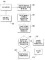
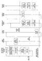
- FIG. 1is a flow chart illustrating operations of a pharmaceutical verification system according to embodiments of the present invention.
- FIG. 2is a front right perspective view of a pharmaceutical verification system according to embodiments of the present invention, with the side walls and end walls removed.
- FIG. 3is a front left perspective view of the pharmaceutical verification system of FIG. 2 .
- FIG. 4is a right front perspective view of the vial loading station and the bar code scanning station of the pharmaceutical verification system of FIG. 2 .
- FIG. 5is an enlarged rear perspective view of the bar code scanning station of FIG. 4 .
- FIG. 6is an enlarged side section view of the vision station of the pharmaceutical verification system of FIG. 2 showing a vial entering the vision chamber.
- FIG. 7is a top front perspective view of the wheel conveyor and the vision and spectroscopy stations of the pharmaceutical verification system of FIG. 2 with the housing removed.
- FIG. 8is a rear top perspective view of the wheel conveyor and the vision, spectroscopy, and stamping stations of the pharmaceutical verification system of FIG. 2 , with the housing and upper shelf removed.
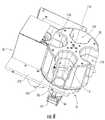
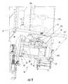
- FIG. 9is a bottom, left, front perspective view of the spectroscopy station of the pharmaceutical verification system of FIG. 2 , with the floor section in its level position.
- FIG. 10is a bottom, left, front perspective view of the spectroscopy station of the pharmaceutical verification system of FIG. 2 , with the floor section in its tilted position.
- FIG. 11is a top view of the vision, spectroscopy and stamping stations of the pharmaceutical verification system of FIG. 2 , showing a vial being stamped for approval.
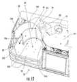
- FIG. 12is a top, left perspective view of the offload station of the pharmaceutical verification system of FIG. 2 , with the gate of the offload station shown in its closed position; the bar code scanning station and ceiling have been removed.
- FIG. 13is a top, rear, right perspective view of the offload station of FIG. 12 showing the gate in its open position.
- FIG. 14is a concurrency diagram illustrating the sequence and concurrency of operational steps according to embodiments of the invention.
- spatially relative termssuch as “under”, “below”, “lower”, “over”, “upper,” “front,” “rear” and the like, may be used herein for ease of description to describe one element or feature's relationship to another element(s) or feature(s) as illustrated in the figures. It will be understood that the spatially relative terms are intended to encompass different orientations of the device in use or operation in addition to the orientation depicted in the figures. For example, if the device in the figures is turned over, elements described as “under” or “beneath” other elements or features would then be oriented “over” the other elements or features. Thus, the exemplary term “under” can encompass both an orientation of over and under. The device may be otherwise oriented (rotated 90 degrees or at other orientations) and the spatially relative descriptors used herein interpreted accordingly.
- embodiments of the present inventionare directed to an automated system and/or method for verifying the identity of a dispensed pharmaceutical in a pharmaceutical vial ( FIG. 1 ).
- vialsare loaded into the system for verification (Block 1000 ).
- the bar code on the label of each vialis then scanned (Block 1002 ) to identify the drug called for by the prescription (hereinafter the “prescribed pharmaceutical”)(Block 1003 ).
- the vialis then scanned by a vision system for a comparison of the drug inside the vial (hereinafter the “dispensed pharmaceutical”) and an image or other visual representation of the drug identified by the bar code (Block 1004 ).
- the vialis then subjected to spectroscopic analysis, with the spectrum generated for the dispensed pharmaceutical being compared to a known spectrum for identification purposes (Block 1006 ). If the identities of the prescribed pharmaceutical and the dispensed pharmaceutical match (Block 1007 ), the vial is stamped as approved (Block 1008 ) and offloaded for subsequent pick-up (Block 1010 ). If the identities do not match, the vial is rejected (Block 1012 ).
- the system 20includes a vial loading station 21 , a bar code scanning station 22 , a vision station 24 , a spectroscopy station 26 , a stamping station 28 , and an offload station 30 . Vials are moved between these stations with a sliding conveyor 39 (FIGS. 4 and 5 ) and a wheel conveyor 32 ( FIGS. 7 and 8 ). A controller 200 controls the operation of the various stations, the sliding conveyor 39 and the wheel conveyor 32 . These components will be described in greater detail below.
- a housing 300which includes a floor 302 , a ceiling 304 , side walls 305 , 306 , and end walls 307 , 308 . These panels form a generally box-shaped housing. Shelves 310 , 312 , 314 are positioned between the floor 302 and the ceiling 304 and serve as mounting locations for some of the components of the various stations.
- the vial loading station 21is mounted on top of the ceiling 304 .
- the vial loading station 21includes a sloping ramp 34 on which are mounted a set of dividers 36 .
- the ramp 34is supported from underneath by a scaffold 33 and a wedge-shaped block 31 .
- the dividers 36define a series of parallel lanes 38 that terminate at a lower region of the ramp 34 .
- the dividers 36are sized and positioned to form lanes 38 of different heights and/or widths.
- a retractable stop 40extends into the lane 38 to prevent the undetained passage of vials.
- Each lane 38may also include a sensor (not shown) to detect the presence of a vial.
- An exit hole 35is located on the ramp below the ends of the lanes 38 ; a spring-loaded retractable cover 37 covers the exit hole 35 .
- the sliding conveyor 39is located and includes a semicylindrical holder 42 mounted on a slide frame 44 with its open side facing the lanes 38 .
- the slide frame 44is in turn mounted on a rail 46 that extends perpendicular to the direction of the lanes 38 .
- a drive mechanism 48is mounted to the slide frame 44 to drive the slide frame 44 and the holder 42 along the rail 46 .
- the bar code scanning station 22includes a bar code scanner 49 mounted adjacent to and beside an outermost divider 36 .
- the bar code scanner 49is oriented to scan a vial positioned within the holder 42 when the holder 42 is moved outside of the outermost divider 36 (i.e., near the side wall 305 ).
- a small turntable 47 driven by a motor and belt(not shown, and mounted under the ramp 34 ) is positioned between the bar code scanner 49 and the rail 46 .
- the lanes 38are loaded at their upper ends with labeled, filled, capped pharmaceutical vials.
- the vialsmay be loaded by hand, or may be loaded with a robotic arm, such as the carriers of the automated pharmaceutical dispensing machines discussed in U.S. patent application Ser. No. 11/599,526, filed Nov. 14, 2006, and U.S. patent application Ser. No. 12/014,285, filed Jan. 15, 2008, the disclosures of which are hereby incorporated herein.
- the controller 200determines from which lane 38 a loaded vial is to be released and actuates the drive mechanism 48 of the sliding conveyor 39 to slide the holder 42 into position at the end of the designated lane 38 .
- the controller 200then signals the stop 40 in that lane 38 to retract, thereby enabling the vial to slide down the ramp 34 and into the holder 42 .
- the controller 200signals the drive mechanism 48 of the sliding conveyor 39 to slide the holder 42 and vial to the far end of the rail 46 to a position upon the turntable 47 in front of the bar code scanner 49 .
- the controller 200signals the turntable motor to rotate the turntable 47 .
- the bar code scanner 49reads the bar code on the vial and stores information contained therein, including the identity of the prescribed pharmaceutical (or a pharmacy/prescription code that indirectly identifies the pharmaceutical), in memory accessible to the controller 200 .
- the turntable 47may also be omitted in some embodiments.
- the conveyor lanes 38are not required; in some embodiments a technician may commence operations by simply placing a vial in position for scanning.
- the conveyormay be configured as a belt conveyor, a robotic arm, or the like as desired.
- a suction tube-type delivery unitin which vials are conveyed to and from the system 20 via tubes to which suction is applied, may be employed in place of or in conjunction with the loading station 21 and/or the offloading station 30 .
- the controller 200signals the drive mechanism 48 of the sliding conveyor 39 to slide the holder 42 and vial along the rail 46 to the exit hole 35 .
- the cover 37is configured such that a vial sliding away from the bar code scanner 49 forces the cover 37 away from the exit hole 35 (for example, the cover 37 may be spring-loaded toward its closed position, with a stepped ramp that catches on the bottom edge of a vial traveling away from the bar code scanner 49 ).
- the vialdrops through the exit hole 35 , through a tube 50 positioned between the ramp 34 and the ceiling 304 , and into a recess 110 of the wheel conveyer 32 as the recess 110 is positioned in the vision station 24 ( FIG. 6 ).
- the wheel conveyor 32is generally a round wheel or carousel with four substantially identical open-sided recesses 110 located approximately 90 degrees apart. Each of the recesses 110 is flared outwardly at its top edges to encourage dropping vials to descend to the bottom of the recess 110 and is open at its bottom end.
- the wheel conveyor 32is rotatably mounted on the shelf 312 for rotation about an axis A 1 .
- a motor(not shown) is attached to the wheel conveyor 32 and mounted under the shelf 312 and is configured to drive the wheel conveyor 32 about the axis A 1 according to signals from the controller 200 .
- the illustrated wheel conveyor 32has four recesses 110 , but other numbers of recesses may be suitable. Also, other types of conveyors, such as belt conveyors and robotic arms, may be employed to move the vial between stations.
- the recess 110 , the shelf 312 and the shelf 314combine to form a chamber 51 of the vision station 24 .
- the shelf 312includes a window 311 (typically covered with glass, which may be tinted) that provides visual access to the chamber 51 from underneath.
- a camera 52is mounted on the shelf 310 and positioned to acquire an image through the window 311 .
- a light dome 53is positioned between the camera 52 and the window 311 .
- a light ring 54is mounted to the lower rim of the light dome 53 to provide light to the chamber 51 .
- the light ring 54includes adjustable RGB lighting capability, such that the color of light emitted by the light ring 54 can be adjusted as desired. Additional detail regarding the vision station is set forth in co-pending and co-assigned U.S. Provisional Patent Application Ser. No. 61/118,014, filed Nov. 26, 2008, and U.S. patent application Ser. No. 12/623,878, filed concurrently and entitled System and Method for Acquiring Images, the disclosure of each of which is hereby incorporated herein in its entirety.
- a vialdrops into the chamber 51 through the exit hole 35 , the tube 50 , and through holes 55 , 56 in the ceiling 304 and shelf 314 , respectively.
- the shape of the recess 110urges the vial to the bottom of the chamber 51 (formed by the shelf 312 and the window 311 ), where it rests with its bottom end on the window 311 .
- the controller 200activates the camera 52 to acquire one or more images of the pharmaceuticals in the vial, typically while illuminated by the light ring 54 .
- the chamber 51 or the vialmay be illuminated with a colored light that is substantially the “inverse” of the color of the vial, as such illumination may improve the quality of the image of the pharmaceuticals; this technique is discussed in co-pending and co-assigned U.S. patent application Ser. No. 12/249,402, filed Oct. 10, 2008, the disclosure of which is hereby incorporated herein in its entirety.
- the images taken by the camera 52can then be stored in memory accessible by the controller 200 and/or compared to stored images of the prescribed pharmaceutical to assist in the verification process.
- the vision station 24is designed to attempt to control, preferably to reduce or minimize, the amount of external or ambient light reaching the chamber 51 in order to improve the quality and consistency of images acquired therein.
- the vision stationmay use white light and/or may use direct or indirect light to illuminate the vial.
- the vision stationmay also use infrared light for illumination and/or may be designed to illuminate the vial from other angles.
- video or still imagesmay be acquired.
- the vision stationmay include features that maintain the vial above the window 311 in order to avoid scratching the glass, and/or the vision station may be modified such that the vial does not drop directly onto the window 311 .
- the controller 200signals the wheel conveyor motor to rotate the wheel conveyor 32 90 degrees (this rotation is clockwise from the vantage point of FIG. 7 ), which slides the vial on the shelf 312 and positions the vial in the spectroscopy station 26 .
- the spectroscopy station 26includes a pivoting floor section 60 that includes an open window (not shown).
- the floor section 60is attached to the shelf 312 at a pivot 67 located near the axis A 1 .
- Two rollers 64 a , 64 bare mounted on the floor section 60 for rotation about axes of rotation that are generally normal to the floor section 60 , and driven by a drive motor 65 via a belt pulley 65 a and a belt 65 b that are mounted to the underside of the floor section 60 .
- a tilt mechanism 62is attached to the shelf 312 to move the floor section 60 to move it between a level position, in which the floor section 60 is substantially coplanar with the shelf 312 ( FIG. 9 ), and a tilted position, in which the floor section 60 rotates about the pivot 67 to lowers its opposite edge ( FIG. 10 ).
- the tilt mechanism 62includes a vertical guide shaft 68 that extends between the shelves 310 , 312 , an acme screw 69 that also extends between the shelves 310 , 312 , and a supporting follower 70 that is threaded onto the acme screw 69 .
- the supporting follower 70supports the floor section 60 from underneath.
- a motor 73 mounted on the upper surface of the shelf 312drives the acme screw 69 .
- the spectroscopy station 26includes a spectroscopic probe 66 that is positioned below the shelf 312 .
- An exemplary configuration for the spectrometer and probe 66is described in U.S. patent application Ser. No. 11/972,849, supra.
- the spectroscopic probe 66is oriented to shine a laser beam through the window (not shown) in the floor section 60 when the floor section 60 is in its tilted position.
- the controller 200signals the tilt mechanism 62 to lower the floor section 60 from the level position to the tilted position. To do so, the acme screw motor 73 rotates the acme screw 69 so that the supporting follower 70 descends. The floor section 60 descends with the supporting follower 70 as it pivots about the pivot 67 . In the tilted position ( FIG. 10 ), the vial rests against the rollers 64 a , 64 b . The controller 200 then signals the spectroscopic probe 66 to acquire one or more spectra of the pharmaceuticals in the vial.
- the motor 65drives the belt pulley 65 a , which in turn drives the belt 65 b . Movement of the belt 65 b rotates the rollers 64 a , 64 b , which in turn rotates the vial. Such rotation can assist the pills in “settling” in the vial and provide multiple “views” of the vial to the spectroscopic probe 66 , which can enable the controller 200 to select the view that provides the more accurate reading(s) and/or can reduce the heating effect of the spectroscopic laser on the sample and the vial.
- the spectral datacan then be stored in memory accessible to the controller 200 and/or compared to stored spectral data to determine whether the dispensed pharmaceutical matches the prescribed pharmaceutical. It should be noted that the spectroscopic station 26 is designed to attempt to control, preferably to reduce or minimize, the amount of external or ambient light reaching the vial in order to improve the quality and consistency of spectral data acquired therein.
- the spectroscopeis a Raman spectrometer; in other embodiments, other spectroscopic techniques, such as IR, near-IR, or ultraviolet, may be employed.
- the spectroscopy stationmay employ a non-pivoting floor, a non-tilting floor and/or rollers to rotate the vial, or may have other mechanisms to tilt and/or rotate the vial.
- the controller 200signals the tilt mechanism 62 to raise the floor section 60 back to the level position ( FIG. 9 ). The controller 200 then signals the motor (not shown) to rotate the wheel conveyor 32 90 degrees to move the vial to the stamping station 28 ( FIG. 11 ). If the procedures followed in the vision and spectroscopy stations 24 , 26 indicate that the dispensed pharmaceutical matches the prescribed pharmaceutical, the controller 200 then signals a stamping device 82 in the stamping station 28 mounted under the shelf 312 to mark the vial (typically on the bottom of the vial) with indicia of verification.
- the controller 200does not signal the stamping device 82 to mark the vial (similarly, the stamping device 82 does not mark the vial if approval is withheld for another reason, such as the prescribed pharmaceutical not being included in the memory of the controller 200 , thereby precluding analysis of the prescription).
- Procedures for determining whether the identities of the dispensed and prescribed pharmaceuticals matchare described in co-pending and co-assigned U.S. Provisional Patent Application Ser. No. 61/118,011, filed Nov. 26, 2009, and, U.S. patent application Ser. No. 12/623,822, filed concurrently, the disclosure of each of which is hereby incorporated herein by reference in its entirety.
- a UV-sensitive dye or the likemay be used to stamp the vial to avoid copying.
- a UV-sensitive ink or the likemay be employed to avoid interference with other information on the label.
- Those skilled in this artwill appreciate that other means of approving the vial, such as printing on the label or the vial, lasing a mark on the vial, or writing to an RFID tag, may also be employed at an approval station, or the approval station may be omitted entirely in some embodiments.
- the controller 200signals the wheel conveyor motor to rotate the wheel conveyor 32 another 90 degrees to the offload station 30 ( FIGS. 12 and 13 ).
- the offload station 30includes a turntable 90 that is mounted within an opening in a platform 320 that is generally coplanar with the shelf 312 ; the turntable 90 is mounted to rotate about an axis of rotation A 3 .
- One section of the turntable 90underlies the recess 110 of the wheel conveyor 32 as that recess 110 is positioned in an offloading position (i.e., 90 degrees from each of the vision and stamping stations 24 , 28 ).
- a motoris mounted under the platform 320 to drive the turntable 90 about the axis A 3 .
- An outer guide 92is mounted on the platform 320 over a portion of the perimeter of the turntable 90 between the offload position and the vision station 24 .
- a gap 93 between the outer guide 92 and outer wall 100leads to an exception area 98 .
- An inner wall 94is mounted to the platform 320 such that a travel path segment P 1 is formed on the turntable 90 between the inner wall 94 and the outer guide 92 .
- the inner wall 94has a generally semicircular portion 94 a and a separate arcuate portion 94 b .
- the outer wall 100is mounted to the platform 320 over approximately 70 degrees of the perimeter of the turntable 90 .
- a travel path segment P 2is defined between the outer wall 100 and much of the semicircular portion of the inner wall 94 , such that together the segments P 1 , P 2 form a travel path P 3 .
- a gate 96is pivotally attached at a pivot 104 to the end of the outer wall 100 nearest the outer guide.
- the interior of the semicircular portion 94 aforms a collection area 102 that is generally concentric with the turntable 90 .
- the gate 96begins in a closed position ( FIG. 12 ), in which it separates the path segments P 1 , P 2 of the travel path P 3 and leaves open the gap 93 between the outer guide 92 and outer wall 100 . If the operations performed by the vision station 24 and/or the spectroscopic station 26 determine that verification of the dispensed pharmaceutical as the prescribed pharmaceutical cannot be achieved, the controller 200 instructs the gate 96 to remain in the closed position. As the wheel conveyor 32 rotates the vial to a position over a segment of the turntable 90 , it deposits the vial along the path segment P 1 onto the turntable 90 . Rotation of the turntable 90 (counterclockwise from the vantage point of FIG. 12 ) then conveys the vial to and through the gap 93 and into the exception area 98 , where it can be removed by a technician.
- the controller 200instructs the gate 96 to move to an open position ( FIG. 13 ), in which the gate 96 covers the gap 93 .
- the vialcan then follow path segments P 1 and P 2 between the inner and outer walls 94 , 100 .
- Continued rotationconveys the vial to the surface of the arcuate portion 94 b of the inner wall 94 opposite the wheel conveyor 32 , then to the pocket 102 .
- the verified vialcan then be retrieved from the pocket 102 .
- offloading vialsmay be suitable for use with the present invention.
- some offload stationsmay not physically separate approved and exception vials, but instead may rely on visual indicia on the vial to notify a technician of exceptions.
- Some embodimentsmay employ lanes, chutes or suction tubes rather than a turntable to separate exceptions and/or to offload vials.
- Other configurationswill be apparent to those of skill in this art.
- the vision, spectroscopy and stamping stations 24 , 26 , 28are idle as the sliding conveyor 39 moves the vial from the vial loading station 21 to a position in front of the bar code scanner 49 .
- the wheel conveyor 32rotates 90 degrees.
- the sliding conveyor 39moves the vial to the opening 35 , moving the door 37 to an open position while doing so.
- the floor section 61 of the spectroscopy station 26is lowered, the stamping device 82 stamps a vial in the stamping station 28 , and the turntable 90 is activated and begins to rotate.
- the spectroscopic probe 66acquires a spectrum of a vial, and the gate 93 moves to its open or closed position (if necessary).
- an imageis taken in the vision station 24 , the floor section 61 is raised to its level position, and the turntable 90 ceases its rotation.
- the imaging, spectroscopy, and stamping stepsare complete, and a previously stamped vial has been offloaded.
- the processis then repeated when another vial is scanned in the bar code scanning station 22 .
- Software for the controller 200that enables it to control operation of the system 20 is described in co-pending and co-assigned U.S. Provisional Patent Application No. 61/118,011 and U.S. patent application Ser. No. 12/623,822, supra
Landscapes
- Physics & Mathematics (AREA)
- Health & Medical Sciences (AREA)
- General Health & Medical Sciences (AREA)
- General Physics & Mathematics (AREA)
- Spectroscopy & Molecular Physics (AREA)
- Life Sciences & Earth Sciences (AREA)
- Chemical & Material Sciences (AREA)
- Analytical Chemistry (AREA)
- Biochemistry (AREA)
- Immunology (AREA)
- Pathology (AREA)
- Medical Preparation Storing Or Oral Administration Devices (AREA)
- Automatic Analysis And Handling Materials Therefor (AREA)
- Business, Economics & Management (AREA)
- Tourism & Hospitality (AREA)
- Child & Adolescent Psychology (AREA)
- Economics (AREA)
- Human Resources & Organizations (AREA)
- Marketing (AREA)
- Primary Health Care (AREA)
- Strategic Management (AREA)
- General Business, Economics & Management (AREA)
- Engineering & Computer Science (AREA)
- Theoretical Computer Science (AREA)
Abstract
Description
Claims (5)
Priority Applications (3)
| Application Number | Priority Date | Filing Date | Title |
|---|---|---|---|
| US12/623,917US8284386B2 (en) | 2008-11-26 | 2009-11-23 | System and method for verifying the contents of a filled, capped pharmaceutical prescription |
| PCT/US2009/065608WO2010062869A1 (en) | 2008-11-26 | 2009-11-24 | System and method for verifying the contents of a filled, capped pharmaceutical prescription |
| US13/611,800US8908163B2 (en) | 2008-11-26 | 2012-09-12 | System and method for verifying the contents of a filled, capped pharmaceutical prescription |
Applications Claiming Priority (2)
| Application Number | Priority Date | Filing Date | Title |
|---|---|---|---|
| US11800608P | 2008-11-26 | 2008-11-26 | |
| US12/623,917US8284386B2 (en) | 2008-11-26 | 2009-11-23 | System and method for verifying the contents of a filled, capped pharmaceutical prescription |
Related Child Applications (1)
| Application Number | Title | Priority Date | Filing Date |
|---|---|---|---|
| US13/611,800DivisionUS8908163B2 (en) | 2008-11-26 | 2012-09-12 | System and method for verifying the contents of a filled, capped pharmaceutical prescription |
Publications (2)
| Publication Number | Publication Date |
|---|---|
| US20100131097A1 US20100131097A1 (en) | 2010-05-27 |
| US8284386B2true US8284386B2 (en) | 2012-10-09 |
Family
ID=42197032
Family Applications (2)
| Application Number | Title | Priority Date | Filing Date |
|---|---|---|---|
| US12/623,917Active2031-03-23US8284386B2 (en) | 2008-11-26 | 2009-11-23 | System and method for verifying the contents of a filled, capped pharmaceutical prescription |
| US13/611,800Expired - Fee RelatedUS8908163B2 (en) | 2008-11-26 | 2012-09-12 | System and method for verifying the contents of a filled, capped pharmaceutical prescription |
Family Applications After (1)
| Application Number | Title | Priority Date | Filing Date |
|---|---|---|---|
| US13/611,800Expired - Fee RelatedUS8908163B2 (en) | 2008-11-26 | 2012-09-12 | System and method for verifying the contents of a filled, capped pharmaceutical prescription |
Country Status (2)
| Country | Link |
|---|---|
| US (2) | US8284386B2 (en) |
| WO (1) | WO2010062869A1 (en) |
Cited By (5)
| Publication number | Priority date | Publication date | Assignee | Title |
|---|---|---|---|---|
| US20130238120A1 (en)* | 2009-09-30 | 2013-09-12 | Carefusion 303, Inc. | Verification of dispensed items |
| US20140114470A1 (en)* | 2012-10-24 | 2014-04-24 | Rashid Pharmacy, P.L.C. | Methods and systems for improving efficiency of pharmacy practice and reducing the incidence of medication errors |
| US10073954B2 (en) | 2016-08-26 | 2018-09-11 | Changhai Chen | Dispenser system and methods for medication compliance |
| US10722431B2 (en) | 2016-08-26 | 2020-07-28 | Changhai Chen | Dispenser system and methods for medication compliance |
| US11246805B2 (en) | 2016-08-26 | 2022-02-15 | Changhai Chen | Dispenser system and methods for medication compliance |
Families Citing this family (16)
| Publication number | Priority date | Publication date | Assignee | Title |
|---|---|---|---|---|
| US8462206B1 (en)* | 2010-02-25 | 2013-06-11 | Amazon Technologies, Inc. | Image acquisition system |
| US9930297B2 (en) | 2010-04-30 | 2018-03-27 | Becton, Dickinson And Company | System and method for acquiring images of medication preparations |
| CN103250176A (en)* | 2010-08-13 | 2013-08-14 | 智能医学公司 | Systems and methods for producing individually tailored pharmaceutical products |
| EP2748685A4 (en) | 2011-08-27 | 2015-05-20 | Daniel L Kraft | PORTABLE DRUG DISPENSER |
| US9665689B2 (en)* | 2013-05-17 | 2017-05-30 | Viavi Solutions Inc. | Medication assurance system and method |
| GB2529724A (en)* | 2014-09-01 | 2016-03-02 | Promtek Ltd | Verification of material |
| DK3191809T3 (en) | 2014-09-08 | 2021-09-13 | Becton Dickinson Co | SYSTEM AND METHOD FOR MAKING A PHARMACEUTICAL COMPOUND |
| NL2017148B1 (en)* | 2016-07-11 | 2018-01-17 | Global Factories Total Engineering And Mfg B V | A method of evaluating individualized compounds of medicines, a control device, a packaging device and a computer program product |
| US9958324B1 (en)* | 2017-02-15 | 2018-05-01 | MarqMetrix Inc. | Enclosed benchtop raman spectrometry device |
| US10596319B2 (en) | 2017-11-23 | 2020-03-24 | Aesynt Incorporated | Compounding device system |
| US10991264B2 (en)* | 2017-11-23 | 2021-04-27 | Omnicell, Inc. | Multi-camera imaging for IV compounding |
| US11335444B2 (en) | 2017-11-30 | 2022-05-17 | Omnicell, Inc. | IV compounding systems and methods |
| US10872688B2 (en)* | 2018-07-30 | 2020-12-22 | Arxium, Inc. | Visual analysis pill dispenser |
| US10593425B1 (en) | 2018-11-19 | 2020-03-17 | Accenture Global Solutions Limited | Identification and verification of medication |
| US11966824B2 (en) | 2018-11-19 | 2024-04-23 | Accenture Global Solutions Limited | Identification and verification of medication |
| CN116159777B (en)* | 2023-04-18 | 2023-06-23 | 石家庄康力药业有限公司 | Quality judgment system and method based on visual detection |
Citations (52)
| Publication number | Priority date | Publication date | Assignee | Title |
|---|---|---|---|---|
| DE1117046B (en) | 1958-08-06 | 1961-11-09 | Heinrich Schaefer Dipl Ing | Distribution device for bottles with a rotating baffle plate |
| DE1180317B (en) | 1963-08-28 | 1964-10-22 | Pohlig Heckel Bleichert | Feeding and dividing device for bulk goods |
| US4223751A (en) | 1979-03-26 | 1980-09-23 | Modern Controls, Inc. | High speed capacitance apparatus for classifying pharmaceutical capsules |
| US4695163A (en) | 1985-06-17 | 1987-09-22 | Schachar Ronald A | Method and apparatus for determining surface shapes using reflected laser light |
| JPH03214045A (en) | 1990-01-18 | 1991-09-19 | Fujisawa Pharmaceut Co Ltd | Visual inspecting apparatus for vial |
| EP0452905A1 (en) | 1990-04-18 | 1991-10-23 | Hitachi, Ltd. | Method and apparatus for inspecting surface pattern of object |
| US5337902A (en) | 1993-08-13 | 1994-08-16 | Modern Controls, Inc. | Tablet sensor |
| US5337919A (en) | 1993-02-11 | 1994-08-16 | Dispensing Technologies, Inc. | Automatic dispensing system for prescriptions and the like |
| EP0656200A2 (en) | 1993-12-03 | 1995-06-07 | Owen Healthcare, Inc. | Apparatus for dispensing medication |
| US5504332A (en) | 1994-08-26 | 1996-04-02 | Merck & Co., Inc. | Method and system for determining the homogeneity of tablets |
| FR2726651A1 (en) | 1994-11-08 | 1996-05-10 | Bertin & Cie | Foreign bodies detection e.g. glass splinters in transparent liq. container, such as bottles |
| DE19501650A1 (en) | 1995-01-20 | 1996-07-25 | Altratec Montagesysteme | Transfer device for objects on transporters, such as conveyor belts |
| US5597995A (en) | 1995-11-08 | 1997-01-28 | Automated Prescription Systems, Inc. | Automated medical prescription fulfillment system having work stations for imaging, filling, and checking the dispensed drug product |
| US5679954A (en) | 1994-11-14 | 1997-10-21 | Soloman; Sabrie | Non-destructive identification of tablet and tablet dissolution by means of infared spectroscopy |
| US5768327A (en) | 1996-06-13 | 1998-06-16 | Kirby Lester, Inc. | Method and apparatus for optically counting discrete objects |
| US5770864A (en)* | 1996-12-31 | 1998-06-23 | Pitney Bowes Inc. | Apparatus and method for dimensional weighing utilizing a laser scanner or sensor |
| US5826696A (en) | 1994-08-11 | 1998-10-27 | Walter Grassle Gmbh | Apparatus for separating small articles |
| US5884806A (en) | 1996-12-02 | 1999-03-23 | Innovation Associates, Inc. | Device that counts and dispenses pills |
| US5907493A (en) | 1997-01-31 | 1999-05-25 | Innovation Associates, Inc. | Pharmaceutical dispensing system |
| US5960098A (en) | 1995-06-07 | 1999-09-28 | Agri-Tech, Inc. | Defective object inspection and removal systems and methods for identifying and removing defective objects |
| WO1999061324A2 (en) | 1998-05-27 | 1999-12-02 | Nextrx Corporation | Automated pharmaceutical management and dispensing system |
| US6364517B1 (en) | 1997-02-26 | 2002-04-02 | Kabushiki Kaisha Yuyama Seisakusho | Drug dispenser and quantity input device |
| US6363687B1 (en) | 2000-03-06 | 2002-04-02 | Luciano Packaging Technologies, Inc. | Secured cell, rapid fill automated tablet order filling system |
| WO2002069897A2 (en) | 2001-03-02 | 2002-09-12 | Euro-Celtique, S.A. | Method and apparatus for compounding individualized dosage forms |
| US6471088B1 (en) | 1998-09-29 | 2002-10-29 | Sanyo Electric Co., Ltd. | Medicine supply apparatus |
| US6497342B2 (en) | 2000-11-30 | 2002-12-24 | Mckesson Automated Healthcare, Inc. | Medicine feeder |
| US6509537B1 (en) | 1999-05-14 | 2003-01-21 | Gunther Krieg | Method and device for detecting and differentiating between contaminations and accepts as well as between different colors in solid particles |
| US6522945B2 (en)* | 1996-09-06 | 2003-02-18 | Merck & Company, Inc. | Customer specific packaging line |
| US6535637B1 (en) | 1997-04-04 | 2003-03-18 | Esco Electronics, Inc. | Pharmaceutical pill recognition and verification system |
| US6607094B2 (en) | 2001-08-03 | 2003-08-19 | Macdonald Nathan Hollis | Apparatus and method for dispensing medication |
| US20040004085A1 (en) | 2002-05-14 | 2004-01-08 | Williams Jeffrey P. | System and method for dispensing prescriptions |
| US6690464B1 (en) | 1999-02-19 | 2004-02-10 | Spectral Dimensions, Inc. | High-volume on-line spectroscopic composition testing of manufactured pharmaceutical dosage units |
| US20040104241A1 (en) | 2002-07-29 | 2004-06-03 | Brian Broussard | Article dispensing and counting method and device |
| US20040133705A1 (en) | 2002-08-09 | 2004-07-08 | Brian Broussard | Controller for dispensing products |
| US6771369B2 (en) | 2002-03-12 | 2004-08-03 | Analytical Spectral Devices, Inc. | System and method for pharmacy validation and inspection |
| JP2004226071A (en) | 2003-01-20 | 2004-08-12 | Hitachi Industries Co Ltd | Foreign object detection method and device |
| WO2004072868A1 (en) | 2003-02-10 | 2004-08-26 | Verication, L.L.C. | Database and method of use for authenticity verification of pharmaceuticals |
| US20050004495A1 (en) | 2003-07-03 | 2005-01-06 | Ambarish Goswami | Kinematic quantification of gait asymmetry based on bilateral cyclograms |
| WO2005031302A2 (en) | 2003-09-22 | 2005-04-07 | University Of Maryland, Baltimore | Drug authentication |
| US6919556B1 (en) | 2002-02-22 | 2005-07-19 | Monocle Technologies, Inc. | System and method for monitoring and evaluating solid and semi-solid materials |
| US20050288906A1 (en) | 2004-06-29 | 2005-12-29 | Drennen James K Iii | Spectroscopic pharmacy verification and inspection system |
| US20060041330A1 (en) | 2004-08-18 | 2006-02-23 | Walgreen Co. | System and method for checking the accuracy of a prescription fill |
| US7028723B1 (en) | 2003-11-03 | 2006-04-18 | Alouani Ali Tahar | Apparatus and method for automatic prescription verification |
| US7080755B2 (en) | 2004-09-13 | 2006-07-25 | Michael Handfield | Smart tray for dispensing medicaments |
| US7099741B2 (en) | 2002-06-24 | 2006-08-29 | Campbell Soup Company | Control systems and methods of dispensing items |
| US20070008523A1 (en) | 2003-04-16 | 2007-01-11 | Kaye Stephen T | Rapid pharmaceutical identification and verification system |
| US20070042346A1 (en) | 2004-11-24 | 2007-02-22 | Battelle Memorial Institute | Method and apparatus for detection of rare cells |
| US20070093932A1 (en) | 2002-05-14 | 2007-04-26 | Antioch Holdings, Inc. | Automatically programmable dispensing apparatus and method |
| US20070150092A1 (en) | 2004-01-05 | 2007-06-28 | Tosho Inc. | Automatic dispensation device and medicine |
| US20080061074A1 (en) | 2004-03-15 | 2008-03-13 | Parata Systems, L.L.C. | Vacuum Based Pill Singulator and Counter Based Thereon |
| WO2008088729A1 (en) | 2007-01-12 | 2008-07-24 | Parata Systems, Llc | System and method for verifying the contents of a filled, capped pharmaceutical prescription |
| USRE40453E1 (en) | 1994-05-27 | 2008-08-12 | Medco Health Solutions, Inc. | Enhanced drug dispensing system |
Family Cites Families (3)
| Publication number | Priority date | Publication date | Assignee | Title |
|---|---|---|---|---|
| US4847474A (en)* | 1988-01-12 | 1989-07-11 | Hewlett-Packard Company | Method and apparatus for reading a bar code |
| KR100704324B1 (en)* | 1998-05-01 | 2007-04-09 | 젠-프로브 인코포레이티드 | Automated Analytical Instruments and Automated Analytical Methods |
| US6887656B2 (en) | 2003-01-17 | 2005-05-03 | Eastman Kodak Company | Color photographic element containing improved heterocyclic speed enhancing compound |
- 2009
- 2009-11-23USUS12/623,917patent/US8284386B2/enactiveActive
- 2009-11-24WOPCT/US2009/065608patent/WO2010062869A1/enactiveApplication Filing
- 2012
- 2012-09-12USUS13/611,800patent/US8908163B2/ennot_activeExpired - Fee Related
Patent Citations (57)
| Publication number | Priority date | Publication date | Assignee | Title |
|---|---|---|---|---|
| DE1117046B (en) | 1958-08-06 | 1961-11-09 | Heinrich Schaefer Dipl Ing | Distribution device for bottles with a rotating baffle plate |
| DE1180317B (en) | 1963-08-28 | 1964-10-22 | Pohlig Heckel Bleichert | Feeding and dividing device for bulk goods |
| US4223751A (en) | 1979-03-26 | 1980-09-23 | Modern Controls, Inc. | High speed capacitance apparatus for classifying pharmaceutical capsules |
| US4695163A (en) | 1985-06-17 | 1987-09-22 | Schachar Ronald A | Method and apparatus for determining surface shapes using reflected laser light |
| JPH03214045A (en) | 1990-01-18 | 1991-09-19 | Fujisawa Pharmaceut Co Ltd | Visual inspecting apparatus for vial |
| EP0452905A1 (en) | 1990-04-18 | 1991-10-23 | Hitachi, Ltd. | Method and apparatus for inspecting surface pattern of object |
| US5337919A (en) | 1993-02-11 | 1994-08-16 | Dispensing Technologies, Inc. | Automatic dispensing system for prescriptions and the like |
| US5337902A (en) | 1993-08-13 | 1994-08-16 | Modern Controls, Inc. | Tablet sensor |
| EP0656200A2 (en) | 1993-12-03 | 1995-06-07 | Owen Healthcare, Inc. | Apparatus for dispensing medication |
| USRE40453E1 (en) | 1994-05-27 | 2008-08-12 | Medco Health Solutions, Inc. | Enhanced drug dispensing system |
| US5826696A (en) | 1994-08-11 | 1998-10-27 | Walter Grassle Gmbh | Apparatus for separating small articles |
| US5504332A (en) | 1994-08-26 | 1996-04-02 | Merck & Co., Inc. | Method and system for determining the homogeneity of tablets |
| FR2726651A1 (en) | 1994-11-08 | 1996-05-10 | Bertin & Cie | Foreign bodies detection e.g. glass splinters in transparent liq. container, such as bottles |
| US5679954A (en) | 1994-11-14 | 1997-10-21 | Soloman; Sabrie | Non-destructive identification of tablet and tablet dissolution by means of infared spectroscopy |
| DE19501650A1 (en) | 1995-01-20 | 1996-07-25 | Altratec Montagesysteme | Transfer device for objects on transporters, such as conveyor belts |
| US5960098A (en) | 1995-06-07 | 1999-09-28 | Agri-Tech, Inc. | Defective object inspection and removal systems and methods for identifying and removing defective objects |
| US5597995A (en) | 1995-11-08 | 1997-01-28 | Automated Prescription Systems, Inc. | Automated medical prescription fulfillment system having work stations for imaging, filling, and checking the dispensed drug product |
| US5768327A (en) | 1996-06-13 | 1998-06-16 | Kirby Lester, Inc. | Method and apparatus for optically counting discrete objects |
| US20030176942A1 (en) | 1996-09-06 | 2003-09-18 | Merck & Co., Inc. | Customer specific packaging line |
| US6522945B2 (en)* | 1996-09-06 | 2003-02-18 | Merck & Company, Inc. | Customer specific packaging line |
| US5884806A (en) | 1996-12-02 | 1999-03-23 | Innovation Associates, Inc. | Device that counts and dispenses pills |
| US5770864A (en)* | 1996-12-31 | 1998-06-23 | Pitney Bowes Inc. | Apparatus and method for dimensional weighing utilizing a laser scanner or sensor |
| US5907493A (en) | 1997-01-31 | 1999-05-25 | Innovation Associates, Inc. | Pharmaceutical dispensing system |
| US6364517B1 (en) | 1997-02-26 | 2002-04-02 | Kabushiki Kaisha Yuyama Seisakusho | Drug dispenser and quantity input device |
| US6535637B1 (en) | 1997-04-04 | 2003-03-18 | Esco Electronics, Inc. | Pharmaceutical pill recognition and verification system |
| WO1999061324A2 (en) | 1998-05-27 | 1999-12-02 | Nextrx Corporation | Automated pharmaceutical management and dispensing system |
| US6471088B1 (en) | 1998-09-29 | 2002-10-29 | Sanyo Electric Co., Ltd. | Medicine supply apparatus |
| US6690464B1 (en) | 1999-02-19 | 2004-02-10 | Spectral Dimensions, Inc. | High-volume on-line spectroscopic composition testing of manufactured pharmaceutical dosage units |
| US6509537B1 (en) | 1999-05-14 | 2003-01-21 | Gunther Krieg | Method and device for detecting and differentiating between contaminations and accepts as well as between different colors in solid particles |
| US6363687B1 (en) | 2000-03-06 | 2002-04-02 | Luciano Packaging Technologies, Inc. | Secured cell, rapid fill automated tablet order filling system |
| US6497342B2 (en) | 2000-11-30 | 2002-12-24 | Mckesson Automated Healthcare, Inc. | Medicine feeder |
| WO2002069897A2 (en) | 2001-03-02 | 2002-09-12 | Euro-Celtique, S.A. | Method and apparatus for compounding individualized dosage forms |
| US6607094B2 (en) | 2001-08-03 | 2003-08-19 | Macdonald Nathan Hollis | Apparatus and method for dispensing medication |
| US6919556B1 (en) | 2002-02-22 | 2005-07-19 | Monocle Technologies, Inc. | System and method for monitoring and evaluating solid and semi-solid materials |
| US6771369B2 (en) | 2002-03-12 | 2004-08-03 | Analytical Spectral Devices, Inc. | System and method for pharmacy validation and inspection |
| US20040207842A1 (en) | 2002-03-12 | 2004-10-21 | Rzasa David M. | System and method for pharmacy validation and inspection |
| US7006214B2 (en) | 2002-03-12 | 2006-02-28 | Analytical Spectral Devices, Inc. | System and method for pharmacy validation and inspection |
| US20040004085A1 (en) | 2002-05-14 | 2004-01-08 | Williams Jeffrey P. | System and method for dispensing prescriptions |
| US20070093932A1 (en) | 2002-05-14 | 2007-04-26 | Antioch Holdings, Inc. | Automatically programmable dispensing apparatus and method |
| US7099741B2 (en) | 2002-06-24 | 2006-08-29 | Campbell Soup Company | Control systems and methods of dispensing items |
| US20040104241A1 (en) | 2002-07-29 | 2004-06-03 | Brian Broussard | Article dispensing and counting method and device |
| US7139639B2 (en) | 2002-07-29 | 2006-11-21 | Mckesson Automation Systems Inc. | Article dispensing and counting method and device |
| US20040133705A1 (en) | 2002-08-09 | 2004-07-08 | Brian Broussard | Controller for dispensing products |
| JP2004226071A (en) | 2003-01-20 | 2004-08-12 | Hitachi Industries Co Ltd | Foreign object detection method and device |
| WO2004072868A1 (en) | 2003-02-10 | 2004-08-26 | Verication, L.L.C. | Database and method of use for authenticity verification of pharmaceuticals |
| US20070008523A1 (en) | 2003-04-16 | 2007-01-11 | Kaye Stephen T | Rapid pharmaceutical identification and verification system |
| US7218395B2 (en) | 2003-04-16 | 2007-05-15 | Optopo Inc. | Rapid pharmaceutical identification and verification system |
| US20050004495A1 (en) | 2003-07-03 | 2005-01-06 | Ambarish Goswami | Kinematic quantification of gait asymmetry based on bilateral cyclograms |
| WO2005031302A2 (en) | 2003-09-22 | 2005-04-07 | University Of Maryland, Baltimore | Drug authentication |
| US7028723B1 (en) | 2003-11-03 | 2006-04-18 | Alouani Ali Tahar | Apparatus and method for automatic prescription verification |
| US20070150092A1 (en) | 2004-01-05 | 2007-06-28 | Tosho Inc. | Automatic dispensation device and medicine |
| US20080061074A1 (en) | 2004-03-15 | 2008-03-13 | Parata Systems, L.L.C. | Vacuum Based Pill Singulator and Counter Based Thereon |
| US20050288906A1 (en) | 2004-06-29 | 2005-12-29 | Drennen James K Iii | Spectroscopic pharmacy verification and inspection system |
| US20060041330A1 (en) | 2004-08-18 | 2006-02-23 | Walgreen Co. | System and method for checking the accuracy of a prescription fill |
| US7080755B2 (en) | 2004-09-13 | 2006-07-25 | Michael Handfield | Smart tray for dispensing medicaments |
| US20070042346A1 (en) | 2004-11-24 | 2007-02-22 | Battelle Memorial Institute | Method and apparatus for detection of rare cells |
| WO2008088729A1 (en) | 2007-01-12 | 2008-07-24 | Parata Systems, Llc | System and method for verifying the contents of a filled, capped pharmaceutical prescription |
Non-Patent Citations (34)
| Title |
|---|
| Aldridge et al., Identification of Tablet Formulations Inside Blister Packages by Near-Infrared Spectroscopy, 1994, vol. 48, No. 10, pp. 1272-1276, Applied Spectroscopy. |
| Alexander et al., New Technologies Forum 4: Process Measurement and Control, Date Unknown, pp. 1-18, royal Pharmaceutical Society. |
| Analyst, Application of Near-Infrared Reflectance Spectrometry to the Analytical Control of Pharmaceuticals: ranitidine Hydrochloride tablet Production, Feb. 1996, vol. 121, pp. 219-222, Analyst. |
| Andrew Smith, What Really Counts is Separation, Sep./Oct. 2002, pp. 82-88, Machinery Update. |
| Burns et al., NIR Analysis of Pharmaceuticals, 1992, vol. 13, pp. 549-563, Marcei Dekker, Inc., New York, New York, USA. |
| Choi et al., Spatially Resolved Broad-Band Dielectroscopy for Material Characterization, Jan. 30, 2001, pp. 1-11, Chemical & Fuels Engineering, University of Utah. |
| Chris Frank, Raman Analysis in Pharmaceuticals, Sep. 1998, pp. 1-4, Raman Review. |
| Dempster et al., Near-Infrared Methods for the Identification of Tablets in Clinical Trial Supplies, 1993, vol. 11, No. 11/12, pp. 1087-1092, Journal of Pharmaceutical & Biomedical Analysis. |
| Demptser et al., A Near-Infrared Reflectance Analysis Method for the Noninvasive Identification of Film-Coated and Non-Film Coated, Blister-Packed Tablets, 1995, pp. 43-61, Analytica Chimica Acta 310. |
| Invitation to Pay Additional Fees dated Mar. 4, 2010 for PCT/US2009/065608. |
| James K, Drennen and Robert A. Lodder, Nondestructive Near-Infrared Analysis of Intact Tablets for Determination of Degradation Products, Jul. 1990, vol. 79, No. 7, pp. 622-627, Journal of Pharmaceutical Sciences. |
| Journal of Pharmaceutical Sciences, Near-Infrared Spectroscopy and Imaging for the Monitoring of Powder Blend Homogeneity, Journal, Sep. 2001, vol. 90, No. 9, pp. 1298-1307, Journal of Pharmaceutical Sciences. |
| Kohn et al., Identification of Drugs by Near Infrared Spectra, 1992, vol. 37, No. 1, pp. 35-41, Journal of Forensic Sciences. |
| Lodder et al., Detection of Capsule Tampering by Near-Infrared Reflectance Analysis, Aug. 1, 1987, pp. 1921-1930, vol. 59, No. 15, American Chemical Society. |
| MacDonald et al., Some Applications of Near-Infrared Reflectance Analysis in the Pharmaceutical Industry, 1993, vol. 11, No. 11/12, pp. 1077-1085, Journal of Pharmaceutical & Biomedical Analysis. |
| Medical News Today, US Patent issued for Unique Prescription Verification Solution, Aug. 13, 2004, p. 1 of 1, Medical News Today. |
| Morisseau et al., Pharmaceutical Uses of Near-Infrared Spectroscopy, 1995, pp. 1071-1090, Drug Development and Industrial Pharmacy. |
| Nova Packaging Systems, New SV2 Intellisense, Retrieved Nov. 17, 2004 from Internet Site http://pei2004.packexpo.com/pei20004/packaging-supp:iers/ve/37054/pr-63.html , p. 1 of 1, Nova Packaging Systems. |
| P.A. Hailey, The Role of NIR Spectroscopy in the Measurement of Pharmaceutical Manufacture, Retrieved Oct. 27, 2005 from Internet Site http://www.brimrose.com/hailey.html, pp. 1-6, Brimrose. |
| Packaging Digest, Diverse Filling Line is Flexible and Fast, Retrieved oct. 16,2 011 from Internet Site http://www.packagingdigest.com/article/print/341813-Diverse-filling-line-is-flexible-and-fast.php Packaging Digest. |
| PACKWORLD.COM, Automated Tablet Packing, New Line Helps repackaging pay Off, Retrieved Oct. 25, 2005 from Internet Site http://www.packworld.com/cds-print.html?rec-id=12789, pp. 1-4, packworld.com. |
| PACKWORLD.COM, Electrostatic Sensing, retrieved Oct. 25, 2005 from Internet Site http://www.packworld.com/cds-print.html?rec-id=12621 p. 1 of 1, Packworld.com. |
| Parmeter et al., Guide for the Selection of Drug Detectors for Law Enforcement Applications NIJ guide 601-00, Aug. 2000, 64 pages, National Institute of Justice. |
| Pat Reynolds, Electrostaticosensing, Retrieved Nov. 17, 2004 from Internet Site http://www.dtindustries.com/packaging/packworldstory.asp-page-1-of-1, DT Packaging Systems Industries. |
| PCT International Search Report for PCT/US05/42342. |
| Pharmaceutical Analytical Sciences Group, Guidelines for the Development and Validation of Near Infrared (NIR) Spectroscopic Methods, Oct. 2001 pp. 1-41, Pharmaceutical Analytical Sciences Group. |
| Polli et al., Technology Vs Fake Drgs, retrieved Oct. 27, 2005 from Internet Site http://www.uspharmacist.com/index.asp?show=article&page=8-120.htm pp. 1-2, U.S. Pharmacist. |
| Presearch Limited, Technical Note N-DT-01 Statistical Analysis, Oct. 2002, pp. 1-5, Presearch Limited. |
| Spectrolab Life Sciences, DASI-A Unique Hand Carried Analyser for Drug Identification & Molecular Analysis, Date Unknown, p. 1 of 1, Spectrolab Life Sciences, Internet Site www.spectrolab.co.uk. |
| Supplernental European Search Report for EP 05 82 5091 dated Aug. 27, 2010. |
| The International Preliminary Report for PCT/US2009/065608, mailed Jun. 9, 2011. |
| The International Search Report and The Written Opinion for PCT/US2009/065808, mailed May 3, 2010. |
| Tony Lam, A New Era in Affordable Raman Spectroscopy, Jun. 2004, pp. 30-36, Raman Technology for Today's Spectroscopists. |
| Wu at al., Spectral Transformation and Wavelength Selection in near-infrared Spectra Classification, 1995 pp. 248-255, Analytica Chimica Acta 315. |
Cited By (6)
| Publication number | Priority date | Publication date | Assignee | Title |
|---|---|---|---|---|
| US20130238120A1 (en)* | 2009-09-30 | 2013-09-12 | Carefusion 303, Inc. | Verification of dispensed items |
| US9971875B2 (en)* | 2009-09-30 | 2018-05-15 | Carefusion 303, Inc. | Verification of dispensed items |
| US20140114470A1 (en)* | 2012-10-24 | 2014-04-24 | Rashid Pharmacy, P.L.C. | Methods and systems for improving efficiency of pharmacy practice and reducing the incidence of medication errors |
| US10073954B2 (en) | 2016-08-26 | 2018-09-11 | Changhai Chen | Dispenser system and methods for medication compliance |
| US10722431B2 (en) | 2016-08-26 | 2020-07-28 | Changhai Chen | Dispenser system and methods for medication compliance |
| US11246805B2 (en) | 2016-08-26 | 2022-02-15 | Changhai Chen | Dispenser system and methods for medication compliance |
Also Published As
| Publication number | Publication date |
|---|---|
| WO2010062869A1 (en) | 2010-06-03 |
| US8908163B2 (en) | 2014-12-09 |
| US20100131097A1 (en) | 2010-05-27 |
| US20130010284A1 (en) | 2013-01-10 |
Similar Documents
| Publication | Publication Date | Title |
|---|---|---|
| US8284386B2 (en) | System and method for verifying the contents of a filled, capped pharmaceutical prescription | |
| US8670066B2 (en) | Method of acquiring an image in a transparent, colored container | |
| CA2579688C (en) | Automated drug discrimination during dispensing | |
| US7898657B2 (en) | System and method for verifying the contents of a filled, capped pharmaceutical prescription | |
| US7990526B2 (en) | Method of taking an image of an object residing in a transparent, colored container | |
| US8345989B1 (en) | Illumination station for use in pharmaceutical identification system and methods therefor | |
| US20090281656A1 (en) | Inventory control and prescription dispensing system | |
| US20220008291A1 (en) | Systems and methods for identifying medicines deposited in a compartment of a pill box according to a prescription | |
| US8374965B2 (en) | System and method for verifying the contents of a filled, capped pharmaceutical prescription | |
| CA2620229C (en) | Rapid pharmaceutical identification and verification system | |
| US10489555B2 (en) | Medication processing kiosk | |
| US20110299757A1 (en) | Prescription Bottle Imaging System and Method | |
| US9299210B2 (en) | System and method for dispensing prescriptions | |
| US8477989B2 (en) | Method of taking an image of an object residing in a transparent, colored container | |
| US20050288906A1 (en) | Spectroscopic pharmacy verification and inspection system | |
| US20090173745A1 (en) | System and Method for Dispensing Prescriptions | |
| CN221357509U (en) | A drug preparation auxiliary checking device |
Legal Events
| Date | Code | Title | Description |
|---|---|---|---|
| AS | Assignment | Owner name:PARATA SYSTEMS, LLC, NORTH CAROLINA Free format text:ASSIGNMENT OF ASSIGNORS INTEREST;ASSIGNORS:YOUNG, DEMETRIS P.;MICHELLI, RICHARD;SIGNING DATES FROM 20091218 TO 20100115;REEL/FRAME:023968/0773 | |
| STCF | Information on status: patent grant | Free format text:PATENTED CASE | |
| FPAY | Fee payment | Year of fee payment:4 | |
| AS | Assignment | Owner name:TWIN BROOK CAPITAL PARTNERS, LLC, AS AGENT, ILLINOIS Free format text:SECURITY INTEREST;ASSIGNOR:PARATA SYSTEMS, LLC;REEL/FRAME:047688/0126 Effective date:20181130 Owner name:TWIN BROOK CAPITAL PARTNERS, LLC, AS AGENT, ILLINO Free format text:SECURITY INTEREST;ASSIGNOR:PARATA SYSTEMS, LLC;REEL/FRAME:047688/0126 Effective date:20181130 | |
| MAFP | Maintenance fee payment | Free format text:PAYMENT OF MAINTENANCE FEE, 8TH YEAR, LARGE ENTITY (ORIGINAL EVENT CODE: M1552); ENTITY STATUS OF PATENT OWNER: LARGE ENTITY Year of fee payment:8 | |
| AS | Assignment | Owner name:KKR LOAN ADMINISTRATION SERVICES LLC, NEW YORK Free format text:SECURITY INTEREST;ASSIGNORS:CHUDY GROUP, LLC;PARATA SYSTEMS, LLC;REEL/FRAME:056750/0811 Effective date:20210630 | |
| AS | Assignment | Owner name:PARATA SYSTEMS, LLC, NORTH CAROLINA Free format text:RELEASE BY SECURED PARTY;ASSIGNOR:TWIN BROOK CAPITAL PARTNERS, LLC;REEL/FRAME:057552/0411 Effective date:20210630 | |
| AS | Assignment | Owner name:CHUDY GROUP, LLC, WISCONSIN Free format text:RELEASE BY SECURED PARTY;ASSIGNOR:KKR LOAN ADMINISTRATION SERVICES LLC;REEL/FRAME:060693/0569 Effective date:20220715 Owner name:PARATA SYSTEMS, LLC, NORTH CAROLINA Free format text:RELEASE BY SECURED PARTY;ASSIGNOR:KKR LOAN ADMINISTRATION SERVICES LLC;REEL/FRAME:060693/0569 Effective date:20220715 | |
| MAFP | Maintenance fee payment | Free format text:PAYMENT OF MAINTENANCE FEE, 12TH YEAR, LARGE ENTITY (ORIGINAL EVENT CODE: M1553); ENTITY STATUS OF PATENT OWNER: LARGE ENTITY Year of fee payment:12 |