US8284020B2 - Passive entry system and method for a vehicle - Google Patents
Passive entry system and method for a vehicleDownload PDFInfo
- Publication number
- US8284020B2 US8284020B2US12/644,442US64444209AUS8284020B2US 8284020 B2US8284020 B2US 8284020B2US 64444209 AUS64444209 AUS 64444209AUS 8284020 B2US8284020 B2US 8284020B2
- Authority
- US
- United States
- Prior art keywords
- remote transmitter
- signal
- fob
- vehicle
- antenna
- Prior art date
- Legal status (The legal status is an assumption and is not a legal conclusion. Google has not performed a legal analysis and makes no representation as to the accuracy of the status listed.)
- Expired - Fee Related, expires
Links
- 238000000034methodMethods0.000titleclaimsabstractdescription23
- 238000013475authorizationMethods0.000claimsabstractdescription55
- 230000007717exclusionEffects0.000claimsdescription18
- 238000010586diagramMethods0.000description10
- 238000012795verificationMethods0.000description5
- 230000001788irregularEffects0.000description3
- 230000007246mechanismEffects0.000description2
- 230000003213activating effectEffects0.000description1
- 230000004913activationEffects0.000description1
- 238000004891communicationMethods0.000description1
- 238000001514detection methodMethods0.000description1
- 230000005855radiationEffects0.000description1
Images


Classifications
- B—PERFORMING OPERATIONS; TRANSPORTING
- B60—VEHICLES IN GENERAL
- B60R—VEHICLES, VEHICLE FITTINGS, OR VEHICLE PARTS, NOT OTHERWISE PROVIDED FOR
- B60R25/00—Fittings or systems for preventing or indicating unauthorised use or theft of vehicles
- B60R25/20—Means to switch the anti-theft system on or off
- B60R25/24—Means to switch the anti-theft system on or off using electronic identifiers containing a code not memorised by the user
- B60R25/245—Means to switch the anti-theft system on or off using electronic identifiers containing a code not memorised by the user where the antenna reception area plays a role
- H—ELECTRICITY
- H04—ELECTRIC COMMUNICATION TECHNIQUE
- H04B—TRANSMISSION
- H04B17/00—Monitoring; Testing
- H04B17/20—Monitoring; Testing of receivers
- H04B17/24—Monitoring; Testing of receivers with feedback of measurements to the transmitter
- H—ELECTRICITY
- H04—ELECTRIC COMMUNICATION TECHNIQUE
- H04B—TRANSMISSION
- H04B17/00—Monitoring; Testing
- H04B17/20—Monitoring; Testing of receivers
- H04B17/27—Monitoring; Testing of receivers for locating or positioning the transmitter
- H—ELECTRICITY
- H04—ELECTRIC COMMUNICATION TECHNIQUE
- H04B—TRANSMISSION
- H04B17/00—Monitoring; Testing
- H04B17/30—Monitoring; Testing of propagation channels
- H04B17/309—Measuring or estimating channel quality parameters
- H04B17/318—Received signal strength
Definitions
- One or more embodiments of the present disclosurerelate to a passive entry system that may be used to determine the location of a remote transmitter relative to a vehicle.
- Exemplary passive entry systems for vehiclesare described in U.S. Pat. No. 6,906,612 issued to Ghabra et al. and entitled “System and Method for Vehicle Passive Entry Having Inside/Outside Detection;” U.S. Pat. No. 7,446,648 issued to Ghabra and entitled “Passive Activation Vehicle System Alert;” U.S. Pat. No. 4,873,530 issued to Takeuchi et al. and entitled “Antenna Device In Automotive Keyless Entry System;” U.S. Pat. No. 4,942,393 issued to Waraksa et al. and entitled “Passive Keyless Entry System;” U.S. Pat. No.
- a method and system of determining the location of a fobmay include at least three antennas located about the vehicle.
- the antennasmay be capable of transmitting a Low Frequency (LF) signal to a fob.
- the fobmay receive the LF signal and determine a received signal strength indication (RSSI) of each received LF signal.
- the fobmay transmit one or more UHF signals that include the RSSI.
- a controllermay be configured to receive the one or more signals from the fob and compare the received signal amplitudes against a predefined authorization zone.
- the predefined authorization zonemay include a number of inclusion and exclusion areas.
- At least one authorization zonemay be circularly shaped with a central point radiating from each of the at least three antennas.
- the controllermay further be configured to determine the location of the fob by determining if the fob is located within either the exclusion or inclusion areas.
- the method and systemmay include at least two antennas located about the vehicle.
- the antennasmay be capable of transmitting a Low Frequency (LF) signal to a fob.
- the fobmay receive the LF signal and determine a received signal strength indication (RSSI) of each received LF signal.
- the fobmay transmit one or more UHF signals that include the RSSI of the at least two received antennas.
- a controllermay be configured to receive the signal from the fob and compare the received signal amplitudes against a predefined authorization zone.
- At least one of the authorization areasmay be an elliptically shaped authorization area established using at least two antennas.
- the controllermay determine the location of the fob by determining if the fob is located within the one elliptically shaped authorization area.
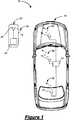
- FIG. 1is a top view of a vehicle that includes a passive entry system according to one non-limiting embodiment of the present disclosure
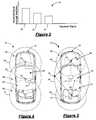
- FIG. 2is a graph illustrating an exemplary set of signals received by the passive entry system
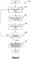
- FIG. 3is an exemplary flow diagram for determining the location of a FOB relative to the vehicle
- FIG. 4is another top view of the vehicle that includes an exemplary passive entry authorization area
- FIG. 5is another top view of the vehicle that includes an alternate exemplary passive entry authorization area
- FIG. 6is another top view of the vehicle that includes an alternate exemplary passive entry authorization area.
- a vehicle 10which may include a passive entry system, denoted generally by reference numeral 12 , according to one non-limiting aspect of the present disclosure.
- the passive entry system 12may include a vehicle controller 14 located within vehicle 10 .
- the vehicle controller 14may further include one or more transceiver units having a receiver and/or transmitter unit that communicate with one or more antennas 16 , 18 , 20 positioned about vehicle 10 .
- the present disclosurecontemplates that the transceiver units may be separate from the vehicle controller 14 and may be positioned about, or included in combination with antennas 16 , 18 , 20 .
- the vehicle controller 14may further be configured to operate a door lock mechanism (not shown), start the ignition of the vehicle 10 and/or perform a variety of other functions related to the operation of the vehicle 10 .
- the passive entry system 12may further include a remote hand held transmitter, which is conventionally referred to as a fob 22 , which may be carried and/or operated by an operator.
- the fob 22may be a separate unit, or may be part of an ignition key head.
- the fob 22may include a fob controller 24 having a transceiver unit.
- the transceiver unitmay include a transmitter and receiver for receiving and/or transmitting signals from the fob 22 .
- the present disclosurealso contemplates that the transceiver unit may be separate from the fob controller 24 .
- the fob 22may further include an antenna 26 configured to send and/or receive signals to and/or from antennas 16 , 18 , 20 .
- the present disclosurecontemplates that one or more signals 28 , 30 , 32 may be transmitted from the antennas 16 , 18 , 20 without an operator activating a switch or pushbutton on the fob 22 .
- the signals 28 , 30 , 32may include a wakeup signal intended to activate a corresponding fob 22 .
- the fob 22may receive the signals 28 , 30 , and determine the strength or intensity of the signals 28 , 30 , 32 .
- FIG. 2illustrates a graph 40 of the signals 28 , 30 , 32 respectively transmitted by antennas 16 , 18 , 20 that may be received by the fob 22 .
- the graph 40illustrates the strength or intensity of each received signal 28 , 30 , 32 , more commonly referred to as the Received Signal Strength Indication (RSSI).
- RSSIReceived Signal Strength Indication
- the fob controller 24may determine a position report indicating the distance of the fob 22 relative to each antenna 16 , 18 , 20 .
- the present disclosurecontemplates that the location of the fob 22 may also be determined using a predefined series of calibrated values that equate the determined RSSI value to a distance value.
- the fob 22may then transmit a response signal 34 that includes the position report to the antennas 16 , 18 , 20 .
- the vehicle controller 14may determine the location of the fob by verifying whether the received response signal 34 indicates that the fob 22 is located within a valid authorization zone. If so, the vehicle controller 14 may begin an authentication/response challenge sequence between the vehicle controller 14 and the fob 22 . Upon a successful authentication/response sequence, the vehicle controller 14 may determine whether a particular vehicle function should be performed if the fob 22 is within some pre-defined distance, or location, relative to the vehicle 10 .
- the controller 12may activate one or more door lock mechanisms (not shown) to unlock one or more of the vehicle doors.
- the vehicle controller 14may activate the ignition of the vehicle 10 .
- antenna 26 located within the fob 22may be configured to transmit long-range ultra-high frequency (UHF) signals to the antennas 16 , 18 , 20 of the vehicle 10 and receive short-range Low Frequency (LF) signals from the antennas 16 , 18 , of the vehicle 10 .
- UHFultra-high frequency
- LFLow Frequency
- the present disclosurecontemplates that separate antennas may be included within the fob 22 to transmit the UHF signal and receive the LF signal.
- the antennas 16 , 18 , 20may be configured to transmit LF signals to the fob 22 and receive UHF signals from the antenna 26 of the fob 22 .
- separate antennasmay be included within the vehicle 10 to transmit LF signals to the fob 22 and receive the UHF signal from the fob 22 .
- the fob 22may also be configured so that the fob controller 24 may be capable of switching between one or more UHF channels. As such, the fob controller 24 may be capable of transmitting the response signal 34 across multiple UHF channels. By transmitting the response signal 34 across multiple UHF channels, the fob controller 24 may ensure accurate communication between the fob 22 and the antennas 16 , 18 , 20 .
- FIG. 3illustrates an exemplary, flow diagram 200 according to one or more embodiments of the present application.
- the flow diagram 200 illustrated in FIG. 3is merely exemplary and the operation, function, or steps of the flow diagram 200 may be performed in a fashion other than the order described herein.
- the flow diagram 200may begin at operation 202 with an LF wakeup sequence that may include one or more wakeup signals being sent by the vehicle controller 14 to the fob 22 . Upon receiving the LF wakeup sequence, the flow diagram 200 may proceed to operation 204 .
- the fob controller 24may determine the RSSI of each received LF wakeup signal. Once the fob controller 24 determines the RSSI of each LF wakeup signal, the flow diagram 200 may proceed to operation 206 .
- the fob controller 24may transmit the fob response signal which includes the RSSI value of each antenna 16 , 18 , 20 as determined by the fob controller 24 . Once the fob response signal has been transmitted, the flow diagram proceeds to operation 208 .
- the vehicle controller 14determines the location of the fob 22 using the received fob response signal.
- the vehicle controller 14may determine the location by determining if the received fob response signal indicates that the fob 22 is within a predefined authorization zone.
- the authorization zonemay be established using a series of inclusion and exclusionary criteria based on the RSSI of each antenna 16 , 18 , 20 .
- the present disclosurecontemplates that the authorization zone may be any irregular geometrical shape so long as the span of the shape is confined to the coverage of the LF antennas.
- the fob controller 24may incorporate a triangulation verification procedure using the RSSI of each antenna 16 , 18 , 20 to determine if the fob 22 is located within the boundaries of the authorization zone.
- the fob controller 24may begin the triangulation verification procedure by first determining whether the fob 22 is located within any specified exclusion area. If the vehicle controller 14 determines that the fob 22 is located within one of the exclusionary areas, the fob 22 may be denied access to the authorization zone. If the fob controller 24 determines that the fob 22 is not located within at least one of the exclusion areas, then the fob controller 24 may determine if the fob 22 is located within at least one specified inclusion areas. If the fob controller 24 determines that the fob 22 is located within at least one of the inclusion areas, then the fob 22 may be allowed access to the requested authorization zone.
- FIG. 4illustrates an exemplary irregular shaped authorization area.
- each antenna 16 , 18 , 20may be configured to radiate a circular shape 40 , 42 , 44 .
- the radiation patternmay extend from a central point starting at each respective antenna 16 , 18 , 20 outward toward the circumference of each shape 40 , 42 , 44 .
- the vehicle controller 14may use the shapes 40 - 44 to define one or more authorization zones having a number of exclusion and inclusion areas.
- the fob controller 24may determine the authorization area based upon well known Boolean principles.
- the exclusion/inclusion area criterionmay be defined using following exemplary, equation: (a ⁇ X ⁇ b) AND (c ⁇ Y ⁇ d) AND (e ⁇ Z ⁇ f) (1)
- a geometrical interpretationmay be defined for the circular shapes 40 , 42 , and 44 .
- the vehicle controller 14may determine that the fob 22 is located within the authorization zone when the RSSI value of antenna 16 is greater than 100. Since each RSSI value may be converted to a distance value, there will be circle around each antenna 16 , 18 , 20 where the fob 22 may be detected.
- an inclusion/exclusion area criterionmay be defined using the following exemplary, equation: [(100 ⁇ X) AND (0 ⁇ Y) AND (0 ⁇ Z)] OR [(0 ⁇ X) AND (100 ⁇ Y) AND (0 ⁇ Z)] OR [(0 ⁇ X) AND (0 ⁇ Y) AND (100 ⁇ Z)] (2)
- the vehicle controller 14may determine that the fob 22 is within an excluded area only if the RSSI value of each antenna 16 , 18 , and 20 was determined to be zero (0). Conversely, if the vehicle controller 14 verifies that the RSSI value of antenna 16 , 18 , or 20 is greater or equal to 100, then the vehicle controller 14 will determine that the fob 22 is located within one of the inclusion areas.
- any number of authorization zones by be established by the vehicle controller 14may define the authorization areas as the region surrounding the vehicle doors using the following exemplary, equation: [(100 ⁇ X) AND (100 ⁇ Y)] OR (100 ⁇ Y) OR [(100 ⁇ Y) AND (100 ⁇ Z)] (3)
- the inclusion areas for FIG. 4may be defined as the areas 48 , 50 , and 52 .
- the exclusion areasmay be defined by areas 46 and 54 .
- the vehicle controller 14may first attempt to determine whether the fob 22 is located within at least one of the exclusion areas 46 and 54 . If yes, the vehicle controller 14 may deny the fob 22 access to the requested authorization zone. However, if the fob 22 is not located within at least one of the exclusion areas, the vehicle controller 14 may determine whether the fob 22 is located within at least one of the inclusion areas 48 , 50 , and 52 . If yes, the vehicle controller 14 may unlock one or more of the vehicle doors after a successful authentication security protocol is completed.
- FIG. 5illustrates that the authorization zone may be defined using only two of the antennas 16 , 20 .
- the authorization zonemay be determined using a pair of spherical or circular shapes 60 , 62 whose central point radiates outward from antennas 16 , 20 , respectively.
- each antenna 16 , 20may be used to define the foci of an elliptical shape 64 .
- the vehicle controller 14may use the elliptical shape 64 to define an authorization zone for the cabin area of the vehicle 10 .
- the fob controller 24may not need to determine the absolute location of the fob 22 using the triangulation verification procedure as described above with reference to FIG. 4 .
- an authorization zonemay be based on the signal amplitudes from each antenna 16 , 20 .
- the fob controller 24may determine the location of the fob 22 by verifying whether the fob 22 is located within the boundaries of elliptically shaped authorization zone.
- the present disclosurecontemplates that using elliptical interpolation to define the cabin area of the vehicle 10 may be advantageous since only two antennas are required. Furthermore, by using elliptical interpolation, the two antennas 16 , 20 may operate to define a pair of foci 76 , 78 of the elliptical shape 64 , as well as, a pair of radii 80 , 82 for each circular shape 60 , 62 . Hence, the two antennas 16 , 20 may operate to form three geometrical shapes (i.e., circular shapes 60 , 62 and elliptical shape 64 ).
- antennas 16 , 20may be positioned within the vehicle 10 so as to be along the major axis of the elliptical shape 64 . Furthermore, the antennas 16 , 20 may be positioned within the vehicle 10 so as to operate as a pair of foci 76 , 78 for the elliptical shape 64 . As such, the vehicle controller 14 may determine the curvature of the elliptical shape 64 by determining the major diameter and the distance between the pair of foci 76 , 78 . The present disclosure contemplates that the distance between the foci 76 , 78 may be determined by the vehicle controller 14 as the distance between antennas 16 , 20 .
- the vehicle controller 14may determine the major diameter by summing the distances from a point 79 along the elliptical shape 64 to the pair of foci 76 , 78 .
- the vehicle controller 14may also be capable of varying the size of the elliptical shape 64 by modifying the major diameter.
- the vehicle controller 14may be able to define the authorization zone for the elliptical shape 64 using the following, exemplary equation: ( X+Z ) ⁇ D (4) Where,
- the fob controller 24may determine that the fob 22 is located within the elliptical authorization area when the sum of the RSSI signals X and Z is greater than the constant that characterizes the elliptical shape 64 .
- the vehicle controller 14may determine the distance from the fob 22 to the antennas 16 , 20 by converting the RSSI values X and Z to distance values (X′, Z′). As such, the vehicle controller 14 may determine whether the fob 22 is located within the region of the elliptical shape 64 if the sum of distance values (X′, Z′) is less than the major diameter of the elliptical shape 64 .
- FIG. 6illustrates another non-limiting embodiment of the present disclosure.
- three antennas 16 , 18 , 20may be used to provide multiple authorization zones using both circular and elliptical shapes that cover the entire cabin area.
- a circular shape 84may be defined using antenna 16 .
- an elliptical shape 86may be formed using antennas 16 and 18 and another elliptical shape 88 may be formed using antennas 16 and 20 .
- another elliptical shape 90may be formed using antennas 18 and 20 .
- FIG. 6illustrates that three elliptical authorization zones 86 , 88 , and 90 may be established. Each elliptical authorization zone 86 , 88 , and 90 may allow the controller to more accurately determine the location of the fob 22 relative to the interior or exterior of the vehicle 10 . Furthermore, the use of three separate elliptical authorization zones 86 , 88 , and 90 may allow the vehicle controller 14 the ability to determine the location of the fob 22 without having to proceed with the triangulation verification procedure.
- flow diagram 200proceeds to operation 210 . However, if the vehicle controller 14 does not determine that the fob 22 is located within at least one of the authorization zones, flow diagram 200 proceeds back to operation 202 .
- the vehicle controller 14may begin the authentication security protocol with the fob 22 that is determined to be located within one of the authorization zones.
- the authentication security protocolmay include an authentication challenge signal transmitted by one or more of the antennas 16 , 18 , 20 .
- the fob 22may transmit a response authentication signal to the vehicle controller 14 . If the vehicle controller 14 determines the response authentication signal to be valid, the vehicle controller 14 may perform a particular vehicle operation (e.g., start the ignition of the vehicle or unlock one or more of the vehicle doors).
Landscapes
- Engineering & Computer Science (AREA)
- Physics & Mathematics (AREA)
- Electromagnetism (AREA)
- Computer Networks & Wireless Communication (AREA)
- Signal Processing (AREA)
- Quality & Reliability (AREA)
- Mechanical Engineering (AREA)
- Lock And Its Accessories (AREA)
Abstract
Description
(a≦X≦b) AND (c≦Y≦d) AND (e≦Z≦f) (1)
Where,
- X is the RSSI value of
antenna 16; - Y is the RSSI value of
antenna 18; - Z is the RSSI value of
antenna 20; - a, b, c, d, e, f are a set of predefined constants.
[(100≦X) AND (0≦Y) AND (0≦Z)] OR [(0≦X) AND (100≦Y) AND (0≦Z)] OR [(0≦X) AND (0≦Y) AND (100≦Z)] (2)
[(100≦X) AND (100≦Y)] OR (100≦Y) OR [(100≦Y) AND (100≦Z)] (3)
(X+Z)≧D (4)
Where,
- X is the RSSI value of
antenna 16; - Z is the RSSI value of
antenna 20; and - D is the constant value that may characterize the ellipse along with the distance between the two
foci
Claims (13)
Priority Applications (3)
| Application Number | Priority Date | Filing Date | Title |
|---|---|---|---|
| US12/644,442US8284020B2 (en) | 2009-12-22 | 2009-12-22 | Passive entry system and method for a vehicle |
| CN201010552804.4ACN102104435B (en) | 2009-12-22 | 2010-11-17 | Passive entry system and method for a vehicle |
| DE102010062092ADE102010062092B4 (en) | 2009-12-22 | 2010-11-29 | A system and method for determining the position of a remote transmitter in the vicinity of a vehicle |
Applications Claiming Priority (1)
| Application Number | Priority Date | Filing Date | Title |
|---|---|---|---|
| US12/644,442US8284020B2 (en) | 2009-12-22 | 2009-12-22 | Passive entry system and method for a vehicle |
Publications (2)
| Publication Number | Publication Date |
|---|---|
| US20110148573A1 US20110148573A1 (en) | 2011-06-23 |
| US8284020B2true US8284020B2 (en) | 2012-10-09 |
Family
ID=44150209
Family Applications (1)
| Application Number | Title | Priority Date | Filing Date |
|---|---|---|---|
| US12/644,442Expired - Fee RelatedUS8284020B2 (en) | 2009-12-22 | 2009-12-22 | Passive entry system and method for a vehicle |
Country Status (3)
| Country | Link |
|---|---|
| US (1) | US8284020B2 (en) |
| CN (1) | CN102104435B (en) |
| DE (1) | DE102010062092B4 (en) |
Cited By (15)
| Publication number | Priority date | Publication date | Assignee | Title |
|---|---|---|---|---|
| US20110109447A1 (en)* | 2009-11-11 | 2011-05-12 | Kabushiki Kaisha Tokai Rika Denki Seisakusho | Key locator for electronic key system |
| US20130181824A1 (en)* | 2011-07-19 | 2013-07-18 | Denso Corporation | Vehicle receiver system, vehicle receiver, and operating method for vehicle receiver |
| US20140022052A1 (en)* | 2012-07-19 | 2014-01-23 | Hyundai Mobis Co., Ltd. | Apparatus and method for controlling automatic opening of trunk |
| US20150184628A1 (en)* | 2013-12-26 | 2015-07-02 | Zhigang Fan | Fobless keyless vehicle entry and ingnition methodand system |
| US20150254913A1 (en)* | 2012-09-12 | 2015-09-10 | Nissan Motor Co., Ltd. | Control apparatus for vehicle opening/closing body |
| US9405944B2 (en) | 2013-04-25 | 2016-08-02 | Ford Global Technologies, Llc | Mitigation of LF interference from adjacent vehicles also using LF approach detection system |
| US20160272154A1 (en)* | 2013-11-01 | 2016-09-22 | Denso Corporation | Vehicle control apparatus |
| US9679430B2 (en) | 2013-03-08 | 2017-06-13 | Lear Corporation | Vehicle remote function system and method for determining vehicle FOB locations using adaptive filtering |
| US9852560B2 (en) | 2013-03-08 | 2017-12-26 | Lear Corporation | Vehicle remote function system and method for effectuating vehicle operations based on vehicle FOB movement |
| US20180151009A1 (en)* | 2016-11-28 | 2018-05-31 | Honda Motor Co., Ltd. | System and method for providing hands free operation of at least one vehicle door |
| US9988016B1 (en)* | 2016-12-07 | 2018-06-05 | Ford Global Technologies, Llc | Authentication of mobile devices for vehicle communication |
| US20180290626A1 (en)* | 2015-12-18 | 2018-10-11 | Bayerische Motoren Werke Aktiengesellschaft | Authorization of Use of a Motor Vehicle |
| US20180290625A1 (en)* | 2015-12-18 | 2018-10-11 | Bayerische Motoren Werke Aktiengesellschaft | Authorizing the Use of a Motor Vehicle |
| US10412581B2 (en) | 2017-02-14 | 2019-09-10 | Ford Global Technologies, Llc | Secure session communication between a mobile device and a base station |
| US10815717B2 (en)* | 2016-11-28 | 2020-10-27 | Honda Motor Co., Ltd. | System and method for providing hands free operation of at least one vehicle door |
Families Citing this family (61)
| Publication number | Priority date | Publication date | Assignee | Title |
|---|---|---|---|---|
| GB201119792D0 (en) | 2011-11-16 | 2011-12-28 | Jaguar Cars | Vehicle access system |
| US9554286B2 (en)* | 2011-12-02 | 2017-01-24 | Lear Corporation | Apparatus and method for detecting a location of a wireless device |
| JP5667038B2 (en)* | 2011-12-21 | 2015-02-12 | 株式会社東海理化電機製作所 | Vehicle electronic key system |
| US8638202B2 (en)* | 2012-04-12 | 2014-01-28 | GM Global Technology Operations LLC | Keyfob proximity theft notification |
| CN104379413B (en)* | 2012-05-22 | 2017-09-01 | Trw汽车美国有限责任公司 | Method and apparatus without opening door with hand |
| US20130342379A1 (en)* | 2012-06-25 | 2013-12-26 | Lear Corporation | Vehicle Remote Function System and Method |
| DE102012214201A1 (en)* | 2012-08-09 | 2014-05-22 | Bayerische Motoren Werke Aktiengesellschaft | Positioning with radio-based locking system |
| DE202012009510U1 (en)* | 2012-10-04 | 2012-12-06 | Stefan Flache | Identification of cats at medium distance. Device for the clear identification of cats in medium distances (greater than 10 centimeters to a few meters) in combination with a distance determination for the purpose of controlling an electronic cat flap |
| US9079560B2 (en)* | 2012-11-02 | 2015-07-14 | GM Global Technology Operations LLC | Device location determination by a vehicle |
| KR101362848B1 (en)* | 2012-12-14 | 2014-02-17 | 현대오트론 주식회사 | Method for detecting smart key around vehicle |
| CN103886657A (en)* | 2012-12-20 | 2014-06-25 | 李尔公司 | Remote function smart key to start communication between vehicle and device and method thereof |
| DE102014102271A1 (en)* | 2013-03-15 | 2014-09-18 | Maxim Integrated Products, Inc. | Method and device for granting an access permit |
| AU2013202164B2 (en)* | 2013-03-28 | 2016-05-12 | Robert Bosch (Australia) Pty Ltd | Method for determining the location of a remote transmitter positioned near a vehicle |
| KR101936961B1 (en)* | 2013-03-28 | 2019-01-09 | 현대자동차주식회사 | Hands-free system and method for opening trunk |
| JP2015072162A (en)* | 2013-10-02 | 2015-04-16 | パナソニックIpマネジメント株式会社 | Short-range wireless communication system for vehicle |
| US20150208207A1 (en)* | 2014-01-22 | 2015-07-23 | Lear Corporation | Wireless device localization |
| US20160059827A1 (en)* | 2014-08-27 | 2016-03-03 | Lear Corporation | Optimizing uwb satellite antenna in-vehicle positioning |
| KR102117028B1 (en) | 2014-10-07 | 2020-06-09 | 삼성전자주식회사 | Method and apparatus for pairing in a wireless communication system |
| TWI577586B (en)* | 2014-12-31 | 2017-04-11 | 鴻海精密工業股份有限公司 | Control system and control method for vehicle anti theft |
| US20160257198A1 (en) | 2015-03-02 | 2016-09-08 | Ford Global Technologies, Inc. | In-vehicle component user interface |
| DE102015206009B4 (en)* | 2015-04-02 | 2017-06-08 | Volkswagen Aktiengesellschaft | Distance determination and authentication of a radio key for a vehicle |
| TWI605965B (en)* | 2015-04-10 | 2017-11-21 | 鴻海精密工業股份有限公司 | Control system and method for vehicle electronic key |
| US10101433B2 (en)* | 2015-05-01 | 2018-10-16 | GM Global Technology Operations LLC | Methods for locating a vehicle key fob |
| US9825363B2 (en)* | 2015-05-18 | 2017-11-21 | Lear Corporation | Loop antenna for portable remote control device |
| FR3037410B1 (en)* | 2015-06-12 | 2019-09-13 | Valeo Comfort And Driving Assistance | DEVICE AND METHOD FOR DETERMINING THE PRESENCE OF AN IDENTIFIER, AND ASSOCIATED COMPUTER PROGRAM |
| US9721449B2 (en)* | 2015-09-29 | 2017-08-01 | Nissan North America, Inc. | Vehicle keyfob locator system |
| US9830757B2 (en)* | 2015-09-30 | 2017-11-28 | Faraday & Future Inc. | System and method for operating vehicle using mobile device |
| JP6561762B2 (en)* | 2015-10-21 | 2019-08-21 | 住友電気工業株式会社 | Vehicle communication system and in-vehicle device |
| US20170200334A1 (en)* | 2016-01-08 | 2017-07-13 | Ford Global Technologies, Llc | Personal device location authentication for secured function access |
| US9751458B1 (en)* | 2016-02-26 | 2017-09-05 | Ford Global Technologies, Llc | Vehicle illumination system |
| US9807570B1 (en)* | 2016-06-01 | 2017-10-31 | GM Global Technology Operations LLC | Systems and methods for detecting proximity and location of a smartphone or other device to a vehicle |
| US9924318B2 (en)* | 2016-07-01 | 2018-03-20 | Lear Corporation | Passive entry systems employing time of flight distance measurements |
| CN107662579A (en)* | 2016-07-27 | 2018-02-06 | 华晨汽车集团控股有限公司 | A kind of keyless entry activation system low-frequency calibration and the method for searching Intelligent key |
| JP6652040B2 (en)* | 2016-12-05 | 2020-02-19 | 株式会社Soken | Portable device position estimation system |
| KR102761490B1 (en)* | 2017-02-24 | 2025-02-03 | 삼성전자 주식회사 | Method and apparatus for authenticating car smart key |
| DE102017206119A1 (en)* | 2017-04-10 | 2018-10-11 | Bayerische Motoren Werke Aktiengesellschaft | A method, computer readable medium, system, and vehicle comprising the system for determining a location range of a mobile terminal relative to the vehicle |
| JP6794931B2 (en)* | 2017-06-05 | 2020-12-02 | トヨタ自動車株式会社 | Vehicle control system |
| JP6897415B2 (en)* | 2017-08-16 | 2021-06-30 | トヨタ自動車株式会社 | Vehicle control system |
| US11232658B2 (en) | 2017-11-20 | 2022-01-25 | Robert Bosch (Australia) Pty Ltd | Method and system for relay attack prevention |
| WO2019095021A1 (en)* | 2017-11-20 | 2019-05-23 | Robert Bosch (Australia) Pty Ltd | Method and system for relay attack prevention incorporating vector check |
| DE112018005903T5 (en) | 2017-11-20 | 2020-07-30 | Robert Bosch (Australia) Pty Ltd. | METHOD AND SYSTEM FOR PREVENTING RELAY ATTACKS INCLUDING MOTION |
| US10317517B1 (en) | 2018-05-15 | 2019-06-11 | Delphi Technologies, Llc | Vehicle location device |
| WO2020118362A1 (en)* | 2018-12-10 | 2020-06-18 | Robert Bosch (Australia) Pty Ltd | Method and system for relay attack prevention using subzones |
| CN109760629A (en)* | 2019-02-27 | 2019-05-17 | 深圳市维邦云计算技术发展有限公司 | Determine the circuit and method of vehicle remote control device position |
| DE112020001498T5 (en)* | 2019-03-25 | 2022-01-13 | Denso Corporation | Upsampling and cross-correlation for arrival time determinations in passive access/passive start systems |
| US12179699B2 (en) | 2019-04-18 | 2024-12-31 | Toyota Motor North America, Inc. | Systems and methods for countering security threats in a passive keyless entry system |
| US11443038B2 (en)* | 2019-04-18 | 2022-09-13 | Toyota Motor North America, Inc. | Systems and methods for countering security threats in a passive keyless entry system |
| US10946833B2 (en)* | 2019-06-24 | 2021-03-16 | Volkswagen Ag | Access device localization |
| US11598838B2 (en) | 2019-06-26 | 2023-03-07 | Aptiv Technologies Limited | Detection device |
| DE102019215535A1 (en)* | 2019-10-10 | 2021-04-15 | Continental Automotive Gmbh | Vehicle, comprising a radio device for a radio-based vehicle unlocking system, radio device for a vehicle and method for operating a vehicle |
| CN112744180B (en)* | 2019-10-29 | 2023-04-28 | 现代自动车株式会社 | System and method for connected vehicle control |
| JP7366816B2 (en)* | 2020-03-23 | 2023-10-23 | 株式会社東海理化電機製作所 | Control device, control system, and program |
| US11258480B2 (en)* | 2020-03-31 | 2022-02-22 | Nxp B.V. | System and method of optimized backup functionality for electronic control key |
| US11055941B1 (en)* | 2020-03-31 | 2021-07-06 | Nxp B.V. | System and method of improving security during backup functionality of electronic control key |
| US11449691B2 (en) | 2020-08-20 | 2022-09-20 | Assa Abloy Ab | Relay attack detection for interfaces using command-response pair |
| CN112505623B (en)* | 2020-11-18 | 2022-07-15 | 上海科世达-华阳汽车电器有限公司 | Low-frequency calibration method of PEPS system |
| CN112389369A (en)* | 2020-11-30 | 2021-02-23 | 嵊州市兰花电器科技有限公司 | Device for identifying position of automobile remote control key |
| US11650309B2 (en)* | 2021-01-08 | 2023-05-16 | Ford Global Technologies, Llc | Low-power vehicle sentinel systems and methods |
| JP7192005B2 (en)* | 2021-03-08 | 2022-12-19 | 本田技研工業株式会社 | VEHICLE CONTROL DEVICE AND VEHICLE CONTROL METHOD |
| US11991589B2 (en)* | 2021-03-31 | 2024-05-21 | Denso International America, Inc. | System and method of determining real-time location |
| CN112896094B (en)* | 2021-04-01 | 2022-12-20 | 上海科世达-华阳汽车电器有限公司 | An operation control method, system, device and vehicle |
Citations (37)
| Publication number | Priority date | Publication date | Assignee | Title |
|---|---|---|---|---|
| US4873530A (en) | 1985-09-30 | 1989-10-10 | Nissan Motor Co., Ltd. | Antenna device in automotive keyless entry system |
| US4942393A (en) | 1988-05-27 | 1990-07-17 | Lectron Products, Inc. | Passive keyless entry system |
| US5157389A (en) | 1989-11-02 | 1992-10-20 | Nissan Motor Co., Ltd. | Keyless vehicle lock system |
| US5499022A (en) | 1992-11-06 | 1996-03-12 | Valeo Electronique | Remote control system for locking and unlocking doors and other openings in a passenger space, in particular in a motor vehicle |
| US5751073A (en) | 1996-11-20 | 1998-05-12 | General Motors Corporation | Vehicle passive keyless entry and passive engine starting system |
| US5973611A (en) | 1995-03-27 | 1999-10-26 | Ut Automotive Dearborn, Inc. | Hands-free remote entry system |
| US6049268A (en) | 1999-08-03 | 2000-04-11 | Flick; Kenneth E. | Vehicle remote control system with less intrusive audible signals and associated methods |
| US6208239B1 (en) | 1998-10-10 | 2001-03-27 | Daimlerchrysler Ag | Procedure for the provision of access authorization to an engine-driven vehicle |
| US6236333B1 (en) | 1998-06-17 | 2001-05-22 | Lear Automotive Dearborn, Inc. | Passive remote keyless entry system |
| US6522241B1 (en) | 1999-04-06 | 2003-02-18 | Valeo Securite Habitacle | Motor vehicle equipped with a so-called “hands-free” access system |
| US6621178B2 (en) | 1999-12-10 | 2003-09-16 | Valeo Securite Habitacle | Motor vehicle equipped with a selective so-called “hands-free” access system |
| US6658328B1 (en) | 2002-01-17 | 2003-12-02 | Trw Inc. | Passive function control system for a motor vehicle |
| US20040005868A1 (en)* | 2002-07-05 | 2004-01-08 | Olivier Desjeux | Method for controlling access to a determined space via a personalised portable object, and portable object for implementing the same |
| US6778065B1 (en) | 1999-08-09 | 2004-08-17 | Honda Giken Kogyo Kabushiki Kaisha | Remote control system for a vehicle |
| US20040217850A1 (en) | 2003-04-29 | 2004-11-04 | Visteon Global Technologies, Inc. | Multistage vehicle security system |
| US20040227615A1 (en) | 2003-05-16 | 2004-11-18 | Lear Corporation | Keyless smart start system |
| US20040233047A1 (en) | 2003-05-23 | 2004-11-25 | King Ronald O. | Clamping circuit for an RF receiver system |
| US6853296B2 (en) | 2000-09-08 | 2005-02-08 | Peugeot Citroen Automobiles Sa | Method and device for automatically locking a motor vehicle |
| US6906612B2 (en) | 2002-04-11 | 2005-06-14 | Lear Corporation | System and method for vehicle passive entry having inside/outside detection |
| US6937136B2 (en) | 2000-09-19 | 2005-08-30 | Land Rover | Security system |
| US6943664B2 (en) | 2001-07-27 | 2005-09-13 | Siemens Vdo Automotive | Process for controlling the resynchronization of a remote control with a changing code |
| US6950008B2 (en) | 2001-10-04 | 2005-09-27 | Texas Instruments Deutschland Gmbh | Authentication of a first transceiver unit with respect to a second transceiver unit located at a distance |
| US7046119B2 (en) | 2004-05-19 | 2006-05-16 | Lear Corporation | Vehicle independent passive entry system |
| US20060114100A1 (en) | 2004-11-30 | 2006-06-01 | Riad Ghabra | Integrated passive entry and remote keyless entry system |
| US20060145809A1 (en) | 2002-11-19 | 2006-07-06 | Australian Narrow Pty Ltd. | Passive entry system |
| US7098769B2 (en) | 2000-12-29 | 2006-08-29 | Siemens Aktiengesellschaft | Identification system for verifying an authorization to access an object or to use an object, particularly a motor vehicle |
| US20060255908A1 (en) | 2005-05-13 | 2006-11-16 | Lear Corporation | Energy efficient passive entry system |
| US20060255906A1 (en) | 2005-05-12 | 2006-11-16 | Riad Ghabra | Method and apparatus for configuring passive entry system operation modes |
| US20070090965A1 (en) | 2005-10-21 | 2007-04-26 | Mc Call Clark E | Key-fob locating method and apparatus |
| US7230577B2 (en) | 2003-09-01 | 2007-06-12 | Omron Corporation | Wireless terminal position detecting device and method |
| US7245200B2 (en) | 2003-08-21 | 2007-07-17 | Mitsubishi Jidosha Kogyo Kabushiki Kaisha | Door unlocking controller and control method thereof |
| US20070200670A1 (en) | 2006-02-27 | 2007-08-30 | Denso International America, Inc. | Apparatus for automatically changing state of vehicle closure |
| US20080048829A1 (en)* | 2006-05-11 | 2008-02-28 | Alps Electric Co., Ltd. | Keyless entry device |
| US20080231416A1 (en) | 2007-03-21 | 2008-09-25 | Continental Automotive Systems Us, Inc. | Latency reduction in remote signal communication system |
| US20080232431A1 (en)* | 2007-03-19 | 2008-09-25 | Denso Corporation | Electronic key system and method |
| DE102008015477A1 (en) | 2007-03-29 | 2008-10-02 | Marquardt Gmbh | Closing system, particularly for access or driving authorization for vehicle in style of keyless entry or go function, has device, with two positions, formed as control device |
| US7446648B2 (en) | 2006-06-21 | 2008-11-04 | Lear Corporation | Passive activation vehicle system alert |
Family Cites Families (2)
| Publication number | Priority date | Publication date | Assignee | Title |
|---|---|---|---|---|
| WO2004102700A1 (en)* | 2003-05-15 | 2004-11-25 | Yuasa Corporation | Nonaqueous electrolyte battery |
| JP4439456B2 (en)* | 2005-03-24 | 2010-03-24 | 株式会社東芝 | Battery pack and automobile |
- 2009
- 2009-12-22USUS12/644,442patent/US8284020B2/ennot_activeExpired - Fee Related
- 2010
- 2010-11-17CNCN201010552804.4Apatent/CN102104435B/enactiveActive
- 2010-11-29DEDE102010062092Apatent/DE102010062092B4/ennot_activeExpired - Fee Related
Patent Citations (39)
| Publication number | Priority date | Publication date | Assignee | Title |
|---|---|---|---|---|
| US4873530A (en) | 1985-09-30 | 1989-10-10 | Nissan Motor Co., Ltd. | Antenna device in automotive keyless entry system |
| US4942393A (en) | 1988-05-27 | 1990-07-17 | Lectron Products, Inc. | Passive keyless entry system |
| US5157389A (en) | 1989-11-02 | 1992-10-20 | Nissan Motor Co., Ltd. | Keyless vehicle lock system |
| US5499022A (en) | 1992-11-06 | 1996-03-12 | Valeo Electronique | Remote control system for locking and unlocking doors and other openings in a passenger space, in particular in a motor vehicle |
| US5973611A (en) | 1995-03-27 | 1999-10-26 | Ut Automotive Dearborn, Inc. | Hands-free remote entry system |
| US5751073A (en) | 1996-11-20 | 1998-05-12 | General Motors Corporation | Vehicle passive keyless entry and passive engine starting system |
| US6236333B1 (en) | 1998-06-17 | 2001-05-22 | Lear Automotive Dearborn, Inc. | Passive remote keyless entry system |
| US6208239B1 (en) | 1998-10-10 | 2001-03-27 | Daimlerchrysler Ag | Procedure for the provision of access authorization to an engine-driven vehicle |
| US6522241B1 (en) | 1999-04-06 | 2003-02-18 | Valeo Securite Habitacle | Motor vehicle equipped with a so-called “hands-free” access system |
| US6049268A (en) | 1999-08-03 | 2000-04-11 | Flick; Kenneth E. | Vehicle remote control system with less intrusive audible signals and associated methods |
| US6778065B1 (en) | 1999-08-09 | 2004-08-17 | Honda Giken Kogyo Kabushiki Kaisha | Remote control system for a vehicle |
| US6621178B2 (en) | 1999-12-10 | 2003-09-16 | Valeo Securite Habitacle | Motor vehicle equipped with a selective so-called “hands-free” access system |
| US6853296B2 (en) | 2000-09-08 | 2005-02-08 | Peugeot Citroen Automobiles Sa | Method and device for automatically locking a motor vehicle |
| US6937136B2 (en) | 2000-09-19 | 2005-08-30 | Land Rover | Security system |
| US7098769B2 (en) | 2000-12-29 | 2006-08-29 | Siemens Aktiengesellschaft | Identification system for verifying an authorization to access an object or to use an object, particularly a motor vehicle |
| US6943664B2 (en) | 2001-07-27 | 2005-09-13 | Siemens Vdo Automotive | Process for controlling the resynchronization of a remote control with a changing code |
| US6950008B2 (en) | 2001-10-04 | 2005-09-27 | Texas Instruments Deutschland Gmbh | Authentication of a first transceiver unit with respect to a second transceiver unit located at a distance |
| US6658328B1 (en) | 2002-01-17 | 2003-12-02 | Trw Inc. | Passive function control system for a motor vehicle |
| US6906612B2 (en) | 2002-04-11 | 2005-06-14 | Lear Corporation | System and method for vehicle passive entry having inside/outside detection |
| US20040005868A1 (en)* | 2002-07-05 | 2004-01-08 | Olivier Desjeux | Method for controlling access to a determined space via a personalised portable object, and portable object for implementing the same |
| US20060145809A1 (en) | 2002-11-19 | 2006-07-06 | Australian Narrow Pty Ltd. | Passive entry system |
| US20040217850A1 (en) | 2003-04-29 | 2004-11-04 | Visteon Global Technologies, Inc. | Multistage vehicle security system |
| US20040227615A1 (en) | 2003-05-16 | 2004-11-18 | Lear Corporation | Keyless smart start system |
| US20040233047A1 (en) | 2003-05-23 | 2004-11-25 | King Ronald O. | Clamping circuit for an RF receiver system |
| US7245200B2 (en) | 2003-08-21 | 2007-07-17 | Mitsubishi Jidosha Kogyo Kabushiki Kaisha | Door unlocking controller and control method thereof |
| US7230577B2 (en) | 2003-09-01 | 2007-06-12 | Omron Corporation | Wireless terminal position detecting device and method |
| US7046119B2 (en) | 2004-05-19 | 2006-05-16 | Lear Corporation | Vehicle independent passive entry system |
| US20060114100A1 (en) | 2004-11-30 | 2006-06-01 | Riad Ghabra | Integrated passive entry and remote keyless entry system |
| US20060255906A1 (en) | 2005-05-12 | 2006-11-16 | Riad Ghabra | Method and apparatus for configuring passive entry system operation modes |
| DE102006016495A1 (en) | 2005-05-13 | 2006-11-23 | Lear Corp., Southfield | Energy-efficient passive locking system |
| US20060255908A1 (en) | 2005-05-13 | 2006-11-16 | Lear Corporation | Energy efficient passive entry system |
| US7292137B2 (en) | 2005-05-13 | 2007-11-06 | Lear Corporation | Energy efficient passive entry system |
| US20070090965A1 (en) | 2005-10-21 | 2007-04-26 | Mc Call Clark E | Key-fob locating method and apparatus |
| US20070200670A1 (en) | 2006-02-27 | 2007-08-30 | Denso International America, Inc. | Apparatus for automatically changing state of vehicle closure |
| US20080048829A1 (en)* | 2006-05-11 | 2008-02-28 | Alps Electric Co., Ltd. | Keyless entry device |
| US7446648B2 (en) | 2006-06-21 | 2008-11-04 | Lear Corporation | Passive activation vehicle system alert |
| US20080232431A1 (en)* | 2007-03-19 | 2008-09-25 | Denso Corporation | Electronic key system and method |
| US20080231416A1 (en) | 2007-03-21 | 2008-09-25 | Continental Automotive Systems Us, Inc. | Latency reduction in remote signal communication system |
| DE102008015477A1 (en) | 2007-03-29 | 2008-10-02 | Marquardt Gmbh | Closing system, particularly for access or driving authorization for vehicle in style of keyless entry or go function, has device, with two positions, formed as control device |
Non-Patent Citations (1)
| Title |
|---|
| German Patent Office, Office Action for the corresponding German Patent Application No. 10 2010 062 092.0 mailed Mar. 16, 2012. |
Cited By (29)
| Publication number | Priority date | Publication date | Assignee | Title |
|---|---|---|---|---|
| US8400285B2 (en)* | 2009-11-11 | 2013-03-19 | Kabushiki Kaisha Tokai Rika Denki Seisakusho | Key locator for electronic key system |
| US20110109447A1 (en)* | 2009-11-11 | 2011-05-12 | Kabushiki Kaisha Tokai Rika Denki Seisakusho | Key locator for electronic key system |
| US20130181824A1 (en)* | 2011-07-19 | 2013-07-18 | Denso Corporation | Vehicle receiver system, vehicle receiver, and operating method for vehicle receiver |
| US8847744B2 (en)* | 2011-07-19 | 2014-09-30 | Toyota Jidosha Kabushki Kaisha | Vehicle receiver system, vehicle receiver, and operating method for vehicle receiver |
| US20140022052A1 (en)* | 2012-07-19 | 2014-01-23 | Hyundai Mobis Co., Ltd. | Apparatus and method for controlling automatic opening of trunk |
| US9214083B2 (en)* | 2012-07-19 | 2015-12-15 | Hyundai Mobis Co., Ltd. | Apparatus and method for controlling automatic opening of trunk |
| US20150254913A1 (en)* | 2012-09-12 | 2015-09-10 | Nissan Motor Co., Ltd. | Control apparatus for vehicle opening/closing body |
| US9721408B2 (en)* | 2012-09-12 | 2017-08-01 | Nissan Motor Co., Ltd. | Control apparatus for vehicle opening/closing body |
| US9679430B2 (en) | 2013-03-08 | 2017-06-13 | Lear Corporation | Vehicle remote function system and method for determining vehicle FOB locations using adaptive filtering |
| US9852560B2 (en) | 2013-03-08 | 2017-12-26 | Lear Corporation | Vehicle remote function system and method for effectuating vehicle operations based on vehicle FOB movement |
| US9405944B2 (en) | 2013-04-25 | 2016-08-02 | Ford Global Technologies, Llc | Mitigation of LF interference from adjacent vehicles also using LF approach detection system |
| US20160272154A1 (en)* | 2013-11-01 | 2016-09-22 | Denso Corporation | Vehicle control apparatus |
| US9751497B2 (en)* | 2013-11-01 | 2017-09-05 | Denso Corporation | Vehicle control apparatus |
| US20150184628A1 (en)* | 2013-12-26 | 2015-07-02 | Zhigang Fan | Fobless keyless vehicle entry and ingnition methodand system |
| US10562494B2 (en)* | 2015-12-18 | 2020-02-18 | Bayerische Motoren Werke Aktiengesellschaft | Authorization of use of a motor vehicle |
| US10703334B2 (en)* | 2015-12-18 | 2020-07-07 | Bayerische Motoren Werke Aktiengesellschaft | Authorizing the use of a motor vehicle |
| US20180290626A1 (en)* | 2015-12-18 | 2018-10-11 | Bayerische Motoren Werke Aktiengesellschaft | Authorization of Use of a Motor Vehicle |
| US20180290625A1 (en)* | 2015-12-18 | 2018-10-11 | Bayerische Motoren Werke Aktiengesellschaft | Authorizing the Use of a Motor Vehicle |
| US20180151009A1 (en)* | 2016-11-28 | 2018-05-31 | Honda Motor Co., Ltd. | System and method for providing hands free operation of at least one vehicle door |
| US20190295348A1 (en)* | 2016-11-28 | 2019-09-26 | Honda Motor Co., Ltd. | System and method for providing hands free operation of at least one vehicle door |
| US20190295346A1 (en)* | 2016-11-28 | 2019-09-26 | Honda Motor Co., Ltd. | System and method for providing hands free operation of at least one vehicle door |
| US10510200B2 (en)* | 2016-11-28 | 2019-12-17 | Honda Motor Co., Ltd. | System and method for providing hands free operation of at least one vehicle door |
| US10515499B2 (en)* | 2016-11-28 | 2019-12-24 | Honda Motor Co., Ltd. | System and method for providing hands free operation of at least one vehicle door |
| US10380817B2 (en)* | 2016-11-28 | 2019-08-13 | Honda Motor Co., Ltd. | System and method for providing hands free operation of at least one vehicle door |
| US10740993B2 (en)* | 2016-11-28 | 2020-08-11 | Honda Motor Co., Ltd. | System and method for providing hands free operation of at least one vehicle door |
| US10815717B2 (en)* | 2016-11-28 | 2020-10-27 | Honda Motor Co., Ltd. | System and method for providing hands free operation of at least one vehicle door |
| US11080952B2 (en)* | 2016-11-28 | 2021-08-03 | Honda Motor Co., Ltd. | System and method for providing hands free operation of at least one vehicle door |
| US9988016B1 (en)* | 2016-12-07 | 2018-06-05 | Ford Global Technologies, Llc | Authentication of mobile devices for vehicle communication |
| US10412581B2 (en) | 2017-02-14 | 2019-09-10 | Ford Global Technologies, Llc | Secure session communication between a mobile device and a base station |
Also Published As
| Publication number | Publication date |
|---|---|
| CN102104435B (en) | 2014-08-06 |
| DE102010062092A1 (en) | 2011-06-30 |
| DE102010062092B4 (en) | 2012-11-22 |
| CN102104435A (en) | 2011-06-22 |
| US20110148573A1 (en) | 2011-06-23 |
Similar Documents
| Publication | Publication Date | Title |
|---|---|---|
| US8284020B2 (en) | Passive entry system and method for a vehicle | |
| KR101947909B1 (en) | Method, computer program and apparatus for checking an authorization of a mobile communication device | |
| US10293786B1 (en) | Method and system for secure access to a vehicle | |
| US11351962B2 (en) | Electronic key system | |
| US8427289B2 (en) | Low latency inside/outside determination for portable transmitter | |
| US10235823B1 (en) | Passive entry system of a vehicle having relay attack prevention | |
| US7705710B2 (en) | Method for a start and access system for a motor vehicle | |
| US20210011143A1 (en) | Distance measurement system | |
| KR101771376B1 (en) | Vehicle control system to prevent relay attack | |
| US6906612B2 (en) | System and method for vehicle passive entry having inside/outside detection | |
| US9728025B2 (en) | Portable device, communication device, and communication system | |
| US8872620B2 (en) | Wireless key system and key location determination method | |
| US20050038574A1 (en) | Identification system for verifying an authorization for access to an object, or use of an object, in particular a motor vehicle | |
| US20150371471A1 (en) | Passive Entry System and Method for a Vehicle | |
| US20210166508A1 (en) | Communications system of a vehicle | |
| JP2020118030A (en) | Electronic key system | |
| US10744977B2 (en) | Method for controlling access to a motor vehicle | |
| US8620490B2 (en) | Method to disable trunk lockout protection for smart entry | |
| WO2014017056A1 (en) | On-board apparatus control system | |
| US20060176147A1 (en) | Vehicle security system | |
| WO2017104373A1 (en) | Vehicle control system | |
| JP2019085734A (en) | Electronic key system for vehicles | |
| CN106571843A (en) | Vehicle and vehicle-mounted central control system | |
| US12026322B2 (en) | Method for activating a function of a vehicle by ultra high frequency with an item of portable user equipment and device for activating an associated function | |
| US20070257841A1 (en) | Method And Apparatus For Localizing A Mobile Transmitter Embodied As An Identification Device, Especially A Vehicle Key |
Legal Events
| Date | Code | Title | Description |
|---|---|---|---|
| AS | Assignment | Owner name:LEAR CORPORATION, MICHIGAN Free format text:ASSIGNMENT OF ASSIGNORS INTEREST;ASSIGNORS:GHABRA, RIAD;YAKOVENKO, NIKOLAY;GIRARD, HILTON (JERRY) W., III;REEL/FRAME:023688/0639 Effective date:20091222 | |
| AS | Assignment | Owner name:JPMORGAN CHASE BANK, N.A., AS ADMINISTRATIVE AGENT Free format text:SECURITY AGREEMENT;ASSIGNOR:LEAR CORPORATION;REEL/FRAME:026468/0182 Effective date:20110617 | |
| STCF | Information on status: patent grant | Free format text:PATENTED CASE | |
| AS | Assignment | Owner name:JPMORGAN CAHSE BANK, N.A., AS AGENT, ILLINOIS Free format text:SECURITY INTEREST;ASSIGNOR:LEAR CORPORATION;REEL/FRAME:030076/0016 Effective date:20130130 Owner name:JPMORGAN CHASE BANK, N.A., AS AGENT, ILLINOIS Free format text:SECURITY INTEREST;ASSIGNOR:LEAR CORPORATION;REEL/FRAME:030076/0016 Effective date:20130130 | |
| AS | Assignment | Owner name:LEAR CORPORATION, MICHIGAN Free format text:RELEASE BY SECURED PARTY;ASSIGNOR:JPMORGAN CHASE BANK, N.A., AS AGENT;REEL/FRAME:037701/0318 Effective date:20160104 | |
| AS | Assignment | Owner name:LEAR CORPORATION, MICHIGAN Free format text:RELEASE BY SECURED PARTY;ASSIGNOR:JPMORGAN CHASE BANK, N.A., AS AGENT;REEL/FRAME:037702/0911 Effective date:20160104 | |
| FPAY | Fee payment | Year of fee payment:4 | |
| MAFP | Maintenance fee payment | Free format text:PAYMENT OF MAINTENANCE FEE, 8TH YEAR, LARGE ENTITY (ORIGINAL EVENT CODE: M1552); ENTITY STATUS OF PATENT OWNER: LARGE ENTITY Year of fee payment:8 | |
| FEPP | Fee payment procedure | Free format text:MAINTENANCE FEE REMINDER MAILED (ORIGINAL EVENT CODE: REM.); ENTITY STATUS OF PATENT OWNER: LARGE ENTITY | |
| LAPS | Lapse for failure to pay maintenance fees | Free format text:PATENT EXPIRED FOR FAILURE TO PAY MAINTENANCE FEES (ORIGINAL EVENT CODE: EXP.); ENTITY STATUS OF PATENT OWNER: LARGE ENTITY | |
| STCH | Information on status: patent discontinuation | Free format text:PATENT EXPIRED DUE TO NONPAYMENT OF MAINTENANCE FEES UNDER 37 CFR 1.362 | |
| FP | Lapsed due to failure to pay maintenance fee | Effective date:20241009 |