US8283812B2 - Inductive power providing system having moving outlets - Google Patents
Inductive power providing system having moving outletsDownload PDFInfo
- Publication number
- US8283812B2 US8283812B2US12/757,286US75728610AUS8283812B2US 8283812 B2US8283812 B2US 8283812B2US 75728610 AUS75728610 AUS 75728610AUS 8283812 B2US8283812 B2US 8283812B2
- Authority
- US
- United States
- Prior art keywords
- primary
- inductor
- power
- primary inductor
- detector
- Prior art date
- Legal status (The legal status is an assumption and is not a legal conclusion. Google has not performed a legal analysis and makes no representation as to the accuracy of the status listed.)
- Active
Links
Images


Classifications
- H—ELECTRICITY
- H01—ELECTRIC ELEMENTS
- H01F—MAGNETS; INDUCTANCES; TRANSFORMERS; SELECTION OF MATERIALS FOR THEIR MAGNETIC PROPERTIES
- H01F38/00—Adaptations of transformers or inductances for specific applications or functions
- H01F38/14—Inductive couplings
- H—ELECTRICITY
- H02—GENERATION; CONVERSION OR DISTRIBUTION OF ELECTRIC POWER
- H02J—CIRCUIT ARRANGEMENTS OR SYSTEMS FOR SUPPLYING OR DISTRIBUTING ELECTRIC POWER; SYSTEMS FOR STORING ELECTRIC ENERGY
- H02J50/00—Circuit arrangements or systems for wireless supply or distribution of electric power
- H02J50/005—Mechanical details of housing or structure aiming to accommodate the power transfer means, e.g. mechanical integration of coils, antennas or transducers into emitting or receiving devices
- H—ELECTRICITY
- H02—GENERATION; CONVERSION OR DISTRIBUTION OF ELECTRIC POWER
- H02J—CIRCUIT ARRANGEMENTS OR SYSTEMS FOR SUPPLYING OR DISTRIBUTING ELECTRIC POWER; SYSTEMS FOR STORING ELECTRIC ENERGY
- H02J50/00—Circuit arrangements or systems for wireless supply or distribution of electric power
- H02J50/10—Circuit arrangements or systems for wireless supply or distribution of electric power using inductive coupling
- H—ELECTRICITY
- H02—GENERATION; CONVERSION OR DISTRIBUTION OF ELECTRIC POWER
- H02J—CIRCUIT ARRANGEMENTS OR SYSTEMS FOR SUPPLYING OR DISTRIBUTING ELECTRIC POWER; SYSTEMS FOR STORING ELECTRIC ENERGY
- H02J50/00—Circuit arrangements or systems for wireless supply or distribution of electric power
- H02J50/40—Circuit arrangements or systems for wireless supply or distribution of electric power using two or more transmitting or receiving devices
- H02J50/402—Circuit arrangements or systems for wireless supply or distribution of electric power using two or more transmitting or receiving devices the two or more transmitting or the two or more receiving devices being integrated in the same unit, e.g. power mats with several coils or antennas with several sub-antennas
- H—ELECTRICITY
- H02—GENERATION; CONVERSION OR DISTRIBUTION OF ELECTRIC POWER
- H02J—CIRCUIT ARRANGEMENTS OR SYSTEMS FOR SUPPLYING OR DISTRIBUTING ELECTRIC POWER; SYSTEMS FOR STORING ELECTRIC ENERGY
- H02J50/00—Circuit arrangements or systems for wireless supply or distribution of electric power
- H02J50/70—Circuit arrangements or systems for wireless supply or distribution of electric power involving the reduction of electric, magnetic or electromagnetic leakage fields
- H—ELECTRICITY
- H02—GENERATION; CONVERSION OR DISTRIBUTION OF ELECTRIC POWER
- H02J—CIRCUIT ARRANGEMENTS OR SYSTEMS FOR SUPPLYING OR DISTRIBUTING ELECTRIC POWER; SYSTEMS FOR STORING ELECTRIC ENERGY
- H02J50/00—Circuit arrangements or systems for wireless supply or distribution of electric power
- H02J50/90—Circuit arrangements or systems for wireless supply or distribution of electric power involving detection or optimisation of position, e.g. alignment
- H—ELECTRICITY
- H02—GENERATION; CONVERSION OR DISTRIBUTION OF ELECTRIC POWER
- H02J—CIRCUIT ARRANGEMENTS OR SYSTEMS FOR SUPPLYING OR DISTRIBUTING ELECTRIC POWER; SYSTEMS FOR STORING ELECTRIC ENERGY
- H02J7/00—Circuit arrangements for charging or depolarising batteries or for supplying loads from batteries
- H02J7/0047—Circuit arrangements for charging or depolarising batteries or for supplying loads from batteries with monitoring or indicating devices or circuits
- H—ELECTRICITY
- H01—ELECTRIC ELEMENTS
- H01F—MAGNETS; INDUCTANCES; TRANSFORMERS; SELECTION OF MATERIALS FOR THEIR MAGNETIC PROPERTIES
- H01F5/00—Coils
- H01F5/003—Printed circuit coils
- Y—GENERAL TAGGING OF NEW TECHNOLOGICAL DEVELOPMENTS; GENERAL TAGGING OF CROSS-SECTIONAL TECHNOLOGIES SPANNING OVER SEVERAL SECTIONS OF THE IPC; TECHNICAL SUBJECTS COVERED BY FORMER USPC CROSS-REFERENCE ART COLLECTIONS [XRACs] AND DIGESTS
- Y10—TECHNICAL SUBJECTS COVERED BY FORMER USPC
- Y10T—TECHNICAL SUBJECTS COVERED BY FORMER US CLASSIFICATION
- Y10T29/00—Metal working
- Y10T29/49—Method of mechanical manufacture
- Y10T29/49826—Assembling or joining
Definitions
- the present disclosureis directed to an inductive power system having movable inductive power outlets.
- a ring main to which the power sockets are connectedmay be provided.
- Such a ring mainis typically embedded in the wall, and electrical boxes in/on the wall are connected therewith. The location of power outlets is thus determined by the locations of the fixed electrical boxes. Once the wall has been finished, the relocation of power outlets is difficult.
- additional wiringmust be provided.
- the additional wiringmay itself be located within or embedded into the wall by chiseling a groove into the surface thereof, running the wiring along the groove and rendering over the wiring, with plaster, pointing compound or the like.
- Additional power outletsare typically either sunk into depressions cut into the wall surface or alternatively, protruding electrical boxes are screwed or bolted there onto.
- Another method for relocating power outletsis to attach a power conduit to the outside of the wall and to run wiring through the external conduit, with power outlets being connected to the external conduit.
- Such a solutionis commonly used in schools, colleges, laboratories and other institutions, particularly where the walls are constructed from solid stone, concrete or brick. It will be appreciated that this solution is costly, time consuming and unsightly.
- U.S. Pat. No. 3,585,565 to Pricedescribes an electrical tape and plug connector designed to facilitate and simplify the installation of electrical wiring.
- Substantially flat or film conductorsare sandwiched between insulating layers of protective material.
- the sandwich constructionincludes a ground conductor insulated from the two mains current carrying conductors.
- One surface or side of the tape or cableis coated with a pressure-sensitive adhesive.
- a three-prong connectoradapts the tape or cable to a utility outlet.
- Price's solutionallows wiring to lie flat against a wall surface which makes the wiring less obtrusive and simpler to install.
- installation of the utility outletsrequires the removal of insulation from the conducting tape and the connection of a special plug.
- the utility outlet once connectedcannot be removed without exposing the conductor.
- Changdescribes an electric wire coupling device which includes one or more electric wires having one or more electric cables engaged and received in an outer rubber covering.
- One or more socketseach has a socket housing and two conductor members secured in the socket housing, which are aligned with the orifices of the socket housing for receiving plugs.
- the electric wires and/or the socketseach has an adhesive material for attaching to the supporting wall without further fasteners.
- the socketmay include a side opening for coupling to the other electric wires.
- Conventional electrical socketshave holes therein into which the pins of corresponding plugs are inserted to form a conductive coupling.
- the power supplying side of the coupleis generally the female part, and does not have bare conductive elements protruding therefrom.
- the plug coupled to the deviceis the corresponding male part, typically having bare pins.
- the size of the pins and holesare such that even a small child cannot insert his or her fingers thereinto.
- an earth connectionis provided, and, only when a plug with a longer earth pin is inserted there into, is it possible to insert a pin (or anything else) into the holes connected to the current carrying live and neutral wires. Nevertheless, children do occasionally manage to insert pencils, pins and other objects into socket holes, sometimes with fatal results. Water can also cause shorting and may result in electrocution.
- socketsare unsightly, the number of sockets installed on a wall is generally limited. Often, their position is not appropriate to changing requirements and extension cords are needed.
- the inductive power outletcomprising at least one primary inductor connectable to a power supply via a driver; the driver for providing an oscillating voltage supply to the primary inductor; the primary inductor for inductively coupling with a secondary inductor wired to an electric load.
- the bounding surfaceis selected from the group comprising: walls, floors, ceilings, sinks, baths, doors and work surfaces.
- the inductive power outletsare incorporated into prefabricated materials for incorporating into the bounding surfaces.
- the prefabricated materialsare selected from the group comprising: plasterboard, paper sheets, wallpaper, plasterers tape, doors, window frames, wall-tiles, fitted cabinets, kitchen counters, sinks, baths, sink surrounds, rugs, fitted carpets, parquet, linoleum, floor-tiles, non-slip matting, tiling, stone, artificial stone and paving.
- a plasterboard panelfor affixing into the bounding surface, the plasterboard panel comprising a layer of gypsum sandwiched between two paper sheets and at least one pair of conductors for connecting the primary inductor to the power supply, the primary inductor being behind at least one of the paper sheets.
- the plasterboard panelis additionally characterized by at least one feature selected from:
- the disclosureprovides a paper sheet for adhering to the bounding surface; the paper sheet comprising the at least one primary inductor; and at least one pair of conductors for connecting the primary inductor to the power supply.
- the paper sheetmay be characterized by at least one feature selected from:
- a tapefor affixing onto the bounding surface, the tape comprising:
- the power outlet tapeis characterized by at least one feature selected from the group comprising:
- a floor surface for the workspaceis provided, the primary inductor being embedded therein and wired to the power supply via wiring under the floor surface.
- the floor surfaceis selected from the group comprising: rugs, fitted carpets, parquet, linoleum, floor-tiles, non-slip matting, tiling, stone, artificial stone and paving.
- an electrical applianceis adapted to draw power inductively from at least one inductive power outlet, the electrical appliance comprising at least one secondary inductor.
- the electrical appliancefurther comprising a power storage means, for storing electrical energy for powering the appliance.
- the power storage meansis selected from the group comprising capacitors, accumulators, and rechargeable electrochemical cells.
- the electrical applianceis selected from the group comprising: standing lamps, video recorders, DVD players, paper shredders, fans, photocopiers, computers, printers, cooking appliances, refrigerators, freezers, washing machines, clothes dryers, heavy machinery, desk lamps, ambient lighting units, fans, wireless telephones, speakers, speaker phones, conference call base units, electric pencil sharpeners, electric staplers, display devices, electrical picture frames, VDUs, projectors, televisions, video players, music centers, calculators, scanners, fax machines, hot plates, electrically heated mugs, mobile phones, hairdryers, shavers, delapidators, heaters, wax-melting equipment, hair curlers, beard trimmers, bathroom-scales, lights and radios, egg beaters, bread-makers, liquidizers, orange juice extractors, vegetable juicers, food-processors, electric knives, toasters, sandwich toasters, waffle makers, electrical barbecue grills, slow cookers, hot-plates, deep-fat fryers, electrical frying pans, knife
- a systemcomprising a power platform that comprises at least one device-mounted inductive power outlet for inductively providing power to electrical loads, the system further comprising at least one secondary inductor for drawing power inductively from at least one inductive power outlet with the power platform being incorporated into an item of furniture.
- the item of furnitureis selected from the group comprising chairs, tables, workbenches, partitioning walls cabinets and cupboards.
- the inductive power outletcomprises a positioning mechanism for moving the primary inductor behind the bounding surface.
- the inductive power outletis further characterized by at least one feature selected from the group comprising:
- the positioning mechanismcomprises at least one rail upon which the primary inductor is slideably mounted.
- the railis slideably supported by at least one of the group comprising tracks and pulleys.
- the systemfurther comprising at least one indicator for indicating the location of the primary inductor.
- the systemis further characterized by at least one feature selected from:
- the systemincludes an indicator comprising an emitter of radiation of a type and intensity capable of penetrating the substantially opaque layer and for allowing detection thereof from in front of the substantially opaque layer.
- the systemis further characterized by at least one feature selected from the group comprising:
- the protection systemfurther comprises: at least one primary detector for detecting power transmitted by the primary inductor; at least one secondary detector for detecting the secondary inductor inductively coupled to the primary inductor; and at least one controller in communication with both the primary detector and the secondary detector, for triggering the circuit-breaker.
- the primary detectoris selected from the group comprising: magnetic sensors, heat sensors, electromagnetic radiation sensors and Hall probes.
- the primary inductor of the protection systemradiates at a characteristic frequency f and the primary detector being configured to detect radiation at frequency f.
- the protection systemadditionally comprises a modulator for tagging the radiation with a secondary tag indicating that the secondary inductor is inductively coupled to the primary inductor, wherein the secondary detector comprises a processor for demodulating the radiation and isolating the secondary signal.
- Certain embodimentsadditionally comprise a modulator for tagging the radiation with a primary tag uniquely identifying the primary inductor.
- Step (b)may be selected from at least one of the steps:
- Step (c)may be selected from at least one of the steps:
- Step (d)comprises sending at least one control signal to a controller indicating that the primary inductor is transmitting power with no secondary inductor present, and sending a trigger signal to a circuit-breaker connected between the power supply and the primary inductor.
- FIG. 1is a schematic diagram of a corner of a room, incorporating a power providing system according to one embodiment of the present disclosure
- FIG. 2is a schematic representation of a plaster board wall panel including a plurality of primary inductive coils and connecting wires for coupling to a mains power supply;
- FIG. 3is a schematic representation of a wall incorporating the plasterboard wall panel of FIG. 2 ;
- FIG. 4is a schematic representation of a wallpaper including a plurality of primary inductive coils and connecting wires for coupling to a mains power supply;
- FIG. 5is a schematic representation of a wall coated with the wallpaper of
- FIG. 4
- FIG. 6is a schematic representation of a wall incorporating primary inductive coils connected to a control box
- FIG. 7shows an exemplary configuration of the electrical components embedded in a section of walling according to a further embodiment of the disclosure
- FIG. 8 ais a schematic representation of a roll of power outlet tape
- FIG. 8 bis a schematic representation of a second, wider power outlet tape having a two dimensional array of primary inductive coils thereupon;
- FIG. 9 ais a schematic representation of the power outlet tape of FIG. 8 a being applied to a wall;
- FIG. 9 bis a schematic representation of various appliances provided with dedicated inductive power adaptors, mounted upon the completed wall of FIG. 9 a;
- FIG. 9 cis a schematic representation of an inductive power adaptor mounted to a wall
- FIG. 10 ashows a first configuration of the electrical components of the power outlet tape
- FIG. 10 bshows a second configuration of the electrical components of the power outlet tape
- FIG. 11shows an under-floor power providing system in accordance with a further embodiment of the present disclosure
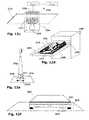
- FIG. 12 a - fare schematic representations of various embodiments of electrical appliances provided with secondary coils, adapted to receive power from inductive outlets;
- FIG. 13 a - dare schematic representations of further embodiments of electrical appliances, adapted to receive power from inductive outlets;
- FIG. 14 ais a schematic representation of a surface incorporating a movable power outlet, with a portable computer inductively coupled therewith according to another embodiment of the current disclosure
- FIG. 14 bis a cross section through a surface layer behind which a power outlet is mounted upon a first embodiment of a positioning mechanism
- FIG. 15 ais a schematic representation of a wall including a linear rail behind the skirting board thereof to which a power outlet is slidably mounted and free to be moved by a second embodiment of a positioning mechanism;
- FIG. 15 bis a schematic representation of two power outlets slidably mounted to an extended rail covering a wall;
- FIG. 15 cis a schematic representation of a third embodiment of a positioning mechanism wherein a power outlet is mounted upon an adjustable H-frame behind a wall;
- FIG. 15 dis a schematic representation of a fourth embodiment of a positioning mechanism wherein a power outlet is movable by four guiding cables behind a surface;
- FIGS. 16 a and 16 bshow sections through a movable inductive outlet including a clutch mechanism engaged and disengaged to the surface;
- FIG. 17 ais a schematic representation of a concealed power outlet and an indicator incorporated into a surface for indicating the location of a primary coil concealed behind the surface;
- FIG. 17 bis a schematic representation of a computer resting upon the surface of FIG. 17 a and being powered by the concealed primary coil;
- FIG. 17 cis a schematic representation of an alternative power outlet, wherein an adjustable primary coil is concealed behind a wall and controllable remotely by a control panel which indicates the location of the primary coil;
- FIG. 18 ais a schematic representation of a power outlet, wherein a light emitting diode transmits a location beam which is received by a camera of a mobile phone;
- FIG. 18 bis a block diagram representing a power outlet according to another embodiment of the disclosure, wherein a primary coil is configured to transmit a locator beam, carrying an encoded signal identifying the location of the primary coil, to a receiver;
- FIG. 19is a block diagram of a power-leak prevention system for use in a power providing system according to another embodiment of the present disclosure.
- FIG. 20 ais a schematic diagram of an inductive power outlet protected by a local leak prevention system, and a secondary coil, wired to an electric load, inductively coupled thereto, in accordance with another embodiment of the present disclosure
- FIG. 20 bis a schematic diagram of the inductive power outlet of FIG. 20 a without a secondary coil inductively coupled thereto;
- FIG. 21is a schematic diagram of a plurality of inductive power outlets protected by a remote leak prevention system according to a further embodiment of the present disclosure.
- FIG. 22is a flow-chart illustrating a method for preventing an inductive power outlet from transmitting power in the absence of an electric load coupled therewith, according to still another embodiment of the present disclosure.
- FIG. 1showing a schematic diagram of a power providing system according to an exemplary embodiment of the present disclosure.
- a workspace 1such as a corner of a room, bounded by walls 2 a , 2 b , a ceiling 2 c and a floor 2 d , contains a variety of electrical appliances 4 , such as a television set 4 a and a light fixture 4 b , for example.
- Such electrical appliances 4are adapted to draw power from inductive power outlets 6 . It is a particular feature of one aspect of the disclosure that inductive power outlets are incorporated into the bounding surfaces 2 of the room, such as the walls, ceiling and flooring thereof.
- Inductive power couplingallows energy to be transferred from a power supply to an electric load without a conduction path being provided therebetween.
- a power supplyis wired to a primary inductor and an oscillating electric potential is applied across the primary inductor which induces an oscillating magnetic field.
- the oscillating magnetic fieldmay induce an oscillating electrical current in a secondary inductor placed close to the primary inductor.
- electrical energymay be transmitted from the primary inductor to the secondary inductor by electromagnetic induction without the two inductors being conductively connected.
- the pairare said to be inductively coupled.
- An electric load wired in series with such a secondary inductormay draw energy from the power source when the secondary inductor is inductively coupled to the primary inductor.
- primary inductors 7are wired to a power source, such as the electric mains for example, via a controller.
- the controllerprovides the electronics to drive the primary coil.
- Such electronicsmay include, for example, a switching unit providing a high frequency oscillating voltage across the primary inductor for driving same.
- Electrical devices 4may receive power from the inductive power outlets via secondary inductors 5 configured to inductively couple with the primary inductors 7 of the inductive power outlets 6 .
- secondary inductors 5may be housed in inductive receiving units wired to the electrical devices 2 . In other embodiments, secondary inductors may be incorporated into the electrical devices themselves.
- inductive power outletsmay be incorporated into prefabricated building materials.
- a plasterboard panel 100in accordance with one embodiment of the disclosure is shown.
- the plasterboard panel 100consists of a layer of building material 102 , such as gypsum or the like, sandwiched between facing sheets 104 , 106 , that are typically of paper.
- Built into the plasterboard panel 100are one or more primary inductors 108 A-F and connecting wires 110 , 112 that extend to the edge of the panel 100 allowing it to be coupled to a mains power supply (not shown).
- the primary inductors 108 A-Fmay be embedded within the building material 102 .
- the primary inductors such as inductive coils 108 A-Fmay be relatively thin and may simply be adhered or stuck onto the facing sheet 104 designed to be the outer facing surface of the panel 100 .
- the primary inductors 108 a - f and conducting wires 110 , 112may be fabricated from wires or metal foil, such as an aluminum or copper sheet. Alternatively, the primary inductive coils 108 a - f and conducting wires 110 , 112 may be printed or painted onto the facing sheet 104 using conductive inks
- Flux guidance coresmay improve the electromagnetic coupling of primary coils 108 with secondary coils 604 ( FIG. 6 ) brought into proximity with them.
- flux guidance cores(not shown) for example of ferrite or amorphous ferromagnetic material are associated with each primary coil and embedded in the walling. Further components such as ferromagnetic shielding elements or the like may additionally be incorporated therein.
- the plasterboard panel 100may be incorporated into a wall 200 , such as a standard drywall comprising panels 202 of plasterboard mounted onto a framework 204 .
- plasterboard panel 100may usefully be fabricated from ‘green’ water-resistant plasterboard.
- plasterboardis used rather loosely herewith and may refer to other building materials, particularly those used for dry-walling, such as gypsum, plasterboard, gyproc, sheetrock or the like.
- the wallpaper 300comprises a flexible sheet 302 of a laminar material that is typically a paper or fabric, the front surface 301 of which may be printed or patterned.
- a plurality of primary inductive coils 308are provided on the back 304 of the flexible sheet 302 .
- the primary coils 308may be fabricated from a metal foil and adhered onto the flexible sheet 302 , or may comprise conductive inks printed onto the flexible sheet 302 by silk screening for example.
- the wall paper 300is designed to be stuck onto the surface of a wall 400 .
- the primary coils 308are configured to inductively couple with secondary inductive coils 602 ( FIG. 6 ).
- secondary inductive coils 602may be carried by power adaptors 420 used to provide power outlets attached to the surface 402 of the wall 400 ; with secondary inductive coils wired to electrical devices, such as light fixtures 460 or televisions 480 , for example; or on furniture such as tables and the like (not shown), brought into proximity with the wall, and having conventional power sockets or inductive power outlets thereupon.
- Power adaptors 420may be secured to walls 400 using adhesives, or may be screwed or bolted into place. Alternatively, magnets may be embedded into the wall to magnetically couple with corresponding magnets within the power adaptors 420 . Power adaptors 420 may be readily exchanged between different power points without the need for additional wiring. It will be appreciated that power adaptors 420 may be incorporated within appliances such as a television 480 , music system or the like. It is further noted that a single appliance such as a television 480 may span more than one primary inductive coil 308 , thereby allowing the appliance to draw power from more than one power point. This may be useful in various applications, such as where the power needed by an appliance is greater than the power that may be supplied by a single primary inductive coil 308 , for example.
- the material from which the flexible sheet 302 is fabricatedmay usefully be heavily patterned or textured to conceal electrical components thereunder, such as primary inductive coils 308 on the back thereof, and electrical conducting strips 310 , 312 extending to the edge of the paper 300 for coupling to a mains power supply.
- the paper 300has an adhesive surface 306 on the back surface thereof, for adhering to a wall 400 .
- Self adhesive, pre-glued wallpapers per se.are known, and technologies thereof may be adapted for the inductive papers described herein.
- a waxy release layer or backing sheet 307such as a low density polyethylene or the like is adhered to the self adhesive layer 306 .
- the backing sheet 307may be peeled off, enabling the paper 300 to be adhered to a surface, such as a wall 400 , via the adhesive surface 306 thereby exposed.
- the front surface 301may be coated with a waxy release material coating, such that when rolled up the self adhesive layer 306 is easily separated manually. Other possibilities will present themselves to wallpaper hangers.
- control boxes 500may be hard-wired to a ring main 540 to provide the electronics to drive the primary coils 508 embedded or adhered to the walling 510 .
- Driving electronicsmay be provided.
- thesemay include a switching unit providing high frequency oscillating voltage supply and an outlet selector for selecting the power outlet to be driven.
- the control box 500may be connected to the primary coils 508 by crimple connectors 520 such as flat PCB connectors for example.
- Optionally connecting power tape 560may be provided having no primary inductive coils but having conducting strips (not shown) for connecting between the walling 510 and a control box 500 .
- a power adaptor 600may include a secondary inductive coil 602 hard wired to a conventional power jack 604 to which a conventional power plug (not shown) may be coupled.
- the secondary inductive coil 604may be hardwired directly to an electric load such as a light fixture 460 or the like.
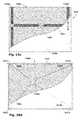
- a common electrical conducting strip 710connects with all the primary inductive coils 708 within a column.
- a control strip 712consists of a bundle of conducting wires each of which is connected to only one of the primary inductive coils 708 . Wherever the power walling is severed, the common electrical conducting strip 710 and the control strip 712 may be connected to a control box 500 ( FIG. 6 ). The control strip 712 thus provides a means for selectively activating each primary inductive coil individually.
- the configuration of electrical components described aboveprovides control of individual primary coils. It will be appreciated, however, that alternative configurations of electrical components are possible, as will be apparent to persons skilled in the art.
- plasterers tapeis used to cover over joints in the plaster board.
- Plasterer's tapetypically a scrim or hessian paper tape, helps to maintain the integrity of the surface and reduces the risk of the plaster cracking along the joints.
- Self adhesive plasterer's tapeis known, such as that described by Stough in U.S. Pat. No. 5,486,394. Stough's tape assists in rapid taping of seams between adjacent drywall units, and is provided in rolls.
- the tapehas a first layer of flexible paper material with an inwardly facing pressure-sensitive adhesive coating thereon.
- a second layer of reinforcing woven fiber materialoverlies the first layer.
- a third layer of flexible materialoverlies the woven fiber material to encapsulate the fiber material between the first layer and the second layer.
- the third layerhas an outwardly facing release coating such that the first layer adhesive will releasably engage the third layer for manual separation of the tape when rolled upon itself.
- a creaseis formed along the center of the tape to facilitate positioning of the tape in a wall corner.
- the self release properties of the tapeallow it to be easily dispensed and applied without the need to remove a backing
- the adhesiveis formulated to maintain adhesion even when wetted by an overlying layer of drywall mud.
- the release coating on the third layeraccepts and allows the adherence of drywall mud such as jointing compound, plaster and the like.
- FIG. 8 ashowing a roll of power outlet tape 800 incorporating inductive power outlets 842 according to another embodiment of the disclosure.
- the power outlet tape 800is constructed from three layers.
- the first layer 820has a pressure sensitive adhesive surface 822 which may be adhered to a surface such as a wall.
- the second layer 840holds the electrical components which include a series of power outlets 842 and electrical conducting strips 844 , 846 .
- the third layer 860overlies the second layer 840 thereby sandwiching the electrical components between the first 820 and third layer 860 .
- the electrical components of the second layer 840are electrical conducting strips 844 , 846 and a series of primary inductive coils 842 .
- the primary inductive coils 842are configured to inductively couple with secondary inductive coils carried by power adaptors which may be used to provide power outlets upon the surface of a wall.
- the outer surface 862 of the third layer 860may be coated with a waxy release material coating such as a low density polyethylene or the like, such that when rolled up the adhesive surface 822 of the first layer is easily separated from the outer surface 862 of the third layer 860 , typically by hand.
- a releasable cover slip(not shown) covered in a waxy release material may be adhered to the adhesive layer 822 to protect the adhesive surface from gathering dust and the like as well as to prevent the tape 800 from prematurely sticking to objects.
- FIG. 8 bshows an alternative embodiment of a power outlet tape 800 ′ comprising a two dimensional array 840 ′ of primary inductive coils 842 ′. Three rows of primary inductive coils are provide each having its own pair of conducting strips 844 ′ a - c , 846 ′ a - c . It is noted that such a roll of tape 800 ′ may be useful for covering large areas for example table tops, work surfaces or the like. Thus the alternative power outlet tape 800 ′ may be used to provide an array of remote power points.
- the power tape 800is shown being applied to a wall 900 .
- Drywall boards 920 of materialsuch as gypsum, plasterboard, gyproc, sheetrock or the like are mounted to a framework 940 .
- the segments of power outlet tape 800are used to bridge between the adjacent drywall boards 920 .
- the drywall boards 920 and taped seams 960create a substantially flat surface upon which plaster 980 may be applied.
- plaster 980 containing ferromagnetic materialmay provide additional flux guidance for the inductive couplings.
- the bridging functionhas been performed by a paper, hessian or other scrim tape with no embedded electrical components.
- the ends of the power outlet tape segmentsmay be connected to the control box 500 by means of crimple connectors 520 such as flat PCB connectors for example.
- crimple connectors 520such as flat PCB connectors for example.
- Optionally connecting power tape(not shown) may be provided having no primary inductive coils but including conducting strips for connecting between the power outlet tape 800 and a remote control box 500 .
- Control boxes 500which are hard wired to a ring main 540 , provide the electronics to drive the primary induction coils 842 , such as a switching unit providing high frequency oscillating voltage supply and an outlet selector for selecting the power outlet to be driven.
- Inductive power adaptorsare used to provide power to wall-mounted appliances as shown in FIGS. 9 b and 9 c .
- a fully plastered wall 950is shown, concealing two segments of power outlet tape 810 a , 810 b each having five power points at each of which is located a primary inductive coil 842 a - j .
- Each segment 810 a , 810 bis connected to a control box 500 a , 500 b which is hard wired to a ring main 540 .
- exemplary appliance unitsinclude, inter alia: a single jack power adaptor 420 , a double jack power adaptor 440 , a light fixture power adaptor 460 and a wall mounted television 480 .
- Power adaptors 420 , 440 , 460may be secured to the walls using adhesives or screwed into place.
- magnetsmay be embedded into the wall to magnetically couple with magnets in the adaptors 420 , 440 , 460 .
- the power adaptors 420 , 440 , 460are thus readily exchanged between power points without the need for any further wiring.
- power adaptorsmay be embedded in appliances such as a television 480 , a music system or the like. It is noted that a single appliance such as the television 480 shown in FIG. 9 b may span more than one primary inductive coil 842 g , 842 h , thereby allowing the appliance to draw power from more than one power point if required, for example where the power needed is greater than the power supplied by a single primary inductive coil 842 .
- FIG. 9 ca representation of an inductive power adaptor 600 is shown coupled to a power point 842 along a segment of power outlet tape 810 which is connected to a control box 500 .
- a secondary inductive coil 602is hard wired to a conventional power jack 604 which may be coupled to a conventional power plug.
- the secondary inductive coil 604may be hardwired directly to an electric load such as a light fixture or the like.
- FIGS. 10 a and 10 bTwo embodiments of the power outlet tape are shown in FIGS. 10 a and 10 b .
- the electrical components 840are configured such that a common electrical conducting strip 844 connects with the primary inductive coils 842 along the tape.
- a control strip 846may consist of a bundle of conducting wires each of which is connected to only one of the primary inductive coils 842 .
- a segment of the power outlet tapeis detached from the roll, by severing the tape, perhaps by manual tearing or by using a cutting implement such as a pair of scissors or a knife.
- the common electrical conducting strip 844 and the control strip 846may be connected to a control box 500 .
- the control strip 846may be used to selectively activate each primary inductive coil 842 .
- FIG. 10 bA second embodiment of the electrical components 640 of the power outlet tape is shown in FIG. 10 b .
- each primary inductive coil 642is connected to its own pair of dedicated conducting strips 644 , 646 .
- the conducting strip pairs from each primary inductive coil 642extend along the power outlet tape for a length sufficient that severing the tape along any line provides access to three pairs of conducting strips.
- severing the tape of the second embodiment along the line Afor example provides contacts to the pairs of conducting strips 644 b - d , 646 b - d controlling each of the following three primary inductive coils 642 b , 642 c , 642 d .
- U.S. Pat. No. 6,444,962 to Reicheltdescribes a heating arrangement that consists of at least one heating element in the form of a flat element with two opposite-lying, essentially parallel conductors and a coating arranged therebetween for the generation of electromagnetic waves.
- the coating materialis comprised of a binding agent, an insulating agent, a dispersion agent, water and graphite.
- the heating devicealso comprises a control device with a harmonic generator containing an electric component that has a rapid rate of current rise and is suitable for generating a high harmonic content.
- the harmonic generatoris coupled to both electric conductors of the heating element in order to emit a spectrum of vibrations in natural molecular frequency ranges.
- a low-cost, highly effective heating systemis thus provided, which, in one embodiment, is a flat panel that can be provided in coiled up form similar to wallpaper.
- flat, wall mounted heating elementsthat may be incorporated within wallpaper are known.
- inductive coils 6 or ferromagnetic shields having relatively high internal resistancesuch that in addition to inducing an electrical current, the oscillation of an electrical current therein additionally produces a heating effect.
- a heating effectmay be used as a convection heater for heating the room 1 , and usefully, inductive coils having high resistivity are situated under the floor 2 d or beneath a window, thereby facilitating effective heat circulation in the room.
- floor mounted inductive power outlets 1200are wired via underfloor wiring 1220 to a power source (not shown) either directly or via a control unit (not shown).
- the primary inductive coil units 1200are configured to inductively couple with secondary coils 1300 placed thereabove, that are themselves coupled to electrical loads 1320 , 1325 . In this manner, open floor sockets are avoided.
- the system 1100 as herein describedmay be used with a variety of flooring types such as rugs, fitted carpet, parquet, linoleum, floor tiles, tiling, paving and the like.
- Floor mounted devices 1320such as a standing lamp 1320 a or a photocopier 1320 b , with secondary power coils 1300 in the bases thereof may be situated directly above the floor mounted primary coils 1200 .
- furniture 1325such as a desk 1325 a or a chair 1325 b with secondary coil 1300 therein may be placed over the floor mounted primary coils 1200 and may serve as platforms for providing power to electrical devices 1340 placed thereupon such as a reading lamp 1340 a , or desktop appliances 1340 such as a laptop computer 1340 b or a novelty coffee mug 1340 c which directly heats the liquid therein.
- Such devices 1340may be hardwired to furniture 1325 , plugged into sockets (not shown) on the table top or may themselves include secondary coils 1500 and interface with primary coils 1400 on the surface of the table top 1326 .
- secondary coils 1200may be incorporated for aligning with primary coils 1200 of the system 1100
- household appliancessuch as standing lamps, televisions, music centers, video recorders, DVDs, and, if suitable wattage is made available, even washing machines, clothes dryers and the like, as well as cooking appliances such as ovens, cookers, hot-plates, fridges and freezers for example.
- the system 1100may be provided to power typically floor mounted devices such as paper shredders, fans, photocopiers, computers, printers or heavy machinery.
- furniture 1325may be provided with primary coils 1400 incorporated therewithin for coupling with secondary coils 1500 associated with worktop appliances. Furniture into which such primary coils may be embodied include chairs, tables, workbenches, partitioning walls, cupboards or such like.
- Worktop appliances having integral secondary coils 1500which may be aligned with the primary coils 1400 incorporated within a tabletop 1326 for example include desk lamps, ambient lighting units, fans, wireless telephones, speakers, speaker phones, conference call base units, electric pencil sharpeners, electric staplers, display devices, electrical picture frames, VDUs, projectors, televisions, videos, music centers, computers, calculators, scanners, printers, fax machines, photocopiers, paper shredders, hot plates, electrically heated mugs and mobile phones.
- Bathroom wallsare often tiled with ceramic tiles and sink surrounds are typically fabricated from natural or artificial polished stone, stainless steel, ceramic, or acrylics to provide easily cleaned surfaces that may be repeatedly washed.
- bathroom electricity socketsare typically covered with waterproof coverings. It will be appreciated that power outlet sockets, are less easily cleaned than such work-surfaces, since the socket holes for plug pins, and switches must be kept dry to prevent short circuits, or worse, electrocution.
- FIG. 12 aa schematic representation of an electrical appliance, such as a music player 2010 is shown.
- a secondary coil 2012is provided in the base 2014 thereof.
- the electrical appliance 2010may be powered by placing it on a surface 2016 , such as a sink surround, incorporating a primary inductive coil 2018 , so that the secondary coil 2012 is aligned with the primary coil 2018 .
- the primary coil 2018is wired to a power supply 2019 via a driver 2017 which provides the electronics to drive the primary coil 2018 .
- Driving electronicsmay include a switching unit providing a high frequency oscillating voltage supply, for example.
- the primary coilmay be concealed behind a facing layer 2015 of the bathroom surface, such as a ceramic sink surround or wall tile.
- the primary coilmay also be incorporated in the wall or door of a bathroom cabinet, behind a vinyl or Formica surface layer, for example.
- a primary coilmay be concealed beneath or within the floor such as under or within a rug, fitted carpet, parquet, linoleum, floor tiles, tiling, paving and the like, enabling an appliance to be placed on the floor and operated without being plugged in by a visible power cord.
- the primary coilmay be incorporated within a sink or bathtub, whether ceramic or acrylic.
- FIG. 12 bis a schematic representation of an electrical appliance 2210 having a secondary coil 2212 connected therewith via a flex 2211 , with a vacuum sucker arrangement 2213 for attaching the secondary coil 2212 to a surface 2026 , over a primary coil 2218 therewithin.
- the primary coil 2218is connected to a power supply 2219 via a driver 2217 .
- suckers 2213are provided in proximity with the secondary coil 2212 , for attaching the secondary coil 2212 over the primary coil 2218 .
- light fittings 2310in accordance with embodiments of the present disclosure may be fully insulated from the power source 2302 by a dielectric material 2304 , and provided with a secondary coil 2312 .
- the primary coil 2318may be incorporated within green, i.e. water-proof plasterboard 2320 , for example.
- an alternative, safe approach to providing light in the bathroomis provided.
- Drawer 2400is provided with one or more primary coils 2418 .
- the base 2404 thereofmay be covered with one large rectangular primary coil 2418 coupled to a mains power supply (not shown).
- a plurality of rechargeable appliancessuch as electrical toothbrushes 2424 , hair dryers 2426 and shavers 2428 may be recharged by providing the appliances with secondary coils (not shown) and placing them within the drawer 2400 .
- a dedicated stand 2500may be provided, with dedicated primary coils 2518 thereon for recharging specific appliances.
- a toothbrush holder 2500 with a primary coil 2518 thereinmay be provided for recharging one or more electrical toothbrushes 2524 storable therewithin, via a secondary coil 2512 thereupon.
- a digital bathroom scale 2600 with a secondary coil 2612 therebeneathmay be positioned over a primary coil 2618 embedded in the floor 2620 , or placed under a bathmat (not shown).
- Certain appliancessuch a refrigerators, freezers, stoves and dishwashers are power hungry, large devices that tend to be plugged into dedicated sockets, and are rarely moved, apart from to allow cleaning of the space thereunder and therebehind. Such devices are well served by conventional, conductive power technology.
- such devicesshould be usable on any available work surface, including the draining board by the sink, countertops, table top and the like.
- the well designed kitchen of the prior arthas double power outlet sockets set into the walls above all such work-surfaces, enabling such occasionally used devices to be plugged in and used where desired.
- Kitchenswhich are used for the preparation of food for human consumption, should be kept hygienically clean. Walls are often tiled with ceramic tiles and counter tops are typically fabricated from polished stone, stainless steel, or Formica, to provide an easily cleaned surface that may be repeatedly washed. It will be appreciated that power outlet sockets, are less easily cleaned than such work-surfaces, since the socket holes for plug pins, and switches must be kept dry to prevent short circuits, or worse, electrocution.
- Kettlesare particularly problematic, as they need to be regularly refilled from the tap (faucet).
- the kettleshould be disconnected from the electric power supply, and in properly designed kitchens, sockets are not located close to sinks, and kettle wires are kept short.
- the cords of kettlescan usually be disconnected at the point of connection to the kettle. Should this point of connection get wet however, there is a real danger of short-circuiting and blowing or tripping a fuse, which is inconvenient, and also prevents a real danger of electrocution which is rather more serious.
- FIG. 13 aa schematic representation is shown of an electrical appliance 3120 , specifically, a toaster.
- a secondary coil 3124is provided in the base 3122 thereof.
- the electrical appliance 3120may be powered by placing it on a work surface 3140 incorporating a primary inductive coil 3144 , so that the secondary coil 3124 is aligned with the primary coil 3144 .
- the electrical appliance 3120may be any of a wide range of appliances or gadgets such as egg beaters, bread-makers, liquidizers, orange juice extractors, vegetable juicers, food-processors, electric knives, sandwich toasters, waffle makers, electrical barbecue grills, slow cookers, hot-plates, deep-fat fryers, electrical frying pans, knife sharpeners and domestic sterilizers, kettles, urns, radios, cassette players, CD players and electrical tin-openers.
- appliances or gadgetssuch as egg beaters, bread-makers, liquidizers, orange juice extractors, vegetable juicers, food-processors, electric knives, sandwich toasters, waffle makers, electrical barbecue grills, slow cookers, hot-plates, deep-fat fryers, electrical frying pans, knife sharpeners and domestic sterilizers, kettles, urns, radios, cassette players, CD players and electrical tin-openers.
- the primary coil 3144is wired to a power supply 3160 via a driver 3180 which provides the electronics to drive the primary coil 3144 .
- Driving electronicsmay include a switching unit providing a high frequency oscillating voltage supply, for example.
- the primary coil 3144may be concealed behind a facing layer 3142 of the kitchen work-top, or table.
- the facing layermay be a sheet of sticky back plastic, vinyl, Formica or wood veneer, for example.
- a primary coilmay be concealed beneath or within the floor such as under or within a rug, fitted carpet, parquet, linoleum, floor tiles, tiling, paving and the like, enabling the domestic appliance to be placed on the floor and operated.
- primary coilsmay be placed into a resin that hardens as artificial marble, which is a polymer matrix composite including mineral filler, such as solid surface building materials, for example Corian® or the so-called, Caesar® Stone, manufactured in Israel.
- Caesar® stonemay be cast with sinks and drainers built in. Unlike real stone that needs drilling from behind to provide a primary inductive coil near the upper surface thereof, where desired, Caesar stone and similar composite materials, including concrete, may be cast around inclusions such as metal objects including inductive coils and connecting wires.
- FIG. 13 bis a schematic representation of an exemplary electrical appliance 3120 , again represented by a toaster, having a secondary coil 3124 connected therewith via a flex 3126 , with a vacuum sucker arrangement 3129 for attaching the secondary coil 3124 to a work-surface 3140 , over a primary coil 3144 therewithin.
- the primary coil 3144may be incorporated within a horizontal surface 3140 , such as a kitchen worktop.
- the primary coilmay be concealed behind or within a vertical surface such as a wall of a building or a cabinet, for example within ceramic wall tiles, behind wallpaper behind a Formica cupboard door or wall, or the like.
- the appliances of FIGS. 13 a and 13 bmay additionally include a socket 3128 for connecting a power cable for conductive power supply, by plugging into a conventional, conductive mains power socket.
- a retractable cord 3123that is coilable within the base 3122 of the appliance 3120 c is provided.
- a power storage means 3125may be provided, for storing power, enabling the device to be charged and used where no inductive or conductive power is available. This makes appliances in accordance with the disclosure, truly portable, and usable on any work surface.
- Embodiments of the present disclosureare directed to appliances including capacitors or electrochemical power storage devices designed to provide appropriate power to power electrical motors for a number of seconds to two or three minutes, and are thus appropriate for powering food processors, toasters, kettles, and the like.
- a storage area 3000such as a drawer or cupboard having primary charging coils 3121 in the base thereof is shown. Appliances with a chargeable component 3125 ( FIG. 13 c ) may be stored in storage area 3000 , for removal therefrom and use. In this way the chargeable component 3125 is fully charged when needed.
- the power outletsare generally fixed in predetermined locations. According to other embodiments of the present disclosure, the power outlets are movable to suit changing requirements.
- a movable power outlet 4100for providing power to an electrical device, specifically a computer 4182 .
- a primary coil 4120adjacent to the back face 4142 of a surface layer 4140 , is affixed to a positioning mechanism 4160 .
- the primary coil 4120is configured to inductively couple with a secondary coil 4180 wired to the computer 4182 .
- the positioning mechanism 4160is configured to move the primary coil 4120 behind the surface layer 4140 so that the primary coil 4120 may be repositioned.
- the primary coil 4120is wired to a power source typically via a controller (not shown) providing the electronics to drive the primary coil 4120 .
- Driving electronicsmay include a switching unit, providing a high frequency oscillating voltage supply, for example.
- the power outlet 4100may be incorporated into a vertical surface such as a wall of a building or a cabinet.
- the primary coil 4120may be moved behind a surface layer 4140 of wall paper or stretched canvas for example.
- the power outlet 4100may be incorporated behind a facing layer of a horizontal platform such as a desk-top, a kitchen work-top, a conference table or a work bench for example of mica, Formica or wood veneer.
- the primary coils 4120are configured to move beneath flooring such as rugs, fitted carpet, parquet, linoleum, floor tiles, tiling, paving and the like.
- the primary coil 4120is sandwiched between the surface layer 4140 and a base layer 4162 .
- the primary coil 4120is wound around a ferrite core 4124 affixed to a carriage 4161 , mounted upon a roller-ball 4163 and is configured to roll over the base layer 4162 .
- a magnetic element 4166such as iron, steel or preferably a permanent magnet, is affixed to the carriage 4161 .
- the magnetic element 4166is configured to be pulled by a nearby attracting magnetic element 4168 situated upon the front face 4144 of the surface layer 4140 . Moving the attracting magnetic element 4168 across the plane of the surface 4140 drags the magnetic element 4166 , thereby dragging the primary coil 4120 beneath the surface layer 4140 and positioning it as required.
- the carriage 4161may be mounted upon other elements such as wheels, skis, levitating magnetic elements or the like.
- movement of the positioning mechanism 4160may further be assisted by coating abutting surfaces with low-friction materials, such as Teflon® (PTFE).
- PTFETeflon®
- a primary coil unit 5120is slidably mounted to a rail 5162 .
- the rail 5162may run horizontally behind the skirting board 5142 of a wall 5140 for example.
- the primary coil unit 5120is configured to be movable into various positions along the rail 5162 .
- the primary coil unit 5120may be pulled manually by magnets as in the embodiment of FIG. 15 a .
- the primary coil unit 5120may be mounted upon motorized wheels 5164 and configured to drive itself along the rail 5162 .
- the rail 5162may be straight or curved and may even snake back and forth to cover an extended area of the wall 5140 , as shown in FIG. 15 b .
- more than one primary coil units 5120 bmay be independently positionable. Alternatively a plurality of primary coil units may be moved together.
- FIG. 15 cshowing a third embodiment of the positioning mechanism 5160 c in which a primary coil unit 5120 is slidably mounted to a boom rail 5162 , which is slidably supported by a pair of generally perpendicular supporting tracks 5164 to form an adjustable H-frame 5165 .
- a primary coil unit 5120is slidably mounted to a boom rail 5162 , which is slidably supported by a pair of generally perpendicular supporting tracks 5164 to form an adjustable H-frame 5165 .
- the position of the primary coil unit 5120may be moved behind a surface layer 5140 .
- the supporting tracks 5164may be replaced by supporting pulleys.
- Such pulleysmay be used to support the boom rail 5162 which may be lowered and raised by adjusting the pulleys either manually or by a driving motor.
- the primary coil unit 5120may be suspended from a pulley mounted to trolley configured to run horizontally along a fixed gantry beam spanning the width of the wall.
- a primary coil unit 5120is affixed to four guiding cables 5169 a - d .
- the lengths of the guiding cables 5169 a - dare independently controlled by pulleys 5167 a - d , located at four points defining the corners of a quadrilateral 5166 .
- the position of the primary coil unit 5120may be manipulated by the pulleys 5167 into any position within the quadrilateral 5166 . It will be apparent that other configurations of three or more pulleys may be used to manipulate the primary coil unit 5120 over two dimensions and two or even one pulley may be used to manipulate a primary coil unit along a line.
- the primary coil 6120is adjacent to the back face 6142 of the surface layer 6140 and is configured to inductively couple with a secondary coil 6180 located upon the front face 6144 of the surface layer 6140 .
- the secondary coil 6180may be wired to an electrical device such as a light bulb 6184 for example.
- the gap between themshould be minimal. Therefore the primary coil 6120 may be pressed tightly against the back face 6142 of the surface layer 6140 .
- a clutchmay be provided, such as a compressed helical spring 6122 for example, which urges the primary coil 6120 towards the back face 6142 .
- recessesmay be cut into the back plate 6142 , providing bays 6146 therein, wherein the thickness of the surface layer 6140 is reduced.
- the primary coil 6120may be docked at one of these bays 6146 for efficient inductive coupling by minimizing the thickness of the dielectric layer between primary 6120 and secondary coil 6180 .
- a flux guidance core 6124for example comprising ferromagnetic material such as ferrite, may be incorporated into the primary coil 6120 , the secondary coil 6180 or even within the surface layer 6140 to optimize the inductive coupling.
- a releasing mechanism 6130may be provided to disengage the primary coil 6120 from the back face 6142 .
- the primary coil 6120is affixed to the distal end of a lever 6132 which is configured to pivot about a point P connected to a carriage 6126 .
- a first attractive magnetic elementsuch as a permanent magnet 6134 is affixed to the proximal end of the lever 6132 and situated close to the back face 6142 of the surface layer 6140 .
- the release mechanism 6130is configured such that a second magnetic element 6136 , which may be adjacent to the front face 6144 of the surface layer 6140 , may be brought into proximity with the first magnetic element 6134 .
- the first magnetic element 6134is attracted towards the back surface 6142 by the second magnetic element 6136 .
- the lever 6132pivots about point P, compressing the spring 6122 and disengaging the primary coil 6120 from the back face 6142 of the surface layer 6140 .
- the carriage 6126is then free to carry the primary coil 6120 to a new position as required.
- the first magnetic element 6134 and second magnetic element 6136may also provide a positioning mechanism 6160 as described in the embodiment of FIG. 14 b.
- one embodiment of the release mechanism 6130may include electromagnets mounted to the carriage 6126 behind the surface layer 6140 .
- the electromagnetsmay be used to disengage the primary coil 6120 from the back face 6142 thereby serving the function of the magnetic elements 6134 , 6136 described above.
- the inductive power outlets described abovemay be disguised effectively and are less obtrusive than conventional power outlets.
- socketless outletsare less obtrusive is advantageous.
- being harder to spot than conventional power outletshas its disadvantages presenting new problems to be solved.
- the usermust somehow locate the concealed outlet before being able to use it.
- the problem of locating such socketsis particularly acute where the power outlets are behind a concealing surface such as a desk top or wall, and mounted upon positioning mechanisms as described above. Where the position of a power outlet is adjustable by being mounted on a track or arm, within a wall cavity or hollow work surface, and where the surface is opaque, it is not possible to indicate the position of such power outlets by making indicative marks on the concealing surface.
- the locatable power outlet 7100includes a visual display 7110 that may be incorporated into a surface 7140 such as a wall or work surface, for indicating the location of a primary coil 7120 concealed behind the surface 7140 .
- the primary coil 7120is wired to a power source typically via a controller (not shown) providing the electronics to drive the primary coil 7120 .
- Driving electronicsmay include a switching unit providing a high frequency oscillating voltage supply, for example.
- the power coil 7120may be concealed behind a vertical surface such as a wall of a building or a cabinet.
- the primary coil 7120may be concealed behind a surface 7140 of wall paper or stretched canvas for example.
- the primary coil 7120may be concealed behind a facing layer of a horizontal platform such as a desk-top, a kitchen work-top, a conference table or a work bench for example of mica, Formica or wood veneer.
- a primary coil 7120is concealed beneath flooring such as rugs, fitted carpet, parquet, linoleum, floor tiles, tiling, paving and the like.
- a secondary coil 7180may be brought into alignment with it, as shown in FIG. 17 b .
- the primary coil 7120may inductively couple with the secondary coil 7180 , thereby powering an electrical device, such as a computer 7182 , wired to the secondary coil 7180 .
- the location of a concealed primary coil 7120is indicated to the user by a visual display 7110 incorporated within the surface 7140 .
- the visual display 7110displays a map 7112 of the surface 7140 upon which the location 7114 of the primary coil 7120 is indicated.
- FIG. 17 cschematically shows a power outlet 7101 according to another embodiment of the invention, comprising an adjustable primary coil 7121 , mounted upon an adjustable H-frame 7161 and concealed behind a wall 7141 .
- the adjustable primary coil 7121is controllable remotely from a control panel 7111 and the location of the adjustable primary coil 7121 is indicated by the position of a marker 7115 upon a map 7123 represented upon a control panel 7111 .
- a control panel 7111may be a touch screen upon which the marker 7115 is a cursor which may be moved about a virtual map to control a positioning mechanism.
- the marker 7115therefore both indicates and adjusts the location of the primary coil 7121 .
- the control panel 7111may be a movable mechanical switch, the position of which indicates the location of the concealed primary coil 7121 .
- an adjustable H-frame 7161is represented here, it will be apparent that other positioning mechanisms may be applicable.
- Power outlet 8100includes a concealed primary coil 8120 that incorporates a transmitter, such as a light emitting diode 8110 .
- a locator beam Lis transmitted by the light emitting diode 8110 to indicate the position of the primary coil 8120 .
- the surface 8140is translucent to the wavelength emitted by the LED and thus the locator beam L may be detected by a photodiode responsive to the wavelength. It has been found that Infra Red radiation emitted by an LED behind a 0.8 mm Formica sheet may be detected by standard digital cameras including digital cameras of the type incorporated in many modern mobile phones 8200 , for example.
- thin layers 8140of many materials such as plastic, cardboard, Formica or paper sheet, are transparent to infra-red light.
- a light emitting diode 8110 transmitting light in the infra-red region of the electromagnetic spectrumis invisible to the human eye, it is readily detectable by digital cameras and, if such an infra red light emitting diode is incorporated into a primary coil 8120 , a standard mobile phone 8200 equipped with a digital camera may serve as a detector to locate the primary coil 8120 .
- a suitably powerful visible light emittercan be used enabling detection by the naked eye, provided that the covering material selected is transparent/translucent to the specific wavelength at the emission intensity of the emitter and the thickness of the covering layer 8140 .
- detectorsmay be selected and specified for detecting specific electromagnetic wavelengths, including ultra-violet radiation, micro waves, radio waves or even x-ray or shorter wavelengths and thus as long as embedded electromagnetic signal emitter and detector are considered together, there are a very large number of essentially equivalent solutions to this problem.
- transmittersconfigured to transmit other types of radiation, including mechanical vibrations such as both audible and inaudible (e.g. ultrasonic) sound waves, could be used for locating the concealed primary coil with the appropriate, corresponding detection means.
- a primary coil 8121is configured to transmit a locator beam L which carries an encoded location signal S identifying the location of the primary coil 8121 .
- a movable primary coil 8121is connected to a power supply 8112 via a switching unit 8114 and a microcontroller 8116 .
- the switching unit 8114is configured to intermittently connect the power supply 8112 to the primary coil 8121 with a bit-rate frequency f.
- a location monitor 8118monitors the location of the primary coil 8121 and sends a location signal S to the microcontroller 8116 .
- the microcontroller 8116is configured to modulate the bit-rate signal with the location signal S.
- the voltage applied to the primary coil 8121may be a modulated variable voltage with a frequency f, carrying an encoded location signal S. It will be appreciated that the variable voltage may produce a radio wave of frequency f which may be transmitted as a locator beam L. Alternatively, the locator beam L may be transmitted by a dedicated transmitter, separate from the primary coil 8121 .
- a receiver unit 8201that includes a receiver 8221 may be provided.
- the receiver 8221may be tuned to receive the locator beam L of frequency f.
- the received locator beam L signalcan be cross-correlated with a reference signal of frequency f to isolate the location signal S.
- the location of the primary coil 8121may thereby be transmitted to a remote receiver unit 8201 , which may then output the location of the primary coil unit to a display.
- locator beam Lmay alternatively be modulated in other ways such as by analogue or digital frequency modulation or by amplitude modulation, for example.
- the location monitor 8118may monitor the location of the movable primary coil 8121 directly by keeping track of movements of the primary coil 8121 in relation to some reference points.
- Alternative external sensorssuch as proximity sensors based on infra-red sensors, ultrasonic sensors, magnetic sensors (like Hall probes), inductance sensors, capacitance sensors or the like, may be used to monitor the movement of the primary coil 8121 indirectly, by triangulation for example.
- a high power inductive power outletwhen active, produces a large oscillating magnetic field.
- a secondary inductoris inductively coupled to the primary inductor, the resulting flux linkage causes power to be drawn into the secondary inductor.
- the oscillating magnetic fieldcauses high energy electromagnetic waves to be transmitted which may be harmful to bystanders.
- excess heatmay be readily dissipated, an uncoupled high power primary coil or its surroundings may become dangerously hot.
- FIG. 19showing a block diagram of a power-leak prevention system 9000 for an inductive power outlet 9200 that can be switched on and off, so that the primary coil 9220 therein produces alternating magnetic field only where a secondary coil 9260 is positioned to withdraw energy therefrom.
- the inductive power outlet 9200consists of a primary coil 9220 , wired to a power supply 9240 , for inductively coupling with a secondary coil 9260 wired to an electric load 9264 . It is a particular feature of this embodiment of the present disclosure that a circuit-breaker 9280 is connected in series between the power supply and the primary coil 9220 and configured such that, when actuated, it disconnects the primary coil 9220 from the power supply 9240 .
- the primary coil 9220is typically wired to a power supply 9240 via a driver 9230 which provides the electronics to drive the primary coil 9220 .
- Driving electronicsmay include a switching unit providing a high frequency oscillating voltage supply, for example.
- the driver 9230may additionally consist of a selector for selecting which primary coil 9220 is to be driven.
- circuit-breaker 9280may be connected between the driver 9230 and the primary coil 9220 , in which case the circuit-breaker 9280 disconnects only the primary coil 9220 .
- the circuit-breakermay be connected between the power supply 9240 and driver 9230 , in which case the circuit-breaker 9280 disconnects the driver 9230 itself, together with any primary coil 9220 connected thereto.
- the circuit-breaker 9280is typically controlled by a controller 9400 configured to receive a primary signal P indicating that the primary coil 9220 is transmitting power, and a secondary signal S indicating that a secondary coil 9260 is inductively coupled to the primary coil 9220 and draws power there from.
- the controller 9400is typically operable to trigger the circuit-breaker 9280 thereby disconnecting the primary coil 9220 from the power supply 9240 when a primary signal P is received but no secondary signal S is received.
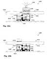
- FIGS. 20 a and 20 bare schematic diagrams representing an inductive power outlet 9201 protected by a local leak prevention system 9001 , according to another embodiment of the present disclosure.
- a primary coil 9221may be concealed behind a facing layer of a horizontal platform 9641 such as a desk-top, a kitchen work-top, a conference table or a work bench.
- a horizontal platform 9641such as a desk-top, a kitchen work-top, a conference table or a work bench.
- Such a platformmay be fabricated from a wide range of materials, including mica, Formica or wood veneer, for example.
- a primary coil 9221may be concealed beneath or emdedded within flooring materials and coverings such as rugs, fitted carpet, parquet, linoleum, floor tiles, tiling, paving and the like.
- the primary coil 9221may be embedded within or concealed behind a vertical surface such as a wall of a building or a cabinet, for example behind wallpaper or stretched canvas or the like.
- the primary coil 9221may be used to power an electrical device such as a computer 9262 wired to a secondary coil 9261 ; the computer 9262 being placed upon the platform 9641 such that the secondary coil 9261 coupled to the computer 9262 is aligned to the primary coil 9221 concealed within the platform 9641 .
- a primary detector 9421is located in the locality of the primary coil 9221 and is configured to detect a magnetic field 9222 generated by a primary coil 9221 actively transmitting power.
- the detector 9421may function in accordance with one or more of a variety of principles, including, inter alia, magnetic sensing means, Hall probes, etc.
- the detectormay be a heat sensor or electromagnetic sensor configured to detect one or more scientific effects inherent to or associated with the operation of the primary coil 9221 .
- a secondary detector 9441is also provided, to detect the presence or operation of the secondary coil 9261 .
- the secondary detector 9441may do this by detecting a signal from the secondary coil 9261 or by detecting a signal from the primary coil or from its surroundings that indicates directly or indirectly, the presence or absence of a secondary coil inductively coupled therewith.
- the secondary detectormay be a heat detector 9441 configured to detect a significant temperature rise in the platform 9641 in the vicinity of the primary coil 9221 .
- the secondary detectormay be a magnetic sensor, a Hall probe, an electromagnetic sensor, or the like, configured to detect transmissions from the secondary coil 9261 .
- the primary detector 9421may detect a magnetic field 9222 generated by the primary coil 9221 , and send a primary signal P to a controller 9401 indicating that power is being transmitted by the primary coil 9221 .
- the secondary detector 9441is a temperature probe, it detects no significant temperature rise and can be configured to send a secondary signal S to a controller 9401 indicating that an electric load is inductively coupled to the primary coil 9221 , or not to send a signal, thereby providing an equivalent indication, depending on the logic programming of the controller 9401 .
- the controller 9401receives a primary signal P, indicating that power is present in the primary coil 9221 , and a secondary signal S, indicating that an electric load is present, it does not trigger the circuit-breaker 9181 and the primary coil 9221 continues to draw power from the power supply 9141 .
- the controller 9161receives the primary signal P, indicating that power is being generated, and the secondary signal S, indicating that no electric load is present, consequently the controller 9161 triggers the circuit-breaker 9181 thereby disconnecting the primary coil 9221 from the power supply 9141 and preventing any further power from being transmitted by the primary coil 9221 .
- FIG. 21a schematic diagram is presented showing a plurality of inductive power outlets 9203 protected by a remote leak prevention system 9003 according to a further embodiment of the present disclosure.
- An array of primary inductive coils 9223are incorporated within a wall 9643 and wired to a power supply (not shown) via a driver 9233 .
- the primary coils 9223are arranged for inductively coupling with secondary coils 9263 wired to electrical devices, such as a light bulb 9262 , which are brought into proximity with them.
- the remote leak prevention system 9003includes a primary detector such as a radio receiver 9423 within range of the wall 9643 , tuned to detect radio waves at the characteristic frequency f. Such radio waves indicate that at least one primary coil 9223 is transmitting.
- the power outlet 9203may additionally include a secondary detector 9443 for detecting a secondary coil 9263 inductively coupled to a primary coil 9223 .
- the power transmissionmay then be modulated with a secondary tag indicating that a secondary coil 9263 is inductively coupled to the primary coil 9223 .
- the primary detector 9423may then demodulate the radio waves to identify the secondary tag. If no secondary tag is detected, the primary detector 9423 will communicate a control signal C to a controller 9500 indicating that power is being transmitted by at least one primary coil 9223 in the absence of a secondary coil 9263 . According to a basic embodiment, the controller 9500 is operable to then trigger a circuit breaker (not shown) thereby disconnecting all the primary coils 9223 .
- the driver 9233may additionally comprise a modulator (not shown) for tagging the power transmissions of each active primary coil 9223 a - i with a primary tag uniquely identifying the active primary coil 9223 a - i from which the radio waves are transmitted.
- the primary detector 9423will then detect the primary tag and thereby identify which rogue primary coil is transmitting power in the absence of a secondary coil.
- the primary detector 9423then communicates this to the controller 9500 which disconnects only the rogue primary coil.
- a method for preventing an inductive power outlet of embodiments of the disclosure from transmitting power in the absence of an electric load coupled thereto,is presented in the flow chart of FIG. 22 .
- the methodincludes the following steps:
Landscapes
- Engineering & Computer Science (AREA)
- Power Engineering (AREA)
- Computer Networks & Wireless Communication (AREA)
- Physics & Mathematics (AREA)
- Electromagnetism (AREA)
- Charge And Discharge Circuits For Batteries Or The Like (AREA)
- Details Of Connecting Devices For Male And Female Coupling (AREA)
Abstract
Description
- a ferromagnetic core for improving flux guidance between the primary inductor and the secondary inductor;
- at least one primary inductor being printed onto at least one paper sheet;
- the panel being water-resistant;
- the panel comprising a heating element;
- the panel comprising a high resistance primary inductor; and
- the primary inductor comprising an alloy having relatively high resistance such that oscillating currents therein, produce a heating effect.
- the paper sheet being a wallpaper;
- the primary inductor being adhered onto the back of a dielectric layer;
- the primary inductor comprising a conducting coil printed onto the paper; and
- the paper sheet comprising an adhesive layer for self adhering to the bounding surface.
- a first layer having an adhesive surface;
- a second layer comprising:
- at least one pair of electrical conductors electrically isolated from each other; and
- the at least one primary inductor being electrically coupled to the pair of electrical conductors; and
- a third layer overlaying the second layer such that the pair of electrical conductors and the primary inductor are sandwiched between the first layer and the second layer.
- the second layer comprising a two dimensional array of primary inductors;
- a release layer releasably engaged to the adhesive surface of the first layer;
- a coating applied to the outer face of the third layer, the adhesive surface releasably engaging with the coating when the power outlet tape is rolled upon itself;
- the tape comprising a scrim layer of interwoven fibers; and
- the tape comprising a ferromagnetic core for improving flux guidance between the primary inductor and the secondary inductor.
- the positioning mechanism comprising a carriage;
- the primary inductor being mounted upon at least one of the group comprising roller-balls, wheels, skis and levitating magnets;
- the primary inductor being affixed to at least one guiding cable;
- the positioning mechanism being motorized;
- the positioning mechanism being remotely controllable by a user;
- the primary inductor being affixed to a first magnetic element configured to be pulled by a second magnetic element;
- the positioning mechanism further comprising a clutch for engaging the primary coil to the back face of the bounding surface, and
- the positioning mechanism further comprising a release mechanism for disengaging the primary inductor from the back face of the bounding surface.
- the indicator being incorporated within the bounding surface;
- the indicator comprising a visual display representing a map of the surface, the location of the primary inductor being indicated upon the map;
- the indicator further comprising a control panel for adjusting the location of the primary inductor, the location of the primary inductor being indicated upon the control panel;
- the indicator comprising at least one transmitter configured to transmit a locator beam, the locator beam being detectable remotely;
- the location of the primary inductor being determinable by external sensors; and
- the location of the primary inductor being determinable by external sensors selected from the group comprising: proximity sensors, volume sensors, infra-red sensors, ultrasonic sensors, magnetic sensors, Hall probes, inductance sensors and capacitance sensors.
- the emitter being incorporated within the primary inductor and the radiation being selected such that the substantially opaque surface translucent to the radiation;
- the emitter comprising a light emitting diode;
- the emitter comprising the primary inductor;
- the radiation being detectable by a photodiode;
- the radiation comprising at least one of the group comprising: electromagnetic radiation, sound waves and ultrasonic waves;
- the radiation comprising infra-red radiation; the infra red radiation being detectable by a digital camera; and
- the location of the primary inductor being encoded into a location signal and the location signal being transmitted by the radiation.
- Step (a)—the primary inductor transmitting power;
- Step (b)—detecting that the primary inductor is transmitting power;
- Step (c)—checking that the primary inductor is inductively coupled to the secondary inductor; and
- Step (d)—disconnecting the primary inductor from the power supply if no secondary inductor is detected.
- communicating a signal from the primary inductor to a controller; and
- detecting a radiation emanating from the primary inductor.
- communicating a signal from the secondary inductor to a controller;
- encoding a secondary signal within radiation emanating from the primary inductor; and
- monitoring the temperature in the vicinity of the primary inductor and checking for a significant rise in the temperature.
- a) a primary coil transmits power;
- b) the power transmission from the primary coil is detected
- c) a secondary detector searches for a secondary coil inductively coupled to the primary coil; and
- d) the primary coil is disconnected from its power supply if no secondary coil is detected.
Claims (16)
Priority Applications (1)
| Application Number | Priority Date | Filing Date | Title |
|---|---|---|---|
| US12/757,286US8283812B2 (en) | 2007-10-09 | 2010-04-09 | Inductive power providing system having moving outlets |
Applications Claiming Priority (11)
| Application Number | Priority Date | Filing Date | Title |
|---|---|---|---|
| US96063607P | 2007-10-09 | 2007-10-09 | |
| US110607P | 2007-10-31 | 2007-10-31 | |
| US99646007P | 2007-11-19 | 2007-11-19 | |
| US99659207P | 2007-11-27 | 2007-11-27 | |
| US99692207P | 2007-12-11 | 2007-12-11 | |
| US603707P | 2007-12-17 | 2007-12-17 | |
| US831907P | 2007-12-20 | 2007-12-20 | |
| US613207P | 2007-12-26 | 2007-12-26 | |
| US623808P | 2008-01-02 | 2008-01-02 | |
| PCT/IL2008/001347WO2009047768A2 (en) | 2007-10-09 | 2008-10-12 | Inductive power providing system |
| US12/757,286US8283812B2 (en) | 2007-10-09 | 2010-04-09 | Inductive power providing system having moving outlets |
Related Parent Applications (1)
| Application Number | Title | Priority Date | Filing Date |
|---|---|---|---|
| PCT/IL2008/001347ContinuationWO2009047768A2 (en) | 2007-10-09 | 2008-10-12 | Inductive power providing system |
Publications (2)
| Publication Number | Publication Date |
|---|---|
| US20100244584A1 US20100244584A1 (en) | 2010-09-30 |
| US8283812B2true US8283812B2 (en) | 2012-10-09 |
Family
ID=42666569
Family Applications (4)
| Application Number | Title | Priority Date | Filing Date |
|---|---|---|---|
| US12/757,277AbandonedUS20100219183A1 (en) | 2007-11-19 | 2010-04-09 | System for inductive power provision within a bounding surface |
| US12/757,476Active2030-06-28US8624750B2 (en) | 2007-10-09 | 2010-04-09 | System and method for inductive power provision over an extended surface |
| US12/757,286ActiveUS8283812B2 (en) | 2007-10-09 | 2010-04-09 | Inductive power providing system having moving outlets |
| US14/097,886AbandonedUS20140091638A1 (en) | 2007-10-09 | 2013-12-05 | System and method for inductive power provision over an extended surface |
Family Applications Before (2)
| Application Number | Title | Priority Date | Filing Date |
|---|---|---|---|
| US12/757,277AbandonedUS20100219183A1 (en) | 2007-11-19 | 2010-04-09 | System for inductive power provision within a bounding surface |
| US12/757,476Active2030-06-28US8624750B2 (en) | 2007-10-09 | 2010-04-09 | System and method for inductive power provision over an extended surface |
Family Applications After (1)
| Application Number | Title | Priority Date | Filing Date |
|---|---|---|---|
| US14/097,886AbandonedUS20140091638A1 (en) | 2007-10-09 | 2013-12-05 | System and method for inductive power provision over an extended surface |
Country Status (1)
| Country | Link |
|---|---|
| US (4) | US20100219183A1 (en) |
Cited By (38)
| Publication number | Priority date | Publication date | Assignee | Title |
|---|---|---|---|---|
| US20120091820A1 (en)* | 2008-09-27 | 2012-04-19 | Campanella Andrew J | Wireless power transfer within a circuit breaker |
| US20130119777A1 (en)* | 2011-11-03 | 2013-05-16 | Shaw Industries Group | Wireless energy transfer systems |
| US20130169222A1 (en)* | 2011-12-30 | 2013-07-04 | Samsung Electro-Mechanics Co., Ltd. | Multi wireless charging apparatus and method for manufacturing the same |
| US20140247007A1 (en)* | 2013-03-01 | 2014-09-04 | Luxx Lighting Technology (Taiwan) Ltd. | Inductive Power Transfer System and Transmitting and Receiving Devices Thereof |
| US20150069965A1 (en)* | 2013-09-12 | 2015-03-12 | E I Du Pont De Nemours And Company | Embeddable wireless charger |
| US9438070B2 (en) | 2013-09-30 | 2016-09-06 | Norman R. Byrne | Articles with electrical charging surfaces |
| US9484751B2 (en) | 2013-09-30 | 2016-11-01 | Norman R. Byrne | Wireless power for portable articles |
| US9543780B2 (en) | 2013-06-18 | 2017-01-10 | Alvin Felix Ho | Modular wireless charging station and assembly |
| US9793739B2 (en) | 2013-08-07 | 2017-10-17 | Sandisk Technologies Llc | Wireless power transmitting device |
| USD811756S1 (en) | 2016-12-19 | 2018-03-06 | Kimball International, Inc. | Lounge end |
| USD811759S1 (en) | 2016-12-19 | 2018-03-06 | Kimball International, Inc. | Furniture spine unit with bistro table |
| USD811760S1 (en) | 2016-12-19 | 2018-03-06 | Kimball International, Inc. | Furniture spine unit with work surface |
| US9923350B1 (en) | 2016-10-11 | 2018-03-20 | Michael Hunt | System and apparatus for providing functional and decorative electrical cover plates |
| USD812949S1 (en) | 2016-12-19 | 2018-03-20 | Kimball International, Inc. | 120 degree furniture spine unit |
| US20180259257A1 (en)* | 2017-03-08 | 2018-09-13 | Lg Electronics Inc. | Washstand furniture |
| CN108567360A (en)* | 2017-03-08 | 2018-09-25 | Lg电子株式会社 | Cabinet under washstand |
| US10181735B2 (en) | 2015-03-11 | 2019-01-15 | Norman R. Byrne | Portable electrical power unit |
| USD839034S1 (en) | 2016-12-19 | 2019-01-29 | Kimball International, Inc. | Furniture spine unit |
| USD839033S1 (en) | 2016-06-06 | 2019-01-29 | Kimball International, Inc. | Conference table |
| US20190101255A1 (en)* | 2017-10-04 | 2019-04-04 | Resilience Magnum IP, LLC | Lighting drywall |
| US20190261521A1 (en)* | 2017-02-02 | 2019-08-22 | Japan Display Inc. | Display device |
| US10408988B2 (en) | 2017-10-04 | 2019-09-10 | Resilience Magnum IP, LLC | Techniques for enhanced diffusion lighting |
| US10510251B2 (en) | 2017-10-04 | 2019-12-17 | Resilience Magnum IP, LLC | Parking space light |
| US10547188B2 (en) | 2016-03-11 | 2020-01-28 | Norman R. Byrne | Furniture-mounted charging station |
| US10574757B2 (en) | 2017-10-04 | 2020-02-25 | Resilience Magnum IP, LLC | Self aware lights that self-configure |
| US10591211B2 (en) | 2017-03-08 | 2020-03-17 | Lg Electronics Inc. | Washstand furniture |
| US10631380B2 (en) | 2017-10-04 | 2020-04-21 | Resilience Magnum IP, LLC | Information and hub lights |
| US10663225B2 (en) | 2017-03-08 | 2020-05-26 | Lg Electronics Inc. | Washstand furniture |
| US10677527B2 (en) | 2017-03-08 | 2020-06-09 | Lg Electronics Inc. | Washstand furniture |
| US10680392B2 (en) | 2017-07-24 | 2020-06-09 | Norman R. Byrne | Furniture-mounted electrical charging station |
| US10677526B2 (en) | 2017-03-08 | 2020-06-09 | Lg Electronics Inc. | Washstand furniture |
| US10718566B2 (en) | 2017-03-08 | 2020-07-21 | Lg Electronics Inc. | Washstand furniture |
| US10794603B2 (en) | 2017-10-04 | 2020-10-06 | Resilience Magnum IP, LLC | Intelligent purifier light |
| US10867486B2 (en) | 2017-10-04 | 2020-12-15 | Resilience Magnum IP, LLC | Hospitality light |
| US10988940B2 (en) | 2016-06-03 | 2021-04-27 | Norman R. Byrne | Surface-mounted resonators for wireless power |
| US11244563B2 (en) | 2017-10-04 | 2022-02-08 | Resilience Magnum IP, LLC | Flow management light |
| US11331822B2 (en) | 2014-04-30 | 2022-05-17 | Jeam Roman | Wirelessly charging hair clipper |
| US11596118B2 (en) | 2017-10-04 | 2023-03-07 | Resilience Magnum IP, LLC | Intelligent horticulture light |
Families Citing this family (123)
| Publication number | Priority date | Publication date | Assignee | Title |
|---|---|---|---|---|
| US11201500B2 (en) | 2006-01-31 | 2021-12-14 | Mojo Mobility, Inc. | Efficiencies and flexibilities in inductive (wireless) charging |
| US8169185B2 (en) | 2006-01-31 | 2012-05-01 | Mojo Mobility, Inc. | System and method for inductive charging of portable devices |
| US7952322B2 (en)* | 2006-01-31 | 2011-05-31 | Mojo Mobility, Inc. | Inductive power source and charging system |
| US7948208B2 (en) | 2006-06-01 | 2011-05-24 | Mojo Mobility, Inc. | Power source, charging system, and inductive receiver for mobile devices |
| US11329511B2 (en) | 2006-06-01 | 2022-05-10 | Mojo Mobility Inc. | Power source, charging system, and inductive receiver for mobile devices |
| CN101802942A (en) | 2007-01-29 | 2010-08-11 | 普迈公司 | Pinless power coupling |
| CN101377983B (en)* | 2007-08-29 | 2012-03-14 | 博西华电器(江苏)有限公司 | Household appliance operation apparatus and indication unit operation method |
| US8819743B2 (en) | 2007-12-19 | 2014-08-26 | Dish Network L.L.C. | Transfer of data related to broadcast programming over a communication network |
| CN102084442B (en) | 2008-03-17 | 2013-12-04 | 鲍尔马特技术有限公司 | Inductive transmission system |
| US9960642B2 (en) | 2008-03-17 | 2018-05-01 | Powermat Technologies Ltd. | Embedded interface for wireless power transfer to electrical devices |
| US20110050164A1 (en) | 2008-05-07 | 2011-03-03 | Afshin Partovi | System and methods for inductive charging, and improvements and uses thereof |
| US8780008B2 (en)* | 2008-06-20 | 2014-07-15 | Dish Network L.L.C. | Reinforced mount for an antenna assembly |
| US9337545B2 (en) | 2008-06-20 | 2016-05-10 | Dish Network L.L.C. | Apparatus and systems for mounting an electrical switching device |
| US8907862B2 (en) | 2011-04-12 | 2014-12-09 | Dish Network L.L.C. | Apparatus and systems for mounting an electrical switching device |
| US8981598B2 (en) | 2008-07-02 | 2015-03-17 | Powermat Technologies Ltd. | Energy efficient inductive power transmission system and method |
| US11979201B2 (en) | 2008-07-02 | 2024-05-07 | Powermat Technologies Ltd. | System and method for coded communication signals regulating inductive power transmissions |
| WO2010132578A1 (en) | 2009-05-12 | 2010-11-18 | Kimball International, Inc. | Furniture with wireless power |
| US9124308B2 (en) | 2009-05-12 | 2015-09-01 | Kimball International, Inc. | Furniture with wireless power |
| WO2011070637A1 (en)* | 2009-12-07 | 2011-06-16 | 富士通株式会社 | Magnetic-field resonance power transmission device and magnetic-field resonance power receiving device |
| EP2519424A2 (en)* | 2009-12-28 | 2012-11-07 | Toyoda Gosei Co., Ltd. | Recharging or connection tray for portable electronic devices |
| US8462075B2 (en) | 2010-02-23 | 2013-06-11 | Dish Network L.L.C. | Apparatus for mounting an object to a railing |
| JP5478326B2 (en) | 2010-03-30 | 2014-04-23 | パナソニック株式会社 | Contactless power supply system |
| WO2011156768A2 (en) | 2010-06-11 | 2011-12-15 | Mojo Mobility, Inc. | System for wireless power transfer that supports interoperability, and multi-pole magnets for use therewith |
| US8528227B2 (en)* | 2010-07-26 | 2013-09-10 | General Electric Company | Apparatus and method for refrigerant cycle capacity acceleration |
| US8601717B2 (en) | 2010-07-26 | 2013-12-10 | General Electric Company | Apparatus and method for refrigeration cycle capacity enhancement |
| US8353114B2 (en) | 2010-07-26 | 2013-01-15 | General Electric Company | Apparatus and method for refrigeration cycle with auxiliary heating |
| CN103154413B (en)* | 2010-10-04 | 2015-07-22 | 灌木塑料科技有限公司 | Method and device for contactless transmission of electrical energy and/or electrical signals between a wall and a leaf fixed to the wall |
| US8994325B2 (en)* | 2010-11-17 | 2015-03-31 | Boston Scientific Neuromodulation Corporation | External charger for an implantable medical device having at least one moveable charging coil |
| US8646186B2 (en) | 2010-12-16 | 2014-02-11 | Dish Network L.L.C. | Multi-angle levels and plumbing methods |
| WO2012093398A2 (en) | 2011-01-05 | 2012-07-12 | Powermat Technologies Ltd. | System and method for integrating inductive power functionality into furniture |
| US9166440B2 (en) | 2011-01-10 | 2015-10-20 | Powermat Technologies Ltd. | System for transferring power inductively to items within a container |
| US9178369B2 (en) | 2011-01-18 | 2015-11-03 | Mojo Mobility, Inc. | Systems and methods for providing positioning freedom, and support of different voltages, protocols, and power levels in a wireless power system |
| US11342777B2 (en) | 2011-01-18 | 2022-05-24 | Mojo Mobility, Inc. | Powering and/or charging with more than one protocol |
| US10115520B2 (en) | 2011-01-18 | 2018-10-30 | Mojo Mobility, Inc. | Systems and method for wireless power transfer |
| US9496732B2 (en) | 2011-01-18 | 2016-11-15 | Mojo Mobility, Inc. | Systems and methods for wireless power transfer |
| JP5847161B2 (en)* | 2011-03-31 | 2016-01-20 | 積水化学工業株式会社 | Building and its construction method |
| US8553408B2 (en) | 2011-09-06 | 2013-10-08 | Dana Innovations | Charging docking system |
| US8802985B2 (en) | 2011-09-07 | 2014-08-12 | Dish Network L.L.C. | In-wall extension apparatus |
| KR101305579B1 (en)* | 2011-09-09 | 2013-09-09 | 엘지이노텍 주식회사 | Wireless power relay apparatus and wireless power transmission system |
| US8847436B2 (en)* | 2011-09-12 | 2014-09-30 | Lighting Science Group Corporation | System for inductively powering an electrical device and associated methods |
| JP5906456B2 (en) | 2011-09-15 | 2016-04-20 | パナソニックIpマネジメント株式会社 | Contactless power supply system and repeater |
| JP2013070477A (en)* | 2011-09-21 | 2013-04-18 | Panasonic Corp | Non-contact power supply system |
| JP5646425B2 (en)* | 2011-09-28 | 2014-12-24 | 株式会社東芝 | Electronics |
| WO2013048261A1 (en)* | 2011-09-29 | 2013-04-04 | Powerbyproxi Limited | Wirelessly rechargeable battery and components thereof |
| EP2765681B1 (en)* | 2011-10-07 | 2019-03-13 | Toyota Jidosha Kabushiki Kaisha | Power reception device, vehicle provided with same, and power transmission system |
| KR101262556B1 (en)* | 2011-10-14 | 2013-05-08 | 엘지이노텍 주식회사 | Wireless power transmission apparatus |
| DE102011054541A1 (en)* | 2011-10-17 | 2013-04-18 | Conductix-Wampfler Gmbh | Device for inductive transmission of electrical energy |
| DE102011118564A1 (en)* | 2011-11-15 | 2013-05-16 | Grossenbacher System Ag | Contactless power supply and signal transmission through cladding element for building parts |
| CN103348561B (en)* | 2011-12-14 | 2017-07-07 | 松下知识产权经营株式会社 | information transmission system |
| US9620282B2 (en) | 2011-12-14 | 2017-04-11 | Panasonic Intellectual Property Management Co., Ltd. | Noncontact connector apparatus and system using inductive coupling between coils |
| JP5817500B2 (en)* | 2011-12-16 | 2015-11-18 | 株式会社Ihi | Power feeding system and non-contact power feeding method |
| EP2621050B1 (en)* | 2012-01-27 | 2015-04-08 | Braun GmbH | Inductive Charger for Hand-Held Appliances |
| US9722447B2 (en) | 2012-03-21 | 2017-08-01 | Mojo Mobility, Inc. | System and method for charging or powering devices, such as robots, electric vehicles, or other mobile devices or equipment |
| US20130271069A1 (en) | 2012-03-21 | 2013-10-17 | Mojo Mobility, Inc. | Systems and methods for wireless power transfer |
| US11502551B2 (en) | 2012-07-06 | 2022-11-15 | Energous Corporation | Wirelessly charging multiple wireless-power receivers using different subsets of an antenna array to focus energy at different locations |
| US20140021798A1 (en)* | 2012-07-17 | 2014-01-23 | Witricity Corporation | Wireless energy transfer with repeater resonators |
| US9123987B2 (en) | 2012-07-31 | 2015-09-01 | Dish Network L.L.C. | Antenna mounting systems and methods |
| JP5914879B2 (en) | 2012-10-31 | 2016-05-11 | パナソニックIpマネジメント株式会社 | Non-contact power supply system, movable device, and control method for power supply device of non-contact power supply system |
| TWM457910U (en)* | 2013-01-25 | 2013-07-21 | Ceramate Technical Co Ltd | Multi-directional wireless power supply device using arc coil coupling power |
| WO2014147736A1 (en) | 2013-03-19 | 2014-09-25 | パイオニア株式会社 | Power transmission device |
| US9837846B2 (en) | 2013-04-12 | 2017-12-05 | Mojo Mobility, Inc. | System and method for powering or charging receivers or devices having small surface areas or volumes |
| WO2015017671A2 (en)* | 2013-08-01 | 2015-02-05 | Urbaneer LLC | Apparatus and method for reconfigurable space |
| WO2015062947A1 (en)* | 2013-10-30 | 2015-05-07 | Koninklijke Philips N.V. | Thermal barrier for wireless power transfer |
| US9342710B2 (en)* | 2013-11-21 | 2016-05-17 | Nxp B.V. | Electronic tamper detection |
| TWI539711B (en)* | 2014-01-02 | 2016-06-21 | 鴻騰精密科技股份有限公司 | Wireless charging module |
| US9780573B2 (en)* | 2014-02-03 | 2017-10-03 | Witricity Corporation | Wirelessly charged battery system |
| US9300151B2 (en)* | 2014-02-25 | 2016-03-29 | Youhua Technology (Shenzhen) Co., Ltd. | Wireless charging device |
| AT515624A1 (en)* | 2014-03-31 | 2015-10-15 | Kny Design Gmbh | System for wireless energy transmission |
| US9735608B2 (en)* | 2014-04-02 | 2017-08-15 | Jabil Inc. | Contact point power pad for battery charger |
| US9805864B2 (en)* | 2014-04-04 | 2017-10-31 | Apple Inc. | Inductive spring system |
| CN103984264A (en)* | 2014-05-19 | 2014-08-13 | 苏州乐聚一堂电子科技有限公司 | Wireless induction button |
| WO2015196296A1 (en)* | 2014-06-25 | 2015-12-30 | Elix Wireless Charging Systems Inc. | Methods and apparatus for automatic alignment of wireless power transfer systems |
| US10454307B2 (en)* | 2014-08-04 | 2019-10-22 | Jabil Inc. | Wireless power apparatus, system and method |
| US10283996B2 (en)* | 2014-09-03 | 2019-05-07 | Apple Inc. | Packaging for an electronic device |
| CN104578240A (en)* | 2014-10-18 | 2015-04-29 | 刘跃进 | Automatic-focusing wireless charging belt system and full-automatic laying device for wireless charging belt |
| WO2016110790A1 (en)* | 2015-01-08 | 2016-07-14 | Ferrari Bk S.R.L. | Modular device for wireless transmission of electrical power |
| US10559971B2 (en) | 2015-04-10 | 2020-02-11 | Ossia Inc. | Wirelessly chargeable battery apparatus |
| EP3091528B1 (en)* | 2015-05-05 | 2020-10-07 | Harman Professional Denmark ApS | Support frame for video wall |
| DE102015218437A1 (en)* | 2015-09-25 | 2017-03-30 | Bayerische Motoren Werke Aktiengesellschaft | Method for producing an induction coil |
| US10038332B1 (en) | 2015-12-24 | 2018-07-31 | Energous Corporation | Systems and methods of wireless power charging through multiple receiving devices |
| ES1151333Y (en)* | 2016-01-26 | 2016-10-27 | Larburu Santos Francisco Laserna | Inductive table |
| NL2016241B1 (en)* | 2016-02-09 | 2017-08-15 | Trespa Int Bv | A decorative panel |
| US10377469B2 (en)* | 2016-03-04 | 2019-08-13 | The Boeing Company | Non-contact power supply and data transfer on aerial vehicles |
| DE112016006712T5 (en)* | 2016-04-06 | 2018-12-20 | Mitsubishi Electric Corporation | Heating cooker system, and cooking device |
| EP3494645A1 (en)* | 2016-08-05 | 2019-06-12 | Pilkington Group Limited | Laminated glazing |
| US10622820B2 (en) | 2016-09-23 | 2020-04-14 | Apple Inc. | Bobbin structure and transmitter coil for wireless charging mats |
| CN106340971A (en)* | 2016-09-23 | 2017-01-18 | 欣百达装饰工程有限公司 | Movable wireless power supply system for exhibition hall |
| US10113360B2 (en)* | 2016-12-09 | 2018-10-30 | Hall Labs Llc | Roll-up wall tensioning |
| CN108270298B (en)* | 2017-01-04 | 2022-12-02 | 中兴通讯股份有限公司 | Charging method and device |
| US11146093B2 (en) | 2017-03-31 | 2021-10-12 | Ossia Inc. | Actively modifying output voltage of a wirelessly chargeable energy storage apparatus |
| US12074460B2 (en) | 2017-05-16 | 2024-08-27 | Wireless Electrical Grid Lan, Wigl Inc. | Rechargeable wireless power bank and method of using |
| US11462949B2 (en) | 2017-05-16 | 2022-10-04 | Wireless electrical Grid LAN, WiGL Inc | Wireless charging method and system |
| US12074452B2 (en) | 2017-05-16 | 2024-08-27 | Wireless Electrical Grid Lan, Wigl Inc. | Networked wireless charging system |
| US10283952B2 (en) | 2017-06-22 | 2019-05-07 | Bretford Manufacturing, Inc. | Rapidly deployable floor power system |
| US10714985B2 (en) | 2017-10-11 | 2020-07-14 | Spark Connected LLC | Wireless power transfer system and method |
| US10610068B2 (en) | 2018-01-06 | 2020-04-07 | Kohler Co. | Toilet seat and hinge |
| WO2019173022A1 (en)* | 2018-03-04 | 2019-09-12 | David Simpson | Induction driven lighting |
| US11996229B2 (en) | 2018-03-07 | 2024-05-28 | University Of Tennessee Research Foundation | Series self-resonant coil structure for conducting wireless power transfer |
| JP6687294B1 (en)* | 2018-08-21 | 2020-04-22 | 三菱電機株式会社 | Non-contact power feeding power transmission control device, non-contact power feeding power transmission control method, non-contact power feeding power transmitting device, and non-contact power feeding system |
| US11056870B2 (en) | 2018-09-20 | 2021-07-06 | United States Gypsum Company | Magnetic decorative trim with DC power transmission |
| US11444485B2 (en) | 2019-02-05 | 2022-09-13 | Mojo Mobility, Inc. | Inductive charging system with charging electronics physically separated from charging coil |
| EP3921945A1 (en) | 2019-02-06 | 2021-12-15 | Energous Corporation | Systems and methods of estimating optimal phases to use for individual antennas in an antenna array |
| EP3921917A4 (en)* | 2019-02-07 | 2022-12-14 | Powermat Technologies Ltd. | Wireless power transmission system |
| US11509169B2 (en) | 2019-02-13 | 2022-11-22 | Spark Connected LLC | Sub-surface wireless charging |
| EP3935712A4 (en) | 2019-03-07 | 2022-12-14 | Hubbell Incorporated | Inductive power transfer |
| US11152823B2 (en) | 2019-04-01 | 2021-10-19 | Spark Connected LLC | Translation unit for wireless power transfer |
| DE102019211399A1 (en) | 2019-07-31 | 2021-02-04 | Würth Elektronik eiSos Gmbh & Co. KG | Coil arrangement and device for wireless electromagnetic energy transmission |
| US11159056B2 (en) | 2019-09-12 | 2021-10-26 | Spark Connected LLC | Wireless power receiver circuit and method |
| DE102020100075A1 (en)* | 2020-01-03 | 2021-07-08 | PUK Group GmbH & Co. KG | Supply device, energy supply system and method for electrical energy supply |
| US11515739B2 (en) | 2020-02-14 | 2022-11-29 | Spark Connected LLC | FOD and wireless power transfer calibration |
| US12046910B2 (en) | 2020-02-24 | 2024-07-23 | Ossia Inc. | Devices and systems for providing wirelessly chargeable batteries with improved charge capacities |
| US12068631B2 (en) | 2020-04-13 | 2024-08-20 | Spark Connected LLC | Alignment method for sub-surface wireless charger |
| US12053055B2 (en) | 2020-05-15 | 2024-08-06 | Spark Connected LLC | Dual function wireless power and thermal receiver |
| US11888331B2 (en) | 2020-07-01 | 2024-01-30 | Spark Connected LLC | Sub-surface wireless charging and associated method |
| US10892653B1 (en)* | 2020-07-29 | 2021-01-12 | Eric Rolfe | System and method for simultaneous inductive recharging of multiple electronic devices |
| DE102020121774A1 (en) | 2020-08-19 | 2022-02-24 | Eppendorf Ag | Loading device for an electronic dosing device and electronic dosing device |
| US11855463B2 (en) | 2020-12-04 | 2023-12-26 | Spark Connected LLC | Wireless power transmission to a mobile device |
| EP4109692A1 (en) | 2021-06-24 | 2022-12-28 | Sensonic Design Zrt. | System and method for positioning a movable electrical socket |
| WO2023014951A2 (en)* | 2021-08-06 | 2023-02-09 | Ruben Murray | Electronic fry pan and battery power supply |
| WO2023016656A1 (en)* | 2021-08-13 | 2023-02-16 | Daw Se | Surface function system, use of the surface function system, building wall, and acoustic element |
| US12241912B2 (en) | 2021-10-22 | 2025-03-04 | Raytheon Company | Socketless or flush mount QFN (quad flat no lead) test board, fixture, and method |
| US12191650B2 (en) | 2022-06-07 | 2025-01-07 | Smart Volt, Llc | Low voltage in-wall power system for motorized shades |
| US20240159427A1 (en)* | 2022-11-11 | 2024-05-16 | Rheem Manufacturing Company | Systems and methods for powering water heating devices using wireless power transmissions |
Citations (138)
| Publication number | Priority date | Publication date | Assignee | Title |
|---|---|---|---|---|
| US3771085A (en) | 1971-08-10 | 1973-11-06 | Tokyo Keiki Kk | Deviation detecting apparatus |
| US3938018A (en) | 1974-09-16 | 1976-02-10 | Dahl Ernest A | Induction charging system |
| US4160193A (en) | 1977-11-17 | 1979-07-03 | Richmond Abraham W | Metal vapor electric discharge lamp system |
| US4431948A (en) | 1982-08-09 | 1984-02-14 | Standun Controls, Inc. | Apparatus for control of load power consumption |
| EP0160990A2 (en) | 1984-05-11 | 1985-11-13 | Telefunken Systemtechnik Gmbh | Inductive transmission of power and data |
| US4754180A (en) | 1985-04-01 | 1988-06-28 | Honeywell Inc. | Forceless non-contacting power transformer |
| US4977515A (en) | 1988-08-29 | 1990-12-11 | Rudden Frank G | Load management device and method of use |
| US5221877A (en) | 1992-03-10 | 1993-06-22 | Davis Controls Corporation | Power reduction control for inductive lighting installation |
| EP0558316A1 (en) | 1992-02-27 | 1993-09-01 | G2 Design Limited | An inductive loop power transmission system |
| US5278771A (en) | 1991-07-12 | 1994-01-11 | Seti Corporation | Programmable timed electrical power management device |
| US5367242A (en) | 1991-09-20 | 1994-11-22 | Ericsson Radio Systems B.V. | System for charging a rechargeable battery of a portable unit in a rack |
| US5455466A (en) | 1993-07-29 | 1995-10-03 | Dell Usa, L.P. | Inductive coupling system for power and data transfer |
| US5486394A (en) | 1994-08-26 | 1996-01-23 | E-Z Taping System, Inc. | Self-release self-adhesive drywall tape |
| WO1996002879A1 (en) | 1994-07-19 | 1996-02-01 | Elonex Technologies, Inc. | Micro personal digital assistant |
| US5528113A (en) | 1993-10-21 | 1996-06-18 | Boys; John T. | Inductive power pick-up coils |
| US5550452A (en) | 1993-07-26 | 1996-08-27 | Nintendo Co., Ltd. | Induction charging apparatus |
| US5600225A (en) | 1994-06-30 | 1997-02-04 | Nippon Electric Co | Noncontacting charging device |
| US5713939A (en) | 1996-09-16 | 1998-02-03 | Sulzer Intermedics Inc. | Data communication system for control of transcutaneous energy transmission to an implantable medical device |
| US5734254A (en) | 1996-12-06 | 1998-03-31 | Hewlett-Packard Company | Battery pack and charging system for a portable electronic device |
| US5762250A (en) | 1994-07-06 | 1998-06-09 | Truckin' Movers Corporation | Convertible carrying case and work platform for small electronic devices |
| US5821731A (en) | 1996-01-30 | 1998-10-13 | Sumitomo Wiring Systems, Ltd. | Connection system and connection method for an electric automotive vehicle |
| US5821728A (en) | 1996-07-22 | 1998-10-13 | Schwind; John P. | Armature induction charging of moving electric vehicle batteries |
| US5907285A (en) | 1993-12-09 | 1999-05-25 | Steelcase Inc. | Furniture unit having a modular communication network |
| US5929598A (en) | 1996-07-03 | 1999-07-27 | Uniden Corporation | Noncontact charging device, charger, cordless electric equipment, and noncontact charger |
| US5949214A (en) | 1997-11-04 | 1999-09-07 | Input/Output, Inc. | Rechargeable battery pack |
| US6042005A (en) | 1997-06-20 | 2000-03-28 | Basile; Mark R. | Personal identification and promotional system using personal and medical information |
| US6211649B1 (en) | 1999-03-25 | 2001-04-03 | Sourcenext Corporation | USB cable and method for charging battery of external apparatus by using USB cable |
| US6230029B1 (en) | 1998-01-07 | 2001-05-08 | Advanced Mobile Solutions, Inc. | Modular wireless headset system |
| WO2002001557A1 (en) | 2000-06-27 | 2002-01-03 | Citizen Watch Co., Ltd. | Disk drive |
| WO2002015320A1 (en) | 2000-08-16 | 2002-02-21 | Inca Systems Co., Ltd. | Battery charging system and battery charging apparatus thereof |
| US20020057584A1 (en) | 2000-11-14 | 2002-05-16 | Salcomp Oy | Power supply arrangement and inductively coupled battery charger with wirelessly coupled control, and method for wirelessly controlling a power supply arrangement and an inductively coupled battery charger |
| US6396935B1 (en) | 1996-01-26 | 2002-05-28 | Veijo Sakari Makkonen | Headset and method for a headset |
| US6436299B1 (en) | 1999-06-21 | 2002-08-20 | Amway Corporation | Water treatment system with an inductively coupled ballast |
| US6441589B1 (en) | 2001-04-02 | 2002-08-27 | Bellsouth Intellectual Property Corporation | Portable battery recharge station |
| US20020158512A1 (en) | 2001-04-26 | 2002-10-31 | Satoshi Mizutani | Mounting structure including communication system for transmitting multiplex control signal to vehicle electrical devices |
| US6484260B1 (en) | 1998-04-24 | 2002-11-19 | Identix, Inc. | Personal identification system |
| US6532298B1 (en) | 1998-11-25 | 2003-03-11 | Iridian Technologies, Inc. | Portable authentication device and method using iris patterns |
| US6586909B1 (en) | 2001-12-21 | 2003-07-01 | Ron Trepka | Parallel battery charging device |
| US6644557B1 (en) | 2002-03-25 | 2003-11-11 | Robert A Jacobs | Access controlled thermostat system |
| US20030210106A1 (en) | 2002-05-13 | 2003-11-13 | Splashpower Limited, A Company Incorporated In The Uk | Contact-less power transfer |
| US6673250B2 (en) | 1999-06-21 | 2004-01-06 | Access Business Group International Llc | Radio frequency identification system for a fluid treatment system |
| US20040023633A1 (en) | 2002-07-31 | 2004-02-05 | Gordon Mark A. | Handheld wireless device holder |
| US6721540B1 (en) | 1999-03-19 | 2004-04-13 | Seiko Epson Corporation | Electronic device |
| US6731071B2 (en) | 1999-06-21 | 2004-05-04 | Access Business Group International Llc | Inductively powered lamp assembly |
| US6766040B1 (en) | 2000-10-02 | 2004-07-20 | Biometric Solutions, Llc | System and method for capturing, enrolling and verifying a fingerprint |
| GB2399466A (en) | 2003-03-10 | 2004-09-15 | Univ City Hong Kong | Battery charging system |
| US20040195767A1 (en) | 2002-12-10 | 2004-10-07 | Mitch Randall | Systems and methods for providing electric power to mobile and arbitrarily positioned devices |
| US20040203537A1 (en) | 2003-04-14 | 2004-10-14 | Shikio Yoshida | Wireless transmission module |
| US6825620B2 (en) | 1999-06-21 | 2004-11-30 | Access Business Group International Llc | Inductively coupled ballast circuit |
| US20040242264A1 (en) | 2003-01-09 | 2004-12-02 | Samsung Electronics Co., Ltd. | Communication device and wireless headset apparatus |
| US20040261802A1 (en) | 2003-06-30 | 2004-12-30 | Griffin William T. | Stand for electrically heated cigarette smoking device |
| US20050007067A1 (en) | 1999-06-21 | 2005-01-13 | Baarman David W. | Vehicle interface |
| US6870475B2 (en)* | 2002-07-08 | 2005-03-22 | Draeger Medical Systems Inc. | Electrically isolated power and data coupling system suitable for portable and other equipment |
| US20050083020A1 (en) | 2003-10-20 | 2005-04-21 | Baarman David W. | Electrostatic charge storage assembly |
| US6888438B2 (en) | 2001-06-15 | 2005-05-03 | City University Of Hong Kong | Planar printed circuit-board transformers with effective electromagnetic interference (EMI) shielding |
| US6894457B2 (en) | 2002-11-01 | 2005-05-17 | American Power Conversion Corporation | Universal multiple device power adapter and carry case |
| US20050130593A1 (en) | 2003-12-16 | 2005-06-16 | Michalak Gerald P. | Integrated wireless headset |
| US20050169506A1 (en) | 2004-01-07 | 2005-08-04 | Identification International, Inc. | Low power fingerprint capture system, apparatus, and method |
| US20050192062A1 (en) | 2002-09-18 | 2005-09-01 | Mickle Marlin H. | Recharging method and apparatus |
| US20050233768A1 (en) | 2004-04-16 | 2005-10-20 | Hon Hai Precision Industry Co., Ltd. | Wireless transmitter and earphone based on 802.11a/b/g standard |
| US20060028176A1 (en) | 2004-07-22 | 2006-02-09 | Qingfeng Tang | Cellular telephone battery recharging apparatus |
| WO2006015143A2 (en) | 2004-07-28 | 2006-02-09 | Newton Peripherals, Llc | Peripheral devices for portable computer |
| US20060043927A1 (en) | 2002-09-27 | 2006-03-02 | Splashpower Limited | Retention of rechargeable devices |
| US20060052144A1 (en) | 2004-09-08 | 2006-03-09 | Seil Oliver D | Holder, electrical supply, and RF transmitter unit for electronic devices |
| US20060061325A1 (en) | 2004-09-21 | 2006-03-23 | Qingfeng Tang | Apparatus for inductively recharging batteries |
| US20060071632A1 (en) | 2004-09-24 | 2006-04-06 | Riad Ghabra | Efficient inductive battery recharging system |
| USD519275S1 (en) | 2005-03-09 | 2006-04-25 | Tbac Investment Trust | Carrier for digital player and headphones |
| US20060093132A1 (en) | 2004-08-30 | 2006-05-04 | Innovi Technologies Limited | Wireless earpiece for cell phone |
| US20060091222A1 (en) | 2004-10-25 | 2006-05-04 | Empower Technologies Inc. | Direct-mounted pouch for portable electronic device |
| US7043060B2 (en) | 2001-07-17 | 2006-05-09 | Niccole Family Trust | Fingerprint-actuated padlock |
| US20060202665A1 (en) | 2005-03-10 | 2006-09-14 | Microsoft Corporation | Inductive powering surface for powering portable devices |
| US7126450B2 (en) | 1999-06-21 | 2006-10-24 | Access Business Group International Llc | Inductively powered apparatus |
| US7127880B2 (en)* | 2003-08-29 | 2006-10-31 | The Nordam Group, Inc. | Induction coupled variable nozzle |
| US7164255B2 (en) | 2002-06-10 | 2007-01-16 | City University Of Hong Kong | Inductive battery charger system with primary transformer windings formed in a multi-layer structure |
| US20070023559A1 (en) | 2005-07-26 | 2007-02-01 | James Scapillato | Electronic device case |
| US7180265B2 (en) | 2001-06-29 | 2007-02-20 | Nokia Corporation | Charging device with an induction coil |
| US20070057763A1 (en) | 2005-09-12 | 2007-03-15 | Imation Corp. | Wireless handheld device with local biometric authentication |
| US20070076459A1 (en) | 2003-05-02 | 2007-04-05 | Limpkin George A | Apparatus for supplying energy to a load and a related system |
| US7224086B2 (en) | 2002-11-01 | 2007-05-29 | American Power Conversion Corporation | Universal multiple device power adapter and carry case |
| US20070136593A1 (en) | 2005-12-14 | 2007-06-14 | Richard Plavcan | Secure information storage apparatus |
| US20070165371A1 (en) | 2006-01-13 | 2007-07-19 | Marware, Inc. | Portable digital media player case |
| US20070182367A1 (en) | 2006-01-31 | 2007-08-09 | Afshin Partovi | Inductive power source and charging system |
| USD553852S1 (en) | 2006-01-13 | 2007-10-30 | Marware, Inc. | Portable digital media player case |
| US20070279002A1 (en) | 2006-06-01 | 2007-12-06 | Afshin Partovi | Power source, charging system, and inductive receiver for mobile devices |
| US20080030985A1 (en) | 2006-08-07 | 2008-02-07 | Eun-Chae Jeon | Backlight assembly and display apparatus having the same |
| US20080049988A1 (en) | 2004-04-06 | 2008-02-28 | Biometrx Technologies, Inc | Method of, and System for, Accessing a Home or Dwelling |
| WO2008030985A2 (en) | 2006-09-06 | 2008-03-13 | Newton Peripherals Llc | Wireless headset |
| US20080079388A1 (en) | 2006-10-03 | 2008-04-03 | Visteon Global Technologies, Inc. | Wireless charging device |
| US20080116847A1 (en)* | 2006-09-01 | 2008-05-22 | Bio Aim Technologies Holding Ltd. | Systems and methods for wireless power transfer |
| US7385357B2 (en) | 1999-06-21 | 2008-06-10 | Access Business Group International Llc | Inductively coupled ballast circuit |
| US7392068B2 (en) | 2002-03-01 | 2008-06-24 | Mobilewise | Alternative wirefree mobile device power supply method and system with free positioning |
| US20080157715A1 (en) | 2006-01-07 | 2008-07-03 | Egate-International Gmbh | Plug-type charger for small electrical device |
| WO2008086080A2 (en) | 2007-01-03 | 2008-07-17 | Newton Peripherals, Llc | Dongle device |
| WO2008093334A2 (en) | 2007-01-29 | 2008-08-07 | Powermat Ltd | Pinless power coupling |
| US20080223926A1 (en) | 2007-03-01 | 2008-09-18 | Miller Brian S | Biometric control of equipment |
| WO2008114268A2 (en) | 2007-03-22 | 2008-09-25 | Powermat Ltd | Signal transfer system |
| US20080265835A1 (en) | 2007-04-26 | 2008-10-30 | Visteon Global Technologies, Inc. | Wireless power transfer system |
| EP1990734A1 (en) | 2007-05-09 | 2008-11-12 | Menstecnica S.R.L. | Portable and independent system for storage and display of passwords and pins |
| US7462951B1 (en) | 2004-08-11 | 2008-12-09 | Access Business Group International Llc | Portable inductive power station |
| US20090026959A1 (en) | 2007-07-27 | 2009-01-29 | Jung Tsung Lin | Non-contact light emitting display for vehicle |
| US20090040807A1 (en) | 2007-08-06 | 2009-02-12 | Kabushiki Kaisha Toshiba | Semiconductor memory device |
| USD586809S1 (en) | 2007-08-02 | 2009-02-17 | Newton Peripherals, Llc | Dongle |
| US20090047769A1 (en) | 2007-08-13 | 2009-02-19 | Vishwanath Bhat | Methods of Forming a Plurality of Capacitors |
| US20090047768A1 (en) | 2007-08-15 | 2009-02-19 | Texas Instruments Incorporated | Formation of shallow junctions by diffusion from a dielectric doped by cluster or molecular ion beams |
| US20090075704A1 (en) | 2007-09-18 | 2009-03-19 | Kevin Peichih Wang | Mobile communication device with charging module |
| US20090079387A1 (en) | 2007-09-26 | 2009-03-26 | Seiko Epson Corporation | Power transmission control device, power transmitting device, power-transmitting-side device, and non-contact power transmission system |
| WO2009040807A2 (en) | 2007-09-25 | 2009-04-02 | Powermat Ltd. | Inductive power transmission platform |
| US20090084705A1 (en) | 2007-09-28 | 2009-04-02 | Netalog, Inc. | Multi-function case for portable digital media device |
| US7518267B2 (en) | 2003-02-04 | 2009-04-14 | Access Business Group International Llc | Power adapter for a remote device |
| WO2009047768A2 (en) | 2007-10-09 | 2009-04-16 | Powermat Ltd. | Inductive power providing system |
| WO2009047769A2 (en) | 2007-10-09 | 2009-04-16 | Powermat Ltd. | Inductive receivers for electrical devices |
| US20090097221A1 (en) | 2007-10-10 | 2009-04-16 | Ashley Sayed | Enhanced cigarette lighter adapter |
| US7522878B2 (en) | 1999-06-21 | 2009-04-21 | Access Business Group International Llc | Adaptive inductive power supply with communication |
| WO2009049657A1 (en) | 2007-10-19 | 2009-04-23 | Tomtom International B.V. | Enhanced cigarette lighter adapter |
| US20090102416A1 (en) | 2007-10-18 | 2009-04-23 | Wi.U, Llc | Induction charger for portable battery-powered devices |
| US20090134972A1 (en) | 2007-10-23 | 2009-05-28 | Minebea Co., Ltd. | Method and system for biometric keyboard |
| US20090146608A1 (en) | 2007-12-06 | 2009-06-11 | Lg Electronics Inc. | Non-contact charging apparatus having charging information display function and method thereof |
| US20090153098A1 (en) | 2007-12-18 | 2009-06-18 | Shoichi Toya | Battery charger cradle |
| US20090153297A1 (en) | 2007-12-14 | 2009-06-18 | Validity Sensors, Inc. | Smart Card System With Ergonomic Fingerprint Sensor And Method of Using |
| US7554316B2 (en)* | 2004-05-11 | 2009-06-30 | Access Business Group International Llc | Controlling inductive power transfer systems |
| US20090174263A1 (en) | 2008-01-07 | 2009-07-09 | Access Business Group International Llc | Inductive power supply with duty cycle control |
| US20090203355A1 (en) | 2008-02-07 | 2009-08-13 | Garrett Clark | Mobile electronic security apparatus and method |
| US20090212639A1 (en) | 2008-02-25 | 2009-08-27 | L & P Property Management Company | Inductively coupled consoles |
| USD599736S1 (en) | 2009-01-06 | 2009-09-08 | Hpna Llc | Mat for charging an electronic device |
| USD599735S1 (en) | 2009-01-06 | 2009-09-08 | Hpna Llc | Battery charger |
| USD599737S1 (en) | 2009-01-06 | 2009-09-08 | Hpna Llc | Power adapter |
| USD599738S1 (en) | 2009-01-06 | 2009-09-08 | Hpna Llc | Power adapter |
| US20090226050A1 (en) | 2008-03-06 | 2009-09-10 | Hughes Michael L | System and apparatus for securing an item using a biometric lock |
| US20090243791A1 (en) | 2008-03-28 | 2009-10-01 | Partin Dale L | Mini fob with improved human machine interface |
| US20090273891A1 (en) | 2007-01-29 | 2009-11-05 | Andreas Peiker | Receiving device |
| USD603603S1 (en) | 2009-01-06 | 2009-11-10 | Powermat Usa, Llc | Case for an electronic device |
| US20090278494A1 (en) | 2008-03-03 | 2009-11-12 | Mitch Randall | Universal electrical interface for providing power to mobile devices |
| USD607879S1 (en) | 2009-01-06 | 2010-01-12 | Powermat Usa, Llc | Docking station |
| US20100039066A1 (en) | 2008-08-15 | 2010-02-18 | Microsoft Corporation | Advanced inductive charging pad for portable devices |
| WO2010025157A1 (en) | 2008-08-26 | 2010-03-04 | Qualcomm Incorporated | Concurrent wireless power transmission and near-field communication |
| WO2010025156A1 (en) | 2008-08-25 | 2010-03-04 | Qualcomm Incorporated | Passive receivers for wireless power transmission |
| USD611408S1 (en) | 2009-01-06 | 2010-03-09 | Powermat Usa, Llc | Mat for charging an electronic device |
| USD611407S1 (en) | 2009-01-06 | 2010-03-09 | Powermat Usa, Llc | Mat for charging an electronic device |
Family Cites Families (13)
| Publication number | Priority date | Publication date | Assignee | Title |
|---|---|---|---|---|
| US5810104A (en)* | 1995-12-01 | 1998-09-22 | Patient Easy Care Products, Inc. | Drive wheel and tiller for a patient transporter |
| JP4240748B2 (en)* | 2000-04-25 | 2009-03-18 | パナソニック電工株式会社 | Contactless power supply device |
| GB0210886D0 (en)* | 2002-05-13 | 2002-06-19 | Zap Wireless Technologies Ltd | Improvements relating to contact-less power transfer |
| US20090072782A1 (en)* | 2002-12-10 | 2009-03-19 | Mitch Randall | Versatile apparatus and method for electronic devices |
| JP2005006440A (en) | 2003-06-12 | 2005-01-06 | Seiko Epson Corp | Contactless charging system and contactless charger |
| GB2404094B (en) | 2003-07-17 | 2008-01-02 | Thales Plc | Electrical connector |
| US7233137B2 (en)* | 2003-09-30 | 2007-06-19 | Sharp Kabushiki Kaisha | Power supply system |
| JP2005110412A (en) | 2003-09-30 | 2005-04-21 | Sharp Corp | Power supply system |
| US7041579B2 (en) | 2003-10-22 | 2006-05-09 | Northrop Grumman Corporation | Hard substrate wafer sawing process |
| JP2006102055A (en) | 2004-10-04 | 2006-04-20 | Cleanup Corp | Cordless power supply |
| KR100736053B1 (en) | 2005-10-24 | 2007-07-06 | 삼성전자주식회사 | Apparatus and method for sharing power wirelessly by induction |
| EP2082468A2 (en)* | 2006-10-26 | 2009-07-29 | Koninklijke Philips Electronics N.V. | Floor covering and inductive power system |
| FI120853B (en) | 2007-09-18 | 2010-03-31 | Powerkiss Oy | Energy transfer device and method |
- 2010
- 2010-04-09USUS12/757,277patent/US20100219183A1/ennot_activeAbandoned
- 2010-04-09USUS12/757,476patent/US8624750B2/enactiveActive
- 2010-04-09USUS12/757,286patent/US8283812B2/enactiveActive
- 2013
- 2013-12-05USUS14/097,886patent/US20140091638A1/ennot_activeAbandoned
Patent Citations (152)
| Publication number | Priority date | Publication date | Assignee | Title |
|---|---|---|---|---|
| US3771085A (en) | 1971-08-10 | 1973-11-06 | Tokyo Keiki Kk | Deviation detecting apparatus |
| US3938018A (en) | 1974-09-16 | 1976-02-10 | Dahl Ernest A | Induction charging system |
| US4160193A (en) | 1977-11-17 | 1979-07-03 | Richmond Abraham W | Metal vapor electric discharge lamp system |
| US4431948A (en) | 1982-08-09 | 1984-02-14 | Standun Controls, Inc. | Apparatus for control of load power consumption |
| EP0160990A2 (en) | 1984-05-11 | 1985-11-13 | Telefunken Systemtechnik Gmbh | Inductive transmission of power and data |
| EP0160990B1 (en) | 1984-05-11 | 1991-01-16 | Telefunken Systemtechnik Gmbh | Inductive transmission of power and data |
| US4754180A (en) | 1985-04-01 | 1988-06-28 | Honeywell Inc. | Forceless non-contacting power transformer |
| US4977515A (en) | 1988-08-29 | 1990-12-11 | Rudden Frank G | Load management device and method of use |
| US5278771A (en) | 1991-07-12 | 1994-01-11 | Seti Corporation | Programmable timed electrical power management device |
| US5367242A (en) | 1991-09-20 | 1994-11-22 | Ericsson Radio Systems B.V. | System for charging a rechargeable battery of a portable unit in a rack |
| EP0558316A1 (en) | 1992-02-27 | 1993-09-01 | G2 Design Limited | An inductive loop power transmission system |
| US5221877A (en) | 1992-03-10 | 1993-06-22 | Davis Controls Corporation | Power reduction control for inductive lighting installation |
| US5550452A (en) | 1993-07-26 | 1996-08-27 | Nintendo Co., Ltd. | Induction charging apparatus |
| US5455466A (en) | 1993-07-29 | 1995-10-03 | Dell Usa, L.P. | Inductive coupling system for power and data transfer |
| US5528113A (en) | 1993-10-21 | 1996-06-18 | Boys; John T. | Inductive power pick-up coils |
| US5907285A (en) | 1993-12-09 | 1999-05-25 | Steelcase Inc. | Furniture unit having a modular communication network |
| US5600225A (en) | 1994-06-30 | 1997-02-04 | Nippon Electric Co | Noncontacting charging device |
| US5762250A (en) | 1994-07-06 | 1998-06-09 | Truckin' Movers Corporation | Convertible carrying case and work platform for small electronic devices |
| WO1996002879A1 (en) | 1994-07-19 | 1996-02-01 | Elonex Technologies, Inc. | Micro personal digital assistant |
| US5486394A (en) | 1994-08-26 | 1996-01-23 | E-Z Taping System, Inc. | Self-release self-adhesive drywall tape |
| US6396935B1 (en) | 1996-01-26 | 2002-05-28 | Veijo Sakari Makkonen | Headset and method for a headset |
| US5821731A (en) | 1996-01-30 | 1998-10-13 | Sumitomo Wiring Systems, Ltd. | Connection system and connection method for an electric automotive vehicle |
| US5929598A (en) | 1996-07-03 | 1999-07-27 | Uniden Corporation | Noncontact charging device, charger, cordless electric equipment, and noncontact charger |
| US5821728A (en) | 1996-07-22 | 1998-10-13 | Schwind; John P. | Armature induction charging of moving electric vehicle batteries |
| US5713939A (en) | 1996-09-16 | 1998-02-03 | Sulzer Intermedics Inc. | Data communication system for control of transcutaneous energy transmission to an implantable medical device |
| US5734254A (en) | 1996-12-06 | 1998-03-31 | Hewlett-Packard Company | Battery pack and charging system for a portable electronic device |
| US6042005A (en) | 1997-06-20 | 2000-03-28 | Basile; Mark R. | Personal identification and promotional system using personal and medical information |
| US5949214A (en) | 1997-11-04 | 1999-09-07 | Input/Output, Inc. | Rechargeable battery pack |
| US6230029B1 (en) | 1998-01-07 | 2001-05-08 | Advanced Mobile Solutions, Inc. | Modular wireless headset system |
| US6484260B1 (en) | 1998-04-24 | 2002-11-19 | Identix, Inc. | Personal identification system |
| US6532298B1 (en) | 1998-11-25 | 2003-03-11 | Iridian Technologies, Inc. | Portable authentication device and method using iris patterns |
| US6721540B1 (en) | 1999-03-19 | 2004-04-13 | Seiko Epson Corporation | Electronic device |
| US6211649B1 (en) | 1999-03-25 | 2001-04-03 | Sourcenext Corporation | USB cable and method for charging battery of external apparatus by using USB cable |
| US7385357B2 (en) | 1999-06-21 | 2008-06-10 | Access Business Group International Llc | Inductively coupled ballast circuit |
| US6825620B2 (en) | 1999-06-21 | 2004-11-30 | Access Business Group International Llc | Inductively coupled ballast circuit |
| US6436299B1 (en) | 1999-06-21 | 2002-08-20 | Amway Corporation | Water treatment system with an inductively coupled ballast |
| US6731071B2 (en) | 1999-06-21 | 2004-05-04 | Access Business Group International Llc | Inductively powered lamp assembly |
| US7126450B2 (en) | 1999-06-21 | 2006-10-24 | Access Business Group International Llc | Inductively powered apparatus |
| US7180248B2 (en) | 1999-06-21 | 2007-02-20 | Access Business Group International, Llc | Inductively coupled ballast circuit |
| US7612528B2 (en) | 1999-06-21 | 2009-11-03 | Access Business Group International Llc | Vehicle interface |
| US7522878B2 (en) | 1999-06-21 | 2009-04-21 | Access Business Group International Llc | Adaptive inductive power supply with communication |
| US20050007067A1 (en) | 1999-06-21 | 2005-01-13 | Baarman David W. | Vehicle interface |
| US6673250B2 (en) | 1999-06-21 | 2004-01-06 | Access Business Group International Llc | Radio frequency identification system for a fluid treatment system |
| WO2002001557A1 (en) | 2000-06-27 | 2002-01-03 | Citizen Watch Co., Ltd. | Disk drive |
| WO2002015320A1 (en) | 2000-08-16 | 2002-02-21 | Inca Systems Co., Ltd. | Battery charging system and battery charging apparatus thereof |
| US6766040B1 (en) | 2000-10-02 | 2004-07-20 | Biometric Solutions, Llc | System and method for capturing, enrolling and verifying a fingerprint |
| US20020057584A1 (en) | 2000-11-14 | 2002-05-16 | Salcomp Oy | Power supply arrangement and inductively coupled battery charger with wirelessly coupled control, and method for wirelessly controlling a power supply arrangement and an inductively coupled battery charger |
| US6441589B1 (en) | 2001-04-02 | 2002-08-27 | Bellsouth Intellectual Property Corporation | Portable battery recharge station |
| US20080258680A1 (en) | 2001-04-02 | 2008-10-23 | Frerking Melvin D | Portable battery recharge station |
| US6624616B1 (en) | 2001-04-02 | 2003-09-23 | Bellsouth Intellectual Property Corporation | Portable battery recharge station |
| US7405535B2 (en) | 2001-04-02 | 2008-07-29 | At&T Delaware Intellectual Property, Inc. | Portable battery recharge station |
| US20020158512A1 (en) | 2001-04-26 | 2002-10-31 | Satoshi Mizutani | Mounting structure including communication system for transmitting multiplex control signal to vehicle electrical devices |
| US6888438B2 (en) | 2001-06-15 | 2005-05-03 | City University Of Hong Kong | Planar printed circuit-board transformers with effective electromagnetic interference (EMI) shielding |
| US7180265B2 (en) | 2001-06-29 | 2007-02-20 | Nokia Corporation | Charging device with an induction coil |
| US7043060B2 (en) | 2001-07-17 | 2006-05-09 | Niccole Family Trust | Fingerprint-actuated padlock |
| US6586909B1 (en) | 2001-12-21 | 2003-07-01 | Ron Trepka | Parallel battery charging device |
| US7392068B2 (en) | 2002-03-01 | 2008-06-24 | Mobilewise | Alternative wirefree mobile device power supply method and system with free positioning |
| US6644557B1 (en) | 2002-03-25 | 2003-11-11 | Robert A Jacobs | Access controlled thermostat system |
| US20030210106A1 (en) | 2002-05-13 | 2003-11-13 | Splashpower Limited, A Company Incorporated In The Uk | Contact-less power transfer |
| US7576514B2 (en) | 2002-06-10 | 2009-08-18 | Cityu Research Limited | Planar inductive battery charging system |
| US7164255B2 (en) | 2002-06-10 | 2007-01-16 | City University Of Hong Kong | Inductive battery charger system with primary transformer windings formed in a multi-layer structure |
| US20090251102A1 (en) | 2002-06-10 | 2009-10-08 | Cityu Research Limited | Planar inductive battery charging system |
| US6870475B2 (en)* | 2002-07-08 | 2005-03-22 | Draeger Medical Systems Inc. | Electrically isolated power and data coupling system suitable for portable and other equipment |
| US20040023633A1 (en) | 2002-07-31 | 2004-02-05 | Gordon Mark A. | Handheld wireless device holder |
| US20050192062A1 (en) | 2002-09-18 | 2005-09-01 | Mickle Marlin H. | Recharging method and apparatus |
| US20060043927A1 (en) | 2002-09-27 | 2006-03-02 | Splashpower Limited | Retention of rechargeable devices |
| US6894457B2 (en) | 2002-11-01 | 2005-05-17 | American Power Conversion Corporation | Universal multiple device power adapter and carry case |
| US7224086B2 (en) | 2002-11-01 | 2007-05-29 | American Power Conversion Corporation | Universal multiple device power adapter and carry case |
| US20040195767A1 (en) | 2002-12-10 | 2004-10-07 | Mitch Randall | Systems and methods for providing electric power to mobile and arbitrarily positioned devices |
| US20040242264A1 (en) | 2003-01-09 | 2004-12-02 | Samsung Electronics Co., Ltd. | Communication device and wireless headset apparatus |
| US7132918B2 (en) | 2003-02-04 | 2006-11-07 | Access Business Group International Llc | Inductive coil assembly |
| US7518267B2 (en) | 2003-02-04 | 2009-04-14 | Access Business Group International Llc | Power adapter for a remote device |
| GB2399466B (en) | 2003-03-10 | 2005-11-16 | Univ City Hong Kong | Battery charging system |
| GB2399466A (en) | 2003-03-10 | 2004-09-15 | Univ City Hong Kong | Battery charging system |
| US20040203537A1 (en) | 2003-04-14 | 2004-10-14 | Shikio Yoshida | Wireless transmission module |
| US20070076459A1 (en) | 2003-05-02 | 2007-04-05 | Limpkin George A | Apparatus for supplying energy to a load and a related system |
| US20040261802A1 (en) | 2003-06-30 | 2004-12-30 | Griffin William T. | Stand for electrically heated cigarette smoking device |
| US7127880B2 (en)* | 2003-08-29 | 2006-10-31 | The Nordam Group, Inc. | Induction coupled variable nozzle |
| US20050083020A1 (en) | 2003-10-20 | 2005-04-21 | Baarman David W. | Electrostatic charge storage assembly |
| US20050130593A1 (en) | 2003-12-16 | 2005-06-16 | Michalak Gerald P. | Integrated wireless headset |
| US20050169506A1 (en) | 2004-01-07 | 2005-08-04 | Identification International, Inc. | Low power fingerprint capture system, apparatus, and method |
| US20080049988A1 (en) | 2004-04-06 | 2008-02-28 | Biometrx Technologies, Inc | Method of, and System for, Accessing a Home or Dwelling |
| US20050233768A1 (en) | 2004-04-16 | 2005-10-20 | Hon Hai Precision Industry Co., Ltd. | Wireless transmitter and earphone based on 802.11a/b/g standard |
| US7554316B2 (en)* | 2004-05-11 | 2009-06-30 | Access Business Group International Llc | Controlling inductive power transfer systems |
| US20060028176A1 (en) | 2004-07-22 | 2006-02-09 | Qingfeng Tang | Cellular telephone battery recharging apparatus |
| US7233319B2 (en) | 2004-07-28 | 2007-06-19 | Newton Peripherals, Llc | Peripheral devices for portable computer |
| US20080001922A1 (en) | 2004-07-28 | 2008-01-03 | Newton Peripherals, Llc | Peripheral devices for portable computer |
| WO2006015143A2 (en) | 2004-07-28 | 2006-02-09 | Newton Peripherals, Llc | Peripheral devices for portable computer |
| US7462951B1 (en) | 2004-08-11 | 2008-12-09 | Access Business Group International Llc | Portable inductive power station |
| US20060093132A1 (en) | 2004-08-30 | 2006-05-04 | Innovi Technologies Limited | Wireless earpiece for cell phone |
| US20060052144A1 (en) | 2004-09-08 | 2006-03-09 | Seil Oliver D | Holder, electrical supply, and RF transmitter unit for electronic devices |
| US20060061325A1 (en) | 2004-09-21 | 2006-03-23 | Qingfeng Tang | Apparatus for inductively recharging batteries |
| US20060071632A1 (en) | 2004-09-24 | 2006-04-06 | Riad Ghabra | Efficient inductive battery recharging system |
| US20060091222A1 (en) | 2004-10-25 | 2006-05-04 | Empower Technologies Inc. | Direct-mounted pouch for portable electronic device |
| USD519275S1 (en) | 2005-03-09 | 2006-04-25 | Tbac Investment Trust | Carrier for digital player and headphones |
| US20060202665A1 (en) | 2005-03-10 | 2006-09-14 | Microsoft Corporation | Inductive powering surface for powering portable devices |
| US20070023559A1 (en) | 2005-07-26 | 2007-02-01 | James Scapillato | Electronic device case |
| US20070057763A1 (en) | 2005-09-12 | 2007-03-15 | Imation Corp. | Wireless handheld device with local biometric authentication |
| US20070136593A1 (en) | 2005-12-14 | 2007-06-14 | Richard Plavcan | Secure information storage apparatus |
| US20080157715A1 (en) | 2006-01-07 | 2008-07-03 | Egate-International Gmbh | Plug-type charger for small electrical device |
| US20070165371A1 (en) | 2006-01-13 | 2007-07-19 | Marware, Inc. | Portable digital media player case |
| USD553852S1 (en) | 2006-01-13 | 2007-10-30 | Marware, Inc. | Portable digital media player case |
| US20070182367A1 (en) | 2006-01-31 | 2007-08-09 | Afshin Partovi | Inductive power source and charging system |
| US20070279002A1 (en) | 2006-06-01 | 2007-12-06 | Afshin Partovi | Power source, charging system, and inductive receiver for mobile devices |
| US20080030985A1 (en) | 2006-08-07 | 2008-02-07 | Eun-Chae Jeon | Backlight assembly and display apparatus having the same |
| US20080116847A1 (en)* | 2006-09-01 | 2008-05-22 | Bio Aim Technologies Holding Ltd. | Systems and methods for wireless power transfer |
| WO2008030985A2 (en) | 2006-09-06 | 2008-03-13 | Newton Peripherals Llc | Wireless headset |
| US20080132293A1 (en) | 2006-09-06 | 2008-06-05 | Newton Peripherals, Llc | Wireless Headset |
| US20080079388A1 (en) | 2006-10-03 | 2008-04-03 | Visteon Global Technologies, Inc. | Wireless charging device |
| WO2008086080A2 (en) | 2007-01-03 | 2008-07-17 | Newton Peripherals, Llc | Dongle device |
| US20090273891A1 (en) | 2007-01-29 | 2009-11-05 | Andreas Peiker | Receiving device |
| WO2008093334A2 (en) | 2007-01-29 | 2008-08-07 | Powermat Ltd | Pinless power coupling |
| US20080223926A1 (en) | 2007-03-01 | 2008-09-18 | Miller Brian S | Biometric control of equipment |
| WO2008114268A2 (en) | 2007-03-22 | 2008-09-25 | Powermat Ltd | Signal transfer system |
| US20080265835A1 (en) | 2007-04-26 | 2008-10-30 | Visteon Global Technologies, Inc. | Wireless power transfer system |
| EP1990734A1 (en) | 2007-05-09 | 2008-11-12 | Menstecnica S.R.L. | Portable and independent system for storage and display of passwords and pins |
| US20090026959A1 (en) | 2007-07-27 | 2009-01-29 | Jung Tsung Lin | Non-contact light emitting display for vehicle |
| USD586809S1 (en) | 2007-08-02 | 2009-02-17 | Newton Peripherals, Llc | Dongle |
| US20090040807A1 (en) | 2007-08-06 | 2009-02-12 | Kabushiki Kaisha Toshiba | Semiconductor memory device |
| US20090047769A1 (en) | 2007-08-13 | 2009-02-19 | Vishwanath Bhat | Methods of Forming a Plurality of Capacitors |
| US20090047768A1 (en) | 2007-08-15 | 2009-02-19 | Texas Instruments Incorporated | Formation of shallow junctions by diffusion from a dielectric doped by cluster or molecular ion beams |
| US20090075704A1 (en) | 2007-09-18 | 2009-03-19 | Kevin Peichih Wang | Mobile communication device with charging module |
| WO2009040807A2 (en) | 2007-09-25 | 2009-04-02 | Powermat Ltd. | Inductive power transmission platform |
| US20090079387A1 (en) | 2007-09-26 | 2009-03-26 | Seiko Epson Corporation | Power transmission control device, power transmitting device, power-transmitting-side device, and non-contact power transmission system |
| US20090084705A1 (en) | 2007-09-28 | 2009-04-02 | Netalog, Inc. | Multi-function case for portable digital media device |
| WO2009047769A2 (en) | 2007-10-09 | 2009-04-16 | Powermat Ltd. | Inductive receivers for electrical devices |
| WO2009047768A2 (en) | 2007-10-09 | 2009-04-16 | Powermat Ltd. | Inductive power providing system |
| US20090097221A1 (en) | 2007-10-10 | 2009-04-16 | Ashley Sayed | Enhanced cigarette lighter adapter |
| US20090102416A1 (en) | 2007-10-18 | 2009-04-23 | Wi.U, Llc | Induction charger for portable battery-powered devices |
| WO2009049657A1 (en) | 2007-10-19 | 2009-04-23 | Tomtom International B.V. | Enhanced cigarette lighter adapter |
| US20090134972A1 (en) | 2007-10-23 | 2009-05-28 | Minebea Co., Ltd. | Method and system for biometric keyboard |
| US20090146608A1 (en) | 2007-12-06 | 2009-06-11 | Lg Electronics Inc. | Non-contact charging apparatus having charging information display function and method thereof |
| US20090153297A1 (en) | 2007-12-14 | 2009-06-18 | Validity Sensors, Inc. | Smart Card System With Ergonomic Fingerprint Sensor And Method of Using |
| US20090153098A1 (en) | 2007-12-18 | 2009-06-18 | Shoichi Toya | Battery charger cradle |
| US20090174263A1 (en) | 2008-01-07 | 2009-07-09 | Access Business Group International Llc | Inductive power supply with duty cycle control |
| US20090203355A1 (en) | 2008-02-07 | 2009-08-13 | Garrett Clark | Mobile electronic security apparatus and method |
| WO2009108958A1 (en) | 2008-02-25 | 2009-09-03 | L & P Property Management Company | Inductively coupled consoles |
| US20090212639A1 (en) | 2008-02-25 | 2009-08-27 | L & P Property Management Company | Inductively coupled consoles |
| US20090278494A1 (en) | 2008-03-03 | 2009-11-12 | Mitch Randall | Universal electrical interface for providing power to mobile devices |
| US20090226050A1 (en) | 2008-03-06 | 2009-09-10 | Hughes Michael L | System and apparatus for securing an item using a biometric lock |
| US20090243791A1 (en) | 2008-03-28 | 2009-10-01 | Partin Dale L | Mini fob with improved human machine interface |
| US20100039066A1 (en) | 2008-08-15 | 2010-02-18 | Microsoft Corporation | Advanced inductive charging pad for portable devices |
| WO2010025156A1 (en) | 2008-08-25 | 2010-03-04 | Qualcomm Incorporated | Passive receivers for wireless power transmission |
| WO2010025157A1 (en) | 2008-08-26 | 2010-03-04 | Qualcomm Incorporated | Concurrent wireless power transmission and near-field communication |
| USD599738S1 (en) | 2009-01-06 | 2009-09-08 | Hpna Llc | Power adapter |
| USD603603S1 (en) | 2009-01-06 | 2009-11-10 | Powermat Usa, Llc | Case for an electronic device |
| USD607879S1 (en) | 2009-01-06 | 2010-01-12 | Powermat Usa, Llc | Docking station |
| USD599737S1 (en) | 2009-01-06 | 2009-09-08 | Hpna Llc | Power adapter |
| USD599735S1 (en) | 2009-01-06 | 2009-09-08 | Hpna Llc | Battery charger |
| USD599736S1 (en) | 2009-01-06 | 2009-09-08 | Hpna Llc | Mat for charging an electronic device |
| USD611408S1 (en) | 2009-01-06 | 2010-03-09 | Powermat Usa, Llc | Mat for charging an electronic device |
| USD611407S1 (en) | 2009-01-06 | 2010-03-09 | Powermat Usa, Llc | Mat for charging an electronic device |
Non-Patent Citations (10)
| Title |
|---|
| International Search Report and Written Opinion as filed in PCT/IL2008/001282, as mailed on Mar. 3, 2009. |
| International Search Report and Written Opinion as filed in PCT/IL2008/001348, as mailed on Oct. 12, 2008. |
| International Search Report and Written Opinion as filed in PCT/IL2008001347, as mailed on Feb. 17, 2009. |
| S.C. Tang, et al., Evaluation of the Shielding Effects on Printed-Circuit-Board Transformers Using Ferrite Plates and Copper Sheets, 2002 IEEE. |
| S.Y.R. Hui, et al., A New Generation of Universal Contactless Battery Charging Platform for Portable Consumer Electronic Equipment, IEEE Transactions on Power Electronics, vol. 20, No. 3, May 2005. |
| X. Liu, Equivalent Circuit Modeling of a Multilayer Planar Winding Array Structure for Use in a Universal Contactless Battery Charging Platform, 2006 IEEE. |
| X. Liu, et al., An Analysis of a Double-layer Electromagnetic Shield for a Universal Contactless Battery Charging Platform, IEEE 2006. |
| Xun Liu, et al., Optimal Design of a Hybrid Winding Structure for Planar Contactless Battery Charging Platform, 2007 IEEE. |
| Xun Liu, et al., Simulation Study and Experimental Verification of a Universal Contactless Battery Charging Platform With Localized Charging Features, 2007 IEEE. |
| Y.P. Xu, et al., Extended Theory on the Inductance Calculation of Planar Spiral Windings Including the Effect of Double-layer Electromagnetic Shield, 2007 IEEE. |
Cited By (62)
| Publication number | Priority date | Publication date | Assignee | Title |
|---|---|---|---|---|
| US20120091820A1 (en)* | 2008-09-27 | 2012-04-19 | Campanella Andrew J | Wireless power transfer within a circuit breaker |
| US20130119777A1 (en)* | 2011-11-03 | 2013-05-16 | Shaw Industries Group | Wireless energy transfer systems |
| US20130169222A1 (en)* | 2011-12-30 | 2013-07-04 | Samsung Electro-Mechanics Co., Ltd. | Multi wireless charging apparatus and method for manufacturing the same |
| US9318899B2 (en)* | 2011-12-30 | 2016-04-19 | Samsung Electro-Mechanics Co., Ltd. | Multi wireless charging apparatus and method for manufacturing the same |
| US20140247007A1 (en)* | 2013-03-01 | 2014-09-04 | Luxx Lighting Technology (Taiwan) Ltd. | Inductive Power Transfer System and Transmitting and Receiving Devices Thereof |
| US9543780B2 (en) | 2013-06-18 | 2017-01-10 | Alvin Felix Ho | Modular wireless charging station and assembly |
| US9793739B2 (en) | 2013-08-07 | 2017-10-17 | Sandisk Technologies Llc | Wireless power transmitting device |
| US20150069965A1 (en)* | 2013-09-12 | 2015-03-12 | E I Du Pont De Nemours And Company | Embeddable wireless charger |
| US9438070B2 (en) | 2013-09-30 | 2016-09-06 | Norman R. Byrne | Articles with electrical charging surfaces |
| US9608455B2 (en) | 2013-09-30 | 2017-03-28 | Norman R. Byrne | Wireless power for portable articles |
| US9484751B2 (en) | 2013-09-30 | 2016-11-01 | Norman R. Byrne | Wireless power for portable articles |
| US10050473B2 (en) | 2013-09-30 | 2018-08-14 | Norman R. Byrne | Articles with electrical charging surfaces |
| US11331822B2 (en) | 2014-04-30 | 2022-05-17 | Jeam Roman | Wirelessly charging hair clipper |
| USD846498S1 (en) | 2015-03-11 | 2019-04-23 | Norman R. Byrne | Portable electrical power unit |
| US10181735B2 (en) | 2015-03-11 | 2019-01-15 | Norman R. Byrne | Portable electrical power unit |
| US11146083B2 (en) | 2016-03-11 | 2021-10-12 | Norman R. Byrne | Furniture-mounted charging station |
| US10547188B2 (en) | 2016-03-11 | 2020-01-28 | Norman R. Byrne | Furniture-mounted charging station |
| US10988940B2 (en) | 2016-06-03 | 2021-04-27 | Norman R. Byrne | Surface-mounted resonators for wireless power |
| USD839033S1 (en) | 2016-06-06 | 2019-01-29 | Kimball International, Inc. | Conference table |
| US9923350B1 (en) | 2016-10-11 | 2018-03-20 | Michael Hunt | System and apparatus for providing functional and decorative electrical cover plates |
| USD812949S1 (en) | 2016-12-19 | 2018-03-20 | Kimball International, Inc. | 120 degree furniture spine unit |
| USD821764S1 (en) | 2016-12-19 | 2018-07-03 | Kimball International, Inc. | Furniture spine unit with work surface |
| USD821763S1 (en) | 2016-12-19 | 2018-07-03 | Kimball International, Inc. | Lounge end |
| USD839034S1 (en) | 2016-12-19 | 2019-01-29 | Kimball International, Inc. | Furniture spine unit |
| USD821765S1 (en) | 2016-12-19 | 2018-07-03 | Kimball International, Inc. | Furniture spine unit with bistro table |
| USD811760S1 (en) | 2016-12-19 | 2018-03-06 | Kimball International, Inc. | Furniture spine unit with work surface |
| USD811759S1 (en) | 2016-12-19 | 2018-03-06 | Kimball International, Inc. | Furniture spine unit with bistro table |
| USD811756S1 (en) | 2016-12-19 | 2018-03-06 | Kimball International, Inc. | Lounge end |
| US10701815B2 (en)* | 2017-02-02 | 2020-06-30 | Japan Display Inc. | Display device |
| US20190261521A1 (en)* | 2017-02-02 | 2019-08-22 | Japan Display Inc. | Display device |
| CN108567361A (en)* | 2017-03-08 | 2018-09-25 | Lg电子株式会社 | Cabinet under washstand |
| US10677526B2 (en) | 2017-03-08 | 2020-06-09 | Lg Electronics Inc. | Washstand furniture |
| CN108567360A (en)* | 2017-03-08 | 2018-09-25 | Lg电子株式会社 | Cabinet under washstand |
| US10591211B2 (en) | 2017-03-08 | 2020-03-17 | Lg Electronics Inc. | Washstand furniture |
| US10718566B2 (en) | 2017-03-08 | 2020-07-21 | Lg Electronics Inc. | Washstand furniture |
| US10648733B2 (en)* | 2017-03-08 | 2020-05-12 | Lg Electronics Inc. | Washstand furniture |
| US10648732B2 (en)* | 2017-03-08 | 2020-05-12 | Lg Electronics Inc. | Washstand furniture |
| US10663225B2 (en) | 2017-03-08 | 2020-05-26 | Lg Electronics Inc. | Washstand furniture |
| US20180259257A1 (en)* | 2017-03-08 | 2018-09-13 | Lg Electronics Inc. | Washstand furniture |
| US10677527B2 (en) | 2017-03-08 | 2020-06-09 | Lg Electronics Inc. | Washstand furniture |
| US10680392B2 (en) | 2017-07-24 | 2020-06-09 | Norman R. Byrne | Furniture-mounted electrical charging station |
| US10408988B2 (en) | 2017-10-04 | 2019-09-10 | Resilience Magnum IP, LLC | Techniques for enhanced diffusion lighting |
| US10677402B2 (en)* | 2017-10-04 | 2020-06-09 | Resilience Magnum IP, LLC | Lighting drywall |
| US10631380B2 (en) | 2017-10-04 | 2020-04-21 | Resilience Magnum IP, LLC | Information and hub lights |
| US10794603B2 (en) | 2017-10-04 | 2020-10-06 | Resilience Magnum IP, LLC | Intelligent purifier light |
| US10809443B2 (en) | 2017-10-04 | 2020-10-20 | Resilience Magnum Ip, Pllc | Techniques for enhanced diffusion lighting |
| US10863605B2 (en) | 2017-10-04 | 2020-12-08 | Resilience Magnum IP, LLC | Information and hub lights |
| US10867486B2 (en) | 2017-10-04 | 2020-12-15 | Resilience Magnum IP, LLC | Hospitality light |
| US10574757B2 (en) | 2017-10-04 | 2020-02-25 | Resilience Magnum IP, LLC | Self aware lights that self-configure |
| US11054095B2 (en) | 2017-10-04 | 2021-07-06 | Resilience Magnum IP, LLC | Lighting drywall |
| US11132902B2 (en) | 2017-10-04 | 2021-09-28 | Resilience Magnum IP, LLC | Parking space light |
| US10510251B2 (en) | 2017-10-04 | 2019-12-17 | Resilience Magnum IP, LLC | Parking space light |
| US11199333B2 (en) | 2017-10-04 | 2021-12-14 | Resilience Magnum IP, LLC | Intelligent purifier light |
| US11209588B2 (en) | 2017-10-04 | 2021-12-28 | Resilience Magnum IP, LLC | Techniques for enhanced diffusion lighting |
| US11244563B2 (en) | 2017-10-04 | 2022-02-08 | Resilience Magnum IP, LLC | Flow management light |
| US11259388B2 (en) | 2017-10-04 | 2022-02-22 | Resilience Magnum IP, LLC | Information and hub lights |
| US11330682B2 (en) | 2017-10-04 | 2022-05-10 | Resilience Magnum IP, LLC | Self aware lights that self-configure |
| US20190101255A1 (en)* | 2017-10-04 | 2019-04-04 | Resilience Magnum IP, LLC | Lighting drywall |
| US11398141B2 (en) | 2017-10-04 | 2022-07-26 | Resilience Magnum IP, LLC | Hospitality light |
| US11596118B2 (en) | 2017-10-04 | 2023-03-07 | Resilience Magnum IP, LLC | Intelligent horticulture light |
| US11670170B2 (en) | 2017-10-04 | 2023-06-06 | Resilience Magnum IP, LLC | Parking space light |
| US11686895B2 (en) | 2017-10-04 | 2023-06-27 | Resilience Magnum IP, LLC | Techniques for enhanced diffusion lighting |
Also Published As
| Publication number | Publication date |
|---|---|
| US8624750B2 (en) | 2014-01-07 |
| US20140091638A1 (en) | 2014-04-03 |
| US20100244584A1 (en) | 2010-09-30 |
| US20100219183A1 (en) | 2010-09-02 |
| US20100259401A1 (en) | 2010-10-14 |
Similar Documents
| Publication | Publication Date | Title |
|---|---|---|
| US8283812B2 (en) | Inductive power providing system having moving outlets | |
| US8536737B2 (en) | System for inductive power provision in wet environments | |
| JP5660434B2 (en) | Inductive power supply system with movable outlet | |
| US11114895B2 (en) | Pinless power coupling | |
| US7687941B2 (en) | Cordless power transfer | |
| US20130200791A1 (en) | Wireless electrical power supply unit and arrangement comprising a light transmissive cover and lighting system | |
| US20140300205A1 (en) | Contactless power supply and signal transmission through a cladding element for building parts | |
| AU2010100116B4 (en) | Portable magnetic power socket board |
Legal Events
| Date | Code | Title | Description |
|---|---|---|---|
| AS | Assignment | Owner name:POWERMAT LTD., ISRAEL Free format text:ASSIGNMENT OF ASSIGNORS INTEREST;ASSIGNORS:AZANCOT, YOSSI;BEN-SHALOM, AMIR;GREENWALD, OOLA;AND OTHERS;REEL/FRAME:024542/0194 Effective date:20100517 | |
| AS | Assignment | Owner name:POWERMAT TECHNOLOGIES, LTD, ISRAEL Free format text:CHANGE OF NAME;ASSIGNOR:POWERMAT LTD.;REEL/FRAME:027508/0819 Effective date:20111201 | |
| STCF | Information on status: patent grant | Free format text:PATENTED CASE | |
| SULP | Surcharge for late payment | ||
| FEPP | Fee payment procedure | Free format text:PAT HOLDER NO LONGER CLAIMS SMALL ENTITY STATUS, ENTITY STATUS SET TO UNDISCOUNTED (ORIGINAL EVENT CODE: STOL); ENTITY STATUS OF PATENT OWNER: LARGE ENTITY | |
| FPAY | Fee payment | Year of fee payment:4 | |
| AS | Assignment | Owner name:ARBEL FUND L.P., ISRAEL Free format text:SECURITY INTEREST;ASSIGNOR:POWERMAT TECHNOLOGIES LTD.;REEL/FRAME:046635/0683 Effective date:20180606 | |
| MAFP | Maintenance fee payment | Free format text:PAYMENT OF MAINTENANCE FEE, 8TH YEAR, LARGE ENTITY (ORIGINAL EVENT CODE: M1552); ENTITY STATUS OF PATENT OWNER: LARGE ENTITY Year of fee payment:8 | |
| AS | Assignment | Owner name:POWERMAT TECHNOLOGIES LTD, ISRAEL Free format text:RELEASE BY SECURED PARTY;ASSIGNOR:ARBEL FUND L.P.;REEL/FRAME:051793/0969 Effective date:20180606 | |
| FEPP | Fee payment procedure | Free format text:11.5 YR SURCHARGE- LATE PMT W/IN 6 MO, LARGE ENTITY (ORIGINAL EVENT CODE: M1556); ENTITY STATUS OF PATENT OWNER: LARGE ENTITY | |
| MAFP | Maintenance fee payment | Free format text:PAYMENT OF MAINTENANCE FEE, 12TH YEAR, LARGE ENTITY (ORIGINAL EVENT CODE: M1553); ENTITY STATUS OF PATENT OWNER: LARGE ENTITY Year of fee payment:12 |