US8283594B2 - System and method for supplying fluids to a plasma arc torch - Google Patents
System and method for supplying fluids to a plasma arc torchDownload PDFInfo
- Publication number
- US8283594B2 US8283594B2US12/911,400US91140010AUS8283594B2US 8283594 B2US8283594 B2US 8283594B2US 91140010 AUS91140010 AUS 91140010AUS 8283594 B2US8283594 B2US 8283594B2
- Authority
- US
- United States
- Prior art keywords
- pressure
- fluid
- torch
- actuated valve
- supplied
- Prior art date
- Legal status (The legal status is an assumption and is not a legal conclusion. Google has not performed a legal analysis and makes no representation as to the accuracy of the status listed.)
- Active, expires
Links
- 239000012530fluidSubstances0.000titleclaimsabstractdescription84
- 238000000034methodMethods0.000titleclaimsdescription6
- 230000001105regulatory effectEffects0.000claimsabstractdescription10
- 239000007789gasSubstances0.000description40
- IJGRMHOSHXDMSA-UHFFFAOYSA-NAtomic nitrogenChemical compoundN#NIJGRMHOSHXDMSA-UHFFFAOYSA-N0.000description2
- 238000012986modificationMethods0.000description2
- 230000004048modificationEffects0.000description2
- QVGXLLKOCUKJST-UHFFFAOYSA-Natomic oxygenChemical compound[O]QVGXLLKOCUKJST-UHFFFAOYSA-N0.000description1
- 230000009286beneficial effectEffects0.000description1
- 238000001514detection methodMethods0.000description1
- QANMHLXAZMSUEX-UHFFFAOYSA-NkinetinChemical compoundN=1C=NC=2N=CNC=2C=1NCC1=CC=CO1QANMHLXAZMSUEX-UHFFFAOYSA-N0.000description1
- 229910052757nitrogenInorganic materials0.000description1
- 239000001301oxygenSubstances0.000description1
- 229910052760oxygenInorganic materials0.000description1
Images


Classifications
- H—ELECTRICITY
- H05—ELECTRIC TECHNIQUES NOT OTHERWISE PROVIDED FOR
- H05H—PLASMA TECHNIQUE; PRODUCTION OF ACCELERATED ELECTRICALLY-CHARGED PARTICLES OR OF NEUTRONS; PRODUCTION OR ACCELERATION OF NEUTRAL MOLECULAR OR ATOMIC BEAMS
- H05H1/00—Generating plasma; Handling plasma
- H05H1/24—Generating plasma
- H05H1/26—Plasma torches
- H05H1/28—Cooling arrangements
- B—PERFORMING OPERATIONS; TRANSPORTING
- B23—MACHINE TOOLS; METAL-WORKING NOT OTHERWISE PROVIDED FOR
- B23K—SOLDERING OR UNSOLDERING; WELDING; CLADDING OR PLATING BY SOLDERING OR WELDING; CUTTING BY APPLYING HEAT LOCALLY, e.g. FLAME CUTTING; WORKING BY LASER BEAM
- B23K10/00—Welding or cutting by means of a plasma
- H—ELECTRICITY
- H05—ELECTRIC TECHNIQUES NOT OTHERWISE PROVIDED FOR
- H05H—PLASMA TECHNIQUE; PRODUCTION OF ACCELERATED ELECTRICALLY-CHARGED PARTICLES OR OF NEUTRONS; PRODUCTION OR ACCELERATION OF NEUTRAL MOLECULAR OR ATOMIC BEAMS
- H05H1/00—Generating plasma; Handling plasma
- H05H1/24—Generating plasma
- H05H1/26—Plasma torches
- H05H1/32—Plasma torches using an arc
- H05H1/34—Details, e.g. electrodes, nozzles
- H05H1/3489—Means for contact starting
Definitions
- the present disclosurerelates generally to plasma arc torches, and more particularly to a system and method for supplying fluids to a plasma arc torch.
- the present disclosuredescribes a system and method for supplying fluids to a plasma arc torch.
- the systemcomprises a valve assembly comprising a pressure-actuated valve that shuts off supply of a fluid to the torch when the valve is closed and allows the fluid to be supplied to the torch when the valve is open.
- the valveis structured and arranged to be opened by pressure of another fluid being supplied to the torch and to be closed when the other fluid is not being supplied to the torch.
- the methodincludes the step of supplying the other fluid so as to open the valve and allow the first fluid to flow to the torch.
- the valve assemblyincludes a further pressure-actuated valve.
- each fluidis supplied to the torch via its respective pressure-actuated valve, and each valve is opened by pressure of the other fluid. Accordingly, it is not possible for only one of the two fluids to be supplied to the torch. This avoids the wasting of gas, which could otherwise occur during a fault condition of the torch.
- FIG. 1is a diagrammatic depiction of a plasma arc torch and associated system for supplying plasma gas and second fluid to the torch, in accordance with one embodiment described herein, where both fluids are being supplied to the valve assembly and, therefore, to the torch;
- FIG. 2is similar to FIG. 1 , but depicts a condition in which the power supply is not supplying fluid to the valve assembly, and therefore even though the flow regulator is supplying the other fluid to the valve assembly, neither fluid is supplied to the torch; and
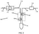
- FIG. 3is similar to FIG. 1 , but depicts a condition in which the flow regulator is not supplying fluid to the valve assembly, and therefore even though the power supply is supplying fluid to the valve assembly, neither fluid is supplied to the torch.
- pressure-actuated valveis intended to encompass any valve that is actuated to change states (open to closed, or closed to open) either via a mechanical pressure-sensing element (e.g., a piston operated upon by fluid pressure) that physically moves a valve element, or via a pressure sensor that senses pressure of a fluid and communicates with a suitable actuator (e.g., a solenoid or the like) that moves the valve element based on the sensed pressure.
- a mechanical pressure-sensing elemente.g., a piston operated upon by fluid pressure
- a pressure sensorthat senses pressure of a fluid and communicates with a suitable actuator (e.g., a solenoid or the like) that moves the valve element based on the sensed pressure.
- FIGS. 1 through 3flow of a fluid is indicated by an arrow adjacent to the line carrying the fluid, and absence of an arrow indicates absence of fluid in that line. Additionally, a diagonal slash (“/”) through a valve indicates the valve is open, and absence of the slash indicates the valve is closed.
- the system 100includes a single-gas power supply 110 that includes a suitable gas flow regulator 111 along with components (not shown) for regulating the electrical power supplied to the torch 10 .
- a fluid(which can be either a plasma gas or a fluid such as a shield gas) is supplied via a line 112 to an inlet of the power supply 110 , through the flow regulator 111 , and is discharged from an outlet of the power supply as a regulated stream through a supply line 114 connected to the outlet.
- the systemincludes a separate flow regulator 116 for regulating the flow of another fluid, which enters the regulator 116 via a line 118 and exits as a regulated stream through a supply line 120 .
- the systemfurther includes a valve assembly 130 coupled between the torch 10 and the supply lines 114 , 120 .
- the valve assemblyhas an inlet and an outlet for fluid, and a first pressure-actuated valve 132 interposed between the inlet and the outlet.
- the inletis connected to the supply line 120 .
- the valve 132shuts off supply of the fluid to the torch when the valve is closed and allows the fluid to be supplied to the torch when the valve is open.
- the valve 132is arranged to be acted upon by pressure of the fluid carried in the other supply line 114 , such that it is opened by pressure of the fluid in the line 114 and is closed when the pressure in the line 114 is below a threshold level.
- fluid carried in the supply line 114is tapped off and supplied to the valve 132 to serve in opening the valve 132 whenever the fluid in the line 114 is being supplied at a sufficient pressure to open the valve.
- the fluid carried in the supply line 120will be supplied to the torch only when the other fluid carried in the supply line 114 is being supplied to the torch by the power supply 110 .
- the valve assembly 130also includes a second inlet and second outlet, and a second pressure-actuated valve 134 therebetween and located downstream of the first pressure-actuated valve 132 .
- the second inletis connected to the supply line 114 .
- the second pressure-actuated valve 134is arranged to be acted upon by pressure of the fluid carried in the supply line 120 , such that it is opened by pressure of the fluid in the line 120 and is closed when the pressure in the line 120 is below a threshold level. In this manner, the fluid carried in the supply line 114 will be supplied to the torch only when the other fluid carried in the supply line 120 is being supplied to the torch.
- the system depicted in FIG. 1can be used with plasma gas supplied through the supply line 114 and secondary gas (e.g., shield gas) supplied through the supply line 118 .
- secondary gase.g., shield gas
- the systemworks in essentially the same way if the gas supplies are switched so that secondary gas (e.g., shield gas) is supplied through the supply line 114 and plasma gas is supplied through the supply line 118 .
- the systemwill work with the “parts in place” systems commonly employed in plasma arc torches, such as described in U.S. Pat. No. 7,087,856 assigned to the assignee of the present application and hereby incorporated herein by reference.
- the typical “parts in place” systemsuch as that described in the '856 patent prevents the torch from operating unless certain conditions are met.
- those conditionsgenerally include at least (1) the electrode and nozzle are properly installed in the torch (as opposed to one or both being absent), and (2) shield gas is flowing through the torch. If the check for either or both of these conditions fails (i.e., if one or more fault conditions are detected), then the torch will not operate.
- the system 100complements and improves upon torch systems having such a “parts in place” system, by preventing any gas from flowing for an extended period of time in any of the various possible system conditions.
- the table belowillustrates all of the possible combinations of gas supply and torch assembly conditions, and the resulting fault conditions, if any, for a blow-back type of plasma arc torch such as described in co-pending application Ser. No. 12/852,772 filed on Aug. 9, 2010, the entire disclosure of which is incorporated herein by reference:
- the valve assembly 100is illustrated as having two pressure-actuated valves, but in some applications a valve assembly having a single pressure-actuated valve can be useful.
- the second pressure-actuated valve 134can be omitted.
- the first fluid carried in the supply line 120will be supplied to the torch only when the second fluid in the supply line 114 is also being supplied to the torch such that the valve 132 is opened. If the second fluid in the line 114 is absent, then the valve 132 will be closed such that no fluids are supplied to the torch.
Landscapes
- Engineering & Computer Science (AREA)
- Physics & Mathematics (AREA)
- Plasma & Fusion (AREA)
- Spectroscopy & Molecular Physics (AREA)
- Mechanical Engineering (AREA)
- Plasma Technology (AREA)
Abstract
Description
| Shield gas | Plasma gas | |||
| Torch | pressure at | pressure at | ||
| properly | inlet of valve | inlet of valve | Gas | |
| assembled? | assembly? | assembly? | Resulting Operating Condition | flowing? |
| Yes | Yes | Yes | Normal operating condition. | Yes |
| Both valves open and both gases | ||||
| flowing (FIG. 1). | ||||
| No | Yes | Yes | Torch will not start because | Only briefly |
| electrode will not be in contact | during the | |||
| with nozzle, resulting in a | parts check | |||
| machine fault. Upon detection of | sequence. | |||
| the fault, the power supply will | ||||
| cut off the supply of one gas, and | ||||
| hence the valve assembly will | ||||
| prevent flow of the other gas. | ||||
| Yes or No | No | Yes | Neither valve will open (FIG. 2). | No |
| The parts check will fail and the | ||||
| machine will indicate a fault. | ||||
| Yes or No | Yes | No | Plasma gas valve will open, but | No |
| shield gas valve will not open | ||||
| because of lack of plasma gas | ||||
| (FIG. 3). Because no shield gas | ||||
| is present, the machine will | ||||
| indicate a fault. | ||||
| Yes or No | No | No | Neither valve will open. The | No |
| parts check will fail and the | ||||
| machine will indicate a fault. | ||||
Claims (5)
Priority Applications (5)
| Application Number | Priority Date | Filing Date | Title |
|---|---|---|---|
| US12/911,400US8283594B2 (en) | 2010-08-09 | 2010-10-25 | System and method for supplying fluids to a plasma arc torch |
| PCT/US2011/057500WO2012061070A1 (en) | 2010-10-25 | 2011-10-24 | System and method for supplying fluids to a plasma arc torch |
| EP11779919.7AEP2633740B1 (en) | 2010-10-25 | 2011-10-24 | System and method for supplying fluids to a plasma arc torch |
| CN201180057473.XACN103229603B (en) | 2010-10-25 | 2011-10-24 | System and method for supplying fluids to a plasma arc torch |
| US13/606,682US8729423B2 (en) | 2010-08-09 | 2012-09-07 | System and method for supplying fluids to a plasma arc torch |
Applications Claiming Priority (2)
| Application Number | Priority Date | Filing Date | Title |
|---|---|---|---|
| US12/852,772US20120031881A1 (en) | 2010-08-09 | 2010-08-09 | Blow-Back Plasma Arc Torch With Shield Fluid-Cooled Electrode |
| US12/911,400US8283594B2 (en) | 2010-08-09 | 2010-10-25 | System and method for supplying fluids to a plasma arc torch |
Related Parent Applications (1)
| Application Number | Title | Priority Date | Filing Date |
|---|---|---|---|
| US12/852,772Continuation-In-PartUS20120031881A1 (en) | 2010-08-09 | 2010-08-09 | Blow-Back Plasma Arc Torch With Shield Fluid-Cooled Electrode |
Related Child Applications (1)
| Application Number | Title | Priority Date | Filing Date |
|---|---|---|---|
| US13/606,682ContinuationUS8729423B2 (en) | 2010-08-09 | 2012-09-07 | System and method for supplying fluids to a plasma arc torch |
Publications (2)
| Publication Number | Publication Date |
|---|---|
| US20120031882A1 US20120031882A1 (en) | 2012-02-09 |
| US8283594B2true US8283594B2 (en) | 2012-10-09 |
Family
ID=44913418
Family Applications (2)
| Application Number | Title | Priority Date | Filing Date |
|---|---|---|---|
| US12/911,400Active2031-01-26US8283594B2 (en) | 2010-08-09 | 2010-10-25 | System and method for supplying fluids to a plasma arc torch |
| US13/606,682ActiveUS8729423B2 (en) | 2010-08-09 | 2012-09-07 | System and method for supplying fluids to a plasma arc torch |
Family Applications After (1)
| Application Number | Title | Priority Date | Filing Date |
|---|---|---|---|
| US13/606,682ActiveUS8729423B2 (en) | 2010-08-09 | 2012-09-07 | System and method for supplying fluids to a plasma arc torch |
Country Status (4)
| Country | Link |
|---|---|
| US (2) | US8283594B2 (en) |
| EP (1) | EP2633740B1 (en) |
| CN (1) | CN103229603B (en) |
| WO (1) | WO2012061070A1 (en) |
Cited By (2)
| Publication number | Priority date | Publication date | Assignee | Title |
|---|---|---|---|---|
| US9510435B2 (en) | 2013-06-24 | 2016-11-29 | Victor Equipment Company | Gas control system for a plasma ARC torch |
| US11701734B2 (en) | 2019-07-25 | 2023-07-18 | The Esab Group, Inc. | Apparatus and methods associated with operating a plasma torch |
Families Citing this family (5)
| Publication number | Priority date | Publication date | Assignee | Title |
|---|---|---|---|---|
| US20140261487A1 (en) | 2013-03-14 | 2014-09-18 | R. J. Reynolds Tobacco Company | Electronic smoking article with improved storage and transport of aerosol precursor compositions |
| US11529015B2 (en) | 2019-06-06 | 2022-12-20 | B/E Aerospace, Inc. | Beverage maker platen overflow sensing system |
| US11337548B2 (en)* | 2019-06-06 | 2022-05-24 | B/E Aerospace, Inc. | Pressure sensor overflow interlock system for beverage maker |
| US11540663B2 (en)* | 2019-06-06 | 2023-01-03 | B/E Aerospace, Inc. | Differential pressure flow meter for beverage maker |
| US20210178507A1 (en)* | 2019-12-13 | 2021-06-17 | Norsk Titanium As | Volumetric plasma gas flow measurement and control system for metal-based wire-plasma arc additive manufacturing applications |
Citations (26)
| Publication number | Priority date | Publication date | Assignee | Title |
|---|---|---|---|---|
| US3242305A (en) | 1963-07-03 | 1966-03-22 | Union Carbide Corp | Pressure retract arc torch |
| US4389559A (en) | 1981-01-28 | 1983-06-21 | Eutectic Corporation | Plasma-transferred-arc torch construction |
| US4788408A (en) | 1987-05-08 | 1988-11-29 | The Perkin-Elmer Corporation | Arc device with adjustable cathode |
| US5017752A (en) | 1990-03-02 | 1991-05-21 | Esab Welding Products, Inc. | Plasma arc torch starting process having separated generated flows of non-oxidizing and oxidizing gas |
| EP0591018A1 (en) | 1992-10-02 | 1994-04-06 | La Soudure Autogene Francaise | Arc plasma torch and method of application |
| US5396043A (en) | 1988-06-07 | 1995-03-07 | Hypertherm, Inc. | Plasma arc cutting process and apparatus using an oxygen-rich gas shield |
| US5409164A (en) | 1992-11-20 | 1995-04-25 | La Soudure Autogrene Francaise | Plasma cutting torch |
| US5796067A (en) | 1995-10-30 | 1998-08-18 | The Lincoln Electric Company | Plasma arc torches and methods of operating and testing the same |
| US5801355A (en)* | 1994-05-25 | 1998-09-01 | Komatsu Ltd. | Plasma piercing with non-oxidative plasma gas and plasma cutting with oxidative plasma gas |
| US5856647A (en) | 1997-03-14 | 1999-01-05 | The Lincoln Electric Company | Drag cup for plasma arc torch |
| US5859403A (en) | 1996-07-18 | 1999-01-12 | Trafimet S.P.A. | Plasma torch without high-frequency ignition, with improved electrode air-cooling devices |
| WO1999004925A1 (en) | 1997-07-21 | 1999-02-04 | Ford Global Technologies, Inc. | Plasma arc spot welding of car body |
| US6084199A (en) | 1997-08-01 | 2000-07-04 | Hypertherm, Inc. | Plasma arc torch with vented flow nozzle retainer |
| US6232575B1 (en)* | 1998-10-28 | 2001-05-15 | The Esab Group, Inc. | Apparatus and method for supplying fluids to a plasma arc torch |
| US20030213783A1 (en) | 2002-04-19 | 2003-11-20 | Kinerson Kevin J. | Plasma arc torch cooling system |
| US20050045600A1 (en) | 2003-08-29 | 2005-03-03 | Tatham David A. | Gas flow pre-charge for a plasma arc torch |
| EP1599075A2 (en) | 2004-05-18 | 2005-11-23 | The Esab Group, Inc. | Plasma arc torch |
| US20060163216A1 (en) | 2005-01-27 | 2006-07-27 | Hypertherm, Inc. | Automatic gas control for a plasma arc torch |
| US7087856B2 (en) | 2004-11-03 | 2006-08-08 | The Esab Group, Inc. | System and method for determining an operational condition of a torch |
| US7105770B2 (en) | 2005-01-26 | 2006-09-12 | The Esab Group, Inc. | Plasma arc torch |
| US20080217305A1 (en) | 2007-02-16 | 2008-09-11 | Hypertherm, Inc. | Gas-Cooled Plasma Arc Cutting Torch |
| US20090057276A1 (en) | 2007-09-04 | 2009-03-05 | Thermal Dynamics Corporation | Hybrid shield device for a plasma arc torch |
| US7598473B2 (en) | 2005-05-11 | 2009-10-06 | Hypertherm, Inc. | Generating discrete gas jets in plasma arc torch applications |
| US20100258534A1 (en) | 2009-04-08 | 2010-10-14 | Russell Vernon Hughes | Method of converting a gas tungsten arc welding system to a plasma welding system |
| WO2012021236A1 (en) | 2010-08-09 | 2012-02-16 | The Esab Group, Inc. | Blow-back plasma arc torch with shield fluid-cooled electrode |
| US8129652B2 (en)* | 2007-10-30 | 2012-03-06 | GM Global Technology Operations LLC | Welding stability system and method |
Family Cites Families (9)
| Publication number | Priority date | Publication date | Assignee | Title |
|---|---|---|---|---|
| US4902871A (en) | 1987-01-30 | 1990-02-20 | Hypertherm, Inc. | Apparatus and process for cooling a plasma arc electrode |
| WO1999049025A2 (en) | 1998-03-27 | 1999-09-30 | The Regents Of The University Of California | Human vault rna |
| US6320156B1 (en) | 1999-05-10 | 2001-11-20 | Komatsu Ltd. | Plasma processing device, plasma torch and method for replacing components of same |
| FR2805193B1 (en) | 2000-02-18 | 2002-05-10 | Safmatic | CONTROL OF THE SENDING OF THE PLASMA CUTTING GAS FROM THE PRESSURE OF THE PILOT GAS |
| JP2004351449A (en) | 2003-05-28 | 2004-12-16 | Komatsu Sanki Kk | Plasma cutting device and its controller |
| CN2623398Y (en)* | 2003-06-27 | 2004-07-07 | 沈阳工业学院 | Melting pole oxidizability gas proportioning equipment for welding |
| CN200953682Y (en)* | 2006-06-07 | 2007-09-26 | 清华大学 | Atmospheric pressure discharge cold plasma generator based on dual gas sources |
| CN201070703Y (en)* | 2007-06-29 | 2008-06-11 | 林圣强 | Shielding gas secondary regulation device for argon arc-welding set |
| CN101850458B (en)* | 2009-03-31 | 2013-04-03 | 株式会社三社电机制作所 | Protection gas controlling device and welding device |
- 2010
- 2010-10-25USUS12/911,400patent/US8283594B2/enactiveActive
- 2011
- 2011-10-24WOPCT/US2011/057500patent/WO2012061070A1/enactiveApplication Filing
- 2011-10-24EPEP11779919.7Apatent/EP2633740B1/ennot_activeNot-in-force
- 2011-10-24CNCN201180057473.XApatent/CN103229603B/enactiveActive
- 2012
- 2012-09-07USUS13/606,682patent/US8729423B2/enactiveActive
Patent Citations (28)
| Publication number | Priority date | Publication date | Assignee | Title |
|---|---|---|---|---|
| US3242305A (en) | 1963-07-03 | 1966-03-22 | Union Carbide Corp | Pressure retract arc torch |
| US4389559A (en) | 1981-01-28 | 1983-06-21 | Eutectic Corporation | Plasma-transferred-arc torch construction |
| US4788408A (en) | 1987-05-08 | 1988-11-29 | The Perkin-Elmer Corporation | Arc device with adjustable cathode |
| US5396043A (en) | 1988-06-07 | 1995-03-07 | Hypertherm, Inc. | Plasma arc cutting process and apparatus using an oxygen-rich gas shield |
| US5017752A (en) | 1990-03-02 | 1991-05-21 | Esab Welding Products, Inc. | Plasma arc torch starting process having separated generated flows of non-oxidizing and oxidizing gas |
| EP0591018A1 (en) | 1992-10-02 | 1994-04-06 | La Soudure Autogene Francaise | Arc plasma torch and method of application |
| US5409164A (en) | 1992-11-20 | 1995-04-25 | La Soudure Autogrene Francaise | Plasma cutting torch |
| US5801355A (en)* | 1994-05-25 | 1998-09-01 | Komatsu Ltd. | Plasma piercing with non-oxidative plasma gas and plasma cutting with oxidative plasma gas |
| US5796067A (en) | 1995-10-30 | 1998-08-18 | The Lincoln Electric Company | Plasma arc torches and methods of operating and testing the same |
| US5938949A (en) | 1995-10-30 | 1999-08-17 | Lincoln Global, Inc. | Plasma arc torch |
| US5859403A (en) | 1996-07-18 | 1999-01-12 | Trafimet S.P.A. | Plasma torch without high-frequency ignition, with improved electrode air-cooling devices |
| US5856647A (en) | 1997-03-14 | 1999-01-05 | The Lincoln Electric Company | Drag cup for plasma arc torch |
| WO1999004925A1 (en) | 1997-07-21 | 1999-02-04 | Ford Global Technologies, Inc. | Plasma arc spot welding of car body |
| US6084199A (en) | 1997-08-01 | 2000-07-04 | Hypertherm, Inc. | Plasma arc torch with vented flow nozzle retainer |
| US6232575B1 (en)* | 1998-10-28 | 2001-05-15 | The Esab Group, Inc. | Apparatus and method for supplying fluids to a plasma arc torch |
| US20030213783A1 (en) | 2002-04-19 | 2003-11-20 | Kinerson Kevin J. | Plasma arc torch cooling system |
| US20050045600A1 (en) | 2003-08-29 | 2005-03-03 | Tatham David A. | Gas flow pre-charge for a plasma arc torch |
| EP1599075A2 (en) | 2004-05-18 | 2005-11-23 | The Esab Group, Inc. | Plasma arc torch |
| US7087856B2 (en) | 2004-11-03 | 2006-08-08 | The Esab Group, Inc. | System and method for determining an operational condition of a torch |
| US7105770B2 (en) | 2005-01-26 | 2006-09-12 | The Esab Group, Inc. | Plasma arc torch |
| US20080006614A1 (en) | 2005-01-27 | 2008-01-10 | Hypertherm, Inc. | Method and apparatus for automatic gas control for a plasma arc torch |
| US20060163216A1 (en) | 2005-01-27 | 2006-07-27 | Hypertherm, Inc. | Automatic gas control for a plasma arc torch |
| US7598473B2 (en) | 2005-05-11 | 2009-10-06 | Hypertherm, Inc. | Generating discrete gas jets in plasma arc torch applications |
| US20080217305A1 (en) | 2007-02-16 | 2008-09-11 | Hypertherm, Inc. | Gas-Cooled Plasma Arc Cutting Torch |
| US20090057276A1 (en) | 2007-09-04 | 2009-03-05 | Thermal Dynamics Corporation | Hybrid shield device for a plasma arc torch |
| US8129652B2 (en)* | 2007-10-30 | 2012-03-06 | GM Global Technology Operations LLC | Welding stability system and method |
| US20100258534A1 (en) | 2009-04-08 | 2010-10-14 | Russell Vernon Hughes | Method of converting a gas tungsten arc welding system to a plasma welding system |
| WO2012021236A1 (en) | 2010-08-09 | 2012-02-16 | The Esab Group, Inc. | Blow-back plasma arc torch with shield fluid-cooled electrode |
Non-Patent Citations (2)
| Title |
|---|
| International Search Report and Written Opinion for Application No. PCT/US2011/057500 dated Mar. 29, 2012. |
| International Search Report and Written Opinion for International Application No. PCT/US2011/043495, mailed Dec. 8, 2011. |
Cited By (2)
| Publication number | Priority date | Publication date | Assignee | Title |
|---|---|---|---|---|
| US9510435B2 (en) | 2013-06-24 | 2016-11-29 | Victor Equipment Company | Gas control system for a plasma ARC torch |
| US11701734B2 (en) | 2019-07-25 | 2023-07-18 | The Esab Group, Inc. | Apparatus and methods associated with operating a plasma torch |
Also Published As
| Publication number | Publication date |
|---|---|
| CN103229603A (en) | 2013-07-31 |
| US20120031882A1 (en) | 2012-02-09 |
| US20130062322A1 (en) | 2013-03-14 |
| CN103229603B (en) | 2015-07-08 |
| WO2012061070A1 (en) | 2012-05-10 |
| US8729423B2 (en) | 2014-05-20 |
| EP2633740A1 (en) | 2013-09-04 |
| EP2633740B1 (en) | 2014-06-25 |
Similar Documents
| Publication | Publication Date | Title |
|---|---|---|
| US8729423B2 (en) | System and method for supplying fluids to a plasma arc torch | |
| US7605341B2 (en) | Metering system and method for supplying gas to a torch | |
| WO2012021236A1 (en) | Blow-back plasma arc torch with shield fluid-cooled electrode | |
| US20150059879A1 (en) | Poppet valve | |
| US9625917B2 (en) | Gas pressure regulator with guide | |
| WO2013136914A1 (en) | Control valve | |
| US20120187318A1 (en) | Gas valve with improving safety structure | |
| KR20190056570A (en) | High-pressure gas supplying apparatus | |
| CN100400960C (en) | Valve system for inert gas | |
| JP2016091890A (en) | Fuel supply unit | |
| US9876241B2 (en) | Fuel supply unit | |
| WO2007145685A2 (en) | Shielded gas welder shutdown system | |
| EP1150194B1 (en) | A gas pressure regulator | |
| CN116816997B (en) | Flow-controllable electronic pressure regulating device | |
| US20250283540A1 (en) | Bi-stable valve | |
| KR200495925Y1 (en) | Waste high-pressure gas recovery structure by manual pressure control | |
| JP4645805B2 (en) | Fuel cell system | |
| JP6282214B2 (en) | Fuel supply unit | |
| CN219673972U (en) | Novel gas busbar and novel gas busbar system | |
| JP2019108924A (en) | Relief valve and gas fuel supply unit | |
| JP2009108763A (en) | Gaseous fuel supply device and pressure drop piping identification method | |
| JP2004360632A (en) | Fuel pressure rise prevention device for lpg injection type engine | |
| EP2848844A1 (en) | Valve assembly | |
| EP0919897A2 (en) | A pilot-operated gas pressure regulator with counterbalanced sleeve | |
| JP4821636B2 (en) | Atomic absorption spectrophotometer |
Legal Events
| Date | Code | Title | Description |
|---|---|---|---|
| AS | Assignment | Owner name:THE ESAB GROUP, INC., SOUTH CAROLINA Free format text:ASSIGNMENT OF ASSIGNORS INTEREST;ASSIGNOR:GRIFFIN, DAVID C.;REEL/FRAME:025189/0700 Effective date:20101025 | |
| STCF | Information on status: patent grant | Free format text:PATENTED CASE | |
| AS | Assignment | Owner name:DISTRIBUTION MINING & EQUIPMENT COMPANY, LLC, DELAWARE Free format text:RELEASE BY SECURED PARTY;ASSIGNOR:DEUTSCHE BANK AG NEW YORK BRANCH;REEL/FRAME:035903/0051 Effective date:20150605 Owner name:HOWDEN NORTH AMERICA INC., SOUTH CAROLINA Free format text:RELEASE BY SECURED PARTY;ASSIGNOR:DEUTSCHE BANK AG NEW YORK BRANCH;REEL/FRAME:035903/0051 Effective date:20150605 Owner name:VICTOR EQUIPMENT COMPANY, MISSOURI Free format text:RELEASE BY SECURED PARTY;ASSIGNOR:DEUTSCHE BANK AG NEW YORK BRANCH;REEL/FRAME:035903/0051 Effective date:20150605 Owner name:HOWDEN AMERICAN FAN COMPANY, SOUTH CAROLINA Free format text:RELEASE BY SECURED PARTY;ASSIGNOR:DEUTSCHE BANK AG NEW YORK BRANCH;REEL/FRAME:035903/0051 Effective date:20150605 Owner name:IMO INDUSTRIES INC., DELAWARE Free format text:RELEASE BY SECURED PARTY;ASSIGNOR:DEUTSCHE BANK AG NEW YORK BRANCH;REEL/FRAME:035903/0051 Effective date:20150605 Owner name:ESAB AB, SWEDEN Free format text:RELEASE BY SECURED PARTY;ASSIGNOR:DEUTSCHE BANK AG NEW YORK BRANCH;REEL/FRAME:035903/0051 Effective date:20150605 Owner name:CLARUS FLUID INTELLIGENCE, LLC, WASHINGTON Free format text:RELEASE BY SECURED PARTY;ASSIGNOR:DEUTSCHE BANK AG NEW YORK BRANCH;REEL/FRAME:035903/0051 Effective date:20150605 Owner name:ANDERSON GROUP INC., SOUTH CAROLINA Free format text:RELEASE BY SECURED PARTY;ASSIGNOR:DEUTSCHE BANK AG NEW YORK BRANCH;REEL/FRAME:035903/0051 Effective date:20150605 Owner name:TOTAL LUBRICATION MANAGEMENT COMPANY, TEXAS Free format text:RELEASE BY SECURED PARTY;ASSIGNOR:DEUTSCHE BANK AG NEW YORK BRANCH;REEL/FRAME:035903/0051 Effective date:20150605 Owner name:DISTRIBUTION MINING & EQUIPMENT COMPANY, LLC, DELA Free format text:RELEASE BY SECURED PARTY;ASSIGNOR:DEUTSCHE BANK AG NEW YORK BRANCH;REEL/FRAME:035903/0051 Effective date:20150605 Owner name:ALCOTEC WIRE CORPORATION, MICHIGAN Free format text:RELEASE BY SECURED PARTY;ASSIGNOR:DEUTSCHE BANK AG NEW YORK BRANCH;REEL/FRAME:035903/0051 Effective date:20150605 Owner name:CONSTELLATION PUMPS CORPORATION, DELAWARE Free format text:RELEASE BY SECURED PARTY;ASSIGNOR:DEUTSCHE BANK AG NEW YORK BRANCH;REEL/FRAME:035903/0051 Effective date:20150605 Owner name:EMSA HOLDINGS INC., SOUTH CAROLINA Free format text:RELEASE BY SECURED PARTY;ASSIGNOR:DEUTSCHE BANK AG NEW YORK BRANCH;REEL/FRAME:035903/0051 Effective date:20150605 Owner name:ALLOY RODS GLOBAL INC., DELAWARE Free format text:RELEASE BY SECURED PARTY;ASSIGNOR:DEUTSCHE BANK AG NEW YORK BRANCH;REEL/FRAME:035903/0051 Effective date:20150605 Owner name:COLFAX CORPORATION, MARYLAND Free format text:RELEASE BY SECURED PARTY;ASSIGNOR:DEUTSCHE BANK AG NEW YORK BRANCH;REEL/FRAME:035903/0051 Effective date:20150605 Owner name:HOWDEN GROUP LIMITED, SCOTLAND Free format text:RELEASE BY SECURED PARTY;ASSIGNOR:DEUTSCHE BANK AG NEW YORK BRANCH;REEL/FRAME:035903/0051 Effective date:20150605 Owner name:STOODY COMPANY, MISSOURI Free format text:RELEASE BY SECURED PARTY;ASSIGNOR:DEUTSCHE BANK AG NEW YORK BRANCH;REEL/FRAME:035903/0051 Effective date:20150605 Owner name:VICTOR TECHNOLOGIES INTERNATIONAL, INC., MISSOURI Free format text:RELEASE BY SECURED PARTY;ASSIGNOR:DEUTSCHE BANK AG NEW YORK BRANCH;REEL/FRAME:035903/0051 Effective date:20150605 Owner name:HOWDEN COMPRESSORS, INC., SOUTH CAROLINA Free format text:RELEASE BY SECURED PARTY;ASSIGNOR:DEUTSCHE BANK AG NEW YORK BRANCH;REEL/FRAME:035903/0051 Effective date:20150605 Owner name:SHAWEBONE HOLDINGS INC., SOUTH CAROLINA Free format text:RELEASE BY SECURED PARTY;ASSIGNOR:DEUTSCHE BANK AG NEW YORK BRANCH;REEL/FRAME:035903/0051 Effective date:20150605 Owner name:THE ESAB GROUP INC., SOUTH CAROLINA Free format text:RELEASE BY SECURED PARTY;ASSIGNOR:DEUTSCHE BANK AG NEW YORK BRANCH;REEL/FRAME:035903/0051 Effective date:20150605 | |
| FPAY | Fee payment | Year of fee payment:4 | |
| MAFP | Maintenance fee payment | Free format text:PAYMENT OF MAINTENANCE FEE, 8TH YEAR, LARGE ENTITY (ORIGINAL EVENT CODE: M1552); ENTITY STATUS OF PATENT OWNER: LARGE ENTITY Year of fee payment:8 | |
| MAFP | Maintenance fee payment | Free format text:PAYMENT OF MAINTENANCE FEE, 12TH YEAR, LARGE ENTITY (ORIGINAL EVENT CODE: M1553); ENTITY STATUS OF PATENT OWNER: LARGE ENTITY Year of fee payment:12 |