US8283177B2 - Fluidic system with washing capabilities for a flow cytometer - Google Patents
Fluidic system with washing capabilities for a flow cytometerDownload PDFInfo
- Publication number
- US8283177B2 US8283177B2US12/476,860US47686009AUS8283177B2US 8283177 B2US8283177 B2US 8283177B2US 47686009 AUS47686009 AUS 47686009AUS 8283177 B2US8283177 B2US 8283177B2
- Authority
- US
- United States
- Prior art keywords
- fluid
- pump
- drawtube
- sheath
- flow rate
- Prior art date
- Legal status (The legal status is an assumption and is not a legal conclusion. Google has not performed a legal analysis and makes no representation as to the accuracy of the status listed.)
- Active, expires
Links
Images


Classifications
- G—PHYSICS
- G01—MEASURING; TESTING
- G01N—INVESTIGATING OR ANALYSING MATERIALS BY DETERMINING THEIR CHEMICAL OR PHYSICAL PROPERTIES
- G01N15/00—Investigating characteristics of particles; Investigating permeability, pore-volume or surface-area of porous materials
- G01N15/10—Investigating individual particles
- G01N15/14—Optical investigation techniques, e.g. flow cytometry
- G01N15/1404—Handling flow, e.g. hydrodynamic focusing
- B—PERFORMING OPERATIONS; TRANSPORTING
- B01—PHYSICAL OR CHEMICAL PROCESSES OR APPARATUS IN GENERAL
- B01L—CHEMICAL OR PHYSICAL LABORATORY APPARATUS FOR GENERAL USE
- B01L13/00—Cleaning or rinsing apparatus
- B01L13/02—Cleaning or rinsing apparatus for receptacle or instruments
- G—PHYSICS
- G05—CONTROLLING; REGULATING
- G05D—SYSTEMS FOR CONTROLLING OR REGULATING NON-ELECTRIC VARIABLES
- G05D7/00—Control of flow
- G05D7/06—Control of flow characterised by the use of electric means
- G05D7/0617—Control of flow characterised by the use of electric means specially adapted for fluid materials
- G05D7/0629—Control of flow characterised by the use of electric means specially adapted for fluid materials characterised by the type of regulator means
- G05D7/0676—Control of flow characterised by the use of electric means specially adapted for fluid materials characterised by the type of regulator means by action on flow sources
- G05D7/0682—Control of flow characterised by the use of electric means specially adapted for fluid materials characterised by the type of regulator means by action on flow sources using a plurality of flow sources
- B—PERFORMING OPERATIONS; TRANSPORTING
- B01—PHYSICAL OR CHEMICAL PROCESSES OR APPARATUS IN GENERAL
- B01L—CHEMICAL OR PHYSICAL LABORATORY APPARATUS FOR GENERAL USE
- B01L3/00—Containers or dishes for laboratory use, e.g. laboratory glassware; Droppers
- B01L3/02—Burettes; Pipettes
- B—PERFORMING OPERATIONS; TRANSPORTING
- B01—PHYSICAL OR CHEMICAL PROCESSES OR APPARATUS IN GENERAL
- B01L—CHEMICAL OR PHYSICAL LABORATORY APPARATUS FOR GENERAL USE
- B01L3/00—Containers or dishes for laboratory use, e.g. laboratory glassware; Droppers
- B01L3/50—Containers for the purpose of retaining a material to be analysed, e.g. test tubes
- B01L3/502—Containers for the purpose of retaining a material to be analysed, e.g. test tubes with fluid transport, e.g. in multi-compartment structures
- B01L3/5027—Containers for the purpose of retaining a material to be analysed, e.g. test tubes with fluid transport, e.g. in multi-compartment structures by integrated microfluidic structures, i.e. dimensions of channels and chambers are such that surface tension forces are important, e.g. lab-on-a-chip
- G—PHYSICS
- G01—MEASURING; TESTING
- G01N—INVESTIGATING OR ANALYSING MATERIALS BY DETERMINING THEIR CHEMICAL OR PHYSICAL PROPERTIES
- G01N15/00—Investigating characteristics of particles; Investigating permeability, pore-volume or surface-area of porous materials
- G01N15/10—Investigating individual particles
- G01N15/14—Optical investigation techniques, e.g. flow cytometry
- G01N15/1404—Handling flow, e.g. hydrodynamic focusing
- G01N2015/1413—Hydrodynamic focussing
- Y—GENERAL TAGGING OF NEW TECHNOLOGICAL DEVELOPMENTS; GENERAL TAGGING OF CROSS-SECTIONAL TECHNOLOGIES SPANNING OVER SEVERAL SECTIONS OF THE IPC; TECHNICAL SUBJECTS COVERED BY FORMER USPC CROSS-REFERENCE ART COLLECTIONS [XRACs] AND DIGESTS
- Y10—TECHNICAL SUBJECTS COVERED BY FORMER USPC
- Y10T—TECHNICAL SUBJECTS COVERED BY FORMER US CLASSIFICATION
- Y10T436/00—Chemistry: analytical and immunological testing
- Y10T436/25—Chemistry: analytical and immunological testing including sample preparation
- Y10T436/25375—Liberation or purification of sample or separation of material from a sample [e.g., filtering, centrifuging, etc.]
Definitions
- This inventionrelates generally to the flow cytometer field, and more specifically to an improved fluidic system in the flow cytometer field.
- the fluidic system of a conventional flow cytometerincorporates an air and/or vacuum pump to pressurize and pump sheath fluid from a high-pressure container to the interrogation zone of a flow cell.
- These fluidic systemsare typically arduous to assemble (which increases the costs of the flow cytometer), heavy to haul (which limits the repair options), and challenging to calibrate (which induces errors in the data).
- a conventional flow cytometeruses a drawtube to draw in a sample fluid.
- the drawtubedraws in a sample fluid through direct contact with the sample fluid. Since old sample remnants and contaminants left in the drawtube can alter the results for future samples, it is important to insure a clean drawtube when switching between different samples.
- Conventional flow cytometerstypically require manual washing (which requires the presence of the user before starting different sample).
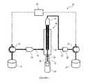
- FIG. 1is a schematic representation of the fluidic system of the preferred embodiment of the invention.
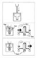
- FIG. 2is a depiction of an embodiment of the preferred washing method.
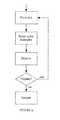
- FIGS. 3 and 4are flow diagrams of an embodiment of the preferred washing method.
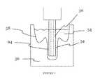
- FIGS. 5-7are schematic views of the washing station of a preferred embodiment of the invention.
- FIGS. 8( a ) and 8 ( b )are detailed schematic views of two variations of a drawtube scrubber.
- the fluidic system 10 of the preferred embodimentincludes a sheath pump 12 to pump sheath fluid 14 from a sheath container 16 into an interrogation zone 18 and a waste pump 20 to pump the sheath fluid 14 and a sample fluid 26 as waste fluid 22 from the interrogation zone 18 into a waste container 24 .
- the sheath pump 12 and/or the waste pump 20draw sample fluid 26 from a sample container 28 into the interrogation zone 18 .
- the fluidic system 10also includes a controller 30 to adjust the flow rate of the sample fluid 26 from the sample container 28 into the interrogation zone 18 .
- the interrogation zone 18functions to provide a location for the fluidic system 10 and an optical system of the flow cytometer to cooperatively facilitate the analysis of the sample fluid 26 .
- the interrogation zone 18is preferably enclosed within a removable flow cell 32 , but may alternatively be defined by any suitable system or device.
- the fluidic system 10is preferably incorporated into a flow cytometer, but may be alternatively incorporated into any suitable system that pumps a first fluid from a first container into an interrogation zone, draws a second fluid from a second container into the interrogation zone, and pumps the combined fluids from the interrogation zone into a third container.
- the sheath pump 12 of the preferred embodimentfunctions to pump sheath fluid 14 from a sheath container 16 into an interrogation zone 18 .
- the sheath fluid 14functions to hydrodynamically focus the sample fluid 26 .
- the process of hydrodynamic focusingresults in laminar flow of the sample fluid 26 within the flow cell 32 and enables the optical system to illuminate, and thus analyze, the particles within the sample fluid 26 with uniformity and repeatability.
- the sheath fluid 14is buffered saline or de-ionized water, but the sheath fluid 14 may alternatively be any suitable fluid to hydrodynamically focus the sample fluid 26 .
- the sheath container 16functions to contain the sheath fluid 14 .
- the sheath container 16is preferably a vented tank with a volume of approximately 1 L, but the sheath tank may alternatively be any suitable container to contain the sheath fluid 14 .
- the sheath pump 12is a positive displacement pump. More preferably, the sheath pump 12 is a peristaltic pump with a flexible tube and one or more cams that pump the sheath fluid 14 through the flexible tube.
- the sheath pump 12preferably has a known flow rate to pump speed ratio, such that control of the speed of the sheath pump 12 corresponds to a control of the flow rate of the sheath fluid 14 . With this pump type, the fluidic system 10 is relatively easy to assemble, light to haul, quick to control, and easy to clean.
- the sheath pump 12may be any suitable pump that pumps sheath fluid 14 from a sheath container 16 into an interrogation zone 18 .
- the waste pump 20 of the preferred embodimentfunctions to pump the waste fluid 22 from the interrogation zone 18 into a waste container 24 .
- the waste fluid 22includes the sheath fluid 14 and the sample fluid 26 .
- the waste fluid 22may include any fluid that exits the interrogation zone 18 .
- the waste container 24is preferably a vented tank with a volume of approximately 1 L, but the waste tank may alternatively be any suitable container to contain the waste fluid 22 .
- the waste pump 20is preferably a positive displacement pump and more preferably a peristaltic pump with a flexible tube and one or more cams that pump the waste fluid 22 through the flexible tube.
- the waste pump 20preferably has a known flow rate to pump speed ratio, such that control of the speed of the waste pump 20 corresponds to a control of the flow rate of the waste fluid 22 .
- the fluidic system 10is relatively easy to assemble, light to haul, quick to control, and easy to clean.
- the waste pump 20may be any suitable pump that pumps waste fluid 22 from an interrogation zone 18 into an interrogation zone.
- the sheath pump 12 and the waste pump 20 of the preferred embodimentcooperate to draw the sample fluid 26 from the sample container 28 and through a drawtube 34 .
- the sample fluid 26contains particles to be analyzed by the flow cytometer.
- the sample fluid 26is preferably blood, but the sample fluid 26 may alternatively be any suitable fluid to be analyzed by the flow cytometer.
- the sample container 28which functions to contain the sample fluid 26 , is preferably an open beaker with a volume of approximately 5 mL, but may alternatively be any suitable container to contain the sample fluid 26 .
- the drawtube 34functions to convey the sample fluid 26 from the sample container 28 into the interrogation zone 18 , is a conventional drawtube, but may alternatively be any suitable device to convey the sample fluid 26 .
- the sheath pump 12 and the waste pump 20preferably cooperate to draw the sample fluid 26 from the sample container 28 into the interrogation zone 18 through the use of a pressure differential (e.g., the sheath pump 12 “pushes” the sheath fluid 14 and the waste pump 20 “pulls” the sheath fluid 14 and the sample fluid 26 ).
- a pressure differentiale.g., the sheath pump 12 “pushes” the sheath fluid 14 and the waste pump 20 “pulls” the sheath fluid 14 and the sample fluid 26 .
- the fluidic system 10preferably allows for a variable flow rate of the sheath fluid 14 and/or the waste fluid 22 .
- the sheath pump 12 and the waste pump 20are driven by a single motor, but with a variable drive ratio device (e.g., transmission), such that the sheath pump 12 and the waste pump 20 may be operated at different pump speeds and, therefore, allow for a variable flow rate of the sheath fluid 14 and/or the waste fluid 22 .
- the sheath pump 12 and the waste pump 20are driven by a single motor, but the fluidic system 10 includes at least one by-pass valve located near the sheath pump 12 and/or the waste pump 20 . The by-pass valve diverts a variable amount of the fluid flow and, therefore, allows for a variable flow rate of the sheath fluid 14 and/or waste fluid 22 .
- the sheath pump 12 and the waste pump 20are driven by a single motor, but the fluidic system 10 includes at least one restrictive valve located near the sheath pump 12 and/or the waste pump 20 .
- the restrictive valvealters the fluid flow and, therefore, allows for a variable flow rate of the sheath fluid 14 and/or waste fluid 22 .
- the sheath pump 12 and the waste pump 20are driven by separate motors with separate controls and, therefore, allows for a variable flow rate of the sheath fluid 14 and/or waste fluid 22 .
- the fluidic system 10may, however, include other suitable variations that draw the sample fluid 26 from the sample container 28 into the interrogation zone 18 through the use of a pressure differential.
- the controller 30 of the preferred embodimentfunctions to adjust the flow rate of the sample fluid 26 from the sample container 28 into the interrogation zone 18 .
- the controller 30may additionally or alternatively adjust the flow rate of a fluid through the drawtube 34 .
- the controller 30adjusts the flow rate of the sample fluid 26 by adjusting the variable flow rate of the sheath fluid 14 and/or the waste fluid 22 .
- the controller 30adjusts the flow rate of the sample fluid 26 by allowing an adjustable flow rate of the sheath fluid 14 from the sheath container 16 to the interrogation zone 18 , while maintaining a consistent flow rate of the waste fluid 22 from the interrogation zone 18 into the waste container 24 .
- the advantage of this arrangementis a finer control of the flow rate of the sample fluid 26 .
- the controller 30may adjust the flow rate of waste fluid 22 while maintaining the flow rate of the sheath fluid 14 , or may simultaneously adjust the flow rates of the sheath fluid 14 and the waste fluid 22 .
- the controller 30may employ one technique (such as allowing an adjustable flow rate of the sheath fluid 14 , while maintaining a consistent flow rate of the waste fluid 22 ) in most situations, and may employ another technique (such as simultaneously adjusting the flow rates of the sheath fluid 14 and the waste fluid 22 ) in other situations to quickly response to a user input.
- the controller 30is preferably a proportional-integral-derivative (PID) controller, but may alternatively be a proportional-integral (PI) controller, a proportional-derivative (PD) controller, a proportional (P) controller, or any other suitable controller.
- PIDproportional-integral-derivative
- PIproportional-integral
- PDproportional-derivative
- Pproportional controller
- the fluidic system 10 of the preferred embodimentalso includes a valve 42 located between the first fluidic capacitor and the interrogation zone 18 , and a valve 44 located between the interrogation zone 18 and the second fluidic capacitor.
- the valves 42 and 44function to facilitate the control of the sheath fluid 14 and the waste fluid 22 .
- the valves 42 and 44are preferably check-valves, but may alternatively be any suitable valve to facilitate the control of the sheath fluid 14 and the waste fluid 22 .
- the fluidic system 10 of the preferred embodimentis preferably operated with the following steps: (1) pumping sheath fluid 14 from a sheath container 16 into an interrogation zone 18 and pumping the sheath fluid 14 and the sample fluid 26 as waste fluid 22 from the interrogation zone 18 into a waste container 24 , thereby drawing sample fluid 26 from a sample container 28 into the interrogation zone 18 ; and (2) adjusting the flow rate of the sample fluid 26 from the sample container 28 into the interrogation zone 18 .
- step (2)preferably includes allowing a substantially adjustable flow rate of the sheath fluid 14 from the sheath container 16 to the interrogation zone 18 , while maintaining a substantially consistent flow rate of the waste fluid 22 from the interrogation zone 18 into the waste container 24 .
- the operation of the fluidic system 10also preferably includes attenuating pulsations within the sheath fluid 14 and the waste fluid 22 .
- the inventionalso includes a method of washing the drawtube of the fluidic system 10 .
- a first embodiment of the methodincludes the steps: controlling a sheath pump and waste pump of a fluidic system S 110 and flushing a fluid out through the drawtube S 120 , thereby cleaning the fluidic system of the flow cytometer.
- the methodfunctions to use a fluidic system to clean contaminates off a drawtube.
- the fluidic systemis preferably substantially similar to the fluidic system used to draw in samples, and more preferably is substantially similar to the fluidic system described above.
- the sheath pump and waste pumppreferably cooperate to direct the flow of fluid while flushing out fluid from the drawtube and while drawing in fluid through the drawtube.
- Step S 110which includes controlling a sheath pump and waste pump of a fluidic system, functions to adjust the flow rate of a sheath fluid 14 and waste fluid 22 to alter the flow rate and direction of a fluid through the drawtube 34 .
- the sheath pump 12 and waste pump 20are preferably part of a fluidic system substantially similar to the fluidic system described above in design and/or operation.
- the sheath pump 12 and the waste pump 20preferably cooperate to draw in or expel (flush out) a fluid through the drawtube 34 through the use of a pressure differential (e.g., to draw in, the sheath pump 12 “pushes” the sheath fluid 14 and the waste pump 20 “pulls” the sheath fluid 14 and the sample fluid 26 ).
- the fluidic system 10preferably allows for a variable flow rate of the sheath fluid 14 and/or the waste fluid 22 .
- the sheath pump 12 and the waste pump 20are preferably positive displacement pumps and more preferably each peristaltic pump has a flexible tube and one or more cams that pump the sheath fluid 14 or waste fluid 22 through the flexible tube.
- the sheath pump 12 and the waste pump 20preferably have a known flow rate to pump speed ratio, such that control of the speed of the sheath pump 12 or waste pump 20 corresponds to a control of the flow rate of the sheath fluid 14 or waste fluid 22 .
- the waste pump 20may be any suitable pump that pumps waste fluid 22 from a waste container 24 into an interrogation zone 18 .
- Step S 120which includes flushing out the drawtube, functions to remove unwanted sample remnants or contaminants from the inside capillary 50 of the drawtube 34 .
- the step of flushing out the drawtubeis preferably accomplished by pushing out sample and/or sheath fluid (instead of drawing in sample fluid).
- the sheath fluid 14 pressureis set greater than the waste fluid 22 pressure, which flushes the sheath fluid 14 out the drawtube 34 .
- Another way of describing thisis the flow rate of the sheath fluid 22 through the sheath pump 12 is greater than the flow rate of the waste fluid 22 through the waste pump 20 .
- the waste pump 20may be stopped (set at a zero value), or—in some cases—may even be reversed (set at a negative value).
- the sheath pump 12 and waste pump 20are preferably fluidically connected such that the pressure differences alters fluid flow in the fluidic system (and thus through the drawtube 34 ). Ideally, the sheath fluid 34 will flow through the drawtube 34 and remove unwanted sample remnants or contaminants from the inside capillary 50 of the drawtube 34 .
- the sheath pump 12 and waste pump 20are peristaltic pumps, and the controller 30 creates a pressure differential by pumping sheath fluid with the sheath pump 12 and stopping (or even reversing) fluid flow with the waste pump 20 .
- the controller 30can continue to run the sheath pump 12 and waste pump 20 (in a “positive” direction from the interrogation zone to the waste tank), but at rates such that the sheath fluid 14 pressure is greater than the waste fluid 22 pressure.
- a stop valve 52may be positioned between the interrogation zone 18 and the waste pump 20 .
- the stop valve 52ceases or decreases the pressure of the waste fluid 22 below that of the sheath fluid 14 , thereby significantly limiting waste fluid 22 from flowing from the interrogation zone 18 to the waste pump 20 .
- the stop valve 52is preferably a pneumatic valve, but may alternatively be any suitable valve to facilitate the flushing out of the fluidic system.
- the waste pump 20may have a flow rate in the negative direction (towards the interrogation zone), and fluid is preferably flushed out as long as the flow rate of the sheath fluid 14 is greater than the flow rate of waste fluid 22 .
- An additional or alternative step of the preferred embodimentincludes drawing in cleaning fluid 54 S 130 .
- This additional stepallows for a more thorough washing of the drawtube 34 as the cleaning fluid 54 can be run through the entire fluidic system 10 after flushing out.
- the drawing in stepis preferably achieved by operating the sheath and waste pumps in the same manner as when sampling as described above.
- drawing in a cleaning fluid S 130may include pumping a sheath fluid towards the interrogation zone of the flow cytometer at a sheath fluid flow rate and pumping waste fluid from the interrogation zone at a waste fluid flow rate, such that the sheath fluid flow rate is less than the waste fluid flow rate.
- the cleaning fluid 54 drawn into the fluidic system 10is the expelled sheath fluid 14 .
- the methodalso includes aligning a wash station 56 under the drawtube 34 during the washing.
- the wash station 56preferably defines a cavity 58 that functions to hold sheath fluid 14 expelled from the fluidic system 10 after flushing out.
- the wash station 56is preferably made of plastic, rubber, or any other suitable material.
- the end of the drawtube 56is preferably extended down into the cavity 58 . The flushing out and drawing in steps are preferably repeated multiple times.
- the cavity 58may contain a cleaning agent 60 inside the cavity 58 such that expelled sheath fluid 14 mixes with the cleaning agent 60 .
- the cleaning agent 60 and sheath fluid 14in combination add additional further cleaning capabilities when drawn in.
- the cleaning agent 60is preferably any additive that may contribute to the cleaning of the fluidic system, such as bleach.
- the cleaning agent 60may be a powder, a liquid, a gel, a solid, and/or any suitable form that may be mixed with the sheath fluid 14 .
- the expelling of the sheath fluid 14 into the wash station 56preferably contributes to the mixing of the sheath fluid 14 and the cleaning agent 60 .
- An additional or alternative step of the preferred embodimentincludes drawing in a sample fluid.
- the controller 30can preferably initiate pulling a sample fluid into the fluidic system 10 . This step functions to draw in a fluid from the drawtube 34 and facilitate an investigation of the sample.
- a sample container 28is aligned beneath the drawtube 34 and then is pulled into the fluidic system 10 through the drawtube 34 .
- the controller 30preferably sets the sheath pump 12 and waste pump 20 pressure such that the sheath fluid 14 pressure is less than that of the waste fluid 22 pressure, which will draw up a sample fluid 26 through the drawtube 34 to the flow cell 32 .
- the flow rate of the sheath fluid 22 through the sheath pump 12is less than the flow rate of the waste fluid 14 through the waste pump 20 . This is preferably achieved by turning on the waste pump 20 while continuing to run the sheath pump 12 .
- the step of flushing outcan optionally be performed before every new sample fluid 26 is sampled.
- An additional or alternative step of the preferred embodimentincludes washing the outside of the drawtube 34 S 140 . Since the drawtube directly contacts the sample fluid, this step functions to prevent contamination of the subsequent sample fluid by the remnants of the previous sample fluid on the outside of the drawtube.
- a cleaning fluid 54functions to wash the outside of the drawtube 34 .
- the cleaning fluid 54is preferably the expelled sheath fluid.
- the wash station 56facilitates this step by providing the cavity 58 that can be filled to a height sufficient for expelled sheath fluid 14 to wash a significant portion of the outside of the drawtube 34 .
- the drawtube 34is preferably positioned (or inserted) in the cavity 58 so the expelled sheath fluid 14 can rise to the top of the cavity 58 .
- the step of drawing inis preferably performed after this step, and all the expelled sheath fluid is drawn into the fluidic system. Unwanted sample remnants or contaminants from the outside of the drawtube are preferably washed away with the cleaning fluid 54 .
- An additional or alternative step of the preferred embodimentincludes wiping the outside of the drawtube 34 S 150 .
- This stepfunctions to remove contaminates on the outside of the drawtube 34 .
- a drawtube scrubber 112is preferably used to abrasively wipe the outside of the drawtube.
- the drawtube 34preferably penetrates (i.e., passes through) the material of the drawtube scrubber 112 and thereby removes contaminants.
- the drawtube 34may additionally or alternatively, wipe contaminates off during the removal of the drawtube 34 from the wash station 56 , absorb contaminates, disinfect contaminates, or any suitable process that removes or neutralizes contaminates on the outside of the drawtube 34 .
- the wash station 56 of the preferred embodimentfunctions to receive sheath fluid 14 expelled through the drawtube 34 .
- the design of the wash station 56preferably facilitates the washing of the drawtube 34 and the drawing in of cleaning fluid 54 .
- the cavity 58preferably has a width, depth, and shape sufficient to allow the drawtube 34 to be inserted to the bottom of the wash station 56 .
- the cavity 58can preferably be filled with a cleaning fluid 54 to a depth sufficient to rinse the outside of the drawtube 34 .
- the cavity 58is convex in shape with a generally singular low point.
- convex cavity 58is preferably understood to describe any cavity that convexly extends into the wash station 56 , such that the walls of the wash station 56 are concave.
- the cavity 53is preferably conical shaped but may alternatively be a pyramid, have a cylindrical, parabolic or elliptical sides or any suitable form that functions to receive sheath fluid 14 expelled through the drawtube 34 .
- the cavitymay alternatively have any suitable shape that facilitates the cleaning of the drawtube 34 .
- the drawtubeis preferably extended to the bottom of the wash station to the low point. The convex shape functions to minimize the amount of cleaning fluid 54 in the wash station 56 after the cleaning fluid 54 is drawn into the drawtube 34 .
- the wash station 56defines a hole 62 at the bottom of the cavity 58 to function as a drain for the cleaning fluid 54 .
- the hole 62is sufficiently small that the rate of draining is less than the flow rate of expelled sheath fluid 14 . This allows the wash station 56 to be filled with sheath fluid 14 but over time the sheath fluid 14 will drain out through the hole 62 . This allows sheath fluid 14 to optionally be expelled and drawn back into the drawtube 34 or to only be expelled.
- the cavity 58may be designed so that the drawtube 34 has a small gap 64 between the cavity 58 and the drawtube 34 .
- the small gap 46is preferably a fluidic channel defined by the outside surface of the drawtube 34 and a wall off the convex cavity 58 .
- the small gap 64is designed so the volume defined by the small gap 64 is approximately equal to that of the inner capillary 50 of the drawtube 34 .
- This small gap 64functions to maintain the fluidic pressure along the outside of the drawtube 34 as well as the inner capillary 50 .
- a second cavity(or region of the convex cavity 58 ) may additionally be used for collection of fluids pumped through the small gap.
- the wash station 56is preferably located in close proximity to the drawtube 34 so that cleaning may be readily performed before, during, or after an experiment.
- the wash station 56is preferably positioned within a sampling area of a flow cytometer, such that the wash station 56 and drawtube 56 may be automatically aligned for the cleaning process.
- the wash station 56may alternatively be part of a well plate or attached to a well plate or any suitable sample test container.
- the wash station 56may additionally include a drawtube scrubber 112 .
- the drawtube scrubber 112functions to wipe and/or abrasively clean the outside surface of the drawtube 34 prior to inserting the drawtube 34 into the wash station 56 .
- the drawtube scrubber 112is preferably a layer of material attached above the cavity of the wash station that the drawtube 34 must pass through.
- the drawtube scrubber 112may alternatively be positioned to the side of the wash station such as an embodiment that separates the cleaning process of the probe into multiple steps.
- the drawtube 34As the drawtube 34 is being inserted into the cavity of the wash station 56 , the drawtube 34 preferably penetrates (i.e., passes through) the material of the drawtube scrubber 112 and thereby removes contaminants.
- the drawtube 34may additionally or alternatively, wipe contaminates off during the removal of the drawtube 34 from the wash station 56 , absorb contaminates, disinfect contaminates, or any suitable process that removes or neutralizes contaminates on the outside of the drawtube 34 .
- one variation of the drawtube scrubber 112is a block of penetrable material.
- the drawtube 34is preferably inserted in varying locations of the drawtube scrubber 112 to prevent wearing down of material of the drawtube scrubber 112 .
- the drawtube scrubber 112is preferably a block of material that allows insertion of a significant portion of the drawtube 34 .
- the material of the drawtube scrubber 112is preferably hydrophilic to absorb any liquid sample.
- the drawtube scrubber 112may be made of silicon, a sponge, foam, or any suitable material that is penetrable and may aid in cleaning of the drawtube 34 .
- the drawtube scrubber 112may be a container of small particulate material (like sand or grit) that acts to be abrasive and absorptive.
- the small particulate materialis preferably displaced by the drawtube 34 with minimal pressure exerted by the drawtube 34 .
- the small particulate materialmay be contained in a mesh like container above the wash station 56 or may alternatively fill the convex cavity 58 of the wash station 56 .
- a second preferred variation of the drawtube scrubber 112may alternatively be a film positioned across the top of the wash station 56 .
- the friction between the drawtube 34 and the filmpreferably removes contaminants from the drawtube 34 .
- the well plate film 104may be made of an absorbent material that absorbs any excess fluid either on or in the drawtube 34 .
- the drawtube scrubber 112may additionally be replaceable such that after the drawtube scrubber degrades or reaches an end of a lifecycle, a new drawtube scrubber 112 may be attached to the wash station 56 .
- the drawtube scrubber 112is mechanically attached to the top of the wash station 56 , but the drawtube scrubber 112 may alternatively be elastically fit, rest in the cavity, be adhesively attached, or attached in any suitable manner.
- the filmis preferably made of silicon or alternatively, polyethylene, latex, mylar foil, aluminum foil, or any other suitable material. Alternatively, the film may be made from multiple layers of similar or different materials.
- the drawtube 34preferably pierces through the surface of the film.
- the drawtube scrubber 112may additionally or alternatively include a flap valve 116 that functions to allow the drawtube to pass through the film without piercing the material.
- the flap valve 116folds up to seal the opening when the drawtube 34 is not present.
- the flap valve 116is preferably formed by having a slit in the film. A portion of the film material (the “lip”) extends past and under the slit. The pressure of the drawtube 34 pressing on the lip causes the lip to fold downward, allowing the drawtube 34 to pass through the slit. But when no pressure is exerted by the drawtube 34 or outside means, the natural state of the lip is preferably pressed against the slit, thereby sealing the slit. Additionally, the lip preferably facilitates wiping the outside of the drawtube 34 clean of contaminants.
- the flap valve 116may be a circular hole that is pressed closed by internal stresses in the well plate film material or may be any suitable valve with a preexisting opening that can be accessed by exerting pressure with the SIP.
Landscapes
- Chemical & Material Sciences (AREA)
- Physics & Mathematics (AREA)
- General Physics & Mathematics (AREA)
- Health & Medical Sciences (AREA)
- Biochemistry (AREA)
- Dispersion Chemistry (AREA)
- Life Sciences & Earth Sciences (AREA)
- Analytical Chemistry (AREA)
- Chemical Kinetics & Catalysis (AREA)
- General Health & Medical Sciences (AREA)
- Clinical Laboratory Science (AREA)
- Immunology (AREA)
- Pathology (AREA)
- Engineering & Computer Science (AREA)
- Automation & Control Theory (AREA)
- Sampling And Sample Adjustment (AREA)
Abstract
Description
This application is a continuation in part of prior application Ser. No. 11/370,714 filed on 8 Mar. 2006, which is incorporated in its entirety by this reference.
This application also claims the benefit of both U.S. Provisional Application No. 61/082,035 filed on 18 Jul. 2008 and U.S. Provisional Application No. 61/088,660 filed on 13 Aug. 2008, which are both incorporated in their entirety by this reference.
This invention relates generally to the flow cytometer field, and more specifically to an improved fluidic system in the flow cytometer field.
The fluidic system of a conventional flow cytometer incorporates an air and/or vacuum pump to pressurize and pump sheath fluid from a high-pressure container to the interrogation zone of a flow cell. These fluidic systems are typically arduous to assemble (which increases the costs of the flow cytometer), heavy to haul (which limits the repair options), and challenging to calibrate (which induces errors in the data).
A conventional flow cytometer uses a drawtube to draw in a sample fluid. The drawtube draws in a sample fluid through direct contact with the sample fluid. Since old sample remnants and contaminants left in the drawtube can alter the results for future samples, it is important to insure a clean drawtube when switching between different samples. Conventional flow cytometers typically require manual washing (which requires the presence of the user before starting different sample).
Thus, there is a need in the flow cytometer field to create an improved fluidic system, one in which the fluidic system can also wash the drawtube. This invention provides such an improved fluidic system with washing capabilities for a flow cytometer.
The following description of the preferred embodiment of the invention is not intended to limit the invention to this preferred embodiment, but rather to enable any person skilled in the art of flow cytometers to make and use this invention.
1. Sheath Pump, Waste Pump, and Controller
As shown inFIG. 1 , thefluidic system 10 of the preferred embodiment includes asheath pump 12 to pumpsheath fluid 14 from asheath container 16 into aninterrogation zone 18 and awaste pump 20 to pump thesheath fluid 14 and asample fluid 26 aswaste fluid 22 from theinterrogation zone 18 into awaste container 24. Thesheath pump 12 and/or thewaste pump 20draw sample fluid 26 from asample container 28 into theinterrogation zone 18. Thefluidic system 10 also includes acontroller 30 to adjust the flow rate of thesample fluid 26 from thesample container 28 into theinterrogation zone 18. Theinterrogation zone 18 functions to provide a location for thefluidic system 10 and an optical system of the flow cytometer to cooperatively facilitate the analysis of thesample fluid 26. Theinterrogation zone 18 is preferably enclosed within aremovable flow cell 32, but may alternatively be defined by any suitable system or device. Thefluidic system 10 is preferably incorporated into a flow cytometer, but may be alternatively incorporated into any suitable system that pumps a first fluid from a first container into an interrogation zone, draws a second fluid from a second container into the interrogation zone, and pumps the combined fluids from the interrogation zone into a third container.
Thesheath pump 12 of the preferred embodiment functions to pumpsheath fluid 14 from asheath container 16 into aninterrogation zone 18. Thesheath fluid 14 functions to hydrodynamically focus thesample fluid 26. The process of hydrodynamic focusing results in laminar flow of thesample fluid 26 within theflow cell 32 and enables the optical system to illuminate, and thus analyze, the particles within thesample fluid 26 with uniformity and repeatability. Preferably, thesheath fluid 14 is buffered saline or de-ionized water, but thesheath fluid 14 may alternatively be any suitable fluid to hydrodynamically focus thesample fluid 26. Thesheath container 16 functions to contain thesheath fluid 14. Thesheath container 16 is preferably a vented tank with a volume of approximately 1 L, but the sheath tank may alternatively be any suitable container to contain thesheath fluid 14. Preferably, thesheath pump 12 is a positive displacement pump. More preferably, thesheath pump 12 is a peristaltic pump with a flexible tube and one or more cams that pump thesheath fluid 14 through the flexible tube. Thesheath pump 12 preferably has a known flow rate to pump speed ratio, such that control of the speed of thesheath pump 12 corresponds to a control of the flow rate of thesheath fluid 14. With this pump type, thefluidic system 10 is relatively easy to assemble, light to haul, quick to control, and easy to clean. Alternatively, thesheath pump 12 may be any suitable pump that pumpssheath fluid 14 from asheath container 16 into aninterrogation zone 18.
Thewaste pump 20 of the preferred embodiment functions to pump thewaste fluid 22 from theinterrogation zone 18 into awaste container 24. Preferably, thewaste fluid 22 includes thesheath fluid 14 and thesample fluid 26. Alternatively, thewaste fluid 22 may include any fluid that exits theinterrogation zone 18. Thewaste container 24 is preferably a vented tank with a volume of approximately 1 L, but the waste tank may alternatively be any suitable container to contain thewaste fluid 22. Like thesheath pump 12, thewaste pump 20 is preferably a positive displacement pump and more preferably a peristaltic pump with a flexible tube and one or more cams that pump thewaste fluid 22 through the flexible tube. Thewaste pump 20 preferably has a known flow rate to pump speed ratio, such that control of the speed of thewaste pump 20 corresponds to a control of the flow rate of thewaste fluid 22. With this pump type, thefluidic system 10 is relatively easy to assemble, light to haul, quick to control, and easy to clean. Alternatively, thewaste pump 20 may be any suitable pump that pumpswaste fluid 22 from aninterrogation zone 18 into an interrogation zone.
Thesheath pump 12 and thewaste pump 20 of the preferred embodiment cooperate to draw thesample fluid 26 from thesample container 28 and through adrawtube 34. Thesample fluid 26 contains particles to be analyzed by the flow cytometer. Thesample fluid 26 is preferably blood, but thesample fluid 26 may alternatively be any suitable fluid to be analyzed by the flow cytometer. Thesample container 28, which functions to contain thesample fluid 26, is preferably an open beaker with a volume of approximately 5 mL, but may alternatively be any suitable container to contain thesample fluid 26. Thedrawtube 34, functions to convey thesample fluid 26 from thesample container 28 into theinterrogation zone 18, is a conventional drawtube, but may alternatively be any suitable device to convey thesample fluid 26.
Thesheath pump 12 and thewaste pump 20 preferably cooperate to draw thesample fluid 26 from thesample container 28 into theinterrogation zone 18 through the use of a pressure differential (e.g., thesheath pump 12 “pushes” thesheath fluid 14 and thewaste pump 20 “pulls” thesheath fluid 14 and the sample fluid26). In order to allow a variable flow rate of thesample fluid 26, thefluidic system 10 preferably allows for a variable flow rate of thesheath fluid 14 and/or thewaste fluid 22. In a first variation, thesheath pump 12 and thewaste pump 20 are driven by a single motor, but with a variable drive ratio device (e.g., transmission), such that thesheath pump 12 and thewaste pump 20 may be operated at different pump speeds and, therefore, allow for a variable flow rate of thesheath fluid 14 and/or thewaste fluid 22. In a second variation, thesheath pump 12 and thewaste pump 20 are driven by a single motor, but thefluidic system 10 includes at least one by-pass valve located near thesheath pump 12 and/or thewaste pump 20. The by-pass valve diverts a variable amount of the fluid flow and, therefore, allows for a variable flow rate of thesheath fluid 14 and/orwaste fluid 22. In a third variation, thesheath pump 12 and thewaste pump 20 are driven by a single motor, but thefluidic system 10 includes at least one restrictive valve located near thesheath pump 12 and/or thewaste pump 20. The restrictive valve alters the fluid flow and, therefore, allows for a variable flow rate of thesheath fluid 14 and/orwaste fluid 22. In a fourth variation, thesheath pump 12 and thewaste pump 20 are driven by separate motors with separate controls and, therefore, allows for a variable flow rate of thesheath fluid 14 and/orwaste fluid 22. Thefluidic system 10 may, however, include other suitable variations that draw thesample fluid 26 from thesample container 28 into theinterrogation zone 18 through the use of a pressure differential.
Thecontroller 30 of the preferred embodiment functions to adjust the flow rate of thesample fluid 26 from thesample container 28 into theinterrogation zone 18. Thecontroller 30 may additionally or alternatively adjust the flow rate of a fluid through thedrawtube 34. Preferably, thecontroller 30 adjusts the flow rate of thesample fluid 26 by adjusting the variable flow rate of thesheath fluid 14 and/or thewaste fluid 22. More preferably, thecontroller 30 adjusts the flow rate of thesample fluid 26 by allowing an adjustable flow rate of thesheath fluid 14 from thesheath container 16 to theinterrogation zone 18, while maintaining a consistent flow rate of thewaste fluid 22 from theinterrogation zone 18 into thewaste container 24. The advantage of this arrangement is a finer control of the flow rate of thesample fluid 26. Alternatively, thecontroller 30 may adjust the flow rate ofwaste fluid 22 while maintaining the flow rate of thesheath fluid 14, or may simultaneously adjust the flow rates of thesheath fluid 14 and thewaste fluid 22. Furthermore, thecontroller 30 may employ one technique (such as allowing an adjustable flow rate of thesheath fluid 14, while maintaining a consistent flow rate of the waste fluid22) in most situations, and may employ another technique (such as simultaneously adjusting the flow rates of thesheath fluid 14 and the waste fluid22) in other situations to quickly response to a user input. Thecontroller 30 is preferably a proportional-integral-derivative (PID) controller, but may alternatively be a proportional-integral (PI) controller, a proportional-derivative (PD) controller, a proportional (P) controller, or any other suitable controller.
Thefluidic system 10 of the preferred embodiment also includes avalve 42 located between the first fluidic capacitor and theinterrogation zone 18, and avalve 44 located between theinterrogation zone 18 and the second fluidic capacitor. Thevalves sheath fluid 14 and thewaste fluid 22. Thevalves sheath fluid 14 and thewaste fluid 22.
Thefluidic system 10 of the preferred embodiment is preferably operated with the following steps: (1) pumpingsheath fluid 14 from asheath container 16 into aninterrogation zone 18 and pumping thesheath fluid 14 and thesample fluid 26 aswaste fluid 22 from theinterrogation zone 18 into awaste container 24, thereby drawingsample fluid 26 from asample container 28 into theinterrogation zone 18; and (2) adjusting the flow rate of thesample fluid 26 from thesample container 28 into theinterrogation zone 18. As explained above, step (2) preferably includes allowing a substantially adjustable flow rate of thesheath fluid 14 from thesheath container 16 to theinterrogation zone 18, while maintaining a substantially consistent flow rate of thewaste fluid 22 from theinterrogation zone 18 into thewaste container 24. The operation of thefluidic system 10 also preferably includes attenuating pulsations within thesheath fluid 14 and thewaste fluid 22.
2. Washing Capabilities
As shown inFIGS. 2-4 , the invention also includes a method of washing the drawtube of thefluidic system 10. A first embodiment of the method includes the steps: controlling a sheath pump and waste pump of a fluidic system S110 and flushing a fluid out through the drawtube S120, thereby cleaning the fluidic system of the flow cytometer. The method functions to use a fluidic system to clean contaminates off a drawtube. The fluidic system is preferably substantially similar to the fluidic system used to draw in samples, and more preferably is substantially similar to the fluidic system described above. The sheath pump and waste pump preferably cooperate to direct the flow of fluid while flushing out fluid from the drawtube and while drawing in fluid through the drawtube.
Step S110, which includes controlling a sheath pump and waste pump of a fluidic system, functions to adjust the flow rate of asheath fluid 14 andwaste fluid 22 to alter the flow rate and direction of a fluid through thedrawtube 34. Thesheath pump 12 andwaste pump 20 are preferably part of a fluidic system substantially similar to the fluidic system described above in design and/or operation. Thesheath pump 12 and thewaste pump 20 preferably cooperate to draw in or expel (flush out) a fluid through thedrawtube 34 through the use of a pressure differential (e.g., to draw in, thesheath pump 12 “pushes” thesheath fluid 14 and thewaste pump 20 “pulls” thesheath fluid 14 and the sample fluid26). In order to allow a variable flow rate of thesample fluid 26, thefluidic system 10 preferably allows for a variable flow rate of thesheath fluid 14 and/or thewaste fluid 22. Thesheath pump 12 and thewaste pump 20 are preferably positive displacement pumps and more preferably each peristaltic pump has a flexible tube and one or more cams that pump thesheath fluid 14 orwaste fluid 22 through the flexible tube. Thesheath pump 12 and thewaste pump 20 preferably have a known flow rate to pump speed ratio, such that control of the speed of thesheath pump 12 orwaste pump 20 corresponds to a control of the flow rate of thesheath fluid 14 orwaste fluid 22. Alternatively, thewaste pump 20 may be any suitable pump that pumpswaste fluid 22 from awaste container 24 into aninterrogation zone 18.
Step S120, which includes flushing out the drawtube, functions to remove unwanted sample remnants or contaminants from theinside capillary 50 of thedrawtube 34. The step of flushing out the drawtube is preferably accomplished by pushing out sample and/or sheath fluid (instead of drawing in sample fluid). During the flushing out step, thesheath fluid 14 pressure is set greater than thewaste fluid 22 pressure, which flushes thesheath fluid 14 out thedrawtube 34. Another way of describing this is the flow rate of thesheath fluid 22 through thesheath pump 12 is greater than the flow rate of thewaste fluid 22 through thewaste pump 20. This is preferably achieved by pumping asheath fluid 14 at a first flow rate, and pumpingwaste fluid 22 from the interrogation zone at a second flow rate, such that the first flow rate is less than the second flow rate. Alternatively, to achieve a second flow rate less than the first flow rate, thewaste pump 20 may be stopped (set at a zero value), or—in some cases—may even be reversed (set at a negative value). Thesheath pump 12 andwaste pump 20 are preferably fluidically connected such that the pressure differences alters fluid flow in the fluidic system (and thus through the drawtube34). Ideally, thesheath fluid 34 will flow through thedrawtube 34 and remove unwanted sample remnants or contaminants from theinside capillary 50 of thedrawtube 34. Preferably, as described above, thesheath pump 12 andwaste pump 20 are peristaltic pumps, and thecontroller 30 creates a pressure differential by pumping sheath fluid with thesheath pump 12 and stopping (or even reversing) fluid flow with thewaste pump 20. Alternatively, thecontroller 30 can continue to run thesheath pump 12 and waste pump20 (in a “positive” direction from the interrogation zone to the waste tank), but at rates such that thesheath fluid 14 pressure is greater than thewaste fluid 22 pressure. As another alternative, astop valve 52 may be positioned between theinterrogation zone 18 and thewaste pump 20. Thestop valve 52 ceases or decreases the pressure of thewaste fluid 22 below that of thesheath fluid 14, thereby significantly limitingwaste fluid 22 from flowing from theinterrogation zone 18 to thewaste pump 20. Thestop valve 52 is preferably a pneumatic valve, but may alternatively be any suitable valve to facilitate the flushing out of the fluidic system. As an additional alternative thewaste pump 20 may have a flow rate in the negative direction (towards the interrogation zone), and fluid is preferably flushed out as long as the flow rate of thesheath fluid 14 is greater than the flow rate ofwaste fluid 22.
An additional or alternative step of the preferred embodiment includes drawing in cleaningfluid 54 S130. This additional step allows for a more thorough washing of thedrawtube 34 as the cleaningfluid 54 can be run through theentire fluidic system 10 after flushing out. The drawing in step is preferably achieved by operating the sheath and waste pumps in the same manner as when sampling as described above. In particular, drawing in a cleaning fluid S130 may include pumping a sheath fluid towards the interrogation zone of the flow cytometer at a sheath fluid flow rate and pumping waste fluid from the interrogation zone at a waste fluid flow rate, such that the sheath fluid flow rate is less than the waste fluid flow rate. Preferably, the cleaningfluid 54 drawn into thefluidic system 10 is the expelledsheath fluid 14. Alternatively, it could be asecondary cleaning fluid 54 such as deionized water, saline solution, bleach, or any other suitable fluid for cleaning the fluidic system. In the preferred embodiment, the method also includes aligning awash station 56 under thedrawtube 34 during the washing. Thewash station 56 preferably defines acavity 58 that functions to holdsheath fluid 14 expelled from thefluidic system 10 after flushing out. Thewash station 56 is preferably made of plastic, rubber, or any other suitable material. The end of thedrawtube 56 is preferably extended down into thecavity 58. The flushing out and drawing in steps are preferably repeated multiple times. In a variation of the method, thecavity 58 may contain acleaning agent 60 inside thecavity 58 such that expelledsheath fluid 14 mixes with thecleaning agent 60. Thecleaning agent 60 andsheath fluid 14 in combination add additional further cleaning capabilities when drawn in. Thecleaning agent 60 is preferably any additive that may contribute to the cleaning of the fluidic system, such as bleach. Thecleaning agent 60 may be a powder, a liquid, a gel, a solid, and/or any suitable form that may be mixed with thesheath fluid 14. The expelling of thesheath fluid 14 into thewash station 56 preferably contributes to the mixing of thesheath fluid 14 and thecleaning agent 60.
An additional or alternative step of the preferred embodiment includes drawing in a sample fluid. Thecontroller 30 can preferably initiate pulling a sample fluid into thefluidic system 10. This step functions to draw in a fluid from thedrawtube 34 and facilitate an investigation of the sample. Preferably asample container 28 is aligned beneath thedrawtube 34 and then is pulled into thefluidic system 10 through thedrawtube 34. Thecontroller 30 preferably sets thesheath pump 12 andwaste pump 20 pressure such that thesheath fluid 14 pressure is less than that of thewaste fluid 22 pressure, which will draw up asample fluid 26 through thedrawtube 34 to theflow cell 32. Another way of describing this is the flow rate of thesheath fluid 22 through thesheath pump 12 is less than the flow rate of thewaste fluid 14 through thewaste pump 20. This is preferably achieved by turning on thewaste pump 20 while continuing to run thesheath pump 12. The step of flushing out can optionally be performed before everynew sample fluid 26 is sampled.
An additional or alternative step of the preferred embodiment includes washing the outside of thedrawtube 34 S140. Since the drawtube directly contacts the sample fluid, this step functions to prevent contamination of the subsequent sample fluid by the remnants of the previous sample fluid on the outside of the drawtube. In the preferred embodiment, a cleaningfluid 54 functions to wash the outside of thedrawtube 34. The cleaningfluid 54 is preferably the expelled sheath fluid. Thewash station 56 facilitates this step by providing thecavity 58 that can be filled to a height sufficient for expelledsheath fluid 14 to wash a significant portion of the outside of thedrawtube 34. Thedrawtube 34 is preferably positioned (or inserted) in thecavity 58 so the expelledsheath fluid 14 can rise to the top of thecavity 58. The step of drawing in is preferably performed after this step, and all the expelled sheath fluid is drawn into the fluidic system. Unwanted sample remnants or contaminants from the outside of the drawtube are preferably washed away with the cleaningfluid 54.
An additional or alternative step of the preferred embodiment includes wiping the outside of thedrawtube 34 S150. This step functions to remove contaminates on the outside of thedrawtube 34. Adrawtube scrubber 112 is preferably used to abrasively wipe the outside of the drawtube. As thedrawtube 34 is being inserted into thecavity 58 of thewash station 56, thedrawtube 34 preferably penetrates (i.e., passes through) the material of thedrawtube scrubber 112 and thereby removes contaminants. Thedrawtube 34 may additionally or alternatively, wipe contaminates off during the removal of thedrawtube 34 from thewash station 56, absorb contaminates, disinfect contaminates, or any suitable process that removes or neutralizes contaminates on the outside of thedrawtube 34.
3. The Wash Station
As shown inFIG. 5 , thewash station 56 of the preferred embodiment functions to receivesheath fluid 14 expelled through thedrawtube 34. The design of thewash station 56 preferably facilitates the washing of thedrawtube 34 and the drawing in of cleaningfluid 54. Thecavity 58 preferably has a width, depth, and shape sufficient to allow thedrawtube 34 to be inserted to the bottom of thewash station 56. Thecavity 58 can preferably be filled with a cleaningfluid 54 to a depth sufficient to rinse the outside of thedrawtube 34. In one variation, thecavity 58 is convex in shape with a generally singular low point. Here,convex cavity 58 is preferably understood to describe any cavity that convexly extends into thewash station 56, such that the walls of thewash station 56 are concave. The cavity53 is preferably conical shaped but may alternatively be a pyramid, have a cylindrical, parabolic or elliptical sides or any suitable form that functions to receivesheath fluid 14 expelled through thedrawtube 34. The cavity may alternatively have any suitable shape that facilitates the cleaning of thedrawtube 34. The drawtube is preferably extended to the bottom of the wash station to the low point. The convex shape functions to minimize the amount of cleaningfluid 54 in thewash station 56 after the cleaningfluid 54 is drawn into thedrawtube 34. In another variation, as depicted inFIG. 6 , thewash station 56 defines ahole 62 at the bottom of thecavity 58 to function as a drain for the cleaningfluid 54. Preferably, thehole 62 is sufficiently small that the rate of draining is less than the flow rate of expelledsheath fluid 14. This allows thewash station 56 to be filled withsheath fluid 14 but over time thesheath fluid 14 will drain out through thehole 62. This allowssheath fluid 14 to optionally be expelled and drawn back into thedrawtube 34 or to only be expelled. As shown inFIG. 7 , thecavity 58 may be designed so that thedrawtube 34 has asmall gap 64 between thecavity 58 and thedrawtube 34. The small gap46 is preferably a fluidic channel defined by the outside surface of thedrawtube 34 and a wall off theconvex cavity 58. Thesmall gap 64 is designed so the volume defined by thesmall gap 64 is approximately equal to that of theinner capillary 50 of thedrawtube 34. Thissmall gap 64 functions to maintain the fluidic pressure along the outside of thedrawtube 34 as well as theinner capillary 50. A second cavity (or region of the convex cavity58) may additionally be used for collection of fluids pumped through the small gap. Thewash station 56 is preferably located in close proximity to thedrawtube 34 so that cleaning may be readily performed before, during, or after an experiment. Thewash station 56 is preferably positioned within a sampling area of a flow cytometer, such that thewash station 56 anddrawtube 56 may be automatically aligned for the cleaning process. Thewash station 56 may alternatively be part of a well plate or attached to a well plate or any suitable sample test container.
As shown inFIG. 5 , thewash station 56 may additionally include adrawtube scrubber 112. Thedrawtube scrubber 112 functions to wipe and/or abrasively clean the outside surface of thedrawtube 34 prior to inserting thedrawtube 34 into thewash station 56. Thedrawtube scrubber 112 is preferably a layer of material attached above the cavity of the wash station that thedrawtube 34 must pass through. Thedrawtube scrubber 112 may alternatively be positioned to the side of the wash station such as an embodiment that separates the cleaning process of the probe into multiple steps. As thedrawtube 34 is being inserted into the cavity of thewash station 56, thedrawtube 34 preferably penetrates (i.e., passes through) the material of thedrawtube scrubber 112 and thereby removes contaminants. Thedrawtube 34 may additionally or alternatively, wipe contaminates off during the removal of thedrawtube 34 from thewash station 56, absorb contaminates, disinfect contaminates, or any suitable process that removes or neutralizes contaminates on the outside of thedrawtube 34.
As shown inFIG. 8 b, one variation of thedrawtube scrubber 112 is a block of penetrable material. Thedrawtube 34 is preferably inserted in varying locations of thedrawtube scrubber 112 to prevent wearing down of material of thedrawtube scrubber 112. Thedrawtube scrubber 112 is preferably a block of material that allows insertion of a significant portion of thedrawtube 34. The material of thedrawtube scrubber 112 is preferably hydrophilic to absorb any liquid sample. Though, alternatively, thedrawtube scrubber 112 may be made of silicon, a sponge, foam, or any suitable material that is penetrable and may aid in cleaning of thedrawtube 34. In another variation, thedrawtube scrubber 112 may be a container of small particulate material (like sand or grit) that acts to be abrasive and absorptive. The small particulate material is preferably displaced by thedrawtube 34 with minimal pressure exerted by thedrawtube 34. The small particulate material may be contained in a mesh like container above thewash station 56 or may alternatively fill theconvex cavity 58 of thewash station 56.
As shown inFIG. 8 a, a second preferred variation of thedrawtube scrubber 112 may alternatively be a film positioned across the top of thewash station 56. During insertion and removal, the friction between the drawtube34 and the film preferably removes contaminants from thedrawtube 34. Alternatively and/or additionally, the well plate film104 may be made of an absorbent material that absorbs any excess fluid either on or in thedrawtube 34. Thedrawtube scrubber 112 may additionally be replaceable such that after the drawtube scrubber degrades or reaches an end of a lifecycle, anew drawtube scrubber 112 may be attached to thewash station 56. Preferably thedrawtube scrubber 112 is mechanically attached to the top of thewash station 56, but thedrawtube scrubber 112 may alternatively be elastically fit, rest in the cavity, be adhesively attached, or attached in any suitable manner. The film is preferably made of silicon or alternatively, polyethylene, latex, mylar foil, aluminum foil, or any other suitable material. Alternatively, the film may be made from multiple layers of similar or different materials. Thedrawtube 34 preferably pierces through the surface of the film. Thedrawtube scrubber 112 may additionally or alternatively include a flap valve116 that functions to allow the drawtube to pass through the film without piercing the material. After the drawtube106 is withdrawn, the flap valve116 then folds up to seal the opening when thedrawtube 34 is not present. The flap valve116 is preferably formed by having a slit in the film. A portion of the film material (the “lip”) extends past and under the slit. The pressure of thedrawtube 34 pressing on the lip causes the lip to fold downward, allowing thedrawtube 34 to pass through the slit. But when no pressure is exerted by thedrawtube 34 or outside means, the natural state of the lip is preferably pressed against the slit, thereby sealing the slit. Additionally, the lip preferably facilitates wiping the outside of thedrawtube 34 clean of contaminants. Alternatively, the flap valve116 may be a circular hole that is pressed closed by internal stresses in the well plate film material or may be any suitable valve with a preexisting opening that can be accessed by exerting pressure with the SIP.
As a person skilled in the art of flow cytometers will recognize from the previous detailed description and from the figures and claims, modifications and changes can be made to the preferred embodiment of the invention without departing from the scope of this invention defined in the following claims.
Claims (14)
1. A method for cleaning a fluidic system of a flow cytometer having a sheath pump to pump sheath fluid towards an interrogation zone and a waste pump to pump the sheath fluid and a sample fluid as waste fluid from the interrogation zone, wherein the sheath pump and/or the waste pump draw sample fluid into the flow cytometer through a drawtube towards the interrogation zone, comprising:
controlling the sheath pump and the waste pump to cooperatively flush a fluid out through the drawtube, thereby cleaning the fluidic system of the flow cytometer, including: pumping sheath fluid towards the interrogation zone of the flow cytometer at a first flow rate; and pumping waste fluid from the interrogation zone at a second flow rate; wherein the first flow rate is greater than the second flow rate; and
drawing in a cleaning fluid, including: pumping sheath fluid towards the interrogation zone of the flow cytometer at a third flow rate; and pumping waste fluid from the interrogation zone at a fourth pump flow rate; wherein the third flow rate is less than the fourth flow rate.
2. The method ofclaim 1 , further including depositing flushed out fluid into a wash station.
3. The method ofclaim 2 , further including inserting the drawtube into the wash station.
4. The method ofclaim 3 , further including wiping the outside of the drawtube with a drawtube scrubber.
5. The method ofclaim 4 , wherein the drawtube scrubber is a film that abrasively rubs against the drawtube as the drawtube is inserted into the wash station.
6. The method ofclaim 3 , further including rinsing the outside of the drawtube in fluid collected in a convex cavity of the wash station.
7. The method ofclaim 6 , further including pumping fluid through a channel created by the outside of the drawtube and the walls of the cavity of the wash station.
8. The method ofclaim 1 , wherein the first flow rate and the third flow rate are different flow rates.
9. The method ofclaim 1 , wherein the second flow rate is approximately zero.
10. The method ofclaim 1 , wherein drawing in a cleaning fluid includes:
drawing in a cleaning fluid that comprises at least one of sheath fluid flushed out of the drawtube and a cleaning agent in a wash station.
11. A method for cleaning a fluidic system of a flow cytometer having a sheath pump to pump sheath fluid towards an interrogation zone and a waste pump to pump the sheath fluid and a sample fluid as waste fluid from the interrogation zone, wherein the sheath pump and/or the waste pump draw sample fluid into the flow cytometer through a drawtube towards the interrogation zone, comprising:
controlling the sheath pump and the waste pump to cooperatively flush a fluid out of the fluidic system through the drawtube, thereby cleaning the fluidic system of the flow cytometer, including: pumping sheath fluid towards the interrogation zone of the flow cytometer at a first flow rate and pumping waste fluid from the interrogation zone at a second flow rate, wherein the first flow rate is greater than the second flow rate; and
drawing in a cleaning fluid that is a mixture of sheath fluid flushed out of the drawtube and a cleaning agent in a wash station, wherein drawing in a cleaning fluid includes: pumping sheath fluid towards the interrogation zone of the flow cytometer at a third flow rate; and pumping waste fluid from the interrogation zone at a fourth pump flow rate; wherein the third flow rate is less than the fourth flow rate.
12. The method ofclaim 11 , further comprising inserting the drawtube into the wash station and depositing flushed out fluid into a wash station.
13. The method ofclaim 11 , wherein the first flow rate and the third flow rate are different flow rates.
14. The method ofclaim 11 , wherein the second flow rate is approximately zero.
Priority Applications (1)
| Application Number | Priority Date | Filing Date | Title |
|---|---|---|---|
| US12/476,860US8283177B2 (en) | 2006-03-08 | 2009-06-02 | Fluidic system with washing capabilities for a flow cytometer |
Applications Claiming Priority (4)
| Application Number | Priority Date | Filing Date | Title |
|---|---|---|---|
| US11/370,714US8017402B2 (en) | 2006-03-08 | 2006-03-08 | Fluidic system for a flow cytometer |
| US8203508P | 2008-07-18 | 2008-07-18 | |
| US8866008P | 2008-08-13 | 2008-08-13 | |
| US12/476,860US8283177B2 (en) | 2006-03-08 | 2009-06-02 | Fluidic system with washing capabilities for a flow cytometer |
Related Parent Applications (1)
| Application Number | Title | Priority Date | Filing Date |
|---|---|---|---|
| US11/370,714Continuation-In-PartUS8017402B2 (en) | 2005-10-13 | 2006-03-08 | Fluidic system for a flow cytometer |
Publications (2)
| Publication Number | Publication Date |
|---|---|
| US20090293910A1 US20090293910A1 (en) | 2009-12-03 |
| US8283177B2true US8283177B2 (en) | 2012-10-09 |
Family
ID=41378256
Family Applications (1)
| Application Number | Title | Priority Date | Filing Date |
|---|---|---|---|
| US12/476,860Active2026-12-28US8283177B2 (en) | 2006-03-08 | 2009-06-02 | Fluidic system with washing capabilities for a flow cytometer |
Country Status (1)
| Country | Link |
|---|---|
| US (1) | US8283177B2 (en) |
Cited By (10)
| Publication number | Priority date | Publication date | Assignee | Title |
|---|---|---|---|---|
| US20120103112A1 (en)* | 2010-10-29 | 2012-05-03 | Becton Dickinson And Company | Dual feedback vacuum fluidics for a flow-type particle analyzer |
| US10022720B2 (en) | 2015-06-12 | 2018-07-17 | Cytochip Inc. | Fluidic units and cartridges for multi-analyte analysis |
| US10031061B2 (en) | 2009-05-13 | 2018-07-24 | Intellicyt Corporation | Flow measurement and control for improved quantification of particles in flow cytometry |
| US10077999B2 (en) | 2015-07-14 | 2018-09-18 | Cytochip Inc. | Volume sensing in fluidic cartridge |
| US10634602B2 (en) | 2015-06-12 | 2020-04-28 | Cytochip Inc. | Fluidic cartridge for cytometry and additional analysis |
| US11137337B2 (en) | 2019-01-21 | 2021-10-05 | Essen Instruments, Inc. | Flow cytometry with data analysis for optimized dilution of fluid samples for flow cytometry investigation |
| US11491487B2 (en) | 2017-10-23 | 2022-11-08 | Cytochip Inc. | Devices and methods for measuring analytes and target particles |
| US11709116B2 (en) | 2020-02-04 | 2023-07-25 | Sartorius Bioanalytical Instruments, Inc. | Liquid flourescent dye concentrate for flow cytometry evaluation of virus-size particles and related products and methods |
| US12196652B2 (en) | 2018-08-01 | 2025-01-14 | Sartorius Bioanalytical Instruments, Inc. | Methods, kits and stain compositions for flow cytometry evaluation of unassociated virus-size particles using multiple fluorogenic dyes |
| WO2025132566A1 (en)* | 2023-12-21 | 2025-06-26 | Boehringer Ingelheim International Gmbh | Measuring arrangement and method for analyzing a fluidic sample |
Families Citing this family (25)
| Publication number | Priority date | Publication date | Assignee | Title |
|---|---|---|---|---|
| US8303894B2 (en) | 2005-10-13 | 2012-11-06 | Accuri Cytometers, Inc. | Detection and fluidic system of a flow cytometer |
| US8017402B2 (en) | 2006-03-08 | 2011-09-13 | Accuri Cytometers, Inc. | Fluidic system for a flow cytometer |
| US7780916B2 (en) | 2006-03-08 | 2010-08-24 | Accuri Cytometers, Inc. | Flow cytometer system with unclogging feature |
| US8715573B2 (en) | 2006-10-13 | 2014-05-06 | Accuri Cytometers, Inc. | Fluidic system for a flow cytometer with temporal processing |
| US8445286B2 (en) | 2006-11-07 | 2013-05-21 | Accuri Cytometers, Inc. | Flow cell for a flow cytometer system |
| US8432541B2 (en) | 2007-12-17 | 2013-04-30 | Accuri Cytometers, Inc. | Optical system for a flow cytometer with an interrogation zone |
| WO2010009339A1 (en)* | 2008-07-18 | 2010-01-21 | Accuri Cytometers, Inc. | Wellplate handler system for a flow cytometer |
| US8507279B2 (en) | 2009-06-02 | 2013-08-13 | Accuri Cytometers, Inc. | System and method of verification of a prepared sample for a flow cytometer |
| US9551600B2 (en) | 2010-06-14 | 2017-01-24 | Accuri Cytometers, Inc. | System and method for creating a flow cytometer network |
| US9280635B2 (en) | 2010-10-25 | 2016-03-08 | Accuri Cytometers, Inc. | Systems and user interface for collecting a data set in a flow cytometer |
| CN104487819B (en)* | 2012-06-22 | 2017-10-27 | 生物辐射实验室股份有限公司 | Two standing posture samples and washing system |
| CN104289466B (en)* | 2013-07-16 | 2017-03-15 | 成都深迈瑞医疗电子技术研究院有限公司 | Cytoanalyze and its purging system |
| CN103389265A (en)* | 2013-07-30 | 2013-11-13 | 济南华天恒达科技有限公司 | Sampling and washing system |
| US11556039B2 (en) | 2013-12-17 | 2023-01-17 | Corning Incorporated | Electrochromic coated glass articles and methods for laser processing the same |
| US10293436B2 (en) | 2013-12-17 | 2019-05-21 | Corning Incorporated | Method for rapid laser drilling of holes in glass and products made therefrom |
| WO2017116651A1 (en)* | 2015-12-30 | 2017-07-06 | Life Technologies Corporation | System and method for providing stable fluid flow |
| CN105880204B (en)* | 2016-05-06 | 2017-12-01 | 南京医科大学 | Rapid Cleaning method for cytoanalyze with the drafting board of quality inspection containing auri |
| EP3529214B1 (en) | 2016-10-24 | 2020-12-23 | Corning Incorporated | Substrate processing station for laser-based machining of sheet-like glass substrates |
| EP3837528B1 (en)* | 2018-08-15 | 2025-09-17 | Becton, Dickinson and Company | Flowrate and vacuum controlled fluid management system for a flow type particle analyzer |
| US11237093B2 (en)* | 2018-12-10 | 2022-02-01 | Bio-Rad Laboratories, Inc. | External fluidics system for flow cytometer |
| KR102746380B1 (en)* | 2020-05-19 | 2024-12-24 | 라이프 테크놀로지스 코포레이션 | Nozzle sealing and de-clogging station for flow cytometer |
| CN113109583B (en)* | 2021-04-13 | 2024-02-13 | 亚能生物技术(深圳)有限公司 | Flow cytometer sample test tube processing device |
| CN114160529A (en)* | 2021-10-29 | 2022-03-11 | 常州必达科生物科技有限公司 | Flow-type pool cleaning system and method |
| CN116858783B (en)* | 2023-09-04 | 2023-11-14 | 四川格林泰科生物科技有限公司 | Full-automatic blood analyzer |
| CN118558682B (en)* | 2024-07-31 | 2024-09-27 | 昆明医科大学第一附属医院(云南省皮肤病医院) | Flow cytometer nozzle cleaning system with drying function |
Citations (204)
| Publication number | Priority date | Publication date | Assignee | Title |
|---|---|---|---|---|
| US3347273A (en) | 1965-10-22 | 1967-10-17 | Peters & Russel Inc | Surge chambers employing flexible membranes |
| US3601128A (en) | 1968-12-26 | 1971-08-24 | Salomon Hakim | Ventriculoatrial shunt accumulator |
| US3672402A (en) | 1970-09-14 | 1972-06-27 | Eaton Yale & Towne | Automatic precharge adjuster |
| US4112735A (en) | 1976-09-13 | 1978-09-12 | United Kingdom Atomic Energy Authority | Detection of bubbles in a liquid |
| US4138879A (en) | 1977-08-22 | 1979-02-13 | Tif Instruments, Inc. | Sightless bubble detector |
| US4371786A (en) | 1980-10-29 | 1983-02-01 | Miles Laboratories, Inc. | Method and apparatus for detecting bubbles in a liquid |
| US4448538A (en) | 1982-04-06 | 1984-05-15 | Juval Mantel | Device for reducing static and dynamic pressures in pipelines, particularly of solid-borne sound in tubular conduits |
| US4559454A (en) | 1983-04-01 | 1985-12-17 | Kramer Donald L | Bubble detecting infusion apparatus |
| US4570639A (en) | 1982-12-30 | 1986-02-18 | Memorial Hospital For Cancer And Allied Diseases | Discontinuity detector |
| US4691829A (en) | 1980-11-03 | 1987-09-08 | Coulter Corporation | Method of and apparatus for detecting change in the breakoff point in a droplet generation system |
| US4755021A (en) | 1982-08-02 | 1988-07-05 | Andrew Corporation | Self-aligning optical fiber directional coupler and fiber-ring optical rotation sensor using same |
| US4790653A (en) | 1986-05-22 | 1988-12-13 | Becton Dickinson And Company | Housing for a flow cytometry apparatus with particle unclogging feature |
| US4818103A (en) | 1981-05-15 | 1989-04-04 | Ratcom | Flow cytometry |
| US4824641A (en) | 1986-06-20 | 1989-04-25 | Cetus Corporation | Carousel and tip |
| US4826660A (en) | 1987-05-07 | 1989-05-02 | Becton, Dickinson And Company | Detector assembly for analyzer instrument |
| US4844610A (en) | 1988-04-29 | 1989-07-04 | Becton, Dickinson And Company | Backflow isolator and capture system |
| US4933813A (en) | 1986-04-14 | 1990-06-12 | Berger Daniel S | Sunlight simulator |
| US5028127A (en) | 1989-08-14 | 1991-07-02 | Spitzberg Larry A | Wafer thin reading telescope |
| US5040890A (en) | 1987-11-25 | 1991-08-20 | Becton, Dickinson And Company | Sheathed particle flow controlled by differential pressure |
| US5043706A (en) | 1990-10-19 | 1991-08-27 | Eastman Kodak Company | System and method for detecting bubbles in a flowing fluid |
| US5083862A (en) | 1990-08-13 | 1992-01-28 | City Of Hope | Liquid bubble detector |
| US5139609A (en) | 1991-02-11 | 1992-08-18 | The Aerospace Corporation | Apparatus and method for longitudinal diode bar pumping of solid state lasers |
| US5138868A (en) | 1991-02-13 | 1992-08-18 | Pb Diagnostic Systems, Inc. | Calibration method for automated assay instrument |
| US5150037A (en) | 1990-11-30 | 1992-09-22 | Toa Medical Electronics Co., Ltd. | Particle detector and particle detecting apparatus having the detector |
| US5150313A (en) | 1990-04-12 | 1992-09-22 | Regents Of The University Of California | Parallel pulse processing and data acquisition for high speed, low error flow cytometry |
| US5155543A (en) | 1989-08-22 | 1992-10-13 | Omron Corporation | Adjustable flow cytometer |
| US5204884A (en) | 1991-03-18 | 1993-04-20 | University Of Rochester | System for high-speed measurement and sorting of particles |
| US5224058A (en) | 1990-05-01 | 1993-06-29 | Becton, Dickinson And Company | Method for data transformation |
| US5230026A (en) | 1990-05-18 | 1993-07-20 | Suzuki Motor Corporation | Apparatus for discriminating particle aggregation pattern |
| US5270548A (en) | 1992-07-31 | 1993-12-14 | The United States Of America As Represented By The United States Department Of Energy | Phase-sensitive flow cytometer |
| US5301685A (en) | 1989-01-10 | 1994-04-12 | Guirguis Raouf A | Method and apparatus for obtaining a cytology monolayer |
| US5308990A (en) | 1991-05-15 | 1994-05-03 | Hitachi, Ltd. | Method for measuring microparticles, quantitative measuring method therefor and instrument for measuring microparticles |
| JPH06194299A (en)* | 1992-12-24 | 1994-07-15 | Canon Inc | Flow cell device |
| US5367474A (en) | 1993-02-08 | 1994-11-22 | Coulter Corporation | Flow cytometer |
| US5374395A (en) | 1993-10-14 | 1994-12-20 | Amoco Corporation | Diagnostics instrument |
| US5395588A (en) | 1992-12-14 | 1995-03-07 | Becton Dickinson And Company | Control of flow cytometer having vacuum fluidics |
| US5403552A (en) | 1986-06-05 | 1995-04-04 | Pardikes; Dennis | Module for automatically controlling a polymer processing system |
| JPH07260084A (en) | 1994-03-16 | 1995-10-13 | Tokai Rubber Ind Ltd | Pulsation absorbing device |
| US5466946A (en) | 1993-08-13 | 1995-11-14 | Miles, Inc. | Method and apparatus for discriminating between liquids and gases |
| US5469375A (en) | 1992-01-30 | 1995-11-21 | Toa Medical Electronics Co., Ltd. | Device for identifying the type of particle detected by a particle detecting device |
| US5539386A (en) | 1994-03-07 | 1996-07-23 | J-Kem Electronics, Inc. | Sensor for detecting air/liquid transitions in a transparent tubing |
| JPH08201267A (en)* | 1995-01-27 | 1996-08-09 | Hitachi Ltd | Particle analyzer |
| US5552885A (en) | 1993-03-22 | 1996-09-03 | Steen; Harald | Measuring chamber for flow cytometer |
| US5559339A (en) | 1994-10-31 | 1996-09-24 | Abbott Laboratories | Method and apparatus for verifying dispense of a fluid from a dispense nozzle |
| US5616124A (en) | 1992-03-13 | 1997-04-01 | Ivac Medical Systems, Inc. | Infusion system with air-in-line clear function |
| JPH09288053A (en)* | 1996-02-22 | 1997-11-04 | Hitachi Ltd | Particle analyzer |
| US5684480A (en) | 1995-01-30 | 1997-11-04 | Telefonaktiebolaget Lm Ericsson | Wide dynamic range analog to digital conversion |
| US5739902A (en) | 1993-06-08 | 1998-04-14 | Gjelsnes; Oddbjorn | Liquid flow cytometer |
| US5797430A (en) | 1993-06-04 | 1998-08-25 | Mercedes-Benz Ag | Adaptive hydropneumatic pulsation damper |
| JPH10227737A (en) | 1996-10-15 | 1998-08-25 | Res Electro Opt Inc | Method and device for measuring characteristic of small particle |
| US5798222A (en) | 1995-07-17 | 1998-08-25 | Guava Technologies, Inc. | Apparatus for monitoring substances in organisms |
| US5804507A (en) | 1995-10-27 | 1998-09-08 | Applied Materials, Inc. | Radially oscillating carousel processing system for chemical mechanical polishing |
| US5883378A (en) | 1996-07-30 | 1999-03-16 | Bayer Corporation | Apparatus and methods for transmitting electrical signals indicative of optical interactions between a light beam and a flowing suspension of particles |
| US5960129A (en) | 1997-12-22 | 1999-09-28 | Bayer Corporation | Method and apparatus for detecting liquid and gas segment flow through a tube |
| US5981180A (en) | 1995-10-11 | 1999-11-09 | Luminex Corporation | Multiplexed analysis of clinical specimens apparatus and methods |
| US6016376A (en) | 1997-10-06 | 2000-01-18 | Nec Research Institute, Inc. | Tapered coherent fiber bundle imaging device for near-field optical microscopy |
| US6039078A (en) | 1989-09-22 | 2000-03-21 | Tamari; Yehuda | Inline extracorporeal reservoir and pressure isolator |
| US6067157A (en) | 1998-10-09 | 2000-05-23 | University Of Washington | Dual large angle light scattering detection |
| US6070477A (en) | 1997-07-18 | 2000-06-06 | The Regents Of The University Of California | Collapsible sheath fluid reservoirs for flow cytometers |
| US6091502A (en) | 1998-12-23 | 2000-07-18 | Micronics, Inc. | Device and method for performing spectral measurements in flow cells with spatial resolution |
| US6097485A (en) | 1999-03-08 | 2000-08-01 | Integrated Waveguides, Inc. | Microchip optical transport technology for use in a personal flow cytometer |
| US6108463A (en) | 1996-03-19 | 2000-08-22 | University Of Utah Research Foundation | Lens and associatable flow cell |
| US6110427A (en) | 1998-08-14 | 2000-08-29 | Becton, Dickinson And Company | Flow regulator to maintain controllable volumetric flow rate |
| US6115065A (en) | 1995-11-07 | 2000-09-05 | California Institute Of Technology | Image sensor producing at least two integration times from each sensing pixel |
| US6139800A (en) | 1997-06-23 | 2000-10-31 | Luminex Corporation | Interlaced lasers for multiple fluorescence measurement |
| US6154276A (en) | 1998-02-23 | 2000-11-28 | The Regents Of The University Of California | Waveguide detection of right-angle-scattered light in flow cytometry |
| US6156208A (en) | 1998-05-20 | 2000-12-05 | Institute Guilfoyle | Ferrographic method |
| US6181319B1 (en) | 1997-03-17 | 2001-01-30 | Sysmex Corporation | Method of displaying a scattergram |
| US6183697B1 (en) | 1997-05-27 | 2001-02-06 | Sysmex Corporation | Particle measuring apparatus |
| JP2001050887A (en) | 1999-08-11 | 2001-02-23 | Sysmex Corp | Particle analyzer |
| JP2001170062A (en) | 1999-10-06 | 2001-06-26 | Nidek Co Ltd | Perfusion sucking instrument |
| US20010014477A1 (en) | 1996-05-31 | 2001-08-16 | Pelc Richard E. | Microvolume liquid handling system |
| US6288783B1 (en) | 1996-10-15 | 2001-09-11 | Renner Herrmann S.A. | Fluid analysis system and method, for analyzing characteristic properties of a fluid |
| US20010039053A1 (en)* | 2000-02-29 | 2001-11-08 | John Liseo | Method and apparatus for handling diverse body fluids |
| US20020028434A1 (en) | 2000-09-06 | 2002-03-07 | Guava Technologies, Inc. | Particle or cell analyzer and method |
| US6377721B1 (en) | 1998-03-02 | 2002-04-23 | Trustees Of Tufts College | Biosensor array comprising cell populations confined to microcavities |
| US20020049782A1 (en) | 1999-11-05 | 2002-04-25 | Herzenberg Leonard A. | Internet-linked system for directory protocol based data storage, retrieval and analysis |
| US6382228B1 (en) | 2000-08-02 | 2002-05-07 | Honeywell International Inc. | Fluid driving system for flow cytometry |
| US20020059959A1 (en) | 2002-01-08 | 2002-05-23 | Qatu Mohamad S. | System and apparatus for noise suppression in a fluid line |
| US6403378B1 (en) | 2001-04-26 | 2002-06-11 | Guava Technologies, Inc. | Cell viability assay reagent |
| US20020080341A1 (en) | 2000-12-22 | 2002-06-27 | Sysmex Corporation | Flow cytometer |
| US6427521B2 (en) | 1998-07-10 | 2002-08-06 | Metso Field Systems Oy. | Method and measuring arrangement for measuring gas content of fluid |
| US6431950B1 (en) | 2000-10-18 | 2002-08-13 | Micron Technology, Inc. | Point-of-use fluid regulating system for use in the chemical-mechanical planarization of semiconductor wafers |
| US20020123154A1 (en) | 2000-07-07 | 2002-09-05 | Alexander Burshteyn | Apparatus and method for sample purification and analysis |
| US6456769B1 (en) | 1999-09-02 | 2002-09-24 | Asahi Kogaku Kogyo Kabushiki Kaisha | Fiber bundle and endoscope apparatus |
| US6469787B1 (en) | 2001-04-03 | 2002-10-22 | Ohio Aerospace Institute | Dynamic light scattering homodyne probe |
| US6473171B1 (en) | 1999-01-15 | 2002-10-29 | Coors Brewing Company | Biocompatible apparatus for ultrasensitive and rapid detection of contaminants in liquids |
| US20020192113A1 (en) | 2001-06-13 | 2002-12-19 | Uffenheimer Kenneth F. | Automated fluid handling system and method |
| US6519355B2 (en) | 2001-03-28 | 2003-02-11 | Alan C. Nelson | Optical projection imaging system and method for automatically detecting cells having nuclear and cytoplasmic densitometric features associated with disease |
| US6522775B2 (en) | 2001-03-28 | 2003-02-18 | Alan C. Nelson | Apparatus and method for imaging small objects in a flow stream using optical tomography |
| US20030035168A1 (en) | 2000-05-18 | 2003-02-20 | Qian Charles X.W. | Spectrum division multiplexing for high channel count optical networks |
| US20030048539A1 (en) | 2001-08-28 | 2003-03-13 | Oostman Clifford A. | Fluorescence detection instrument with reflective transfer legs for color decimation |
| US20030054558A1 (en) | 2001-07-18 | 2003-03-20 | Katsuo Kurabayashi | Flow cytometers and detection system of lesser size |
| US20030062314A1 (en) | 1998-05-13 | 2003-04-03 | Chaim Davidson | Method and apparatus for magnetically separating selected particles, particularly biological cells |
| US20030072549A1 (en) | 2000-10-26 | 2003-04-17 | The Trustees Of Princeton University | Method and apparatus for dielectric spectroscopy of biological solutions |
| US20030078703A1 (en) | 2001-10-19 | 2003-04-24 | Surromed, Inc. | Cytometry analysis system and method using database-driven network of cytometers |
| US6568271B2 (en) | 2001-05-08 | 2003-05-27 | Halliburton Energy Services, Inc. | Guided acoustic wave sensor for pipeline build-up monitoring and characterization |
| US6587203B2 (en) | 2000-02-17 | 2003-07-01 | Cornell Research Foundation, Inc. | Sort stream stabilizer for flow cytometer |
| US20030129090A1 (en) | 1999-01-06 | 2003-07-10 | Farrell Gregory A | Variable rate particle counter and method of use |
| US20030134330A1 (en) | 1999-04-15 | 2003-07-17 | Ilya Ravkin | Chemical-library composition and method |
| US6602469B1 (en) | 1998-11-09 | 2003-08-05 | Lifestream Technologies, Inc. | Health monitoring and diagnostic device and network-based health assessment and medical records maintenance system |
| US20030148379A1 (en) | 2002-02-06 | 2003-08-07 | Roitman Daniel B. | Methods for making microbar encoders for bioprobes |
| US20030175157A1 (en) | 2002-01-25 | 2003-09-18 | Irm, Llc | Fluid handling methods and systems |
| JP2003262201A (en) | 2002-03-08 | 2003-09-19 | Nok Corp | Accumulator |
| US6636623B2 (en) | 2001-08-10 | 2003-10-21 | Visiongate, Inc. | Optical projection imaging system and method for automatically detecting cells with molecular marker compartmentalization associated with malignancy and disease |
| US20030202175A1 (en) | 2002-04-24 | 2003-10-30 | Van Den Engh Gerrit J. | Compositions and methods for drop boundary detection and radiation beam alignment |
| US20030211009A1 (en) | 2001-05-18 | 2003-11-13 | Buchanan Kris S. | Rapid multi-material sample input system |
| US20030223061A1 (en) | 2002-06-04 | 2003-12-04 | Lockheed Martin Corporation | Tribological debris analysis system |
| US20030235919A1 (en) | 1998-05-14 | 2003-12-25 | Chandler Van S. | Multi-analyte diagnostic system and computer implemented process for same |
| US6675835B2 (en) | 2001-07-10 | 2004-01-13 | Systec, Inc. | Elliptical tubing in degassing and pulsation dampener application |
| US20040031521A1 (en) | 2002-08-15 | 2004-02-19 | Vrane David R. | Constant output fluidic system |
| US6694799B2 (en) | 2002-02-22 | 2004-02-24 | Eastern Washington University | Method and apparatus for detection of particles |
| US6700130B2 (en) | 2001-06-29 | 2004-03-02 | Honeywell International Inc. | Optical detection system for flow cytometry |
| US20040048362A1 (en) | 1994-02-10 | 2004-03-11 | Mark Trulson | Method and apparatus for imaging a sample on a device |
| US6710871B1 (en) | 1997-06-09 | 2004-03-23 | Guava Technologies, Inc. | Method and apparatus for detecting microparticles in fluid samples |
| US6718415B1 (en) | 1999-05-14 | 2004-04-06 | Acqis Technology, Inc. | Computer system and method including console housing multiple computer modules having independent processing units, mass storage devices, and graphics controllers |
| US20040112808A1 (en) | 2001-03-28 | 2004-06-17 | Yoshiki Takagi | Blood component collection device |
| US20040119974A1 (en) | 2002-12-20 | 2004-06-24 | Bishop James E. | Instrument setup system for a fluorescence analyzer |
| US20040123645A1 (en) | 2000-01-13 | 2004-07-01 | Storm Bruce H. | Single tube densitometer |
| US20040131322A1 (en) | 2002-12-18 | 2004-07-08 | Ye Jing Yong | Enhancing fiber-optic sensing technique using a dual-core fiber |
| US20040143423A1 (en) | 2002-10-18 | 2004-07-22 | Leland Stanford Junior University | Methods and systems for data analysis |
| US6778910B1 (en) | 2003-02-26 | 2004-08-17 | Coulter International Corp. | Statistical probability distribution-preserving accumulation of log transformed data |
| US20040175837A1 (en) | 2002-12-04 | 2004-09-09 | Ulrich Bonne | Compact opto-fluidic chemical sensor |
| US20040201845A1 (en) | 2001-08-03 | 2004-10-14 | Quist Gregory M. | Particle ID with narrow angle detectors |
| US6809804B1 (en) | 2000-05-11 | 2004-10-26 | Becton, Dickinson And Company | System and method for providing improved event reading and data processing capabilities in a flow cytometer |
| US6825926B2 (en) | 2002-11-19 | 2004-11-30 | International Remote Imaging Systems, Inc. | Flow cell for urinalysis diagnostic system and method of making same |
| US20040246476A1 (en) | 2003-06-06 | 2004-12-09 | Bevis Christopher F. | Systems for inspection of patterned or unpatterned wafers and other specimen |
| US6852284B1 (en) | 1998-05-18 | 2005-02-08 | University Of Washington | Liquid analysis cartridge |
| US6859570B2 (en) | 1997-03-14 | 2005-02-22 | Trustees Of Tufts College, Tufts University | Target analyte sensors utilizing microspheres |
| US20050044110A1 (en) | 1999-11-05 | 2005-02-24 | Leonore Herzenberg | System and method for internet-accessible tools and knowledge base for protocol design, metadata capture and laboratory experiment management |
| US20050047292A1 (en) | 2003-08-26 | 2005-03-03 | Samsung Electronics Co., Ltd. | Optical pickup and optical recording and/or reproducing apparatus adopting the same |
| US20050057749A1 (en) | 1998-08-21 | 2005-03-17 | Surromed, Inc. | Novel optical architectures for microvolume laser-scanning cytometers |
| US6869569B2 (en) | 2002-08-23 | 2005-03-22 | Coulter International Corp. | Apparatus for differentiating blood cells using back-scatter |
| US6872180B2 (en) | 2002-03-28 | 2005-03-29 | Schering Ag | Device and process for quantifying bodies by means of ultrasound |
| US20050069454A1 (en) | 2003-09-30 | 2005-03-31 | Bell Michael L. | Clinical analysis system |
| US20050073686A1 (en) | 2003-08-13 | 2005-04-07 | Roth Wayne D. | Methods for controlling one or more parameters of a flow cytometer type measurement system |
| US20050078299A1 (en) | 2000-08-02 | 2005-04-14 | Fritz Bernard S. | Dual use detectors for flow cytometry |
| US6890487B1 (en) | 1999-09-30 | 2005-05-10 | Science & Technology Corporation ©UNM | Flow cytometry for high throughput screening |
| US20050105091A1 (en) | 2000-07-11 | 2005-05-19 | Lieberman Robert A. | Apparatus and method for imaging |
| US6901964B2 (en) | 2001-03-30 | 2005-06-07 | Saturn Electronics & Engineering, Inc. | Vehicle fuel pulse damper |
| US6908226B2 (en) | 2003-02-07 | 2005-06-21 | Beckman Coulter, Inc. | Method and apparatus for aspirating liquid from a container |
| US20050163663A1 (en) | 2001-03-19 | 2005-07-28 | Martino Anthony J. | Method and apparatus for measuring the color properties of fluids |
| US20050162648A1 (en) | 2004-01-23 | 2005-07-28 | Auer Robert E. | System and method for multiple laser triggering |
| US6936828B2 (en) | 2003-02-14 | 2005-08-30 | Honeywell International Inc. | Particle detection system and method |
| US6941005B2 (en) | 2002-11-01 | 2005-09-06 | Coulter International Corp. | Monitoring and control of droplet sorting |
| US20050195605A1 (en) | 2004-03-05 | 2005-09-08 | Saccomanno Robert J. | Optical system and method for particle detection |
| US20050195684A1 (en) | 2001-10-19 | 2005-09-08 | Monogen, Inc. | Apparatus and method for mixing specimens in vials |
| US6944322B2 (en) | 2001-03-28 | 2005-09-13 | Visiongate, Inc. | Optical tomography of small objects using parallel ray illumination and post-specimen optical magnification |
| US20050252574A1 (en) | 2004-05-13 | 2005-11-17 | Khan Abdul W | Medication dose underfill detection system and application in an automated syringe preparing system |
| US20060002634A1 (en) | 2001-04-25 | 2006-01-05 | Amnis Corporation | Method and apparatus for correcting crosstalk and spatial resolution for multichannel imaging |
| US20060015291A1 (en) | 2002-10-18 | 2006-01-19 | Leland Stanford Junior University | Methods and systems for data analysis |
| US20060023219A1 (en) | 2001-03-28 | 2006-02-02 | Meyer Michael G | Optical tomography of small objects using parallel ray illumination and post-specimen optical magnification |
| US7012689B2 (en) | 2001-05-17 | 2006-03-14 | Dako Colorado, Inc. | Flow cytometer with active automated optical alignment system |
| US7024316B1 (en) | 1999-10-21 | 2006-04-04 | Dakocytomation Colorado, Inc. | Transiently dynamic flow cytometer analysis system |
| US7061595B2 (en) | 2000-08-02 | 2006-06-13 | Honeywell International Inc. | Miniaturized flow controller with closed loop regulation |
| US7075647B2 (en) | 2004-06-30 | 2006-07-11 | Beckman Coulter, Inc. | Back-scatter detection in flow cytometers |
| US20060161057A1 (en) | 2003-07-08 | 2006-07-20 | Weber Walter M | Method and apparatus for reducing coupling between signals in a measurement system |
| US7106442B2 (en) | 2003-04-29 | 2006-09-12 | Silcott David B | Multi-spectral optical method and system for detecting and classifying biological and non-biological particles |
| US7113266B1 (en) | 2005-03-30 | 2006-09-26 | Beckman Coulter, Inc. | Flow cytometer for differentiating small particles in suspension |
| US20060219873A1 (en) | 2005-04-01 | 2006-10-05 | Martin Steven M | Detection system for a flow cytometer |
| US7130046B2 (en) | 2004-09-27 | 2006-10-31 | Honeywell International Inc. | Data frame selection for cytometer analysis |
| US20060281143A1 (en) | 2005-04-01 | 2006-12-14 | Msp Corporation | Method and apparatus for automatic cell and biological sample preparation and detection |
| US20060286549A1 (en) | 2005-05-06 | 2006-12-21 | The Regents Of The University Of California | Microfluidic system for identifying or sizing individual particles passing through a channel |
| US20070003434A1 (en) | 2005-07-01 | 2007-01-04 | Honeywell International Inc. | Flow metered analyzer |
| US20070041013A1 (en) | 2005-08-16 | 2007-02-22 | Honeywell International Inc. | A light scattering and imaging optical system |
| US20070096039A1 (en) | 2002-05-03 | 2007-05-03 | Rakesh Kapoor | Evaluation Of Multicomponent Mixtures Using Modulated Light Beams |
| US20070124089A1 (en) | 2004-03-03 | 2007-05-31 | Jochum Theodore W | System for high dynamic range analysis in flow cytometry |
| US20070127863A1 (en) | 2005-12-07 | 2007-06-07 | Accuri Instruments Inc. | System and method for guiding light from an interrogation zone to a detector system |
| US7232687B2 (en) | 2004-04-07 | 2007-06-19 | Beckman Coulter, Inc. | Multiple sorter monitor and control subsystem for flow cytometer |
| US20070144277A1 (en) | 2005-12-27 | 2007-06-28 | Honeywell International Inc. | Fluid free interface for a fluidic analyzer |
| US7262838B2 (en) | 2001-06-29 | 2007-08-28 | Honeywell International Inc. | Optical detection system for flow cytometry |
| US20070212262A1 (en) | 2006-03-08 | 2007-09-13 | Rich Collin A | Fluidic system for a flow cytometer |
| US7274316B2 (en) | 2004-11-17 | 2007-09-25 | Luminex Corporation | System and method for managing data from a flow analyzer |
| US20070224684A1 (en) | 2006-03-22 | 2007-09-27 | Olson David C | Transportable flow cytometer |
| US20070243106A1 (en) | 2006-04-17 | 2007-10-18 | Rich Collin A | Flow cytometer system with sheath and waste fluid measurement |
| WO2007136749A2 (en) | 2006-05-19 | 2007-11-29 | Thomas Richard A | Polar coordinate positioning system |
| US7328722B2 (en) | 2005-12-07 | 2008-02-12 | Accuri Cytometers, Inc. | Pulsation attenuator for a fluidic system |
| US20080055595A1 (en) | 2006-08-30 | 2008-03-06 | Olson David C | System and method of capturing multiple source excitations from a single location on a flow channel |
| US20080064113A1 (en) | 2004-09-28 | 2008-03-13 | Goix Philippe J | Methods and compositions for highly sensitive detection of molecules |
| US7362432B2 (en) | 2004-01-14 | 2008-04-22 | Luminex Corp. | Method and systems for dynamic range expansion |
| US20080092961A1 (en) | 2006-03-08 | 2008-04-24 | Bair Nathaniel C | Flow cytometer system with unclogging feature |
| US20080152542A1 (en) | 2006-10-13 | 2008-06-26 | Ball Jack T | Fluidic system for a flow cytometer with temporal processing |
| US7403125B2 (en) | 2005-05-06 | 2008-07-22 | Accuri Cytometers, Inc. | Flow cytometry system with bubble detection |
| US20080215297A1 (en) | 2006-12-22 | 2008-09-04 | Clement James Goebel | Detection system and user interface for a flow cytometer system |
| US20080228444A1 (en) | 2005-08-22 | 2008-09-18 | David Olson | User interface for a flow cytometer system |
| US7471393B2 (en) | 2004-03-06 | 2008-12-30 | Michael Trainer | Methods and apparatus for determining the size and shape of particles |
| US20090104075A1 (en) | 2005-10-13 | 2009-04-23 | Rich Collin A | User interface for a fluidic system of a flow cytometer |
| US20090174881A1 (en) | 2007-12-17 | 2009-07-09 | Rich Collin A | Optical system for a flow cytometer with an interrogation zone |
| US20090202130A1 (en) | 2004-03-16 | 2009-08-13 | Amnis Corporation | Image based quantitation of molecular translocation |
| US20090201501A1 (en) | 2006-02-22 | 2009-08-13 | Bair Nathaniel C | Optical System for a Flow Cytometer |
| US20090216478A1 (en) | 2008-02-22 | 2009-08-27 | Beckman Coulter, Inc. | Method and system for particle data processing |
| US20090260701A1 (en) | 2005-12-07 | 2009-10-22 | Rich Collin A | Pulsation attenuator for a fluidic system |
| US7628956B2 (en) | 2003-10-03 | 2009-12-08 | Sysmex Corporation | Sheath flow forming device and sample analyzer provided with same |
| US20100012853A1 (en) | 2008-05-16 | 2010-01-21 | Parks David R | Method for pre-identification of spectral overlaps within fluorescent dye and detector combinations used in flow cytometry |
| US20100032584A1 (en) | 2006-08-18 | 2010-02-11 | Macquarie University | Tiime gated fluorescent flow cytometer |
| US20100118298A1 (en) | 2006-11-07 | 2010-05-13 | Bair Nathaniel C | Flow cell for a flow cytometer system |
| US20100119298A1 (en) | 2008-11-13 | 2010-05-13 | Hannspree, Inc. | Connecting member |
| US7738099B2 (en) | 2005-07-15 | 2010-06-15 | Biovigilant Systems, Inc. | Pathogen and particle detector system and method |
| US20100302536A1 (en) | 2009-06-02 | 2010-12-02 | Ball Jack T | Data collection system and method for a flow cytometer |
| US20100319469A1 (en) | 2005-10-13 | 2010-12-23 | Rich Collin A | Detection and fluidic system of a flow cytometer |
| US20110008816A1 (en) | 2009-06-02 | 2011-01-13 | Ball Jack T | System and method of verification of a prepared sample for a flow cytometer |
| US20110058163A1 (en) | 2007-12-17 | 2011-03-10 | Rich Collin A | Optical system for a flow cytometer with an interrogation zone |
| US20110061471A1 (en) | 2009-06-02 | 2011-03-17 | Rich Collin A | System and method of verification of a sample for a flow cytometer |
| US8031340B2 (en) | 2006-02-22 | 2011-10-04 | Accuri Cytometers, Inc. | Optical system for a flow cytometer |
- 2009
- 2009-06-02USUS12/476,860patent/US8283177B2/enactiveActive
Patent Citations (223)
| Publication number | Priority date | Publication date | Assignee | Title |
|---|---|---|---|---|
| US3347273A (en) | 1965-10-22 | 1967-10-17 | Peters & Russel Inc | Surge chambers employing flexible membranes |
| US3601128A (en) | 1968-12-26 | 1971-08-24 | Salomon Hakim | Ventriculoatrial shunt accumulator |
| US3672402A (en) | 1970-09-14 | 1972-06-27 | Eaton Yale & Towne | Automatic precharge adjuster |
| US4112735A (en) | 1976-09-13 | 1978-09-12 | United Kingdom Atomic Energy Authority | Detection of bubbles in a liquid |
| US4138879A (en) | 1977-08-22 | 1979-02-13 | Tif Instruments, Inc. | Sightless bubble detector |
| US4371786A (en) | 1980-10-29 | 1983-02-01 | Miles Laboratories, Inc. | Method and apparatus for detecting bubbles in a liquid |
| US4691829A (en) | 1980-11-03 | 1987-09-08 | Coulter Corporation | Method of and apparatus for detecting change in the breakoff point in a droplet generation system |
| US4818103A (en) | 1981-05-15 | 1989-04-04 | Ratcom | Flow cytometry |
| US4448538A (en) | 1982-04-06 | 1984-05-15 | Juval Mantel | Device for reducing static and dynamic pressures in pipelines, particularly of solid-borne sound in tubular conduits |
| US4755021A (en) | 1982-08-02 | 1988-07-05 | Andrew Corporation | Self-aligning optical fiber directional coupler and fiber-ring optical rotation sensor using same |
| US4570639A (en) | 1982-12-30 | 1986-02-18 | Memorial Hospital For Cancer And Allied Diseases | Discontinuity detector |
| US4559454A (en) | 1983-04-01 | 1985-12-17 | Kramer Donald L | Bubble detecting infusion apparatus |
| US4933813A (en) | 1986-04-14 | 1990-06-12 | Berger Daniel S | Sunlight simulator |
| US4790653A (en) | 1986-05-22 | 1988-12-13 | Becton Dickinson And Company | Housing for a flow cytometry apparatus with particle unclogging feature |
| US5403552A (en) | 1986-06-05 | 1995-04-04 | Pardikes; Dennis | Module for automatically controlling a polymer processing system |
| US4824641A (en) | 1986-06-20 | 1989-04-25 | Cetus Corporation | Carousel and tip |
| US4826660A (en) | 1987-05-07 | 1989-05-02 | Becton, Dickinson And Company | Detector assembly for analyzer instrument |
| US5040890A (en) | 1987-11-25 | 1991-08-20 | Becton, Dickinson And Company | Sheathed particle flow controlled by differential pressure |
| US4844610A (en) | 1988-04-29 | 1989-07-04 | Becton, Dickinson And Company | Backflow isolator and capture system |
| US5301685A (en) | 1989-01-10 | 1994-04-12 | Guirguis Raouf A | Method and apparatus for obtaining a cytology monolayer |
| US5028127A (en) | 1989-08-14 | 1991-07-02 | Spitzberg Larry A | Wafer thin reading telescope |
| US5155543A (en) | 1989-08-22 | 1992-10-13 | Omron Corporation | Adjustable flow cytometer |
| US6039078A (en) | 1989-09-22 | 2000-03-21 | Tamari; Yehuda | Inline extracorporeal reservoir and pressure isolator |
| US5150313A (en) | 1990-04-12 | 1992-09-22 | Regents Of The University Of California | Parallel pulse processing and data acquisition for high speed, low error flow cytometry |
| US5224058A (en) | 1990-05-01 | 1993-06-29 | Becton, Dickinson And Company | Method for data transformation |
| US5230026A (en) | 1990-05-18 | 1993-07-20 | Suzuki Motor Corporation | Apparatus for discriminating particle aggregation pattern |
| US5083862A (en) | 1990-08-13 | 1992-01-28 | City Of Hope | Liquid bubble detector |
| US5043706A (en) | 1990-10-19 | 1991-08-27 | Eastman Kodak Company | System and method for detecting bubbles in a flowing fluid |
| US5150037A (en) | 1990-11-30 | 1992-09-22 | Toa Medical Electronics Co., Ltd. | Particle detector and particle detecting apparatus having the detector |
| US5139609A (en) | 1991-02-11 | 1992-08-18 | The Aerospace Corporation | Apparatus and method for longitudinal diode bar pumping of solid state lasers |
| US5138868A (en) | 1991-02-13 | 1992-08-18 | Pb Diagnostic Systems, Inc. | Calibration method for automated assay instrument |
| US5204884A (en) | 1991-03-18 | 1993-04-20 | University Of Rochester | System for high-speed measurement and sorting of particles |
| US5308990A (en) | 1991-05-15 | 1994-05-03 | Hitachi, Ltd. | Method for measuring microparticles, quantitative measuring method therefor and instrument for measuring microparticles |
| US5469375A (en) | 1992-01-30 | 1995-11-21 | Toa Medical Electronics Co., Ltd. | Device for identifying the type of particle detected by a particle detecting device |
| US5616124A (en) | 1992-03-13 | 1997-04-01 | Ivac Medical Systems, Inc. | Infusion system with air-in-line clear function |
| US5270548A (en) | 1992-07-31 | 1993-12-14 | The United States Of America As Represented By The United States Department Of Energy | Phase-sensitive flow cytometer |
| US5395588A (en) | 1992-12-14 | 1995-03-07 | Becton Dickinson And Company | Control of flow cytometer having vacuum fluidics |
| JPH06194299A (en)* | 1992-12-24 | 1994-07-15 | Canon Inc | Flow cell device |
| US5367474A (en) | 1993-02-08 | 1994-11-22 | Coulter Corporation | Flow cytometer |
| US5552885A (en) | 1993-03-22 | 1996-09-03 | Steen; Harald | Measuring chamber for flow cytometer |
| US5797430A (en) | 1993-06-04 | 1998-08-25 | Mercedes-Benz Ag | Adaptive hydropneumatic pulsation damper |
| US5739902A (en) | 1993-06-08 | 1998-04-14 | Gjelsnes; Oddbjorn | Liquid flow cytometer |
| US5466946A (en) | 1993-08-13 | 1995-11-14 | Miles, Inc. | Method and apparatus for discriminating between liquids and gases |
| US5374395A (en) | 1993-10-14 | 1994-12-20 | Amoco Corporation | Diagnostics instrument |
| US20040048362A1 (en) | 1994-02-10 | 2004-03-11 | Mark Trulson | Method and apparatus for imaging a sample on a device |
| US5539386A (en) | 1994-03-07 | 1996-07-23 | J-Kem Electronics, Inc. | Sensor for detecting air/liquid transitions in a transparent tubing |
| JPH07260084A (en) | 1994-03-16 | 1995-10-13 | Tokai Rubber Ind Ltd | Pulsation absorbing device |
| US5559339A (en) | 1994-10-31 | 1996-09-24 | Abbott Laboratories | Method and apparatus for verifying dispense of a fluid from a dispense nozzle |
| JPH08201267A (en)* | 1995-01-27 | 1996-08-09 | Hitachi Ltd | Particle analyzer |
| US5684480A (en) | 1995-01-30 | 1997-11-04 | Telefonaktiebolaget Lm Ericsson | Wide dynamic range analog to digital conversion |
| US5798222A (en) | 1995-07-17 | 1998-08-25 | Guava Technologies, Inc. | Apparatus for monitoring substances in organisms |
| US5981180A (en) | 1995-10-11 | 1999-11-09 | Luminex Corporation | Multiplexed analysis of clinical specimens apparatus and methods |
| US5804507A (en) | 1995-10-27 | 1998-09-08 | Applied Materials, Inc. | Radially oscillating carousel processing system for chemical mechanical polishing |
| US6115065A (en) | 1995-11-07 | 2000-09-05 | California Institute Of Technology | Image sensor producing at least two integration times from each sensing pixel |
| JPH09288053A (en)* | 1996-02-22 | 1997-11-04 | Hitachi Ltd | Particle analyzer |
| US6108463A (en) | 1996-03-19 | 2000-08-22 | University Of Utah Research Foundation | Lens and associatable flow cell |
| US20010014477A1 (en) | 1996-05-31 | 2001-08-16 | Pelc Richard E. | Microvolume liquid handling system |
| US5883378A (en) | 1996-07-30 | 1999-03-16 | Bayer Corporation | Apparatus and methods for transmitting electrical signals indicative of optical interactions between a light beam and a flowing suspension of particles |
| JPH10227737A (en) | 1996-10-15 | 1998-08-25 | Res Electro Opt Inc | Method and device for measuring characteristic of small particle |
| US5920388A (en) | 1996-10-15 | 1999-07-06 | Research Electro-Optics, Inc. | Small particle characteristic determination |
| US6288783B1 (en) | 1996-10-15 | 2001-09-11 | Renner Herrmann S.A. | Fluid analysis system and method, for analyzing characteristic properties of a fluid |
| US6859570B2 (en) | 1997-03-14 | 2005-02-22 | Trustees Of Tufts College, Tufts University | Target analyte sensors utilizing microspheres |
| US6181319B1 (en) | 1997-03-17 | 2001-01-30 | Sysmex Corporation | Method of displaying a scattergram |
| US6183697B1 (en) | 1997-05-27 | 2001-02-06 | Sysmex Corporation | Particle measuring apparatus |
| US6816257B2 (en) | 1997-06-09 | 2004-11-09 | Guava Technologies, Inc. | Method and apparatus for detecting microparticles in fluid samples |
| US6710871B1 (en) | 1997-06-09 | 2004-03-23 | Guava Technologies, Inc. | Method and apparatus for detecting microparticles in fluid samples |
| US6139800A (en) | 1997-06-23 | 2000-10-31 | Luminex Corporation | Interlaced lasers for multiple fluorescence measurement |
| US6070477A (en) | 1997-07-18 | 2000-06-06 | The Regents Of The University Of California | Collapsible sheath fluid reservoirs for flow cytometers |
| US6016376A (en) | 1997-10-06 | 2000-01-18 | Nec Research Institute, Inc. | Tapered coherent fiber bundle imaging device for near-field optical microscopy |
| US5960129A (en) | 1997-12-22 | 1999-09-28 | Bayer Corporation | Method and apparatus for detecting liquid and gas segment flow through a tube |
| US6154276A (en) | 1998-02-23 | 2000-11-28 | The Regents Of The University Of California | Waveguide detection of right-angle-scattered light in flow cytometry |
| US6377721B1 (en) | 1998-03-02 | 2002-04-23 | Trustees Of Tufts College | Biosensor array comprising cell populations confined to microcavities |
| US20030062314A1 (en) | 1998-05-13 | 2003-04-03 | Chaim Davidson | Method and apparatus for magnetically separating selected particles, particularly biological cells |
| US20030235919A1 (en) | 1998-05-14 | 2003-12-25 | Chandler Van S. | Multi-analyte diagnostic system and computer implemented process for same |
| US6852284B1 (en) | 1998-05-18 | 2005-02-08 | University Of Washington | Liquid analysis cartridge |
| US6156208A (en) | 1998-05-20 | 2000-12-05 | Institute Guilfoyle | Ferrographic method |
| US6427521B2 (en) | 1998-07-10 | 2002-08-06 | Metso Field Systems Oy. | Method and measuring arrangement for measuring gas content of fluid |
| US6110427A (en) | 1998-08-14 | 2000-08-29 | Becton, Dickinson And Company | Flow regulator to maintain controllable volumetric flow rate |
| US20050057749A1 (en) | 1998-08-21 | 2005-03-17 | Surromed, Inc. | Novel optical architectures for microvolume laser-scanning cytometers |
| US6067157A (en) | 1998-10-09 | 2000-05-23 | University Of Washington | Dual large angle light scattering detection |
| US6602469B1 (en) | 1998-11-09 | 2003-08-05 | Lifestream Technologies, Inc. | Health monitoring and diagnostic device and network-based health assessment and medical records maintenance system |
| US6091502A (en) | 1998-12-23 | 2000-07-18 | Micronics, Inc. | Device and method for performing spectral measurements in flow cells with spatial resolution |
| US20030129090A1 (en) | 1999-01-06 | 2003-07-10 | Farrell Gregory A | Variable rate particle counter and method of use |
| US6473171B1 (en) | 1999-01-15 | 2002-10-29 | Coors Brewing Company | Biocompatible apparatus for ultrasensitive and rapid detection of contaminants in liquids |
| US6097485A (en) | 1999-03-08 | 2000-08-01 | Integrated Waveguides, Inc. | Microchip optical transport technology for use in a personal flow cytometer |
| US20030134330A1 (en) | 1999-04-15 | 2003-07-17 | Ilya Ravkin | Chemical-library composition and method |
| US6718415B1 (en) | 1999-05-14 | 2004-04-06 | Acqis Technology, Inc. | Computer system and method including console housing multiple computer modules having independent processing units, mass storage devices, and graphics controllers |
| JP2001050887A (en) | 1999-08-11 | 2001-02-23 | Sysmex Corp | Particle analyzer |
| US6456769B1 (en) | 1999-09-02 | 2002-09-24 | Asahi Kogaku Kogyo Kabushiki Kaisha | Fiber bundle and endoscope apparatus |
| US6890487B1 (en) | 1999-09-30 | 2005-05-10 | Science & Technology Corporation ©UNM | Flow cytometry for high throughput screening |
| JP2001170062A (en) | 1999-10-06 | 2001-06-26 | Nidek Co Ltd | Perfusion sucking instrument |
| US7024316B1 (en) | 1999-10-21 | 2006-04-04 | Dakocytomation Colorado, Inc. | Transiently dynamic flow cytometer analysis system |
| US20050044110A1 (en) | 1999-11-05 | 2005-02-24 | Leonore Herzenberg | System and method for internet-accessible tools and knowledge base for protocol design, metadata capture and laboratory experiment management |
| US20020049782A1 (en) | 1999-11-05 | 2002-04-25 | Herzenberg Leonard A. | Internet-linked system for directory protocol based data storage, retrieval and analysis |
| US20040123645A1 (en) | 2000-01-13 | 2004-07-01 | Storm Bruce H. | Single tube densitometer |
| US6912904B2 (en) | 2000-01-13 | 2005-07-05 | Halliburton Energy Services, Inc. | Single tube densitometer |
| US6587203B2 (en) | 2000-02-17 | 2003-07-01 | Cornell Research Foundation, Inc. | Sort stream stabilizer for flow cytometer |
| US20010039053A1 (en)* | 2000-02-29 | 2001-11-08 | John Liseo | Method and apparatus for handling diverse body fluids |
| US6809804B1 (en) | 2000-05-11 | 2004-10-26 | Becton, Dickinson And Company | System and method for providing improved event reading and data processing capabilities in a flow cytometer |
| US20030035168A1 (en) | 2000-05-18 | 2003-02-20 | Qian Charles X.W. | Spectrum division multiplexing for high channel count optical networks |
| US20020123154A1 (en) | 2000-07-07 | 2002-09-05 | Alexander Burshteyn | Apparatus and method for sample purification and analysis |
| US20050105091A1 (en) | 2000-07-11 | 2005-05-19 | Lieberman Robert A. | Apparatus and method for imaging |
| US20050078299A1 (en) | 2000-08-02 | 2005-04-14 | Fritz Bernard S. | Dual use detectors for flow cytometry |
| US7061595B2 (en) | 2000-08-02 | 2006-06-13 | Honeywell International Inc. | Miniaturized flow controller with closed loop regulation |
| US6382228B1 (en) | 2000-08-02 | 2002-05-07 | Honeywell International Inc. | Fluid driving system for flow cytometry |
| US20020028434A1 (en) | 2000-09-06 | 2002-03-07 | Guava Technologies, Inc. | Particle or cell analyzer and method |
| US6431950B1 (en) | 2000-10-18 | 2002-08-13 | Micron Technology, Inc. | Point-of-use fluid regulating system for use in the chemical-mechanical planarization of semiconductor wafers |
| US20030072549A1 (en) | 2000-10-26 | 2003-04-17 | The Trustees Of Princeton University | Method and apparatus for dielectric spectroscopy of biological solutions |
| US20020080341A1 (en) | 2000-12-22 | 2002-06-27 | Sysmex Corporation | Flow cytometer |
| US20050163663A1 (en) | 2001-03-19 | 2005-07-28 | Martino Anthony J. | Method and apparatus for measuring the color properties of fluids |
| US20040112808A1 (en) | 2001-03-28 | 2004-06-17 | Yoshiki Takagi | Blood component collection device |
| US6519355B2 (en) | 2001-03-28 | 2003-02-11 | Alan C. Nelson | Optical projection imaging system and method for automatically detecting cells having nuclear and cytoplasmic densitometric features associated with disease |
| US6944322B2 (en) | 2001-03-28 | 2005-09-13 | Visiongate, Inc. | Optical tomography of small objects using parallel ray illumination and post-specimen optical magnification |
| US20060023219A1 (en) | 2001-03-28 | 2006-02-02 | Meyer Michael G | Optical tomography of small objects using parallel ray illumination and post-specimen optical magnification |
| US6522775B2 (en) | 2001-03-28 | 2003-02-18 | Alan C. Nelson | Apparatus and method for imaging small objects in a flow stream using optical tomography |
| US6901964B2 (en) | 2001-03-30 | 2005-06-07 | Saturn Electronics & Engineering, Inc. | Vehicle fuel pulse damper |
| US6469787B1 (en) | 2001-04-03 | 2002-10-22 | Ohio Aerospace Institute | Dynamic light scattering homodyne probe |
| US20060002634A1 (en) | 2001-04-25 | 2006-01-05 | Amnis Corporation | Method and apparatus for correcting crosstalk and spatial resolution for multichannel imaging |
| US6403378B1 (en) | 2001-04-26 | 2002-06-11 | Guava Technologies, Inc. | Cell viability assay reagent |
| US6568271B2 (en) | 2001-05-08 | 2003-05-27 | Halliburton Energy Services, Inc. | Guided acoustic wave sensor for pipeline build-up monitoring and characterization |
| US7012689B2 (en) | 2001-05-17 | 2006-03-14 | Dako Colorado, Inc. | Flow cytometer with active automated optical alignment system |
| US20030211009A1 (en) | 2001-05-18 | 2003-11-13 | Buchanan Kris S. | Rapid multi-material sample input system |
| US20020192113A1 (en) | 2001-06-13 | 2002-12-19 | Uffenheimer Kenneth F. | Automated fluid handling system and method |
| US6700130B2 (en) | 2001-06-29 | 2004-03-02 | Honeywell International Inc. | Optical detection system for flow cytometry |
| US7262838B2 (en) | 2001-06-29 | 2007-08-28 | Honeywell International Inc. | Optical detection system for flow cytometry |
| US6675835B2 (en) | 2001-07-10 | 2004-01-13 | Systec, Inc. | Elliptical tubing in degassing and pulsation dampener application |
| US20060177937A1 (en) | 2001-07-18 | 2006-08-10 | The Regents Of The University Of Michigan | Flow cytometers and detection system of lesser size |
| US20030054558A1 (en) | 2001-07-18 | 2003-03-20 | Katsuo Kurabayashi | Flow cytometers and detection system of lesser size |
| US7105355B2 (en) | 2001-07-18 | 2006-09-12 | The Regents Of The University Of Michigan | Flow cytometers and detection system of lesser size |
| US20040201845A1 (en) | 2001-08-03 | 2004-10-14 | Quist Gregory M. | Particle ID with narrow angle detectors |
| US6636623B2 (en) | 2001-08-10 | 2003-10-21 | Visiongate, Inc. | Optical projection imaging system and method for automatically detecting cells with molecular marker compartmentalization associated with malignancy and disease |
| US20030048539A1 (en) | 2001-08-28 | 2003-03-13 | Oostman Clifford A. | Fluorescence detection instrument with reflective transfer legs for color decimation |
| US20050195684A1 (en) | 2001-10-19 | 2005-09-08 | Monogen, Inc. | Apparatus and method for mixing specimens in vials |
| US20030078703A1 (en) | 2001-10-19 | 2003-04-24 | Surromed, Inc. | Cytometry analysis system and method using database-driven network of cytometers |
| US20020059959A1 (en) | 2002-01-08 | 2002-05-23 | Qatu Mohamad S. | System and apparatus for noise suppression in a fluid line |
| US20030175157A1 (en) | 2002-01-25 | 2003-09-18 | Irm, Llc | Fluid handling methods and systems |
| US20030148379A1 (en) | 2002-02-06 | 2003-08-07 | Roitman Daniel B. | Methods for making microbar encoders for bioprobes |
| US6694799B2 (en) | 2002-02-22 | 2004-02-24 | Eastern Washington University | Method and apparatus for detection of particles |
| JP2003262201A (en) | 2002-03-08 | 2003-09-19 | Nok Corp | Accumulator |
| US6872180B2 (en) | 2002-03-28 | 2005-03-29 | Schering Ag | Device and process for quantifying bodies by means of ultrasound |
| US20030202175A1 (en) | 2002-04-24 | 2003-10-30 | Van Den Engh Gerrit J. | Compositions and methods for drop boundary detection and radiation beam alignment |
| US20070096039A1 (en) | 2002-05-03 | 2007-05-03 | Rakesh Kapoor | Evaluation Of Multicomponent Mixtures Using Modulated Light Beams |
| US7019834B2 (en) | 2002-06-04 | 2006-03-28 | Lockheed Martin Corporation | Tribological debris analysis system |
| US20030223061A1 (en) | 2002-06-04 | 2003-12-04 | Lockheed Martin Corporation | Tribological debris analysis system |
| US20040031521A1 (en) | 2002-08-15 | 2004-02-19 | Vrane David R. | Constant output fluidic system |
| US6869569B2 (en) | 2002-08-23 | 2005-03-22 | Coulter International Corp. | Apparatus for differentiating blood cells using back-scatter |
| US20040143423A1 (en) | 2002-10-18 | 2004-07-22 | Leland Stanford Junior University | Methods and systems for data analysis |
| US20060015291A1 (en) | 2002-10-18 | 2006-01-19 | Leland Stanford Junior University | Methods and systems for data analysis |
| US6941005B2 (en) | 2002-11-01 | 2005-09-06 | Coulter International Corp. | Monitoring and control of droplet sorting |
| US6825926B2 (en) | 2002-11-19 | 2004-11-30 | International Remote Imaging Systems, Inc. | Flow cell for urinalysis diagnostic system and method of making same |
| US20040175837A1 (en) | 2002-12-04 | 2004-09-09 | Ulrich Bonne | Compact opto-fluidic chemical sensor |
| US20040131322A1 (en) | 2002-12-18 | 2004-07-08 | Ye Jing Yong | Enhancing fiber-optic sensing technique using a dual-core fiber |
| US20040119974A1 (en) | 2002-12-20 | 2004-06-24 | Bishop James E. | Instrument setup system for a fluorescence analyzer |
| US6897954B2 (en) | 2002-12-20 | 2005-05-24 | Becton, Dickinson And Company | Instrument setup system for a fluorescence analyzer |
| US6908226B2 (en) | 2003-02-07 | 2005-06-21 | Beckman Coulter, Inc. | Method and apparatus for aspirating liquid from a container |
| US6936828B2 (en) | 2003-02-14 | 2005-08-30 | Honeywell International Inc. | Particle detection system and method |
| US7009189B2 (en) | 2003-02-14 | 2006-03-07 | Honeywell International, Inc. | Particle detection system and method |
| US6778910B1 (en) | 2003-02-26 | 2004-08-17 | Coulter International Corp. | Statistical probability distribution-preserving accumulation of log transformed data |
| US7106442B2 (en) | 2003-04-29 | 2006-09-12 | Silcott David B | Multi-spectral optical method and system for detecting and classifying biological and non-biological particles |
| US20040246476A1 (en) | 2003-06-06 | 2004-12-09 | Bevis Christopher F. | Systems for inspection of patterned or unpatterned wafers and other specimen |
| US20060161057A1 (en) | 2003-07-08 | 2006-07-20 | Weber Walter M | Method and apparatus for reducing coupling between signals in a measurement system |
| US20050073686A1 (en) | 2003-08-13 | 2005-04-07 | Roth Wayne D. | Methods for controlling one or more parameters of a flow cytometer type measurement system |
| US20050047292A1 (en) | 2003-08-26 | 2005-03-03 | Samsung Electronics Co., Ltd. | Optical pickup and optical recording and/or reproducing apparatus adopting the same |
| US20050069454A1 (en) | 2003-09-30 | 2005-03-31 | Bell Michael L. | Clinical analysis system |
| US7628956B2 (en) | 2003-10-03 | 2009-12-08 | Sysmex Corporation | Sheath flow forming device and sample analyzer provided with same |
| US7362432B2 (en) | 2004-01-14 | 2008-04-22 | Luminex Corp. | Method and systems for dynamic range expansion |
| US20050162648A1 (en) | 2004-01-23 | 2005-07-28 | Auer Robert E. | System and method for multiple laser triggering |
| US20070124089A1 (en) | 2004-03-03 | 2007-05-31 | Jochum Theodore W | System for high dynamic range analysis in flow cytometry |
| US20050195605A1 (en) | 2004-03-05 | 2005-09-08 | Saccomanno Robert J. | Optical system and method for particle detection |
| US7471393B2 (en) | 2004-03-06 | 2008-12-30 | Michael Trainer | Methods and apparatus for determining the size and shape of particles |
| US20090202130A1 (en) | 2004-03-16 | 2009-08-13 | Amnis Corporation | Image based quantitation of molecular translocation |
| US7232687B2 (en) | 2004-04-07 | 2007-06-19 | Beckman Coulter, Inc. | Multiple sorter monitor and control subsystem for flow cytometer |
| US20050252574A1 (en) | 2004-05-13 | 2005-11-17 | Khan Abdul W | Medication dose underfill detection system and application in an automated syringe preparing system |
| US7075647B2 (en) | 2004-06-30 | 2006-07-11 | Beckman Coulter, Inc. | Back-scatter detection in flow cytometers |
| US7130046B2 (en) | 2004-09-27 | 2006-10-31 | Honeywell International Inc. | Data frame selection for cytometer analysis |
| US20080064113A1 (en) | 2004-09-28 | 2008-03-13 | Goix Philippe J | Methods and compositions for highly sensitive detection of molecules |
| US7274316B2 (en) | 2004-11-17 | 2007-09-25 | Luminex Corporation | System and method for managing data from a flow analyzer |
| US7113266B1 (en) | 2005-03-30 | 2006-09-26 | Beckman Coulter, Inc. | Flow cytometer for differentiating small particles in suspension |
| US20060219873A1 (en) | 2005-04-01 | 2006-10-05 | Martin Steven M | Detection system for a flow cytometer |
| US20060281143A1 (en) | 2005-04-01 | 2006-12-14 | Msp Corporation | Method and apparatus for automatic cell and biological sample preparation and detection |
| US20060286549A1 (en) | 2005-05-06 | 2006-12-21 | The Regents Of The University Of California | Microfluidic system for identifying or sizing individual particles passing through a channel |
| US7403125B2 (en) | 2005-05-06 | 2008-07-22 | Accuri Cytometers, Inc. | Flow cytometry system with bubble detection |
| US20070003434A1 (en) | 2005-07-01 | 2007-01-04 | Honeywell International Inc. | Flow metered analyzer |
| US7738099B2 (en) | 2005-07-15 | 2010-06-15 | Biovigilant Systems, Inc. | Pathogen and particle detector system and method |
| US20070041013A1 (en) | 2005-08-16 | 2007-02-22 | Honeywell International Inc. | A light scattering and imaging optical system |
| US7996188B2 (en) | 2005-08-22 | 2011-08-09 | Accuri Cytometers, Inc. | User interface for a flow cytometer system |
| US20080228444A1 (en) | 2005-08-22 | 2008-09-18 | David Olson | User interface for a flow cytometer system |
| US7776268B2 (en) | 2005-10-13 | 2010-08-17 | Accuri Cytometers, Inc. | User interface for a fluidic system of a flow cytometer |
| US20100319469A1 (en) | 2005-10-13 | 2010-12-23 | Rich Collin A | Detection and fluidic system of a flow cytometer |
| US20090104075A1 (en) | 2005-10-13 | 2009-04-23 | Rich Collin A | User interface for a fluidic system of a flow cytometer |
| US20090260701A1 (en) | 2005-12-07 | 2009-10-22 | Rich Collin A | Pulsation attenuator for a fluidic system |
| US7328722B2 (en) | 2005-12-07 | 2008-02-12 | Accuri Cytometers, Inc. | Pulsation attenuator for a fluidic system |
| US7520300B2 (en) | 2005-12-07 | 2009-04-21 | Accuri Cytometers, Inc. | Pulsation attenuator for a fluidic system |
| US20070127863A1 (en) | 2005-12-07 | 2007-06-07 | Accuri Instruments Inc. | System and method for guiding light from an interrogation zone to a detector system |
| US7857005B2 (en) | 2005-12-07 | 2010-12-28 | Accuri Cytometers, Inc. | Pulsation attenuator for a fluidic system |
| US20070144277A1 (en) | 2005-12-27 | 2007-06-28 | Honeywell International Inc. | Fluid free interface for a fluidic analyzer |
| US20090201501A1 (en) | 2006-02-22 | 2009-08-13 | Bair Nathaniel C | Optical System for a Flow Cytometer |
| US8031340B2 (en) | 2006-02-22 | 2011-10-04 | Accuri Cytometers, Inc. | Optical system for a flow cytometer |
| US20100319786A1 (en) | 2006-03-08 | 2010-12-23 | Bair Nathaniel C | Flow cytometer system with unclogging feature |
| US8017402B2 (en) | 2006-03-08 | 2011-09-13 | Accuri Cytometers, Inc. | Fluidic system for a flow cytometer |
| US20110306031A1 (en) | 2006-03-08 | 2011-12-15 | Rich Collin A | Fluidic system for a flow cytometer |
| US7780916B2 (en) | 2006-03-08 | 2010-08-24 | Accuri Cytometers, Inc. | Flow cytometer system with unclogging feature |
| US20080092961A1 (en) | 2006-03-08 | 2008-04-24 | Bair Nathaniel C | Flow cytometer system with unclogging feature |
| US20070212262A1 (en) | 2006-03-08 | 2007-09-13 | Rich Collin A | Fluidic system for a flow cytometer |
| US20070224684A1 (en) | 2006-03-22 | 2007-09-27 | Olson David C | Transportable flow cytometer |
| US20070243106A1 (en) | 2006-04-17 | 2007-10-18 | Rich Collin A | Flow cytometer system with sheath and waste fluid measurement |
| US7981661B2 (en) | 2006-04-17 | 2011-07-19 | Accuri Cytometers, Inc. | Flow cytometer system with sheath and waste fluid measurement |
| WO2007136749A2 (en) | 2006-05-19 | 2007-11-29 | Thomas Richard A | Polar coordinate positioning system |
| US20100032584A1 (en) | 2006-08-18 | 2010-02-11 | Macquarie University | Tiime gated fluorescent flow cytometer |
| US20080055595A1 (en) | 2006-08-30 | 2008-03-06 | Olson David C | System and method of capturing multiple source excitations from a single location on a flow channel |
| US20080152542A1 (en) | 2006-10-13 | 2008-06-26 | Ball Jack T | Fluidic system for a flow cytometer with temporal processing |
| US20100118298A1 (en) | 2006-11-07 | 2010-05-13 | Bair Nathaniel C | Flow cell for a flow cytometer system |
| US7739060B2 (en) | 2006-12-22 | 2010-06-15 | Accuri Cytometers, Inc. | Detection system and user interface for a flow cytometer system |
| US20080215297A1 (en) | 2006-12-22 | 2008-09-04 | Clement James Goebel | Detection system and user interface for a flow cytometer system |
| US7843561B2 (en) | 2007-12-17 | 2010-11-30 | Accuri Cytometers, Inc. | Optical system for a flow cytometer with an interrogation zone |
| US20110058163A1 (en) | 2007-12-17 | 2011-03-10 | Rich Collin A | Optical system for a flow cytometer with an interrogation zone |
| US20090174881A1 (en) | 2007-12-17 | 2009-07-09 | Rich Collin A | Optical system for a flow cytometer with an interrogation zone |
| US20090216478A1 (en) | 2008-02-22 | 2009-08-27 | Beckman Coulter, Inc. | Method and system for particle data processing |
| US20100012853A1 (en) | 2008-05-16 | 2010-01-21 | Parks David R | Method for pre-identification of spectral overlaps within fluorescent dye and detector combinations used in flow cytometry |
| US20100119298A1 (en) | 2008-11-13 | 2010-05-13 | Hannspree, Inc. | Connecting member |
| US20100302536A1 (en) | 2009-06-02 | 2010-12-02 | Ball Jack T | Data collection system and method for a flow cytometer |
| US20110008816A1 (en) | 2009-06-02 | 2011-01-13 | Ball Jack T | System and method of verification of a prepared sample for a flow cytometer |
| US20110061471A1 (en) | 2009-06-02 | 2011-03-17 | Rich Collin A | System and method of verification of a sample for a flow cytometer |
Cited By (15)
| Publication number | Priority date | Publication date | Assignee | Title |
|---|---|---|---|---|
| US10705007B2 (en) | 2009-05-13 | 2020-07-07 | Essen Instruments, Inc. | Flow measurement and control for improved quantification of particles in flow cytometry |
| US10031061B2 (en) | 2009-05-13 | 2018-07-24 | Intellicyt Corporation | Flow measurement and control for improved quantification of particles in flow cytometry |
| US20120103112A1 (en)* | 2010-10-29 | 2012-05-03 | Becton Dickinson And Company | Dual feedback vacuum fluidics for a flow-type particle analyzer |
| US8528427B2 (en)* | 2010-10-29 | 2013-09-10 | Becton, Dickinson And Company | Dual feedback vacuum fluidics for a flow-type particle analyzer |
| US9092034B2 (en) | 2010-10-29 | 2015-07-28 | Becton, Dickinson And Company | Dual feedback vacuum fluidics for a flow-type particle analyzer |
| US10634602B2 (en) | 2015-06-12 | 2020-04-28 | Cytochip Inc. | Fluidic cartridge for cytometry and additional analysis |
| US10022720B2 (en) | 2015-06-12 | 2018-07-17 | Cytochip Inc. | Fluidic units and cartridges for multi-analyte analysis |
| US10967374B2 (en) | 2015-06-12 | 2021-04-06 | Cytochip Inc. | Methods of analyzing biological samples using a fluidic cartridge |
| US12025550B2 (en) | 2015-06-12 | 2024-07-02 | Cytochip Inc. | Fluidic cartridge for cytometry and additional analysis |
| US10077999B2 (en) | 2015-07-14 | 2018-09-18 | Cytochip Inc. | Volume sensing in fluidic cartridge |
| US11491487B2 (en) | 2017-10-23 | 2022-11-08 | Cytochip Inc. | Devices and methods for measuring analytes and target particles |
| US12196652B2 (en) | 2018-08-01 | 2025-01-14 | Sartorius Bioanalytical Instruments, Inc. | Methods, kits and stain compositions for flow cytometry evaluation of unassociated virus-size particles using multiple fluorogenic dyes |
| US11137337B2 (en) | 2019-01-21 | 2021-10-05 | Essen Instruments, Inc. | Flow cytometry with data analysis for optimized dilution of fluid samples for flow cytometry investigation |
| US11709116B2 (en) | 2020-02-04 | 2023-07-25 | Sartorius Bioanalytical Instruments, Inc. | Liquid flourescent dye concentrate for flow cytometry evaluation of virus-size particles and related products and methods |
| WO2025132566A1 (en)* | 2023-12-21 | 2025-06-26 | Boehringer Ingelheim International Gmbh | Measuring arrangement and method for analyzing a fluidic sample |
Also Published As
| Publication number | Publication date |
|---|---|
| US20090293910A1 (en) | 2009-12-03 |
Similar Documents
| Publication | Publication Date | Title |
|---|---|---|
| US8283177B2 (en) | Fluidic system with washing capabilities for a flow cytometer | |
| JP2525123B2 (en) | Flow cytometer control device and control method with negative pressure fluidics | |
| CA2570516C (en) | Probe washing cups and methods | |
| AU2003291562A1 (en) | Flow cell for urinalysis diagnostic system and method of making same | |
| US20080092961A1 (en) | Flow cytometer system with unclogging feature | |
| JPH07229905A (en) | Apparatus for cleaning pipette | |
| JPH09274048A (en) | Pretreatment device | |
| JPH0756492B2 (en) | Device and method for dilution and mixing of liquid samples | |
| JP2009518655A (en) | Syringe wash station for analytical applications | |
| JPH09288053A (en) | Particle analyzer | |
| JP2001504749A (en) | Apparatus and method for cleaning pipette probe | |
| JP2008076275A (en) | Dispensing device | |
| JPH07218513A (en) | Nozzle cleaning method | |
| US20150300940A1 (en) | Fluidic system and method | |
| KR101221786B1 (en) | Device and method for automatically analysing blood samples | |
| CN114441416B (en) | Flow cytometer fluid path system and detection method thereof | |
| JP2004330119A (en) | Circulation type apparatus for discharging liquid | |
| JP5810630B2 (en) | Sample dilution device | |
| CN114643241B (en) | Liquid supply system and liquid supply method | |
| JP3694370B2 (en) | Dispensing device | |
| CN114643240A (en) | Cleaning system, sample analyzer and cleaning method | |
| JP5750343B2 (en) | Container for measurement | |
| CN218282887U (en) | Western blot membrane washing device | |
| CN220650235U (en) | Cell enrichment dyeing integrated equipment | |
| CN220304956U (en) | Nuclear cell enrichment dyeing integrated equipment |
Legal Events
| Date | Code | Title | Description |
|---|---|---|---|
| AS | Assignment | Owner name:ACCURI CYTOMETERS, INC., MICHIGAN Free format text:ASSIGNMENT OF ASSIGNORS INTEREST;ASSIGNORS:BALL, JACK T.;KEHRER, AARON;BAIR, NATHANIEL C.;AND OTHERS;REEL/FRAME:024789/0020 Effective date:20090717 | |
| STCF | Information on status: patent grant | Free format text:PATENTED CASE | |
| FPAY | Fee payment | Year of fee payment:4 | |
| MAFP | Maintenance fee payment | Free format text:PAYMENT OF MAINTENANCE FEE, 8TH YEAR, LARGE ENTITY (ORIGINAL EVENT CODE: M1552); ENTITY STATUS OF PATENT OWNER: LARGE ENTITY Year of fee payment:8 | |
| MAFP | Maintenance fee payment | Free format text:PAYMENT OF MAINTENANCE FEE, 12TH YEAR, LARGE ENTITY (ORIGINAL EVENT CODE: M1553); ENTITY STATUS OF PATENT OWNER: LARGE ENTITY Year of fee payment:12 |