US8282658B2 - Shape memory filament for suture management - Google Patents
Shape memory filament for suture managementDownload PDFInfo
- Publication number
- US8282658B2 US8282658B2US12/983,325US98332511AUS8282658B2US 8282658 B2US8282658 B2US 8282658B2US 98332511 AUS98332511 AUS 98332511AUS 8282658 B2US8282658 B2US 8282658B2
- Authority
- US
- United States
- Prior art keywords
- suture
- aperture
- channel
- transport
- aperture portion
- Prior art date
- Legal status (The legal status is an assumption and is not a legal conclusion. Google has not performed a legal analysis and makes no representation as to the accuracy of the status listed.)
- Active - Reinstated, expires
Links
- 238000000034methodMethods0.000claimsdescription29
- 229910001285shape-memory alloyInorganic materials0.000claimsdescription7
- 239000013013elastic materialSubstances0.000abstractdescription5
- 230000032258transportEffects0.000description93
- 210000001519tissueAnatomy0.000description47
- 230000008439repair processEffects0.000description11
- 210000002435tendonAnatomy0.000description11
- 210000000323shoulder jointAnatomy0.000description9
- 239000000463materialSubstances0.000description8
- 241001653121GlenoidesSpecies0.000description7
- 238000001356surgical procedureMethods0.000description7
- 238000010276constructionMethods0.000description6
- 230000004048modificationEffects0.000description6
- 238000012986modificationMethods0.000description6
- 210000002659acromionAnatomy0.000description5
- 210000000988bone and boneAnatomy0.000description5
- 210000002758humerusAnatomy0.000description5
- 230000007704transitionEffects0.000description5
- 241001631457CannulaSpecies0.000description4
- HZEWFHLRYVTOIW-UHFFFAOYSA-N[Ti].[Ni]Chemical compound[Ti].[Ni]HZEWFHLRYVTOIW-UHFFFAOYSA-N0.000description4
- 229910045601alloyInorganic materials0.000description4
- 239000000956alloySubstances0.000description4
- 208000014674injuryDiseases0.000description4
- 238000009434installationMethods0.000description4
- 210000003041ligamentAnatomy0.000description4
- 229910001000nickel titaniumInorganic materials0.000description4
- 210000001991scapulaAnatomy0.000description4
- 208000027418Wounds and injuryDiseases0.000description3
- 230000008901benefitEffects0.000description3
- 238000007726management methodMethods0.000description3
- 229910052751metalInorganic materials0.000description3
- 239000002184metalSubstances0.000description3
- 230000009471actionEffects0.000description2
- 230000000740bleeding effectEffects0.000description2
- 239000002775capsuleSubstances0.000description2
- 210000000845cartilageAnatomy0.000description2
- 210000003109clavicleAnatomy0.000description2
- -1copper-zinc-aluminumChemical compound0.000description2
- 230000006378damageEffects0.000description2
- 238000003780insertionMethods0.000description2
- 230000037431insertionEffects0.000description2
- 230000003902lesionEffects0.000description2
- 230000005291magnetic effectEffects0.000description2
- 210000000056organAnatomy0.000description2
- 230000037361pathwayEffects0.000description2
- 210000004258portal systemAnatomy0.000description2
- 238000002360preparation methodMethods0.000description2
- 230000004044responseEffects0.000description2
- 210000000513rotator cuffAnatomy0.000description2
- 239000003356suture materialSubstances0.000description2
- 230000008733traumaEffects0.000description2
- RYGMFSIKBFXOCR-UHFFFAOYSA-NCopperChemical compound[Cu]RYGMFSIKBFXOCR-UHFFFAOYSA-N0.000description1
- 241001236644LaviniaSpecies0.000description1
- NNJVILVZKWQKPM-UHFFFAOYSA-NLidocaineChemical compoundCCN(CC)CC(=O)NC1=C(C)C=CC=C1CNNJVILVZKWQKPM-UHFFFAOYSA-N0.000description1
- 229910000831SteelInorganic materials0.000description1
- 229920000147Styrene maleic anhydridePolymers0.000description1
- 238000013459approachMethods0.000description1
- 210000000784arm boneAnatomy0.000description1
- 238000000429assemblyMethods0.000description1
- 230000000712assemblyEffects0.000description1
- 230000006399behaviorEffects0.000description1
- 230000009286beneficial effectEffects0.000description1
- 230000008859changeEffects0.000description1
- 230000008602contractionEffects0.000description1
- 229910052802copperInorganic materials0.000description1
- 239000010949copperSubstances0.000description1
- 230000001054cortical effectEffects0.000description1
- 230000008878couplingEffects0.000description1
- 238000010168coupling processMethods0.000description1
- 238000005859coupling reactionMethods0.000description1
- 238000009826distributionMethods0.000description1
- 230000000694effectsEffects0.000description1
- 230000005489elastic deformationEffects0.000description1
- 230000005294ferromagnetic effectEffects0.000description1
- 230000006870functionEffects0.000description1
- 238000010438heat treatmentMethods0.000description1
- 229960004194lidocaineDrugs0.000description1
- 229940103510marcaine with epinephrineDrugs0.000description1
- 230000003446memory effectEffects0.000description1
- 229910001092metal group alloyInorganic materials0.000description1
- 150000002739metalsChemical class0.000description1
- HLXZNVUGXRDIFK-UHFFFAOYSA-Nnickel titaniumChemical compound[Ti].[Ti].[Ti].[Ti].[Ti].[Ti].[Ti].[Ti].[Ti].[Ti].[Ti].[Ni].[Ni].[Ni].[Ni].[Ni].[Ni].[Ni].[Ni].[Ni].[Ni].[Ni].[Ni].[Ni].[Ni]HLXZNVUGXRDIFK-UHFFFAOYSA-N0.000description1
- 229920000642polymerPolymers0.000description1
- 239000002243precursorSubstances0.000description1
- 230000001737promoting effectEffects0.000description1
- 238000011084recoveryMethods0.000description1
- 230000009467reductionEffects0.000description1
- 238000009877renderingMethods0.000description1
- 239000000523sampleSubstances0.000description1
- 238000009958sewingMethods0.000description1
- 239000012781shape memory materialSubstances0.000description1
- 229920000431shape-memory polymerPolymers0.000description1
- 238000010008shearingMethods0.000description1
- 230000006641stabilisationEffects0.000description1
- 238000011105stabilizationMethods0.000description1
- 239000010959steelSubstances0.000description1
- 238000006467substitution reactionMethods0.000description1
- 230000000472traumatic effectEffects0.000description1
- 238000012800visualizationMethods0.000description1
Images


Classifications
- A—HUMAN NECESSITIES
- A61—MEDICAL OR VETERINARY SCIENCE; HYGIENE
- A61B—DIAGNOSIS; SURGERY; IDENTIFICATION
- A61B17/00—Surgical instruments, devices or methods
- A61B17/04—Surgical instruments, devices or methods for suturing wounds; Holders or packages for needles or suture materials
- A61B17/0485—Devices or means, e.g. loops, for capturing the suture thread and threading it through an opening of a suturing instrument or needle eyelet
- A—HUMAN NECESSITIES
- A61—MEDICAL OR VETERINARY SCIENCE; HYGIENE
- A61B—DIAGNOSIS; SURGERY; IDENTIFICATION
- A61B17/00—Surgical instruments, devices or methods
- A61B17/04—Surgical instruments, devices or methods for suturing wounds; Holders or packages for needles or suture materials
- A61B17/0401—Suture anchors, buttons or pledgets, i.e. means for attaching sutures to bone, cartilage or soft tissue; Instruments for applying or removing suture anchors
- A—HUMAN NECESSITIES
- A61—MEDICAL OR VETERINARY SCIENCE; HYGIENE
- A61B—DIAGNOSIS; SURGERY; IDENTIFICATION
- A61B17/00—Surgical instruments, devices or methods
- A61B17/04—Surgical instruments, devices or methods for suturing wounds; Holders or packages for needles or suture materials
- A61B17/06—Needles ; Sutures; Needle-suture combinations; Holders or packages for needles or suture materials
- A61B17/06166—Sutures
- A—HUMAN NECESSITIES
- A61—MEDICAL OR VETERINARY SCIENCE; HYGIENE
- A61B—DIAGNOSIS; SURGERY; IDENTIFICATION
- A61B17/00—Surgical instruments, devices or methods
- A61B17/04—Surgical instruments, devices or methods for suturing wounds; Holders or packages for needles or suture materials
- A61B17/06—Needles ; Sutures; Needle-suture combinations; Holders or packages for needles or suture materials
- A61B17/06066—Needles, e.g. needle tip configurations
- A—HUMAN NECESSITIES
- A61—MEDICAL OR VETERINARY SCIENCE; HYGIENE
- A61B—DIAGNOSIS; SURGERY; IDENTIFICATION
- A61B17/00—Surgical instruments, devices or methods
- A61B2017/00831—Material properties
- A61B2017/00867—Material properties shape memory effect
- A—HUMAN NECESSITIES
- A61—MEDICAL OR VETERINARY SCIENCE; HYGIENE
- A61B—DIAGNOSIS; SURGERY; IDENTIFICATION
- A61B17/00—Surgical instruments, devices or methods
- A61B17/04—Surgical instruments, devices or methods for suturing wounds; Holders or packages for needles or suture materials
- A61B17/06—Needles ; Sutures; Needle-suture combinations; Holders or packages for needles or suture materials
- A61B17/06066—Needles, e.g. needle tip configurations
- A61B2017/061—Needles, e.g. needle tip configurations hollow or tubular
Definitions
- the inventionrelates generally to surgical suture management and more specifically to a percutaneous suture management system and method, more specifically for suture fixation of tissue, through procedures such as for example open and arthroscopic surgeries.
- Arthroscopic suturing techniques and instrumentshave been developed in order to facilitate the suturing of tissue during arthroscopic surgical procedures.
- access to a surgical work site within a patient's bodyis normally provided through one or more portals formed directly in the patient's body or through one or more cannulas inserted into the body of a patient through small incisions.
- a chosen surgical procedureis carried out by a surgeon through the use of elongated instruments inserted through these cannulas and it often becomes necessary to suture selected tissue at the surgical work site.
- various devices and techniqueshave been developed to enable the surgeon to manipulate sutures arthroscopically. For example, some procedures enable the surgeon to pass suture material through selected tissue, form a surgical knot extracorporeally and then move the knot with a knot pusher through the portal or cannula into position adjacent the desired tissue to be sutured.
- Some cannula instruments used to pass the sutureincorporate a hollow needle provided with some structure, often a wire loop, to guide the suture through the tissue pierced by the needle, with the needle extended through a cannula.
- each loop of the suture shuttleincludes a short leader portion in the form of a single strand monofilament for threading the suture shuttle through the bore of the elongated instrument.
- the short leader portionis eliminated, and the surgeon must squeeze the leading loop together to insert the shuttle into the bore of the elongated instrument.
- a shape memory alloy(also known as memory metal or smart wire) is a metal that remembers its geometry. After it is deformed, it regains its original geometry by itself during heating (one-way effect) or, at higher ambient temperatures, simply during unloading (pseudo-elasticity).
- Main types of SMAinclude copper-zinc-aluminum, copper-aluminum-nickel, and nickel-titanium (NiTi) alloys.
- NiTi alloysare generally more expensive and possess superior mechanical properties when compared to copper-based SMAs.
- the nickel-titanium alloyswere first developed in 1962-1963 by the Naval Ordnance Laboratory and commercialized under the trade name Nitinol (an acronym for Nickel Titanium Naval Ordnance Laboratories).
- Metal alloysare not the only thermally responsive materials, as shape memory polymers have also been developed, having become commercially available in the late 1990's.
- SMAferromagnetic shape memory alloys
- FSMAferromagnetic shape memory alloys
- These materialsare of particular interest as the magnetic response tends to be quicker and more efficient than temperature-induced responses.
- Shape memory alloysare able to show an obviously elastic deformation behavior which is called Mechanical Shape Memory Effect or Superelasticity. This deformation can be as high as 20 ⁇ of the elastic strain of steel.
- percutaneousIn surgery, percutaneous pertains to any medical procedure where access to inner organs or other tissue is done via a puncture or a piercing of the skin, rather than by using an “open” approach where inner organs or tissue are exposed (typically with the use of a scalpel or blade to make an incision) or through a cannula or other portal.
- What is neededis an apparatus, system, and method for enabling a surgeon to quickly and accurately position a suture at any desired location and optionally along a preferred suture pathway without undue constraint by cannula or other portal systems.
- the apparatusincludes a member of a rigid flexible elastic material, the member including a body portion and an aperture portion with the member adapted for delivery through an axial longitudinal channel of a percutaneous delivery subsystem, the aperture portion including an expanded mode having a lateral dimension greater than an inner diameter of the channel when the aperture portion extends outside the channel and a collapsed mode wherein the lateral dimension is not greater than the inner diameter of the channel when the aperture portion is within the channel, the channel including a first axial opening and a second axial opening with the aperture portion transitioning from the expanded mode to the collapsed mode when inserted into the openings and the aperture transitioning from the collapsed mode to the expanded mode when exiting from the openings.
- a systemincludes a percutaneous delivery subsystem including a tissue-penetrating member defining an axial longitudinal channel having an internal longitudinal cross-section with the channel including a first longitudinal opening and a second longitudinal opening; and a member of a rigid flexible elastic material, the member including a body portion and an aperture portion with the member adapted for delivery through the axial longitudinal channel, the aperture portion including an expanded mode having a lateral dimension greater than a greatest width of the internal longitudinal cross-section when the aperture portion extends outside the channel and a collapsed mode wherein the lateral dimension is not greater than the greatest width of the channel when the aperture portion is within the channel, with the aperture portion transitioning from the expanded mode to the collapsed mode when inserted into the openings and the aperture transitioning from the collapsed mode to the expanded mode when exiting from the openings.
- a methodincludes a) installing a suture anchor with an attached suture strand in a portion of body adjacent a section of tissue to be secured within a body; b) piercing percutaneously the tissue with a sharp distal end of a spinal needle having a channel extending from the sharp distal end to a proximal end outside the body; c) inserting a member into an end of the spinal needle, the member including a body portion and an aperture portion with the member adapted for delivery through the channel, the aperture portion including an expanded mode having a lateral dimension greater than an inner diameter of the channel when the aperture portion extends outside the channel and a collapsed mode wherein the lateral dimension is not greater than the inner diameter of the channel when the aperture portion is within the channel, the aperture portion transitioning from the expanded mode to the collapsed mode when inserted into the ends and the aperture transitioning from the collapsed mode to the expanded mode when exiting from the ends; d) deploying the aperture portion from the sharp distal end; e) capturing the suture strand with the
- a method for repairing a superior labrum anterior to posterior tearincludes a) installing a posterior portal into a shoulder proximate the superior labrum; b) installing a suture anchor at about a forty-five degree angle into a glenohumeral joint of the shoulder, the suture anchor including at least one suture; c) inserting percutaneously a needle into the shoulder, the needle adjacent a lateral acromion and passing through a supraspinutas tendon of the shoulder; d) introducing a suture transport into the glenohumeral joint through a channel of the needle; e) coupling the suture to the suture transport; and f) extracting the suture transport from the shoulder to extend the suture from the anchor outside the shoulder through the supraspinutas tendon.
- Embodiments of the present invention for suture transportsare simpler and more efficient than conventional systems for not only passing, delivering, and installing sutures but also to define suture paths through multiple tissue types and/or structures in multiple discrete steps or in one successive procedure as determined by the operator.
- Embodimentsmay require fewer portals while providing for a greater angular access area around a portal using small diameter percutaneous piercers that cause less overall trauma and reductions in local trauma, thus promoting quicker and lower risk recoveries.
- one preferred embodimentincludes a single portal SLAP repair.
- FIG. 1is a suture transport adapted for percutaneous use according to an embodiment of the present invention
- FIG. 2is a first alternate embodiment of the suture transport shown in FIG. 1 ;
- FIG. 3is a second alternate embodiment of the suture transport shown in FIG. 1 ;
- FIG. 4is a third alternate embodiment of the suture transport shown in FIG. 1 ;
- FIG. 5 and FIG. 6are a sequence of figures illustrating a percutaneous delivery subsystem piercing a portion of a human body (e.g., a shoulder) to deliver one of the suture transports (e.g., the transport of FIG. 1 ) described herein;
- FIG. 5illustrates a suture transport shown in FIG. 1 used with a percutaneous delivery subsystem
- FIG. 6illustrates a suture transport extending outside the channel of the spinal needle puncturing the skin portion of a human body, with the aperture of the suture transport shown in the expanded mode;
- FIG. 7 through FIG. 10are a detailed sequence of figures illustrating results of use of a percutaneous delivery subsystem piercing a portion of a human body (e.g., a shoulder) to deliver one of the suture transports (e.g., the transport of FIG. 1 ) described herein;
- FIG. 7illustrates a portion of a shoulder including installation of a suture anchor into a bone of the shoulder near a desired location for a repair of a capsular tissue portion, the suture anchor including four suture strands;
- FIG. 8illustrates the portion of the shoulder shown in FIG. 7 after a percutaneous delivery system pierces both the skin of the shoulder and the capsular tissue at an optimum location and delivers a shuttle transport including an aperture portion through the skin and the capsular tissue;
- FIG. 9illustrates the portion of the shoulder shown in FIG. 7 and FIG. 8 after the shuttle transport is withdrawn through the channel of percutaneous delivery system while the delivery system remains partially within the shoulder but withdrawn from the capsular tissue;
- FIG. 10illustrates the portion of the shoulder shown in FIG. 7 , FIG. 8 , and FIG. 9 after the shuttle transport is completely withdrawn back through the shoulder with the suture strand extending from an aperture defined by the exiting percutaneous delivery system shown in FIG. 7 , FIG. 8 , and FIG. 9 ;
- FIG. 11is an external view of the portion of a body (e.g., a shoulder portion) after optimum placement of multiple suture strands using one or more suture transports described herein in cooperation with a first portal and a second portal as described herein;
- a bodye.g., a shoulder portion
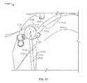
- FIG. 12is side view of a shoulder portion
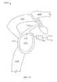
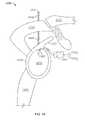
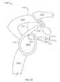
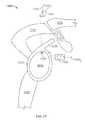
- FIG. 13 through FIG. 17are a sequence of views illustrating a SLAP repair using a suture transport according to a preferred embodiment of the present invention
- FIG. 13is a view subsequent to the FIG. 12 view in which a portal is installed into the shoulder segment with a suture anchor and attached suture strand secured into the shoulder through the portal;
- FIG. 14is a view subsequent to the FIG. 13 view in which a percutaneous delivery system has pierced through a skin portion and passed into an interior of the shoulder portion at the desired location while defining a desired suture path through the desired tissue components;
- FIG. 15is a view subsequent to the FIG. 14 view in which a suture transport is delivered from the distal end of the percutaneous delivery system at the desired location;
- FIG. 16is a view subsequent to the FIG. 15 view in which the suture transport is extracted out of the shoulder portion through the portal while the delivery system is retracted;
- FIG. 17is a view subsequent to the FIG. 16 view in which the suture transport has retracted one of the suture strands through the portal and through the suture path defined by the percutaneous delivery system;
- FIG. 18is a side plan view of a first preferred embodiment for an aperture portion of a suture transport.
- FIG. 19is a side plan view of a second preferred embodiment for an aperture portion of a suture transport.
- FIG. 1is a suture transport 100 adapted for percutaneous use according to an embodiment of the present invention.
- Transport 100includes a member 105 of a rigid flexible elastic material, member 105 including a body portion 110 and an aperture portion 115 .
- Member 105is adapted for delivery through an axial longitudinal channel of a percutaneous delivery subsystem (e.g., an 18 gauge or smaller spinal needle or other skin-piercing delivery system, or the like), with aperture portion 115 including an expanded mode (as shown in FIG. 1 ) having a lateral dimension (L) greater than an inner diameter of the channel when aperture portion 115 extends outside the channel.
- the collapsed modeshown, for example, in FIG.
- Aperture portion 115includes, in the preferred embodiment, a leader element 120 used to load/guide aperture portion 115 into the channel.
- Leader element 120may be omitted from some implementations, while in other implementations leader element 120 function is provided in a different manner, such as, for example, to help transition aperture portion 115 from the expanded mode to the collapsed mode, and/or, for example, to help load body member 105 into the channel of the percutaneous delivery subsystem, such as the spinal needle.
- TABLE I belowprovides Nominal outside diameter, nominal inside diameter, and nominal wall thicknesses for the specified needle gauge.
- body portion 105is constructed of a single monofilament of rigid memory material (e.g., NitinolTM other memory material including other metals or polymers, and the like) wound to produce body portion 110 , aperture portion 115 , and any leader element 120 .
- Body portion 105including aperture portion 115 in the collapsed mode, is constructed so it passes through an 18 gauge spinal/syringe needle, or smaller diameter needle (larger gauge number).
- Body portion 105is sufficiently rigid to be able to be pushed/pulled through the needle channel, and sufficiently elastic that aperture portion 115 repeatedly transitions between the expanded mode and the collapsed mode, permitting multiple uses of one suture transport 100 .
- suture transport 100is sufficiently rigid and elastic as described above, alternative constructions may be possible. For example, it may not be necessary to use a superelastic material for construction of body 105 , as in some cases a precursor alloy may be sufficient. In other instances, a multi-stranded structure may be used in some implementations.
- aperture portion 115transitions from the expanded mode to the collapsed mode when inserted into either of the channel openings and aperture portion 115 transitions from the collapsed mode to the expanded mode when exiting from any of the channel openings.
- Suture transport 100is constructed in such a way that it may be loaded from either end of the channel (e.g., the spinal needle) by inserting either body portion 110 or aperture portion 115 .
- Many conventional systemsinclude a handle or other structure that prevents such bi-directional, multi-option loading.
- Suture transport 100 of FIG. 1is specifically constructed without a handle or other structure permitting it to pass entirely through a channel from either end to the other, irrespective of which “end” of suture transport 100 is inserted into which end of the channel.
- FIG. 2is a first alternate embodiment of a suture transport 200 .
- Suture transport 200includes a handle 205 coupled to the proximal end of body member 105 shown in FIG. 1 . While handle 205 inhibits two-way and “either end” loading of suture transport 200 into the percutaneous delivery system, suture transport 200 is beneficial by addition of the handle as that may, in some instances, permit easier insertion or retraction through the channel and/or through tissue of the body, such as for example, enabling easier application of greater axial forces to body member 105 . In other respects, suture transport 200 corresponds closely to suture transport shown in FIG. 1 in construction, use, and operation.
- FIG. 3is a second alternate embodiment of a suture transport 300 .
- Suture transport 300includes a second aperture portion 305 coupled to the proximal end of body member 105 shown in FIG. 1 .
- Second aperture portion 305includes a leader element 310 and also includes an expanded mode with lateral dimension L and a collapsed mode for passage through the channel of percutaneous delivery system.
- Suture transport 300permits flexibility in moving sutures or other elements bi-directionally (e.g., it duplicates a sewing motion by eliminating a step, having aperture portions at both ends). In other respects, suture transport 300 corresponds closely to suture transport shown in FIG. 1 in construction, use, and operation.
- FIG. 4is a third alternate embodiment of a suture transport 400 .
- Transport 400includes a member 405 of a rigid flexible elastic material, member 405 including a first body portion 410 , an aperture portion 415 , and second body portion 420 , aperture portion 415 disposed between the body portions.
- Member 405is adapted for delivery through an axial longitudinal channel of a percutaneous delivery subsystem (e.g., an 18 gauge or smaller spinal needle or other skin-piercing delivery system, or the like), with aperture portion 415 including an expanded mode (as shown in FIG. 4 ) having a lateral dimension (L) greater than an inner diameter of the channel when aperture portion 415 extends outside the channel.
- a percutaneous delivery subsysteme.g., an 18 gauge or smaller spinal needle or other skin-piercing delivery system, or the like
- aperture portion 415including an expanded mode (as shown in FIG. 4 ) having a lateral dimension (L) greater than an inner diameter of the channel when aperture portion 415 extends outside the
- FIG. 5 and FIG. 6are a sequence of figures illustrating a percutaneous delivery subsystem 500 piercing a portion of a human body 505 (e.g., a shoulder) to deliver one of the suture transports (e.g., transport 100 of FIG. 1 ) described herein.
- a percutaneous delivery subsystem 500piercing a portion of a human body 505 (e.g., a shoulder) to deliver one of the suture transports (e.g., transport 100 of FIG. 1 ) described herein.
- FIG. 5illustrates suture transport 100 shown in FIG. 1 used with subsystem 500 .
- subsystem 500includes an 18 gauge or smaller diameter spinal needle having a channel 510 .
- Subsystem 500is used to deliver the distal end within body 505 to the proper location, including definition of a prospective suture path through various tissue elements within body 505 .
- subsystem 500may additionally pierce internal tendons, ligaments, and other tissue so that when a suture is captured by the aperture portion and the transport is extended or retracted, the suture also passes through the pierced intermediate tissue elements at the location(s) and in the order defined by subsystem 500 .
- subsystem 500may deliver the distal end to practically any location, through many different types of tissue from virtually any angle or orientation, an operator has almost unlimited options when defining and implementing the optimum suture path and ingress/egress location from body 505 . As shown (and as described above) aperture portion 115 is in the collapsed mode when within channel 510 .
- FIG. 6illustrates suture transport 100 extending outside channel 510 with aperture portion 115 transitioned to the expanded mode.
- aperture portion 115automatically transitions from the collapsed mode shown in FIG. 5 to the expanded mode shown in FIG. 6 when exiting from the distal end of channel 510 because of the construction and configuration of the transports as described herein.
- subsystem 500may be withdrawn from body 505 , leaving transport 100 in place. Thus, a suture need not pass through delivery subsystem 500 when exiting body 505 .
- FIG. 7 through FIG. 10are a detailed sequence of figures illustrating results of use of a percutaneous delivery subsystem piercing a portion of a human body (e.g., a shoulder) to deliver one of the suture transports (e.g., the transport of FIG. 1 ) described herein;
- FIG. 7illustrates a portion of a shoulder 700 including installation of a suture anchor 705 into a bone of the shoulder near a desired location for a repair of a capsular tissue portion 710 , suture anchor 705 including four suture strands 715 n .
- Suture anchor 705is installed through a first portal 720 and a first suture strand 7151 is retrieved through a second portal 735 .
- a gripper, forceps, or other arthroscopic tool/accessorymay be used to retrieve a suture strand 715 x through second portal 725 .
- FIG. 8illustrates the portion of shoulder 700 shown in FIG. 7 after a percutaneous delivery system 730 pierces both the skin of shoulder 700 and capsular tissue 710 at an optimum location and delivers a shuttle transport 735 including aperture portion 740 through the skin and capsular tissue 710 . Additionally, aperture portion 740 has been retrieved through second portal 725 in the same or similar manner as suture strand 7151 was retrieved. Suture strand 7151 is threaded through aperture portion 740 while aperture 740 extends outside shoulder 700 through second portal 725 .
- FIG. 9illustrates the portion of shoulder 700 shown in FIG. 7 and FIG. 8 after shuttle transport 735 is withdrawn through the channel of percutaneous delivery system 730 while system 730 remains partially within shoulder 700 but withdrawn from capsular tissue 710 .
- Thisdemonstrates another feature of the preferred embodiments, namely that the distal end of percutaneous delivery system 730 may be progressively advanced or withdrawn to aid in movement of suture transport 735 within shoulder 700 and the portals and preferred suture installation path(s).
- the distal end of percutaneous delivery system 730may aid in directing suture transport 735 during its movement.
- the distalmay remain positioned through capsular tissue 710 as suture transport (along with suture strand 7151 ) is withdrawn back into second portal 725 towards the exit point of the distal end through capsular tissue 710 .
- the distal end of system 730may be withdrawn from capsular tissue 710 and then suture transport 735 withdrawn through capsular tissue 710 where the distal end passed through.
- Withdrawing suture transport 735 through capsular tissue 710also pulls suture strand 7151 through capsular tissue 710 along the path defined by delivery system 730 as suture strand 7151 is threaded through aperture 740 .
- the embodiments of the present inventionprovide this flexibility.
- FIG. 10illustrates the portion of shoulder 700 shown in FIG. 7 , FIG. 8 , and FIG. 9 after shuttle transport 735 is completely withdrawn through shoulder 700 with suture strand 7151 extending from an aperture 1000 defined by the exiting percutaneous delivery system 730 shown in FIG. 7 , FIG. 8 , and FIG. 9 .
- Suture strand 7151is thus accurately located, positioned, and installed at the appropriate locations in capsular tissue 710 and through aperture 1000 .
- FIG. 11is an external view of the portion of a body 1100 (e.g., a shoulder segment) after optimum placement of multiple suture strands 1115 n using one or more suture transports described herein in cooperation with a first portal 1120 and a second portal 1125 as described herein.
- FIG. 11illustrates some of the advantages of the present invention including 360° suture strand 1115 placement with minimum use of portals. With the two portals shown, it is noted that suture strand 1115 placement is not limited to locations between the two portals, nor within a narrow angular range.
- tissuetendons, ligaments, other cartilage or tissue or the like
- tissueto be stabilized may be accessed at virtually any location from virtually any direction and any part of the body portion similarly may be pierced from virtually any direction providing great flexibility in installing one or more suture strands in the optimum number, locations, and directions.
- the preparation for this arthroscopic repair of a shoulderbegins by installing a suture anchor (e.g., in a portion of bone), at a point where a portion of capsular tissue is desired to be fixed. Initially, some number of strands of suture material attached to the suture anchor is passed through a first portal with the anchor prior to installation. Each strand is passed through the portion of the capsular tissue.
- a suture anchore.g., in a portion of bone
- suture strandsmay be installed in multiple discrete steps (e.g., successive retrieval of the suture strand in two stages—first through the capsular tissue and then second through the skin covering the shoulder portion).
- the embodiments of the present inventionoptionally provides for such multiple stages to be achieved in a single integrated step. That is, a percutaneous delivery system pierces the shoulder and the capsular tissue in one step and delivers the distal end of the delivery system proximate the suture anchor, once for each suture strand.
- the suture transportis passed through the channel of the delivery system so that the aperture portion is available to be loaded with the suture strand in question.
- the delivery systemis retracted, and then the suture transport delivers the suture strand through the capsular tissue and the shoulder when retracted.
- the present inventionpermits use of the two stage when necessary or desirable by first locating each suture strand appropriately through the capsular tissue and then, later, retrieving each strand through the shoulder.
- the present inventionprovides a great degree of flexibility, not just with locating and delivering a suture strand, but also in combining or separating steps of many arthroscopic procedures used for tissue stabilization.
- Each suture strandis passed through a portion of the skin of a body part, such as for example a shoulder, each suture strand accurately, independently, and optimally installed with a minimal number of portals installed. At this point, arthroscopic knots are tied and advanced in the normal fashion.
- the present inventionmay be used in a number of surgical procedures involved with tissue tying (e.g., arthroscopic and open surgeries), such as rotator cuff repair or shoulder instability repair among other types of procedures in which cartilage (tendons, ligaments, and the like) and other tissue are stabilized and secured.
- tissue tyinge.g., arthroscopic and open surgeries
- rotator cuff repair or shoulder instability repairamong other types of procedures in which cartilage (tendons, ligaments, and the like) and other tissue are stabilized and secured.
- FIG. 12is side view of a shoulder 1200 .
- shoulder 1200is a ball and socket joint.
- An upper part of a humerus 1205includes a ball that fits into a socket portion of a scapula called a glenoid 1210 .
- Shoulder 1200is made up of three bones: the scapula (shoulder blade), humerus 1205 (upper arm bone) and a clavicle (collarbone) 1215 .
- a part of the scapula that makes up the roof of the shoulderis called an acromion 1220 .
- a rotator cuffis responsible for the motion, stability, and power of humerus 1205 .
- a joint where acromion 1220 and clavicle 1215 join togetheris known as an acromioclavicular (AC) joint.
- ACacromioclavicular
- ligamentsthat provide stability to this joint.
- the true shoulder jointis called a glenohumeral joint and is formed by humerus (upper arm) 1205 and a glenoid labrum 1225 of the scapula (shoulder blade).
- the relative size of these two structuresis analogous to a golf ball (head of the humerus) on a golf tee (glenoid).
- One type of injuryis the SLAP lesion.
- Labrum 1225deepens the golf tee to help make the shoulder more stable.
- a biceps tendon 1230attaches at the top of labrum 1225 . This is the area of the SLAP lesion.
- SLAPis an acronym for Superior Labrum Anterior to Posterior. This describes the way the labrum tears.
- the glenohumeral joint, subacromial space and proposed portalsare injected with a combination of lidocaine and Marcaine with epinephrine after attempting to aspirate prior to injecting.
- a standard posterior portalis opened using a #15 blade taking care to place the incisions in the Langer lines.
- a blunt obturatoris used to enter the shoulder.
- the 4 mm 30 degree arthroscopeis placed in the shoulder and an anterior portal is opened using inside-out technique. A thorough diagnostic arthroscopy is performed.
- a lateral portalis not necessary for this type of repair.
- the posterior portalis used for viewing and the anterior portal is the working portal.
- the superior labral tearis identified.
- the glenoidis cleaned down to bleeding cortical bone using an arthroscopic elevator, rasp and a motorized shaver.
- An arthroscopic awlis frequently used to assure a good bleeding surface.
- a drill guideis brought in to the glenohumeral joint through the anterior portal, passed medial to the long head of the biceps tendon and placed on the posterosuperior glenoid at a 45° angle.
- the drillis placed and bottomed out on the guide and removed.
- an anchoris placed and tapped into position until the handle bottoms out on the guide. Multiple counterclockwise turns are performed with the handle to allow the insertor to be removed.
- the suture endsare smartly tugged to set the anchor.
- An 18 gauge spinal needleis brought into the shoulder percutaneously adjacent to the lateral acromion. It is seen to enter the shoulder through the supraspinatus tendon.
- the transportis then introduced through the needle until it enters the glenohumeral joint.
- a grasperis used to capture the transport and it is withdrawn through the anterior cannula.
- the needleis then pulled back through the skin.
- the two suture endsare passed through the loop end (aperture portion) of the transport and the transport is removed leaving the suture exiting through the skin.
- the suture end closest to the labrumis pulled back through the anterior cannula using a grasper.
- the spinal needleis seen to enter the shoulder behind the biceps tendon.
- an arthroscopic probecan be used to pull the capsule medially for better visualization.
- the spinal needleis directed under the labrum and seen to exit between the labrum and the glenoid.
- the transportis introduced through the needle and withdrawn through the anterior cannula.
- the spinal needleis backed out through the skin.
- the suture limbis passed through the loop end and the transport is withdrawn leaving the suture through the skin. This is the post for tying.
- the 2 suture limbsare captured and pulled out through the anterior cannula with both limbs passing medial to the biceps tendon.
- the suturesare tied using a sliding knot followed by half hitches. The excess sutures are cut using an arthroscopic knot cutter.
- An anterosuperior anchoris then placed.
- the suture endsare again withdrawn in a percutaneous manner laterally.
- the post sutureis retrieved through the anterior cannula.
- the spinal needleis brought into the shoulder through the subclavicular region. This is just medial and superior to the anterior cannula.
- the transportis introduced and brought out through the anterior cannula and the needle is backed out of the skin.
- the post suture limbis passed. Both suture limbs are captured and brought out through the anterior cannula.
- the suturesare tied and cut. The integrity of the repair is assessed.
- FIG. 13 through FIG. 17are a sequence of views illustrating portions of the SLAP repair described above using a suture transport according to a preferred embodiment of the present invention.
- FIG. 13is a view subsequent to the FIG. 12 view in which a portal 1300 is installed into shoulder 1200 with a suture anchor 1305 and attached suture strands 1310 secured into the posterosuperior glenoid 1210 at the 45° angle.
- FIG. 14is a view subsequent to the FIG. 13 view in which a percutaneous delivery system 1400 for a suture transport 1405 has pierced through a skin portion 1410 and passed into an interior of the shoulder portion adjacent to the lateral acromion while defining a desired suture path through the desired tissue components (for example in this case, from skin portion 1410 through the supraspinatus tendon).
- FIG. 15is a view subsequent to the FIG. 14 view in which an aperture portion 1500 of suture transport 1405 is delivered from the distal end of percutaneous delivery system 1400 at the desired location (for example, into the glenohumeral joint).
- FIG. 16is a view subsequent to the FIG. 15 view in which suture transport 1405 is extracted out of shoulder 1200 through portal 1300 while the delivery system is retracted.
- FIG. 17is a view subsequent to the FIG. 16 view in which the suture transport has retracted one of the suture strands through the portal and through the suture path defined by the percutaneous delivery system.
- the two suture endswere passed through the loop end (aperture portion 1500 ) of suture transport 1405 and transport 1405 was removed leaving suture 13101 exiting through the skin.
- the suture end closest to labrum 1225is pulled back through the anterior cannula (portal 1300 ) using a grasper.
- FIG. 18is a side plan view of a first preferred embodiment for aperture portion 115 of a suture transport described herein.
- nis equal to 6 (first embodiment FIG. 18 ) or n is equal to 8 (second embodiment FIG. 19 ) then a desirable configuration for aperture portion 115 is achieved as further explained below.
- FIG. 19is a side plan view of a second preferred embodiment for aperture portion 115 of a suture transport including an aperture extending portion 1900 inserted between each of two pairs of angles of the embodiment shown in FIG. 18 to produce a generalized elongated hexagon shape.
- nmay vary but is generally an even number that is 6 or greater (6 and 8 being the preferred values), though other configurations are possible.
- leader 1805is depicted schematically as leader 1805 in FIG. 18 and FIG. 19 .
- the preferred embodimentincludes a short twist to end portion 1805 (not shown for clarity) which may be one or more twists in length. In general for many applications it is desirable to have leader 1805 be less than three twists, and most preferably a single twist or a portion of a complete twist.
- Leader 1805joins aperture portion 115 at a pair of bends.
- Body portion 110(not shown in FIG. 18 and FIG. 19 ) also joins aperture portion 115 at a second pair of bends.
- the configuration of the angles as described by this embodiment with hard angles joined at the twistsimproves the opening and closing of aperture portion 115 to increase reliability and improve the size of the enclosed area of the loop. It, along with use of non-shearing cross-sectional profiles of the filaments, also enables the expansion and contraction of aperture portion 115 to be implemented by a scissoring action to form a scissor trap.
- a very large pull forceis applied to transport 100 and it is desirable to trap reliably a suture within aperture portion 115 .
- the hard angles, particularly those proximate leader portion 1805assist in retaining the suture within aperture portion 115 while pulling, particularly while applying relatively large pull forces that may exceed a hundred foot-pounds.
- This scissor trapmakes it possible to very securely grip the suture and enabling relatively large pull forces that may equal or exceed 500 foot-pounds of pulling force. Maintaining the engagement of the scissor trap is achieved by the relative location of the transport within the channel. In some instances, leader portion 1805 may have a different configuration to improve trapping for pulling.
- aperture portion 115be of a single monofilament of shape memory material sized to fit a twisted strand within the channel; in contrast to a twisted braided multi-filament.
- One potential drawback of braided multi-filament used in aperture portion 115is that it is very difficult to exactly match lengths properly resulting in uneven load distributions that may cause cascading failures of the individual filaments, thus causing the entire aperture portion 115 to fail.
- transport 100is sized for the inner dimensions of this sheath.
- the percutaneous delivery subsystemis a skin-piercing/puncturing system different from systems and methods that make an incision to form all or part of the portal or opening, including those that insert cannulas, and most preferably provide a pair of openings—one exterior to the body and one interior proximate a desired delivery point.
- These non-piercing/non-puncturing systemsare more traumatic to the tissue than insertion of a small gauge (e.g., 18 gauge or smaller diameter).
- the fine gaugepermits precise and simple placement of a suture at virtually any location.
- the percutaneous delivery subsystem and transportmay be used for multistage suture path definition or discrete definition of suture path segments, at the option of the operator in any specific case.
- the embodimentsare simple and efficient, applicable to many situations and implementations.
- any signal arrows in the drawings/ Figuresshould be considered only as exemplary, and not limiting, unless otherwise specifically noted.
- the term “or” as used hereinis generally intended to mean “and/or” unless otherwise indicated. Combinations of components or steps will also be considered as being noted, where terminology is foreseen as rendering the ability to separate or combine is unclear.
Landscapes
- Health & Medical Sciences (AREA)
- Life Sciences & Earth Sciences (AREA)
- Surgery (AREA)
- Heart & Thoracic Surgery (AREA)
- Engineering & Computer Science (AREA)
- Biomedical Technology (AREA)
- Nuclear Medicine, Radiotherapy & Molecular Imaging (AREA)
- Medical Informatics (AREA)
- Molecular Biology (AREA)
- Animal Behavior & Ethology (AREA)
- General Health & Medical Sciences (AREA)
- Public Health (AREA)
- Veterinary Medicine (AREA)
- Rheumatology (AREA)
- Surgical Instruments (AREA)
Abstract
Description
| TABLE I |
| Syringe Needle Dimensions |
| Nominal OD | Nominal ID | Nominal Wall Thickness | |
| Needle Gauge | (inches) | (inches) | (inches) |
| 17 | .0580 | .0420 | .0080 |
| 18 | .0500 | .0330 | .0080 |
| 19 | .0420 | .0270 | .0075 |
Claims (7)
Priority Applications (1)
| Application Number | Priority Date | Filing Date | Title |
|---|---|---|---|
| US12/983,325US8282658B2 (en) | 2006-10-05 | 2011-01-02 | Shape memory filament for suture management |
Applications Claiming Priority (2)
| Application Number | Priority Date | Filing Date | Title |
|---|---|---|---|
| US11/309,830US9072514B2 (en) | 2006-10-05 | 2006-10-05 | Shape memory filament for suture management |
| US12/983,325US8282658B2 (en) | 2006-10-05 | 2011-01-02 | Shape memory filament for suture management |
Related Parent Applications (1)
| Application Number | Title | Priority Date | Filing Date |
|---|---|---|---|
| US11/309,830DivisionUS9072514B2 (en) | 2006-10-05 | 2006-10-05 | Shape memory filament for suture management |
Publications (2)
| Publication Number | Publication Date |
|---|---|
| US20110098742A1 US20110098742A1 (en) | 2011-04-28 |
| US8282658B2true US8282658B2 (en) | 2012-10-09 |
Family
ID=39275582
Family Applications (4)
| Application Number | Title | Priority Date | Filing Date |
|---|---|---|---|
| US11/309,830Active2029-04-16US9072514B2 (en) | 2006-10-05 | 2006-10-05 | Shape memory filament for suture management |
| US12/983,325Active - Reinstated2026-10-08US8282658B2 (en) | 2006-10-05 | 2011-01-02 | Shape memory filament for suture management |
| US14/726,589Active2027-08-13US9999420B2 (en) | 2006-10-05 | 2015-05-31 | Shape memory filament for suture management |
| US16/010,482Active2027-01-02US10869661B2 (en) | 2006-10-05 | 2018-06-17 | Shape memory filament for suture management |
Family Applications Before (1)
| Application Number | Title | Priority Date | Filing Date |
|---|---|---|---|
| US11/309,830Active2029-04-16US9072514B2 (en) | 2006-10-05 | 2006-10-05 | Shape memory filament for suture management |
Family Applications After (2)
| Application Number | Title | Priority Date | Filing Date |
|---|---|---|---|
| US14/726,589Active2027-08-13US9999420B2 (en) | 2006-10-05 | 2015-05-31 | Shape memory filament for suture management |
| US16/010,482Active2027-01-02US10869661B2 (en) | 2006-10-05 | 2018-06-17 | Shape memory filament for suture management |
Country Status (8)
| Country | Link |
|---|---|
| US (4) | US9072514B2 (en) |
| EP (1) | EP2059177B1 (en) |
| JP (1) | JP5357035B2 (en) |
| CN (1) | CN101631503B (en) |
| AU (1) | AU2007308005B2 (en) |
| BR (1) | BRPI0718082A2 (en) |
| CA (1) | CA2662681C (en) |
| WO (1) | WO2008045683A1 (en) |
Cited By (7)
| Publication number | Priority date | Publication date | Assignee | Title |
|---|---|---|---|---|
| US20080086147A1 (en)* | 2006-10-05 | 2008-04-10 | Knapp Thomas P | Shape memory filament for suture management |
| US9204888B2 (en) | 2007-06-08 | 2015-12-08 | United States Endoscopy Group, Inc. | Retrieval device |
| US9486188B2 (en) | 2001-05-18 | 2016-11-08 | United States Endoscopy Group, Inc. | Retrieval device |
| US9572591B2 (en) | 2013-09-03 | 2017-02-21 | United States Endoscopy Group, Inc. | Endoscopic snare device |
| US9872700B2 (en) | 2013-09-03 | 2018-01-23 | United States Endoscopy Group, Inc. | Endoscopic snare device |
| US9999420B2 (en) | 2006-10-05 | 2018-06-19 | Depuy Mitek, Llc | Shape memory filament for suture management |
| US10667838B2 (en) | 2017-01-09 | 2020-06-02 | United States Endoscopy Group, Inc. | Endoscopic snare device |
Families Citing this family (8)
| Publication number | Priority date | Publication date | Assignee | Title |
|---|---|---|---|---|
| US20090036905A1 (en)* | 2007-01-30 | 2009-02-05 | Reinhold Schmieding | Method of tissue fixation using cinch stitching |
| US20110087248A1 (en)* | 2009-10-14 | 2011-04-14 | Steffen Dennis L | Flexor Tendon Suture Passer |
| FR2962026B1 (en)* | 2010-07-02 | 2013-04-26 | Tornier Inc | SYSTEM FOR SUTURE |
| DE102014208168A1 (en) | 2014-04-30 | 2015-11-19 | Epflex Feinwerktechnik Gmbh | Fangkelinstrument with distal Fangkelchstruktur |
| DE102015121818A1 (en)* | 2015-12-15 | 2017-06-22 | Biotronik Se & Co. Kg | Implementation of a medical electronic device, method for producing such and medical electronic device |
| CN106725675A (en)* | 2016-12-20 | 2017-05-31 | 马强 | A kind of memorial alloy suture and preparation method for being loaded with growth factor |
| US11350923B2 (en)* | 2018-06-04 | 2022-06-07 | Arthrex, Inc. | Surgical constructs with shuttling loops and methods of tissue fixation |
| KR102200244B1 (en)* | 2019-11-08 | 2021-01-08 | 후지코교 가부시기가이샤 | Fishing line threader, and method of manufacturing fishing line threader |
Citations (84)
| Publication number | Priority date | Publication date | Assignee | Title |
|---|---|---|---|---|
| US2054149A (en) | 1935-03-25 | 1936-09-15 | Wappler Frederick Charles | Surgical snare |
| GB792678A (en) | 1955-01-14 | 1958-04-02 | Leo Markoff Moghadam | Fast threading needle with trailing flexible link |
| US3791387A (en) | 1970-12-05 | 1974-02-12 | Olympus Optical Co | Forceps |
| US3805791A (en) | 1971-07-01 | 1974-04-23 | K Seuberth | Apparatus for the diathermic removal of growths |
| US3828790A (en) | 1973-02-28 | 1974-08-13 | American Cystoscope Makers Inc | Surgical snare |
| US4102478A (en)* | 1976-12-27 | 1978-07-25 | Constantin Samoilov | Needle threader |
| US4133339A (en)* | 1975-07-11 | 1979-01-09 | Floss Aid Corporation | Needle with deformable eye |
| US4326530A (en) | 1980-03-05 | 1982-04-27 | Fleury Jr George J | Surgical snare |
| US4347846A (en) | 1979-12-07 | 1982-09-07 | Porges | Surgical extractor |
| US4641652A (en) | 1984-04-12 | 1987-02-10 | Richard Wolf Gmbh | Applicator for tying sewing threads |
| US4779616A (en) | 1986-02-04 | 1988-10-25 | Johnson Lanny L | Surgical suture-snagging method |
| US5084054A (en) | 1990-03-05 | 1992-01-28 | C.R. Bard, Inc. | Surgical gripping instrument |
| US5100418A (en) | 1987-05-14 | 1992-03-31 | Inbae Yoon | Suture tie device system and applicator therefor |
| US5251797A (en)* | 1992-01-22 | 1993-10-12 | Martin Glenn A | Eyelet threading aid |
| US5281237A (en)* | 1992-09-25 | 1994-01-25 | Gimpelson Richard J | Surgical stitching device and method of use |
| US5454834A (en) | 1992-03-12 | 1995-10-03 | Richard Wolf Gmbh | Surgical suture material |
| US5496330A (en) | 1993-02-19 | 1996-03-05 | Boston Scientific Corporation | Surgical extractor with closely angularly spaced individual filaments |
| US5499991A (en)* | 1994-12-19 | 1996-03-19 | Linvatec Corporation | Endoscopic needle with suture retriever |
| US5501692A (en)* | 1994-01-28 | 1996-03-26 | Riza; Erol D. | Laparoscopic suture snare |
| US5522819A (en) | 1994-05-12 | 1996-06-04 | Target Therapeutics, Inc. | Dual coil medical retrieval device |
| US5561973A (en) | 1991-09-30 | 1996-10-08 | St. Germain; Dennis | Flexible sling construction reinforced by eye parts extended in opposite longitudinal direction throughout multiple body parts in reverse rotational interwine |
| US5573530A (en) | 1994-12-15 | 1996-11-12 | Cabot Technology Corporation | Handle for a surgical instrument including a manually actuated brake |
| US5618290A (en)* | 1993-10-19 | 1997-04-08 | W.L. Gore & Associates, Inc. | Endoscopic suture passer and method |
| US5628756A (en) | 1993-01-06 | 1997-05-13 | Smith & Nephew Richards Inc. | Knotted cable attachment apparatus formed of braided polymeric fibers |
| US5643292A (en)* | 1995-01-10 | 1997-07-01 | Applied Medical Resources Corporation | Percutaneous suturing device |
| US5722981A (en) | 1993-10-08 | 1998-03-03 | Tahoe Surgical Instruments | Double needle ligature device |
| US5755728A (en)* | 1996-03-07 | 1998-05-26 | Maki; Neil J. | Suture apparatus with loop end portions |
| US5836955A (en) | 1995-07-14 | 1998-11-17 | C.R. Bard, Inc. | Wound closure apparatus and method |
| US5895395A (en) | 1997-07-17 | 1999-04-20 | Yeung; Teresa T. | Partial to full thickness suture device & method for endoscopic surgeries |
| US5906624A (en)* | 1997-01-03 | 1999-05-25 | Mitek Surgical Products, Inc. | Suture threader assembly, suture anchor assembly, and method for threading suture |
| US5947979A (en) | 1997-08-07 | 1999-09-07 | Asahi Kogaku Kogyo Kabushiki Kaisha | Wire loop type instrument for endoscope and method of producing the same |
| US5976073A (en) | 1997-06-18 | 1999-11-02 | Asahi Kogaku Kogyo Kabushiki Kaisha | Hood of endoscope |
| US6013086A (en) | 1997-08-28 | 2000-01-11 | Asahi Kogaku Kogyo Kabushiki Kaisha | Wire loop type instrument for endoscope |
| US6015381A (en) | 1997-01-17 | 2000-01-18 | Asahi Kogaku Kogyo Kaisha | Endoscopic treatment tool |
| US6022360A (en)* | 1997-08-06 | 2000-02-08 | Ethicon, Inc. | Suture retrograder |
| US6090129A (en) | 1996-06-11 | 2000-07-18 | Asahi Kogaku Kogyo Kabushiki Kaisha | Treatment accessory for endoscope |
| US6093195A (en) | 1998-08-17 | 2000-07-25 | Asahi Kogaku Kogyo Kabushiki Kaisha | Endoscopic treatment tool |
| US6132440A (en) | 1992-10-19 | 2000-10-17 | Advanced Research & Technology Institute | Apparatus and method for positive closure of an internal tissue membrane opening |
| US6136010A (en) | 1999-03-04 | 2000-10-24 | Perclose, Inc. | Articulating suturing device and method |
| US6143017A (en) | 1999-03-17 | 2000-11-07 | Thal; Raymond | Free loop knotless suture anchor assembly |
| US6152922A (en) | 1998-07-27 | 2000-11-28 | Asahi Kogaku Kogyo Kabushiki Kaisha | High-frequency snare for endoscope |
| US6187017B1 (en) | 1998-02-17 | 2001-02-13 | Circon Corporation | Retrieval basket for a surgical device |
| US6217589B1 (en) | 1999-10-27 | 2001-04-17 | Scimed Life Systems, Inc. | Retrieval device made of precursor alloy cable and method of manufacturing |
| US6224611B1 (en) | 1998-09-14 | 2001-05-01 | Asahi Kogaku Kogyo Kabushiki Kaisha | Snare for endoscope |
| US6245078B1 (en) | 1999-04-26 | 2001-06-12 | Asahi Kogaku Kogyo Kabushiki Kaisha | Snare for endoscope |
| US20010012945A1 (en) | 1998-06-08 | 2001-08-09 | Romano Jack W. | Method and apparatus for deploying a memory working tip member to or from an approach path to a desired working area |
| US6299612B1 (en) | 1998-09-02 | 2001-10-09 | Asahi Kogaku Kogyo Kabushiki Kaisha | Wire loop type instrument for endoscope and method of producing the same |
| US6423054B1 (en) | 1999-08-04 | 2002-07-23 | Asahi Kogaku Kogyo Kabushiki Kaisha | Operation wire connecting part in endoscopic treating instrument |
| US6423060B1 (en) | 1999-01-07 | 2002-07-23 | Asahi Kogaku Kogyo Kabushiki Kaisha | High-frequency instrument for endoscope |
| US20020107530A1 (en) | 2001-02-02 | 2002-08-08 | Sauer Jude S. | System for endoscopic suturing |
| US20020107526A1 (en) | 2000-11-03 | 2002-08-08 | Cook Incorporated | Medical grasping device |
| US6471690B1 (en) | 1999-08-04 | 2002-10-29 | Asahi Kogaku Kogyo Kabushiki Kaisha | Connecting part in endoscopic treating instrument |
| US6475229B1 (en) | 2000-05-15 | 2002-11-05 | Ancel Surgical R&D, Inc. | Moldable crimpable suture thread and method for making same |
| US20020165555A1 (en) | 2001-04-05 | 2002-11-07 | Stein Barry L. | Shape memory surgical polypectomy tool |
| US6517551B1 (en) | 2000-11-22 | 2003-02-11 | George Mark Driskill | Intravascular foreign object retrieval catheter |
| US6517539B1 (en) | 1999-08-06 | 2003-02-11 | Scimed Life Systems, Inc. | Polypectomy snare having ability to actuate through tortuous path |
| US6554845B1 (en) | 2000-09-15 | 2003-04-29 | PARÉ Surgical, Inc. | Suturing apparatus and method |
| US6605096B1 (en) | 2001-07-20 | 2003-08-12 | Opus Medical Inc, | Percutaneous suturing apparatus and method |
| US6629984B1 (en) | 1998-07-07 | 2003-10-07 | Kwan-Ho Chan | Surgical repair kit and its method of use |
| US20030236535A1 (en)* | 2002-05-08 | 2003-12-25 | Olympus Optical Co., Ltd. | Apparatus for ligating/suturing living tissues and system for resecting/suturing living tissues |
| US20040010273A1 (en)* | 2001-02-26 | 2004-01-15 | Diduch David R. | Superelastic suture passing devices and methods |
| US6723107B1 (en)* | 1999-04-19 | 2004-04-20 | Orthopaedic Biosystems Ltd. | Method and apparatus for suturing |
| US20040097975A1 (en)* | 2002-08-26 | 2004-05-20 | Rose Donald J. | Nitinol loop suture passer |
| US20040127915A1 (en) | 2002-12-30 | 2004-07-01 | Fleenor Richard P. | Suture hoop system |
| US6761717B2 (en) | 1999-10-15 | 2004-07-13 | Scimed Life Systems, Inc. | Multifilar flexible rotary shaft and medical instruments incorporating the same |
| US20040236353A1 (en) | 2002-06-26 | 2004-11-25 | Opus Medical, Inc. | Suture capture device |
| US20050033365A1 (en) | 2003-07-10 | 2005-02-10 | Olivier Courage | Cannulated instrument with curved shaft for passing suture through tissue |
| US20050038449A1 (en) | 1999-11-05 | 2005-02-17 | Sancoff Gregory E. | Apparatus and method for placing suture wires into tissue for the approximation and tensioning of tissue |
| US20050043746A1 (en) | 2003-08-21 | 2005-02-24 | Pollak Stanley B. | Methods and instruments for closing laparoscopic trocar puncture wounds |
| US6860887B1 (en) | 2001-11-05 | 2005-03-01 | Mark A. Frankle | Suture management method and system |
| US20050065535A1 (en) | 2003-07-02 | 2005-03-24 | Morris John K. | Method and device for suture isolation |
| US20050096650A1 (en) | 2003-10-29 | 2005-05-05 | Pentax Corporation | Medical instrument for endoscope |
| US20050131424A1 (en) | 2003-12-10 | 2005-06-16 | Pentax Corporation | Endoscopic high-frequency snare |
| US6972017B2 (en) | 1999-08-06 | 2005-12-06 | Scimed Life Systems, Inc. | Polypectomy snare having ability to actuate through tortuous path |
| US20050277947A1 (en) | 2004-05-25 | 2005-12-15 | Dave Ziegler | Medical retrieval devices |
| WO2006023975A2 (en) | 2004-08-24 | 2006-03-02 | Depuy Mitek, Inc. | Expandable needle suture apparatus and associated handle assembly with rotational suture manipulation system |
| US20060067967A1 (en) | 2000-12-21 | 2006-03-30 | Depuy Mitek, Inc. | Reinforced foam implants with enhanced integrity for soft tissue repair and regeneration |
| US20080086147A1 (en) | 2006-10-05 | 2008-04-10 | Knapp Thomas P | Shape memory filament for suture management |
| US20080086171A1 (en) | 2006-10-05 | 2008-04-10 | Knapp Thomas P | Shape memory filament for suture management |
| US7402162B2 (en) | 2004-03-24 | 2008-07-22 | Hoya Corporation | High frequency treatment instrument for endoscope |
| US20080215064A1 (en) | 2006-09-22 | 2008-09-04 | Motosugi Shunsuke | Endoscopic treatment instrument |
| US7458973B2 (en) | 2004-09-06 | 2008-12-02 | Hoya Corporation | High-frequency snare for endoscope |
| US20090005792A1 (en) | 2005-03-17 | 2009-01-01 | Satoshi Miyamoto | Medical Suturing and Ligating Apparatus |
| US20090018554A1 (en) | 2007-07-12 | 2009-01-15 | Marc Thorne | Suture passing and retrieval device |
Family Cites Families (25)
| Publication number | Priority date | Publication date | Assignee | Title |
|---|---|---|---|---|
| US2167080A (en)* | 1936-05-26 | 1939-07-25 | William S Mason | Needle threader |
| US2567408A (en)* | 1945-05-23 | 1951-09-11 | Soderberg Gustav Evert | Needle threader |
| US2448432A (en)* | 1946-07-01 | 1948-08-31 | Huning Ruth | System of threading needles |
| US2716515A (en)* | 1955-01-14 | 1955-08-30 | Moghadam Leon Marcoff | Fast-threading needle with trailing flexible link |
| US4011658A (en)* | 1972-06-19 | 1977-03-15 | John O. Butler Company | Device for inserting dental floss through interproximal areas and method of using same |
| US3987839A (en)* | 1975-09-24 | 1976-10-26 | Pace Robert K | Needle apparatus and method for making needle apparatus |
| US4667860A (en)* | 1984-10-15 | 1987-05-26 | Feuerman Research & Development Corporation | Sewing needle with easy-threading filament loop |
| JPS62246478A (en) | 1986-04-17 | 1987-10-27 | Komatsubara Kenma Seisakusho:Kk | Wheel for polishing |
| JPH03295551A (en)* | 1990-04-12 | 1991-12-26 | Olympus Optical Co Ltd | High frequency treating implement |
| JPH0624533B2 (en) | 1990-12-29 | 1994-04-06 | 昌貴 鮒田 | Medical instruments |
| JP3295551B2 (en) | 1994-09-16 | 2002-06-24 | 富士写真フイルム株式会社 | Inspection element and cartridge for accommodating the element |
| JPH10277044A (en) | 1997-04-03 | 1998-10-20 | Yuichi Matsuzawa | Ligation of suture for medical operation |
| JPH119610A (en) | 1997-06-20 | 1999-01-19 | Asahi Optical Co Ltd | Endoscope cautery |
| JPH11114059A (en) | 1997-10-16 | 1999-04-27 | Asahi Optical Co Ltd | Endoscope treatment tool |
| US6245081B1 (en)* | 1998-01-09 | 2001-06-12 | Steven M. Bowman | Suture buttress |
| US6309374B1 (en)* | 1998-08-03 | 2001-10-30 | Insite Vision Incorporated | Injection apparatus and method of using same |
| US6077277A (en) | 1999-04-05 | 2000-06-20 | Starion Instruments, Inc. | Suture welding device |
| WO2000069342A2 (en)* | 1999-05-14 | 2000-11-23 | Sutura, Inc. | Surgical knot pusher |
| US6500184B1 (en) | 2001-01-31 | 2002-12-31 | Yung C. Chan | Suturing apparatus and method of suturing |
| JP4261814B2 (en)* | 2001-04-04 | 2009-04-30 | オリンパス株式会社 | Tissue puncture system |
| CN1303773C (en) | 2001-07-10 | 2007-03-07 | 皇家菲利浦电子有限公司 | Method of transmitting data packets |
| US6439000B1 (en)* | 2001-07-18 | 2002-08-27 | Anne A. Smark | Bead threading tool and method for crocheting, knitting and the like |
| PL223153B1 (en)* | 2002-09-18 | 2016-10-31 | Allergan Inc | Methods and apparatus for delivery of ocular implants |
| US8585714B2 (en) | 2003-03-18 | 2013-11-19 | Depuy Mitek, Llc | Expandable needle suture apparatus and associated handle assembly with rotational suture manipulation system |
| US20090277934A1 (en)* | 2008-05-12 | 2009-11-12 | Mrs. Jane F. Heywood | Method and device for threading needles |
- 2006
- 2006-10-05USUS11/309,830patent/US9072514B2/enactiveActive
- 2007
- 2007-09-26BRBRPI0718082-9A2Apatent/BRPI0718082A2/ennot_activeIP Right Cessation
- 2007-09-26EPEP07815004.2Apatent/EP2059177B1/enactiveActive
- 2007-09-26JPJP2009531532Apatent/JP5357035B2/enactiveActive
- 2007-09-26AUAU2007308005Apatent/AU2007308005B2/enactiveActive
- 2007-09-26WOPCT/US2007/079554patent/WO2008045683A1/enactiveApplication Filing
- 2007-09-26CACA2662681Apatent/CA2662681C/enactiveActive
- 2007-09-26CNCN2007800374296Apatent/CN101631503B/enactiveActive
- 2011
- 2011-01-02USUS12/983,325patent/US8282658B2/enactiveActive - Reinstated
- 2015
- 2015-05-31USUS14/726,589patent/US9999420B2/enactiveActive
- 2018
- 2018-06-17USUS16/010,482patent/US10869661B2/enactiveActive
Patent Citations (90)
| Publication number | Priority date | Publication date | Assignee | Title |
|---|---|---|---|---|
| US2054149A (en) | 1935-03-25 | 1936-09-15 | Wappler Frederick Charles | Surgical snare |
| GB792678A (en) | 1955-01-14 | 1958-04-02 | Leo Markoff Moghadam | Fast threading needle with trailing flexible link |
| US3791387A (en) | 1970-12-05 | 1974-02-12 | Olympus Optical Co | Forceps |
| US3805791A (en) | 1971-07-01 | 1974-04-23 | K Seuberth | Apparatus for the diathermic removal of growths |
| US3828790A (en) | 1973-02-28 | 1974-08-13 | American Cystoscope Makers Inc | Surgical snare |
| US4133339A (en)* | 1975-07-11 | 1979-01-09 | Floss Aid Corporation | Needle with deformable eye |
| US4102478A (en)* | 1976-12-27 | 1978-07-25 | Constantin Samoilov | Needle threader |
| US4347846A (en) | 1979-12-07 | 1982-09-07 | Porges | Surgical extractor |
| US4326530A (en) | 1980-03-05 | 1982-04-27 | Fleury Jr George J | Surgical snare |
| US4641652A (en) | 1984-04-12 | 1987-02-10 | Richard Wolf Gmbh | Applicator for tying sewing threads |
| US4779616A (en) | 1986-02-04 | 1988-10-25 | Johnson Lanny L | Surgical suture-snagging method |
| US5100418A (en) | 1987-05-14 | 1992-03-31 | Inbae Yoon | Suture tie device system and applicator therefor |
| US5084054A (en) | 1990-03-05 | 1992-01-28 | C.R. Bard, Inc. | Surgical gripping instrument |
| US5561973A (en) | 1991-09-30 | 1996-10-08 | St. Germain; Dennis | Flexible sling construction reinforced by eye parts extended in opposite longitudinal direction throughout multiple body parts in reverse rotational interwine |
| US5251797A (en)* | 1992-01-22 | 1993-10-12 | Martin Glenn A | Eyelet threading aid |
| US5454834A (en) | 1992-03-12 | 1995-10-03 | Richard Wolf Gmbh | Surgical suture material |
| US5281237A (en)* | 1992-09-25 | 1994-01-25 | Gimpelson Richard J | Surgical stitching device and method of use |
| US6132440A (en) | 1992-10-19 | 2000-10-17 | Advanced Research & Technology Institute | Apparatus and method for positive closure of an internal tissue membrane opening |
| US5628756A (en) | 1993-01-06 | 1997-05-13 | Smith & Nephew Richards Inc. | Knotted cable attachment apparatus formed of braided polymeric fibers |
| US5496330A (en) | 1993-02-19 | 1996-03-05 | Boston Scientific Corporation | Surgical extractor with closely angularly spaced individual filaments |
| US5722981A (en) | 1993-10-08 | 1998-03-03 | Tahoe Surgical Instruments | Double needle ligature device |
| US5618290A (en)* | 1993-10-19 | 1997-04-08 | W.L. Gore & Associates, Inc. | Endoscopic suture passer and method |
| US5501692A (en)* | 1994-01-28 | 1996-03-26 | Riza; Erol D. | Laparoscopic suture snare |
| US5522819A (en) | 1994-05-12 | 1996-06-04 | Target Therapeutics, Inc. | Dual coil medical retrieval device |
| US5573530A (en) | 1994-12-15 | 1996-11-12 | Cabot Technology Corporation | Handle for a surgical instrument including a manually actuated brake |
| US5499991A (en)* | 1994-12-19 | 1996-03-19 | Linvatec Corporation | Endoscopic needle with suture retriever |
| US5643292A (en)* | 1995-01-10 | 1997-07-01 | Applied Medical Resources Corporation | Percutaneous suturing device |
| US5836955A (en) | 1995-07-14 | 1998-11-17 | C.R. Bard, Inc. | Wound closure apparatus and method |
| US5755728A (en)* | 1996-03-07 | 1998-05-26 | Maki; Neil J. | Suture apparatus with loop end portions |
| US6090129A (en) | 1996-06-11 | 2000-07-18 | Asahi Kogaku Kogyo Kabushiki Kaisha | Treatment accessory for endoscope |
| US5906624A (en)* | 1997-01-03 | 1999-05-25 | Mitek Surgical Products, Inc. | Suture threader assembly, suture anchor assembly, and method for threading suture |
| US6015381A (en) | 1997-01-17 | 2000-01-18 | Asahi Kogaku Kogyo Kaisha | Endoscopic treatment tool |
| US5976073A (en) | 1997-06-18 | 1999-11-02 | Asahi Kogaku Kogyo Kabushiki Kaisha | Hood of endoscope |
| US5895395A (en) | 1997-07-17 | 1999-04-20 | Yeung; Teresa T. | Partial to full thickness suture device & method for endoscopic surgeries |
| US6022360A (en)* | 1997-08-06 | 2000-02-08 | Ethicon, Inc. | Suture retrograder |
| US5947979A (en) | 1997-08-07 | 1999-09-07 | Asahi Kogaku Kogyo Kabushiki Kaisha | Wire loop type instrument for endoscope and method of producing the same |
| US6013086A (en) | 1997-08-28 | 2000-01-11 | Asahi Kogaku Kogyo Kabushiki Kaisha | Wire loop type instrument for endoscope |
| US6187017B1 (en) | 1998-02-17 | 2001-02-13 | Circon Corporation | Retrieval basket for a surgical device |
| US20010012945A1 (en) | 1998-06-08 | 2001-08-09 | Romano Jack W. | Method and apparatus for deploying a memory working tip member to or from an approach path to a desired working area |
| US20010016747A1 (en) | 1998-06-08 | 2001-08-23 | Romano Jack W. | Method and apparatus for deploying a memory working tip member to or from an approach path to a desired working area |
| US6629984B1 (en) | 1998-07-07 | 2003-10-07 | Kwan-Ho Chan | Surgical repair kit and its method of use |
| US6152922A (en) | 1998-07-27 | 2000-11-28 | Asahi Kogaku Kogyo Kabushiki Kaisha | High-frequency snare for endoscope |
| US6093195A (en) | 1998-08-17 | 2000-07-25 | Asahi Kogaku Kogyo Kabushiki Kaisha | Endoscopic treatment tool |
| US6299612B1 (en) | 1998-09-02 | 2001-10-09 | Asahi Kogaku Kogyo Kabushiki Kaisha | Wire loop type instrument for endoscope and method of producing the same |
| US6224611B1 (en) | 1998-09-14 | 2001-05-01 | Asahi Kogaku Kogyo Kabushiki Kaisha | Snare for endoscope |
| US6423060B1 (en) | 1999-01-07 | 2002-07-23 | Asahi Kogaku Kogyo Kabushiki Kaisha | High-frequency instrument for endoscope |
| US6136010A (en) | 1999-03-04 | 2000-10-24 | Perclose, Inc. | Articulating suturing device and method |
| US6143017A (en) | 1999-03-17 | 2000-11-07 | Thal; Raymond | Free loop knotless suture anchor assembly |
| US6723107B1 (en)* | 1999-04-19 | 2004-04-20 | Orthopaedic Biosystems Ltd. | Method and apparatus for suturing |
| US6245078B1 (en) | 1999-04-26 | 2001-06-12 | Asahi Kogaku Kogyo Kabushiki Kaisha | Snare for endoscope |
| US6471690B1 (en) | 1999-08-04 | 2002-10-29 | Asahi Kogaku Kogyo Kabushiki Kaisha | Connecting part in endoscopic treating instrument |
| US6423054B1 (en) | 1999-08-04 | 2002-07-23 | Asahi Kogaku Kogyo Kabushiki Kaisha | Operation wire connecting part in endoscopic treating instrument |
| US6972017B2 (en) | 1999-08-06 | 2005-12-06 | Scimed Life Systems, Inc. | Polypectomy snare having ability to actuate through tortuous path |
| US6517539B1 (en) | 1999-08-06 | 2003-02-11 | Scimed Life Systems, Inc. | Polypectomy snare having ability to actuate through tortuous path |
| US6761717B2 (en) | 1999-10-15 | 2004-07-13 | Scimed Life Systems, Inc. | Multifilar flexible rotary shaft and medical instruments incorporating the same |
| US6402761B2 (en) | 1999-10-27 | 2002-06-11 | Scimed Life Systems, Inc. | Retrieval device made of precursor alloy cable |
| US6814740B2 (en) | 1999-10-27 | 2004-11-09 | Scimed Life Systems, Inc. | Retrieval device made of precursor alloy cable |
| US6217589B1 (en) | 1999-10-27 | 2001-04-17 | Scimed Life Systems, Inc. | Retrieval device made of precursor alloy cable and method of manufacturing |
| US20050038449A1 (en) | 1999-11-05 | 2005-02-17 | Sancoff Gregory E. | Apparatus and method for placing suture wires into tissue for the approximation and tensioning of tissue |
| US6475229B1 (en) | 2000-05-15 | 2002-11-05 | Ancel Surgical R&D, Inc. | Moldable crimpable suture thread and method for making same |
| US6554845B1 (en) | 2000-09-15 | 2003-04-29 | PARÉ Surgical, Inc. | Suturing apparatus and method |
| US20020107526A1 (en) | 2000-11-03 | 2002-08-08 | Cook Incorporated | Medical grasping device |
| US6517551B1 (en) | 2000-11-22 | 2003-02-11 | George Mark Driskill | Intravascular foreign object retrieval catheter |
| US20060067967A1 (en) | 2000-12-21 | 2006-03-30 | Depuy Mitek, Inc. | Reinforced foam implants with enhanced integrity for soft tissue repair and regeneration |
| US20020107530A1 (en) | 2001-02-02 | 2002-08-08 | Sauer Jude S. | System for endoscopic suturing |
| US20040010273A1 (en)* | 2001-02-26 | 2004-01-15 | Diduch David R. | Superelastic suture passing devices and methods |
| US20020165555A1 (en) | 2001-04-05 | 2002-11-07 | Stein Barry L. | Shape memory surgical polypectomy tool |
| US20030195528A1 (en)* | 2001-07-20 | 2003-10-16 | Opus Medical, Inc. | Percutaneous suturing apparatus and method |
| US6605096B1 (en) | 2001-07-20 | 2003-08-12 | Opus Medical Inc, | Percutaneous suturing apparatus and method |
| US6860887B1 (en) | 2001-11-05 | 2005-03-01 | Mark A. Frankle | Suture management method and system |
| US20030236535A1 (en)* | 2002-05-08 | 2003-12-25 | Olympus Optical Co., Ltd. | Apparatus for ligating/suturing living tissues and system for resecting/suturing living tissues |
| US20040236353A1 (en) | 2002-06-26 | 2004-11-25 | Opus Medical, Inc. | Suture capture device |
| US6991636B2 (en) | 2002-08-26 | 2006-01-31 | Arthrex, Inc. | Nitinol loop suture passer |
| US20040097975A1 (en)* | 2002-08-26 | 2004-05-20 | Rose Donald J. | Nitinol loop suture passer |
| US20040127915A1 (en) | 2002-12-30 | 2004-07-01 | Fleenor Richard P. | Suture hoop system |
| US20050065535A1 (en) | 2003-07-02 | 2005-03-24 | Morris John K. | Method and device for suture isolation |
| US20050033365A1 (en) | 2003-07-10 | 2005-02-10 | Olivier Courage | Cannulated instrument with curved shaft for passing suture through tissue |
| US20050043746A1 (en) | 2003-08-21 | 2005-02-24 | Pollak Stanley B. | Methods and instruments for closing laparoscopic trocar puncture wounds |
| US20050096650A1 (en) | 2003-10-29 | 2005-05-05 | Pentax Corporation | Medical instrument for endoscope |
| US7387632B2 (en) | 2003-12-10 | 2008-06-17 | Hoya Corporation | Endoscopic high-frequency snare |
| US20050131424A1 (en) | 2003-12-10 | 2005-06-16 | Pentax Corporation | Endoscopic high-frequency snare |
| US7402162B2 (en) | 2004-03-24 | 2008-07-22 | Hoya Corporation | High frequency treatment instrument for endoscope |
| US20050277947A1 (en) | 2004-05-25 | 2005-12-15 | Dave Ziegler | Medical retrieval devices |
| WO2006023975A2 (en) | 2004-08-24 | 2006-03-02 | Depuy Mitek, Inc. | Expandable needle suture apparatus and associated handle assembly with rotational suture manipulation system |
| US7458973B2 (en) | 2004-09-06 | 2008-12-02 | Hoya Corporation | High-frequency snare for endoscope |
| US20090005792A1 (en) | 2005-03-17 | 2009-01-01 | Satoshi Miyamoto | Medical Suturing and Ligating Apparatus |
| US20080215064A1 (en) | 2006-09-22 | 2008-09-04 | Motosugi Shunsuke | Endoscopic treatment instrument |
| US20080086147A1 (en) | 2006-10-05 | 2008-04-10 | Knapp Thomas P | Shape memory filament for suture management |
| US20080086171A1 (en) | 2006-10-05 | 2008-04-10 | Knapp Thomas P | Shape memory filament for suture management |
| US20090018554A1 (en) | 2007-07-12 | 2009-01-15 | Marc Thorne | Suture passing and retrieval device |
Cited By (20)
| Publication number | Priority date | Publication date | Assignee | Title |
|---|---|---|---|---|
| US10772648B2 (en) | 2001-05-18 | 2020-09-15 | United States Endoscopy Group, Inc. | Retrieval device |
| US9486188B2 (en) | 2001-05-18 | 2016-11-08 | United States Endoscopy Group, Inc. | Retrieval device |
| US9730716B2 (en) | 2001-05-18 | 2017-08-15 | United States Endoscopy Group, Inc. | Retrieval device |
| US20110098729A1 (en)* | 2006-10-05 | 2011-04-28 | Knapp Thomas P | Shape memory filament for suture management |
| US8579923B2 (en) | 2006-10-05 | 2013-11-12 | Thomas P. Knapp | Shape memory filament for suture management |
| US20080086147A1 (en)* | 2006-10-05 | 2008-04-10 | Knapp Thomas P | Shape memory filament for suture management |
| US9999420B2 (en) | 2006-10-05 | 2018-06-19 | Depuy Mitek, Llc | Shape memory filament for suture management |
| US10869661B2 (en) | 2006-10-05 | 2020-12-22 | Depuy Mitek, Llc | Shape memory filament for suture management |
| US9204888B2 (en) | 2007-06-08 | 2015-12-08 | United States Endoscopy Group, Inc. | Retrieval device |
| US9826997B2 (en) | 2007-06-08 | 2017-11-28 | U.S. Endoscopy Group, Inc. | Retrieval device |
| US11166735B2 (en) | 2007-06-08 | 2021-11-09 | United States Endoscopy Group, Inc. | Retrieval device |
| US9572591B2 (en) | 2013-09-03 | 2017-02-21 | United States Endoscopy Group, Inc. | Endoscopic snare device |
| US10675053B2 (en) | 2013-09-03 | 2020-06-09 | United States Endoscopy Group, Inc. | Endoscopic snare device |
| US9872700B2 (en) | 2013-09-03 | 2018-01-23 | United States Endoscopy Group, Inc. | Endoscopic snare device |
| US11648027B2 (en) | 2013-09-03 | 2023-05-16 | United States Endoscopy Group, Inc. | Endoscopic snare device |
| US12207837B2 (en) | 2013-09-03 | 2025-01-28 | United States Endoscopy Group, Inc. | Endoscopic snare device |
| US10786277B2 (en) | 2017-01-09 | 2020-09-29 | United State Endoscopy Group, Inc. | Retrieval device |
| US10667838B2 (en) | 2017-01-09 | 2020-06-02 | United States Endoscopy Group, Inc. | Endoscopic snare device |
| US11596434B2 (en) | 2017-01-09 | 2023-03-07 | United States Endoscopy Group, Inc. | Endoscopic snare device |
| US11871957B2 (en) | 2017-01-09 | 2024-01-16 | United States Endoscopy Group, Inc. | Retrieval device |
Also Published As
| Publication number | Publication date |
|---|---|
| US20160022263A1 (en) | 2016-01-28 |
| US10869661B2 (en) | 2020-12-22 |
| AU2007308005A1 (en) | 2008-04-17 |
| WO2008045683A1 (en) | 2008-04-17 |
| CA2662681A1 (en) | 2008-04-17 |
| CA2662681C (en) | 2015-05-19 |
| CN101631503B (en) | 2013-01-02 |
| US20180296209A1 (en) | 2018-10-18 |
| AU2007308005B2 (en) | 2013-10-10 |
| EP2059177B1 (en) | 2019-05-15 |
| JP5357035B2 (en) | 2013-12-04 |
| US20080086171A1 (en) | 2008-04-10 |
| EP2059177A1 (en) | 2009-05-20 |
| EP2059177A4 (en) | 2015-07-15 |
| JP2010505536A (en) | 2010-02-25 |
| CN101631503A (en) | 2010-01-20 |
| US9072514B2 (en) | 2015-07-07 |
| US20110098742A1 (en) | 2011-04-28 |
| BRPI0718082A2 (en) | 2014-04-15 |
| US9999420B2 (en) | 2018-06-19 |
Similar Documents
| Publication | Publication Date | Title |
|---|---|---|
| US10869661B2 (en) | Shape memory filament for suture management | |
| US8579923B2 (en) | Shape memory filament for suture management | |
| US11612391B2 (en) | Soft tissue repair device and associated methods | |
| US9808240B2 (en) | Retractable cannulated suture passer and method of passing suture | |
| US6991636B2 (en) | Nitinol loop suture passer | |
| US7232448B2 (en) | Minimally invasive stitching device | |
| US20140222034A1 (en) | Suture passers | |
| AU2014200115B2 (en) | Shape memory filament for suture management | |
| CN223054493U (en) | The first suturing instrument and suturing system | |
| US20140155914A1 (en) | Devices and methods for passing sutures through tissue |
Legal Events
| Date | Code | Title | Description |
|---|---|---|---|
| STCF | Information on status: patent grant | Free format text:PATENTED CASE | |
| AS | Assignment | Owner name:DEPUY MITEK, LLC, MASSACHUSETTS Free format text:ASSIGNMENT OF ASSIGNORS INTEREST;ASSIGNOR:TAYLOR, JON, MR.;REEL/FRAME:031547/0844 Effective date:20131009 Owner name:DEPUY MITEK, LLC, MASSACHUSETTS Free format text:ASSIGNMENT OF ASSIGNORS INTEREST;ASSIGNOR:UIHLEIN, BERNHARD, MR.;REEL/FRAME:031547/0055 Effective date:20130808 Owner name:DEPUY MITEK, LLC, MASSACHUSETTS Free format text:ASSIGNMENT OF ASSIGNORS INTEREST;ASSIGNOR:COONAHAN, TIMOTHY J., MR.;REEL/FRAME:031547/0557 Effective date:20130805 Owner name:DEPUY MITEK, LLC, MASSACHUSETTS Free format text:ASSIGNMENT OF ASSIGNORS INTEREST;ASSIGNOR:THOMPSON, STANLEY O., MR.;REEL/FRAME:031547/0297 Effective date:20130913 | |
| FPAY | Fee payment | Year of fee payment:4 | |
| FEPP | Fee payment procedure | Free format text:MAINTENANCE FEE REMINDER MAILED (ORIGINAL EVENT CODE: REM.); ENTITY STATUS OF PATENT OWNER: LARGE ENTITY | |
| LAPS | Lapse for failure to pay maintenance fees | Free format text:PATENT EXPIRED FOR FAILURE TO PAY MAINTENANCE FEES (ORIGINAL EVENT CODE: EXP.); ENTITY STATUS OF PATENT OWNER: LARGE ENTITY | |
| STCH | Information on status: patent discontinuation | Free format text:PATENT EXPIRED DUE TO NONPAYMENT OF MAINTENANCE FEES UNDER 37 CFR 1.362 | |
| FP | Lapsed due to failure to pay maintenance fee | Effective date:20201009 | |
| PRDP | Patent reinstated due to the acceptance of a late maintenance fee | Effective date:20211229 | |
| FEPP | Fee payment procedure | Free format text:PETITION RELATED TO MAINTENANCE FEES FILED (ORIGINAL EVENT CODE: PMFP); ENTITY STATUS OF PATENT OWNER: LARGE ENTITY Free format text:PETITION RELATED TO MAINTENANCE FEES GRANTED (ORIGINAL EVENT CODE: PMFG); ENTITY STATUS OF PATENT OWNER: LARGE ENTITY Free format text:SURCHARGE, PETITION TO ACCEPT PYMT AFTER EXP, UNINTENTIONAL (ORIGINAL EVENT CODE: M1558); ENTITY STATUS OF PATENT OWNER: LARGE ENTITY | |
| MAFP | Maintenance fee payment | Free format text:PAYMENT OF MAINTENANCE FEE, 8TH YEAR, LARGE ENTITY (ORIGINAL EVENT CODE: M1552); ENTITY STATUS OF PATENT OWNER: LARGE ENTITY Year of fee payment:8 | |
| STCF | Information on status: patent grant | Free format text:PATENTED CASE | |
| FEPP | Fee payment procedure | Free format text:MAINTENANCE FEE REMINDER MAILED (ORIGINAL EVENT CODE: REM.); ENTITY STATUS OF PATENT OWNER: LARGE ENTITY | |
| FEPP | Fee payment procedure | Free format text:11.5 YR SURCHARGE- LATE PMT W/IN 6 MO, LARGE ENTITY (ORIGINAL EVENT CODE: M1556); ENTITY STATUS OF PATENT OWNER: LARGE ENTITY | |
| MAFP | Maintenance fee payment | Free format text:PAYMENT OF MAINTENANCE FEE, 12TH YEAR, LARGE ENTITY (ORIGINAL EVENT CODE: M1553); ENTITY STATUS OF PATENT OWNER: LARGE ENTITY Year of fee payment:12 |