US8282652B2 - Force-controlled autodistraction - Google Patents
Force-controlled autodistractionDownload PDFInfo
- Publication number
- US8282652B2 US8282652B2US11/498,284US49828406AUS8282652B2US 8282652 B2US8282652 B2US 8282652B2US 49828406 AUS49828406 AUS 49828406AUS 8282652 B2US8282652 B2US 8282652B2
- Authority
- US
- United States
- Prior art keywords
- distractor
- stiffness
- bone
- displacement
- fixator
- Prior art date
- Legal status (The legal status is an assumption and is not a legal conclusion. Google has not performed a legal analysis and makes no representation as to the accuracy of the status listed.)
- Expired - Fee Related, expires
Links
- 210000000988bone and boneAnatomy0.000claimsabstractdescription80
- 238000006073displacement reactionMethods0.000claimsabstractdescription49
- 230000033001locomotionEffects0.000claimsabstractdescription15
- 238000000034methodMethods0.000claimsdescription28
- 230000003247decreasing effectEffects0.000claimsdescription7
- 210000004349growth plateAnatomy0.000claimsdescription3
- 210000003205muscleAnatomy0.000claimsdescription2
- 210000003414extremityAnatomy0.000description63
- 230000007246mechanismEffects0.000description20
- 230000008878couplingEffects0.000description6
- 238000010168coupling processMethods0.000description6
- 238000005859coupling reactionMethods0.000description6
- 238000005259measurementMethods0.000description6
- 210000004872soft tissueAnatomy0.000description6
- 238000012360testing methodMethods0.000description5
- 230000008859changeEffects0.000description4
- 230000006378damageEffects0.000description4
- 238000010586diagramMethods0.000description4
- 230000011164ossificationEffects0.000description4
- 238000007596consolidation processMethods0.000description3
- 210000002414legAnatomy0.000description3
- 230000004044responseEffects0.000description3
- 238000000926separation methodMethods0.000description3
- 210000002303tibiaAnatomy0.000description3
- 241001465754MetazoaSpecies0.000description2
- 230000015572biosynthetic processEffects0.000description2
- 238000004891communicationMethods0.000description2
- 230000007547defectEffects0.000description2
- 230000003278mimic effectEffects0.000description2
- 238000012986modificationMethods0.000description2
- 230000004048modificationEffects0.000description2
- 230000002028prematureEffects0.000description2
- 230000033764rhythmic processEffects0.000description2
- 241001494479PecoraSpecies0.000description1
- XAGFODPZIPBFFR-UHFFFAOYSA-NaluminiumChemical compound[Al]XAGFODPZIPBFFR-UHFFFAOYSA-N0.000description1
- 229910052782aluminiumInorganic materials0.000description1
- 238000005452bendingMethods0.000description1
- 238000013461designMethods0.000description1
- 230000000694effectsEffects0.000description1
- 238000002474experimental methodMethods0.000description1
- 210000002082fibulaAnatomy0.000description1
- 210000002758humerusAnatomy0.000description1
- 238000001727in vivoMethods0.000description1
- 230000003534oscillatory effectEffects0.000description1
- 238000007409radiographic assessmentMethods0.000description1
- 210000002320radiusAnatomy0.000description1
- 238000011160researchMethods0.000description1
- 238000001356surgical procedureMethods0.000description1
- 210000001519tissueAnatomy0.000description1
- 210000000623ulnaAnatomy0.000description1
- 210000000689upper legAnatomy0.000description1
Images


Classifications
- A—HUMAN NECESSITIES
- A61—MEDICAL OR VETERINARY SCIENCE; HYGIENE
- A61B—DIAGNOSIS; SURGERY; IDENTIFICATION
- A61B17/00—Surgical instruments, devices or methods
- A61B17/56—Surgical instruments or methods for treatment of bones or joints; Devices specially adapted therefor
- A61B17/58—Surgical instruments or methods for treatment of bones or joints; Devices specially adapted therefor for osteosynthesis, e.g. bone plates, screws or setting implements
- A61B17/60—Surgical instruments or methods for treatment of bones or joints; Devices specially adapted therefor for osteosynthesis, e.g. bone plates, screws or setting implements for external osteosynthesis, e.g. distractors, contractors
- A61B17/62—Ring frames, i.e. devices extending around the bones to be positioned
- A—HUMAN NECESSITIES
- A61—MEDICAL OR VETERINARY SCIENCE; HYGIENE
- A61B—DIAGNOSIS; SURGERY; IDENTIFICATION
- A61B17/00—Surgical instruments, devices or methods
- A61B17/56—Surgical instruments or methods for treatment of bones or joints; Devices specially adapted therefor
- A61B17/58—Surgical instruments or methods for treatment of bones or joints; Devices specially adapted therefor for osteosynthesis, e.g. bone plates, screws or setting implements
- A61B17/60—Surgical instruments or methods for treatment of bones or joints; Devices specially adapted therefor for osteosynthesis, e.g. bone plates, screws or setting implements for external osteosynthesis, e.g. distractors, contractors
- A61B17/66—Alignment, compression or distraction mechanisms
- A—HUMAN NECESSITIES
- A61—MEDICAL OR VETERINARY SCIENCE; HYGIENE
- A61B—DIAGNOSIS; SURGERY; IDENTIFICATION
- A61B17/00—Surgical instruments, devices or methods
- A61B2017/00017—Electrical control of surgical instruments
- A61B2017/00022—Sensing or detecting at the treatment site
- A—HUMAN NECESSITIES
- A61—MEDICAL OR VETERINARY SCIENCE; HYGIENE
- A61B—DIAGNOSIS; SURGERY; IDENTIFICATION
- A61B90/00—Instruments, implements or accessories specially adapted for surgery or diagnosis and not covered by any of the groups A61B1/00 - A61B50/00, e.g. for luxation treatment or for protecting wound edges
- A61B90/06—Measuring instruments not otherwise provided for
- A61B2090/064—Measuring instruments not otherwise provided for for measuring force, pressure or mechanical tension
Definitions
- the present inventionis directed to medical equipment and methods used for the treatment of bone defects and injuries, and, more particularly, the invention is directed to autodistraction systems and methods for lengthening a bone.
- Limb lengthening devices known as distractorsare used in the treatment of bone defects and injuries, and for lengthening bone in connection with osteotomy (for example, complete osteotomy or corticotomy).
- a distractorhas a length that is adjustable (e.g., expandable or telescoping).
- the distractorgenerally includes, proximate to each end of the length, one or more fixators for attaching the distractor to a bone in a limb of a subject (e.g., a patient).
- the distractoris typically applied by affixing each fixator to the bone (such as by using pins, screws, Kirschner wires, and the like), such that each end of the distractor is attached to the bone at an opposite side of a distraction gap created by the osteotomy.
- the distractoris able to elongate the distance between the fixators at each end of the distractor, thereby applying force or tension to the bone over a period of time, to gradually lengthen the bone in small increments.
- the boneis lengthened by osteogenesis (i.e., the formation of new bone), bridging the distraction gap.
- osteogenesisi.e., the formation of new bone
- a treatment regimemay call for a predetermined distraction rate of one millimeter per day (mm/day) during a treatment period.
- the rhythm of distractioni.e., the frequency of lengthening the distractor
- Some distractorsare configured to be lengthened periodically, e.g., by manually adjusting the length of the distractor a number of times each day during the treatment period, so as to increase the distraction by a given amount with each adjustment.
- Other distractorsgenerally known as automatic distractors or autodistractors, are configured with a motor that is able to continuously increase the length of the distractor at a predetermined distraction rate during the treatment period.
- Autodistractors that produce a continuous and gradual distractionhave been found to produce more rapid osteogenesis than distractors that are periodically lengthened (e.g., several times a day).
- Distractorsmay be instrumented with a displacement sensor for determining actual distractor displacement; that is, the displacement sensor allows a practitioner (e.g., a physician, surgeon, clinician, or researcher) to monitor changes in the length of the distractor or the distance between the fixators.
- An autodistractormay also be instrumented with a force sensor (e.g., a strain gauge, or a load cell) for sensing the force applied by the distractor to the bone, and with a controller able to disable the motor if a predetermined threshold of force has been exceeded.
- a force sensore.g., a strain gauge, or a load cell
- autodistractorshave applied a constant gain (i.e., constant voltage) to the motor, producing a constant force to elongate the bone.
- the desired rate of distractionis set by a practitioner, and this is used to determine the constant voltage applied to the motor.
- the actual rate of bone distractionmay or may not mimic the desired rate of distraction, depending upon factors including resistant force encountered in the limb.
- the motordrives at its specified rate regardless of the resistant force it encounters. As a result, inappropriate forces may develop in the distraction zone. These forces could either be too high or too low. If high forces are allowed to build up, this could indicate that there is premature consolidation, or conversely, that there is too much separation resulting in high stresses on the surrounding soft tissue. In the case of low forces, this might indicate that there is insufficient bone formation in the distraction gap.
- a distractoris coupled to a first fixator and to a second fixator distal to the first fixator.
- the distractorhas a known distractor stiffness.
- the first fixatoris configured to be coupled to a first portion of the bone
- the second fixatoris configured to be coupled to a second portion of the bone.
- the first and second portionsare on opposite sides of an osteotomy of the bone.
- a motoris controllable to produce a motion of the first fixator relative to the second fixator, such that the first portion of the bone is distracted from the second portion of the bone.
- a force sensoris configured to measure a resistant force to the motion
- a distractor displacement sensoris configured to measure a distractor displacement.
- a controlleris operably coupled to the force sensor, the distractor displacement sensor, and the motor.
- the controlleris configured to determine a variable limb stiffness using the resistant force, the distractor displacement, and the known distractor stiffness.
- the controlleris further configured to adjust a gain of the motor such that the variable limb stiffness will match a desired limb stiffness.
- FIG. 1Ais a depiction of an exemplary autodistractor coupled to a bone, in accordance with an embodiment of the invention.
- FIG. 1Bis a block diagram showing the cooperation of exemplary components of an exemplary autodistractor, in accordance with an embodiment of the invention.
- FIG. 2is a diagram illustrating data flow for an exemplary controller for practicing an embodiment of the invention.
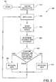
- FIG. 3is a flow chart of a method for force-controlled autodistraction according to an embodiment of the present invention.
- aspects of the present inventionprovide an autodistractor able to dynamically vary a distraction rate of a bone in a limb of a subject, e.g., in response to resistance encountered in the limb during distraction, to achieve a desired limb stiffness.
- a more successful distractionmay be provided.
- a practitioneralso can obtain additional feedback on the state of the lengthening, which may be useful for determining whether there is too much force or too little force, or whether the bone has appropriately healed.
- an autodistractoris provided with a sensor and a controller able to vary a distraction rate, based on a force developed during distraction.
- a sensorIn contrast to fixed displacement-driven distraction, it is believed that embodiments of variable distraction limb lengthening can offer a subject greater convenience and less pain during distraction. Aspects of variable distraction limb lengthening can provide a more optimal lengthening than fixed-displacement modalities.
- Embodiments of the inventioninclude a closed-loop feedback system in the autodistractor for determining a variable limb stiffness (K leg ) from the use of a resistant force measurement (F), a known distractor displacement (x), and a known distractor stiffness (K d ), and for adjusting a gain of the motor in the autodistractor, so that the variable limb stiffness (K leg ) will match a desired limb stiffness.
- the distraction ratei.e., the rate at which the rotation of the motor causes the distractor to lengthen, can be adjusted by varying the gain.
- the distraction ratecan be adjusted based on the difference between the variable limb stiffness and the desired limb stiffness.
- aspects of the inventionare able to use measured force information to ensure that a predetermined value of the resistant force measurement is not exceeded, which can be useful both as a safety mechanism and for implementing a control algorithm using calculated stiffness to dictate an optimal lengthening regime.
- FIG. 1Adepicts an exemplary force-controlled autodistractor 100 for lengthening a bone 110 in accordance with herein-described systems and methods.
- FIG. 1Bis a block diagram showing the cooperation of exemplary components of an exemplary force-controlled autodistractor 100 .
- the bone 110is in a limb (not shown) of a subject (not shown).
- the subjecte.g., a patient
- the subjectmay be a human or animal. While the illustrative bone 110 shown in FIG. 1A represents a human tibia, the bone 110 may be a tibia, fibula, femur, radius, ulna, humerus, or any other bone (e.g., of a limb or digit) deemed by a practitioner to be suitable for lengthening by distraction.
- the autodistractor 100comprises at least one distractor, such as distraction mechanism 120 .
- Distraction mechanism 120is coupled to a first fixator 130 .
- Distraction mechanism 120is also coupled to a second fixator 131 distal to the first fixator 130 .
- Distraction mechanism 120is configured to permit linear motion of the first fixator 130 relative to the second fixator 131 , e.g., substantially parallel to an axis of the distraction mechanism 120 .
- the linear motionmay be, during use, substantially parallel to the length of the bone 110 .
- the first fixator 130is configured to be coupled to a first portion 111 of the bone 110
- the second fixatoris configured to be coupled to a second portion 112 of the bone 110 .
- the first portion 111 and second portion 112 of the bone 110are on opposite sides of an osteotomy 115 of the bone 110 .
- the osteotomy 115may be, for example, a complete osteotomy or a corticotomy.
- the osteotomy 115may be performed at any medically desirable position and angle on the bone 110 , and may be performed on the bone 110 at any medically desirable time prior to commencing distraction of the bone 110 ; i.e., before, during, or after coupling the fixators 130 , 131 to the bone 110 .
- the fixators 130 , 131are coupled to the bone 110 by a plurality of fasteners 135 .
- fasteners 135may be pins, or other means for coupling the fixators 130 , 131 to the bone 110 may be used; for example, a plurality of screws, wires (e.g., Kirschner wires), or any other suitable devices may be used for coupling the fixators 130 , 131 to the bone 110 .
- Any number of fasteners 135 or other suitable coupling devicesmay be used in autodistractor 100 for practicing the invention, as may be medically appropriate for distracting the bone 110 .
- a motor 140is controllable to produce a motion of the first fixator 130 relative to the second fixator 131 such that the first portion 111 of the bone 110 is distracted from the second portion 112 of the bone 110 .
- the relative motionmay be produced by applying force to either of the first fixator 130 or the second fixator 131 , or to both fixators 130 , 131 , so as to increase the distance between the fixators 130 , 131 .
- a force sensor 150is configured to measure a resistant force to the motion.
- the force sensor 150is able to directly measure the resistant force against the motion.
- an exemplary force sensor 150comprises a load cell or strain gauge.
- Another embodimentincludes a force sensor 150 having an appropriate size and dynamic range, placed into a housing of the autodistractor 100 .
- a distractor displacement sensor 155is configured to measure a distractor displacement of the distraction mechanism 120 , e.g., a length (or change in length) of distraction mechanism 120 , or a distance (or change in distance) between the fixators 130 , 131 .
- an exemplary distractor displacement sensor 155comprises a linear variable displacement transducer (LVDT).
- a controller 160is operably coupled (for example, electrically coupled, mechanically coupled, or wirelessly coupled) to the force sensor 150 , the distractor displacement sensor 155 , and the motor 140 .
- the controller 160is configured to adjust a gain of the motor 140 , e.g., by adjusting voltage of an electrical input to the motor 140 .
- Controller 160may, for example, comprise one or more microprocessors.
- an exemplary controller 160may comprise a preliminary breadboard circuit; once the preliminary breadboard circuit has been tested with the force sensor 150 , a suitable integrated circuit for use in controller 160 can readily be designed and manufactured. Operation of an exemplary controller 160 can be controllable using an computer system (not shown), e.g., a personal computer using virtual instrument software such as Labview.
- the controller 160may be configured to provide telemetry, which can be transmitted to the practitioner (e.g., via wired or wireless communication, or via a communication network such as the Internet).
- the use of telemetrymay facilitate assessment of a subject's progress, and may reduce the need for a visit by the subject to a medical or laboratory facility.
- the autodistractor 100may comprise a commercially available autodistractor (for example, an automated distractor device available from Autogenesis, Inc.) reconfigured to practice aspects of the present invention, e.g., by instrumenting the commercially available autodistractor with a force sensor 150 , and by adding or reconfiguring a controller 160 .
- An exemplary position of the force sensor 150can be inside a housing for the distraction mechanism 120 ; in an illustrative example, an automated distractor device available from Autogenesis, Inc. may in some embodiments be instrumented with force sensor 150 positioned next to a main gear of the device.
- aspects of the inventionmay readily be used in connection with autodistractors of numerous other types.
- Further examples of autodistractors that may be suitably adapted for use with aspects of the inventioninclude internal autodistractors that are configured to be placed wholly or partially within the bone 110 , and external autodistractors having external fixators 130 , 131 (e.g., llizarov circular fixators or uniplanar fixators) for attaching the autodistractor 100 to the bone 110 .
- the controller 160may have to be redesigned, e.g., by configuring a circuit board to accept input from the force sensor 150 .
- a further exemplary distraction mechanism 120may comprise guide rods (not shown) for guiding the motion of the first fixator 130 relative to the second fixator 131 .
- a still further exemplary distraction mechanism 120may comprise one or more rods (not shown), such as a telescoping, extensible, or slidable rod, for elongating the distraction mechanism 120 so that separation between the first and second fixators 120 , 121 is increased.
- the exemplary distraction mechanism 120generally includes means for translating a rotary motion of a motor 140 into the linear motion of the first fixator 130 relative to the second fixator 131 ; for example, one or more gears, screws, cables, or the like (not shown) may be used to couple the motor 140 to the first fixator 130 .
- exemplary distraction mechanism 120 and fixators 130 , 131 discussed hereinare merely illustrative of an autodistractor 100 in which the herein described systems and methods may operate and does not limit the implementation of the herein described systems and methods in an autodistractor 100 having differing components and configurations, as the inventive concepts described herein may be implemented using various distraction mechanisms 120 and fixators 130 , 131 having various components and configurations.
- FIG. 2is a diagram illustrating data flow for an exemplary controller 160 for practicing an embodiment of the invention.
- the controller 160is configured to determine a variable limb stiffness 210 using the resistant force 220 , the distractor displacement 230 , and the distractor stiffness 240 .
- the controller 160is configured to adjust a gain 260 of the motor 140 such that the variable limb stiffness 210 will match a desired limb stiffness 250 .
- a closed-loop feedback systemis thereby provided in the autodistractor 100 .
- the controller 160may be also configured to provide telemetry to a practitioner.
- Such telemetrymay, for example, include one or more values selected from a group consisting of the variable limb stiffness 210 , the resistant force 220 , the distractor displacement 230 , the distractor stiffness 240 , the desired limb stiffness 250 , and the gain 260 .
- the resistant force 220is force encountered in the limb that resists (e.g., pushes back against) the distraction of the bone 110 by the autodistractor 100 .
- the autodistraction system of the inventionmay be used to measure the variable limb stiffness 210 in vivo, thereby facilitating studies of the origin of the resistant force 220 . Such measurements may assist in determining the relative contribution of the two tissues. Further aspects of the invention can offer the potential to perform measurements of resistant force 220 during minute oscillatory movements that will allow non-radiographic assessments of bony and soft tissue.
- K legrepresents the variable limb stiffness 210 , i.e., stiffness of the limb.
- Frepresents the resistant force 220 , which can be directly measured by the force sensor 150 .
- xrepresents the distractor displacement 230 , which may be measured by distractor displacement sensor 155 .
- K drepresents the distractor stiffness 240 , which will be known prior to actual use of the autodistractor 100 on a bone 110 , as further discussed below.
- Stiffness(such as variable limb stiffness 210 , distractor stiffness 240 , and desired limb stiffness 250 ) can be expressed in newtons per millimeter (N/mm).
- Resistant force 220can be expressed in newtons
- distractor displacement 230can be expressed in millimeters.
- variable limb stiffness 210 of the legmay be determined, so that it can be compared against the desired limb stiffness 250 .
- An exemplary controller 160is able to convert the difference between variable limb stiffness 210 and desired limb stiffness 250 to a gain 260 .
- An exemplary gain 260is a voltage signal to the motor 140 , which may be increased or decreased by the controller 160 , thereby increasing or decreasing the distraction rate, i.e., the rate of change in the distractor displacement 230 .
- an initial gain 260can be applied to the motor 140 to produce an initial distraction rate, such as a distraction rate of one millimeter per day, which is typically used in a clinical environment.
- the gain 260can then be adjusted by the controller 160 .
- the resistant force 220 encounteredcan be limited to a band. In such embodiments, if the resistant force 220 measured in the autodistractor 100 were to vary outside an upper or lower limit of the band, the gain 260 can be altered appropriately.
- an audible signalcan be sounded if the resistant force 220 varies outside an upper or lower limit of the band.
- An illustrative estimate of the bandcan be based on resistant forces 220 measured by previous ovine experiments, in which the peak resistant force 220 reported is 200 - 300 N in sheep tibia during lengthening.
- the force sensor 220may sense a value of resistant force 220 that a skilled practitioner is able to determine to be high.
- a high value of resistant force 220could indicate that there is premature consolidation, or conversely that there is too much separation resulting in high stresses on the surrounding soft tissue.
- a programmed response of the controller 160may in some embodiments be different; i.e., in the first case, the rate of distraction may be increased to avoid impending consolidation, and in the second, the rate of distraction may be decreased to avoid damage to the soft tissue.
- the practitionercan gauge the forces in the distraction environment, e.g., to head off potential problems, and to guide the distraction based on optimal stiffness profiles for determining desired limb stiffness 250 , such as may be determined by the practitioner.
- the autodistractor 100will have a known distractor stiffness 240 ; for example, stiffness that is attributable to bending of the distraction mechanism 120 and the fasteners 135 as a unit.
- the distractor stiffness 240will be measured without attaching the fixators 130 , 131 to the bone 110 ; for example, a manufacturer of the autodistractor 100 may measure or calculate the value of the distractor stiffness 240 .
- the distractor stiffness 240may be a fixed characteristic of a particular model or design of an embodiment of the autodistractor 100 , or the distractor stiffness 240 may be individually measured or tested for each unit of the autodistractor 100 prior to use of the autodistractor 100 on a subject.
- the distraction mechanism 120 of the autodistractor 100may be mounted on a test-bed (not shown) and prepared for elongation. Mounting may be performed by coupling the fixators 130 , 131 to the test-bed using fasteners 135 that are identical to the fasteners 135 used for coupling the fixators 130 , 131 to bone 100 in surgery, thus allowing a stiffness measurement for the combination of the distractor mechanism 120 and fasteners 135 .
- the test-bedcan comprise a first and second artificial bone segment (not shown) for modeling the first portion 111 and second portion 112 of a bone 110 .
- the artificial bone segmentscan be, for example, aluminum rods.
- the second artificial bone segmentmay be clamped in place and the first artificial bone segment may be allowed to move in response to the elongation.
- a tension spring(not shown) may connect the artificial bone segments to mimic the resistant force 220 in the limb, and a linear variable displacement transducer (LVDT) (not shown) may be fitted between the artificial bone segments.
- the LVDTmay be used to measure the distractor displacement 230 between the artificial bone segments, which may then be used to verify the stiffness of the autodistractor 100 .
- the distractor stiffness 240may be measured a priori by suspending known weights from fasteners 135 (e.g., at the end of the fasteners 135 ) that are coupled to one or more of the artificial bone segments, and measuring the distractor displacement 230 with the LVDT.
- the desired limb stiffness 250is predetermined, e.g., by a skilled practitioner, prior to the use of the autodistractor 100 .
- the desired limb stiffness 250is individually predetermined for a particular subject (not shown) prior to the use of the autodistractor 100 with the subject, e.g., based upon matching a clinical profile of the subject with one or more clinical profiles of prior subjects (e.g., test subjects).
- Empirical determination of a desired limb stiffness 250can be based upon research and statistical techniques generally known to those skilled in the art.
- the desired limb stiffness 250may be determined based on many factors that can be determined empirically, including the quality of the regenerate bone, speed of procedure, pain to the subject, state of the growth plate, and stretch of muscles.
- An empirical determination of optimal values of desired limb stiffness 250may, for example, be performed using the autodistractor 100 in a number of test subjects (e.g., a large number of animals used for testing the autodistractor 100 ). Such test subjects may be divided into groups for undergoing distraction of various rates and rhythms using the autodistractor 100 . Clinical outcomes in terms of growth plate damage, callous formation, and soft tissue effects can be measured and the optimal desired limb stiffness 250 determined by the skilled practitioner. In some embodiments, the practitioner may determine optimal values of the desired limb stiffness 250 that vary according to clinical profiles of the test subjects. Such values of desired limb stiffness 250 may be used to guide lengthening in later use of the autodistractor 110 in a later subject.
- FIG. 3shows the steps of a method 300 for force-controlled autodistraction according to an embodiment of the present invention.
- the method 300begins at start block 301 , and proceeds to block 310 .
- distractor 120is fastened to bone 110 in a limb of the subject.
- a gain 260is applied to motor 140 .
- the initial value of the gain 260may be the gain 260 needed to produce a desired distractor displacement rate (e.g., a change in distractor displacement 230 of about one mm/day).
- the value of the gain 260can be adjusted during use of the method 300 , as discussed below. The method proceeds to block 330 .
- the resistant force 220 in the limbis sensed, using the force sensor 150 .
- the variable limb stiffness 210is determined.
- controller 160can be configured to determine variable limb stiffness 210 using the resistant force 220 , the distractor displacement 230 , and the distractor stiffness 240 .
- a checkis performed by the controller 160 , to compare the variable limb stiffness 210 to the desired limb stiffness 250 . If the variable limb stiffness 210 is lower than the desired limb stiffness 250 , the method 300 proceeds to block 360 , where the gain 260 is increased by the controller 160 , and the method then returns to block 310 . If the variable limb stiffness 210 is higher than the desired limb stiffness 250 , the method 300 proceeds to block 370 , where the gain 260 is decreased by the controller 160 , and the method then returns to block 310 . If the variable limb stiffness 210 is equal to the desired limb stiffness 250 , the method 300 proceeds to block 310 .
Landscapes
- Health & Medical Sciences (AREA)
- Orthopedic Medicine & Surgery (AREA)
- Life Sciences & Earth Sciences (AREA)
- Surgery (AREA)
- Biomedical Technology (AREA)
- Engineering & Computer Science (AREA)
- Nuclear Medicine, Radiotherapy & Molecular Imaging (AREA)
- Heart & Thoracic Surgery (AREA)
- Medical Informatics (AREA)
- Molecular Biology (AREA)
- Animal Behavior & Ethology (AREA)
- General Health & Medical Sciences (AREA)
- Public Health (AREA)
- Veterinary Medicine (AREA)
- Surgical Instruments (AREA)
Abstract
Description
Kleg=(F/x)−Kd
F=(Kleg+Kd)x
Claims (21)
Priority Applications (1)
| Application Number | Priority Date | Filing Date | Title |
|---|---|---|---|
| US11/498,284US8282652B2 (en) | 2006-08-02 | 2006-08-02 | Force-controlled autodistraction |
Applications Claiming Priority (1)
| Application Number | Priority Date | Filing Date | Title |
|---|---|---|---|
| US11/498,284US8282652B2 (en) | 2006-08-02 | 2006-08-02 | Force-controlled autodistraction |
Publications (2)
| Publication Number | Publication Date |
|---|---|
| US20080051779A1 US20080051779A1 (en) | 2008-02-28 |
| US8282652B2true US8282652B2 (en) | 2012-10-09 |
Family
ID=39197628
Family Applications (1)
| Application Number | Title | Priority Date | Filing Date |
|---|---|---|---|
| US11/498,284Expired - Fee RelatedUS8282652B2 (en) | 2006-08-02 | 2006-08-02 | Force-controlled autodistraction |
Country Status (1)
| Country | Link |
|---|---|
| US (1) | US8282652B2 (en) |
Cited By (18)
| Publication number | Priority date | Publication date | Assignee | Title |
|---|---|---|---|---|
| US8834467B2 (en) | 2010-08-11 | 2014-09-16 | Stryker Trauma Sa | External fixator system |
| US8858555B2 (en) | 2009-10-05 | 2014-10-14 | Stryker Trauma Sa | Dynamic external fixator and methods for use |
| US8945128B2 (en) | 2010-08-11 | 2015-02-03 | Stryker Trauma Sa | External fixator system |
| US9101398B2 (en) | 2012-08-23 | 2015-08-11 | Stryker Trauma Sa | Bone transport external fixation frame |
| US9642649B2 (en) | 2010-05-19 | 2017-05-09 | DePuy Synthes Products, Inc. | Orthopedic fixation with imagery analysis |
| US9675382B2 (en) | 2013-03-13 | 2017-06-13 | DePuy Synthes Products, Inc. | External bone fixation device |
| US9788861B2 (en) | 2013-03-13 | 2017-10-17 | DePuy Synthes Products, Inc. | External bone fixation device |
| US9987043B2 (en) | 2014-10-24 | 2018-06-05 | Stryker European Holdings I, Llc | Methods and systems for adjusting an external fixation frame |
| US10010350B2 (en) | 2016-06-14 | 2018-07-03 | Stryker European Holdings I, Llc | Gear mechanisms for fixation frame struts |
| US10349981B2 (en) | 2011-06-23 | 2019-07-16 | Stryker European Holdings I, Llc | Methods and systems for adjusting an external fixation frame |
| US10368913B2 (en) | 2015-08-10 | 2019-08-06 | Stryker European Holdings I, Llc | Adjustment instrument with tactile feedback |
| US10835318B2 (en) | 2016-08-25 | 2020-11-17 | DePuy Synthes Products, Inc. | Orthopedic fixation control and manipulation |
| US10874433B2 (en) | 2017-01-30 | 2020-12-29 | Stryker European Holdings I, Llc | Strut attachments for external fixation frame |
| US11141196B2 (en) | 2010-08-11 | 2021-10-12 | Stryker European Operations Holdings Llc | External fixator system |
| US11304757B2 (en) | 2019-03-28 | 2022-04-19 | Synthes Gmbh | Orthopedic fixation control and visualization |
| US11334997B2 (en) | 2020-04-03 | 2022-05-17 | Synthes Gmbh | Hinge detection for orthopedic fixation |
| US11439436B2 (en) | 2019-03-18 | 2022-09-13 | Synthes Gmbh | Orthopedic fixation strut swapping |
| US12220250B2 (en) | 2016-06-19 | 2025-02-11 | Synthes Gmbh | User interface for strut device |
Families Citing this family (18)
| Publication number | Priority date | Publication date | Assignee | Title |
|---|---|---|---|---|
| US20090192514A1 (en)* | 2007-10-09 | 2009-07-30 | Feinberg Stephen E | Implantable distraction osteogenesis device and methods of using same |
| US9439696B2 (en)* | 2011-06-17 | 2016-09-13 | Biomet Manufacturing, Llc | Implant to stress bone to alter morphology |
| US9204937B2 (en) | 2013-02-19 | 2015-12-08 | Stryker Trauma Gmbh | Software for use with deformity correction |
| US8864763B2 (en) | 2013-03-13 | 2014-10-21 | DePuy Synthes Products, LLC | External bone fixation device |
| EP2997515B1 (en) | 2013-05-14 | 2024-11-27 | Smith & Nephew, Inc. | Apparatus and method for administering a medical device prescription |
| US9333053B2 (en) | 2013-08-07 | 2016-05-10 | Bandar ALYAMI | Orthodontic device |
| US9949758B2 (en) | 2014-03-12 | 2018-04-24 | Orthospin Ltd. | Preloaded medical struts |
| WO2015142298A2 (en)* | 2014-03-19 | 2015-09-24 | Khemiri Mourad | Automatic distractor appliance, electronically assisted devices for distraction or extension (elongation) of bones |
| US11839549B2 (en)* | 2016-04-07 | 2023-12-12 | Kambiz Behzadi | Materials in orthopedics and fracture fixation |
| US10251705B2 (en) | 2016-06-02 | 2019-04-09 | Stryker European Holdings I, Llc | Software for use with deformity correction |
| KR102168431B1 (en)* | 2017-10-24 | 2020-10-21 | 경북대학교 산학협력단 | Active Retractor and Control Method thereof |
| CN120302934A (en)* | 2022-12-23 | 2025-07-11 | 奥叟菲克斯公司 | Tool for adjusting an external fixation post, an adjustable external fixation post, and a kit comprising the fixation post and the tool |
| EP4389030B1 (en)* | 2022-12-23 | 2025-07-23 | Orthofix S.r.l. | Tool for external fixation strut adjustment, adjustable external fixation strut, and kit comprising said fixator strut and said tool |
| EP4389032B1 (en)* | 2022-12-23 | 2025-07-09 | Orthofix S.r.l. | Wrench for external fixation strut adjustment, adjustable external fixation strut, and kit comprising said fixator strut and said wrench |
| EP4491331A3 (en)* | 2022-12-23 | 2025-03-05 | Orthofix S.r.l. | Wrench for external fixation strut adjustment |
| US20240390037A1 (en)* | 2023-05-22 | 2024-11-28 | Nikolaj Wolfson | External fixation device and/or method for a fractured limb |
| IL305408A (en)* | 2023-08-22 | 2025-03-01 | Synthes Gmbh | Accordion maneuver with a bone fixation device |
| CN119548225B (en)* | 2024-11-13 | 2025-09-09 | 武汉大学 | Chip remote control's bone stretch osteogenesis system |
Citations (31)
| Publication number | Priority date | Publication date | Assignee | Title |
|---|---|---|---|---|
| US4501266A (en) | 1983-03-04 | 1985-02-26 | Biomet, Inc. | Knee distraction device |
| US4615338A (en) | 1985-09-18 | 1986-10-07 | Kurgansky Nauchno-Issledovatelsky Institut Experimentalnoi I Klinicheskoi Ortopedii I Travmatologii | Automatic compression-distraction apparatus |
| US4973331A (en) | 1989-03-08 | 1990-11-27 | Autogenesis Corporation | Automatic compression-distraction-torsion method and apparatus |
| US5156605A (en) | 1990-07-06 | 1992-10-20 | Autogenesis Corporation | Automatic internal compression-distraction-method and apparatus |
| US5180380A (en)* | 1989-03-08 | 1993-01-19 | Autogenesis Corporation | Automatic compression-distraction-torsion method and apparatus |
| US5207676A (en)* | 1989-02-27 | 1993-05-04 | Jaquet Orthopedie S.A. | External fixator with controllable damping |
| US5314426A (en)* | 1992-04-16 | 1994-05-24 | Pohl Anthony P | External bone fixation device |
| US5334202A (en)* | 1993-04-06 | 1994-08-02 | Carter Michael A | Portable bone distraction apparatus |
| US5350379A (en) | 1993-02-18 | 1994-09-27 | Genesis Orthopedics | Bone and tissue lengthening device |
| US5415660A (en)* | 1994-01-07 | 1995-05-16 | Regents Of The University Of Minnesota | Implantable limb lengthening nail driven by a shape memory alloy |
| US5429638A (en) | 1993-02-12 | 1995-07-04 | The Cleveland Clinic Foundation | Bone transport and lengthening system |
| US5437668A (en)* | 1994-02-18 | 1995-08-01 | Board Of Trustees Of The University Of Ark. | Apparatus and method for clinical use of load measurement in distraction osteogenesis |
| US5454810A (en)* | 1990-02-05 | 1995-10-03 | Pohl; Anthony P. | External fixation device |
| US5536269A (en) | 1993-02-18 | 1996-07-16 | Genesis Orthopedics | Bone and tissue lengthening device |
| US5601551A (en)* | 1995-03-01 | 1997-02-11 | Smith & Nephew Richards, Inc. | Geared external fixator |
| US5626581A (en) | 1995-11-27 | 1997-05-06 | Volunteers For Medical Engineering | Implantable bone lengthening apparatus |
| US5626579A (en)* | 1993-02-12 | 1997-05-06 | The Cleveland Clinic Foundation | Bone transport and lengthening system |
| US5697165A (en)* | 1994-06-20 | 1997-12-16 | Richardson; James Bruce | System for measuring stiffness of a fractured bone |
| US5704938A (en) | 1996-03-27 | 1998-01-06 | Volunteers For Medical Engineering | Implantable bone lengthening apparatus using a drive gear mechanism |
| US5961553A (en)* | 1995-02-13 | 1999-10-05 | Medinov-Amp | Long bone elongation device |
| US5976125A (en)* | 1995-08-29 | 1999-11-02 | The Cleveland Clinic Foundation | External distractor/fixator for the management of fractures and dislocations of interphalangeal joints |
| US6017341A (en)* | 1997-06-20 | 2000-01-25 | Novo Nordisk A/S | Apparatus for fixation of the bones in a healing bone fracture |
| US6022349A (en)* | 1997-02-12 | 2000-02-08 | Exogen, Inc. | Method and system for therapeutically treating bone fractures and osteoporosis |
| US6033412A (en)* | 1997-04-03 | 2000-03-07 | Losken; H. Wolfgang | Automated implantable bone distractor for incremental bone adjustment |
| US6336929B1 (en) | 1998-01-05 | 2002-01-08 | Orthodyne, Inc. | Intramedullary skeletal distractor and method |
| US20030004518A1 (en)* | 1999-11-15 | 2003-01-02 | Stephan Perren | Method and device for the determination of reduction parameters for the subsequent reduction of a fractured bone |
| US20030144669A1 (en)* | 2001-12-05 | 2003-07-31 | Robinson Randolph C. | Limb lengthener |
| US6673079B1 (en) | 1999-08-16 | 2004-01-06 | Washington University | Device for lengthening and reshaping bone by distraction osteogenesis |
| US20040030395A1 (en)* | 2000-04-13 | 2004-02-12 | Gordon Blunn | Surgical distraction device |
| US6706042B2 (en)* | 2001-03-16 | 2004-03-16 | Finsbury (Development) Limited | Tissue distractor |
| US6761723B2 (en) | 2002-01-14 | 2004-07-13 | Dynamic Spine, Inc. | Apparatus and method for performing spinal surgery |
Family Cites Families (1)
| Publication number | Priority date | Publication date | Assignee | Title |
|---|---|---|---|---|
| JP4090717B2 (en)* | 2001-09-11 | 2008-05-28 | 本田技研工業株式会社 | Motorcycle |
- 2006
- 2006-08-02USUS11/498,284patent/US8282652B2/ennot_activeExpired - Fee Related
Patent Citations (33)
| Publication number | Priority date | Publication date | Assignee | Title |
|---|---|---|---|---|
| US4501266A (en) | 1983-03-04 | 1985-02-26 | Biomet, Inc. | Knee distraction device |
| US4615338A (en) | 1985-09-18 | 1986-10-07 | Kurgansky Nauchno-Issledovatelsky Institut Experimentalnoi I Klinicheskoi Ortopedii I Travmatologii | Automatic compression-distraction apparatus |
| US5207676A (en)* | 1989-02-27 | 1993-05-04 | Jaquet Orthopedie S.A. | External fixator with controllable damping |
| US4973331A (en) | 1989-03-08 | 1990-11-27 | Autogenesis Corporation | Automatic compression-distraction-torsion method and apparatus |
| US5180380A (en)* | 1989-03-08 | 1993-01-19 | Autogenesis Corporation | Automatic compression-distraction-torsion method and apparatus |
| US5454810A (en)* | 1990-02-05 | 1995-10-03 | Pohl; Anthony P. | External fixation device |
| US5156605A (en) | 1990-07-06 | 1992-10-20 | Autogenesis Corporation | Automatic internal compression-distraction-method and apparatus |
| US5314426A (en)* | 1992-04-16 | 1994-05-24 | Pohl Anthony P | External bone fixation device |
| US5429638A (en) | 1993-02-12 | 1995-07-04 | The Cleveland Clinic Foundation | Bone transport and lengthening system |
| US5626579A (en)* | 1993-02-12 | 1997-05-06 | The Cleveland Clinic Foundation | Bone transport and lengthening system |
| US5350379A (en) | 1993-02-18 | 1994-09-27 | Genesis Orthopedics | Bone and tissue lengthening device |
| US5536269A (en) | 1993-02-18 | 1996-07-16 | Genesis Orthopedics | Bone and tissue lengthening device |
| US5334202A (en)* | 1993-04-06 | 1994-08-02 | Carter Michael A | Portable bone distraction apparatus |
| US5415660A (en)* | 1994-01-07 | 1995-05-16 | Regents Of The University Of Minnesota | Implantable limb lengthening nail driven by a shape memory alloy |
| US5437668A (en)* | 1994-02-18 | 1995-08-01 | Board Of Trustees Of The University Of Ark. | Apparatus and method for clinical use of load measurement in distraction osteogenesis |
| US5697165A (en)* | 1994-06-20 | 1997-12-16 | Richardson; James Bruce | System for measuring stiffness of a fractured bone |
| US5961553A (en)* | 1995-02-13 | 1999-10-05 | Medinov-Amp | Long bone elongation device |
| US5601551A (en)* | 1995-03-01 | 1997-02-11 | Smith & Nephew Richards, Inc. | Geared external fixator |
| US5976125A (en)* | 1995-08-29 | 1999-11-02 | The Cleveland Clinic Foundation | External distractor/fixator for the management of fractures and dislocations of interphalangeal joints |
| US5626581A (en) | 1995-11-27 | 1997-05-06 | Volunteers For Medical Engineering | Implantable bone lengthening apparatus |
| US5704938A (en) | 1996-03-27 | 1998-01-06 | Volunteers For Medical Engineering | Implantable bone lengthening apparatus using a drive gear mechanism |
| US6022349A (en)* | 1997-02-12 | 2000-02-08 | Exogen, Inc. | Method and system for therapeutically treating bone fractures and osteoporosis |
| US6033412A (en)* | 1997-04-03 | 2000-03-07 | Losken; H. Wolfgang | Automated implantable bone distractor for incremental bone adjustment |
| US6017341A (en)* | 1997-06-20 | 2000-01-25 | Novo Nordisk A/S | Apparatus for fixation of the bones in a healing bone fracture |
| US6336929B1 (en) | 1998-01-05 | 2002-01-08 | Orthodyne, Inc. | Intramedullary skeletal distractor and method |
| US6673079B1 (en) | 1999-08-16 | 2004-01-06 | Washington University | Device for lengthening and reshaping bone by distraction osteogenesis |
| US20030004518A1 (en)* | 1999-11-15 | 2003-01-02 | Stephan Perren | Method and device for the determination of reduction parameters for the subsequent reduction of a fractured bone |
| US6827721B2 (en)* | 1999-11-15 | 2004-12-07 | Synthes (Usa) | Method and device for the determination of reduction parameters for the subsequent reduction of a fractured bone |
| US20040030395A1 (en)* | 2000-04-13 | 2004-02-12 | Gordon Blunn | Surgical distraction device |
| US6849076B2 (en)* | 2000-04-13 | 2005-02-01 | University College London | Surgical distraction device |
| US6706042B2 (en)* | 2001-03-16 | 2004-03-16 | Finsbury (Development) Limited | Tissue distractor |
| US20030144669A1 (en)* | 2001-12-05 | 2003-07-31 | Robinson Randolph C. | Limb lengthener |
| US6761723B2 (en) | 2002-01-14 | 2004-07-13 | Dynamic Spine, Inc. | Apparatus and method for performing spinal surgery |
Cited By (49)
| Publication number | Priority date | Publication date | Assignee | Title |
|---|---|---|---|---|
| US8858555B2 (en) | 2009-10-05 | 2014-10-14 | Stryker Trauma Sa | Dynamic external fixator and methods for use |
| US8906020B2 (en) | 2009-10-05 | 2014-12-09 | Stryker Trauma Sa | Dynamic external fixator and methods for use |
| US10149701B2 (en) | 2009-10-05 | 2018-12-11 | Stryker European Holdings I, Llc | Dynamic external fixator and methods for use |
| US9351763B2 (en) | 2009-10-05 | 2016-05-31 | Stryker European Holdings I, Llc | Dynamic external fixator and methods for use |
| US9642649B2 (en) | 2010-05-19 | 2017-05-09 | DePuy Synthes Products, Inc. | Orthopedic fixation with imagery analysis |
| US10932857B2 (en) | 2010-05-19 | 2021-03-02 | DePuy Synthes Products, Inc. | Orthopedic fixation with imagery analysis |
| US11896313B2 (en) | 2010-05-19 | 2024-02-13 | DePuy Synthes Products, Inc. | Orthopedic fixation with imagery analysis |
| US10376285B2 (en) | 2010-08-11 | 2019-08-13 | Stryker European Holdings I, Llc | External fixator system |
| US10285734B2 (en) | 2010-08-11 | 2019-05-14 | Stryker European Holdings I, Llc | External fixator system |
| US9717527B2 (en) | 2010-08-11 | 2017-08-01 | Stryker European Holdings I, Llc | External fixator system |
| US9730730B2 (en) | 2010-08-11 | 2017-08-15 | Stryker European Holdings I, Llc | External fixator system |
| US11141196B2 (en) | 2010-08-11 | 2021-10-12 | Stryker European Operations Holdings Llc | External fixator system |
| US8945128B2 (en) | 2010-08-11 | 2015-02-03 | Stryker Trauma Sa | External fixator system |
| US9839445B2 (en) | 2010-08-11 | 2017-12-12 | Stryker European Holdings I, Llc | External fixator system |
| US8834467B2 (en) | 2010-08-11 | 2014-09-16 | Stryker Trauma Sa | External fixator system |
| US12035944B2 (en) | 2010-08-11 | 2024-07-16 | Stryker European Operations Holdings Llc | External fixator system |
| US10080585B2 (en) | 2010-08-11 | 2018-09-25 | Stryker European Holdings I, Llc | External fixator system |
| US9220533B2 (en) | 2010-08-11 | 2015-12-29 | Stryker Trauma Sa | External fixator system |
| US10349981B2 (en) | 2011-06-23 | 2019-07-16 | Stryker European Holdings I, Llc | Methods and systems for adjusting an external fixation frame |
| US12150677B2 (en) | 2011-06-23 | 2024-11-26 | Stryker European Operations Holdings Llc | Methods and systems for adjusting an external fixation frame |
| US11419635B2 (en) | 2011-06-23 | 2022-08-23 | Stryker European Operations Holdings Llc | Methods and systems for adjusting an external fixation frame |
| US9101398B2 (en) | 2012-08-23 | 2015-08-11 | Stryker Trauma Sa | Bone transport external fixation frame |
| US11090086B2 (en) | 2012-08-23 | 2021-08-17 | Stryker European Operations Holdings Llc | Bone transport external fixation frame |
| US10405888B2 (en) | 2012-08-23 | 2019-09-10 | Stryker European Holdings I, Llc | Bone transport external fixation frame |
| US11744616B2 (en) | 2012-08-23 | 2023-09-05 | Stryker European Operations Holdings Llc | Bone transport external fixation frame |
| US9820775B2 (en) | 2012-08-23 | 2017-11-21 | Styker European Holdings I, LLC | Bone transport external fixation frame |
| US9675382B2 (en) | 2013-03-13 | 2017-06-13 | DePuy Synthes Products, Inc. | External bone fixation device |
| US10470800B2 (en) | 2013-03-13 | 2019-11-12 | DePuy Synthes Products, Inc. | External bone fixation device |
| US9788861B2 (en) | 2013-03-13 | 2017-10-17 | DePuy Synthes Products, Inc. | External bone fixation device |
| US10492832B2 (en) | 2014-10-24 | 2019-12-03 | Stryker European Holdings I, Llc | Methods and systems for adjusting an external fixation frame |
| US11207103B2 (en) | 2014-10-24 | 2021-12-28 | Stryker European Operations Holdings Llc | Methods and systems for adjusting an external fixation frame |
| US9987043B2 (en) | 2014-10-24 | 2018-06-05 | Stryker European Holdings I, Llc | Methods and systems for adjusting an external fixation frame |
| US10368913B2 (en) | 2015-08-10 | 2019-08-06 | Stryker European Holdings I, Llc | Adjustment instrument with tactile feedback |
| US11083497B2 (en) | 2015-08-10 | 2021-08-10 | Stryker European Operations Holdings Llc | Adjustment instrument with tactile feedback |
| US12201325B2 (en) | 2016-06-14 | 2025-01-21 | Stryker European Operations Holdings Llc | Gear mechanisms for fixation frame struts |
| US11504160B2 (en) | 2016-06-14 | 2022-11-22 | Stryker European Operations Holdings Llc | Gear mechanisms for fixation frame struts |
| US10010350B2 (en) | 2016-06-14 | 2018-07-03 | Stryker European Holdings I, Llc | Gear mechanisms for fixation frame struts |
| US11974781B2 (en) | 2016-06-14 | 2024-05-07 | Stryker European Operations Holdings Llc | Gear mechanisms for fixation frame struts |
| US12220250B2 (en) | 2016-06-19 | 2025-02-11 | Synthes Gmbh | User interface for strut device |
| US10835318B2 (en) | 2016-08-25 | 2020-11-17 | DePuy Synthes Products, Inc. | Orthopedic fixation control and manipulation |
| US11918292B2 (en) | 2016-08-25 | 2024-03-05 | DePuy Synthes Products, Inc. | Orthopedic fixation control and manipulation |
| US10874433B2 (en) | 2017-01-30 | 2020-12-29 | Stryker European Holdings I, Llc | Strut attachments for external fixation frame |
| US11723690B2 (en) | 2017-01-30 | 2023-08-15 | Stryker European Operations Holdings Llc | Strut attachments for external fixation frame |
| US12369948B2 (en) | 2017-01-30 | 2025-07-29 | Stryker European Operations Holdings Llc | Strut attachments for external fixation frame |
| US11648035B2 (en) | 2019-03-18 | 2023-05-16 | Synthes Gmbh | Orthopedic fixation strut swapping |
| US11439436B2 (en) | 2019-03-18 | 2022-09-13 | Synthes Gmbh | Orthopedic fixation strut swapping |
| US11304757B2 (en) | 2019-03-28 | 2022-04-19 | Synthes Gmbh | Orthopedic fixation control and visualization |
| US11893737B2 (en) | 2020-04-03 | 2024-02-06 | Synthes Gmbh | Hinge detection for orthopedic fixation |
| US11334997B2 (en) | 2020-04-03 | 2022-05-17 | Synthes Gmbh | Hinge detection for orthopedic fixation |
Also Published As
| Publication number | Publication date |
|---|---|
| US20080051779A1 (en) | 2008-02-28 |
Similar Documents
| Publication | Publication Date | Title |
|---|---|---|
| US8282652B2 (en) | Force-controlled autodistraction | |
| US5873843A (en) | Assessing the state of union in a bone fracture | |
| US20130041288A1 (en) | Apparatus and Method of Monitoring Healing and/or Assessing Mechanical Stiffness of a Bone Fracture Site or the Like | |
| Brink et al. | Tension band wiring of the olecranon: is it really a dynamic principle of osteosynthesis? | |
| US20020010465A1 (en) | Frame fixator and operation system thereof | |
| EP2464297B1 (en) | Orthopedic external fixator | |
| US9066757B2 (en) | Orthopedic external fixator and method of use | |
| WO2011146739A1 (en) | Methods and devices to decrease tissue trauma during surgery | |
| EP0740927B1 (en) | Bone fixator | |
| US20230389962A1 (en) | Implantable distraction device | |
| CN108324358B (en) | Fracture fixation device and fracture reduction system | |
| EP0450423B1 (en) | Apparatus for the retention of body parts with injured ligaments and/or bones | |
| KR100399004B1 (en) | Frame fixator and operation system thereof | |
| Gardner et al. | Temporal variation of applied inter fragmentary displacement at a bone fracture in harmony with maturation of the fracture callus | |
| RU2833763C1 (en) | System for controlling process of distraction osteosynthesis based on feedback with distraction forces in automated transosseous compression-distraction apparatus | |
| Morasiewicz et al. | The impact of the type of derotation mechanism on the stiffness of the Ilizarov fixator | |
| WO2025165259A1 (en) | System for controlling the process of distraction osteosynthesis | |
| RU2096023C1 (en) | Method for controlling and adjusting reliability of fixation of bone fragments | |
| RU137717U1 (en) | AUTOMATED COMPRESSION-DISTRACTION MACHINE | |
| CN120131026A (en) | Smart wearable limb activity monitoring device for pediatric surgery postoperative rehabilitation | |
| RU55272U1 (en) | DEVICE FOR REPOSITION OF BONE FRAGMENTS | |
| RU2185121C2 (en) | Device for osseous osteosynthesis | |
| RU2354325C1 (en) | Rod apparatus for transosteal tibia osteosynthesis | |
| Harris et al. | Control of movement and fracture stiffness monitoring with external fixation | |
| Zhang et al. | Validation of Feedback Control Approach for an Implantable Limb Lengthening Device |
Legal Events
| Date | Code | Title | Description |
|---|---|---|---|
| AS | Assignment | Owner name:NEMOURS FOUNDATION, THE, FLORIDA Free format text:ASSIGNMENT OF ASSIGNORS INTEREST;ASSIGNORS:MACKENZIE, WILLIAM;RAHMAN, TARIQ;AKINS, ROBERT;REEL/FRAME:018794/0517;SIGNING DATES FROM 20060829 TO 20070118 Owner name:NEMOURS FOUNDATION, THE, FLORIDA Free format text:ASSIGNMENT OF ASSIGNORS INTEREST;ASSIGNOR:YOUNGER, ALASTAIR;REEL/FRAME:018794/0604 Effective date:20061212 Owner name:NEMOURS FOUNDATION, THE, FLORIDA Free format text:ASSIGNMENT OF ASSIGNORS INTEREST;ASSIGNORS:MACKENZIE, WILLIAM;RAHMAN, TARIQ;AKINS, ROBERT;SIGNING DATES FROM 20060829 TO 20070118;REEL/FRAME:018794/0517 | |
| STCF | Information on status: patent grant | Free format text:PATENTED CASE | |
| CC | Certificate of correction | ||
| FPAY | Fee payment | Year of fee payment:4 | |
| MAFP | Maintenance fee payment | Free format text:PAYMENT OF MAINTENANCE FEE, 8TH YR, SMALL ENTITY (ORIGINAL EVENT CODE: M2552); ENTITY STATUS OF PATENT OWNER: SMALL ENTITY Year of fee payment:8 | |
| FEPP | Fee payment procedure | Free format text:MAINTENANCE FEE REMINDER MAILED (ORIGINAL EVENT CODE: REM.); ENTITY STATUS OF PATENT OWNER: SMALL ENTITY | |
| LAPS | Lapse for failure to pay maintenance fees | Free format text:PATENT EXPIRED FOR FAILURE TO PAY MAINTENANCE FEES (ORIGINAL EVENT CODE: EXP.); ENTITY STATUS OF PATENT OWNER: SMALL ENTITY | |
| STCH | Information on status: patent discontinuation | Free format text:PATENT EXPIRED DUE TO NONPAYMENT OF MAINTENANCE FEES UNDER 37 CFR 1.362 | |
| FP | Lapsed due to failure to pay maintenance fee | Effective date:20241009 |