US8281703B2 - Mitigating recoil in a ballistic robot - Google Patents
Mitigating recoil in a ballistic robotDownload PDFInfo
- Publication number
- US8281703B2 US8281703B2US13/335,704US201113335704AUS8281703B2US 8281703 B2US8281703 B2US 8281703B2US 201113335704 AUS201113335704 AUS 201113335704AUS 8281703 B2US8281703 B2US 8281703B2
- Authority
- US
- United States
- Prior art keywords
- disrupter
- barrel
- mount
- carriage
- rails
- Prior art date
- Legal status (The legal status is an assumption and is not a legal conclusion. Google has not performed a legal analysis and makes no representation as to the accuracy of the status listed.)
- Active
Links
Images


Classifications
- F—MECHANICAL ENGINEERING; LIGHTING; HEATING; WEAPONS; BLASTING
- F41—WEAPONS
- F41A—FUNCTIONAL FEATURES OR DETAILS COMMON TO BOTH SMALLARMS AND ORDNANCE, e.g. CANNONS; MOUNTINGS FOR SMALLARMS OR ORDNANCE
- F41A25/00—Gun mountings permitting recoil or return to battery, e.g. gun cradles; Barrel buffers or brakes
- F41A25/02—Fluid-operated systems
- F41A25/04—Fluid-operated systems adjustable, e.g. in relation to the elevation of the gun
- F—MECHANICAL ENGINEERING; LIGHTING; HEATING; WEAPONS; BLASTING
- F41—WEAPONS
- F41B—WEAPONS FOR PROJECTING MISSILES WITHOUT USE OF EXPLOSIVE OR COMBUSTIBLE PROPELLANT CHARGE; WEAPONS NOT OTHERWISE PROVIDED FOR
- F41B9/00—Liquid ejecting guns, e.g. water pistols, devices ejecting electrically charged liquid jets, devices ejecting liquid jets by explosive pressure
- F41B9/0003—Liquid ejecting guns, e.g. water pistols, devices ejecting electrically charged liquid jets, devices ejecting liquid jets by explosive pressure characterised by the pressurisation of the liquid
- F41B9/0031—Liquid ejecting guns, e.g. water pistols, devices ejecting electrically charged liquid jets, devices ejecting liquid jets by explosive pressure characterised by the pressurisation of the liquid the liquid being pressurised at the moment of ejection
- F41B9/0043—Pressurisation by explosive pressure
- F41B9/0046—Disruptors, i.e. for neutralising explosive devices
- F—MECHANICAL ENGINEERING; LIGHTING; HEATING; WEAPONS; BLASTING
- F41—WEAPONS
- F41H—ARMOUR; ARMOURED TURRETS; ARMOURED OR ARMED VEHICLES; MEANS OF ATTACK OR DEFENCE, e.g. CAMOUFLAGE, IN GENERAL
- F41H11/00—Defence installations; Defence devices
- F41H11/12—Means for clearing land minefields; Systems specially adapted for detection of landmines
- F41H11/16—Self-propelled mine-clearing vehicles; Mine-clearing devices attachable to vehicles
- F—MECHANICAL ENGINEERING; LIGHTING; HEATING; WEAPONS; BLASTING
- F41—WEAPONS
- F41H—ARMOUR; ARMOURED TURRETS; ARMOURED OR ARMED VEHICLES; MEANS OF ATTACK OR DEFENCE, e.g. CAMOUFLAGE, IN GENERAL
- F41H7/00—Armoured or armed vehicles
- F41H7/005—Unmanned ground vehicles, i.e. robotic, remote controlled or autonomous, mobile platforms carrying equipment for performing a military or police role, e.g. weapon systems or reconnaissance sensors
Definitions
- This inventionrelates to ballistic or projectile firing systems, and more particularly to devices and methods for mitigating recoil during operation of such systems.
- Ballistic weapons or other projectile firing systemstypically generate recoil forces proportionate to the discharge forces or the mass and acceleration of the projectile.
- the resulting recoil impulse or “kick”corresponds to the recoil force integrated over time.
- a recoil mitigation deviceserves to attenuate or dampen the force-time profile during discharge, for example, to create a longer, lower amplitude recoil impulse.
- Powered weapon firing systemsmay be integrated into a firing system and may include hydraulics, pneumatics and friction brakes. Such systems are often complex, expensive, and applicable to a single firing system into which it is integrated. Many such systems position the mitigation device entirely to one side of the firing system and may thus cause binding of the mitigation device or firing system or pitching of the firing device due to the presence of resistance to recoil only from one side.
- Recoilaffects the targeting accuracy of the firing system and excessive recoil may injure an operator or damage the system or system support structure.
- Certain ballistic applicationssuch as rocket launchers and Percussion Actuated Non-electric (“PAN”) disrupters require both high discharge forces and a high degree of accuracy. These factors are particularly significant in the context of smaller (e.g., 80 lbs or less) EOD robotic platforms, such as the iRobot PackBot EODs, which are designed to be relatively lightweight.
- Disruptersare explosive ordnance disposal (EOD) tools designed to remotely disable and render-safe improvised explosive devices (IEDs) without initiating the IEDs.
- EODexplosive ordnance disposal
- the disruptercan include a breech for loading the shell, a barrel, and a blasting cap, detonating cord, electrical shock tube initiator or other initiating device.
- a water loadmay be used to open explosive packages and disrupt the explosives and firing train.
- disruptershave become commonplace in Explosive Ordnance Disposal (EOD) communities, including the PAN Disrupter noted above (one version manufactured by Ideal Products of Lexington, Ky. under license from Sandia National Laboratory) and the RE 12-12 disrupter. These disrupters are often used on a static mount or more recently on dynamic platforms such as on robot arms. In ordinary use, they are mounted on very stable, very robust mechanical platforms, which are not expected to move or otherwise articulate. Robotic arms can be articulated, electrically powered, not typically back-driveable, often light duty, and often not suited for use with standard disruptors.
- EODExplosive Ordnance Disposal
- a disrupteris mounted on a robotic arm of an EOD robot and a recoil mitigation device (“RMD”) or “recoilless mount” serves to mitigate recoil transferred from the barrel or body of the disrupter to the robotic arm or robot.
- RMDrecoil mitigation device
- One recoilless mount embodimentincludes a pair of gas spring assemblies having gas cylinders and piston rods slideably received within the gas cylinders. The gas cylinders are attached to a robot mount block and the piston rods are attached by a barrel mount to the disrupter barrel forward of the robot mount. The gas spring assemblies are aligned parallel to and adjacent the disrupter barrel and the robot mount block defines an aperture, passage or other formation to provide clearance for axial movement of the barrel relative to the mount during discharge of the disrupter.
- the robot mount blockcan also serve as a bearing surface relative to the disrupter barrel to support and guide the disrupter as it travels relative to the robot mount block during the recoil mitigation cycle.
- the recoil forcesare dampened through compression of the gases in the gas spring as the barrel recoils towards the robot mount block.
- the gas springscan be attached to the robot mount block at multiple points or can attach to multiple robot mounts to stabilize against pitching or rocking of the disrupter during discharge.
- a front barrel mountsupports the forward ends of a pair of rails aligned substantially parallel to and adjacent the disrupter barrel while a rear barrel mount supports the rearward ends of the pair of rails.
- the recoilless mountattaches to the robot via a slidable rail carriage. Springs disposed along the rails bias the slidable rail carriage in a rearward position. The rails move through the carriage in response to the recoil forces of the disrupter barrel and opposed dampening forces of the springs. Compliant stops can be used at either end of the rails to limit movement of the carriage along the rails.
- the rail carriageis formed to attach to the rails on opposite sides of the barrel and includes an aperture, recess or other formation to provide clearance for axial movement of the barrel during discharge of the disrupter.
- the recoilless mountcan be readily adapted for use with various ordnances by fitting the recoilless mount with the appropriate barrel mounts for the selected ordnance. Additionally, the recoilless mount can be adjustable, for example by varying the spring or rail length, spring stiffness or adjusting other parameters for a given application.
- the deviceincludes first and second gas spring assemblies mountable in substantially parallel alignment with a barrel of a disrupter with the first and second gas spring assemblies spaced to accommodate the barrel of the disrupter between the first and second gas spring assemblies.
- the first and second gas spring assembliesinclude a gas cylinder and a piston rod slideably received within the gas cylinder with a distal end of the piston rod extending outwardly from the gas cylinder.
- a disrupter mountis connected to one of the gas cylinder and the distal end of the piston rod and a robot mount block is connected to the other of the gas cylinder and the distal end of the piston rod.
- the robot mount blockis configured to be mounted to a robotic support platform.
- the mount blockat least partially encloses the barrel of a disrupter when the disrupter is mounted between the spring elements and permits axial disrupter movement during discharge of the disrupter.
- the robot mount blockis connectable to a robotic arm.
- the disrupter mountis connectable to a forward section of a barrel of a disrupter.
- the disrupter mountcomprises a barrel clamp configured to apply clamping forces to a disrupter barrel.
- the barrel clampincludes a barrel clamp base and a barrel clamp cap together defining complimentary clamping surfaces.
- the robot mount blockincludes opposing sides each defining a clamping surface for clamping the gas cylinder of one of the first and second gas spring assemblies, and further includes first and second robot mount block clamps attachable to the robot mount block to secure the first and second gas spring assemblies to the robot mount block.
- the deviceincludes a supplemental support spaced apart from the robot mount block for supporting the first and second gas spring assemblies and to reduce pitching during discharge of the disrupter.
- the deviceincludes a rail assembly having first and second rails in substantially parallel alignment and each having a forward end and a rearward end.
- a rail slider carriagedefines first and second rail apertures to receive the first and second rails respectively so as to be slidably moveable relative the first and second rails.
- the rail slider carriageis configured to at least partially enclose a disrupter between the first and second rails and is further configured to allow axial movement of the carriage along the disrupter barrel during recoil of the disrupter.
- First and second springsare disposed respectively along the first and second rails and configured to bias the carriage towards one of the first and second ends of the first and second rails and to compress to dampen recoil forces during discharge of a disrupter.
- a disrupter mountis connected to one of the rail assembly and the rail slider carriage.
- a robot mountis connected to the other of the rail assembly and the rail slider carriage.
- the disrupter mountis connectable to a PAN disrupter.
- the robot mountis connectable to a robotic arm.
- the disrupter mountcomprises a barrel clamp configured to apply clamping forces to a disrupter barrel.
- the barrel clampcomprises a barrel clamp base and a barrel clamp cap, together defining a cylindrical barrel clamping surface.
- the devicein another embodiment, includes a compliant stop connected to one of the rail assembly and the carriage to limit movement of the carriage along the rail assembly.
- the disrupter mountincludes first and second barrel clamps attachable to the rail assembly at the first and second ends of the first and second rails.
- a gas springis attached to the carriage in parallel with the rail assembly to further dampen bi-directional movement of the carriage along the rail assembly.
- the disrupter recoil mitigation deviceincludes first and second gas spring assemblies mountable in substantially parallel alignment with a barrel of a disrupter.
- the first and second gas spring assembliesare spaced to accommodate the barrel of the disrupter between the first and second gas spring assemblies.
- the first and second gas spring assemblieseach comprise a gas cylinder and a piston rod slideably received within the gas cylinder with a distal end extending outwardly from the gas cylinder.
- a disrupter mountis connected to one of the gas cylinder and the distal end of the piston rod and a robot mount block is connected to the other of the gas cylinder and the distal end of the piston rod.
- the robot mount blockis configured for mounting to a robotic support platform.
- the robot mount blockis configured to at least partially enclose the barrel of a disrupter when the disrupter is mounted between the spring elements and to permit axial disrupter movement during discharge of the disrupter.
- Another aspect of the inventionfeatures a method of mitigating recoil exerted on a robotic support platform during firing of a disrupter.
- the methodincludes mounting first portions of a pair of spring elements to the barrel of the disrupter, the spring elements being substantially parallel to the barrel; and the mounting second portions of the spring elements to the robotic support platform.
- the methodincludes biasing the barrel in a forward position relative to the robotic support platform and compressing the spring elements as the disrupter is discharged to mitigate recoil transfer to the robotic support platform.
- the spring elementsare one of gas springs and coil springs.
- mounting the second portions of the spring elementsincludes positioning the barrel of the disrupter in a passage in a robot mounting block such that the barrel of the disrupter moves rearward through the passage during compression of the spring elements.
- mounting second portions of the spring elementsincludes supporting the spring elements at multiple axially spaced locations to resist pitching of the spring elements during discharge of the disrupter.
- FIG. 1is a perspective view of an EOD robot fitted with a disrupter according to one embodiment.
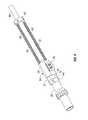
- FIG. 2is a perspective view of a disrupter.
- FIG. 3is a perspective view of a disrupter and recoilless mount combination according to one embodiment.
- FIG. 4is a perspective view of the recoilless mount of FIG. 3 .
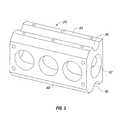
- FIG. 5is a perspective view of a robot mount block.
- FIG. 6is a perspective view of a robot mount block clamp.
- FIG. 7is a perspective view of a barrel mounting plate for use with supplemental mounts.
- FIG. 8is a perspective view of a disrupter and recoilless mount combination according to another embodiment.
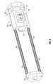
- FIG. 9is a perspective view of the recoilless mount of FIG. 8 .
- FIG. 10is a perspective view of a rail slider carriage.
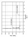
- FIG. 11is a graphical representation of recoil impulse curves for non-mitigated and mitigated disrupter discharges.
- a recoil mitigation device(“recoilless mount”) provides dampening of recoil generated during discharge of a projectile from a projectile firing device such as a disrupter.
- recoil dampingis provided by a pair of gas shocks or gas springs interposed between the disrupter and the disrupter support platform.
- recoil dampingis provided by a pair of rails carrying coil springs and a rail carriage, the rails being connected to the disrupter barrel and the rail carriage being connected to the disrupter support platform.
- Preferred embodimentsmay be used to mitigate recoil experienced by any support platform carrying a projectile firing device. That being said, the embodiments described herein are shown in the context of a disrupter mounted on a robotic arm.
- disrupteras used herein, generally includes any launcher, projectile firing device or ordnance.
- robotand “robot arm” generally includes any non-human ordnance support platform.
- Recoil from discharge of a water loaded disruptertypically ranges between 5-10 pounds-force-seconds while recoil from discharge of a metal slug load typically ranges between 4-7 pounds-force-seconds.
- disrupter recoil experienced by a robotic armis of a higher magnitude than the typical 3 pounds-force-seconds generated by most human-borne weapons.
- the PAN disrupteris positionable using a robotic arm with a series of arm lengths and articulated joints. Recoil during discharge of the disrupter causes the EOD robot to pitch or rock backwards during firing, reducing the accuracy or efficacy of the ordnance. Additionally, the robotic arms, joints or other robot platform elements can be damaged by unmitigated, repeated or excessive recoil.
- FIG. 1is a perspective view of an EOD (explosive ordnance disposal) robot 2 fitted with a disrupter 4 according to one embodiment.
- the depicted robot 2provides a remote mobile platform for positioning and operating disrupter 4 .
- a robotic arm 6extends from robot 2 and includes articulated joints 8 , which provide multiple degrees of freedom for precise positioning of disrupter 4 .
- Joints 8may include controlled drive motors coordinated to accurately position the distal end of robotic arm 6 carrying disrupter 4 .
- FIG. 2is a perspective view of a disrupter 4 having a breech 10 for loading a projectile to be discharged, a barrel 12 defining a central bore for passage of the projectile upon firing, and an initiator 14 for initiating firing or discharge of the projectile from an elongated barrel 12 .
- An example of an explosives disruptor having such a designis the PAN (Percussion Actuated Non-electric) disrupter, designed by Sandia National Laboratories and available under the trademark PAN DISRUPTERTM.
- PANPercussion Actuated Non-electric
- FIG. 3is a perspective view of a disrupter and recoilless mount combination according to one embodiment.
- FIG. 4is a bottom view of the recoilless mount of FIG. 3 , without a disrupter attached.
- barrel 12 of disrupter 4supports recoilless mount 20 with a forward barrel mount 22 and a robot mount block 24 .
- Recoilless mount 20includes first and second gas springs 28 and 30 comprising gas cylinders 32 and piston rods 34 slideably received within gas cylinders 32 . The free or distal ends of piston rods 34 are attached to forward barrel mount 22 .
- Gas cylinders 32are secured to mount block 24 by mount block clamps 36 .
- Gas cylinders 32are further stabilized by a rearward mount 26 spaced apart from mount block 24 and attached thereto by a connector plate 38 .
- mount block 24may be lengthened and gas cylinders 32 positioned and attached to provide suitable stability without the need for rearward mount 26 .
- Mount block 24is depicted here with connector plate 38 and a dove-tail bracket 40 for attachment to a complimentary dove-tailed recess bracket carried on robotic arm 6 .
- Dove tail bracket 40provides for rapid attachment and removal of disruptor 4 from robotic arm 6 . This is particularly advantageous with single shot disrupters in a scenario requiring disruption of multiple explosive devices.
- Gas springs 28can be selected to provide a desired resistance or displacement of piston rod 34 within gas cylinder 32 .
- higher pressure, higher volume or longer gas spring 28can be advantageous in applications requiring higher load ordnances.
- gas springs 28can be replaced with coil springs or other mechanical, electrical or magnetic biasing or resistance devices.
- Forward barrel mount 22comprises two complimentary portions of a cylindrical surface, i.e., a clamp base and a clamp cap, and is attachable to barrel 12 by clamping the base and cap.
- barrel mount 22is an integral slotted annulus slidable over the forward end of barrel 12 and attachable thereto by closure of a slot, e.g., through tightening of a fastener, to generate suitable clamping forces.
- any other means of attaching forward barrel mount 22 to barrel 12can be used.
- Barrel mount 22can be affixed to any suitable part of a launcher or ordnance.
- Rearward mount 26serves to affix the rearward ends of gas springs 28 and 30 together substantially parallel to barrel 12 .
- rearward mount 26need not be clamped to barrel 12 , but can define a passage to allow movement of barrel 12 through rearward mount 26 as recoil of barrel 12 drives piston rods 34 slidably into gas cylinders 32 .
- gas springs 28 and 30can be end-turned and the respective attachment points to forward mount 22 and robot mount block 24 interchanged and still provide suitable sliding operation of gas cylinders 28 and 30 . Accordingly, reversal or exchange of any number of sliding elements, mounts, or other elements described herein may be accomplished within the scope of the present invention.
- the various structural mounts, bracketry, or other structural elements described hereinmay be constructed from a wide variety of materials including, but not necessarily limited to, aluminum, steel, high strength plastics or other suitable metal or non-metal materials.
- FIG. 5is a perspective view of a robot mount block 24 .
- mount block 24includes opposing lateral sides 44 defining recessed clamping surfaces 46 for receiving a portion of gas springs 28 and 30 .
- Mount block clamps 36attach to mount block 24 along sides 44 to secure gas springs 28 and 30 .
- Mount block 24further defines a central barrel passage 40 sized to allow axially rearward movement of barrel 12 as recoil of barrel 12 drives piston rods 34 slidably into gas cylinders 32 . Additional recesses or passages may be formed in mount block 24 as necessary for receipt of fasteners inserted through mount block clamps 36 or plate 38 or to reduce the weight of mount block 24 .
- Mount block 24is configured to align gas springs 28 and 30 parallel to barrel 12 on either side of barrel 12 . Use of paired parallel gas springs 28 and 30 avoids binding associated with use of a single spring and avoids pitching of barrel 12 away from either spring. As with mount block 24 , mount block clamps 36 or any other RMA elements may include any number of openings, recesses, chamfers and the like to reduce the weight of RMA 20 for use on robot 2 .
- FIG. 6is a perspective view of a robot mount block clamp 36 defining clamp-side clamping surfaces 48 complimentary to block-side clamping surfaces 44 for securing gas springs 28 and 30 .
- clamp 36can include any number of passages or other features to accommodate fastening of clamps 36 to mount block 24 .
- FIG. 7is a perspective view of a rearward mount plate 26 depicting barrel passage 40 and openings for attachment of gas springs 28 and 30 and support plate 38 .
- FIG. 8is a perspective view of another disrupter and recoilless mount combination 50 .
- FIG. 9is a perspective view of the recoilless mount of FIG. 8 without an attached disrupter.
- a recoilless mount 54carries a disrupter 52 at multiple points along the barrel 56 of disrupter 52 .
- Recoilless mount 54comprises first and second rails 58 and 60 attached at the forward end to barrel 56 by a forward barrel mount 62 .
- First and second rails 58 and 60are further attached to barrel 56 at their rearward ends by a rearward barrel mount 64 .
- First and second rails 58 and 60are aligned substantially parallel to and on opposite sides of barrel 56 .
- First and second rails 58 and 60carry a rail slider carriage 66 .
- Carriage 66is biased towards a first rearward position 68 by springs 70 against compliant stops 72 .
- Carriage 66can mount directly to robot arm 6 or can include a dove tail mount 76 for ease of attachment and removal as described earlier.
- Rails 58 and 60comprise elongated rods carrying threads or other suitable attachment mechanism for attachment to forward barrel mount 62 and rearward barrel mount 64 .
- Rails 58 - 60can comprise any metal or non-metal material having sufficient strength, stiffness and durability to perform as guides for carriage 66 under recoil loading upon firing of disrupter 52 .
- Recoil of disrupter 52 upon firingcauses forward barrel mount 62 to compress springs 70 towards carriage 66 as rails 58 and 60 are driven rearward through carriage 66 .
- Springs 70can be selected to provide suitable resistance to forward movement of carriage 66 along rails 58 and 60 depending on the application. Similarly, multiple springs can be stacked in series or nested to provide varying degrees of resistance.
- Compliant stops 72comprise rubber or other resilient or compliant material to suitably stop carriage 66 as it is returned to rearward position 68 springs 70 .
- rails 58 and 60 and springs 70are selected to provide sufficient travel and dampening such that carriage 66 does not fully compress springs 70 during recoil, to avoid additional shocks or impulses to robotic arm 6 .
- Forward barrel mount 62 or rearward barrel mount 64may comprise multiple clamping components, i.e., a clamp base and clamp cap, or may comprises unitary clamps having a closable slot other clamping feature. Accordingly, mounts 62 and 64 may be slid over barrel 56 during assembly or may be assembled around barrel 56 .
- FIG. 10is a perspective view of a rail slider carriage 66 defining rail passages 78 for sliding receipt of rails 58 and 60 and further defining barrel clearance passage 74 .
- Carriage 66slidably connects to rails 58 and 60 on either side of barrel 56 and defines a clearance passage 74 sized to allow longitudinal free movement of carriage 66 along barrel 56 .
- Carriage 66may extend between rails 58 and 60 on one or both sides of barrel 56 . Accordingly, clearance passage 74 may comprises a recess or a bore carriage 66 .
- Carriage 66may be constructed of aluminum, steel or other structurally suitable material.
- FIG. 11is a graphical representation of recoil impulse curves for non-mitigated and mitigated disrupter discharges.
- a method of mitigating recoil exerted on a robotic support platform during firing of a disrupterincludes aligning a pair of spring elements in parallel with the barrel of the disrupter. The method further includes mounting a forward end of the spring elements to the barrel of the disrupter and mounting the rearward end of the spring elements to a robot mounting block attachable to the robotic support platform. The mounting block is biased in a rearward position relative to the forward mounting point of the spring elements. The barrel recoils rearward as the disrupter is discharged, causing the spring elements to be compressed between the forward mounting point of the spring elements and the robot mounting block. The spring elements then extend the forward mounting points of the spring elements away from the robot mounting block.
- the spring elementsmay comprise gas springs, coil springs, or other mechanical, electrical or magnetic biasing device.
- gas springsor springs
- Support rods and sliding carriagecan be used in conjunction with the gas spring embodiment to provide greater precision or support.
- the inventionmay be adapted to be employed with alternatively configured devices having different shapes, components, materials, adjustment mechanisms, additional recoil mitigation devices and the like and still fall within the scope of the present invention.
- additional recoil mitigation devicessuch as brakes, compensators, or automatic actions may also be used in combination with the present invention.
- the inventionis not limited to one type of EOD robot or even one class of robots.
- the inventioncould be used to mitigate recoil from ordnances deployed on various aerial and nautical platforms in addition to ground terrain robots.
- Various attachment meanshave been envisioned that provide secure and rapid attachment of the invention to various attachment points of various robotic and unmanned systems.
- the detailed descriptionis presented for purposes of illustration only and not of limitation. Accordingly, other variations are within the scope of the following claims.
Landscapes
- Engineering & Computer Science (AREA)
- General Engineering & Computer Science (AREA)
- Manipulator (AREA)
Abstract
Description
Claims (8)
Priority Applications (1)
| Application Number | Priority Date | Filing Date | Title |
|---|---|---|---|
| US13/335,704US8281703B2 (en) | 2007-04-02 | 2011-12-22 | Mitigating recoil in a ballistic robot |
Applications Claiming Priority (4)
| Application Number | Priority Date | Filing Date | Title |
|---|---|---|---|
| US90963007P | 2007-04-02 | 2007-04-02 | |
| US12/061,476US7878105B2 (en) | 2007-04-02 | 2008-04-02 | Mitigating recoil in a ballistic robot |
| US12/970,218US8082836B2 (en) | 2007-04-02 | 2010-12-16 | Mitigating recoil in a ballistic robot |
| US13/335,704US8281703B2 (en) | 2007-04-02 | 2011-12-22 | Mitigating recoil in a ballistic robot |
Related Parent Applications (1)
| Application Number | Title | Priority Date | Filing Date |
|---|---|---|---|
| US12/970,218ContinuationUS8082836B2 (en) | 2007-04-02 | 2010-12-16 | Mitigating recoil in a ballistic robot |
Publications (2)
| Publication Number | Publication Date |
|---|---|
| US20120210864A1 US20120210864A1 (en) | 2012-08-23 |
| US8281703B2true US8281703B2 (en) | 2012-10-09 |
Family
ID=43411917
Family Applications (3)
| Application Number | Title | Priority Date | Filing Date |
|---|---|---|---|
| US12/061,476Expired - Fee RelatedUS7878105B2 (en) | 2007-04-02 | 2008-04-02 | Mitigating recoil in a ballistic robot |
| US12/970,218Expired - Fee RelatedUS8082836B2 (en) | 2007-04-02 | 2010-12-16 | Mitigating recoil in a ballistic robot |
| US13/335,704ActiveUS8281703B2 (en) | 2007-04-02 | 2011-12-22 | Mitigating recoil in a ballistic robot |
Family Applications Before (2)
| Application Number | Title | Priority Date | Filing Date |
|---|---|---|---|
| US12/061,476Expired - Fee RelatedUS7878105B2 (en) | 2007-04-02 | 2008-04-02 | Mitigating recoil in a ballistic robot |
| US12/970,218Expired - Fee RelatedUS8082836B2 (en) | 2007-04-02 | 2010-12-16 | Mitigating recoil in a ballistic robot |
Country Status (1)
| Country | Link |
|---|---|
| US (3) | US7878105B2 (en) |
Cited By (25)
| Publication number | Priority date | Publication date | Assignee | Title |
|---|---|---|---|---|
| US20160033239A1 (en)* | 2014-08-04 | 2016-02-04 | Harris Corporation | Recoil absorbing mechanism |
| US9811089B2 (en) | 2013-12-19 | 2017-11-07 | Aktiebolaget Electrolux | Robotic cleaning device with perimeter recording function |
| US9939529B2 (en) | 2012-08-27 | 2018-04-10 | Aktiebolaget Electrolux | Robot positioning system |
| US9946263B2 (en) | 2013-12-19 | 2018-04-17 | Aktiebolaget Electrolux | Prioritizing cleaning areas |
| US10045675B2 (en) | 2013-12-19 | 2018-08-14 | Aktiebolaget Electrolux | Robotic vacuum cleaner with side brush moving in spiral pattern |
| US10149589B2 (en) | 2013-12-19 | 2018-12-11 | Aktiebolaget Electrolux | Sensing climb of obstacle of a robotic cleaning device |
| US10209080B2 (en) | 2013-12-19 | 2019-02-19 | Aktiebolaget Electrolux | Robotic cleaning device |
| US10219665B2 (en) | 2013-04-15 | 2019-03-05 | Aktiebolaget Electrolux | Robotic vacuum cleaner with protruding sidebrush |
| US10231591B2 (en) | 2013-12-20 | 2019-03-19 | Aktiebolaget Electrolux | Dust container |
| US10433697B2 (en) | 2013-12-19 | 2019-10-08 | Aktiebolaget Electrolux | Adaptive speed control of rotating side brush |
| US10448794B2 (en) | 2013-04-15 | 2019-10-22 | Aktiebolaget Electrolux | Robotic vacuum cleaner |
| US10499778B2 (en) | 2014-09-08 | 2019-12-10 | Aktiebolaget Electrolux | Robotic vacuum cleaner |
| US10518416B2 (en) | 2014-07-10 | 2019-12-31 | Aktiebolaget Electrolux | Method for detecting a measurement error in a robotic cleaning device |
| US10534367B2 (en) | 2014-12-16 | 2020-01-14 | Aktiebolaget Electrolux | Experience-based roadmap for a robotic cleaning device |
| US10617271B2 (en) | 2013-12-19 | 2020-04-14 | Aktiebolaget Electrolux | Robotic cleaning device and method for landmark recognition |
| US10678251B2 (en) | 2014-12-16 | 2020-06-09 | Aktiebolaget Electrolux | Cleaning method for a robotic cleaning device |
| US10729297B2 (en) | 2014-09-08 | 2020-08-04 | Aktiebolaget Electrolux | Robotic vacuum cleaner |
| US10877484B2 (en) | 2014-12-10 | 2020-12-29 | Aktiebolaget Electrolux | Using laser sensor for floor type detection |
| US10874274B2 (en) | 2015-09-03 | 2020-12-29 | Aktiebolaget Electrolux | System of robotic cleaning devices |
| US10874271B2 (en) | 2014-12-12 | 2020-12-29 | Aktiebolaget Electrolux | Side brush and robotic cleaner |
| US11099554B2 (en) | 2015-04-17 | 2021-08-24 | Aktiebolaget Electrolux | Robotic cleaning device and a method of controlling the robotic cleaning device |
| US11122953B2 (en) | 2016-05-11 | 2021-09-21 | Aktiebolaget Electrolux | Robotic cleaning device |
| US11169533B2 (en) | 2016-03-15 | 2021-11-09 | Aktiebolaget Electrolux | Robotic cleaning device and a method at the robotic cleaning device of performing cliff detection |
| US11474533B2 (en) | 2017-06-02 | 2022-10-18 | Aktiebolaget Electrolux | Method of detecting a difference in level of a surface in front of a robotic cleaning device |
| US11921517B2 (en) | 2017-09-26 | 2024-03-05 | Aktiebolaget Electrolux | Controlling movement of a robotic cleaning device |
Families Citing this family (15)
| Publication number | Priority date | Publication date | Assignee | Title |
|---|---|---|---|---|
| US8276501B1 (en)* | 2010-08-06 | 2012-10-02 | The United States Of America As Represented By The Secretary Of The Army | Recoil dissipation apparatus |
| US8844425B2 (en)* | 2011-08-08 | 2014-09-30 | Elite Tactical Advantage | Recoil apparatus for firearm |
| US10215543B1 (en)* | 2012-05-10 | 2019-02-26 | Mark Benson | Linear explosive disruptor |
| US9404718B1 (en)* | 2013-01-03 | 2016-08-02 | Vadum Inc. | Multi-shot disrupter apparatus and firing method |
| US10113827B2 (en)* | 2016-02-24 | 2018-10-30 | Jeff Elsner | Firearm recoil control system |
| US10247526B2 (en)* | 2016-04-21 | 2019-04-02 | The United States Of America As Represented By Secretary Of The Navy | Explosive initiation safety and handling system for explosive ordnance disposal robots |
| US10240885B2 (en)* | 2016-12-07 | 2019-03-26 | Harris Corporation | Shock absorbing disruptor mounting system |
| CN109414814B (en)* | 2017-06-30 | 2021-09-07 | 深圳市大疆创新科技有限公司 | Two-wheel balance vehicle |
| US20190105548A1 (en)* | 2017-10-04 | 2019-04-11 | Kenneth C. Miller | Robotic cannon with laser |
| US10955212B2 (en)* | 2018-04-16 | 2021-03-23 | Eagle Technology, Llc | Lightweight recoil management |
| WO2019237724A1 (en)* | 2018-06-12 | 2019-12-19 | 贺磊 | Manual and intelligent counter-terrorism strike device for suppressing on-site crime |
| US10393489B1 (en)* | 2018-09-27 | 2019-08-27 | United States Of America As Represented By Secretary Of The Navy | Explosive initiation safety and handling method for explosive ordnance disposal robots |
| US11378347B2 (en)* | 2019-07-24 | 2022-07-05 | Bravo Company Mfg, Inc. | Buffer with magnetic bias |
| IL274417B2 (en)* | 2020-05-03 | 2024-11-01 | The State Of Israel Israel Nat Police | An assault weapon and a slingshot to neutralize an improvised explosive device |
| DE102024101919A1 (en)* | 2024-01-23 | 2025-07-24 | Elp Gmbh European Logistic Partners | Device for the targeted alignment of firing tools, and robot with at least one such device |
Citations (24)
| Publication number | Priority date | Publication date | Assignee | Title |
|---|---|---|---|---|
| US1059093A (en)* | 1913-04-15 | Rheinische Metall Waaren Und Maschinenfabrik | Gun with recoiling barrel. | |
| US1845218A (en)* | 1930-12-10 | 1932-02-16 | Gladeon M Barnes | Gun |
| US2413703A (en) | 1943-07-24 | 1947-01-07 | Henry C Fischer | Piece of ordnance |
| US2582140A (en) | 1949-11-04 | 1952-01-08 | Remington Arms Co Inc | Shooting rest |
| US2778278A (en) | 1951-04-18 | 1957-01-22 | Mach Tool Works Oerlikon Admin | Gun-carriage with muzzle brake |
| US2790357A (en) | 1952-09-16 | 1957-04-30 | Garrett Emil | Recoil mechanism for a mortar |
| US3004475A (en) | 1953-04-28 | 1961-10-17 | Aircraft Armaments Inc | Rocket gun |
| US3500718A (en) | 1967-08-23 | 1970-03-17 | Stoner Eugene | Recoil operated automatic gun |
| US3636813A (en) | 1968-07-06 | 1972-01-25 | Rheinmetall Gmbh | Pneumatic counter-recoil mechanism for guns |
| US3672255A (en) | 1965-02-23 | 1972-06-27 | Us Army | Equal impulse firearm |
| US3969982A (en) | 1973-05-04 | 1976-07-20 | Werkzeugmaschinenfabrik Oerlikon-Buhrle Ag | Apparatus for damping the forward and return movements of an automatic firing weapon |
| US4269109A (en) | 1979-03-27 | 1981-05-26 | Ares, Inc. | Open-framework receiver automatic cannon |
| US4656921A (en) | 1984-05-29 | 1987-04-14 | Voest-Alpine Aktiengesellschaft | Gun with recoil and counter recoil means |
| USH1010H (en) | 1991-07-15 | 1992-01-07 | The United States Of America As Represented By The Secretary Of The Army | Recoil mechanisms |
| US5555919A (en) | 1994-01-07 | 1996-09-17 | Rheinmetall Industrie Gmbh | Hydraulic filling device for weapon recoil brakes and/or counter recil mechanisms |
| US6227098B1 (en) | 1998-08-20 | 2001-05-08 | James D. Mason | Recoil attenuator |
| US20010006018A1 (en) | 1999-12-29 | 2001-07-05 | Ordnance Development And Engineering Company Of | Artillery firing system |
| US6408731B1 (en) | 1998-06-10 | 2002-06-25 | Proparms Ltd. | Liquid disrupter with reduced recoil |
| US6578464B2 (en) | 2001-08-29 | 2003-06-17 | Battelle Memorial Institute | Recoil mitigation device |
| US6745663B2 (en) | 2001-08-29 | 2004-06-08 | Battelle Memorial Institute | Apparatus for mitigating recoil and method thereof |
| US6789456B2 (en) | 2001-08-29 | 2004-09-14 | Battelle Memorial Institute | Braking system |
| US6802406B2 (en) | 2002-12-17 | 2004-10-12 | United Defense, L.P. | Recoil brake isolation system |
| US20060011056A1 (en) | 2004-04-07 | 2006-01-19 | Terrell Edwards | Recoil reduction adapter |
| US8061259B1 (en)* | 1988-12-14 | 2011-11-22 | Bae Systems Plc | Field howitzers |
Family Cites Families (2)
| Publication number | Priority date | Publication date | Assignee | Title |
|---|---|---|---|---|
| US3969109A (en)* | 1974-08-12 | 1976-07-13 | Armco Steel Corporation | Oxidation and sulfidation resistant austenitic stainless steel |
| US20080116652A1 (en)* | 2006-11-21 | 2008-05-22 | Xtreme Metal Fab., Inc. | Vehicle side step |
- 2008
- 2008-04-02USUS12/061,476patent/US7878105B2/ennot_activeExpired - Fee Related
- 2010
- 2010-12-16USUS12/970,218patent/US8082836B2/ennot_activeExpired - Fee Related
- 2011
- 2011-12-22USUS13/335,704patent/US8281703B2/enactiveActive
Patent Citations (29)
| Publication number | Priority date | Publication date | Assignee | Title |
|---|---|---|---|---|
| US1059093A (en)* | 1913-04-15 | Rheinische Metall Waaren Und Maschinenfabrik | Gun with recoiling barrel. | |
| US1845218A (en)* | 1930-12-10 | 1932-02-16 | Gladeon M Barnes | Gun |
| US2413703A (en) | 1943-07-24 | 1947-01-07 | Henry C Fischer | Piece of ordnance |
| US2582140A (en) | 1949-11-04 | 1952-01-08 | Remington Arms Co Inc | Shooting rest |
| US2778278A (en) | 1951-04-18 | 1957-01-22 | Mach Tool Works Oerlikon Admin | Gun-carriage with muzzle brake |
| US2790357A (en) | 1952-09-16 | 1957-04-30 | Garrett Emil | Recoil mechanism for a mortar |
| US3004475A (en) | 1953-04-28 | 1961-10-17 | Aircraft Armaments Inc | Rocket gun |
| US3672255A (en) | 1965-02-23 | 1972-06-27 | Us Army | Equal impulse firearm |
| US3500718A (en) | 1967-08-23 | 1970-03-17 | Stoner Eugene | Recoil operated automatic gun |
| US3636813A (en) | 1968-07-06 | 1972-01-25 | Rheinmetall Gmbh | Pneumatic counter-recoil mechanism for guns |
| US3969982A (en) | 1973-05-04 | 1976-07-20 | Werkzeugmaschinenfabrik Oerlikon-Buhrle Ag | Apparatus for damping the forward and return movements of an automatic firing weapon |
| US4269109A (en) | 1979-03-27 | 1981-05-26 | Ares, Inc. | Open-framework receiver automatic cannon |
| US4656921A (en) | 1984-05-29 | 1987-04-14 | Voest-Alpine Aktiengesellschaft | Gun with recoil and counter recoil means |
| US8061259B1 (en)* | 1988-12-14 | 2011-11-22 | Bae Systems Plc | Field howitzers |
| USH1010H (en) | 1991-07-15 | 1992-01-07 | The United States Of America As Represented By The Secretary Of The Army | Recoil mechanisms |
| US5555919A (en) | 1994-01-07 | 1996-09-17 | Rheinmetall Industrie Gmbh | Hydraulic filling device for weapon recoil brakes and/or counter recil mechanisms |
| US6408731B1 (en) | 1998-06-10 | 2002-06-25 | Proparms Ltd. | Liquid disrupter with reduced recoil |
| US6227098B1 (en) | 1998-08-20 | 2001-05-08 | James D. Mason | Recoil attenuator |
| US6748844B2 (en) | 1999-12-29 | 2004-06-15 | Ordnance Development And Engineering Company Of Singapore (1996) Pte Ltd | Artillery firing system |
| US20030024379A1 (en) | 1999-12-29 | 2003-02-06 | Ordnance Development And Engineering Company Of Singapore (1996) Pte Ltd. | Artillery firing system |
| US20010006018A1 (en) | 1999-12-29 | 2001-07-05 | Ordnance Development And Engineering Company Of | Artillery firing system |
| US6912945B2 (en) | 1999-12-29 | 2005-07-05 | Ordnance Development And Engineering Company Of Singapore (1996) Pte Ltd. | Artillery firing system |
| US6578464B2 (en) | 2001-08-29 | 2003-06-17 | Battelle Memorial Institute | Recoil mitigation device |
| US6789456B2 (en) | 2001-08-29 | 2004-09-14 | Battelle Memorial Institute | Braking system |
| US6889594B2 (en) | 2001-08-29 | 2005-05-10 | Battelle Memorial Institute | Recoil mitigation device |
| US6745663B2 (en) | 2001-08-29 | 2004-06-08 | Battelle Memorial Institute | Apparatus for mitigating recoil and method thereof |
| US20030200862A1 (en) | 2001-08-29 | 2003-10-30 | Ebersole Harvey Nelson | Recoil mitigation device |
| US6802406B2 (en) | 2002-12-17 | 2004-10-12 | United Defense, L.P. | Recoil brake isolation system |
| US20060011056A1 (en) | 2004-04-07 | 2006-01-19 | Terrell Edwards | Recoil reduction adapter |
Non-Patent Citations (1)
| Title |
|---|
| TARDEC US Army TARDEC S Pan-Talon Assists Police Department Bomb Squad Units Jul. 27, 2005 2 pgs. |
Cited By (27)
| Publication number | Priority date | Publication date | Assignee | Title |
|---|---|---|---|---|
| US9939529B2 (en) | 2012-08-27 | 2018-04-10 | Aktiebolaget Electrolux | Robot positioning system |
| US10448794B2 (en) | 2013-04-15 | 2019-10-22 | Aktiebolaget Electrolux | Robotic vacuum cleaner |
| US10219665B2 (en) | 2013-04-15 | 2019-03-05 | Aktiebolaget Electrolux | Robotic vacuum cleaner with protruding sidebrush |
| US10149589B2 (en) | 2013-12-19 | 2018-12-11 | Aktiebolaget Electrolux | Sensing climb of obstacle of a robotic cleaning device |
| US9946263B2 (en) | 2013-12-19 | 2018-04-17 | Aktiebolaget Electrolux | Prioritizing cleaning areas |
| US10045675B2 (en) | 2013-12-19 | 2018-08-14 | Aktiebolaget Electrolux | Robotic vacuum cleaner with side brush moving in spiral pattern |
| US10617271B2 (en) | 2013-12-19 | 2020-04-14 | Aktiebolaget Electrolux | Robotic cleaning device and method for landmark recognition |
| US10209080B2 (en) | 2013-12-19 | 2019-02-19 | Aktiebolaget Electrolux | Robotic cleaning device |
| US9811089B2 (en) | 2013-12-19 | 2017-11-07 | Aktiebolaget Electrolux | Robotic cleaning device with perimeter recording function |
| US10433697B2 (en) | 2013-12-19 | 2019-10-08 | Aktiebolaget Electrolux | Adaptive speed control of rotating side brush |
| US10231591B2 (en) | 2013-12-20 | 2019-03-19 | Aktiebolaget Electrolux | Dust container |
| US10518416B2 (en) | 2014-07-10 | 2019-12-31 | Aktiebolaget Electrolux | Method for detecting a measurement error in a robotic cleaning device |
| US9506728B2 (en)* | 2014-08-04 | 2016-11-29 | Harris Corporation | Recoil absorbing mechanism |
| US20160033239A1 (en)* | 2014-08-04 | 2016-02-04 | Harris Corporation | Recoil absorbing mechanism |
| US10499778B2 (en) | 2014-09-08 | 2019-12-10 | Aktiebolaget Electrolux | Robotic vacuum cleaner |
| US10729297B2 (en) | 2014-09-08 | 2020-08-04 | Aktiebolaget Electrolux | Robotic vacuum cleaner |
| US10877484B2 (en) | 2014-12-10 | 2020-12-29 | Aktiebolaget Electrolux | Using laser sensor for floor type detection |
| US10874271B2 (en) | 2014-12-12 | 2020-12-29 | Aktiebolaget Electrolux | Side brush and robotic cleaner |
| US10534367B2 (en) | 2014-12-16 | 2020-01-14 | Aktiebolaget Electrolux | Experience-based roadmap for a robotic cleaning device |
| US10678251B2 (en) | 2014-12-16 | 2020-06-09 | Aktiebolaget Electrolux | Cleaning method for a robotic cleaning device |
| US11099554B2 (en) | 2015-04-17 | 2021-08-24 | Aktiebolaget Electrolux | Robotic cleaning device and a method of controlling the robotic cleaning device |
| US10874274B2 (en) | 2015-09-03 | 2020-12-29 | Aktiebolaget Electrolux | System of robotic cleaning devices |
| US11712142B2 (en) | 2015-09-03 | 2023-08-01 | Aktiebolaget Electrolux | System of robotic cleaning devices |
| US11169533B2 (en) | 2016-03-15 | 2021-11-09 | Aktiebolaget Electrolux | Robotic cleaning device and a method at the robotic cleaning device of performing cliff detection |
| US11122953B2 (en) | 2016-05-11 | 2021-09-21 | Aktiebolaget Electrolux | Robotic cleaning device |
| US11474533B2 (en) | 2017-06-02 | 2022-10-18 | Aktiebolaget Electrolux | Method of detecting a difference in level of a surface in front of a robotic cleaning device |
| US11921517B2 (en) | 2017-09-26 | 2024-03-05 | Aktiebolaget Electrolux | Controlling movement of a robotic cleaning device |
Also Published As
| Publication number | Publication date |
|---|---|
| US20120210864A1 (en) | 2012-08-23 |
| US20110000363A1 (en) | 2011-01-06 |
| US7878105B2 (en) | 2011-02-01 |
| US20110083550A1 (en) | 2011-04-14 |
| US8082836B2 (en) | 2011-12-27 |
Similar Documents
| Publication | Publication Date | Title |
|---|---|---|
| US8281703B2 (en) | Mitigating recoil in a ballistic robot | |
| EP0601824B1 (en) | Gun sight mounts | |
| US6578464B2 (en) | Recoil mitigation device | |
| US4514921A (en) | Firearm recoil buffer | |
| TW201303256A (en) | Soft recoil system | |
| US9649903B2 (en) | Weapons platform, military vehicle comprising a weapons platform and method for operating a weapons platform | |
| US8413570B2 (en) | Disrupter ejection and recovery system and method therefor | |
| US20100269681A1 (en) | Pointing Device Inertial Isolation and Alignment Mounting System | |
| US3951126A (en) | Compressed air firearm construction | |
| CA2742535A1 (en) | Weapon with recoil and a braking device, damping this recoil | |
| US20140245878A1 (en) | Systems and Methods for Disrupter Recovery | |
| CN111465817A (en) | Long gun external base device with internal movable anchoring piece | |
| US6745663B2 (en) | Apparatus for mitigating recoil and method thereof | |
| WO2017200619A9 (en) | Firearm recoil control system | |
| US4640182A (en) | Shell feeding apparatus for guns | |
| US5945625A (en) | Tank turret | |
| EP2400255A2 (en) | Recoil absorber | |
| EP2128552B1 (en) | Recoil dampening mechanism | |
| EP3596422B1 (en) | Arrangement for reducing recoiling forces on a sight or other component mounted on a barrel of a weapon | |
| EP4462069A1 (en) | Buffer tube apparatus | |
| US2339226A (en) | Gun mount | |
| EP4379307A1 (en) | Artillery weapon | |
| Russell | A rifle operating group for small arms recoil reduction | |
| GB2624907A (en) | Artillery weapon | |
| KR20240005493A (en) | Breechblock device in which recoil can be suppressed by rotational structure |
Legal Events
| Date | Code | Title | Description |
|---|---|---|---|
| AS | Assignment | Owner name:IROBOT CORPORATION, MASSACHUSETTS Free format text:ASSIGNMENT OF ASSIGNORS INTEREST;ASSIGNOR:MORE INDUSTRIES, LLC;REEL/FRAME:027524/0796 Effective date:20110106 Owner name:MORE INDUSTRIES, LLC, NEW HAMPSHIRE Free format text:ASSIGNMENT OF ASSIGNORS INTEREST;ASSIGNOR:MORE, GRINNELL;REEL/FRAME:027524/0765 Effective date:20110106 | |
| STCF | Information on status: patent grant | Free format text:PATENTED CASE | |
| CC | Certificate of correction | ||
| FEPP | Fee payment procedure | Free format text:PAYOR NUMBER ASSIGNED (ORIGINAL EVENT CODE: ASPN); ENTITY STATUS OF PATENT OWNER: LARGE ENTITY Free format text:PAYER NUMBER DE-ASSIGNED (ORIGINAL EVENT CODE: RMPN); ENTITY STATUS OF PATENT OWNER: LARGE ENTITY | |
| AS | Assignment | Owner name:PNC BANK, NATIONAL ASSOCIATION, PENNSYLVANIA Free format text:SECURITY INTEREST;ASSIGNORS:IROBOT DEFENSE HOLDINGS, INC.;ENDEAVOR ROBOTIC INTERMEDIATE HOLDINGS, INC.;REEL/FRAME:038365/0900 Effective date:20160404 | |
| FPAY | Fee payment | Year of fee payment:4 | |
| AS | Assignment | Owner name:IROBOT DEFENSE HOLDINGS, INC., MASSACHUSETTS Free format text:ASSIGNMENT OF ASSIGNORS INTEREST;ASSIGNOR:IROBOT CORPORATION;REEL/FRAME:040205/0001 Effective date:20160404 | |
| AS | Assignment | Owner name:ENDEAVOR ROBOTICS, INC., MASSACHUSETTS Free format text:CHANGE OF NAME;ASSIGNOR:IROBOT DEFENSE HOLDINGS, INC.;REEL/FRAME:049837/0810 Effective date:20181011 | |
| AS | Assignment | Owner name:FLIR DETECTION, INC., OKLAHOMA Free format text:ASSIGNMENT OF ASSIGNORS INTEREST;ASSIGNOR:ENDEAVOR ROBOTICS, INC.;REEL/FRAME:049244/0515 Effective date:20190325 | |
| MAFP | Maintenance fee payment | Free format text:PAYMENT OF MAINTENANCE FEE, 8TH YEAR, LARGE ENTITY (ORIGINAL EVENT CODE: M1552); ENTITY STATUS OF PATENT OWNER: LARGE ENTITY Year of fee payment:8 | |
| MAFP | Maintenance fee payment | Free format text:PAYMENT OF MAINTENANCE FEE, 12TH YEAR, LARGE ENTITY (ORIGINAL EVENT CODE: M1553); ENTITY STATUS OF PATENT OWNER: LARGE ENTITY Year of fee payment:12 |