US8281626B2 - Cable wrap security device - Google Patents
Cable wrap security deviceDownload PDFInfo
- Publication number
- US8281626B2 US8281626B2US13/298,385US201113298385AUS8281626B2US 8281626 B2US8281626 B2US 8281626B2US 201113298385 AUS201113298385 AUS 201113298385AUS 8281626 B2US8281626 B2US 8281626B2
- Authority
- US
- United States
- Prior art keywords
- clip
- spool
- cable
- security device
- housing
- Prior art date
- Legal status (The legal status is an assumption and is not a legal conclusion. Google has not performed a legal analysis and makes no representation as to the accuracy of the status listed.)
- Active
Links
- 230000000994depressogenic effectEffects0.000claimsdescription12
- 238000003860storageMethods0.000claimsdescription8
- 230000007246mechanismEffects0.000abstractdescription57
- 230000009471actionEffects0.000abstractdescription3
- 238000003780insertionMethods0.000abstractdescription3
- 230000037431insertionEffects0.000abstractdescription3
- 238000004804windingMethods0.000description8
- 230000000717retained effectEffects0.000description4
- 230000008901benefitEffects0.000description2
- 230000005540biological transmissionEffects0.000description2
- 239000011521glassSubstances0.000description2
- 238000004519manufacturing processMethods0.000description2
- 238000000034methodMethods0.000description2
- 230000002093peripheral effectEffects0.000description2
- 239000000853adhesiveSubstances0.000description1
- 230000001070adhesive effectEffects0.000description1
- 238000013475authorizationMethods0.000description1
- 230000008859changeEffects0.000description1
- 230000001010compromised effectEffects0.000description1
- 239000004020conductorSubstances0.000description1
- 230000006872improvementEffects0.000description1
- 239000000463materialSubstances0.000description1
- 230000013011matingEffects0.000description1
- 239000002184metalSubstances0.000description1
- 230000011664signalingEffects0.000description1
- 238000003466weldingMethods0.000description1
Images


Classifications
- E—FIXED CONSTRUCTIONS
- E05—LOCKS; KEYS; WINDOW OR DOOR FITTINGS; SAFES
- E05B—LOCKS; ACCESSORIES THEREFOR; HANDCUFFS
- E05B73/00—Devices for locking portable objects against unauthorised removal; Miscellaneous locking devices
- E05B73/0017—Anti-theft devices, e.g. tags or monitors, fixed to articles, e.g. clothes, and to be removed at the check-out of shops
- E—FIXED CONSTRUCTIONS
- E05—LOCKS; KEYS; WINDOW OR DOOR FITTINGS; SAFES
- E05B—LOCKS; ACCESSORIES THEREFOR; HANDCUFFS
- E05B45/00—Alarm locks
- E05B45/005—Chain-locks, cable-locks or padlocks with alarms
- E—FIXED CONSTRUCTIONS
- E05—LOCKS; KEYS; WINDOW OR DOOR FITTINGS; SAFES
- E05B—LOCKS; ACCESSORIES THEREFOR; HANDCUFFS
- E05B73/00—Devices for locking portable objects against unauthorised removal; Miscellaneous locking devices
- E05B73/0017—Anti-theft devices, e.g. tags or monitors, fixed to articles, e.g. clothes, and to be removed at the check-out of shops
- E05B73/0029—Tags wrapped around the protected product using cables, wires or the like, e.g. with cable retraction for tensioning
- E—FIXED CONSTRUCTIONS
- E05—LOCKS; KEYS; WINDOW OR DOOR FITTINGS; SAFES
- E05B—LOCKS; ACCESSORIES THEREFOR; HANDCUFFS
- E05B73/00—Devices for locking portable objects against unauthorised removal; Miscellaneous locking devices
- E05B73/0017—Anti-theft devices, e.g. tags or monitors, fixed to articles, e.g. clothes, and to be removed at the check-out of shops
- E05B73/0047—Unlocking tools; Decouplers
- E05B73/0052—Unlocking tools; Decouplers of the magnetic type
- G—PHYSICS
- G08—SIGNALLING
- G08B—SIGNALLING OR CALLING SYSTEMS; ORDER TELEGRAPHS; ALARM SYSTEMS
- G08B13/00—Burglar, theft or intruder alarms
- G08B13/02—Mechanical actuation
- G08B13/14—Mechanical actuation by lifting or attempted removal of hand-portable articles
- G08B13/1445—Mechanical actuation by lifting or attempted removal of hand-portable articles with detection of interference with a cable tethering an article, e.g. alarm activated by detecting detachment of article, breaking or stretching of cable
- G08B13/1463—Physical arrangements, e.g. housings
- G—PHYSICS
- G08—SIGNALLING
- G08B—SIGNALLING OR CALLING SYSTEMS; ORDER TELEGRAPHS; ALARM SYSTEMS
- G08B13/00—Burglar, theft or intruder alarms
- G08B13/22—Electrical actuation
- G08B13/24—Electrical actuation by interference with electromagnetic field distribution
- G08B13/2402—Electronic Article Surveillance [EAS], i.e. systems using tags for detecting removal of a tagged item from a secure area, e.g. tags for detecting shoplifting
- G08B13/2428—Tag details
- G08B13/2434—Tag housing and attachment details
- Y—GENERAL TAGGING OF NEW TECHNOLOGICAL DEVELOPMENTS; GENERAL TAGGING OF CROSS-SECTIONAL TECHNOLOGIES SPANNING OVER SEVERAL SECTIONS OF THE IPC; TECHNICAL SUBJECTS COVERED BY FORMER USPC CROSS-REFERENCE ART COLLECTIONS [XRACs] AND DIGESTS
- Y10—TECHNICAL SUBJECTS COVERED BY FORMER USPC
- Y10T—TECHNICAL SUBJECTS COVERED BY FORMER US CLASSIFICATION
- Y10T70/00—Locks
- Y10T70/40—Portable
- Y10T70/402—Fetters
- Y10T70/409—Shackles
- Y—GENERAL TAGGING OF NEW TECHNOLOGICAL DEVELOPMENTS; GENERAL TAGGING OF CROSS-SECTIONAL TECHNOLOGIES SPANNING OVER SEVERAL SECTIONS OF THE IPC; TECHNICAL SUBJECTS COVERED BY FORMER USPC CROSS-REFERENCE ART COLLECTIONS [XRACs] AND DIGESTS
- Y10—TECHNICAL SUBJECTS COVERED BY FORMER USPC
- Y10T—TECHNICAL SUBJECTS COVERED BY FORMER US CLASSIFICATION
- Y10T70/00—Locks
- Y10T70/40—Portable
- Y10T70/413—Padlocks
- Y10T70/437—Key-controlled
- Y10T70/483—Flexible shackle
- Y—GENERAL TAGGING OF NEW TECHNOLOGICAL DEVELOPMENTS; GENERAL TAGGING OF CROSS-SECTIONAL TECHNOLOGIES SPANNING OVER SEVERAL SECTIONS OF THE IPC; TECHNICAL SUBJECTS COVERED BY FORMER USPC CROSS-REFERENCE ART COLLECTIONS [XRACs] AND DIGESTS
- Y10—TECHNICAL SUBJECTS COVERED BY FORMER USPC
- Y10T—TECHNICAL SUBJECTS COVERED BY FORMER US CLASSIFICATION
- Y10T70/00—Locks
- Y10T70/50—Special application
- Y10T70/5004—For antitheft signaling device on protected article
- Y—GENERAL TAGGING OF NEW TECHNOLOGICAL DEVELOPMENTS; GENERAL TAGGING OF CROSS-SECTIONAL TECHNOLOGIES SPANNING OVER SEVERAL SECTIONS OF THE IPC; TECHNICAL SUBJECTS COVERED BY FORMER USPC CROSS-REFERENCE ART COLLECTIONS [XRACs] AND DIGESTS
- Y10—TECHNICAL SUBJECTS COVERED BY FORMER USPC
- Y10T—TECHNICAL SUBJECTS COVERED BY FORMER US CLASSIFICATION
- Y10T70/00—Locks
- Y10T70/50—Special application
- Y10T70/5009—For portable articles
- Y10T70/5031—Receptacle
- Y—GENERAL TAGGING OF NEW TECHNOLOGICAL DEVELOPMENTS; GENERAL TAGGING OF CROSS-SECTIONAL TECHNOLOGIES SPANNING OVER SEVERAL SECTIONS OF THE IPC; TECHNICAL SUBJECTS COVERED BY FORMER USPC CROSS-REFERENCE ART COLLECTIONS [XRACs] AND DIGESTS
- Y10—TECHNICAL SUBJECTS COVERED BY FORMER USPC
- Y10T—TECHNICAL SUBJECTS COVERED BY FORMER US CLASSIFICATION
- Y10T70/00—Locks
- Y10T70/70—Operating mechanism
- Y10T70/7051—Using a powered device [e.g., motor]
- Y10T70/7057—Permanent magnet
- Y—GENERAL TAGGING OF NEW TECHNOLOGICAL DEVELOPMENTS; GENERAL TAGGING OF CROSS-SECTIONAL TECHNOLOGIES SPANNING OVER SEVERAL SECTIONS OF THE IPC; TECHNICAL SUBJECTS COVERED BY FORMER USPC CROSS-REFERENCE ART COLLECTIONS [XRACs] AND DIGESTS
- Y10—TECHNICAL SUBJECTS COVERED BY FORMER USPC
- Y10T—TECHNICAL SUBJECTS COVERED BY FORMER US CLASSIFICATION
- Y10T70/00—Locks
- Y10T70/70—Operating mechanism
- Y10T70/7441—Key
- Y10T70/778—Operating elements
- Y10T70/7791—Keys
- Y10T70/7904—Magnetic features
Definitions
- the inventionrelates to a security device, and more particularly to an adjustable security device which wraps around and secures a box-like structure in a secure locked position. Even more particularly, the invention relates to such a cable wrap security device which includes a plurality of cables that wrap around the article to be protected and has an unique mechanism for locking the cable to the device after being placed around the article and for unlocking the cable from the device by a key and a mechanism which automatically retracts the cable onto a spool within the device.
- Retail storeshave a difficult time protecting boxes containing various expensive merchandise, books and other similarly structured packages, or protecting such containers from being opened and the contents thereof being removed without authorization from store personnel or damaged while on display. Consumers often want to visually inspect the packaged expensive articles before deciding to purchase them. The store is faced with the problem of how to protect these expensive articles from theft while displaying them for sale.
- One method used to protect these packages and the articles contained thereinis to enclose the article within a transparent glass display case which can only be accessed by an authorized clerk. The consumer can view the article through the glass but is not able to handle the article or read any of the information about the article that may be printed on the box unless a store clerk removes the article from the case.
- a store clerkremoves the article from the case.
- One manneris to maintain a supply of the boxes containing the expensive articles or merchandise close at hand for delivery to or pick-up by the customer for subsequent taking to a check-out clerk. However this makes the boxes susceptible to theft and requires additional sales personnel.
- Another method used by retail storesis to list the article in a catalog and require consumers to place an order from the catalog.
- the articleis delivered from a back storage area and the consumer must simultaneously pick up and pay for the merchandise at the same location to prevent unauthorized removal from the store.
- the consumerdoes not get to inspect the article before purchasing and if they are not satisfied they must undergo the inconvenience of returning the article for a refund.
- Boxes and box-like structuresare also subjected to unauthorized openings while being shipped via a courier. These articles can be easily opened and resealed when packaged and taped-shut in the conventional manner without the recipient or the sender knowing of such unlawful actions. Shipped packages can be secured within a security container with a locking mechanism but these containers are expensive to purchase and add size and weight to the package making it more expensive to ship. Also, would-be thieves can gain unauthorized access to the contents of these containers by “picking” the locking mechanisms or possibly guessing the combination to a combination lock.
- Some prior art locking deviceshave adequately solved this problem of securing packages or objects in a closed condition while being displayed in retail stores or shipped from one location to another.
- Some of these prior art security devicesinclude a wire which wraps around an article and is secured by some type of locking mechanism. For example, see U.S. Pat. Nos. 3,611,760, 4,418,551, 4,756,171, 4,896,517, 4,930,324, 5,156,028, 5,722,266, 5,794,464, 6,092,401 and 7,162,899.
- a cable wrap security devicewhich includes a ratchet mechanism and locking member which does not require any special tool to tighten the cable about the package, and in which the lock mechanism locks the cable in position about the object when a clip attached to one end of the cable is inserted into the housing which nearly simultaneously locks the cable spool in a fixed position preventing further movement of the spool until it is manually wound to further tighten the cable about the object.
- the security device of the present inventionincludes a plurality of wires or cables which are intended to encircle and lock all six sides of a box, package, book or other similar structure.
- the cableextends between a ratchet member which includes a gear with a plurality of teeth, one-way pawls which engage the teeth, a spool which stores the cable and is controlled by the ratchet member, a clip which is attached to a free end of the cable for locking the cable to the device, a locking mechanism which locks the cable clip to the device and secures the cable spool in a fixed position, and which includes and requires a special key to unlock the cable once secured about the object.
- Another feature of the present inventionis to provide such a security device which requires a special magnetic key to unlock an internal protected locking member to enable the cable to be removed from the protected article.
- a further feature of the present inventionis to provide the security device with an audible alarm which is actuated should the integrity of a sensing loop in the securing cable be jeopardized or compromised, and in which the security device may contain an EAS tag which actuates an alarm at a security gate should a potential thief attempt to leave the premise before removing the security device from the protected article.
- a still further feature of the inventionis to provide such a security device which includes a one-way ratchet which is released automatically upon unlocking a cable attachment clip from the lock mechanism by use of a special key.
- Another feature of the inventionis to provide such a security device in which the locking mechanism is opened by a magnetic release mechanism.
- Still another aspect of the inventionis to provide such a security device in which the ratchet mechanism is manually operated to tighten the cable about an article by a handle of the ratchet mechanism avoiding the need for a special key to rotate the ratchet mechanism and tighten the cable about the protected article.
- Another featureis to bias the cable storage spool by an internal spring in the winding direction so that upon release of the spool and cable attachment clip from the unlocking mechanism, the spool automatically rewinds the cable back onto the spool avoiding exposed dangling cables.
- a further object of the inventionis to enable the lock mechanism to be moved from locked to an unlocked position by the unlocking key after placement of the key in a pair of apertures formed in the security device housing or in the locking clip.
- the security devicehas only two cables or cable sections which are attached to the spool and extend from the housing which provides a more conveniently operated mechanism and enables an increased windup tension to be applied to the cable.
- Still another aspect of the inventionis the spring biased spool which automatically winds up slack in the cable after the cable is placed around the article, after which the cable is tightened manually to a first desired tension.
- a further featureis the mounting of the audible alarm adjacent the bottom wall of the housing which is placed adjacent the secured article preventing access thereto by a thief; and in which a slight space is provided between the bottom wall and article to enhance the sound transmission of the audible alarm.
- Another aspect of the inventionis providing a spool release button which when depressed automatically winds the cable onto the spool enabling a clerk to easily control the movement of the cable.
- a still further featureis to provide both flanges of the spool with peripheral teeth engaged by a release lever to enable the spool to withstand greater tension being applied to the cables without failure.
- Another featureis to provide the cable attachment clip with means that control a switch on the electronic circuitry of the internal alarm system to deactivate the audible alarm upon removal of the clip from the main housing of the security device.
- the security device of the present inventioncomprising a housing; a cable for placement about the object; a spool rotatably mounted in the housing and operatively attached to a first end of the cable; a clip attached to a second end of the cable for insertion into the housing to secure the cable about the object; a lock mechanism for locking the clip to the housing; a ratchet mechanism operatively engagable with the spool to maintain the cable tightened about the object; a key for unlocking the clip from the housing; and a retraction mechanism for automatically rotating the spool in the cable take-up direction to wind the cable onto the spool.
- FIG. 1is a diagrammatic top plan view showing the security device of the present invention secured on a package.
- FIG. 2is a side elevational view looking in the direction of Arrows 2 - 2 , FIG. 1 .
- FIG. 3is a side elevational view looking in the direction of Arrows 3 - 3 , FIG. 1 .
- FIG. 4is a combination of FIGS. 4A and 4B , which are exploded perspective views of the security device.
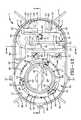
- FIG. 5is a plan view of the inside surface of the housing top cover plate.
- FIG. 6is a plan view of the underside surface of the locking disc component of the ratchet mechanism.
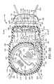
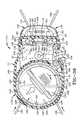
- FIG. 7is a sectional view of the security device in locked position taken beneath the top cover plate.
- FIG. 7Ais a fragmentary view of the pivot arm component of the locking mechanism shown engaged with the locking disc shown in dot dashed lines.
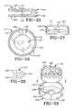
- FIG. 8is a bottom plan view of the security device showing the tensioning of the internal spool tension spring.
- FIG. 9is an enlarged sectional view taken on line 9 - 9 , FIG. 7 .
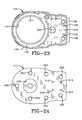
- FIG. 10is an enlarged sectional view taken on line 10 - 10 , FIG. 7 showing the lock mechanism in locked position.
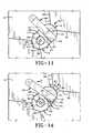
- FIG. 11is a top plan view similar to FIG. 1 showing the unlocking key engaged with the security device.
- FIG. 12is a sectional view similar to FIG. 7 showing the locking mechanism in the locked position with the key engaging the lock mechanism just prior to the key being moved to the unlocked position.
- FIG. 13is a sectional view taken on line 13 - 13 , FIG. 12 .
- FIG. 14is a top plan view similar to FIG. 11 showing the unlocking key being moved to the unlocked position.
- FIG. 15is a sectional view similar to FIG. 12 showing the locking mechanism in the unlocked position and the ratchet mechanism and cable clip in disengaged positions.
- FIG. 16is a sectional view taken on line 16 - 16 in FIG. 15 showing the locked mechanism in the unlocked position.
- FIG. 17is a plan view similar to FIG. 1 showing the security device being placed on a package and the cable clip being unwound from the spool for placement about the package.
- FIG. 18is a view similar to FIG. 17 showing the cable clip being inserted into the housing of the security device after the cable is placed about the package.
- FIG. 19is a perspective view of the unlocking key.
- FIG. 20is a fragmentary top plan view with portions broken away showing a modified embodiment of the cable attachment clip connection.
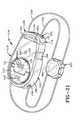
- FIG. 21is a diagrammatic top perspective view of a second embodiment of the security device of the present invention.
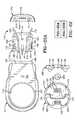
- FIG. 22is a combination of FIGS. 22A and 22B which are plan views of the major components of the security device of FIG. 21 .
- FIG. 23is a plan view of the inside of the top housing component.
- FIG. 24is a plan view of the outside of the bottom housing component.
- FIG. 25is a side elevational view of the spool of the modified security device of FIG. 21 .
- FIG. 26is a bottom plan view of the spool of FIG. 25 .
- FIG. 27is an end view of the clip housing of the modified security device.
- FIG. 28is a top plan view of the locking lever of the locking mechanism of the modified security device.
- FIG. 29is an exploded perspective view of the coiled tensioning spring removed from its holder.
- FIG. 30is a top plan view of the security device of FIG. 21 with the locking clip being disconnected from the housing.
- FIG. 31is an enlarged fragmentary sectional view taken on line 31 - 31 , FIG. 30 .
- FIG. 32is a fragmentary sectional view showing the clip being moved from the position of FIG. 31 into engagement within the end of the housing of the security device.
- FIG. 33is a fragmentary top plan view with portions in section similar to FIG. 30 showing the clip moving into a first locked position with the housing.
- FIG. 34is a fragmentary sectional view taken on line 34 - 34 , FIG. 33 .
- FIG. 35is a sectional view taken on line 35 - 35 , FIG. 33 .
- FIG. 36is a fragmentary top plan view with portions in section similar to FIG. 33 showing the clip in a fully locked position within the housing of the security device.
- FIG. 37is a fragmentary sectional view taken on line 37 - 37 , FIG. 36 .
- FIG. 38is a sectional view taken on line 38 - 38 , FIG. 36 , showing the clip in a fully locked position within the housing and the cable in a wound position about the spool.
- FIG. 39is a top plan view with portions in section showing the actuation button in a depressed condition and the spool winding the cable into the housing.
- FIG. 40is a sectional view similar to FIG. 35 showing the magnetic key unlocking the clip from the housing.
- Security device 1includes a main housing indicated generally at 5 ( FIG. 4 ), and a plurality of cables 7 , preferably two, which are stored on an internal spool 8 .
- Housing 5( FIG. 4B ) includes a main housing body 9 preferably formed by an oval shape side wall 10 , with an internal spool compartment 11 and a lock compartment 13 .
- Housing 5further includes a top cover plate 15 ( FIGS. 4A and 5 ) which is secured on the top peripheral edge of the housing body 9 by a plurality of fasteners 17 .
- One end of the double cable 7is connected to internal spool 8 with the other ends being connected to an attachment clip 19 .
- Cable 7is stored on spool 8 which is trapped within and rotatably contained within spool compartment 11 formed by oval shaped side wall 10 and curved wall 57 , and retained therein by top plate 15 .
- a winder post 21( FIG. 9 ) extends through a circular hole 22 formed in spool 8 and is used to pretension a clock spring 23 , preferably at the time of manufacture, which provides a bias on spool 8 to rotate it in the winding direction for retracting the cable onto the spool in a storage position as shown in FIG. 9 and discussed further below.
- Spool 8has spaced flanges 25 and 26 and an intervening wall 31 which form a cable storage area therebetween.
- An annular ring 27 of one way gear teeth 28is mounted on upper spool 26 and forms part of the ratchet mechanism for controlling the rotational movement of the spool within housing 5 .
- Clock spring 23is located within the annular interior of a tensioning member 29 ( FIG. 4A ) which includes a cross bar 30 for manually rotating member 29 to tension the cable after being placed about package 3 .
- One end 93 of clock spring 23is connected to winder post 21 with another end being connected to spool 8 .
- One type of connectionmay be by a projection 33 ( FIG. 4B ) attached to spring 23 which extends through a slot 34 formed in the cylindrical side wall of member 29 and into a slotted opening 96 formed in the spool wall 31 .
- Tensioning member 29is connected to spool 8 by a plurality of snap-fit projections 24 which extend into slots 32 formed in spool 8 .
- Cables 7exit through a pair of holes 36 formed in side wall 10 of housing body 9 as shown in FIG. 2 , and have a pair of positioning ball stops 38 attached thereto.
- the ratchet mechanismincludes a locking disc indicated generally at 35 ( FIG. 4A ), which has a generally circular configuration at one end formed with a central circular opening 37 into which a plurality of flexible locking pawls 39 extend in an arcuate cantilever fashion. Each locking pawl has a camming projection or post 41 formed on the distal end thereof adjacent a series of gear teeth 43 .
- Locking disc 35has a generally rectangular-shaped segment 45 at the end of the locking disc opposite end 35 which is formed with a pair of tapered recesses 47 for receiving a pair of locking tines 49 to secure locking disc 35 in the locked position as discussed further below.
- Tines 49preferably are formed integrally from a metallic locking strip 51 are biased outwardly therefrom and secure locking disc 35 in a locked non-rotatable position as shown particularly in FIGS. 7 , 9 and 10 .
- Locking disc 35is attached to inside surface 46 of housing cover plate 15 by three curved projections 48 formed on cover plate 15 which snap fit engage the interior periphery of circular opening 37 of the locking disc ( FIG. 9 ).
- Annular ring 27 of spool 8extends upwardly through circular opening 37 of locking disc 35 with gear teeth 43 of locking pawls 39 being engageable with gear teeth 28 of ring 27 as shown in FIG. 7 due to the flexible cantilever arrangement of locking pawls 39 .
- Locking disc 35also rests against three curved bosses 52 which are formed on and project from surface 46 of plate 15 into which posts 41 of locking pawls 39 extend.
- Housing top cover plate 15( FIG. 5 ) is formed with a circular opening 59 for rotatably receiving tensioning member 29 therein providing accessibility to cross member 30 .
- Cover plate 15also includes a pair of key-receiving slots 61 which have an elongated configuration and which align with key recesses 53 of locking disc 35 .
- a key positioning ledge 63is formed on the outer surface of cover plate 15 to assist in aligning and positioning a pair of key projections 65 of a magnetic key 66 ( FIG. 19 ) when placed thereon as shown in FIGS. 11 and 13 for unlocking locking tines 49 from locking engagement within recesses 47 of locking disc 35 as discussed further below.
- the unique locking mechanism of the present inventionincludes a pivotally mounted lock arm indicated generally at 69 ( FIG. 4B ), which includes a curved end 71 and an opposed end 72 and an intervening pivot 73 .
- End 72is formed with a arcuate section of ratchet teeth 74 with end 71 being formed with a pair of bosses 75 extending downwardly therefrom.
- Lock arm 69is pivotally mounted on the top end of a post 77 located in lock compartment 13 which extends into an opening which forms pivot 73 , which when assembled will place ratchet teeth 74 in mating engagement with an arcuate segment of ratchet teeth 78 formed on the bottom surface of end 45 of locking disc 35 as shown in FIG. 6 .
- Lock arm 69rests upon and is supported by an annular shoulder 70 formed on pivot post 77 and retained in position by an arcuate projection 67 and an annular boss 68 extending from on the inside surface of plate 15 ( FIGS. 5 and 9 ). The extended end of pivot post 77 is received within boss 68 . Arm 69 also is supported by a pair of ribs 62 formed along wall 57 ( FIG. 4B ). Bosses 75 extend through a pair of curved openings 79 formed in a ledge 76 formed adjacent an end of sidewall 9 for releasable engagement with a pair of angled slots 80 formed in an end of attachment clip 19 ( FIG. 4B ). Attachment clip 19 is adapted to be inserted into an arcuate-shaped opening 83 formed in an end of housing wall 10 when in an engaged locked position for securing the cable about package 3 .
- a piezo alarm 85is mounted in lock compartment 13 and is operatively engaged with a printed circuit board 87 also mounted in compartment 13 which is powered by a battery (not shown) which is accessible through a battery cover 88 formed in the bottom of housing body 9 as shown in FIG. 8 .
- An EAS tag 90preferably will be located in lock compartment 13 and operationally connected and controlled by printed circuit board 87 .
- the alarm system provided by printed circuit board 87 and alarm 85may implement different types of EAS tags 90 such as acoustio-magnetic (AM), electro-magnetic (EM) and radio frequency (RF) within the concept of the invention.
- EAS tags 90such as acoustio-magnetic (AM), electro-magnetic (EM) and radio frequency (RF) within the concept of the invention.
- an electrical sense loopwill be provided by cables 7 so that should one of the cables be cut or separated from the security device, the alarm system will actuate audible piezo alarm 85 .
- EAS tag 90is intended to actuate an audible alarm or other signaling device at a security gate should a thief attempt to remove the protected article with the security device attached thereto in an unauthorized manner through the exit protected security gate.
- the alarm system and components thereofare well known in the security art and thus are not described in further detail.
- spool 8When in the assembled position, spool 8 is rotatably mounted within housing 5 on winder post 21 and cable 7 is stored thereon with two of the cables extending outwardly through holes 36 ( FIG. 2 ) and terminating at clip 19 .
- Spool 8is rotatably mounted on winder post 21 which extends through a complementary-shaped hole 91 formed in the bottom wall of housing 5 and through hole 22 in the spool.
- a pair of arcuate projections 92FIG. 4B ) surround hole 91 and form a pair of slots 99 .
- clock spring 23is pretensioned by winder post 21 .
- One end 93 of clock spring 23is inserted into a slot 95 formed in winder post 21 with another end of the clock spring being fixed to spool 8 by projection 33 extending through slot 34 of tensioning member 29 and into slotted opening 96 formed on wall 31 of spool 8 as discussed above.
- Winder post 21will be partially inserted into hole 91 and spool hole 22 and then rotated a predetermined number of revolutions to pretension clock spring 23 to a desired tensioning force.
- Post 21then is inserted fully into hole 91 wherein a pair of wings 98 formed on the bottom of post 21 are inserted into notches 99 to lock post 21 in its final installed position with the desired tension being applied to spring 23 which exerts a predetermined rotational force on spool 8 .
- One-way gear teeth 43 of locking pawls 39will be in locking engagement with gear teeth 28 of spool ring 27 when device 1 is in the locked position as shown in FIG. 7 , and disengaged therefrom when in the unlocked position of FIG. 15 as described further below.
- FIGS. 7-18The manner of operation of the improved cable wrap security device of the present invention is best shown in FIGS. 7-18 .
- spool 8When in the unlocked and unattached position as shown in FIG. 17 , spool 8 will be free wheeling in the unwind direction.
- a clerkwill pull outwardly on clip 19 as shown by Arrow A, which will unwind cable 7 from about spool 8 .
- the cableis placed about the corners of the package until clip 19 reaches the position as shown in FIG. 18 where the clip is at the entrance of end slot opening 83 .
- a clerkwill insert clip 19 into opening 83 as shown by Arrow B, which will cause bosses 75 of lock arm 69 , which are aligned with the entrances to angled slots 80 of clip 19 , to move in an angular fashion along angled slots 80 .
- clip 19is prevented from being disengaged from housing 5 due to the angular position of locking arm bosses 75 and angled slots 80 .
- Arm 75is prevented from further movement due to the engagement of ratchet teeth 74 with ratchet teeth 78 of locking disc 35 , since disc 35 is prevented from further movement due to the engagement of locking pawl gear teeth with the one-way gear teeth 28 of spool 26 and locking tines 49 engaged in recesses 47 .
- Locking arm 69is prevented from movement since it is secured at one end by clip 19 and at the other end by ratchet teeth 74 , which in turn positively engages pawl teeth 43 of locking disc 39 with spool teeth 28 .
- the engagement of pawl teeth 43 with spool teeth 28prevents any further rotation of the spool in the cable discharge or unwind direction.
- a clerkwill place key 66 against key positioning ledge 63 and place projections 65 through elongated slot 61 and into recesses 53 of locking disc 35 which will align a pair of internal magnets 103 with each of the locking tines 49 . See FIGS. 11 and 13 .
- the locking tineswill be attracted to magnets 103 and move out of engagement within recesses 47 from the locked position of FIG. 10 to the unlocked position of FIG. 13 .
- the operatorthen merely moves the key a very slight amount along cover plate 15 as shown by Arrow D, FIG. 14 , with key projections 65 moving slightly along slotted openings 61 .
- the locking device of the present inventionprovides for a cable wrap security device which is easily placed in a secured locked position about a package by pulling the cables out of their retracted position within the device overcoming the biasing force exerted by clock spring 23 .
- the locking deviceautomatically becomes locked by insertion of clip 19 into housing 5 , as well as automatically actuating the ratchet mechanism preventing rotation of the spool and consequently the attached cable in a payout or unwind direction.
- slight manual rotation of the exposed end of tensioning member 29will further retract the cable by winding spool 8 in a further cable take-up direction until the desired tension is achieved on the cable about the package to prevent its removal from about the package until the device is unlocked by a special key, such as magnetic key 66 .
- FIG. 20shows an alternate embodiment of the connection of cable 7 with clip 19 wherein a first embodiment is shown particularly in FIG. 15 .
- cable 7merely forms a continuous loop through clip 19 , which although providing a strong mechanical connection between the cable and the clip, does not provide the additional security as that provided by the alternate connection of cable 7 to clip 19 as shown in FIG. 20 and described below.
- cable 7is two separate cables, each of which terminates in a slightly enlarged connector 105 , which may be press fitted on the ends of the cable which are received and retained within slots 107 formed in both sides of clip 19 .
- Cable connectors 105are each engageable with a spring clip 109 which provides an electrical terminal through its connection to the appropriate circuitry formed on printed circuit board 87 .
- cable terminal connectors 105will mechanically engage spring clips 109 completing an electrical circuit through printed circuit board 87 .
- clip 19should clip 19 be forcibly pulled out from housing 9 , it will disrupt the electrical continuity established through printed circuit board 87 causing alarm 85 to sound, notifying the store personnel that an unauthorized event has occurred.
- a modified security device of the present inventionis indicated generally at 110 , and is shown particularly in FIGS. 21-40 .
- Modified security device 110includes a main housing indicated generally at 113 , comprised of an upper housing member 114 and a bottom housing member 115 which can be joined to together by adhesives, sonic welding etc. to form an internal chamber having a spool compartment 116 in which is rotatably mounted a cable spool 117 , and a lock compartment 118 .
- Top housing member 114is shown particularly in FIG. 22A and has an elongated configuration with a main circular opening 119 in which is rotatably mounted a winder mechanism 121 .
- Winder mechanism 121is operationally connected to cable spool 117 by a plurality of projections 122 formed on spool 117 and extending into notches 123 formed in the periphery of an annular flange 125 .
- Winder mechanism 121includes the outer substantially annular flange 125 which is located beneath a downwardly extending annular projection 127 surrounding housing opening 119 ( FIG. 38 ) to retain winder mechanism 121 within spool compartment 116 of housing 113 .
- Winder mechanism 121includes a flip-up handle 129 which is pivotally mounted by a pair of pivot pins 130 on the main disc-shaped body portion 131 of the winder mechanism. Winder mechanism 121 is secured to cable spool 117 by projections 122 so as to be rotatable therewith.
- a cable 133which could be a single loop or a pair of cables is connected to spool 117 with the other cable ends being connected to an attachment clip indicated generally at 135 .
- Cable 133is stored on spool 117 which is rotatably mounted within spool compartment 116 on a post 139 extending upwardly from a circular plate 137 ( FIGS. 22B , 24 and 38 ) which is mounted in a circular hole 138 formed in bottom housing member 115 .
- Post 139is formed with a slot 141 in which an end 142 of a coil spring 143 is secured which provides a biasing force on spool 117 to rotate the spool in the winding direction to retract the cable onto the spool into a stored position as shown in FIGS.
- Spool 117has spaced flanges 145 and 146 ( FIGS. 22B and 25 ) and an intervening wall 147 which forms a cable storage area therebetween.
- the use of only two cables or cable loops attached to spool 117 and exiting housing 113is an improvement over prior cable security devices such as shown in U.S. Pat. No. 5,722,266 which has four cable loops or sections exiting the housing. This reduces tangling of the cable and enables a greater take-up tension to be placed on the two cable loops than possible on the four cable loops when manually rotating the spool after placement of the cable about the object.
- a plurality of notches 144may be formed in wall 147 for securing cable 133 to the spool.
- a plurality of gear teeth 149preferably are formed on the outer periphery of both spool flanges 145 and 146 and form part of a ratchet mechanism for controlling the rotational movement of spool 117 within spool compartment 116 .
- Coil spring 143is seated within a cylindrical spring holder 151 ( FIG. 29 ) which has a center hole 152 formed in a bottom wall 153 through which spool post 139 extends as shown in FIG. 38 .
- Holder 151is clamped against housing bottom member 115 by spool flange 145 .
- a second end 155 of spring 143is inserted into a slot 156 formed in spring holder sidewall 157 ( FIG. 22B ) to secure spring 143 to spring holder 151 .
- Winder mechanism 121 as discussed aboveis fixed to spool 117 and is manually rotated as discussed further below, by the use of flip-up handle 129 for rotating spool 117 in a clockwise direction as shown by Arrow A in FIG. 33 to tighten cable 133 about a product after retracting the cable into housing 113 by the biasing force of spring 143 .
- Cable 133exits housing 113 through a pair of holes 159 formed in one end of elongated sidewall 160 of top housing member 114 .
- a ratchet mechanism which engages spool teeth 149 to prevent movement of the spool in the unwinding directionincludes a spring biased spool locking lever 162 ( FIGS. 22B and 28 ) which is biased by U-shaped spring 163 into engagement with the spool gear teeth formed on spool flanges 145 and 146 .
- Locking lever 162is pivotally mounted within spool compartment 116 as shown in FIG. 39 by a pivot pin 165 and biased toward engagement with the spool teeth.
- a pair of spaced projections 166are formed on one end of locking lever 162 which engage the pair of spaced gear teeth on flanges 145 and 146 as shown in FIG. 30 .
- the use of the pair of gear teeth and a pair of projections 166provide increased resistance to tampering by a thief and increased security projections to security device 110 since it is able to withstand greater tension on the attached cables.
- a release button 169( FIGS. 22B and 30 ) is pivotally mounted in spool compartment 116 by pivot pin 165 .
- Release button 169includes an outwardly projecting pawl 171 on the opposite end from the pivot, the function of which is discussed further below.
- attachment clip 135( FIG. 22A ) includes a locking clip indicated generally at 173 and a clip housing 174 .
- Cable 133is shown as being two cable sections which are secured in locking clip 173 by a pair of metallic ferrules 175 .
- Ferrules 175are attached to the ends of cables 133 and seated in compartments 167 formed in clip 173 to secure the cables in one end of locking clip 173 .
- Cables 133extend outwardly through an elongated slot 177 ( FIG. 27 ) formed in end wall 178 of clip housing 174 .
- Locking clip 173has a generally planar rectangular configuration and is divided by a slot 170 into a pair of legs 168 .
- Each legis formed with a first pair of spaced recesses 179 ( FIGS. 22A and 31 ), each of which terminates in an upwardly extending tapered rear wall 180 opposite a right angled shoulder 184 , and has a second pair of recesses 181 spaced rearwardly from recess 179 .
- the front edges of locking clip legs 168have tapered surfaces 183 adjacent the first pair of recess 179 . The function of these recesses and angled surfaces are discussed further below with respect to the placement and locking of attachment clip 135 within lock compartment
- a locking mechanism indicated generally at 185is mounted at the attachment clip entrance end 186 of housing 113 .
- Entrance end 186is formed with a slotted opening 187 formed by an outwardly extending rectangular frame 188 ( FIG. 31 ) for slidably receiving locking clip 173 therein as discussed further below.
- Locking mechanism 185includes a locking shuttle 189 having a pair of spaced locking plungers 190 preferably formed of a magnetically attractable material such as metal, having end locking projections 191 which are engageable in recesses 179 and 181 of locking clip 173 to dock attachment clip 135 to housing 113 .
- Shuttle 189has a concave recess 188 which provides clearance from a battery 199 when in the locked position.
- a pair of coil springs 193are mounted about a pair of posts 195 which are formed integrally on the inside surface of top housing member 114 ( FIGS. 23 and 35 ) and which extend into aligned holes 197 formed in locking shuttle 189 ( FIGS. 22A and 35 ). Springs 193 bias locking shuttle 189 , and in particular, locking plunger ends 191 into locking engagement with recesses 179 and 181 of locking clip 173 .
- Modified security device 110includes piezo alarm 85 which is located within lock compartment 118 , and is operatively engaged with printed circuit board 87 powered by battery 199 ( FIG. 38 ).
- a light pipe 200( FIG. 38 ) may be mounted in a hole 202 formed in top housing member 114 , adjacent an LED 201 mounted on circuit board 87 , which is lighted when the alarm circuitry formed on printed circuit board 87 is activated upon attachment clip 135 , and in particular, locking clip 173 being in its final locking position as shown in FIGS. 21 , 35 , 36 , 37 and 38 .
- ferrules 175which are mounted on the ends of cables 133 , engage electrical contacts 203 which extend downwardly from printed circuit board 87 and are electrically connected thereto to complete the alarm circuit of printed circuit board 87 through cables 133 by the electrical connection between contacts 203 and ferrules 175 .
- Thisprovides for the sense loops extending through cables 133 .
- An EAS tagcould be mounted within lock compartment 118 or at other locations within device 110 if desired to add additional security to the device.
- a cable crossover pad 205may be mounted on cables 133 and is generally located on an opposite side of a package from that of security device 110 .
- Pad 205assists in maintaining the cables about the protected package or other item making it more difficult to slip the cable off of the edges of the package.
- Pad 205can also contain some of the alarm circuitry contained in housing 113 indicated at 206 . By placing some of the electronics of the alarm circuitry in crossover pad 205 it can reduce the size and complexity of security device 110 .
- the EAS tagcould also be placed easily in or on crossover pad 205 if desired.
- FIGS. 30-40The manner of operation of the modified security device 110 is best shown in FIGS. 30-40 .
- a clerkWhen in the unlocked position as shown in FIG. 30 , a clerk will depress button 169 such as shown in FIG. 33 which will pivot locking lever 163 in a counterclockwise direction since surface 216 of button 169 is abuttingly engaged with surface 217 of lock lever 162 ( FIG. 22B ).
- This pivotal movement of locking lever 162will disengage projections 166 from gear teeth 149 placing spool 117 in a free wheeling condition in the unwind direction.
- a clerkwill pull outwardly on attachment clip 135 which will overcome any bias of spring 143 on spool 117 and unwind a sufficient amount of cable 133 from about spool 17 enabling the cable to be placed about the corners of the package until clip 135 reaches the position as shown in FIG. 30 where attachment clip 135 is at entrance slot opening 187 .
- This unwinding of cable 133 from spool 117will further tension spool spring 143 tending to wind cable 133 on the spool.
- U-spring 163will bias locking lever 162 and projections 166 thereof back into locking engagement with gear teeth 149 .
- the clerkwill then insert clip 135 into slot opening 187 from the unlatched and unlocked position of FIGS.
- locking projections 190are initially raised upwardly as they move along upwardly tapered surfaces 180 , after which they automatically drop into locking recesses 181 where they are prevented from backward movement by vertical wall or shoulder 184 .
- ferrules 175engage electric contacts 203 of printed circuit board 87 providing an electrical path through the conductors of cable 133 and the alarm circuit providing sense loops through the cables so that piezo alarm 85 will sound should cable 133 be severed by a potential thief.
- depression of button 169was removed whereupon U-spring 163 biased locking lever 162 inwardly so that locking projections 166 enter into the adjacent gear teeth 149 as shown in FIG. 30 .
- pawl 171 of button 169When in this locked position, pawl 171 of button 169 is located adjacent side edge 207 of locking clip 173 ( FIG. 36 ), which prevents depression of button 169 inwardly, preventing the removal of locking projections 166 from within gear teeth 49 .
- the cableis tensioned about the package by the force exerted on cable 133 by coil spring 143 .
- the clerkmerely raises up flip-up handle 129 of winder mechanism 121 and manually rotates the winder mechanism attached to spool 117 in a clockwise direction as shown by Arrow A, FIG. 39 to further tighten the cable about the package to a desired tension.
- the cablewill move in the tightening or windup direction since locking lever 162 can pivot in a counterclockwise direction as shown in FIG. 39 , but not in a clockwise direction when engaged with spool teeth 149 due to the abutment of locking lever surface 217 with button surface 216 .
- Button 169is prevented from inward movement by the engagement of pawl 171 with side edge 207 of locking clip 173 .
- the contact between ferrules 175 and printed circuit board contacts 203will activate the alarm circuitry and light LED 201 which is visible to a clerk and potential thief through light pipe 200 .
- magnetic key 66( FIG. 19 ) is properly placed on the top surface of clip housing 174 by inserting locating projections 65 into alignment holes 211 formed in clip housing 174 .
- This alignmentensures that magnets 103 are properly aligned with locking plungers 190 as shown in FIG. 40 .
- Magnets 103will move locking plungers 190 from their locked position of FIG. 35 to the unlocked position of FIG. 40 as shown by Arrows E.
- clip 173is easily removed from housing 113 by sliding the locking clip out through slot opening 187 .
- shuttle 189upon the upward movement of plungers 190 and shuttle 189 by the attraction toward magnets 103 , shuttle 189 will engage and depress a switch 210 mounted on printed circuit board 87 ( FIGS. 32 and 37 ) which will deactivate the alarm circuitry preventing the sounding of the alarm upon removal of clip 135 from housing 113 .
- pawl 171is disengaged from side edge 207 of locking clip 173 whereupon button 169 can be depressed which will disengage locking projections 166 from within spool teeth 149 which will automatically retract the cables back into the housing and about spool 117 due to the biasing force exerted thereon by spring 143 .
- a clerkmerely removes attachment clip 135 from within housing 113 after placing key 66 therein and by depression of release button 169 will control the windup of the cable back into the housing about the spool until clip 135 reaches a position closely adjacent the opposite end of housing 113 from that of the entrance end 186 , or until crossover pad 205 engages the end of housing 113 if a pad 205 is used with security device 110 .
- This automatic retraction of the cable back into the housingprevents excess cable from remaining dangling from housing 113 , which heretofore became tangled with adjacent products or other security devices and cables.
- the alarm systemprovides the desired security preventing cable 133 from being severed without sounding the internal alarm and enables the cable to be tightened about the product to the desired tension by easily manually rotating flip-up handle 129 .
- crossover pad 205may or may not be used with modified security device 110 and it may or may not include portions of the alarm circuitry or contain an EAS tag therein as discussed above.
- a slight gap 213may be formed between the inner edge 214 of clip housing 174 which enables attachment clip 135 to be manually moved slightly inwardly in the direction of Arrow F as shown in FIG. 37 , when a clerk starts to unlock security device 110 and remove attachment clip 135 from the housing.
- This slight inward movementfacilitates the upward movement of locking plungers 190 by eliminating the friction force created between the edge of locking plunger end 191 with recess shoulder 184 , which heretofore was tightly clamped together by the tension of the coil spring attempting to pull attachment clip 135 out of engagement from within housing 113 .
- attachment clip 135pushes slightly inwardly on attachment clip 135 to reduce the pressure between the locking plungers and the locking clip until the locking plungers have been retracted facilitating the unlocking and removal of the attachment clip from within the housing.
- the use of only two cables around spool 117 or one continuous cable loopenables a tighter winding of the cables on the spool and less force on the locking lever and results in considerably less tangling of cables as occurs when four separate cables are used as in prior cable wrap security devices.
- housing 113provides a device which is more easily gripped by a clerk than when the security device is circular, since it remains in a constant gripped position within the hand of the clerk to further facilitate the winding and unwinding of the cable from the spool upon depression of button 169 .
- piezo alarm 85is located closely adjacent bottom housing member 115 as shown in FIG. 38 and a plurality of speaker holes 215 ( FIG. 22B ) to provide protection from a potential thief who could attempt to gain access to the speaker and electronics through the speaker holes if the holes were exposed on top of the security device.
- Simulated speaker holes 220may be formed in disc 131 indicating to a thief that an alarm may be contained in the housing.
- small standoff feet or projections 222preferably extend from the bottom surface of bottom housing member 115 providing better sound transmissions from alarm 85 when actuated by providing a gap or spacing between the speaker holes and secured object.
- attachment clip 135it is also possible in accordance with the present invention, to form attachment clip 135 as two separate clips, each of which is attached to one of a pair of cables and individually inserted through end openings in the housing and locked by a locking mechanism similar to that described above. This enables at least one of the cables to be inserted through a small opening of a product being protected thereby which would provide protection to that product without requiring the product being a box or a similar parallelepiped configuration. Likewise, it is understood that attachment clip 135 can be inserted through openings in a product before being latched to housing 113 providing a security device having an alarm which could secure the product to a support structure or the like.
- security device 110is that upon a large force being exerted on cable 133 , the cable can be pulled away from ferrules 175 ( FIG. 30 ) or the ferrules will break electrical contact with contacts 203 ( FIG. 37 ) causing alarm 85 to be actuated.
- the attachment of only two cable loops or cable sections to the attachment clip which is detached from the housing when in the unlocked positionenables the cables to be retracted into the housing until needed, eliminating exposed cables susceptible to tangling as occurs in prior art cable wrap security devices.
- the retraction spring mechanismenables cable slack to be easily taken up after placing the cable about an object prior to manually tightening the cable, and after the cable has been removed from a protected object.
- lockor “locked” as used in this description means that a key of some type is required to change the state from locked to unlocked to distinguish from the term “latched” to describe a connection between two elements where a key is not required to undo the elements.
Landscapes
- Physics & Mathematics (AREA)
- General Physics & Mathematics (AREA)
- Engineering & Computer Science (AREA)
- Automation & Control Theory (AREA)
- Computer Security & Cryptography (AREA)
- Electromagnetism (AREA)
- Burglar Alarm Systems (AREA)
Abstract
Description
Claims (18)
Priority Applications (2)
| Application Number | Priority Date | Filing Date | Title |
|---|---|---|---|
| US13/298,385US8281626B2 (en) | 2007-03-28 | 2011-11-17 | Cable wrap security device |
| US13/471,696US9487970B2 (en) | 2007-03-28 | 2012-05-15 | Cable wrap security device |
Applications Claiming Priority (3)
| Application Number | Priority Date | Filing Date | Title |
|---|---|---|---|
| US92054607P | 2007-03-28 | 2007-03-28 | |
| US12/027,296US8122744B2 (en) | 2007-03-28 | 2008-02-07 | Cable wrap security device |
| US13/298,385US8281626B2 (en) | 2007-03-28 | 2011-11-17 | Cable wrap security device |
Related Parent Applications (1)
| Application Number | Title | Priority Date | Filing Date |
|---|---|---|---|
| US12/027,296ContinuationUS8122744B2 (en) | 2007-03-28 | 2008-02-07 | Cable wrap security device |
Related Child Applications (1)
| Application Number | Title | Priority Date | Filing Date |
|---|---|---|---|
| US13/471,696Continuation-In-PartUS9487970B2 (en) | 2007-03-28 | 2012-05-15 | Cable wrap security device |
Publications (2)
| Publication Number | Publication Date |
|---|---|
| US20120055209A1 US20120055209A1 (en) | 2012-03-08 |
| US8281626B2true US8281626B2 (en) | 2012-10-09 |
Family
ID=39788810
Family Applications (4)
| Application Number | Title | Priority Date | Filing Date |
|---|---|---|---|
| US12/027,296Active2030-01-28US8122744B2 (en) | 2007-03-28 | 2008-02-07 | Cable wrap security device |
| US12/634,875Active2030-11-30US8599022B2 (en) | 2007-03-28 | 2009-12-10 | Cable wrap security device |
| US12/983,564Active2031-01-31US9447611B2 (en) | 2007-03-28 | 2011-01-03 | Cable wrap security device |
| US13/298,385ActiveUS8281626B2 (en) | 2007-03-28 | 2011-11-17 | Cable wrap security device |
Family Applications Before (3)
| Application Number | Title | Priority Date | Filing Date |
|---|---|---|---|
| US12/027,296Active2030-01-28US8122744B2 (en) | 2007-03-28 | 2008-02-07 | Cable wrap security device |
| US12/634,875Active2030-11-30US8599022B2 (en) | 2007-03-28 | 2009-12-10 | Cable wrap security device |
| US12/983,564Active2031-01-31US9447611B2 (en) | 2007-03-28 | 2011-01-03 | Cable wrap security device |
Country Status (7)
| Country | Link |
|---|---|
| US (4) | US8122744B2 (en) |
| JP (1) | JP5378347B2 (en) |
| CN (1) | CN101663450B (en) |
| AU (1) | AU2008230097B2 (en) |
| CA (1) | CA2719521C (en) |
| MX (1) | MX2009010341A (en) |
| WO (1) | WO2008118301A1 (en) |
Cited By (19)
| Publication number | Priority date | Publication date | Assignee | Title |
|---|---|---|---|---|
| US20100038431A1 (en)* | 2008-08-13 | 2010-02-18 | B&G International, Inc. | Security hang tag with swivel head |
| US20100231388A1 (en)* | 2009-03-12 | 2010-09-16 | Checkpoint Systems, Inc. | Disposable cable lock and detachable alarm module |
| US20110094274A1 (en)* | 2007-03-28 | 2011-04-28 | Checkpoint Systems, Inc. | Cable wrap security device |
| US20110215683A1 (en)* | 2009-06-22 | 2011-09-08 | Kabushiki Kaisha San-Ei | Antitheft device for a product display case |
| US20110283750A1 (en)* | 2010-04-30 | 2011-11-24 | Checkpoint Systems, Inc. | Security assembly for attachment to an object |
| US20110308283A1 (en)* | 2008-07-22 | 2011-12-22 | Thomas Nilsson | Alarm device |
| US20120085134A1 (en)* | 2010-10-04 | 2012-04-12 | Checkpoint Systems Inc. | Adjustable cable security device |
| US20130067968A1 (en)* | 2010-05-13 | 2013-03-21 | Checkpoint Systems, Inc. | Cable ratchet security device |
| US20140318192A1 (en)* | 2008-02-07 | 2014-10-30 | Checkpoint Systems, Inc. | Cable wrap security device |
| US9487970B2 (en) | 2007-03-28 | 2016-11-08 | Checkpoint Systems, Inc. | Cable wrap security device |
| US9816297B2 (en) | 2015-12-14 | 2017-11-14 | Checkpoint Systems, Inc. | Security device with multiple control states |
| US9953498B2 (en) | 2013-11-18 | 2018-04-24 | Invue Security Products Inc. | Wrap for an item of merchandise |
| US10352068B2 (en) | 2017-02-07 | 2019-07-16 | Master Lock Company Llc | Cable locking device |
| US10529207B1 (en) | 2019-01-08 | 2020-01-07 | Xiao Hui Yang | EAS device with elastic band |
| USD890618S1 (en) | 2018-02-27 | 2020-07-21 | Invue Security Products Inc. | Cable wrap |
| US20220207975A1 (en)* | 2020-12-25 | 2022-06-30 | Industrial Security Solutions, Corp. | Novel smart anti-theft tag with quadruple alarm function |
| US11455508B2 (en) | 2020-12-07 | 2022-09-27 | Industrial Security Solutions, Corp. | Smart anti-theft tag for boots |
| US11459800B2 (en) | 2017-05-25 | 2022-10-04 | Invue Security Products Inc. | Package wrap |
| US20240426143A1 (en)* | 2023-06-23 | 2024-12-26 | Industrial Security Solutions, Corp. | Slide shoe tag |
Families Citing this family (60)
| Publication number | Priority date | Publication date | Assignee | Title |
|---|---|---|---|---|
| US7428833B2 (en)* | 2004-12-22 | 2008-09-30 | Peak Recreational Products, Llc | Vehicle mountable personal property lock assembly |
| US7168275B2 (en)* | 2004-12-28 | 2007-01-30 | Alpha Security Products, Inc. | Cable wrap security device |
| US7659817B2 (en)* | 2005-11-29 | 2010-02-09 | Checkpoint Systems, Inc. | Security device with perimeter alarm |
| US9404291B1 (en)* | 2015-03-04 | 2016-08-02 | Checkpoint Systems, Inc. | Device and method for an alarming strap tag |
| US7715679B2 (en) | 2007-05-07 | 2010-05-11 | Adc Telecommunications, Inc. | Fiber optic enclosure with external cable spool |
| US7756379B2 (en) | 2007-08-06 | 2010-07-13 | Adc Telecommunications, Inc. | Fiber optic enclosure with internal cable spool |
| US8228192B2 (en)* | 2008-05-30 | 2012-07-24 | Checkpoint Systems, Inc. | Cable lock closure with defeat prevention |
| USD599693S1 (en)* | 2008-08-27 | 2009-09-08 | Sayegh Adel O | Theft deterrent tag having crossing lanyard for use with articles |
| US8542119B2 (en)* | 2009-01-13 | 2013-09-24 | Invue Security Products Inc. | Combination non-programmable and programmable key for security device |
| EP2496781A2 (en)* | 2009-11-02 | 2012-09-12 | Checkpoint Systems, Inc. | Adjustable dual loop cable security device |
| US10232150B2 (en) | 2010-03-11 | 2019-03-19 | Merit Medical Systems, Inc. | Body cavity drainage devices and related methods |
| US8837940B2 (en) | 2010-04-14 | 2014-09-16 | Adc Telecommunications, Inc. | Methods and systems for distributing fiber optic telecommunication services to local areas and for supporting distributed antenna systems |
| CH703299A1 (en)* | 2010-06-07 | 2011-12-15 | Pataco Ag Ind Und Unterhaltungselektronik | Safety device for objects. |
| AU2010355632B2 (en) | 2010-06-18 | 2014-09-18 | Adc Communications (Shanghai) Co., Ltd. | Fiber optic distribution terminal and method of deploying fiber distribution cable |
| CN110174737A (en) | 2010-06-23 | 2019-08-27 | Adc电信公司 | Telecommunication assembly |
| US8730046B2 (en)* | 2010-10-01 | 2014-05-20 | B&G Plastics, Inc. | EAS integrated faucet tag assembly |
| US8810437B2 (en) | 2011-02-02 | 2014-08-19 | Mapquest, Inc. | Systems and methods for generating electronic map displays with points-of-interest information based on reference locations |
| US9105168B2 (en)* | 2011-03-09 | 2015-08-11 | Checkpoint Systems, Inc. | Method and apparatus for securing related products |
| US9328536B2 (en)* | 2011-06-20 | 2016-05-03 | Checkpoint Systems, Inc. | Multipurpose security device and associated methods |
| CA2877896C (en) | 2011-06-24 | 2020-07-21 | Adc Telecommunications, Inc. | Fiber termination enclosure with modular plate assemblies |
| CN102956085A (en)* | 2011-08-17 | 2013-03-06 | 上海维恩佳得数码科技有限公司 | Anti-theft security device for binding strap |
| US8813528B2 (en)* | 2011-09-20 | 2014-08-26 | Jordan A. Olear | Theft prevention apparatus for a personal electronic device |
| WO2013049481A1 (en)* | 2011-09-29 | 2013-04-04 | Invue Security Products Inc. | Cabinet lock for use with programmable electronic key |
| US20130098122A1 (en)* | 2011-10-19 | 2013-04-25 | Checkpoint Systems, Inc. | Cable lock with integral connected metal sheath |
| USD693257S1 (en) | 2011-12-08 | 2013-11-12 | Xiao Hui Yang | Electronic security apparatus with tether |
| US9188760B2 (en) | 2011-12-22 | 2015-11-17 | Adc Telecommunications, Inc. | Mini rapid delivery spool |
| US8938997B2 (en) | 2012-01-05 | 2015-01-27 | Checkpoint Systems, Inc. | Security surround device with cord lock |
| TWM436305U (en)* | 2012-03-27 | 2012-08-21 | Hon Hai Prec Ind Co Ltd | Cable holder |
| WO2013173278A1 (en)* | 2012-05-15 | 2013-11-21 | Checkpoint Systems, Inc. | Cable wrap security device |
| US9070265B2 (en) | 2012-08-21 | 2015-06-30 | Tyco Fire & Security Gmbh | Security tag for application to footwear |
| US20140077954A1 (en) | 2012-09-20 | 2014-03-20 | Tyco Fire & Security Gmbh | Security tag for application to footwear |
| ES1141660Y (en) | 2012-12-19 | 2015-10-14 | Tyco Electronics Raychem Bvba | Distribution device with incrementally added dividers |
| DE102013003312A1 (en) | 2013-02-28 | 2014-08-28 | Deutsche Telekom Ag | alarm device |
| WO2015054192A1 (en) | 2013-10-08 | 2015-04-16 | Invue Security Products, Inc. | Quick release sensor for merchandise display |
| USD729740S1 (en)* | 2013-11-26 | 2015-05-19 | Kui-Hsien Huang | Positioning device for wire retractors |
| US9792792B2 (en)* | 2014-02-14 | 2017-10-17 | B&G Plastics, Inc. | Security tag for wire handle |
| US10029036B2 (en) | 2014-06-27 | 2018-07-24 | Merit Medical Systems, Inc. | Placement tools for body cavity drainage devices and related methods |
| US9649415B2 (en) | 2014-06-27 | 2017-05-16 | Harrison M. Lazarus | Surgical kits for body cavity drainage and related methods |
| US9821097B2 (en) | 2014-06-27 | 2017-11-21 | Merit Medical Systems, Inc. | Body cavity drainage devices including drainage tubes having inline portions and related methods |
| US9604033B2 (en)* | 2014-06-27 | 2017-03-28 | Harrison M. Lazarus | Body cavity drainage devices with locking devices and related methods |
| CN105375197B (en)* | 2014-08-22 | 2017-12-26 | 鸿富锦精密工业(深圳)有限公司 | Electronic product |
| TWI513381B (en) | 2014-08-22 | 2015-12-11 | Hon Hai Prec Ind Co Ltd | Electronic device |
| EP3183708A1 (en)* | 2015-11-09 | 2017-06-28 | Ascent Solutions Pte Ltd. | Location tracking system |
| JP7074666B2 (en) | 2015-11-25 | 2022-05-24 | メリット・メディカル・システムズ・インコーポレイテッド | Maneuverable sheath catheter and how to use |
| US9805563B2 (en) | 2015-12-03 | 2017-10-31 | Checkpoint Systems, Inc. | Security device |
| WO2018102403A1 (en)* | 2016-11-30 | 2018-06-07 | Invue Security Products | Recoiling cable wrap |
| DE102017107705A1 (en)* | 2017-04-10 | 2018-10-11 | Gemü Gebr. Müller Apparatebau Gmbh & Co. Kommanditgesellschaft | Device for arranging an electronic data carrier on a component of a fluid power system |
| US9963915B1 (en) | 2017-05-03 | 2018-05-08 | John R. Earle | Switch cable lock and method of use |
| CN112512905A (en)* | 2018-03-23 | 2021-03-16 | 柠创控股有限公司·贸易名称青柠 | Lock assembly for securing wheeled vehicles |
| US11559662B2 (en) | 2018-04-13 | 2023-01-24 | Merit Medical Systems, Inc. | Steerable drainage devices |
| EP3785243A4 (en)* | 2018-04-27 | 2021-12-08 | Lin Wang | ANTI-THEFT DEVICE WITH ALARM |
| GB2579033B (en)* | 2018-11-15 | 2022-10-12 | Graph X Ltd | Vape tool and vape tool kit for making vaping coils |
| USD880281S1 (en) | 2018-12-21 | 2020-04-07 | John Harris Sud | Retractable cable locking device |
| US10844638B2 (en) | 2018-12-21 | 2020-11-24 | John Harris Sud | Retractable cable locking device |
| CN110700695B (en)* | 2019-11-12 | 2020-09-25 | 三门县瑶帆自动化科技有限公司 | Intelligent anti-theft safety lock |
| CN111022579B (en)* | 2019-12-09 | 2021-11-12 | 山东产研博迈得科技有限公司 | Connector convenient for clamping and connecting for wharf cable |
| US11610462B2 (en)* | 2020-10-23 | 2023-03-21 | Sensormatic Electronics, LLC | Boot wire wrap EAS tag |
| US12116807B2 (en)* | 2021-10-21 | 2024-10-15 | Rapitag Gmbh | Anti-theft device, in particular for cardboard boxes |
| US20230329469A1 (en)* | 2022-04-14 | 2023-10-19 | Samuel ALVAREZ GARCIA | Package Security Assembly |
| WO2024182904A1 (en)* | 2023-03-08 | 2024-09-12 | Crane Ryan | Parcel securement system |
Citations (72)
| Publication number | Priority date | Publication date | Assignee | Title |
|---|---|---|---|---|
| US199468A (en) | 1878-01-22 | Improvement in chain-locks for valises | ||
| US343849A (en) | 1886-06-15 | Metallic seal | ||
| US394739A (en) | 1888-12-18 | Fastening for mail-matter and other packages | ||
| US437548A (en) | 1890-09-30 | Package-tie | ||
| US596237A (en) | 1897-12-28 | Bicycle or tourist lock | ||
| US639196A (en) | 1899-11-07 | 1899-12-12 | Paul Fehling | Bicycle-lock. |
| US673612A (en) | 1900-02-13 | 1901-05-07 | Ernest L Appleby | Lock. |
| US886905A (en) | 1907-04-20 | 1908-05-05 | Henry B Ward | Bundle or package tie. |
| US895403A (en) | 1907-10-03 | 1908-08-04 | Henry C Wagner | Packet-tying device. |
| US1083612A (en) | 1913-06-17 | 1914-01-06 | L A Prater | Bag-lock. |
| US1124130A (en) | 1914-02-04 | 1915-01-05 | Arthur M Grant | Package and mail tying device. |
| US1141245A (en) | 1914-07-07 | 1915-06-01 | Charles W Gillespie | Reeling device. |
| US1165320A (en) | 1914-11-17 | 1915-12-21 | Irvin W Clary | Tier. |
| US1165816A (en) | 1915-01-25 | 1915-12-28 | H C Otte | Cord-holder. |
| US1657190A (en) | 1926-02-09 | 1928-01-24 | George C Ballou | Binding device |
| US1992868A (en) | 1934-03-03 | 1935-02-26 | Krause Richard Paul | Automatic locking car seal |
| US2002946A (en) | 1934-03-28 | 1935-05-28 | A J Donahue Corp | Buckle and process of making same |
| US3395555A (en) | 1967-06-07 | 1968-08-06 | Hickman Henry | Magnetic padlock |
| US3397849A (en) | 1966-02-01 | 1968-08-20 | Melvin O. Hansen | Inertia and kinetic energy controlled seat belt retracting and locking mechanism |
| US3466668A (en) | 1966-10-13 | 1969-09-16 | Yoriyasu Ochiai | Belt and buckle |
| US3568902A (en) | 1968-07-11 | 1971-03-09 | Samuel M Highberger | Device for carrying and securing ski equipment |
| US3611760A (en) | 1970-01-12 | 1971-10-12 | Muther Enterprises Inc | Locking device |
| US3657907A (en) | 1970-03-06 | 1972-04-25 | Sievers Fa Carl | Lock, in particular padlock, with tumblers controlled by a magnetic key |
| US3741528A (en) | 1972-01-03 | 1973-06-26 | A Profet | Cable guard for ratchet lever drum puller |
| US3742739A (en) | 1972-07-31 | 1973-07-03 | Orsi E | Magnetic lock |
| US3831407A (en) | 1972-12-26 | 1974-08-27 | L Coleman | Helmet guard |
| US3906758A (en) | 1974-07-29 | 1975-09-23 | Ronald Hurwitt | Combination cable lock |
| US3929300A (en) | 1973-11-12 | 1975-12-30 | Karl Lindqvist | Locking device |
| US4004440A (en) | 1976-03-19 | 1977-01-25 | William Emil Dreyer | Cable lock for small appliances |
| DE2725580A1 (en) | 1976-06-09 | 1977-12-22 | Lowe & Fletcher Ltd | Lock for holding suitcase |
| US4071023A (en) | 1976-09-13 | 1978-01-31 | Gregory Peter J | Restraining device |
| US4086795A (en) | 1976-02-26 | 1978-05-02 | The Firestone Tire & Rubber Company | Cable lock storage structure |
| US4418551A (en) | 1981-07-06 | 1983-12-06 | Kochackis Donald G | Vending machine security cage |
| US4543806A (en) | 1983-07-18 | 1985-10-01 | James J. Papandrea | Retractable cable lock |
| US4756171A (en) | 1987-03-02 | 1988-07-12 | Homar Paul F | Luggage lock system |
| US4896517A (en) | 1989-07-14 | 1990-01-30 | Ling Chong Kuan | Wire lock having self-retractable wire |
| US4930324A (en) | 1989-10-30 | 1990-06-05 | Illinois Tool Works, Inc. | Center-release, lockable buckle |
| US4949679A (en) | 1988-11-14 | 1990-08-21 | Wolfer Joseph A | Apparatus for securing an individual's hands adjacent his waist |
| US5144821A (en) | 1991-03-28 | 1992-09-08 | Ernesti Robert M | Portable lid lock |
| US5156028A (en) | 1991-04-08 | 1992-10-20 | Jiang Jy Chang | Padlock having a cable shackle and a locking means based on combination of numerals |
| US5193368A (en) | 1992-06-10 | 1993-03-16 | Ling Chong Kuan | Combination lock of strap buckle |
| US5345947A (en) | 1993-07-26 | 1994-09-13 | Fisher David P | Wrist and ankle secured restraining device |
| EP0620381A1 (en) | 1993-04-16 | 1994-10-19 | Ykk Corporation | Cord tightening device |
| US5379496A (en) | 1993-07-27 | 1995-01-10 | American Cord & Webbing Co., Inc. | Cord release buckle |
| US5517836A (en) | 1995-05-12 | 1996-05-21 | Hong; Chih-Cheng | Fastening device provided with a combination lock |
| US5551447A (en) | 1994-12-02 | 1996-09-03 | Hoffman; Andrew T. | Restraint belt |
| US5581853A (en) | 1994-07-11 | 1996-12-10 | Miller; J. Daniel | Device for restraining prisoners in the compartment of an automobile |
| US5598727A (en) | 1993-05-28 | 1997-02-04 | White; Peter A. | Locks for bicycles and the like |
| US5610587A (en) | 1993-08-31 | 1997-03-11 | Kubota Corporation | Theft preventive apparatus having an alarm output device |
| US5671506A (en) | 1993-12-10 | 1997-09-30 | Aba Of Sweden Ab | Hose clamp |
| US5687455A (en) | 1996-01-18 | 1997-11-18 | Alexander; Gary E. | Releasable circular fastener |
| US5687456A (en) | 1996-08-09 | 1997-11-18 | Chang; Kun-Sheng | Tying device |
| US5722266A (en) | 1995-11-21 | 1998-03-03 | Alpha Enterprises, Inc. | Universal wrap security device |
| US5722270A (en) | 1997-03-26 | 1998-03-03 | Yu; Chien-Ho | Steering wheel lock with alarm |
| US5786759A (en) | 1997-05-15 | 1998-07-28 | Ling; Chong-Kuan | Alarming wire lock |
| US5856782A (en) | 1996-03-29 | 1999-01-05 | Alps Electric Co., Ltd. | Portable wire loop anti theft alarm with magnetic unlocking |
| US5960652A (en) | 1996-02-12 | 1999-10-05 | Marmstad; Jan | Wire lock |
| US6092401A (en) | 1999-02-18 | 2000-07-25 | Alpha Enterprises, Inc. | Electronic article surveillance security device |
| US6128932A (en) | 1997-11-06 | 2000-10-10 | Mainetti Tecnologie S.P.A. | Anti-Shoplifting seal |
| US6237375B1 (en) | 1999-12-10 | 2001-05-29 | William E. Wymer | Lap top lock |
| US6550293B1 (en) | 2002-06-06 | 2003-04-22 | David A. Delegato | Garment lock |
| US20030182763A1 (en) | 2002-03-28 | 2003-10-02 | Austin Hardware & Supply, Inc. | D-ring handle |
| US6755055B2 (en) | 2002-02-26 | 2004-06-29 | Alpha Security Products, Inc. | Theft deterrent device |
| US20050223756A1 (en) | 2004-04-09 | 2005-10-13 | Sinox Co., Ltd. | Retractable wire lock |
| WO2006040693A2 (en) | 2005-08-09 | 2006-04-20 | Hang Zhou Century Plastic And Electronic Co., Ltd. | Security device |
| US20060170550A1 (en) | 2005-01-14 | 2006-08-03 | Alpha Security Products, Inc. | Cable alarm security device |
| US7162899B2 (en)* | 2004-12-28 | 2007-01-16 | Alpha Security Products, Inc. | Cable wrap security device |
| US7168275B2 (en) | 2004-12-28 | 2007-01-30 | Alpha Security Products, Inc. | Cable wrap security device |
| US7252259B2 (en) | 2004-05-07 | 2007-08-07 | Enventys, Llc | Independently drawing and tensioning lines with bi-directional rotary device having two spools |
| US7685850B2 (en) | 2003-10-02 | 2010-03-30 | Mw Security Ab | Security wrapper |
| US8087269B2 (en)* | 2008-02-07 | 2012-01-03 | Checkpoint Systems, Inc. | Cable wrap security device |
| US8122744B2 (en)* | 2007-03-28 | 2012-02-28 | Checkpoint Systems, Inc. | Cable wrap security device |
Family Cites Families (21)
| Publication number | Priority date | Publication date | Assignee | Title |
|---|---|---|---|---|
| US4085795A (en)* | 1976-05-10 | 1978-04-25 | George Herbert Gill | Method for using geothermal energy |
| US4686513A (en) | 1985-09-30 | 1987-08-11 | Sensormatic Electronics Corporation | Electronic surveillance using self-powered article attached tags |
| DE3733808A1 (en) | 1987-10-07 | 1989-05-11 | T E C Computer Gmbh | DEVICE FOR MONITORING PROPERTIES AND / OR PERSONS |
| CN2134464Y (en)* | 1992-06-06 | 1993-05-26 | 武汉市新华制锁厂 | Portable steel cable lock for travelling |
| KR100193462B1 (en) | 1993-08-31 | 1999-06-15 | 미쯔이 고오헤이 | Anti-theft detector |
| US5768920A (en)* | 1994-07-18 | 1998-06-23 | Debevoise; Bruce D. | Cargo locking device |
| WO1996004622A1 (en) | 1994-07-29 | 1996-02-15 | Kubota Corporation | Burglar alarm apparatus and radio receiver |
| JP3011634B2 (en) | 1995-04-06 | 2000-02-21 | 三洋電機株式会社 | Warning sound generator |
| JPH08279083A (en) | 1995-04-07 | 1996-10-22 | Alps Electric Co Ltd | Robbery monitor device with alarm |
| US5836002A (en) | 1995-06-01 | 1998-11-10 | Morstein; Jason | Anti-theft device |
| US7002467B2 (en) | 2002-05-02 | 2006-02-21 | Protex International Corporation | Alarm interface system |
| US7239238B2 (en) | 2004-03-30 | 2007-07-03 | E. J. Brooks Company | Electronic security seal |
| US20050242962A1 (en) | 2004-04-29 | 2005-11-03 | Lind Michael A | Tag device, luggage tag, and method of manufacturing a tag device |
| US7659817B2 (en)* | 2005-11-29 | 2010-02-09 | Checkpoint Systems, Inc. | Security device with perimeter alarm |
| US7403118B2 (en) | 2005-11-29 | 2008-07-22 | Checkpoint Systems, Inc. | Security device with perimeter alarm |
| US20070131005A1 (en) | 2005-12-14 | 2007-06-14 | Checkpoint Systems, Inc. | Systems and methods for providing universal security for items |
| US7737843B2 (en) | 2005-12-23 | 2010-06-15 | Invue Security Products Inc. | Programmable alarm module and system for protecting merchandise |
| US7667601B2 (en) | 2006-02-23 | 2010-02-23 | Vira Manufacturing, Inc. | Apparatus for secure display, interactive delivery of product information and charging of battery-operated hand held electronic devices |
| US7992259B2 (en)* | 2007-04-13 | 2011-08-09 | Checkpoint Systems, Inc. | Tension reducer for cable wrap security device |
| SE533099C2 (en)* | 2008-07-22 | 2010-06-29 | Mw Security Ab | Security device with gripping means for enclosing an object to be protected |
| EP2496781A2 (en)* | 2009-11-02 | 2012-09-12 | Checkpoint Systems, Inc. | Adjustable dual loop cable security device |
- 2008
- 2008-02-07USUS12/027,296patent/US8122744B2/enactiveActive
- 2008-03-18WOPCT/US2008/003512patent/WO2008118301A1/enactiveApplication Filing
- 2008-03-18AUAU2008230097Apatent/AU2008230097B2/ennot_activeCeased
- 2008-03-18MXMX2009010341Apatent/MX2009010341A/enactiveIP Right Grant
- 2008-03-18CACA2719521Apatent/CA2719521C/ennot_activeExpired - Fee Related
- 2008-03-18CNCN2008800100125Apatent/CN101663450B/ennot_activeExpired - Fee Related
- 2008-03-18JPJP2010500922Apatent/JP5378347B2/enactiveActive
- 2009
- 2009-12-10USUS12/634,875patent/US8599022B2/enactiveActive
- 2011
- 2011-01-03USUS12/983,564patent/US9447611B2/enactiveActive
- 2011-11-17USUS13/298,385patent/US8281626B2/enactiveActive
Patent Citations (74)
| Publication number | Priority date | Publication date | Assignee | Title |
|---|---|---|---|---|
| US199468A (en) | 1878-01-22 | Improvement in chain-locks for valises | ||
| US343849A (en) | 1886-06-15 | Metallic seal | ||
| US394739A (en) | 1888-12-18 | Fastening for mail-matter and other packages | ||
| US437548A (en) | 1890-09-30 | Package-tie | ||
| US596237A (en) | 1897-12-28 | Bicycle or tourist lock | ||
| US639196A (en) | 1899-11-07 | 1899-12-12 | Paul Fehling | Bicycle-lock. |
| US673612A (en) | 1900-02-13 | 1901-05-07 | Ernest L Appleby | Lock. |
| US886905A (en) | 1907-04-20 | 1908-05-05 | Henry B Ward | Bundle or package tie. |
| US895403A (en) | 1907-10-03 | 1908-08-04 | Henry C Wagner | Packet-tying device. |
| US1083612A (en) | 1913-06-17 | 1914-01-06 | L A Prater | Bag-lock. |
| US1124130A (en) | 1914-02-04 | 1915-01-05 | Arthur M Grant | Package and mail tying device. |
| US1141245A (en) | 1914-07-07 | 1915-06-01 | Charles W Gillespie | Reeling device. |
| US1165320A (en) | 1914-11-17 | 1915-12-21 | Irvin W Clary | Tier. |
| US1165816A (en) | 1915-01-25 | 1915-12-28 | H C Otte | Cord-holder. |
| US1657190A (en) | 1926-02-09 | 1928-01-24 | George C Ballou | Binding device |
| US1992868A (en) | 1934-03-03 | 1935-02-26 | Krause Richard Paul | Automatic locking car seal |
| US2002946A (en) | 1934-03-28 | 1935-05-28 | A J Donahue Corp | Buckle and process of making same |
| US3397849A (en) | 1966-02-01 | 1968-08-20 | Melvin O. Hansen | Inertia and kinetic energy controlled seat belt retracting and locking mechanism |
| US3466668A (en) | 1966-10-13 | 1969-09-16 | Yoriyasu Ochiai | Belt and buckle |
| US3395555A (en) | 1967-06-07 | 1968-08-06 | Hickman Henry | Magnetic padlock |
| US3568902A (en) | 1968-07-11 | 1971-03-09 | Samuel M Highberger | Device for carrying and securing ski equipment |
| US3611760A (en) | 1970-01-12 | 1971-10-12 | Muther Enterprises Inc | Locking device |
| US3657907A (en) | 1970-03-06 | 1972-04-25 | Sievers Fa Carl | Lock, in particular padlock, with tumblers controlled by a magnetic key |
| US3741528A (en) | 1972-01-03 | 1973-06-26 | A Profet | Cable guard for ratchet lever drum puller |
| US3742739A (en) | 1972-07-31 | 1973-07-03 | Orsi E | Magnetic lock |
| US3831407A (en) | 1972-12-26 | 1974-08-27 | L Coleman | Helmet guard |
| US3929300A (en) | 1973-11-12 | 1975-12-30 | Karl Lindqvist | Locking device |
| US3906758A (en) | 1974-07-29 | 1975-09-23 | Ronald Hurwitt | Combination cable lock |
| US4086795A (en) | 1976-02-26 | 1978-05-02 | The Firestone Tire & Rubber Company | Cable lock storage structure |
| US4004440A (en) | 1976-03-19 | 1977-01-25 | William Emil Dreyer | Cable lock for small appliances |
| DE2725580A1 (en) | 1976-06-09 | 1977-12-22 | Lowe & Fletcher Ltd | Lock for holding suitcase |
| US4071023A (en) | 1976-09-13 | 1978-01-31 | Gregory Peter J | Restraining device |
| US4418551A (en) | 1981-07-06 | 1983-12-06 | Kochackis Donald G | Vending machine security cage |
| US4543806A (en) | 1983-07-18 | 1985-10-01 | James J. Papandrea | Retractable cable lock |
| US4756171A (en) | 1987-03-02 | 1988-07-12 | Homar Paul F | Luggage lock system |
| US4949679A (en) | 1988-11-14 | 1990-08-21 | Wolfer Joseph A | Apparatus for securing an individual's hands adjacent his waist |
| US4896517A (en) | 1989-07-14 | 1990-01-30 | Ling Chong Kuan | Wire lock having self-retractable wire |
| US4930324A (en) | 1989-10-30 | 1990-06-05 | Illinois Tool Works, Inc. | Center-release, lockable buckle |
| US5144821A (en) | 1991-03-28 | 1992-09-08 | Ernesti Robert M | Portable lid lock |
| US5156028A (en) | 1991-04-08 | 1992-10-20 | Jiang Jy Chang | Padlock having a cable shackle and a locking means based on combination of numerals |
| US5193368A (en) | 1992-06-10 | 1993-03-16 | Ling Chong Kuan | Combination lock of strap buckle |
| EP0620381A1 (en) | 1993-04-16 | 1994-10-19 | Ykk Corporation | Cord tightening device |
| US5598727A (en) | 1993-05-28 | 1997-02-04 | White; Peter A. | Locks for bicycles and the like |
| US5345947A (en) | 1993-07-26 | 1994-09-13 | Fisher David P | Wrist and ankle secured restraining device |
| US5379496A (en) | 1993-07-27 | 1995-01-10 | American Cord & Webbing Co., Inc. | Cord release buckle |
| US5610587A (en) | 1993-08-31 | 1997-03-11 | Kubota Corporation | Theft preventive apparatus having an alarm output device |
| US5671506A (en) | 1993-12-10 | 1997-09-30 | Aba Of Sweden Ab | Hose clamp |
| US5581853A (en) | 1994-07-11 | 1996-12-10 | Miller; J. Daniel | Device for restraining prisoners in the compartment of an automobile |
| US5551447A (en) | 1994-12-02 | 1996-09-03 | Hoffman; Andrew T. | Restraint belt |
| US5517836A (en) | 1995-05-12 | 1996-05-21 | Hong; Chih-Cheng | Fastening device provided with a combination lock |
| US5794464A (en) | 1995-11-21 | 1998-08-18 | Alpha Enterprises, Inc. | Universal wrap security device |
| US5722266A (en) | 1995-11-21 | 1998-03-03 | Alpha Enterprises, Inc. | Universal wrap security device |
| US5687455A (en) | 1996-01-18 | 1997-11-18 | Alexander; Gary E. | Releasable circular fastener |
| US5960652A (en) | 1996-02-12 | 1999-10-05 | Marmstad; Jan | Wire lock |
| US5856782A (en) | 1996-03-29 | 1999-01-05 | Alps Electric Co., Ltd. | Portable wire loop anti theft alarm with magnetic unlocking |
| US5687456A (en) | 1996-08-09 | 1997-11-18 | Chang; Kun-Sheng | Tying device |
| US5722270A (en) | 1997-03-26 | 1998-03-03 | Yu; Chien-Ho | Steering wheel lock with alarm |
| US5786759A (en) | 1997-05-15 | 1998-07-28 | Ling; Chong-Kuan | Alarming wire lock |
| US6128932A (en) | 1997-11-06 | 2000-10-10 | Mainetti Tecnologie S.P.A. | Anti-Shoplifting seal |
| US6092401A (en) | 1999-02-18 | 2000-07-25 | Alpha Enterprises, Inc. | Electronic article surveillance security device |
| US6237375B1 (en) | 1999-12-10 | 2001-05-29 | William E. Wymer | Lap top lock |
| US6755055B2 (en) | 2002-02-26 | 2004-06-29 | Alpha Security Products, Inc. | Theft deterrent device |
| US20030182763A1 (en) | 2002-03-28 | 2003-10-02 | Austin Hardware & Supply, Inc. | D-ring handle |
| US6550293B1 (en) | 2002-06-06 | 2003-04-22 | David A. Delegato | Garment lock |
| US7685850B2 (en) | 2003-10-02 | 2010-03-30 | Mw Security Ab | Security wrapper |
| US20050223756A1 (en) | 2004-04-09 | 2005-10-13 | Sinox Co., Ltd. | Retractable wire lock |
| US7252259B2 (en) | 2004-05-07 | 2007-08-07 | Enventys, Llc | Independently drawing and tensioning lines with bi-directional rotary device having two spools |
| US7162899B2 (en)* | 2004-12-28 | 2007-01-16 | Alpha Security Products, Inc. | Cable wrap security device |
| US7168275B2 (en) | 2004-12-28 | 2007-01-30 | Alpha Security Products, Inc. | Cable wrap security device |
| US20060170550A1 (en) | 2005-01-14 | 2006-08-03 | Alpha Security Products, Inc. | Cable alarm security device |
| WO2006040693A2 (en) | 2005-08-09 | 2006-04-20 | Hang Zhou Century Plastic And Electronic Co., Ltd. | Security device |
| US20100101283A1 (en) | 2005-08-09 | 2010-04-29 | Hang Zhou Century Plastic And Electronic Co., Ltd. | Security Device |
| US8122744B2 (en)* | 2007-03-28 | 2012-02-28 | Checkpoint Systems, Inc. | Cable wrap security device |
| US8087269B2 (en)* | 2008-02-07 | 2012-01-03 | Checkpoint Systems, Inc. | Cable wrap security device |
Cited By (33)
| Publication number | Priority date | Publication date | Assignee | Title |
|---|---|---|---|---|
| US9487970B2 (en) | 2007-03-28 | 2016-11-08 | Checkpoint Systems, Inc. | Cable wrap security device |
| US20110094274A1 (en)* | 2007-03-28 | 2011-04-28 | Checkpoint Systems, Inc. | Cable wrap security device |
| US9447611B2 (en)* | 2007-03-28 | 2016-09-20 | Checkpoint Systems, Inc. | Cable wrap security device |
| US9234371B2 (en)* | 2008-02-07 | 2016-01-12 | Checkpoint Systems, Inc. | Cable wrap security device |
| US20140318192A1 (en)* | 2008-02-07 | 2014-10-30 | Checkpoint Systems, Inc. | Cable wrap security device |
| US8528372B2 (en)* | 2008-07-22 | 2013-09-10 | Mw Security Ab | Alarm device |
| US20110308283A1 (en)* | 2008-07-22 | 2011-12-22 | Thomas Nilsson | Alarm device |
| US8453937B2 (en)* | 2008-08-13 | 2013-06-04 | B&G International Inc. | Security hang tag with swivel head |
| US20100038431A1 (en)* | 2008-08-13 | 2010-02-18 | B&G International, Inc. | Security hang tag with swivel head |
| US9169670B2 (en)* | 2009-03-12 | 2015-10-27 | Checkpoint Systems, Inc. | Disposable cable lock and detachable alarm module |
| US20100231388A1 (en)* | 2009-03-12 | 2010-09-16 | Checkpoint Systems, Inc. | Disposable cable lock and detachable alarm module |
| US8833115B2 (en)* | 2009-06-22 | 2014-09-16 | Kabushiki Kaisha San-Ei | Antitheft device for a product display case |
| US20110215683A1 (en)* | 2009-06-22 | 2011-09-08 | Kabushiki Kaisha San-Ei | Antitheft device for a product display case |
| US8640509B2 (en)* | 2010-04-30 | 2014-02-04 | Checkpoint Systems, Inc. | Security assembly for attachment to an object |
| US20110283750A1 (en)* | 2010-04-30 | 2011-11-24 | Checkpoint Systems, Inc. | Security assembly for attachment to an object |
| US20130067968A1 (en)* | 2010-05-13 | 2013-03-21 | Checkpoint Systems, Inc. | Cable ratchet security device |
| US20120085134A1 (en)* | 2010-10-04 | 2012-04-12 | Checkpoint Systems Inc. | Adjustable cable security device |
| US11176792B2 (en) | 2013-11-18 | 2021-11-16 | Invue Security Products Inc. | Wrap for an item of merchandise |
| US10134251B2 (en) | 2013-11-18 | 2018-11-20 | Invue Security Products Inc. | Wrap for an item of merchandise |
| US9953498B2 (en) | 2013-11-18 | 2018-04-24 | Invue Security Products Inc. | Wrap for an item of merchandise |
| US9982464B2 (en)* | 2015-12-14 | 2018-05-29 | Checkpoint Systems, Inc. | Security device with multiple control states |
| US20180038136A1 (en)* | 2015-12-14 | 2018-02-08 | Checkpoint Systems, Inc. | Security device with multiple control states |
| US9816297B2 (en) | 2015-12-14 | 2017-11-14 | Checkpoint Systems, Inc. | Security device with multiple control states |
| US10352068B2 (en) | 2017-02-07 | 2019-07-16 | Master Lock Company Llc | Cable locking device |
| US11459800B2 (en) | 2017-05-25 | 2022-10-04 | Invue Security Products Inc. | Package wrap |
| USD890618S1 (en) | 2018-02-27 | 2020-07-21 | Invue Security Products Inc. | Cable wrap |
| US10529207B1 (en) | 2019-01-08 | 2020-01-07 | Xiao Hui Yang | EAS device with elastic band |
| US11455508B2 (en) | 2020-12-07 | 2022-09-27 | Industrial Security Solutions, Corp. | Smart anti-theft tag for boots |
| US11783158B2 (en) | 2020-12-07 | 2023-10-10 | Industrial Security Solutions, Corp. | Anti-theft tag for boots |
| US20220207975A1 (en)* | 2020-12-25 | 2022-06-30 | Industrial Security Solutions, Corp. | Novel smart anti-theft tag with quadruple alarm function |
| US11462088B2 (en)* | 2020-12-25 | 2022-10-04 | Industrial Security Solutions, Corp. | Smart anti-theft tag with quadruple alarm function |
| US11798386B2 (en) | 2020-12-25 | 2023-10-24 | Industrial Security Solutions, Corp. | Smart anti-theft device with multiple alarm function |
| US20240426143A1 (en)* | 2023-06-23 | 2024-12-26 | Industrial Security Solutions, Corp. | Slide shoe tag |
Also Published As
| Publication number | Publication date |
|---|---|
| CN101663450A (en) | 2010-03-03 |
| US20110094274A1 (en) | 2011-04-28 |
| CA2719521C (en) | 2016-05-24 |
| JP2010522930A (en) | 2010-07-08 |
| CN101663450B (en) | 2013-04-24 |
| AU2008230097A1 (en) | 2008-10-02 |
| JP5378347B2 (en) | 2013-12-25 |
| AU2008230097B2 (en) | 2014-08-14 |
| CA2719521A1 (en) | 2008-10-02 |
| US9447611B2 (en) | 2016-09-20 |
| US8122744B2 (en) | 2012-02-28 |
| US8599022B2 (en) | 2013-12-03 |
| WO2008118301A1 (en) | 2008-10-02 |
| US20120055209A1 (en) | 2012-03-08 |
| MX2009010341A (en) | 2009-10-19 |
| US20080236209A1 (en) | 2008-10-02 |
| US20100090830A1 (en) | 2010-04-15 |
Similar Documents
| Publication | Publication Date | Title |
|---|---|---|
| US8281626B2 (en) | Cable wrap security device | |
| US9487970B2 (en) | Cable wrap security device | |
| US7481086B2 (en) | Cable wrap security device | |
| US9328536B2 (en) | Multipurpose security device and associated methods | |
| EP0862677B1 (en) | Universal wrap security device | |
| US7168275B2 (en) | Cable wrap security device | |
| US20080169924A1 (en) | Banding clip alarm | |
| WO2011011136A1 (en) | Cable wrap security device | |
| WO2021214458A1 (en) | Security device | |
| WO2013173278A1 (en) | Cable wrap security device | |
| HK1141569A (en) | Cable wrap security device | |
| GB2635316A (en) | Security device |
Legal Events
| Date | Code | Title | Description |
|---|---|---|---|
| AS | Assignment | Owner name:CHECKPOINT SYSTEMS, INC., NEW JERSEY Free format text:ASSIGNMENT OF ASSIGNORS INTEREST;ASSIGNORS:CONTI, BRIAN V.;FAWCETT, CHRISTOPHER J.;CHRISTIANSON, DAVID P.;AND OTHERS;REEL/FRAME:027242/0635 Effective date:20080129 | |
| AS | Assignment | Owner name:WELLS FARGO BANK, NORTH CAROLINA Free format text:SECURITY AGREEMENT;ASSIGNOR:CHECKPOINT SYSTEMS, INC.;REEL/FRAME:028714/0552 Effective date:20120731 | |
| STCF | Information on status: patent grant | Free format text:PATENTED CASE | |
| AS | Assignment | Owner name:BANK OF AMERICA, N.A., PENNSYLVANIA Free format text:SECURITY AGREEMENT;ASSIGNOR:CHECKPOINT SYSTEMS, INC.;REEL/FRAME:031805/0001 Effective date:20131211 | |
| AS | Assignment | Owner name:CHECKPOINT SYSTEMS, INC., NEW JERSEY Free format text:RELEASE BY SECURED PARTY;ASSIGNOR:WELLS FARGO BANK, NATIONAL ASSOCIATION;REEL/FRAME:031825/0545 Effective date:20131209 | |
| FPAY | Fee payment | Year of fee payment:4 | |
| MAFP | Maintenance fee payment | Free format text:PAYMENT OF MAINTENANCE FEE, 8TH YEAR, LARGE ENTITY (ORIGINAL EVENT CODE: M1552); ENTITY STATUS OF PATENT OWNER: LARGE ENTITY Year of fee payment:8 | |
| FEPP | Fee payment procedure | Free format text:11.5 YR SURCHARGE- LATE PMT W/IN 6 MO, LARGE ENTITY (ORIGINAL EVENT CODE: M1556); ENTITY STATUS OF PATENT OWNER: LARGE ENTITY | |
| MAFP | Maintenance fee payment | Free format text:PAYMENT OF MAINTENANCE FEE, 12TH YEAR, LARGE ENTITY (ORIGINAL EVENT CODE: M1553); ENTITY STATUS OF PATENT OWNER: LARGE ENTITY Year of fee payment:12 |