US8281031B2 - High speed ethernet MAC and PHY apparatus with a filter based ethernet packet router with priority queuing and single or multiple transport stream interfaces - Google Patents
High speed ethernet MAC and PHY apparatus with a filter based ethernet packet router with priority queuing and single or multiple transport stream interfacesDownload PDFInfo
- Publication number
- US8281031B2 US8281031B2US11/046,292US4629205AUS8281031B2US 8281031 B2US8281031 B2US 8281031B2US 4629205 AUS4629205 AUS 4629205AUS 8281031 B2US8281031 B2US 8281031B2
- Authority
- US
- United States
- Prior art keywords
- interface
- data
- ethernet
- controller
- packet
- Prior art date
- Legal status (The legal status is an assumption and is not a legal conclusion. Google has not performed a legal analysis and makes no representation as to the accuracy of the status listed.)
- Active, expires
Links
- 238000012545processingMethods0.000claimsabstractdescription67
- 238000012546transferMethods0.000claimsabstractdescription17
- 238000000034methodMethods0.000claimsabstractdescription13
- 239000004065semiconductorSubstances0.000claimsabstractdescription3
- 239000000872bufferSubstances0.000claimsdescription40
- 230000002093peripheral effectEffects0.000claimsdescription7
- KKIMDKMETPPURN-UHFFFAOYSA-N1-(3-(trifluoromethyl)phenyl)piperazineChemical compoundFC(F)(F)C1=CC=CC(N2CCNCC2)=C1KKIMDKMETPPURN-UHFFFAOYSA-N0.000claims1
- 238000005538encapsulationMethods0.000abstractdescription8
- 230000006855networkingEffects0.000abstractdescription7
- 238000004891communicationMethods0.000abstractdescription6
- 230000007246mechanismEffects0.000abstractdescription2
- 238000001914filtrationMethods0.000description12
- 230000005540biological transmissionEffects0.000description10
- 230000003139buffering effectEffects0.000description5
- 238000010586diagramMethods0.000description5
- 230000006870functionEffects0.000description5
- 230000002452interceptive effectEffects0.000description5
- 238000009877renderingMethods0.000description5
- 238000012986modificationMethods0.000description4
- 230000004048modificationEffects0.000description4
- 238000013459approachMethods0.000description3
- 230000008901benefitEffects0.000description3
- 238000013461designMethods0.000description3
- 230000003993interactionEffects0.000description3
- 230000001360synchronised effectEffects0.000description3
- 230000001934delayEffects0.000description2
- 239000012634fragmentSubstances0.000description2
- 230000010363phase shiftEffects0.000description2
- 238000007781pre-processingMethods0.000description2
- 230000035755proliferationEffects0.000description2
- 230000005236sound signalEffects0.000description2
- 230000008685targetingEffects0.000description2
- 238000010200validation analysisMethods0.000description2
- 101100172132Mus musculus Eif3a geneProteins0.000description1
- 230000001133accelerationEffects0.000description1
- 238000004364calculation methodMethods0.000description1
- 230000008859changeEffects0.000description1
- 238000007906compressionMethods0.000description1
- 230000006835compressionEffects0.000description1
- 238000012937correctionMethods0.000description1
- 230000008878couplingEffects0.000description1
- 238000010168coupling processMethods0.000description1
- 238000005859coupling reactionMethods0.000description1
- 230000003111delayed effectEffects0.000description1
- 238000009795derivationMethods0.000description1
- 238000001514detection methodMethods0.000description1
- 238000011161developmentMethods0.000description1
- 230000000694effectsEffects0.000description1
- 238000013467fragmentationMethods0.000description1
- 238000006062fragmentation reactionMethods0.000description1
- 238000009432framingMethods0.000description1
- 238000007726management methodMethods0.000description1
- 230000005012migrationEffects0.000description1
- 238000013508migrationMethods0.000description1
- 230000003287optical effectEffects0.000description1
- 238000005457optimizationMethods0.000description1
- 230000008520organizationEffects0.000description1
- 230000000630rising effectEffects0.000description1
- 238000011144upstream manufacturingMethods0.000description1
Images


Classifications
- H—ELECTRICITY
- H04—ELECTRIC COMMUNICATION TECHNIQUE
- H04L—TRANSMISSION OF DIGITAL INFORMATION, e.g. TELEGRAPHIC COMMUNICATION
- H04L65/00—Network arrangements, protocols or services for supporting real-time applications in data packet communication
- H—ELECTRICITY
- H04—ELECTRIC COMMUNICATION TECHNIQUE
- H04L—TRANSMISSION OF DIGITAL INFORMATION, e.g. TELEGRAPHIC COMMUNICATION
- H04L45/00—Routing or path finding of packets in data switching networks
- H—ELECTRICITY
- H04—ELECTRIC COMMUNICATION TECHNIQUE
- H04L—TRANSMISSION OF DIGITAL INFORMATION, e.g. TELEGRAPHIC COMMUNICATION
- H04L12/00—Data switching networks
- H04L12/02—Details
- H04L12/16—Arrangements for providing special services to substations
- H04L12/18—Arrangements for providing special services to substations for broadcast or conference, e.g. multicast
- H—ELECTRICITY
- H04—ELECTRIC COMMUNICATION TECHNIQUE
- H04L—TRANSMISSION OF DIGITAL INFORMATION, e.g. TELEGRAPHIC COMMUNICATION
- H04L12/00—Data switching networks
- H04L12/28—Data switching networks characterised by path configuration, e.g. LAN [Local Area Networks] or WAN [Wide Area Networks]
- H—ELECTRICITY
- H04—ELECTRIC COMMUNICATION TECHNIQUE
- H04L—TRANSMISSION OF DIGITAL INFORMATION, e.g. TELEGRAPHIC COMMUNICATION
- H04L12/00—Data switching networks
- H04L12/28—Data switching networks characterised by path configuration, e.g. LAN [Local Area Networks] or WAN [Wide Area Networks]
- H04L12/46—Interconnection of networks
- H04L12/4633—Interconnection of networks using encapsulation techniques, e.g. tunneling
- H—ELECTRICITY
- H04—ELECTRIC COMMUNICATION TECHNIQUE
- H04L—TRANSMISSION OF DIGITAL INFORMATION, e.g. TELEGRAPHIC COMMUNICATION
- H04L12/00—Data switching networks
- H04L12/64—Hybrid switching systems
- H04L12/6418—Hybrid transport
- H—ELECTRICITY
- H04—ELECTRIC COMMUNICATION TECHNIQUE
- H04L—TRANSMISSION OF DIGITAL INFORMATION, e.g. TELEGRAPHIC COMMUNICATION
- H04L47/00—Traffic control in data switching networks
- H04L47/10—Flow control; Congestion control
- H04L47/24—Traffic characterised by specific attributes, e.g. priority or QoS
- H04L47/2416—Real-time traffic
- H—ELECTRICITY
- H04—ELECTRIC COMMUNICATION TECHNIQUE
- H04L—TRANSMISSION OF DIGITAL INFORMATION, e.g. TELEGRAPHIC COMMUNICATION
- H04L9/00—Cryptographic mechanisms or cryptographic arrangements for secret or secure communications; Network security protocols
- H04L9/40—Network security protocols
Definitions
- This inventionrelates generally to the field of digital interface design and, more particularly, to communications interface design.
- PCpersonal computers
- HDhigh definition
- Ethernetis the IEEE 802.3 series standard, originally based on the Carrier Sense Multiple Access with Collision Detection (CSMA/CD) method that provided a means for two or more computer stations to share a common cabling system.
- CSMA/CDCarrier Sense Multiple Access with Collision Detection
- CSM/CDhas formed the basis for Ethernet systems that reached transfer speeds in the megabit range, that is the Mbit/sec range.
- Recent switched based and/or router based Ethernet systemsare capable of supporting transfer rates in the Gbit/sec range.
- Ethernetgenerally makes efficient use of shared resources, is typically easy to reconfigure and maintain, and provides compatibility across many manufacturers and systems, while keeping the cost low.
- Audio/Video (A/V) consumer entertainment systemssuch as HD televisions, set-top box and personal video recorders (PVRs) are generally not optimized for distributing/receiving high quality high resolution programming content through a standards based Ethernet network. This typically holds for broadband Ethernet connections as well.
- A/VAudio/Video
- One issue that has presented a problem in the development of entertainment systemshas been the migration from a closed network to an open network while maintaining performance levels required in the distribution of higher quality/resolution A/V programming content. It has also become increasingly difficult, if at all possible, to obtain the desired performance levels while moving real-time streaming data over a limited bandwidth local bus, utilizing standard Ethernet controllers.
- the generally high prices of consumer electronic products featuring Ethernet network componentshave made it difficult to assemble systems at reasonable costs.
- Digital satellite, cable and other proprietary transmission systemsare typically “closed networks”.
- a “closed network” in this contextrefers to a standard or non-standard (proprietary) solution not available to the general public.
- a proprietary solutionwill typically afford an individual manufacturer or group of manufacturers the time and resources to develop unique solutions that may achieve the desired performance goals, but such solutions will not usually interoperate with competing products.
- Examples of proprietary solutionstypically include digital video broadcasting through Cable TV (CATV) Networks, digital video broadcasting over Public Switched Telephone Network (PSTN) and/or Integrated Services Digital Network (ISDN), and digital video broadcasting through Satellite Master Antenna TV (SMATV) distribution system networks.
- CATVCable TV
- PSTNPublic Switched Telephone Network
- ISDNIntegrated Services Digital Network
- SMATVSatellite Master Antenna TV
- a variety of network standardshave been defined for various physical and transport models, and implemented under standards bodies, such as the DVB-ETSI (European Telecommunications Standards Institute), for example.
- the overall content distribution systemis typically controlled by broadband network providers such as Cable Vision, Comcast and Direct TV.
- a broadband network providertypically dictates the hardware, software and protocols used in such a system.
- the diagram in FIG. 1illustrates an example of a closed network implementing an interactive pay-per-view system reference model.
- the broadcast channel 102is usually a unidirectional broadband network that distributes video, audio and possibly data to customer sites 104 .
- the Interaction channel 106is typically a bi-directional channel established between the user 104 and service provider 108 for interaction purposes. Interaction channel 106 generally comprises a narrowband channel, commonly known as a return channel, which may be used to make requests to the service provider or to answer questions.
- the broadcast head-end 110 and Interactive head-end 112bridge the video and audio broadcast channels 102 to the Broadcast and interactive Service provider 108 , usually over a proprietary network.
- connectionsare typically made to a display device 120 (for example a TV set) through coaxial cabling from a set-top-box 122 .
- the diagram in FIG. 1shows multiple set-top-boxes within one home. Signals entering the home through a single coaxial cable may be distributed using splitters and possibly repeaters. It is important to note that closed systems or networks have stringent resource provisioning since the end-to-end connection is typically controlled and maintained by a single service provider.
- an open networkis a shared network, with potentially numerous service and content providers using the shared network to distribute content.
- An example of an open networkis the Internet as defined by the Internet Engineering Task Force (IETF).
- the IETFis a large, open community of network designers, operators, vendors, and researchers whose purpose is to coordinate the operation, management and evolution of the Internet, and to resolve short-range and mid-range protocol and architectural issues.
- Open network protocolsare layered, based on the International Standards Organization (ISO) networking model. Any given open network generally has additional overhead depending on the network protocols used while communicating through the open network. Many, if not all current solutions do not have the system resources to support an open network model while processing higher quality and resolution A/V programming content. In addition, resource provisioning is typically more difficult to manage on such open networks.
- FIG. 2An example of such a system is shown in FIG. 2 .
- the diagram in FIG. 3describes the broadband distribution flow—as relating to the system architecture shown in FIG. 2 —of an A/V channel from satellite, cable or terrestrial reception to a rendering device, which may be a High Definition TV (HDTV) set or video projector.
- a satellite dishmay receive various broadcast channels as satellite signals ( 301 ).
- the receivermay be a zero 1 F tuner 202 implementing quadrature phase shift keying (QPSK) or phase shift keying (PSK) demodulation along with forward error correction (FEC) ( 302 ).
- the broadcast videotypically represented in the form of a serial or parallel digital output conforming to a standard interface such as digital video broadcast server (DVBS) or DirecTV specification, may be transferred through the Transport Stream Interface (TSI) 204 , ( 304 ).
- TSI 204typically comprises a dedicated bus configured for transferring digital audio and/or video data packets, oftentimes in real-time. In another set of applications, TSI 204 may be a dedicated bus configured for transferring real-time application data in general.
- the datamay then be parsed ( 306 ), descrambled ( 308 ) and further de-multiplexed ( 310 ) depending on the conditional access methods and compression standards that have been implemented.
- the Datamay then be stored ( 312 ) for use on another system or for playback at a later time, or may be decoded ( 314 ) and played back on a rendering device ( 316 ).
- Decoding ( 314 ) and de-multiplexing ( 310 )are examples of functions that can be performed by hardware and software. Constantly changing standards and methods oftentimes necessitate the implementation of certain functions in software. Implementing these algorithms in software will generally afford the highest degree of flexibility while minimizing obsolescence.
- an Ethernet controller 210is typically coupled to a local (or memory) bus 212 of the STB/PVR system on a chip (SOC) 208 .
- This network connectionhas been traditionally used for Internet access through cable modems or digital subscriber line (DSL) broadband connections.
- DSLdigital subscriber line
- Using standard Ethernet controllers on a local buswill generally not deliver the performance required for real time A/V distribution.
- the Ethernet controller 210generally shares the local bus 212 with other peripherals, processing of network data may be considerably slowed down and/or delayed. Processing additional network protocols, such as TCP/IP and others, may further slow down the system.
- Ethernet connectivityat typical data rates of 1 to 6 Mbits per second for activities such as Internet web surfing, and as a return path for video-on-demand (VOD) applications, billing systems, and limited A/V distribution in the home.
- VODvideo-on-demand
- Bandwidth requirements for streaming higher quality video and/or audio contentare substantially higher.
- a throughput of 12 to 60 Mbits per second with possibly some form of priority bandwidth provisioning, including QOS (Quality of Service),may be required.
- QOSQuality of Service
- the need for QOSis usually determined by buffering and latency.
- STB and other consumer electronics devicesare generally very cost sensitive.
- Most embedded processors and hardware building blocks comprised in the bulk of consumer electronics devicesare usually low cost and feature limited performance (typically referenced as millions of instructions per second (MIPS)).
- MIPSinstructions per second
- Trade-offs between memory access speeds, CPU speed, and power consumptionare quite common.
- migrating to an open network with its additional network processing overheadwhen the CPU bandwidth is just enough for the core application, might necessitate migrating to a more expensive system solution.
- utilizing a standard Ethernet controllerwill typically not give the performance needed to enable an open network solution, especially when aiming for low cost consumer electronics products.
- wireless modulation solutionssuch as 801.11 a, b and g have been considered for shared access local area networks.
- Wired solutionssuch as 802.3 10/100/1000 Base-T twisted wire pair encoding solutions have also been considered.
- Numerous solutionshave also been described at the media access and transport level. Some of these solutions include methods of media access using Ethernet 802.3, Wireless, 802.11a, b and g and other solutions such as Asynchronous Transfer Mode (ATM), Synchronous Optical Networking (SONET), and others.
- ATMAsynchronous Transfer Mode
- SONETSynchronous Optical Networking
- various methods to achieve a higher QOShave been addressed by certain proprietary solutions.
- IPInternet Protocol
- TCPTransmission Control Protocol
- the TF-530is a bridging engine, bundled with a TCP/IP protocol and featuring an integrated RISC CPU with various software components, including TCP/IP protocol stack and HTTP server applications.
- the softwarealso includes IP, User Datagram Protocol (UDP), TCP, Internet Control Message Protocol (ICMP) and Real-time Transport Protocol (RTP) accelerator support.
- the TF-530also features a dedicated streaming video interface.
- an audio-visual content delivery systemsuch as a set-top box/personal video recorder system, is configured to interface with a local area network (LAN).
- a packet processing circuit comprised in the systemmay be configured to intercept, filter, and route data packets, which may be Ethernet packets, incoming from the LAN, to specific ports and/or queues without host processor intervention.
- the packet processing circuitmay utilize a set of filter and routing mechanisms to interpret various protocols, for example Internet Engineering Task Force (IETF) networking protocols, and may transfer the packet data in a format recognized by a variety of consumer subsystems, each of which may be coupled to the packet processing circuit.
- IETFInternet Engineering Task Force
- the packet processing circuitmay be implemented as a semiconductor device, and may allow encapsulated application data, (encapsulated using standardized encapsulation techniques), to be routed to a plurality of different types of application sinks or processors, forming a point-to-point or multi-point serial or parallel data stream over a standard transport covering numerous levels of the ISO data communications stack.
- the packet processing circuitis configured to setup and create a network connection with the assistance of an external processor (or equivalent system level controller), and route application data to a specific hardware interface through the network connection.
- the packet processing circuitmay thus operate as a hardware interface that is separate and distinct from a normal data interface that is typically established between a network data communications controller and host processor, where the normal data interfaces may comprise various parallel bus Architectures such as PCI (Intel's Peripheral Component Interface), SRAM-like, SDRAM interface, and other similar types of interfaces. Therefore, in one set of embodiments the packet processing circuit may be operated as a single-port Ethernet filter and router configured with the capability of incorporating additional hardware acceleration properties.
- the packet processing circuitfeatures a unique data stream interface with the ability to filter packets using existing, published, well-defined and non-proprietary encapsulation methods implemented in hardware.
- performance levels not typically achieved in softwaremay be reached, providing a highly efficient and cost effective solution to the network transport encapsulation and filtering requirements of applications such as real-time video and audio streaming.
- Performance and flexibility of transferring data from a LAN—an Ethernet Network in certain embodiments—to a data streaming “consuming” subsystemmay increase through the efficient performance of filtering tasks in hardware.
- Advantages and benefits of performing hardware-assisted filtering according to principles of the present inventioninclude the creation of an open system network preprocessing function, the ability to offload host CPU processing, the creation of a dedicated streaming pipe interface, and the ability to address specific needs for video and audio content distribution.
- Preferred embodimentsmay feature specialized hardware with the ability to focus on high bandwidth applications capable of preprocessing network video and audio content.
- the specialized hardwaremay reduce the main CPU requirement of dealing with the complexities of networking, making high-resolution video and audio streaming possible.
- various embodiments of the inventionmay provide a system and method for establishing network connectivity and achieving high performance real-time content delivery utilizing a hardware-accelerated approach.
- FIG. 1illustrates a closed network model for audio-visual content delivery, according to prior art.
- FIG. 2illustrates a typical set-top box/personal video recorder system architecture, according to prior art
- FIG. 3shows a flow chart illustrating a typical transport stream flow for a set-top box/personal video recorder system, according to prior art
- FIG. 4illustrates one embodiment of a set-top box/personal video recorder system incorporating a packet processing circuit
- FIG. 5illustrates one embodiment of the packet processing circuit of FIG. 4 ;
- FIG. 6illustrates the format of an Ethernet II frame and the format of an 802.3 frame according to one embodiment
- FIG. 7shows the structure of a network layer protocol IP header according to one embodiment
- FIG. 8shows the structure of a transport layer protocol TCP header and the structure of a transport layer protocol UDP header according to one embodiment
- FIG. 9shows the structure of an application layer protocol RTP version 2 header according to one embodiment
- FIG. 10shows examples of Ethernet packet headers according to one embodiment
- FIG. 11shows encapsulation examples of video and audio payload according to one embodiment
- FIG. 12A-Bshows an example of logical data stream filtering, and routing of application data according to one embodiment
- FIG. 13shows the general data flow routing and filtering for the packet processing circuit of FIG. 4 according to one embodiment
- FIG. 14shows the data flow for payload to TSI, SSI or MI according to one embodiment
- FIG. 15shows the data flow for payload and header(s) to TSI, SSI or MI according to one embodiment
- FIG. 16shows the data flow for payload to TSI and header(s) to SSI or MI according to one embodiment
- FIG. 17shows the data flow for header(s) to SSI or MI according to one embodiment
- FIG. 18shows the definition of transport stream signals according to one embodiment
- FIG. 19shows transport stream signal timing according to one embodiment
- FIG. 20shows the definition of local bus signals according to one embodiment
- FIG. 21illustrates one embodiment where filtered packets are routed to TSI outputs while headers get discarded
- FIG. 22illustrates one embodiment where filtered packets are routed to TSI outputs while headers are routed to a host bus via host receive buffers;
- FIG. 23illustrates one embodiment where all non-matched, non-application specific packets are routed to a host interface via host receive buffers
- FIG. 24illustrates one embodiment where all non-matched packets are routed to a host interface via host receive buffers and matched packets are routed to host receive buffers.
- DWORDDouble Word
- Local memoryrefers to a memory comprised in a host system and typically embedded in or directly interfacing with a central processing unit and/or central controller.
- Remote system memoryor “remote memory” refers to a memory comprised in the host system but not embedded in or directly interfacing with the central processing unit and/or central controller, or a memory comprised in a remote system distinct from the host system.
- a remote memorymay represent memory embedded in a peripheral device and/or additional memory not directly interfacing to the host system's dedicated memory bus.
- “real-time”, “real-time delivery”, “real-time operation” and/or “real-time streaming”indicates that an input signal (or set of input signals) to the system and/or any corresponding output signal (or output signals) can be processed (or generated) continuously by the system in the time it takes the system to input and/or output the same set of signals, independent of the processing delay incurred in the system.
- the input signals and corresponding output signalsare being processed and outputted, respectively, by the system at a rate commensurate, on average, with the rate at which the input signals are being received by the system.
- a “port”When the word “port” is used, it is meant to refer to an endpoint to a logical connection in a network system, for example in TCP/IP and UDP networks.
- a “port number”may be used to identify what type of port is being referenced. For example, in TCP/IP and/or UDP networks, port number 80 is used for HITP traffic.
- a “port”may also represent a combination of encapsulation header field values from which a single interface match may be obtained.
- transport stream interfaceis used in a general sense to reference a dedicated interface configured for the transmission of data packet streams that have been derived from elementary streams, service information, private data, and conditional access control among others.
- the data packet streamswhich may include video and audio streams, may also be multiplexed together and converted into “transport packets” for transmission over the “transport stream interface”.
- TSItransport stream interface
- the system shown in FIG. 2represents an STB solution featuring a network (in this case Ethernet) connection that is not optimized.
- the datawould typically need to be transferred over the CPU's (STB/PVR SOC 208 in FIG. 2 ) local bus, Memory bus or I/O bus (local bus 212 in FIG. 2 ).
- STB/PVR SOC 208would also be required to perform additional formatting and copying of the video and audio data.
- a packet processing circuitmay be configured to parse the incoming network packets in a manner analogous to that of a satellite or cable demodulator filtering incoming data.
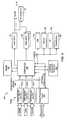
- the diagram shown in FIG. 4describes one embodiment of an STB system 400 that features such a packet processing circuit.
- a Transport Stream Interface (TSI) 404may couple tuners 401 a , 401 b , and 401 c directly to the STB/PVR System On a Chip (SOC) 406 .
- TSI 404may also couple packet processing circuit 402 to STB/PVR SOC 406 .
- TSI 404may be a dedicated bus configured specifically for transferring real-time application data. While FIG. 4 illustrates an embodiment with one TSI, other embodiments may be configured with more than one TSI.
- Packet processor 402may also be coupled to STB/PVR SOC 406 via a local bus 410 representing a memory bus or I/O bus interface/connection, for example.
- Local bus 410may be an out-of-band (OOB) connection used for non-video and non-audio data that is aggregated into network data flow.
- OOBout-of-band
- Embodiments of local bus 410may include, but not be limited to various CPU bus interfaces, PCI, AHB, DDR, SDRAM, and other like busses well known in the art.
- packet processing circuit 402is an Ethernet/IP decoder that implements some functionality normally associated with code running on an embedded processor that may be configured in STB/PVR SOC 406 .
- One example of such functionalityincludes functions performed in relation to the network stack included in the TCP/IP suite of protocols.
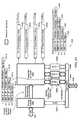
- packet processing circuit 402includes an Ethernet controller 502 , (which may include a 10/100/1000 and 10 Gig physical layer (PHY) and media access controller (MAC)), coupled to a packet filter and router (PFR) 504 for data streaming applications.
- PFR 504may interface with ‘n’ number of receive buffers as represented by receive buffers 508 a - 508 c , which may interface with a host bus 550 via host interface 548 .
- Ethernet controller 502may also interface with host bus 550 via host interface 548 through control signal bus 506 .
- host bus 550coincides with local bus 410 of FIG. 4 .
- host bus 550may support Master and/or Slave DMA.
- the outputs from packet processing circuit 402may be provided by ‘n’ number of TSI buffers represented by TSI buffers 510 a - 510 d , which may be FIFOs. In alternate embodiments, (not shown), outputs from packet processing circuit 402 may be directly provided by PFR 504 to TSI 404 without using TSI buffers 510 a - 510 d .
- TSI buffers 510 a - 510 dmay be physically or logically located outside of, and remote to packet processing circuit 402 , coupling to packet processing circuit 402 , more specifically to PFR 504 , using a standard memory bus architecture such as DDR, DDR2, SDRAM, SRAM or FLASH RAM.
- packet processing circuit 402is configured to support advanced consumer electronics applications, particularly those applications that require the transmission of low jitter, time critical (isochronous) information. Examples of such information include but are not limited to streaming video and audio applications that require transfer of data at a constant bit rate.
- packet processing circuit 402may be configured to support other selected applications that use real-time data.
- packet processing circuit 402is configured to simultaneously filter and route multiple data type streams, thereby transferring specific Ethernet packets to various host interfaces, such as host interface 548 .
- host interfacesinclude standard bus architectures such as PCI, Local Bus or Memory buses, and non-standard busses utilizing variable data bus widths and control definitions.
- Packet processor 402may operate to redirect application data streams to a reception device, for example a video decoder, for data consumption.
- FIG. 11illustrates examples of how video and audio data may be encapsulated into packets for transfer over a network, in this case an Ethernet network, from a content provider to a rendering device. More specifically, encapsulation examples are shown for RTP video/audio content, RTP audio content, and MPEG content.
- PPC 402may be configured to manage an RTP connection through various configuration/control registers and in conjunction with SOC 406 , allowing for reduced jitter and reduced buffering requirements in real-time applications.
- FIG. 12A-BA flow of logical data stream filtering, and application data routing performed by packet processing circuit 402 according to one embodiment is shown in FIG. 12A-B .
- the flow of FIG. 12A-Bis established with the premise that the video or audio server has already established a connection with the receiver, that the connection is established through the host bus interface ( 548 in FIG. 4 ), that the connection is established without any special MAC or transport functionality, and that packet processing circuit 402 comprises a standard network Ethernet controller ( 502 in FIG. 4 ).
- the flow of FIG. 12A-Bmay be adapted to perform logical data stream filtering, and application data routing of data packets conforming to any chosen network standard that is not an Ethernet standard, according to premises associated with that chosen network standard.
- Ethernet connectivity packet processing circuit 402may comprise a 10/100/1000 and 10 Gig Ethernet controller ( 502 in FIG. 5 ) designed for embedded applications where performance and flexibility are required.
- Ethernet controller 502is IEEE 802.3 10BASE-T and 802.3u 100BASE-TX compliant.
- a data packetin this case an Ethernet packet, intended for a central controller (such as STB/PVR 406 in FIG. 4 ) may be intercepted ( 1202 ).
- the packetmay be stored in the Ethernet MAC data buffers that may be comprised in Ethernet controller 502 ( 1204 ).
- the MAC comprised in Ethernet controller 502may perform address filtering using Ethernet header information, such as shown in FIG. 6 .
- table 600illustrates the format of an Ethernet II frame
- table 602illustrates the format of an 802.3 frame. While the formats shown in FIG. 6 exemplify Ethernet and 802.3 packets, in certain embodiments packet processing circuit 402 may be configured to redirect/route packets of data embedded according to other media access formats, which are used in support of other applications, to a host or a system in a similar manner.
- PFR 504may utilize various network, transport and application layer header information to determine the proper routing to any of the receive buffers 508 a - 508 c , or to any of the TSI buffers 510 a - 510 d .
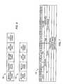
- Examples of the network, transport and application layer headers used in one implementationare shown in FIGS. 7 , 8 and 9 . More specifically, table 700 in FIG. 7 illustrates an example of a network layer protocol IP header, table 800 in FIG. 8 illustrates an example of a transport layer protocol TCP header, table 802 in FIG. 8 illustrates an example of a transport layer protocol UDP header, and table 900 in FIG. 9 illustrates an example of an application layer protocol RTP version 2 header.
- PFR 504may utilize receive buffers 508 a - 508 c to store received Ethernet packets based on a particular port match and according to a specific priority scheme, in which priority scheme SOC 406 may operate to retrieve through Host Interface 548 a particular sequence of packets corresponding to the matched port in a sequence that is different from the sequence in which the particular packets may have been serially received by Controller 502 .
- SOCmay be operated to retrieve data packets stored in receive buffers 508 a - 508 c in a different order relative to the sequence in which the data packets have been originally transmitted via LAN 501 .
- the IP header fields “Fragment offset” and “Flags”may be parsed to determine if the data packet is fragmented ( 1206 ). Fragmentation may be interpreted as the Total Length of the logical IP data packet exceeding the MAC length or Ethernet packet length.
- packet processing circuit 402is configured to support fragmented IP data-grams. To enable such support, storage memory of a size commensurate with the length of the maximum IP frame (up to 65,535 Bytes in one set of embodiments) may be configured internally within packet processing circuit 402 , or externally, interfacing with packet processing circuit 402 through a dedicated bus. In one set of embodiments, the values for the “Fragment offset” and “Flags” fields may be checked to determine whether external memory is required in case the internal memory cannot satisfy the buffer requirements.
- the “Header Checksum” fieldmay be used to verify the data integrity of the data packet as part of IP header validation ( 1208 and 1210 ). While in some embodiments the checksum value is validated, in other embodiments the checksum value may not be validated even though it may be available. Other checksum and/or CRC fields may be made available, as part of the header information shown in table 700 of FIG. 7 , and redundant checks may not be required.
- the Internet Header Length (IHL) fieldmay be checked to verify the length of the associated header as well as to determine the offset of the subsequent headers for further processing.
- the “Destination IP address”may be checked to verify the routing of the packet.
- the transport layer TCP header “Destination Port” informationmay be used to determine if the data packet is targeting a TCP port ( 1218 ) and continue routing the data packet to one of the receive buffers ( 508 a - 508 c in FIG. 5 ) in case of an invalid TCP port ( 1212 ), or to any of the transport stream buffers ( 510 a - 510 d in FIG. 5 ) in case of a valid TCP port ( 1224 ).
- the “Checksum” fieldmay also be evaluated to determine data integrity.
- the Transport Layer UDP header “Destination Port”may be used to determine if the data packet is targeting a UDP port ( 1216 ) and continue routing the data packet to one of the receive buffers ( 508 a - 508 c in FIG. 5 ) in case of an invalid UDP port ( 1212 ), or to any of the transport stream buffers ( 510 a - 510 d in FIG. 5 ) in case of a valid UDP port ( 1224 ).
- the “Checksum” field and “Length” fieldmay also be evaluated to determine data integrity.
- the Application Layer RTP header “PT”(Payload Type) field may be used to determine the payload data type ( 1224 ), and ascertain if it is a valid payload data type for transfer to a TSI buffer ( 1222 ), and continue routing the payload data to one of the receive buffers ( 508 a - 508 c in FIG. 5 ) ( 1212 ) or to any of the transport stream buffers ( 510 a - 510 d in FIG. 5 ) ( 1220 ).
- the “Sequence Number” fieldmay also be evaluated to determine out of order or duplication of packets.
- the “Time Stamp” fieldmay also be evaluated in order for the Host System to facilitate real time data streaming through obtaining feedback on time critical information, including synchronization and jitter calculations.
- multimedia content in conjunction with one of many real time streaming protocolsincluding but not limited to the Real Time Streaming Protocol (RTSP), may make use of the “Time Stamp” field information.
- RTSPReal Time Streaming Protocol
- FIG. 10 and FIG. 11illustrate the placement and ordering of the various headers within the Ethernet packet structure used in one set of embodiments.
- the packet structure shownmay remain unchanged once the data or video stream is configured and started, however the various fields of the individual headers may change based on network traffic and routing options.
- an Ethernet packetmay consist of header(s) and a payload.
- the headersmay vary depending on the application and network type. One or more headers may be required, and the order of the headers may typically be MAC, Network (IP in FIGS. 10 and 11 ), Transport (UDP and TCP), and application layer protocols (RTP in FIGS. 10 and 11 ), and other application headers.
- Packet processor 402may be configured to be flexible in how it routes the data to the appropriate external Host or TSIs.
- TSI( 404 in FIG. 4 ) comprises specific methods, signal definitions, protocols, bus arrangements, and timing, which together constitute a data flow.
- TSI 404is configured to operate in a manner different from a typical host, device and/or memory interface.
- a typical or standard host interfacemay include PCI, VCI, PVCI, AHB, ASB, APB, Cardbus, Local Bus, and other CPU Host bus interfaces, which are defined as Shared System Interfaces (SSI). It may also include DDR, DDR2, SDRAM, SRAM, FLASH RAM, and Synchronous SRAM (SSRAM), which are defined as Memory Interfaces (MI).
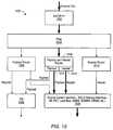
- the diagram in FIG. 13shows the general data flow, routing and filtering structure for packet processing circuit 402 .
- the structurecomprises a filter block 1304 programmable to interpret the header fields as shown in tables 700 , 800 , 802 , and 900 of FIGS. 7 , 8 , and 9 , respectively.
- the structuremay also comprise a payload router 1306 , a payload and header router 1308 , and a header router 1310 . It should be noted that the routers are not limited to the headers defined in FIGS. 7 , 8 , and 9 . Some embodiments may include other IETF header types, including other proprietary and non-standard encapsulation header types.
- any and/or all of individual routers 1306 , 1308 , and 1310may be configured to support a “cut-through” or “store-and-forward” architecture. Differences between the two architectures may affect the design parameters of buffer utilization, buffer size, jitter and system latency tolerance. For example, both architectures may be viable in case streaming content is transmitted at a constant bit rate, and if the content is—in the case of video—adaptive to the frame rate of the rendering device. Should such restrictions not be possible, buffer arrangements may be implemented according to a store-and-forward architecture.
- Payload router 1306may be used to decide whether the payload is routed to TSI 1316 or SSI/MI 1318 .
- FIG. 14illustrates the flow structure for embodiments where only payload router 1406 (representing payload router 1306 from FIG. 13 in FIG. 14 ) is used, in which case the header is discarded. The heavily outlined path in FIG. 14 illustrates the flow for this case.
- MAC/PHY 1402may receive a packet, which may be filtered by filter 1404 , and routed by payload router 1406 to TSI 1416 and/or to SSI/MI 1418 .
- FIG. 21shows a rendition of the embodiment of packet processing circuit 402 according to FIG.
- Ethernet controller 2102may pass the data received over LAN 2101 to packet filter and router 2104 .
- TSI interface buffers 2110 a - 2110 dallow the processing of individual headers and payload for each packet 2111 a - 2111 d .
- the headersmay be discarded and the application data or payload may be routed to the TSI ports.
- TSI buffers or FIFOs 2110 a - 2110 dstore the payload data before it is passed to the TSI output.
- Bufferingmay or may not be required based on the ability of the entire system to establish a constant bit rate equivalent to the framing rate of the data-consuming device at the TSI output.
- the headersshown in the context of Ethernet packets that have a “MAC” or “MAC and IP” or “MAC, IP, UDP and RTP” header and other variations
- the application datamay be passed to the TSI.
- FIG. 15illustrates the flow structure for embodiments where the payload and header router 1508 (representing payload and header router 1308 from FIG. 13 in FIG. 15 ) routes both the payload and header to SSI and/or MI 1518 (representing payload and header router 1318 from FIG. 13 in FIG. 15 ).
- the heavily outlined path in FIG. 15illustrates the flow for this case.
- MAC/PHY 1502may receive a packet, which may be filtered by filter 1564 , and routed by payload and header router 1508 to SSI/MI 1518 .
- payload 1512 and header 1514are routed distinctly to SSI/MI 1518 .
- the packets that match the filter criteriamay comprise packets that are not specific to any particular application type.
- packet processing circuit 402is configured to have all packets routed to host interface 548 and not utilize TSI interface 510 a - 510 d , the flow structure shown in FIG. 15 may be utilized.
- the headerwill not be routed to TSI 1516 , while the payload may be routed to either the TSI 1516 or SSI/MI 1518 .
- FIG. 16illustrates the flow structure for embodiments where the payload is routed to TSI 1616 (representing TSI 1316 from FIG. 13 in FIG. 16 ) while the associated header is routed to SSI/MI 1618 (representing SSI/MI 1318 from FIG. 13 in FIG. 16 ).
- FIG. 22shows a rendition of the embodiment of packet processing circuit 402 according to FIG.
- Ethernet Controller 2202may pass the Ethernet packet that went through MAC layer filtering of either a unique IEEE 802.3 6-byte individual, Multicast or group Multicast address.
- the packetmay be parsed in PFR 2204 for the appropriate header information at one or more of the layers, which may comprise network, transport and/or application layers.
- the application data or data payload(from packets 2211 a - 2211 d ) is stripped and/or routed to one or more of TSI ports 2210 a - 2210 d .
- the corresponding header or headers(also from packets 2211 a - 2211 d ) are passed to host bus 2250 via SSI/MI 2248 using, as depicted in FIG. 22 , buffer 2208 b .
- the buffering as shown in FIG. 22is optional, and cut-through or store-and-forward methodology may be used depending on the overall system architecture trade-offs, previously enumerated.
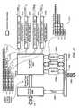
- FIG. 23shows a rendition of the embodiment of packet processing circuit 402 according to FIG. 5 , highlighting the components that are involved in packet transfer when packets that do not match any of the filtered criteria are routed through the same path.
- any of packets 2311 a - 2311 d that are non-matched and non-application specificmay be routed to host interface 2348 via buffer 2308 c.
- FIG. 24shows a rendition of the embodiment of packet processing circuit 402 according to FIG. 5 , highlighting the components that are involved in packet transfer when non-matched packets are placed in buffer 2408 c and matched packets are placed in buffer 2408 b .
- the utilization of multiple buffers or FIFOsmay enable the host system to create priority queues in which specific Ethernet Packets with varying header types, IP, UDP, TCP, or application packet types may be routed to the associated host port. This may allow processing of individual Ethernet packets to be prioritized by the host system.
- the payload that is routed to Host Bus 2350may or may not contain encrypted data.
- FIG. 17illustrates the flow structure for embodiments where the Ethernet data headers are routed to the host interface and the payload data is discarded.
- Header router 1714(representing header router 1314 from FIG. 13 in FIG. 17 ) may be used to route the header or headers of the Ethernet packet—received by MAC/PHY 1702 and filtered by filter 1704 —to SSI/MI 1718 (representing SSI/MI 1318 from FIG. 13 in FIG. 17 ). This may be performed when the payload is not required for a given application.
- the flow structure illustrated in FIG. 17may be used for diagnostic and performance optimization.
- the header informationmay be used for statistical information, and the payload, since it is being discarded, will not incur additional host processing.
- FIG. 18describes the transport stream signal interface according to one embodiment.
- the interface in FIG. 18may be designed to handle data streaming, and represents a non-standard interface. In one set of embodiments, streaming video and audio data may be transferred over this interface.
- the signalscomprise a TS Error output, TS Packet Clock, TS (Octet, nibble or bit) Clock, and TS Data Valid, as well as the Transport Stream Data, which may be in the form of, but not limited to, a serial bit stream, 4-bit (nibble) or 8-bit (Byte) connection.
- the timing and relationship of these signals according to one embodimentis outlined in FIG. 19 .
- transport stream data 1902may be delivered using a serial bit stream, 4-bit (nibble) or 8-bit (Byte) type bus connection.
- “Byte0, Byte1, Byte2, ByteN”may indicate the transport stream data bus width being 8 bits.
- the rising (in this case asserting) edge of TS Packet Clock 1906may indicate the first 8-bit (Byte), 4-bit (Nibble) or bit of the packet or frame.
- a packet in this contextmay not necessarily mean an Ethernet Packet, but the start of a data payload byte at the beginning of, or offset from the start of, an Ethernet data payload.
- TS Packet Clock 1906is a synchronous clock that runs at specific frequencies based on a given application. In case of video applications, for example MPEG2, the clock rate of TS Packet Clock 1906 for serial data may be 27 MHz. At nibble or Byte bus widths, the frequency may be less.
- TS Data Valid signal 1904may be used to determine the start and end of a packet or frame. TS Data Valid 1904 may be asserted on the first byte of the packet or frame and de-asserted on the last byte.
- TS Packet Error signal 1910may be used to flag erroneous data or errors in reception of Transport Stream data 1902 .
- the data comprised in Transport Stream data 1902may be ignored when TS Packet Error signal 1910 is asserted during the falling edge of TS Packet Clock 1906 .
- host interface 548 comprised in packet processing circuit 402may function as a communication bus between packet processing circuit 402 and a Host System (for example STB/PVR SOC 406 in FIG. 4 ) coupled to packet processing circuit 402 .
- a Host Systemfor example STB/PVR SOC 406 in FIG. 4
- standard bus architecturesmay be used to implement host interface 548 . Examples of standard bus architectures that may be used include PCI, VCI, PVCI, AHB, ASB, APB, Cardbus, and Local Bus.
- Memory Bus architecturessuch as DDR, DDR2, SDRAM, SRAM, FLASH RAM, and SSRAM may also be used.
- signals for a standard “Local Bus”are shown in FIG. 20 .
Landscapes
- Engineering & Computer Science (AREA)
- Computer Networks & Wireless Communication (AREA)
- Signal Processing (AREA)
- Computer Security & Cryptography (AREA)
- Multimedia (AREA)
- Data Exchanges In Wide-Area Networks (AREA)
Abstract
Description
Claims (34)
Priority Applications (7)
| Application Number | Priority Date | Filing Date | Title |
|---|---|---|---|
| US11/046,292US8281031B2 (en) | 2005-01-28 | 2005-01-28 | High speed ethernet MAC and PHY apparatus with a filter based ethernet packet router with priority queuing and single or multiple transport stream interfaces |
| PCT/US2006/000126WO2006083467A1 (en) | 2005-01-28 | 2006-01-04 | High speed ethernet mac and phy apparatus with a filter based ethernet packet router with priority queuing and single or multiple transport stream interfaces |
| EP06717346AEP1847073A1 (en) | 2005-01-28 | 2006-01-04 | High speed ethernet mac and phy apparatus with a filter based ethernet packet router with priority queuing and single or multiple transport stream interfaces |
| TW095102844ATW200642360A (en) | 2005-01-28 | 2006-01-25 | High speed ethernet MAC and PHY apparatus with a filter based ethernet packet router with priority queuing and single or multiple transport stream interfaces |
| KR1020060008389AKR100732018B1 (en) | 2005-01-28 | 2006-01-26 | High speed ethernet mac and phy apparatus with a filter based ethernet packet router with priority queuing and single or multiple transport stream interfaces |
| JP2006018622AJP2006211681A (en) | 2005-01-28 | 2006-01-27 | Fast Ethernet MAC and PHY devices with filter-based Ethernet packet router with priority queue and single or multiple transport stream interfaces |
| US13/607,022US8880728B2 (en) | 2005-01-28 | 2012-09-07 | High speed ethernet MAC and PHY apparatus with a filter based ethernet packet router with priority queuing and single or multiple transport stream interfaces |
Applications Claiming Priority (1)
| Application Number | Priority Date | Filing Date | Title |
|---|---|---|---|
| US11/046,292US8281031B2 (en) | 2005-01-28 | 2005-01-28 | High speed ethernet MAC and PHY apparatus with a filter based ethernet packet router with priority queuing and single or multiple transport stream interfaces |
Related Child Applications (1)
| Application Number | Title | Priority Date | Filing Date |
|---|---|---|---|
| US13/607,022DivisionUS8880728B2 (en) | 2005-01-28 | 2012-09-07 | High speed ethernet MAC and PHY apparatus with a filter based ethernet packet router with priority queuing and single or multiple transport stream interfaces |
Publications (2)
| Publication Number | Publication Date |
|---|---|
| US20060174032A1 US20060174032A1 (en) | 2006-08-03 |
| US8281031B2true US8281031B2 (en) | 2012-10-02 |
Family
ID=36177978
Family Applications (2)
| Application Number | Title | Priority Date | Filing Date |
|---|---|---|---|
| US11/046,292Active2030-09-17US8281031B2 (en) | 2005-01-28 | 2005-01-28 | High speed ethernet MAC and PHY apparatus with a filter based ethernet packet router with priority queuing and single or multiple transport stream interfaces |
| US13/607,022Expired - LifetimeUS8880728B2 (en) | 2005-01-28 | 2012-09-07 | High speed ethernet MAC and PHY apparatus with a filter based ethernet packet router with priority queuing and single or multiple transport stream interfaces |
Family Applications After (1)
| Application Number | Title | Priority Date | Filing Date |
|---|---|---|---|
| US13/607,022Expired - LifetimeUS8880728B2 (en) | 2005-01-28 | 2012-09-07 | High speed ethernet MAC and PHY apparatus with a filter based ethernet packet router with priority queuing and single or multiple transport stream interfaces |
Country Status (6)
| Country | Link |
|---|---|
| US (2) | US8281031B2 (en) |
| EP (1) | EP1847073A1 (en) |
| JP (1) | JP2006211681A (en) |
| KR (1) | KR100732018B1 (en) |
| TW (1) | TW200642360A (en) |
| WO (1) | WO2006083467A1 (en) |
Cited By (3)
| Publication number | Priority date | Publication date | Assignee | Title |
|---|---|---|---|---|
| US20130316702A1 (en)* | 2009-03-18 | 2013-11-28 | Broadcom Corporation | Method and System for Timely Delivery of Multimedia Content via a Femtocell |
| US20170055031A1 (en)* | 2015-08-19 | 2017-02-23 | Opentv, Inc. | Method to transmit and receive mpeg-ts over a thunderbolt cable |
| US20180041785A1 (en)* | 2006-11-08 | 2018-02-08 | Microchip Technology Incorporated | Network Traffic Controller (NTC) |
Families Citing this family (48)
| Publication number | Priority date | Publication date | Assignee | Title |
|---|---|---|---|---|
| EP1724983B1 (en)* | 2005-05-17 | 2007-10-10 | Alcatel Lucent | Method of providing a real-time communication connection |
| US7984228B2 (en)* | 2006-02-28 | 2011-07-19 | Microsoft Corporation | Device connection routing for controller |
| US7895635B2 (en)* | 2006-06-30 | 2011-02-22 | Versteeg William C | Systems and methods of assembling an elementary stream from an encapsulated multimedia transport stream |
| US7876768B2 (en)* | 2006-06-30 | 2011-01-25 | Ver Steeg William C | Systems and methods of assembling an elementary stream from an encapsulated multimedia transport stream |
| US8102853B2 (en)* | 2006-08-09 | 2012-01-24 | Samsung Electronics Co., Ltd. | System and method for wireless communication of uncompressed video having fixed size MAC header with an extension |
| US20080064326A1 (en)* | 2006-08-24 | 2008-03-13 | Stephen Joseph Foster | Systems and Methods for Casting Captions Associated With A Media Stream To A User |
| US8547891B2 (en)* | 2006-10-10 | 2013-10-01 | Qualcomm Incorporated | Systems and methods for improving multicasting over a forward link |
| US20080130561A1 (en)* | 2006-12-04 | 2008-06-05 | Samsung Electronics Co., Ltd. | System and method for wireless communication |
| CN101720554A (en)* | 2007-03-15 | 2010-06-02 | 法布里克斯电视有限公司 | Converting video data into video streams |
| US8862748B2 (en)* | 2007-03-30 | 2014-10-14 | St-Ericsson Sa | Method and system for optimizing power consumption and reducing MIPS requirements for wireless communication |
| US8139581B1 (en) | 2007-04-19 | 2012-03-20 | Owl Computing Technologies, Inc. | Concurrent data transfer involving two or more transport layer protocols over a single one-way data link |
| US8391354B2 (en)* | 2007-05-14 | 2013-03-05 | Broadcom Corporation | Method and system for transforming uncompressed video traffic to network-aware ethernet traffic with A/V bridging capabilities and A/V bridging extensions |
| US20090106806A1 (en)* | 2007-10-01 | 2009-04-23 | Lg Electronics Inc. | Broadcast receiver and system information processing method |
| KR100930444B1 (en)* | 2007-11-01 | 2009-12-08 | (주)휴맥스 홀딩스 | Broadcast data processing device and method in IP broadcast receiver |
| US8407367B2 (en)* | 2007-12-26 | 2013-03-26 | Intel Corporation | Unified connector architecture |
| WO2009093473A1 (en)* | 2008-01-25 | 2009-07-30 | Panasonic Corporation | Relay device, terminal, method of controlling priority communication, program, and recording medium |
| US20090328093A1 (en)* | 2008-06-30 | 2009-12-31 | At&T Intellectual Property I, L.P. | Multimedia Content Filtering |
| GB2466947A (en)* | 2009-01-14 | 2010-07-21 | Nine Tiles Networks Ltd | Transceiving a data stream comprising high and low priority data |
| CN101568027B (en)* | 2009-05-22 | 2012-09-05 | 华为技术有限公司 | Method, device and system for forwarding video data |
| US9270542B2 (en)* | 2009-07-31 | 2016-02-23 | Ixia | Apparatus and methods for forwarding data packets captured from a network |
| CN101697500B (en)* | 2009-10-10 | 2012-08-29 | 华为技术有限公司 | Microwave equipment, microwave system and OAM information transmission method |
| WO2011133711A2 (en) | 2010-04-23 | 2011-10-27 | Net Optics, Inc | Integrated network data collection arrangement and methods thereof |
| EP2388706A1 (en) | 2010-05-21 | 2011-11-23 | Thomson Licensing | Method and system for real-time streaming and storage |
| WO2012099426A2 (en)* | 2011-01-19 | 2012-07-26 | 한국전자통신연구원 | Method and apparatus for transmitting media content via a single port or multiple ports |
| US9553912B2 (en)* | 2011-01-19 | 2017-01-24 | Electronics And Telecommunications Research Institute | Method and apparatus for transmitting media content via a single port or multiple ports |
| CN102176760A (en)* | 2011-03-09 | 2011-09-07 | 华为终端有限公司 | Method for implementing digital television technology and wireless fidelity hot spot device |
| KR101706181B1 (en) | 2011-06-29 | 2017-02-13 | 삼성전자주식회사 | Broadcast receiving device and Method for receiving broadcast thereof |
| US8718806B2 (en) | 2011-09-02 | 2014-05-06 | Apple Inc. | Slave mode transmit with zero delay for audio interface |
| JP5811408B2 (en)* | 2012-05-31 | 2015-11-11 | ソニー株式会社 | Signal processing apparatus and signal processing method |
| US10904075B2 (en) | 2012-07-02 | 2021-01-26 | Keysight Technologies Singapore (Sales) Pte. Ltd. | Preconfigured filters, dynamic updates and cloud based configurations in a network access switch |
| US9250954B2 (en)* | 2013-01-17 | 2016-02-02 | Xockets, Inc. | Offload processor modules for connection to system memory, and corresponding methods and systems |
| US9565139B2 (en) | 2013-03-15 | 2017-02-07 | Comcast Cable Communications, Llc | Remote latency adjustment |
| US9288157B2 (en) | 2013-10-15 | 2016-03-15 | National Instruments Corporation | Time-sensitive switch for scheduled data egress |
| US9967150B2 (en) | 2014-04-30 | 2018-05-08 | Keysight Technologies Singapore (Holdings) Pte. Ltd. | Methods and apparatuses for implementing network visibility infrastructure |
| US10142229B2 (en)* | 2015-03-13 | 2018-11-27 | Oracle International Corporation | Concealed datagram-based tunnel for real-time communications |
| US20170041386A1 (en)* | 2015-08-05 | 2017-02-09 | International Business Machines Corporation | Provisioning a target hosting environment |
| CN105550153B (en)* | 2015-12-12 | 2018-04-20 | 中国航空工业集团公司西安航空计算技术研究所 | A kind of 1394 bus multi-channel flow datas are unpacked method parallel |
| KR102492234B1 (en) | 2016-02-16 | 2023-01-27 | 주식회사 쏠리드 | Distributed antenna system, method for processing frame of the same, and method for avoiding congestion of the same |
| US10303636B2 (en) | 2016-02-29 | 2019-05-28 | Nokia Of America Corporation | Routing paging packets in a system-on-a-chip base station architecture |
| US10205610B2 (en)* | 2016-02-29 | 2019-02-12 | Alcatel Lucent | Uplink packet routing in a system-on-a-chip base station architecture |
| US10015719B2 (en) | 2016-02-29 | 2018-07-03 | Alcatel-Lucent | Downlink packet routing in a system-on-a-chip base station architecture |
| CN106953853B (en)* | 2017-03-10 | 2020-12-04 | 桂林电子科技大学 | A kind of network-on-chip Gigabit Ethernet resource node and working method thereof |
| US10560357B2 (en) | 2017-11-28 | 2020-02-11 | Marvell World Trade Ltd. | Distributed checksum calculation for communication packets |
| US10673994B2 (en) | 2018-03-29 | 2020-06-02 | Marvell International Ltd. | Network packet generator employing multiple header templates and configurable hardware registers |
| US10469633B2 (en) | 2018-03-29 | 2019-11-05 | Marvell World Trade Ltd. | Low-latency pipeline for media-to-ethernet frame packaging |
| CN110188132B (en)* | 2019-04-29 | 2023-05-05 | 安徽晶奇网络科技股份有限公司 | A data exchange method and system |
| CN111866602A (en)* | 2020-06-19 | 2020-10-30 | 成都东方盛行电子有限责任公司 | Lossless high-precision stream acquisition method |
| KR102819600B1 (en) | 2024-10-21 | 2025-06-12 | 주식회사 케빅 | A broadband network-based audio streaming broadcasting system that supports time synchronization of audio packets |
Citations (33)
| Publication number | Priority date | Publication date | Assignee | Title |
|---|---|---|---|---|
| US5598581A (en)* | 1993-08-06 | 1997-01-28 | Cisco Sytems, Inc. | Variable latency cut through bridge for forwarding packets in response to user's manual adjustment of variable latency threshold point while the bridge is operating |
| US5948069A (en)* | 1995-07-19 | 1999-09-07 | Hitachi, Ltd. | Networking system and parallel networking method |
| WO1999065196A1 (en) | 1998-06-10 | 1999-12-16 | Merlot Communications, Inc. | Integrated voice and data communications over a local area network |
| US20010004768A1 (en) | 1998-09-28 | 2001-06-21 | Hodge Winston W. Hodge Winston W. | Highly integrated computer controlled digital head end |
| US20010005908A1 (en) | 1998-09-28 | 2001-06-28 | Hodge Winston W. | Method for buffering video, data and voice signals using a common shared bus |
| US20020007494A1 (en) | 1998-09-28 | 2002-01-17 | Hodge Winston W. | Interactive digital program material encoder and system |
| US20020015409A1 (en) | 2000-07-20 | 2002-02-07 | Wei Gao | Broadband Ethernet video data transmission |
| US20020019984A1 (en) | 2000-01-14 | 2002-02-14 | Rakib Selim Shlomo | Headend cherrypicker with digital video recording capability |
| US20020048258A1 (en) | 2000-10-16 | 2002-04-25 | Kazuya Oyama | Network communication method, network communication device and information device |
| US6385647B1 (en) | 1997-08-18 | 2002-05-07 | Mci Communications Corporations | System for selectively routing data via either a network that supports Internet protocol or via satellite transmission network based on size of the data |
| US20020059637A1 (en) | 2000-01-14 | 2002-05-16 | Rakib Selim Shlomo | Home gateway for video and data distribution from various types of headend facilities and including digital video recording functions |
| US20020087976A1 (en) | 2000-12-28 | 2002-07-04 | Kaplan Marc P. | System and method for distributing video with targeted advertising using switched communication networks |
| US20020091003A1 (en) | 2001-01-11 | 2002-07-11 | Beken Robert A. | Multi-player electronic entertainment system |
| US20020095681A1 (en) | 2001-01-16 | 2002-07-18 | Freddie Lin | Uncompressed IP multimedia data transmission and switching |
| US20020143996A1 (en) | 2001-03-29 | 2002-10-03 | Vic Odryna | Passive video multiplexing method and apparatus priority to prior provisional application |
| US20020147982A1 (en) | 1999-07-20 | 2002-10-10 | @Security Broadband Corp | Video security system |
| US6473441B1 (en) | 1998-12-18 | 2002-10-29 | Escient Convergence Corp | Multi-channel video pump |
| US20020161918A1 (en)* | 2001-04-27 | 2002-10-31 | Fujitsu Limited Of Kawasaki, Japan | Packet transmission system in which packet is transferred without replacing address in the packet |
| US20020178274A1 (en)* | 2001-03-06 | 2002-11-28 | Kovacevic Branko D. | System for digital stream transmission and method thereof |
| US20030050989A1 (en) | 2001-09-10 | 2003-03-13 | Digigram | Audio data transmission system between a master module and slave modules by means of a digital communication network |
| US20030058885A1 (en) | 2001-09-18 | 2003-03-27 | Sorenson Donald C. | Multi-carrier frequency-division multiplexing (FDM) architecture for high speed digital service in local networks |
| US20030061621A1 (en) | 2001-09-26 | 2003-03-27 | Micro Technology Services, Inc. | Transportable LAN-based surveillance system |
| US20030081131A1 (en) | 2001-10-26 | 2003-05-01 | Koninklijke Philips Electronics N.V. | Method for viewing and controlling multiple DVR's |
| US20030093563A1 (en) | 2001-10-10 | 2003-05-15 | Young Bruce Fitzgerald | Method and system for implementing and managing a multimedia access network device |
| US20030126294A1 (en) | 2001-11-19 | 2003-07-03 | Thorsteinson Thomas M. | Transmitting digital video signals over an IP network |
| US20030133456A1 (en) | 2002-01-11 | 2003-07-17 | Alcatel | Modem system and aggregator for paths with different transmission profiles |
| WO2003063425A1 (en) | 2002-01-18 | 2003-07-31 | Telefonaktiebolaget Lm Ericsson (Publ.) | Adaptive ethernet switch system and method |
| US6611531B1 (en) | 1998-09-30 | 2003-08-26 | Cisco Technology, Inc. | Method and apparatus for routing integrated data, voice, and video traffic |
| US20030163826A1 (en) | 2002-02-25 | 2003-08-28 | Sentrus, Inc. | Method and system for remote wireless video surveillance |
| US20030169314A1 (en) | 2002-03-05 | 2003-09-11 | Mcalonis Matthew R. | Connector assembly for printer ink cartridge |
| US6678740B1 (en) | 2000-01-14 | 2004-01-13 | Terayon Communication Systems, Inc. | Process carried out by a gateway in a home network to receive video-on-demand and other requested programs and services |
| US7050440B2 (en) | 2000-11-24 | 2006-05-23 | International Business Machines Corporation | Method and structure for variable-length frame support in a shared memory switch |
| US7680943B2 (en)* | 2003-10-20 | 2010-03-16 | Transwitch Corporation | Methods and apparatus for implementing multiple types of network tunneling in a uniform manner |
Family Cites Families (7)
| Publication number | Priority date | Publication date | Assignee | Title |
|---|---|---|---|---|
| KR100363886B1 (en)* | 1999-12-27 | 2002-12-11 | 한국전자통신연구원 | Interface method of network processing module in multilayer packet switch system and multilayer packet switch system |
| KR100462474B1 (en)* | 2002-11-29 | 2004-12-17 | 한국전자통신연구원 | Message exchange device and method for IPC(inter processor communication) using the packet ring |
| US20040165586A1 (en) | 2003-02-24 | 2004-08-26 | Read Christopher Jensen | PID filters based network routing |
| JP2004336437A (en) | 2003-05-08 | 2004-11-25 | Matsushita Electric Ind Co Ltd | Video receiving circuit and video receiving device |
| KR20050032764A (en)* | 2003-10-02 | 2005-04-08 | 엘지전자 주식회사 | Packet routing method in communication network based point-to-point protocol over ethernet protocol |
| KR100570815B1 (en)* | 2004-01-07 | 2006-04-12 | 삼성전자주식회사 | Distributed Ethernet Switching System and Packet Transmission Method Using the Same |
| JP4470585B2 (en) | 2004-05-26 | 2010-06-02 | パナソニック株式会社 | Network interface and packet transmitting / receiving device |
- 2005
- 2005-01-28USUS11/046,292patent/US8281031B2/enactiveActive
- 2006
- 2006-01-04EPEP06717346Apatent/EP1847073A1/ennot_activeWithdrawn
- 2006-01-04WOPCT/US2006/000126patent/WO2006083467A1/enactiveApplication Filing
- 2006-01-25TWTW095102844Apatent/TW200642360A/enunknown
- 2006-01-26KRKR1020060008389Apatent/KR100732018B1/ennot_activeExpired - Fee Related
- 2006-01-27JPJP2006018622Apatent/JP2006211681A/enactivePending
- 2012
- 2012-09-07USUS13/607,022patent/US8880728B2/ennot_activeExpired - Lifetime
Patent Citations (34)
| Publication number | Priority date | Publication date | Assignee | Title |
|---|---|---|---|---|
| US5598581A (en)* | 1993-08-06 | 1997-01-28 | Cisco Sytems, Inc. | Variable latency cut through bridge for forwarding packets in response to user's manual adjustment of variable latency threshold point while the bridge is operating |
| US5948069A (en)* | 1995-07-19 | 1999-09-07 | Hitachi, Ltd. | Networking system and parallel networking method |
| US6385647B1 (en) | 1997-08-18 | 2002-05-07 | Mci Communications Corporations | System for selectively routing data via either a network that supports Internet protocol or via satellite transmission network based on size of the data |
| WO1999065196A1 (en) | 1998-06-10 | 1999-12-16 | Merlot Communications, Inc. | Integrated voice and data communications over a local area network |
| US20010004768A1 (en) | 1998-09-28 | 2001-06-21 | Hodge Winston W. Hodge Winston W. | Highly integrated computer controlled digital head end |
| US20020007494A1 (en) | 1998-09-28 | 2002-01-17 | Hodge Winston W. | Interactive digital program material encoder and system |
| US20010005908A1 (en) | 1998-09-28 | 2001-06-28 | Hodge Winston W. | Method for buffering video, data and voice signals using a common shared bus |
| US6611531B1 (en) | 1998-09-30 | 2003-08-26 | Cisco Technology, Inc. | Method and apparatus for routing integrated data, voice, and video traffic |
| US6473441B1 (en) | 1998-12-18 | 2002-10-29 | Escient Convergence Corp | Multi-channel video pump |
| US20020147982A1 (en) | 1999-07-20 | 2002-10-10 | @Security Broadband Corp | Video security system |
| US20020019984A1 (en) | 2000-01-14 | 2002-02-14 | Rakib Selim Shlomo | Headend cherrypicker with digital video recording capability |
| US20020059637A1 (en) | 2000-01-14 | 2002-05-16 | Rakib Selim Shlomo | Home gateway for video and data distribution from various types of headend facilities and including digital video recording functions |
| US20040172658A1 (en) | 2000-01-14 | 2004-09-02 | Selim Shlomo Rakib | Home network for ordering and delivery of video on demand, telephone and other digital services |
| US6678740B1 (en) | 2000-01-14 | 2004-01-13 | Terayon Communication Systems, Inc. | Process carried out by a gateway in a home network to receive video-on-demand and other requested programs and services |
| US20020015409A1 (en) | 2000-07-20 | 2002-02-07 | Wei Gao | Broadband Ethernet video data transmission |
| US20020048258A1 (en) | 2000-10-16 | 2002-04-25 | Kazuya Oyama | Network communication method, network communication device and information device |
| US7050440B2 (en) | 2000-11-24 | 2006-05-23 | International Business Machines Corporation | Method and structure for variable-length frame support in a shared memory switch |
| US20020087976A1 (en) | 2000-12-28 | 2002-07-04 | Kaplan Marc P. | System and method for distributing video with targeted advertising using switched communication networks |
| US20020091003A1 (en) | 2001-01-11 | 2002-07-11 | Beken Robert A. | Multi-player electronic entertainment system |
| US20020095681A1 (en) | 2001-01-16 | 2002-07-18 | Freddie Lin | Uncompressed IP multimedia data transmission and switching |
| US20020178274A1 (en)* | 2001-03-06 | 2002-11-28 | Kovacevic Branko D. | System for digital stream transmission and method thereof |
| US20020143996A1 (en) | 2001-03-29 | 2002-10-03 | Vic Odryna | Passive video multiplexing method and apparatus priority to prior provisional application |
| US20020161918A1 (en)* | 2001-04-27 | 2002-10-31 | Fujitsu Limited Of Kawasaki, Japan | Packet transmission system in which packet is transferred without replacing address in the packet |
| US20030050989A1 (en) | 2001-09-10 | 2003-03-13 | Digigram | Audio data transmission system between a master module and slave modules by means of a digital communication network |
| US20030058885A1 (en) | 2001-09-18 | 2003-03-27 | Sorenson Donald C. | Multi-carrier frequency-division multiplexing (FDM) architecture for high speed digital service in local networks |
| US20030061621A1 (en) | 2001-09-26 | 2003-03-27 | Micro Technology Services, Inc. | Transportable LAN-based surveillance system |
| US20030093563A1 (en) | 2001-10-10 | 2003-05-15 | Young Bruce Fitzgerald | Method and system for implementing and managing a multimedia access network device |
| US20030081131A1 (en) | 2001-10-26 | 2003-05-01 | Koninklijke Philips Electronics N.V. | Method for viewing and controlling multiple DVR's |
| US20030126294A1 (en) | 2001-11-19 | 2003-07-03 | Thorsteinson Thomas M. | Transmitting digital video signals over an IP network |
| US20030133456A1 (en) | 2002-01-11 | 2003-07-17 | Alcatel | Modem system and aggregator for paths with different transmission profiles |
| WO2003063425A1 (en) | 2002-01-18 | 2003-07-31 | Telefonaktiebolaget Lm Ericsson (Publ.) | Adaptive ethernet switch system and method |
| US20030163826A1 (en) | 2002-02-25 | 2003-08-28 | Sentrus, Inc. | Method and system for remote wireless video surveillance |
| US20030169314A1 (en) | 2002-03-05 | 2003-09-11 | Mcalonis Matthew R. | Connector assembly for printer ink cartridge |
| US7680943B2 (en)* | 2003-10-20 | 2010-03-16 | Transwitch Corporation | Methods and apparatus for implementing multiple types of network tunneling in a uniform manner |
Non-Patent Citations (7)
| Title |
|---|
| International search report and written opinion for application No. PCT/US2006/000126 mailed Sep. 19, 2006. |
| Japanese Office Action for application No. 2006-18622, mailed Jul. 25, 2008, 5 pages. |
| Patent Abstracts of Japan; Publication No. 2004-336437, filed May 8, 2003 by Matsushita Electric Ind. Co. Ltd.; for corresponding Japanese Application No. 2003-130115 published Nov. 25, 2004. |
| Patent Abstracts of Japan; Publication No. 2005-341107, filed May 26, 2004 by Matsushita Electric Ind. Co. Ltd.; for corresponding Japanese Application No. 2004-155827 published Dec. 8, 2005. |
| Taifatech, Inc., "TF-530 Digital TV Steaming Controller," Product Brief, Oct. 27, 2004, http://www.taifatech.com.tw/. |
| Taiwanese Patent Application TW 513635, published Dec. 11, 2002 (abstract only). |
| Taiwanese Patent Office Search Report for application No. 095102844, search completed May 26, 2008. |
Cited By (4)
| Publication number | Priority date | Publication date | Assignee | Title |
|---|---|---|---|---|
| US20180041785A1 (en)* | 2006-11-08 | 2018-02-08 | Microchip Technology Incorporated | Network Traffic Controller (NTC) |
| US10749994B2 (en)* | 2006-11-08 | 2020-08-18 | Standard Microsystems Corporation | Network traffic controller (NTC) |
| US20130316702A1 (en)* | 2009-03-18 | 2013-11-28 | Broadcom Corporation | Method and System for Timely Delivery of Multimedia Content via a Femtocell |
| US20170055031A1 (en)* | 2015-08-19 | 2017-02-23 | Opentv, Inc. | Method to transmit and receive mpeg-ts over a thunderbolt cable |
Also Published As
| Publication number | Publication date |
|---|---|
| JP2006211681A (en) | 2006-08-10 |
| US20060174032A1 (en) | 2006-08-03 |
| US20130010795A1 (en) | 2013-01-10 |
| EP1847073A1 (en) | 2007-10-24 |
| WO2006083467A1 (en) | 2006-08-10 |
| KR20060087434A (en) | 2006-08-02 |
| US8880728B2 (en) | 2014-11-04 |
| TW200642360A (en) | 2006-12-01 |
| KR100732018B1 (en) | 2007-06-25 |
Similar Documents
| Publication | Publication Date | Title |
|---|---|---|
| US8281031B2 (en) | High speed ethernet MAC and PHY apparatus with a filter based ethernet packet router with priority queuing and single or multiple transport stream interfaces | |
| US10749994B2 (en) | Network traffic controller (NTC) | |
| US7817642B2 (en) | MoCA frame bundling and frame bursting | |
| CN101027862B (en) | Multi-channel communication with hierarchical communication traffic | |
| US9800909B2 (en) | Method and apparatus for downloading content using channel bonding | |
| KR101080541B1 (en) | Universal network interface for home networks | |
| US20090022154A1 (en) | Reception device, reception method, and computer-readable medium | |
| US20150215669A1 (en) | Premises gateway apparatus and methods for use in a content-based network | |
| CN1781284A (en) | Network routing based on PID filter | |
| US20080095155A1 (en) | Programmable communications system | |
| US20040194147A1 (en) | Broadband multi-interface media module | |
| CN101557513A (en) | DVB router-sharing method and DVB router-sharing device | |
| US20040125754A1 (en) | Method and apparatus for integrating non-IP and IP traffic on a home network | |
| US20060215648A1 (en) | System and method for hardware based protocol conversion between audio-visual stream and ip network | |
| US20070033628A1 (en) | Ethernet port control method and apparatus of digital broadcasting system | |
| US7724647B2 (en) | Method and system for fast channel change in a DOCSIS set top gateway device | |
| US20090158376A1 (en) | Method and apparatus of building ip-based video service system in hybrid fiber coax network | |
| KR100609144B1 (en) | Apparatus for traffic filtering in the home network system and traffic control system using it | |
| WO2009057953A2 (en) | Apparatus and method for processing broadcasting data in ip broadcasting receiver | |
| AU2021239382A1 (en) | Efficient remote PHY dataplane management for a cable system | |
| WO2001080491A2 (en) | Assembling transport packets into ip packets using a clock signal from the transport stream |
Legal Events
| Date | Code | Title | Description |
|---|---|---|---|
| AS | Assignment | Owner name:STANDARD MICROSYSTEMS CORPORATION, NEW YORK Free format text:ASSIGNMENT OF ASSIGNORS INTEREST;ASSIGNORS:WINCHESTER, NEIL;BRANT, PAUL;CHIECHI, WILLIAM;AND OTHERS;REEL/FRAME:016246/0093 Effective date:20050127 | |
| STCF | Information on status: patent grant | Free format text:PATENTED CASE | |
| FPAY | Fee payment | Year of fee payment:4 | |
| AS | Assignment | Owner name:MICROCHIP TECHNOLOGY INCORPORATED, ARIZONA Free format text:MERGER;ASSIGNOR:STANDARD MICROSYSTEMS CORPORATION;REEL/FRAME:044824/0608 Effective date:20120501 | |
| MAFP | Maintenance fee payment | Free format text:PAYMENT OF MAINTENANCE FEE, 8TH YEAR, LARGE ENTITY (ORIGINAL EVENT CODE: M1552); ENTITY STATUS OF PATENT OWNER: LARGE ENTITY Year of fee payment:8 | |
| AS | Assignment | Owner name:JPMORGAN CHASE BANK, N.A., AS ADMINISTRATIVE AGENT, DELAWARE Free format text:SECURITY INTEREST;ASSIGNORS:MICROCHIP TECHNOLOGY INC.;SILICON STORAGE TECHNOLOGY, INC.;ATMEL CORPORATION;AND OTHERS;REEL/FRAME:053311/0305 Effective date:20200327 | |
| AS | Assignment | Owner name:MICROSEMI CORPORATION, CALIFORNIA Free format text:RELEASE BY SECURED PARTY;ASSIGNOR:JPMORGAN CHASE BANK, N.A, AS ADMINISTRATIVE AGENT;REEL/FRAME:053466/0011 Effective date:20200529 Owner name:MICROSEMI STORAGE SOLUTIONS, INC., ARIZONA Free format text:RELEASE BY SECURED PARTY;ASSIGNOR:JPMORGAN CHASE BANK, N.A, AS ADMINISTRATIVE AGENT;REEL/FRAME:053466/0011 Effective date:20200529 Owner name:ATMEL CORPORATION, ARIZONA Free format text:RELEASE BY SECURED PARTY;ASSIGNOR:JPMORGAN CHASE BANK, N.A, AS ADMINISTRATIVE AGENT;REEL/FRAME:053466/0011 Effective date:20200529 Owner name:MICROCHIP TECHNOLOGY INC., ARIZONA Free format text:RELEASE BY SECURED PARTY;ASSIGNOR:JPMORGAN CHASE BANK, N.A, AS ADMINISTRATIVE AGENT;REEL/FRAME:053466/0011 Effective date:20200529 Owner name:SILICON STORAGE TECHNOLOGY, INC., ARIZONA Free format text:RELEASE BY SECURED PARTY;ASSIGNOR:JPMORGAN CHASE BANK, N.A, AS ADMINISTRATIVE AGENT;REEL/FRAME:053466/0011 Effective date:20200529 | |
| AS | Assignment | Owner name:WELLS FARGO BANK, NATIONAL ASSOCIATION, MINNESOTA Free format text:SECURITY INTEREST;ASSIGNORS:MICROCHIP TECHNOLOGY INC.;SILICON STORAGE TECHNOLOGY, INC.;ATMEL CORPORATION;AND OTHERS;REEL/FRAME:053468/0705 Effective date:20200529 | |
| AS | Assignment | Owner name:WELLS FARGO BANK, NATIONAL ASSOCIATION, AS COLLATERAL AGENT, MINNESOTA Free format text:SECURITY INTEREST;ASSIGNORS:MICROCHIP TECHNOLOGY INCORPORATED;SILICON STORAGE TECHNOLOGY, INC.;ATMEL CORPORATION;AND OTHERS;REEL/FRAME:055671/0612 Effective date:20201217 | |
| AS | Assignment | Owner name:WELLS FARGO BANK, NATIONAL ASSOCIATION, AS NOTES COLLATERAL AGENT, MINNESOTA Free format text:SECURITY INTEREST;ASSIGNORS:MICROCHIP TECHNOLOGY INCORPORATED;SILICON STORAGE TECHNOLOGY, INC.;ATMEL CORPORATION;AND OTHERS;REEL/FRAME:057935/0474 Effective date:20210528 | |
| AS | Assignment | Owner name:MICROSEMI STORAGE SOLUTIONS, INC., ARIZONA Free format text:RELEASE BY SECURED PARTY;ASSIGNOR:WELLS FARGO BANK, NATIONAL ASSOCIATION, AS NOTES COLLATERAL AGENT;REEL/FRAME:059863/0400 Effective date:20220228 Owner name:MICROSEMI CORPORATION, ARIZONA Free format text:RELEASE BY SECURED PARTY;ASSIGNOR:WELLS FARGO BANK, NATIONAL ASSOCIATION, AS NOTES COLLATERAL AGENT;REEL/FRAME:059863/0400 Effective date:20220228 Owner name:ATMEL CORPORATION, ARIZONA Free format text:RELEASE BY SECURED PARTY;ASSIGNOR:WELLS FARGO BANK, NATIONAL ASSOCIATION, AS NOTES COLLATERAL AGENT;REEL/FRAME:059863/0400 Effective date:20220228 Owner name:SILICON STORAGE TECHNOLOGY, INC., ARIZONA Free format text:RELEASE BY SECURED PARTY;ASSIGNOR:WELLS FARGO BANK, NATIONAL ASSOCIATION, AS NOTES COLLATERAL AGENT;REEL/FRAME:059863/0400 Effective date:20220228 Owner name:MICROCHIP TECHNOLOGY INCORPORATED, ARIZONA Free format text:RELEASE BY SECURED PARTY;ASSIGNOR:WELLS FARGO BANK, NATIONAL ASSOCIATION, AS NOTES COLLATERAL AGENT;REEL/FRAME:059863/0400 Effective date:20220228 | |
| AS | Assignment | Owner name:MICROSEMI STORAGE SOLUTIONS, INC., ARIZONA Free format text:RELEASE BY SECURED PARTY;ASSIGNOR:WELLS FARGO BANK, NATIONAL ASSOCIATION, AS NOTES COLLATERAL AGENT;REEL/FRAME:059363/0001 Effective date:20220228 Owner name:MICROSEMI CORPORATION, ARIZONA Free format text:RELEASE BY SECURED PARTY;ASSIGNOR:WELLS FARGO BANK, NATIONAL ASSOCIATION, AS NOTES COLLATERAL AGENT;REEL/FRAME:059363/0001 Effective date:20220228 Owner name:ATMEL CORPORATION, ARIZONA Free format text:RELEASE BY SECURED PARTY;ASSIGNOR:WELLS FARGO BANK, NATIONAL ASSOCIATION, AS NOTES COLLATERAL AGENT;REEL/FRAME:059363/0001 Effective date:20220228 Owner name:SILICON STORAGE TECHNOLOGY, INC., ARIZONA Free format text:RELEASE BY SECURED PARTY;ASSIGNOR:WELLS FARGO BANK, NATIONAL ASSOCIATION, AS NOTES COLLATERAL AGENT;REEL/FRAME:059363/0001 Effective date:20220228 Owner name:MICROCHIP TECHNOLOGY INCORPORATED, ARIZONA Free format text:RELEASE BY SECURED PARTY;ASSIGNOR:WELLS FARGO BANK, NATIONAL ASSOCIATION, AS NOTES COLLATERAL AGENT;REEL/FRAME:059363/0001 Effective date:20220228 | |
| AS | Assignment | Owner name:MICROSEMI STORAGE SOLUTIONS, INC., ARIZONA Free format text:RELEASE BY SECURED PARTY;ASSIGNOR:WELLS FARGO BANK, NATIONAL ASSOCIATION, AS NOTES COLLATERAL AGENT;REEL/FRAME:060894/0437 Effective date:20220228 Owner name:MICROSEMI CORPORATION, ARIZONA Free format text:RELEASE BY SECURED PARTY;ASSIGNOR:WELLS FARGO BANK, NATIONAL ASSOCIATION, AS NOTES COLLATERAL AGENT;REEL/FRAME:060894/0437 Effective date:20220228 Owner name:ATMEL CORPORATION, ARIZONA Free format text:RELEASE BY SECURED PARTY;ASSIGNOR:WELLS FARGO BANK, NATIONAL ASSOCIATION, AS NOTES COLLATERAL AGENT;REEL/FRAME:060894/0437 Effective date:20220228 Owner name:SILICON STORAGE TECHNOLOGY, INC., ARIZONA Free format text:RELEASE BY SECURED PARTY;ASSIGNOR:WELLS FARGO BANK, NATIONAL ASSOCIATION, AS NOTES COLLATERAL AGENT;REEL/FRAME:060894/0437 Effective date:20220228 Owner name:MICROCHIP TECHNOLOGY INCORPORATED, ARIZONA Free format text:RELEASE BY SECURED PARTY;ASSIGNOR:WELLS FARGO BANK, NATIONAL ASSOCIATION, AS NOTES COLLATERAL AGENT;REEL/FRAME:060894/0437 Effective date:20220228 | |
| MAFP | Maintenance fee payment | Free format text:PAYMENT OF MAINTENANCE FEE, 12TH YEAR, LARGE ENTITY (ORIGINAL EVENT CODE: M1553); ENTITY STATUS OF PATENT OWNER: LARGE ENTITY Year of fee payment:12 |