US8280049B2 - Method and apparatus for synthesizing copy protection for reducing/defeating the effectiveness or capability of a circumvention device - Google Patents
Method and apparatus for synthesizing copy protection for reducing/defeating the effectiveness or capability of a circumvention deviceDownload PDFInfo
- Publication number
- US8280049B2 US8280049B2US12/322,004US32200409AUS8280049B2US 8280049 B2US8280049 B2US 8280049B2US 32200409 AUS32200409 AUS 32200409AUS 8280049 B2US8280049 B2US 8280049B2
- Authority
- US
- United States
- Prior art keywords
- video
- signal
- copy protection
- pulses
- sync
- Prior art date
- Legal status (The legal status is an assumption and is not a legal conclusion. Google has not performed a legal analysis and makes no representation as to the accuracy of the status listed.)
- Expired - Fee Related, expires
Links
Images


Classifications
- H—ELECTRICITY
- H04—ELECTRIC COMMUNICATION TECHNIQUE
- H04N—PICTORIAL COMMUNICATION, e.g. TELEVISION
- H04N7/00—Television systems
- H04N7/16—Analogue secrecy systems; Analogue subscription systems
- H04N7/167—Systems rendering the television signal unintelligible and subsequently intelligible
- H04N7/1675—Providing digital key or authorisation information for generation or regeneration of the scrambling sequence
- H—ELECTRICITY
- H04—ELECTRIC COMMUNICATION TECHNIQUE
- H04N—PICTORIAL COMMUNICATION, e.g. TELEVISION
- H04N21/00—Selective content distribution, e.g. interactive television or video on demand [VOD]
- H04N21/40—Client devices specifically adapted for the reception of or interaction with content, e.g. set-top-box [STB]; Operations thereof
- H04N21/43—Processing of content or additional data, e.g. demultiplexing additional data from a digital video stream; Elementary client operations, e.g. monitoring of home network or synchronising decoder's clock; Client middleware
- H04N21/433—Content storage operation, e.g. storage operation in response to a pause request, caching operations
- H04N21/4334—Recording operations
- H—ELECTRICITY
- H04—ELECTRIC COMMUNICATION TECHNIQUE
- H04N—PICTORIAL COMMUNICATION, e.g. TELEVISION
- H04N21/00—Selective content distribution, e.g. interactive television or video on demand [VOD]
- H04N21/80—Generation or processing of content or additional data by content creator independently of the distribution process; Content per se
- H04N21/83—Generation or processing of protective or descriptive data associated with content; Content structuring
- H04N21/835—Generation of protective data, e.g. certificates
- H04N21/8355—Generation of protective data, e.g. certificates involving usage data, e.g. number of copies or viewings allowed
- H—ELECTRICITY
- H04—ELECTRIC COMMUNICATION TECHNIQUE
- H04N—PICTORIAL COMMUNICATION, e.g. TELEVISION
- H04N5/00—Details of television systems
- H04N5/76—Television signal recording
- H04N5/91—Television signal processing therefor
- H04N5/913—Television signal processing therefor for scrambling ; for copy protection
- H04N2005/91307—Television signal processing therefor for scrambling ; for copy protection by adding a copy protection signal to the video signal
- H04N2005/91314—Television signal processing therefor for scrambling ; for copy protection by adding a copy protection signal to the video signal the copy protection signal being a pulse signal inserted in blanking intervals of the video signal, e.g. pseudo-AGC pulses, pseudo-sync pulses
- H—ELECTRICITY
- H04—ELECTRIC COMMUNICATION TECHNIQUE
- H04N—PICTORIAL COMMUNICATION, e.g. TELEVISION
- H04N5/00—Details of television systems
- H04N5/76—Television signal recording
- H04N5/91—Television signal processing therefor
- H04N5/913—Television signal processing therefor for scrambling ; for copy protection
- H04N2005/91357—Television signal processing therefor for scrambling ; for copy protection by modifying the video signal
- H04N2005/91371—Television signal processing therefor for scrambling ; for copy protection by modifying the video signal the video color burst signal being modified
Definitions
- the present inventionrelates to television anti-copy protection processes which hamper or inhibit recording as, for example, on a video cassette recorder (VCR) or personal video recorder (PVR).
- VCRvideo cassette recorder
- PVRpersonal video recorder
- negative going pulsesare paired with positive going pulses.
- pseudo sync and automatic gain control (AGC) pulses and or sync pulses and AGC pulsesconstitute signals that cause a reaction in AGC systems in a VCR, or are detected by a reading system in a compliant device such as a PVR, digital recorder, analog to digital convertor.
- AGCautomatic gain control
- a video anti-copy protection processe.g., copy protected video signal or a video signal including one or more copy protection signal such as pseudo sync/AGC pulses
- a video anti-copy protection processis playable on a television (TV) display while generally causing darkening, color distortion, tearing, loss in at least a portion of a program video signal, or video gain effects in a recorded copy.
- black box deviceswhich remove or attenuate the effects of the anti-copy protection pulses, while passing through the (active field) program video intact.
- black boxesgenerally replace the negative (e.g., pseudo sync) and or positive going pulses (e.g. AGC pulses/signals) with a blanking level or newly regenerated sync pulses free of pseudo sync/AGC signals.
- a copy protection process disclosed in U.S. Pat. No. 4,631,603, John O. Ryan, December 1986, assigned to Macrovision Corporation, Santa Clara, Calif., incorporated by reference,is well known to have placed pseudo sync and AGC pulses in specific television (TV) lines for pre-recorded video home systems (VHS) tape and digital video disc (DVD) playback devices.
- VHSvideo home systems
- DVDdigital video disc
- pseudo sync/AGC pulses inserted in a program video signalprohibit recording by affecting the AGC system of a recorder, while allowing (substantially) normal display of the program video signal.
- the makers of the circumvention deviceshave observed the locations of the added pulses in the vertical blanking interval (VB1), and accordingly have generated a timing pulse to blank out or to modify at least some of the copy protection signals.
- VB1vertical blanking interval
- the anti-copy protection signalsare usually hidden in a portion of the vertical blanking interval, which generally cause a small scanning error in the display device. But because most displays overscan the video information, which results in a cropped picture, the scanning error is generally not noticeable. However, with some displays with less overscan, a small but perceivable geometric distortion may be observed when certain anti-copy protection signals are applied in the vertical blanking interval.
- an anti-copy protection signal or video copy protected signalis playable on a TV display, while prohibiting recording (e.g., prohibiting recording via causing an erroneous signal level by affecting an AGC system in a recorder, which causes darkening, changes in contrast and or brightness levels).
- a copy protected video signalis displayed normally (e.g., with few or negligible or zero artifacts).
- a video copy protection signal(or anti-copy protection signal) is provided, added, and or inserted to a video signal to produce/provide a copy protected video signal.
- a video copy protection signalwhich in effect thwarts one or more intended functions of a circumvention device.
- One effectis to cause a circumvention device to allow the passage therethrough of a number of copy protection pulses or signals such that a VCR still reacts to the copy protection signals following the circumvention device.
- Another effectis to design a copy protection signal such that when it is supplied to a circumvention device, the output of the circumvention device still provides a detectable signal to a compliant video recorder or compliant device.
- Yet another effect of an embodiment of the inventionis to synthesize a copy protection signal such that when coupled to a circumvention device, the output of the circumvention device causes playability problems in a display (or increased copy protection effect(s)) such as blanking out a portion of the viewable area and or causing chroma artifacts.
- the above mentioned effectscan be implemented in a number of ways such as by moving, adding, or shifting anti-copy protection signals toward the vertical sync signal (e.g., in 525 and or 625 line TV standards).
- the effectscan be implemented by synthesizing an anti-copy protection signal such that there is no more than one video line free of negative going pulse(s) between one horizontal blanking interval to a next horizontal blanking interval (e.g., one or more pseudo sync pulse is provided between lines).
- an embodimentprovides a copy protection process comprised of Format A and Format B, wherein the formats are interleaved from one TV line to another. Because the formats have in general different positions of pseudo sync pulses or different numbers or pseudo sync pulses for each format, a TV scanning system's phase lock loop system can be excited into causing errors in scanning. By shifting the pseudo sync pulses of the Format A and Format B copy protection signals closer to the vertical sync signal area or away from the active field, the phase lock loop system is allowed to settle in such a way that playability is improved or that a scanning error is reduced. Alternatively, the playability is improved when Format A equals Format B, when the copy protection signals are shifted away from the active field, or when the copy protection signals are moved closer to the vertical sync signal in the vertical blanking interval (VBI).
- VBIvertical blanking interval
- one embodiment of the inventionprovides an improved playability copy protection signal, wherein the copy protection signal includes pseudo sync signals and provides in TV lines the pseudo sync signals located away from the active video field or closer to the vertical sync signal, wherein the (newly located or provided) pseudo sync signals provide less scanning errors or geometric distortion on a TV set.
- the pseudo sync signalsmay have (same or) different number of pseudo sync pulses from one TV line to another or (same or) different pseudo sync pulse width from one TV line to another line.
- Another embodiment of the inventionincludes providing an improved playability of a copy protection signal, wherein the copy protection signal includes pseudo sync pulses (or pulse pair signals of pseudo sync and AGC signals) of a different number of pseudo sync pulses (or pseudo sync and AGC signals) from one TV line to another line and or different pseudo sync (or pseudo sync and AGC) pulse widths from one TV line to another.
- This embodimentincludes modifying or providing at least one TV line to provide at least two lines consecutively with substantially the same number of pseudo sync pulses and or substantially the same pseudo sync pulse width. It should be noted that the resulting copy protection signal may still include an alternating pattern or format of a number of pseudo sync pulses and or pseudo sync pulse widths from one line to another.
- an embodiment of the inventionmay have (in a 625 line standard such as, for example, PAL or Secam) a Format A, which has 7 (or 6 or at least 1) pseudo sync or AGC pulses on video line 7 (or 6 ), followed by Format B, which has 6 (or 7 or at least 1) pseudo sync or AGC pulses on video line 8 (or 7 ).
- This example embodimentprovides resistance to the intended function of a circumvention device by, for example, causing the black box to blank color burst in a portion of the active field, causing the circumvention device (black box) to remove or modify program video in an active portion of the TV field, and or causing the circumvention device to allow the passage of at least some or all of copy protection signals in a TV field.
- This embodimentalso may provide improved playability of the program video signal.
- a 525 line standarde.g., NTSC or PAL-M
- another embodiment of the inventionprovides one or more (e.g., 4) pseudo sync pulses or pseudo sync and AGC pulses (e.g., starting) at line(s) 10 , 11 , 272 , and or 273 .
- resistance to a circumvention deviceis provided.
- the circumvention devicepasses some or all of the copy protection signals to provide a copy protection or content control effect, whereas the circumvention devices intended function is to remove the copy protection signal to defeat a copy protection or content control effect.
- the 525 or 625 line standard embodiments of previous exampleprovide improved playability for the copy protection process (or for a content control signal), for example, in terms of reduced geometric distortion on a display.
- FIGS. 1A and 1Bare waveforms illustrating examples of prior art copy protection signals.
- FIG. 1Care waveforms of video line locations for a 525 line TV standard such as NTSC.
- FIGS. 2A and 2Bare waveforms illustrating examples of one or more embodiments of the invention.
- FIG. 3Ais a block diagram illustrating a prior art circumvention (“black box”) device.
- FIG. 3Bis a block diagram illustrating a timing circuit including a microprocessor device for a circumvention device.
- FIG. 3Cis a block diagram illustrating a timing circuit including a retriggerable circuit for a circumvention device.
- FIG. 4Aillustrates the line locations of two prior art copy protection processes within a portion of the vertical blanking interval (VBI) and active field.
- VBIvertical blanking interval
- FIG. 4Bis a waveform illustrating an output of a first timing circuit of a prior art sync separator and timing circuit.
- FIG. 4Cis a waveform illustrating a blanking or removing pulse triggered by the trailing edge of the waveform in FIG. 4B .
- FIG. 5Aillustrates the line locations of copy protection signals for an embodiment (e.g., NEW 1 ) of the invention.
- FIG. 5Bis a waveform illustrating a blanking or removing pulse derived from timing circuits 22 or 22 ′′ of FIG. 3A or 3 C, respectively.
- FIG. 5Cis a waveform illustrating a blanking or removing pulse derived from circuit 22 ′ of FIG. 3B .
- FIG. 6Aillustrates the line locations of alternative copy protection signals for another embodiment (e.g., NEW 2 ) of the invention.
- FIG. 6Bis a waveform illustrating a blanking or removing pulse derived from circuit 12 of FIG. 3A .
- FIG. 6Cis a waveform illustrating a blanking or removing pulse 12 ⁇ or 12 * derived from circuits 22 ′ or 22 ′′ of FIG. 3B or 3 C, respectively.
- FIG. 7is a waveform illustrating a video signal prior to inserting or adding a copy protection signal.
- FIG. 8Ais a waveform illustrating a video signal with a prior art copy protection signal.
- FIG. 8Bis a waveform illustrating an effect of a prior art circumvention device on the video signal of FIG. 8A .
- FIG. 9Ais a waveform illustrating a video signal with a copy protection signal of an embodiment of the invention.
- FIG. 9Bis a waveform illustrating an effect of a prior art circumvention device on the video signal of FIG. 9A .
- FIG. 10is a block diagram illustrating an embodiment of the invention comprising a processor, which is coupled to a circumvention device and other equipment.
- FIGS. 11A-11Dillustrate examples of systems or apparatuses for one or more embodiments of the invention.
- FIG. 1Aillustrates a prior art example of a signal in a video home systems (VHS) tape process for providing copy protection employing one or more pseudo sync/AGC (automatic gain control) pulse pairs starting in lines 9 and or 321 for a 625 line standard.
- Circumvention devicesremove one or more of the pseudo sync/AGC pulses to allow a recordable copy.
- Pseudo syncs pulsesare illustrated by numeral 16 and AGC pulses are illustrated by numeral 18 in FIGS. 1A , 1 B, 2 A, and 2 B.
- FIG. 1Billustrates a prior art example of a DVD (or tape) process for providing copy protection employing one or more pseudo sync/AGC pulse pairs starting in lines 8 and or 320 for a 625 line standard.
- Circumvention devicesremove one or more of the pseudo sync/AGC pulses to allow a recordable copy.
- FIG. 1Cillustrates a prior art example of the standard TV line allocation for a 525 TV line standard, NTSC.
- FIG. 2A or 2 Billustrates an embodiment of the invention wherein one or more pseudo sync pulse (or pseudo sync/AGC pulses) is inserted in lines 7 (or 6 ) and or 319 (or 318 ) for a 625 line standard example.
- This particular example of line assignment for pseudo sync (or pseudo sync/AGC) pulsescauses some circumvention devices to experience one or more of the following (failures in intended function):
- FIG. 3Aillustrates a prior art circumvention device, which removes copy protection pulses typically located inside a portion of the vertical blanking interval (VBI).
- Copy protected video containing typically pseudo sync/AGC pulses as illustrated in FIG. 1A or 1 Bis coupled to the input of a sync separator circuit 20 .
- the output of sync separator circuit 20is coupled to a timing circuit, 22 , which provides typically a logic signal coincident with line locations of the input's copy protection signal to a blanker circuit 24 .
- Blanker circuit 24then removes or replaces the copy protection signals with another signal such as a blanking level, which therefore removes pseudo sync/AGC pulses while passing substantially the video program from the input. This provides a new signal at the output of the blanker circuit 24 , whereby the output of circuit 24 provides a recordable signal.
- FIG. 3Bshows an example of an alternative timing circuit 22 ′, which uses a microprocessor or computational circuit.
- Circuit 22 ′may provide a signal to the blanker circuit 24 of FIG. 3A via an alternative method.
- circuit 22 ′may require at least two lines of video that do not have a second (e.g., extra) negative going pulse during an interval of one horizontal line's duration (e.g., 63.55 usec or 64 usec) after the vertical sync signal.
- a second (e.g., extra) negative going pulse during an interval of one horizontal line's duratione.g., 63.55 usec or 64 usec
- the vertical sync signalIn a standard TV signal for 625 or 525 lines, the vertical sync signal always includes (extra or second) sync pulses that occur at twice the horizontal frequency. This means that one extra pulse is inserted between a TV line interval for the vertical sync signal, which typically includes equalization sync pulses and (serrated) broad pulses or vertical sync pulses.
- Circuit 22 ′senses the one or more extra negative going pulses between a TV line interval (e.g., about 64 microseconds or 63.55 microseconds) to determine the presence of the vertical blanking interval (VBI). After two or more lines which do not include the extra inserted negative going pulse are determined, a blanking pulse is generated.
- a TV line intervale.g., about 64 microseconds or 63.55 microseconds
- VBIvertical blanking interval
- Timing circuit 22 ′searches for at least a two line gap free of (extra) negative going pulse(s) within a horizontal line duration, and provides a blanking pulse for the removal of the copy protection pulses starting from lines 9 or 8 , as illustrated in
- microprocessor timing circuit 22 ′has no problem in providing a signal for removal of the copy protection signals, as illustrated in FIG. 1A or 1 B.
- the pseudo syncsoccur in lines in which the microprocessor timing circuit 22 ′ reads as still part of the vertical sync signal, and thus does not output a signal (e.g., for removal or defeating copy protection signals) until after the last line of copy protection signal (e.g., the last line in the VBI that still has pseudo sync pulses such as line 16 , 17 or 18 or beyond).
- Circuit 22 ′reads the pseudo sync pulses as equalizing pulses or some part of the vertical sync signal, and thus is programmed not to remove any pulses or signals resembling a vertical sync signal. (Removing a vertical sync signal is prohibited by the microprocessor since this would cause a loss in vertical sync or cause a TV display to unlock field/frame-wise.). Thus, careful line location (or placement) of the pseudo sync pulses for a copy protected video signal causes microprocessor timing circuit 22 ′ to allow passage of at least some or all of the pseudo sync or pseudo sync and AGC pulses to the circumvention device's output (terminal).
- FIG. 3Cillustrates another timing circuit, 22 ′′, which includes a retriggerable one shot or equivalent.
- circuit 22 ′′is turned to a high logic level without interruption during the presence of a vertical sync signal in the VBI. For example, if timing circuit 22 ′′ is set to produce a 45 microsecond pulse, then when a vertical sync signal triggers the circuit 22 ′′, a logic signal at the output of circuit 22 ′′ is turned high during the vertical sync signal.
- timing circuit 22 ′′is then high continuously because of the pulses between a TV line's interval, which retriggers and causes a high output due to 2H pulses that are spaced about 31.5 usecs or 32 usecs apart (e.g., pre/post equalizing pulses or serrated (broad) vertical sync pulses) in the vertical sync signal.
- 2H pulsesthat are spaced about 31.5 usecs or 32 usecs apart (e.g., pre/post equalizing pulses or serrated (broad) vertical sync pulses) in the vertical sync signal.
- 2H pulsesthat are spaced about 31.5 usecs or 32 usecs apart
- the one or more pseudo sync pulsealso has the same effect on a retriggerable timing circuit as the 2H pulses.
- a circumvention deviceblack box that includes this type of retriggerable timing circuit thus will allow passage of some or all of the (inventive or newly placed) pseudo sync or copy protection signals to the output of the black box.
- FIG. 4Aillustrates a line location of prior art copy protection signals such as anti-copy protection (ACP) in a 625 line standard format.
- ACPanti-copy protection
- the prior art ACP signale.g., for set top boxes or DVD players
- the prior art copy protection processis comprised of ACP signals (e.g., pseudo sync and or AGC pulses) from lines 9 - 18 .
- FIG. 4AAlso shown in FIG. 4A is the video line location from a vertical sync signal (e.g., such as including broad vertical sync pulses, and or post equalizing pulses) as lines 1 - 5 in a 625 (e.g., PAL or SECAM) TV standard.
- a vertical sync signale.g., such as including broad vertical sync pulses, and or post equalizing pulses
- lines 1 - 5in a 625 (e.g., PAL or SECAM) TV standard.
- FIG. 4Ashows the beginning of the active field of the video signal as line 24 and beyond, and video lines 6 and 7 (or line 8 in a tape process) show that they have no extra negative pulse(s) (NNP).
- FIG. 4Billustrates that the vertical sync signal is sensed by circumvention devices, and a timing signal is generated to create a high to low logic signal transition at approximately line 8 of the VBI.
- FIG. 4Cthen shows a pulse which is triggered by the pulse high to low transition of FIG. 4B , wherein the pulse in FIG. 4C is logic high from line 8 to about line 21 (or to at least line 18 ), which blanks or modifies the ACP signals as seen in FIG. 4A .
- any of the timing circuits 22 , 22 ′ and 22 ′′is effective in removing the ACP signals depicted in FIG. 4A .
- FIG. 5Aillustrates an embodiment of the invention for providing or synthesizing a new copy protection signal (e.g., NEW 1 ).
- the copy protection signalwhich includes negative going pulse(s) (e.g., one or more pseudo sync pulse) and or positive going pulse(s) (e.g., one or more AGC pulse(s)) that is/are inserted in line 7 .
- negative going pulse(s)e.g., one or more pseudo sync pulse
- positive going pulse(s)e.g., one or more AGC pulse(s)
- One embodiment of the inventionincludes a one line gap (e.g., line 6 ) between a vertical sync signal and a copy protection signal including negative going pulse(s).
- FIG. 5Billustrates that copy protection pulses are mostly removed by a timing circuit 12 or 12 ′′, which allows the recording of an illegal copy.
- FIG. 5Cshows that the copy protection signals are not removed by timing circuit 22 ′ (e.g., microprocessor timing circuit). Instead, at least a line (e.g., lines 24 to 27 ) of the active field is/are removed or blanked out.
- the reason for the erroneous operation of the circumvention deviceis because the microprocessor circuit 22 ′ is expecting at least two lines free of (negative going, equalizing, and or pseudo sync) pulses between two horizontal intervals.
- the new copy protection signalhas only one line free of negative pulses between two horizontal (e.g., blanking) intervals. Recall that the post equalizing sync pulses and pseudo sync pulse(s) are (extra) negative going pulses between two horizontal blanking (or line) intervals.
- FIG. 6Aillustrates another embodiment (e.g., NEW 2 ) of the invention where the negative going pulses are added to a line adjacent to the vertical sync signal (e.g., line location of post equalizing pulse(s)).
- the end of the vertical sync signalmay be the last post equalizing sync pulse on lines 5 and/or 317 .
- an embodiment of the inventionmay include adding pulses (e.g., negative going pulses, pseudo sync pulses or pulse pair signals) on lines 6 , 7 , 318 , and or 319 .
- pulsesmay be added, as described above, on lines 10 , 11 , 272 , and or 273 .
- an embodimentincludes a number of lines containing negative going pulse(s) immediately after, or one line delayed from, a post equalizing vertical sync pulse (or a vertical sync signal). This number of lines may be consecutive in terms of containing negative going pulses, such as pseudo sync pulses, or may have one line in a set or series of TV lines that does not have the (e.g., extra) negative going pulses.
- typically 6-14 lines in the VBI (and or its vicinity) including 2-8 pseudo sync pulses or pulse pair signals (per line)will begin at lines 6 , 7 , 318 , and or 319 , for a 625 (PAL or SECAM) line standard.
- PAL or SECAM625
- the pulsesbegin at lines 10 , 11 , 272 , and or 273 .
- FIG. 6Cillustrates that there is no video line that is free of an extra negative going pulse(s) (e.g., no gap) because post equalizing pulses (e.g., line 5 part of a vertical sync signal) are followed in the next line with other negative going pulse(s) such as for example, pseudo sync pulse(s) on line 6 (in FIG. 6A ).
- both timing circuits 22 ′ and 22 ′′fail to provide the correct blanking or removal pulse.
- the copy protection pulses of FIG. 6Aare not removed or reduced, while blanking or removing occurs in a portion of the active video field. Modification or blanking of a portion of the video signal is denoted by the logic high states of signals 12 * and or 12 ⁇ .
- signal 12 *shows how a circumvention device would remove or modify a portion of the signal from line 16 to a portion of the active field, while passing at least an effective number of copy protection signals residing prior to line 16 .
- signal 12 Ashows again how a circumvention device would blank, attenuate, or modify a portion of the video signal from video line 17 to a top portion of the active video field, while allowing passage of copy protection signals prior to line 17 .
- circuit 22 of FIG. 3Astill effectively removes the new copy protection signal of FIG. 6A .
- FIG. 7illustrates a typical or standard video signal in a portion of the vertical blanking interval (VBI) and active television field.
- Color burst envelopeswhich are used in recorder and or TV sets for proper color decoding or reproduction, are denoted by numeral 30 .
- a Closed Caption (CC) data line or data signalis denoted by numeral 32 .
- Active field (AF) program video (line)is illustrated by numeral 34 .
- FIG. 8Aillustrates a prior art copy protection signal including AGC pulses 36 and pseudo sync pulse 38 .
- FIGS. 8A , 9 A and 9 Bare shown to have 2 pulse pairs per TV lines, but any number greater than or equal to 1 pulse pair per line may be implemented in, for example, the FIGS. 8A , 9 A, and or 9 B.
- FIG. 8Billustrates the effect of a circumvention device utilizing, for example, the timing circuit 22 ′ of FIG. 3B .
- the prior art copy protection signals 38 (pseudo sync) and 32 (AGC) shown in FIG. 8Aare removed, and so are a number of color bursts 30 of FIG. 8A removed in the VBI.
- the removal of color burstsis depicted in FIG. 8B by numeral 30 ′.
- FIG. 9Aillustrates an embodiment of the invention where the copy protection signals start sooner than the prior art copy protection signals; that is, start in the first or second line after the vertical sync signal.
- copy protection signalmay include pseudo sync and or AGC
- extra negative going pulses38 , or 38 and 36
- FIG. 9Bthen illustrates the effect(s) of a circumvention device mishandling the new copy protection signal (e.g., pseudo sync and or AGC pulses) shown in FIG. 9A .
- a microprocessor timing circuit 22 ′causes the particular prior art circumvention device to pass one or more or all of the copy protections signals (e.g., pulses 38 and or 36 ) to the circumvention device's output, which action is opposite to the intended function thereof, thereby still providing the (black box's) output with an effective copy protection signal.
- the output of the prior art circumvention deviceincludes the loss of the color bursts of FIG. 9A , into a top portion of the active field TV lines, which will cause noticeable and viewable color demodulation problems. The removal and thus lack of color bursts is depicted in FIG. 9B by numeral 30 ′.
- signal 34 ′denotes a blanked or altered portion of the active field video program signal 34 of FIG. 9A .
- one or more or all of the copy protection signalsis/are passed to the output of the circumvention device.
- the circumvention devicealso provides a blanked portion of viewable video, and/or provides loss of color burst, as depicted by numeral 30 ′(blanked or modified color burst) in FIG. 9B , in sufficient TV lines to cause errors in color demodulation or decoding in a TV set or recorder.
- certain black boxesactually increase the effectiveness of the enhanced and or new copy protection signal.
- the certain circumvention devicescause playability problems on TV monitors as, for example, by blanking or modifying one or more color burst signals (e.g., FIG. 9B , numeral 30 ′).
- FIG. 9A or 9 BAlso shown in dotted lines in FIG. 9A or 9 B, is an alternative new copy protection process where copy protection signals 36 ′, 38 ′ are added in the first video line interval after V sync, whereby there is no TV line free of copy protection or negative going pulses after a vertical sync signal.
- This alternative embodimentworks similarly in that one or more or all copy protection signals are passed to the output of the circumvention device (e.g., circumvention devices that utilize for example, a microprocessor timing circuit 22 ′ or a retriggerable timing circuit 22 ′′.
- the circumvention devicefurther enhances the new copy protection process by blanking out a portion of an active field (as depicted by numeral 34 ′), and or causes improper locking of color reproduction on a TV monitor or recorder as, for example, by blanking or modifying one or more color burst signals (as depicted by numeral 30 ′). It should be noted for clarity in the illustrations for FIGS. 8A , 9 A, and or 9 B, one or more color burst envelope is not necessarily labeled as 30 on every line.
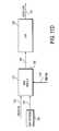
- FIG. 10illustrates an example of the embodiment or apparatus of the invention, comprising a processor circuit 50 .
- Circuit 50may be part of an integrated circuit, which receives video in analog and or digital form.
- Circuit 50outputs an analog video signal that provides a copy protection effect and reduces the effectiveness of a circumvention device.
- the apparatusmay include control bit(s) to configure (any of the) various versions of the inventive waveforms (e.g. FIGS. 2A , 2 B, 5 A, 6 A, and or 9 A) and or to enable or to disable any version of the copy protection signal at the analog output of processor circuit 50 .
- digital videomay be coupled to an input of processor circuit 50 , which may include one or more waveform circuits (e.g., fixed or programmable) to synthesize one or more negative going pulse, or one or more pulse pair signal including sync/pseudo sync and AGC pulse.
- the negative going pulse(s)are included immediately following, or in the next line after, a vertical sync signal, or a first/second line after a vertical sync signal that is typically outside a sync interval or location.
- Circuit 50may include an encoder and or digital to analog converter to provide an analog signal of one or more TV standards.
- the analog signalmay include a copy protection signal that is resistant to black boxes, a copy protection signal that causes a black box to further discourage copying and or to cause the black box in conjunction with the copy protection signal to provide a synergistic copy protection effect.
- a synergistic effectmay include passing one or more copy protection signals or pulses to the output of the circumvention device, which causes darkening or other copy protection effects on a recording, while causing the circumvention device to implement one or more of the following artifacts:
- a loss of program video information in one or more active TV linewhich can include darkening or a blanking near or at the top of the display (or from a recorder).
- Color unlocking or color distortione.g., errors in hue and or saturation
- Color unlocking or color distortionin one or more active TV lines, which can lead to incorrect color displayed on one or more lines near or at the top of the display, or loss of color for one or more lines near the top of the display.
- Recordersmay also exhibit extra color unlocking (or color distortion) upon record and or playback.
- New or increased playability artifact(s) when coupled to a TV displaywhich can include both (or either) color and extra darkening (or blanking and or attenuating) effects on a TV display and or a recorder.
- Processor circuit 50may include control bits or one or more bit patterns to enable, configure, and or disable at least a portion of the copy protection signal.
- FIG. 10Also illustrated in FIG. 10 is an exemplary prior art circumvention device (“black box”) 52 (e.g., a circumvention device with a timing circuit 22 ′ or 22 ′′), a recorder 54 coupled to the prior art circumvention device 52 , and a first display 56 that is coupled to the recorder. Also shown is a second display 58 coupled to an output of circumvention device 52 .
- black boxe.g., a circumvention device with a timing circuit 22 ′ or 22 ′′
- recorder 54coupled to the prior art circumvention device 52
- first display 56that is coupled to the recorder.
- second display 58coupled to an output of circumvention device 52 .
- Dashed line 60depicts a “bypass” mode where the new copy protection signal is coupled directly to recorder 54 and display 58 .
- the new copy protection signalhas little or no artifacts displayed on display 58 .
- recorder 54 and a playback monitorshow a darkened playback of an illegal copy, or other copy protection effects such as, for example, AGC gain variation or effect, brightness change, and or turning off (for a compliant device) the recording/viewing process.
- the circumvention device's input 62is coupled to a video source (via processor circuit 50 ) with the new copy protection signal(s) of the invention.
- circumvention device 52then outputs a video signal with a copy protection signal, which in turn causes recorder 54 to exhibit copy protection-effect(s) such as darkening, AGC effect, brightness change, and or shutting down (e.g., compliant device will shut down recording or viewing), and one or more of the following problems:
- a clamp error in a portion of the program video signalis a clamp error in a portion of the program video signal.
- a loss of color burst in one or more active TV linesis a loss of color burst in one or more active TV lines.
- a loss of program video information in one or more active TV linesis a loss of program video information in one or more active TV lines.
- a color unlocking or color distortion in one or more active TV linesis a color unlocking or color distortion in one or more active TV lines.
- a new or increased playability artifact(s) when coupled to a TV displayis a new or increased playability artifact(s) when coupled to a TV display.
- the new copy protection signalcauses more problems for a video pirate than without the circumvention device.
- the new copy protection signalcauses the circumvention device to enhance the copy protection effect, thereby discouraging the making of illegal copies of video programs.
- one or more of the new copy protection processesprovide resistance to circumvention device(s) (black boxes) or provide enhancement of or synergy to the copy protection process (or effectiveness).
- the new copy protection signal embodimentsalso reduce playability problems in some monitors. For example, by shifting the copy protection signals toward the vertical sync signal, an overshoot or ringing error in the TV set's phase lock loop feedback system settles down better by the time an active field is displayed.
- This better settling time in the horizontal scanning circuits of a TV setis especially applicable to copy protection signals where there is a position and or pulse-width modulation in the pseudo sync or AGC pulses from one TV line to another, or where the number of pseudo sync or AGC pulses changes from one TV line to another.
- a better settling time in a horizontal display or scanning systemprovides improved playability of the copy protection signal.
- a prior art waveform(e.g., for PAL or NTSC) that is shifted or moved (e.g., advanced) toward the vertical sync signal, provides better playability.
- copy protection signalssuch as pseudo sync and or AGC pulses that are provided further away from the active field provide less noticeable hooking or tearing at the top of a display screen or in a portion of the overscan area.
- one 625 line standard, prior art copy protection signalhas a Format A that has seven pulse pairs (pseudo sync/AGC) on line 8 (and or lines 10 , 12 , 14 , 16 ), which is then followed by Format B that has six pulse pairs on line 9 (and or lines 11 , 13 , 15 ).
- Format Ais 1.63 microseconds ( ⁇ 100 ns) wide for pseudo sync and 7 pseudo sync pulses per line, and or Format B having 1.78 microseconds ( ⁇ 100 ns) for pseudo sync and 6 pseudo sync pulses per line, or vice versa. Other numbers or values can be provided.
- This prior art signalthen does not have resistance to certain black boxes and or can be improved in playability.
- one or more embodiments of the inventioninclude(s) shifting either (or both) formats A and/or B one or two lines toward the vertical sync signal such as:
- Adding/inserting/synthesizing a Format A or Format B copy protection signal(e.g., starting) on lines 6 , 7 and/or 8 and/or lines 318 and/or 319 .
- (including) lines 6 , 8 , 10 , 12 , and or 14 (and/or 16 )may be of Format A (or B), while (including) lines 7 , 9 , 11 , 13 , and or 15 may be of Format B (or A).
- Format Arepresents a set of pseudo sync and or AGC pulses
- Format Brepresents another set of pseudo sync and or AGC pulses.
- any type of Format A and/or Format B signalsmay be provided in one or more selected TV lines, provided with a selected number of pulses (e.g., pseudo sync and or AGC) per line, or provided with selected pulse-width, pulse amplitude, and/or pulse position, for any of the added pulses (or sync pulse(s)).
- Format Aequals Format B, for example, for two or more consecutive lines.
- a copy protection process including two or more consecutive lines of (substantially) the same format toward the active fieldis one embodiment to improve playability or to still cause a problem with circumvention devices. For example, a process can start right after or delayed less than 2.5 lines after the vertical sync signal, with two formats interweaving/interlacing from one line to another.
- the last two or more lines that include pseudo syncs or copy protection signalsmay be a single format.
- One example embodiment of the inventionis to provide/include one or more (e.g., 4, 5, 6, or 7) pseudo sync or pseudo sync AGC pulses in three or more TV lines with at least one series of alternating formats in two (or more) lines (e.g., in consecutive lines), while providing two consecutive lines with substantially the same format.
- a series of TV linesmay include A′A′B′, B′A′A′, A′B′A′B′B′, A′A′B′A′B′, etc., where A′ and B′ each denote a particular format.
- each formatincludes a particular number of pseudo sync and or AGC pulses per line, and or includes pseudo sync and or AGC pulse width and or position.
- U.S. Pat. No. 6,836,549 by Quan and Brill issued on Dec. 28, 2004, incorporated by referencedescribes various methods and apparatuses for modulating in position, pulse width, and or amplitude of sync/pseudo sync and or AGC pulses, or changing the number of copy protection signals from one line to another, or gap-width modulation. Any embodiments of the invention may include one or more of the various methods apparatuses as described above for U.S. Pat. No. 6,836,549.
- any of the inventive processes/embodiments mentionede.g., copy protection signals that provide resistance to circumvention and or improved playability
- one or more of the followingmay be provided/generated/inserted/added for a (further) method or apparatus of the invention (e.g., combination).
- any of the copy protection pulsessuch as, for example, pseudo sync and or AGC pulses, by amplitude (e.g., may include a finite value and or zero amplitude), pulse-width, position, and or frequency (e.g., including changing a number of negative or positive going pulses from one video line to another line). Or providing at least one number (e.g., two or more (different) numbers) of pseudo sync and or AGC pulses per TV line interval in selected (e.g., two or more) TV lines.
- the modificationmay include phase, frequency, and or amplitude of one or more cycles of subcarrier, or may include adding cycles of subcarrier (e.g., widened (modified or unmodified) color burst envelope) or a reduced duration color burst envelope (modified or unmodified).
- cycles of subcarriere.g., widened (modified or unmodified) color burst envelope
- a reduced duration color burst envelopemodified or unmodified.
- segmentation of one or more color burst envelopes with two or more phasese.g., normal and non-normal phase
- adding extra cycles of subcarrier in one or more horizontal blanking intervalswhich can provide an extended (modified) color burst.
- sync position and or widthmay be altered.
- Providing dynamic blanking or modification of a video signale.g., one or more active field video line or one or more color burst in an active field
- a circumvention deviceby changing or modifying/modulating negative going pulses in a portion of the vertical blanking interval. For example, if negative going pulses near the vertical sync signal are provided or removed (or changed in position, amplitude, or width) as a function of time, the circumvention device will blank a portion of active (field) video lines (and or pass through one or more copy protection signal) when the negative pulses are provided, and then not blank a portion of active (field) video lines (while reducing an effect of the copy protection signal(s)) when the negative pulses are not provided.
- An illustration of providing dynamic copy protection signal or effect via a circumvention devicewould be to alternate/switch in time prior art signals of FIG. 1A or 1 B and inventive signals of FIG. 2A or 2 B.
- the output of the circumvention devicewill then generate a newly provided amplitude modulated (effect) of copy protection signals by modulating (in one to three lines) negative going pulses after a vertical sync signal.
- FIGS. 11A through 11Dillustrate example apparatuses or systems for implementing the various waveforms of the invention.
- video(analog or digital) is coupled to an input 71 .
- a timing generator circuit 77receives the video signal via input 71 , and produces one or more various timing signals for selected pixels/selected video lines such as provided by leads 72 , 73 , 74 , 75 , and or 76 .
- lead 72produces a timing signal for providing positive going pulses such as AGC pulses in selected video (TV) lines and selected pixels.
- the timing signal on lead 72for instance (in the VBI) can provide a logic high signal for selected pixels on (any combination of) TV lines 317 (or 6), 318 (or 7), and or up to 327 (16) for a 625 line TV standard system, which when coupled to positive pulse generator 82 , provides AGC or positive going pulses to a video output 91 of combiner, DAC and or encoder circuit 90 .
- the video line allocationmay include any combination of video lines from 10 - 20 and/or 272 - 283 .
- Any of the positive going (e.g., AGC) pulsesmay be modulated in position, amplitude, and or pulse-width (e.g., within an interval or from one TV line to another) via an optional modulator circuit 87 (shown in dashed line).
- lead 72may include providing an AGC or positive going pulse in a portion of the back porch, or a portion of a horizontal blanking interval, of selected TV lines (e.g., providing back porch pulses).
- the selected linesmay include one or more TV lines in an overscan area, such as bottom of the TV field, a portion of the VBI, and or a top of the TV field.
- These back porch pulsesmay be modulated in position, amplitude, and or pulse-width from one TV line to another via the optional modulator circuit 87 .
- amplitude modulationmay be applied to one or more of the back porch pulses.
- a signal for selected TV lines and pixels for providing negative going pulses for one or more embodiments of the inventionis illustrated by signal lead 73 that is coupled to a negative pulse generator 83 .
- the negative going pulsesmay include the allocation of TV lines mentioned for signal lead 72 above.
- signal leads 72 and or 73(via setting the selected pixels) can provide a different number of pulses, positive and or negative going pulses, a position change, and or a pulse-width change.
- the signalscan provide position modulation and or pulse width modulation of pseudo sync and or AGC pulses, from one TV line to another (e.g., in the VBI) for a video output such as on output terminal/connection 91 .
- an enhancement signalmay be added.
- a selected line and or pixel signal lead 74may provide an enhancement circuit 84 with an increased or modified copy protection effect via the circuit 90 and output 91 .
- signal lead 74provides selected lines and pixels to lower or to level shift (e.g., level shift up or down) at least a portion of the active video signal, and or level shift at least a portion of the front and or back porch region.
- the copy protection effect or copy protection signalis modified or enhanced.
- one or more portions of one or more active field line(s)is shifted or lowered in black or blanking level compared to the blanking or black level of one or more TV lines in a portion of the VBI.
- This color burst modificationmay include segmentation of phases and or amplitudes for providing a modified color burst in one or more horizontal blanking interval(s).
- the timing generator 77provides a signal on signal lead 75 that allows selected lines and pixels to be modified such that a modified color burst is synthesized via a color burst modifier circuit 85 and circuit 90 .
- Circuit 85receives a signal on lead 75 to generate a modified color burst for selected lines and portion of the horizontal blanking interval (HBI).
- the output of circuit 85may include an analog signal or digital signal.
- circuit 85may include a color subcarrier generator, which provides a PAL or NTSC modified color burst on selected TV lines and generally normal color burst on another set of TV lines.
- circuit 85may output digital signals to a digital color (subcarrier) encoder such as one that would be included in circuit 90 to provide a color burst signal at output 91 that is modified for one set of TV lines and substantially normal color burst on another set of TV lines.
- the digital color (subcarrier) encodermay provide component video signals (e.g., R-Y, B-Y, I, or Q signals), which are modified in selected TV lines and pixels (e.g., in an HBI portion) to a color subcarrier encoder.
- the encoderencodes a modified PAL and or NTSC color burst signal such as, for example, color stripe, split burst color stripe, segmented phase/amplitude color burst signal, widened or narrowed color burst or color stripe envelope, and or advanced or delayed color burst or color stripe signal.
- a signal lead 76provides a logic signal for selected lines and pixels to generate sync pulses of amplitude, position, level shifting, and or pulse-width via sync a generator circuit 86 .
- the copy protection or copy protection effectmay be increased in effectiveness or modified via sync amplitude reduction and or sync width reduction on one or more TV lines.
- the output of circuit 86is then coupled to the circuit 90 to provide a TV signal with one or more modified horizontal and or vertical sync pulse/signal.
- the input on lead 79may provide one or more waveforms such as a negative going pulse, a positive going pulse, an enhancement or modification signal (level shifting one or more portions of a video signal), color burst modification, and or sync modification, or may provide configuring/enabling/disabling the negative and or positive going pulses, or may configure/program/enable/disable an enhancement signal, color burst signal, and or sync signals.
- the input on lead 79may provide one or more waveforms such as a negative going pulse, a positive going pulse, an enhancement or modification signal (level shifting one or more portions of a video signal), color burst modification, and or sync modification, or may provide configuring/enabling/disabling the negative and or positive going pulses, or may configure/program/enable/disable an enhancement signal, color burst signal, and or sync signals.
- FIG. 11Billustrates another apparatus, which receives an analog or digital signal at input 101 .
- the input 101is coupled to a timing circuit 102 , which outputs horizontal and vertical reference signals 104 and 105 respectively. These reference signals 104 and 105 are then coupled to a pseudo sync pulse generator and AGC pulse generator circuit 103 .
- the timing circuit 102may also provide a pixel clock reference 107 to the circuit 103 .
- the reference timing signals and also the input signalare coupled to circuit 103 which then provides a video signal with pseudo sync pulses and or AGC pulses at an output 106 that causes certain black boxes to pass at least some of the pseudo sync or pseudo sync and AGC pulses.
- Circuit 103may include control or programming from one or more control or programming signals or bit(s) or bit pattern(s) as depicted at an input 108 .
- control bit, or bit pattern 108line location, pulse width, pulse position, and or amplitude of pseudo sync and or AGC pulses may be set as by one or more bit pattern(s).
- a control signal or control bitmay enable/disable and or program any of the inventive waveforms and or any other waveform (e.g., enhancement signal, color burst modification, sync modification, etc.) that may be combined with an embodiment of the invention.
- FIG. 11Cillustrates a processor (circuit) 115 supplied with an input video signal on line 112 (analog or digital) and a timing signal on a line 116 .
- Processor 115includes a generator and or modulator.
- the modulatormay modulate pulse width, pulse position, gap width such as between a negative going pulse and a positive going pulse, and or may modulate the amplitude of AGC pulses and or sync/pseudo sync pulses.
- the pseudo sync and or AGC pulsesmay be position or pulse width modulated within a video line or from one video line to another.
- the copy protection pulsessuch as AGC pulses may include amplitude modulation.
- An example output of processor 115is a signal on output 114 , which may include static or dynamically modulated copy protection waveform(s), which defeats or reduces one or more effects of a black box, which provides resistance to certain black boxes and or which improves on playability.
- Processor 115may (also) include an enabling, disabling, and or programmability (control) bit or signal on an input 113 such as previously mentioned for example in FIG. 11A and or FIG. 11B .
- FIG. 11Dillustrates an apparatus for use in the digital domain.
- a digital video signalis coupled to an input 122 of a switching or multiplex (MUX) circuit 121 .
- Another input 123supplies a bit pattern signal from a bit pattern generator 128 , which provides digital words or bytes (or a bit pattern) that switch in various levels to provide negative going and or positive going pulses at an output 127 of a digital to analog converter 126 .
- the circuit 121also is supplied with a switch or multiplex control signal on an input 125 , which is enabled during one or more portions of the VBI and or HBI.
- the bit pattern generator 128is switched in by the control input 125 .
- Generator/source 128provides a digital signal such that when circuit 121 is coupled to the digital to analog converter (D/A) 126 , pseudo sync and or AGC pulses are provided to the video signal on input 122 with one or more pseudo sync pulses and or AGC pulses from zero to about 1.5 TV line(s) after a post equalizing pulse or after a vertical sync signal, wherein the vertical sync signal includes pre-equalizing syncs, broad sync pulses, and post equalizing syncs.
- generator 128can provide a bit pattern which provides an AGC pulse (and/or negative going pulse) in a portion of the back porch, or HBI of selected TV lines on the video output 127 .
- a method of providing a video copy protection signal to a video signal to form a copy protected video signal which causes a circumvention device to pass at least some of the video copy protection signal at the output of the circumvention deviceincludes inserting or adding, in at least one TV line, one or more pseudo sync pulses, or one or more pseudo sync pulse/AGC pulse pair signals immediately after a vertical sync signal, or delayed one line or delayed less than 2 lines after a vertical sync signal. It follows that the copy protected video signal is substantially effective in providing copy protection or content control after passing through the circumvention device, contrary to the intended function of the circumvention device.
- At least one TV line with one or more pseudo sync pulse and or AGC pulseincludes up to 18 TV lines including one or more pseudo sync pulse and or AGC pulse per TV line, or wherein the number of pseudo sync and or AGC pulses changes from one TV line to another TV line.
- the copy protected video signalis a composite, component, PAL, or NTSC or SECAM copy protected video signal, or wherein horizontal sync(s), the pseudo sync(s), and or AGC signal(s) are position, pulse-width, and or amplitude modulated from one TV line to another TV line, or within a TV line.
- the circumvention deviceadds or enhances copy protection effectiveness after processing the copy protected signal.
- the circumvention devicefurther blanks out color burst signals in one or more TV lines in the active TV field.
- one or more TV lines in the active TV fieldexhibit color distortion via the circumvention device.
- the copy protected signalincludes improved playability over a copy protected video signal which inserts pseudo sync pulses two or more lines after the vertical sync signal.
- An apparatus for providing a video copy protection signal to a video signal to form a copy protected video signal which causes a circumvention device to pass at least some of the video copy protection signal at the output of the circumvention deviceincludes a processing circuit receiving a video signal, for inserting or adding one or more pseudo sync pulses or pseudo sync/AGC pulse pair signals in at least one TV line immediately after, or one line or less than 2 lines after, a vertical sync signal, to provide the copy protected video signal.
- the inventioninvolves providing a copy protection signal including pseudo sync and AGC pulses for a pulse pair signal, wherein a location of the pseudo sync pulses provides resistance to a circumvention device and wherein the circumvention devices passes at least one pulse pair signal, and wherein the location of pseudo sync signals start immediately after or less than 2 or 2.5 lines after a vertical sync signal.
- the inventionincludes one or more of the following: a color burst modification of whole or segmented sections of one or more color burst envelope which includes one or more cycles of incorrect color burst, level shifting a portion of the video signal including lowering or raising one or more portions of the video signal, modifying sync location, amplitude, and or pulse width at selected TV lines, providing back porch pulses of different video levels from one line to another, providing pseudo sync and or AGC pulses of different pulse widths from one line to another, providing pseudo sync and or AGC pulses of different numbers from one line to another.
- the inventionincludes providing a copy protection signal, wherein the copy protection signal causes a circumvention device to modify the video signal so as to increase copy protection effectiveness while passing at least part of the copy protection signal to maintain copy protection effectiveness from the copy protection signal.
- the increased effectiveness provided by the circumvention deviceincludes modifying one or more color burst signals to cause new color distortion and or blanking/modifying a portion of the visible view area, by starting the copy protection signals immediately after or less than 2 or 2.5 lines after a vertical sync signal.
- the inventionincludes increasing color copy protection effects of a copy protection signal provided by a circumvention device, wherein the copy protection signal includes color burst modification in selected TV lines, and wherein the color burst modification causes a recorder or TV set to produce color distortion.
- the inventionincludes combining pseudo sync and or pseudo sync and or AGC pulses immediately after or less than 2 or 2.5 lines after a vertical sync signal with the color burst modification, wherein the color burst modification includes cycles of incorrect phase or frequency in selected TV lines, and wherein the circumvention device outputs a copy protection signal which produces color distortions of the modified color burst in the copy protection signal and extra color distortion due to blanking or modifying color burst envelopes in an active field caused by the circumvention device.
- the circumvention devicesenses the pseudo sync signals to cause incorrect blanking or modification of the copy protection signal, which may include passing some or all of the pseudo sync and or AGC signals to the output of the circumvention device.
- Circuitry for any of the above embodiments, methods, and or apparatusesmay be included in an integrated circuit or part of an integrated circuit.
- Media players, tuners, optical storage players or recorders, hard drive or magnetic storage players or recorders, solid state memory recorders or players, receivers, recorders, cell phones, TV sets, etc.may include the integrated circuit or circuitry to provide at least a part of any of the inventive waveforms or embodiments, that, for example, provide resistance to certain circumvention devices and or improve playability, such as, for example, over prior art copy protection signals such as in terms of improving playability via less hooking or via less scanning error on a TV display.
Landscapes
- Engineering & Computer Science (AREA)
- Multimedia (AREA)
- Signal Processing (AREA)
- Computer Security & Cryptography (AREA)
- Television Signal Processing For Recording (AREA)
- Signal Processing Not Specific To The Method Of Recording And Reproducing (AREA)
Abstract
Description
Claims (22)
Priority Applications (2)
| Application Number | Priority Date | Filing Date | Title |
|---|---|---|---|
| US12/322,004US8280049B2 (en) | 2008-08-27 | 2009-01-28 | Method and apparatus for synthesizing copy protection for reducing/defeating the effectiveness or capability of a circumvention device |
| PCT/US2009/004730WO2010027409A2 (en) | 2008-08-27 | 2009-08-19 | Method and apparatus for synthesizing copy protection for reducing/defeating the effectiveness or capability of a circumvention device |
Applications Claiming Priority (2)
| Application Number | Priority Date | Filing Date | Title |
|---|---|---|---|
| US19025408P | 2008-08-27 | 2008-08-27 | |
| US12/322,004US8280049B2 (en) | 2008-08-27 | 2009-01-28 | Method and apparatus for synthesizing copy protection for reducing/defeating the effectiveness or capability of a circumvention device |
Publications (2)
| Publication Number | Publication Date |
|---|---|
| US20100054469A1 US20100054469A1 (en) | 2010-03-04 |
| US8280049B2true US8280049B2 (en) | 2012-10-02 |
Family
ID=41725470
Family Applications (2)
| Application Number | Title | Priority Date | Filing Date |
|---|---|---|---|
| US12/322,004Expired - Fee RelatedUS8280049B2 (en) | 2008-08-27 | 2009-01-28 | Method and apparatus for synthesizing copy protection for reducing/defeating the effectiveness or capability of a circumvention device |
| US12/583,834AbandonedUS20100054700A1 (en) | 2008-08-27 | 2009-08-26 | Method and apparatus for providing in a media player a copy protection signal that negates a circumvention device and or provides improved playability |
Family Applications After (1)
| Application Number | Title | Priority Date | Filing Date |
|---|---|---|---|
| US12/583,834AbandonedUS20100054700A1 (en) | 2008-08-27 | 2009-08-26 | Method and apparatus for providing in a media player a copy protection signal that negates a circumvention device and or provides improved playability |
Country Status (2)
| Country | Link |
|---|---|
| US (2) | US8280049B2 (en) |
| WO (1) | WO2010027409A2 (en) |
Cited By (1)
| Publication number | Priority date | Publication date | Assignee | Title |
|---|---|---|---|---|
| US10484671B2 (en) | 2015-05-29 | 2019-11-19 | Interdigital Ce Patent Holdings | Method for displaying a content from 4D light field data |
Families Citing this family (7)
| Publication number | Priority date | Publication date | Assignee | Title |
|---|---|---|---|---|
| US8280049B2 (en)* | 2008-08-27 | 2012-10-02 | Rovi Solutions Corporation | Method and apparatus for synthesizing copy protection for reducing/defeating the effectiveness or capability of a circumvention device |
| US8374489B2 (en)* | 2009-09-23 | 2013-02-12 | Rovi Technologies Corporation | Method and apparatus for inducing and or reducing geometric distortions in a display via positive going pulses |
| US20110081129A1 (en) | 2009-10-07 | 2011-04-07 | Rovi Technologies Corporation | Broadband recording method and apparatus for video and/or audio programs |
| US20110135277A1 (en)* | 2009-12-09 | 2011-06-09 | Rovi Technologies Corporation | Method and Apparatus for Providing in a Receiver a Copy Protection Signal That Negates a Circumvention Device and or Provides Improved Playability |
| US8374490B2 (en)* | 2010-02-24 | 2013-02-12 | Rovi Technologies Corporation | Method and apparatus for receiving metadata, EPG, or IPG signals in an integrated circuit for control purposes |
| US9049073B2 (en) | 2011-06-28 | 2015-06-02 | Rovi Guides, Inc. | Systems and methods for initializing allocations of transport streams based on historical data |
| US10687011B2 (en)* | 2016-03-28 | 2020-06-16 | Techpoint, Inc. | Method and apparatus for improving transmission of transport video signal |
Citations (41)
| Publication number | Priority date | Publication date | Assignee | Title |
|---|---|---|---|---|
| US4631603A (en)* | 1985-04-17 | 1986-12-23 | Macrovision | Method and apparatus for processing a video signal so as to prohibit the making of acceptable video tape recordings thereof |
| US4695901A (en)* | 1986-03-04 | 1987-09-22 | Macrovision | Method and apparatus for removing pseudo-sync and/or agc pulses from a video signal |
| US4907093A (en)* | 1986-08-11 | 1990-03-06 | Macrovision Corporation | Method and apparatus for preventing the copying of a video program |
| US5194965A (en)* | 1983-11-23 | 1993-03-16 | Macrovision Corporation | Method and apparatus for disabling anti-copy protection system in video signals |
| US5251041A (en)* | 1991-06-21 | 1993-10-05 | Young Philip L | Method and apparatus for modifying a video signal to inhibit unauthorized videotape recording and subsequent reproduction thereof |
| US5315448A (en) | 1993-03-18 | 1994-05-24 | Macrovision Corporation | Copy protection for hybrid digital video tape recording and unprotected source material |
| US5394470A (en)* | 1992-08-24 | 1995-02-28 | Eidak Corporation | Horizontal pulse augmentation of a video signal |
| US5479268A (en) | 1990-09-10 | 1995-12-26 | Starsight Telecast Inc. | User interface for television schedule system |
| US5579120A (en)* | 1993-10-08 | 1996-11-26 | Sony Corporation | Copyright protection for digital signal recording and/or reproduction and recording medium thereof |
| US5583936A (en)* | 1993-05-17 | 1996-12-10 | Macrovision Corporation | Video copy protection process enhancement to introduce horizontal and vertical picture distortions |
| US5651065A (en)* | 1995-03-09 | 1997-07-22 | General Instrument Corporation Of Delaware | Insertion of supplemental burst into video signals to thwart piracy and/or carry data |
| US5661801A (en)* | 1995-02-14 | 1997-08-26 | Hsn Marketing Inc. | Method and apparatus for stabilizing and brightening prerecorded TV signals encoded with copy protection |
| US5907656A (en)* | 1994-03-29 | 1999-05-25 | Sony Corporation | Apparatus and method for reproducing video signals with varying-magnitude AGC signals |
| US5953417A (en)* | 1995-10-17 | 1999-09-14 | Macrovision Corp | Method and apparatus for digitally removing or defeating effects of copy protection signals from a video signal |
| US6028941A (en)* | 1997-07-28 | 2000-02-22 | Scientific-Atlanta, Inc. | Method for the defeat of illegal descramblers sensitive to the edges of sync in scrambled video |
| US6058191A (en)* | 1997-02-04 | 2000-05-02 | Macrovision Corp | Method and apparatus for modifying the envelope of a RF carrier signal to remove copy protection signals therefrom |
| US6381747B1 (en) | 1996-04-01 | 2002-04-30 | Macrovision Corp. | Method for controlling copy protection in digital video networks |
| KR20020078344A (en) | 2001-04-09 | 2002-10-18 | 엘지전자 주식회사 | Syne detection circuit |
| US6516132B1 (en) | 1995-05-09 | 2003-02-04 | Macrovision Corp | Method and apparatus for improving the effects of color burst modifications to a video signal |
| US20030149980A1 (en) | 1998-09-17 | 2003-08-07 | United Video Properties, Inc., A Corporation Of Delaware | Electronic program guide with integrated program listings |
| US6690880B1 (en)* | 1999-05-21 | 2004-02-10 | Ati International, Srl | Method and apparatus for copy protection detection in a video signal |
| US20040174798A1 (en) | 2001-02-09 | 2004-09-09 | Michel Riguidel | Data copy-protecting system for creating a copy-secured optical disc and corresponding protecting method |
| US6836549B1 (en)* | 1998-09-02 | 2004-12-28 | Macrovision Corporation | Method and apparatus for synthesizing and reducing the effects of video copy protection signals |
| US6839433B1 (en)* | 1998-07-22 | 2005-01-04 | Macrovision Corporation | Method and apparatus for generating a signal that defeats illegal cable decoders |
| US6931547B2 (en)* | 2001-01-03 | 2005-08-16 | Macrovision Corporation | Method and apparatus for identifying a vertical blanking interval in a television signal |
| US20060056809A1 (en)* | 2000-08-15 | 2006-03-16 | Ronald Quan | Method and apparatus for synthesizing or modifying a copy protection signal using a lowered signal level portion |
| US20060083373A1 (en) | 2004-10-19 | 2006-04-20 | Macrovision Corporation | System and method for allowing copying or distribution of a copy protected signal |
| US20060085863A1 (en) | 2004-10-19 | 2006-04-20 | Macrovision Corporation | Method and apparatus for storing copy protection information separately from protected content |
| US7039294B2 (en) | 1995-05-09 | 2006-05-02 | Macrovision Corporation | Method and apparatus for modifying the effects of color burst modifications to a video signal |
| US20060251252A1 (en) | 2005-05-06 | 2006-11-09 | Macrovision Corporation | Method and apparatus for modifying a subsequently generated control command in a content control system |
| US7352864B2 (en)* | 2002-03-26 | 2008-04-01 | Sanyo Electric Co., Ltd. | Display device |
| US20080100597A1 (en) | 2006-10-25 | 2008-05-01 | Macrovision Corporation | Method and apparatus to improve playability in overscan areas of a TV display |
| US7395545B2 (en) | 1997-03-31 | 2008-07-01 | Macrovision Corporation | Method and apparatus for providing copy protection using a transmittal mode command |
| US20090052866A1 (en)* | 2007-08-22 | 2009-02-26 | Macrovision Corporation | Method and apparatus for synthesizing a copy protection or content control signal with improved playability of a TV set |
| USRE40689E1 (en)* | 1983-11-23 | 2009-03-31 | Macrovision Corporation | Method and apparatus for disabling anti-copy protection system in video signals |
| US20090327717A1 (en) | 2006-12-08 | 2009-12-31 | International Business Machines Corporation | System, method, and service for tracing traitors from content protection circumvention devices |
| US20100054700A1 (en)* | 2008-08-27 | 2010-03-04 | Rovi Technologies Corporation | Method and apparatus for providing in a media player a copy protection signal that negates a circumvention device and or provides improved playability |
| US20100107201A1 (en) | 2004-07-21 | 2010-04-29 | Comcast Ip Holdings I, Llc | Media content modification and access system for interactive access of media content across disparate network platforms |
| US20110135277A1 (en)* | 2009-12-09 | 2011-06-09 | Rovi Technologies Corporation | Method and Apparatus for Providing in a Receiver a Copy Protection Signal That Negates a Circumvention Device and or Provides Improved Playability |
| US8019201B2 (en)* | 2002-06-28 | 2011-09-13 | Dcs Copy Protection Limited | Method and apparatus for providing a copy-protected video signal |
| US20110225603A1 (en) | 2008-05-01 | 2011-09-15 | At&T Intellectual Property I, L.P. | Avatars in Social Interactive Television |
Family Cites Families (1)
| Publication number | Priority date | Publication date | Assignee | Title |
|---|---|---|---|---|
| JP3694981B2 (en)* | 1996-04-18 | 2005-09-14 | ソニー株式会社 | Video signal processing apparatus and video signal processing method |
- 2009
- 2009-01-28USUS12/322,004patent/US8280049B2/ennot_activeExpired - Fee Related
- 2009-08-19WOPCT/US2009/004730patent/WO2010027409A2/enactiveApplication Filing
- 2009-08-26USUS12/583,834patent/US20100054700A1/ennot_activeAbandoned
Patent Citations (64)
| Publication number | Priority date | Publication date | Assignee | Title |
|---|---|---|---|---|
| US5194965A (en)* | 1983-11-23 | 1993-03-16 | Macrovision Corporation | Method and apparatus for disabling anti-copy protection system in video signals |
| USRE40689E1 (en)* | 1983-11-23 | 2009-03-31 | Macrovision Corporation | Method and apparatus for disabling anti-copy protection system in video signals |
| US4631603A (en)* | 1985-04-17 | 1986-12-23 | Macrovision | Method and apparatus for processing a video signal so as to prohibit the making of acceptable video tape recordings thereof |
| US4695901A (en)* | 1986-03-04 | 1987-09-22 | Macrovision | Method and apparatus for removing pseudo-sync and/or agc pulses from a video signal |
| US4695901B1 (en)* | 1986-03-04 | 1990-10-02 | Macrovision | |
| US4907093A (en)* | 1986-08-11 | 1990-03-06 | Macrovision Corporation | Method and apparatus for preventing the copying of a video program |
| US5479268A (en) | 1990-09-10 | 1995-12-26 | Starsight Telecast Inc. | User interface for television schedule system |
| US5251041A (en)* | 1991-06-21 | 1993-10-05 | Young Philip L | Method and apparatus for modifying a video signal to inhibit unauthorized videotape recording and subsequent reproduction thereof |
| US5394470A (en)* | 1992-08-24 | 1995-02-28 | Eidak Corporation | Horizontal pulse augmentation of a video signal |
| US5315448A (en) | 1993-03-18 | 1994-05-24 | Macrovision Corporation | Copy protection for hybrid digital video tape recording and unprotected source material |
| US7352863B2 (en)* | 1993-05-17 | 2008-04-01 | Macrovision Corporation | Copy protection for video signal using narrowed horizontal synchronization signals and amplitude modulation |
| US7706533B2 (en) | 1993-05-17 | 2010-04-27 | Macrovision Corporation | Copy protection for video signal using narrowed horizontal synchronization signals |
| US5633927A (en)* | 1993-05-17 | 1997-05-27 | Macrovision Corporation | Video copy protection process enhancement to introduce horizontal and vertical picture distortions |
| US6501842B2 (en)* | 1993-05-17 | 2002-12-31 | Macrovision Corporation | Method and apparatus for modifying a video signal by back porch lowering |
| US20100021133A1 (en) | 1993-05-17 | 2010-01-28 | Macrovision Corporation | Method for copy protection for video signal with added pulses |
| US5748733A (en)* | 1993-05-17 | 1998-05-05 | Macrovision Corporation | Method and apparatus to reduce effects of certain copy protection purses within a video signal |
| US7492896B2 (en)* | 1993-05-17 | 2009-02-17 | Macrovision Corporation | Copy protection for video signal using added negative amplitude pulse |
| US7085380B2 (en)* | 1993-05-17 | 2006-08-01 | Macrovision Corporation | Method for modifying a copy protected video signal with a negative amplitude pulse |
| US20070206794A1 (en)* | 1993-05-17 | 2007-09-06 | Wonfor Peter J | Copy protection for video signal added pulses |
| US5625691A (en)* | 1993-05-17 | 1997-04-29 | Macrovision Corporation | Method and apparatus to defeat certain copy protection pulses within a video signal |
| US20080025696A1 (en) | 1993-05-17 | 2008-01-31 | Wonfor Peter J | Video copy protection process enhancement to introduce horizontal and vertical picture distortions |
| US7620178B2 (en) | 1993-05-17 | 2009-11-17 | Macrovision Corporation | Copy protection for video signal added pulses |
| US6285765B1 (en) | 1993-05-17 | 2001-09-04 | Macrovision Corporation | Method and apparatus for reducing effects of copy protection of composite video signal |
| US5583936A (en)* | 1993-05-17 | 1996-12-10 | Macrovision Corporation | Video copy protection process enhancement to introduce horizontal and vertical picture distortions |
| US5579120A (en)* | 1993-10-08 | 1996-11-26 | Sony Corporation | Copyright protection for digital signal recording and/or reproduction and recording medium thereof |
| US5907656A (en)* | 1994-03-29 | 1999-05-25 | Sony Corporation | Apparatus and method for reproducing video signals with varying-magnitude AGC signals |
| US5661801A (en)* | 1995-02-14 | 1997-08-26 | Hsn Marketing Inc. | Method and apparatus for stabilizing and brightening prerecorded TV signals encoded with copy protection |
| US5651065A (en)* | 1995-03-09 | 1997-07-22 | General Instrument Corporation Of Delaware | Insertion of supplemental burst into video signals to thwart piracy and/or carry data |
| US6516132B1 (en) | 1995-05-09 | 2003-02-04 | Macrovision Corp | Method and apparatus for improving the effects of color burst modifications to a video signal |
| US7039294B2 (en) | 1995-05-09 | 2006-05-02 | Macrovision Corporation | Method and apparatus for modifying the effects of color burst modifications to a video signal |
| US6421497B1 (en)* | 1995-10-17 | 2002-07-16 | Macrovision Corporation | Method for locating copy protection pulses within selected video lines of a video signal |
| US6173109B1 (en)* | 1995-10-17 | 2001-01-09 | Macrovision Corporation | Method and apparatus for removing or defeating effects of copy protection signals from a video signal |
| US6002830A (en)* | 1995-10-17 | 1999-12-14 | Macrovision Corporation | Method and apparatus for removing or defeating effects of copy protection signals from a video signal |
| US5953417A (en)* | 1995-10-17 | 1999-09-14 | Macrovision Corp | Method and apparatus for digitally removing or defeating effects of copy protection signals from a video signal |
| US6381747B1 (en) | 1996-04-01 | 2002-04-30 | Macrovision Corp. | Method for controlling copy protection in digital video networks |
| US6058191A (en)* | 1997-02-04 | 2000-05-02 | Macrovision Corp | Method and apparatus for modifying the envelope of a RF carrier signal to remove copy protection signals therefrom |
| US20080178235A1 (en) | 1997-03-31 | 2008-07-24 | Wonfor Peter J | Method and apparatus for providing copy protection using a transmittal mode command |
| US7395545B2 (en) | 1997-03-31 | 2008-07-01 | Macrovision Corporation | Method and apparatus for providing copy protection using a transmittal mode command |
| US6028941A (en)* | 1997-07-28 | 2000-02-22 | Scientific-Atlanta, Inc. | Method for the defeat of illegal descramblers sensitive to the edges of sync in scrambled video |
| US6839433B1 (en)* | 1998-07-22 | 2005-01-04 | Macrovision Corporation | Method and apparatus for generating a signal that defeats illegal cable decoders |
| US8094818B2 (en)* | 1998-09-02 | 2012-01-10 | Rovi Solutions Corporation | Method to synthesize video copy protection signals |
| US20050117749A1 (en)* | 1998-09-02 | 2005-06-02 | Ronald Quan | Method and apparatus to synthesize and defeat video copy protection signals |
| US6836549B1 (en)* | 1998-09-02 | 2004-12-28 | Macrovision Corporation | Method and apparatus for synthesizing and reducing the effects of video copy protection signals |
| US20030149980A1 (en) | 1998-09-17 | 2003-08-07 | United Video Properties, Inc., A Corporation Of Delaware | Electronic program guide with integrated program listings |
| US7603025B2 (en)* | 1999-05-21 | 2009-10-13 | Ati Technologies Srl | Method and apparatus for copy protection detection in a video signal |
| US6690880B1 (en)* | 1999-05-21 | 2004-02-10 | Ati International, Srl | Method and apparatus for copy protection detection in a video signal |
| US7050698B1 (en)* | 2000-08-15 | 2006-05-23 | Macrovision Corporation | Method and apparatus for synthesizing or modifying a copy protection signal using a lowered signal level portion |
| US20060056809A1 (en)* | 2000-08-15 | 2006-03-16 | Ronald Quan | Method and apparatus for synthesizing or modifying a copy protection signal using a lowered signal level portion |
| US6931547B2 (en)* | 2001-01-03 | 2005-08-16 | Macrovision Corporation | Method and apparatus for identifying a vertical blanking interval in a television signal |
| US7100209B2 (en)* | 2001-01-03 | 2006-08-29 | Macrovision Corporation | Method to provide the generation of an incorrect or unreliable vertical/frame rate signal |
| US20040174798A1 (en) | 2001-02-09 | 2004-09-09 | Michel Riguidel | Data copy-protecting system for creating a copy-secured optical disc and corresponding protecting method |
| KR20020078344A (en) | 2001-04-09 | 2002-10-18 | 엘지전자 주식회사 | Syne detection circuit |
| US7352864B2 (en)* | 2002-03-26 | 2008-04-01 | Sanyo Electric Co., Ltd. | Display device |
| US8019201B2 (en)* | 2002-06-28 | 2011-09-13 | Dcs Copy Protection Limited | Method and apparatus for providing a copy-protected video signal |
| US20100107201A1 (en) | 2004-07-21 | 2010-04-29 | Comcast Ip Holdings I, Llc | Media content modification and access system for interactive access of media content across disparate network platforms |
| US20060085863A1 (en) | 2004-10-19 | 2006-04-20 | Macrovision Corporation | Method and apparatus for storing copy protection information separately from protected content |
| US20060083373A1 (en) | 2004-10-19 | 2006-04-20 | Macrovision Corporation | System and method for allowing copying or distribution of a copy protected signal |
| US20060251252A1 (en) | 2005-05-06 | 2006-11-09 | Macrovision Corporation | Method and apparatus for modifying a subsequently generated control command in a content control system |
| US20080100597A1 (en) | 2006-10-25 | 2008-05-01 | Macrovision Corporation | Method and apparatus to improve playability in overscan areas of a TV display |
| US20090327717A1 (en) | 2006-12-08 | 2009-12-31 | International Business Machines Corporation | System, method, and service for tracing traitors from content protection circumvention devices |
| US20090052866A1 (en)* | 2007-08-22 | 2009-02-26 | Macrovision Corporation | Method and apparatus for synthesizing a copy protection or content control signal with improved playability of a TV set |
| US20110225603A1 (en) | 2008-05-01 | 2011-09-15 | At&T Intellectual Property I, L.P. | Avatars in Social Interactive Television |
| US20100054700A1 (en)* | 2008-08-27 | 2010-03-04 | Rovi Technologies Corporation | Method and apparatus for providing in a media player a copy protection signal that negates a circumvention device and or provides improved playability |
| US20110135277A1 (en)* | 2009-12-09 | 2011-06-09 | Rovi Technologies Corporation | Method and Apparatus for Providing in a Receiver a Copy Protection Signal That Negates a Circumvention Device and or Provides Improved Playability |
Non-Patent Citations (1)
| Title |
|---|
| International Search Report for International application No. PCT/US2009/004730, mailed Apr. 12, 2010, 1 page. |
Cited By (1)
| Publication number | Priority date | Publication date | Assignee | Title |
|---|---|---|---|---|
| US10484671B2 (en) | 2015-05-29 | 2019-11-19 | Interdigital Ce Patent Holdings | Method for displaying a content from 4D light field data |
Also Published As
| Publication number | Publication date |
|---|---|
| US20100054700A1 (en) | 2010-03-04 |
| WO2010027409A2 (en) | 2010-03-11 |
| WO2010027409A3 (en) | 2010-06-17 |
| US20100054469A1 (en) | 2010-03-04 |
Similar Documents
| Publication | Publication Date | Title |
|---|---|---|
| US8280049B2 (en) | Method and apparatus for synthesizing copy protection for reducing/defeating the effectiveness or capability of a circumvention device | |
| US7664369B2 (en) | Method and apparatus for improving the playability of a PAL or NTSC video signal containing color burst modifications | |
| EP0802676B1 (en) | Video copy protection | |
| CA2605857C (en) | Method and apparatus for modifying a subsequently generated control command in a content control system | |
| US20100178032A1 (en) | Method and apparatus for providing a copy protected analog video signal via a DAC | |
| US8542980B2 (en) | Anti-copy protection for a video signal | |
| CN101569208B (en) | Method and apparatus for improving playability in the overscan region of a television display | |
| EP1310093B1 (en) | Method and apparatus for enhancing chroma distortion in a video copy protection signal | |
| US8355621B2 (en) | Content management for a video signal | |
| US20110135277A1 (en) | Method and Apparatus for Providing in a Receiver a Copy Protection Signal That Negates a Circumvention Device and or Provides Improved Playability | |
| US8498519B2 (en) | Copy protection method and apparatus | |
| US8644680B2 (en) | Method and apparatus for providing a content control signal in a media player via color burst phase modifications | |
| US8374490B2 (en) | Method and apparatus for receiving metadata, EPG, or IPG signals in an integrated circuit for control purposes | |
| US8248532B2 (en) | Method and apparatus for providing a content control signal via color burst phase modifications | |
| RU2160971C2 (en) | Method and device to perfection of effects of changes of signal of color synchronization on videosignal | |
| US8374489B2 (en) | Method and apparatus for inducing and or reducing geometric distortions in a display via positive going pulses | |
| US20100309380A1 (en) | Method and apparatus for providing and reducing dynamic chroma copy protection effects by modifying luminance copy protection signals | |
| HK1133350B (en) | Method and apparatus to improve playability in overscan areas of a tv display |
Legal Events
| Date | Code | Title | Description |
|---|---|---|---|
| AS | Assignment | Owner name:MACROVISION SOLUTIONS CORPORATION,CALIFORNIA Free format text:ASSIGNMENT OF ASSIGNORS INTEREST;ASSIGNOR:QUAN, RONALD;REEL/FRAME:022249/0653 Effective date:20090126 Owner name:MACROVISION SOLUTIONS CORPORATION, CALIFORNIA Free format text:ASSIGNMENT OF ASSIGNORS INTEREST;ASSIGNOR:QUAN, RONALD;REEL/FRAME:022249/0653 Effective date:20090126 | |
| AS | Assignment | Owner name:JPMORGAN CHASE BANK, N.A.,NEW YORK Free format text:SECURITY AGREEMENT;ASSIGNORS:ALL MEDIA GUIDE, LLC;MACROVISION CORPORATION;STARSIGHT TELECAST, INC.;AND OTHERS;REEL/FRAME:022484/0044 Effective date:20090331 Owner name:JPMORGAN CHASE BANK, N.A., NEW YORK Free format text:SECURITY AGREEMENT;ASSIGNORS:ALL MEDIA GUIDE, LLC;MACROVISION CORPORATION;STARSIGHT TELECAST, INC.;AND OTHERS;REEL/FRAME:022484/0044 Effective date:20090331 | |
| AS | Assignment | Owner name:ODS PROPERTIES, INC., CALIFORNIA Free format text:RELEASE BY SECURED PARTY;ASSIGNOR:JPMORGAN CHASE BANK, N.A. (A NATIONAL ASSOCIATION);REEL/FRAME:025222/0731 Effective date:20100317 Owner name:APTIV DIGITAL, INC., CALIFORNIA Free format text:RELEASE BY SECURED PARTY;ASSIGNOR:JPMORGAN CHASE BANK, N.A. (A NATIONAL ASSOCIATION);REEL/FRAME:025222/0731 Effective date:20100317 Owner name:GEMSTAR DEVELOPMENT CORPORATION, CALIFORNIA Free format text:RELEASE BY SECURED PARTY;ASSIGNOR:JPMORGAN CHASE BANK, N.A. (A NATIONAL ASSOCIATION);REEL/FRAME:025222/0731 Effective date:20100317 Owner name:INDEX SYSTEMS INC., CALIFORNIA Free format text:RELEASE BY SECURED PARTY;ASSIGNOR:JPMORGAN CHASE BANK, N.A. (A NATIONAL ASSOCIATION);REEL/FRAME:025222/0731 Effective date:20100317 Owner name:ROVI DATA SOLUTIONS, INC. (FORMERLY KNOWN AS TV GU Free format text:RELEASE BY SECURED PARTY;ASSIGNOR:JPMORGAN CHASE BANK, N.A. (A NATIONAL ASSOCIATION);REEL/FRAME:025222/0731 Effective date:20100317 Owner name:STARSIGHT TELECAST, INC., CALIFORNIA Free format text:RELEASE BY SECURED PARTY;ASSIGNOR:JPMORGAN CHASE BANK, N.A. (A NATIONAL ASSOCIATION);REEL/FRAME:025222/0731 Effective date:20100317 Owner name:ROVI TECHNOLOGIES CORPORATION, CALIFORNIA Free format text:RELEASE BY SECURED PARTY;ASSIGNOR:JPMORGAN CHASE BANK, N.A. (A NATIONAL ASSOCIATION);REEL/FRAME:025222/0731 Effective date:20100317 Owner name:ROVI SOLUTIONS LIMITED (FORMERLY KNOWN AS MACROVIS Free format text:RELEASE BY SECURED PARTY;ASSIGNOR:JPMORGAN CHASE BANK, N.A. (A NATIONAL ASSOCIATION);REEL/FRAME:025222/0731 Effective date:20100317 Owner name:ROVI SOLUTIONS CORPORATION (FORMERLY KNOWN AS MACR Free format text:RELEASE BY SECURED PARTY;ASSIGNOR:JPMORGAN CHASE BANK, N.A. (A NATIONAL ASSOCIATION);REEL/FRAME:025222/0731 Effective date:20100317 Owner name:UNITED VIDEO PROPERTIES, INC., CALIFORNIA Free format text:RELEASE BY SECURED PARTY;ASSIGNOR:JPMORGAN CHASE BANK, N.A. (A NATIONAL ASSOCIATION);REEL/FRAME:025222/0731 Effective date:20100317 Owner name:TV GUIDE ONLINE, LLC, CALIFORNIA Free format text:RELEASE BY SECURED PARTY;ASSIGNOR:JPMORGAN CHASE BANK, N.A. (A NATIONAL ASSOCIATION);REEL/FRAME:025222/0731 Effective date:20100317 Owner name:TV GUIDE, INC., CALIFORNIA Free format text:RELEASE BY SECURED PARTY;ASSIGNOR:JPMORGAN CHASE BANK, N.A. (A NATIONAL ASSOCIATION);REEL/FRAME:025222/0731 Effective date:20100317 Owner name:ALL MEDIA GUIDE, LLC, CALIFORNIA Free format text:RELEASE BY SECURED PARTY;ASSIGNOR:JPMORGAN CHASE BANK, N.A. (A NATIONAL ASSOCIATION);REEL/FRAME:025222/0731 Effective date:20100317 Owner name:ROVI GUIDES, INC. (FORMERLY KNOWN AS GEMSTAR-TV GU Free format text:RELEASE BY SECURED PARTY;ASSIGNOR:JPMORGAN CHASE BANK, N.A. (A NATIONAL ASSOCIATION);REEL/FRAME:025222/0731 Effective date:20100317 | |
| AS | Assignment | Owner name:JPMORGAN CHASE BANK, N.A., AS COLLATERAL AGENT, NE Free format text:SECURITY INTEREST;ASSIGNORS:APTIV DIGITAL, INC., A DELAWARE CORPORATION;GEMSTAR DEVELOPMENT CORPORATION, A CALIFORNIA CORPORATION;INDEX SYSTEMS INC, A BRITISH VIRGIN ISLANDS COMPANY;AND OTHERS;REEL/FRAME:027039/0168 Effective date:20110913 | |
| AS | Assignment | Owner name:ROVI CORPORATION, CALIFORNIA Free format text:CHANGE OF NAME;ASSIGNOR:MACROVISION SOLUTIONS CORPORATION;REEL/FRAME:027637/0576 Effective date:20090715 | |
| AS | Assignment | Owner name:ROVI SOLUTIONS CORPORATION, CALIFORNIA Free format text:ASSIGNMENT OF ASSIGNORS INTEREST;ASSIGNOR:ROVI CORPORATION;REEL/FRAME:027660/0419 Effective date:20120206 | |
| STCF | Information on status: patent grant | Free format text:PATENTED CASE | |
| CC | Certificate of correction | ||
| AS | Assignment | Owner name:MORGAN STANLEY SENIOR FUNDING, INC., AS COLLATERAL AGENT, MARYLAND Free format text:PATENT SECURITY AGREEMENT;ASSIGNORS:APTIV DIGITAL, INC.;GEMSTAR DEVELOPMENT CORPORATION;INDEX SYSTEMS INC.;AND OTHERS;REEL/FRAME:033407/0035 Effective date:20140702 Owner name:ROVI TECHNOLOGIES CORPORATION, CALIFORNIA Free format text:PATENT RELEASE;ASSIGNOR:JPMORGAN CHASE BANK, N.A., AS COLLATERAL AGENT;REEL/FRAME:033396/0001 Effective date:20140702 Owner name:STARSIGHT TELECAST, INC., CALIFORNIA Free format text:PATENT RELEASE;ASSIGNOR:JPMORGAN CHASE BANK, N.A., AS COLLATERAL AGENT;REEL/FRAME:033396/0001 Effective date:20140702 Owner name:MORGAN STANLEY SENIOR FUNDING, INC., AS COLLATERAL Free format text:PATENT SECURITY AGREEMENT;ASSIGNORS:APTIV DIGITAL, INC.;GEMSTAR DEVELOPMENT CORPORATION;INDEX SYSTEMS INC.;AND OTHERS;REEL/FRAME:033407/0035 Effective date:20140702 Owner name:UNITED VIDEO PROPERTIES, INC., CALIFORNIA Free format text:PATENT RELEASE;ASSIGNOR:JPMORGAN CHASE BANK, N.A., AS COLLATERAL AGENT;REEL/FRAME:033396/0001 Effective date:20140702 Owner name:ROVI GUIDES, INC., CALIFORNIA Free format text:PATENT RELEASE;ASSIGNOR:JPMORGAN CHASE BANK, N.A., AS COLLATERAL AGENT;REEL/FRAME:033396/0001 Effective date:20140702 Owner name:ROVI SOLUTIONS CORPORATION, CALIFORNIA Free format text:PATENT RELEASE;ASSIGNOR:JPMORGAN CHASE BANK, N.A., AS COLLATERAL AGENT;REEL/FRAME:033396/0001 Effective date:20140702 Owner name:INDEX SYSTEMS INC., CALIFORNIA Free format text:PATENT RELEASE;ASSIGNOR:JPMORGAN CHASE BANK, N.A., AS COLLATERAL AGENT;REEL/FRAME:033396/0001 Effective date:20140702 Owner name:ROVI CORPORATION, CALIFORNIA Free format text:PATENT RELEASE;ASSIGNOR:JPMORGAN CHASE BANK, N.A., AS COLLATERAL AGENT;REEL/FRAME:033396/0001 Effective date:20140702 Owner name:TV GUIDE INTERNATIONAL, INC., CALIFORNIA Free format text:PATENT RELEASE;ASSIGNOR:JPMORGAN CHASE BANK, N.A., AS COLLATERAL AGENT;REEL/FRAME:033396/0001 Effective date:20140702 Owner name:ALL MEDIA GUIDE, LLC, CALIFORNIA Free format text:PATENT RELEASE;ASSIGNOR:JPMORGAN CHASE BANK, N.A., AS COLLATERAL AGENT;REEL/FRAME:033396/0001 Effective date:20140702 Owner name:GEMSTAR DEVELOPMENT CORPORATION, CALIFORNIA Free format text:PATENT RELEASE;ASSIGNOR:JPMORGAN CHASE BANK, N.A., AS COLLATERAL AGENT;REEL/FRAME:033396/0001 Effective date:20140702 Owner name:APTIV DIGITAL, INC., CALIFORNIA Free format text:PATENT RELEASE;ASSIGNOR:JPMORGAN CHASE BANK, N.A., AS COLLATERAL AGENT;REEL/FRAME:033396/0001 Effective date:20140702 | |
| FPAY | Fee payment | Year of fee payment:4 | |
| AS | Assignment | Owner name:HPS INVESTMENT PARTNERS, LLC, AS COLLATERAL AGENT, Free format text:SECURITY INTEREST;ASSIGNORS:ROVI SOLUTIONS CORPORATION;ROVI TECHNOLOGIES CORPORATION;ROVI GUIDES, INC.;AND OTHERS;REEL/FRAME:051143/0468 Effective date:20191122 Owner name:HPS INVESTMENT PARTNERS, LLC, AS COLLATERAL AGENT, NEW YORK Free format text:SECURITY INTEREST;ASSIGNORS:ROVI SOLUTIONS CORPORATION;ROVI TECHNOLOGIES CORPORATION;ROVI GUIDES, INC.;AND OTHERS;REEL/FRAME:051143/0468 Effective date:20191122 | |
| AS | Assignment | Owner name:MORGAN STANLEY SENIOR FUNDING, INC., AS COLLATERAL Free format text:PATENT SECURITY AGREEMENT;ASSIGNORS:ROVI SOLUTIONS CORPORATION;ROVI TECHNOLOGIES CORPORATION;ROVI GUIDES, INC.;AND OTHERS;REEL/FRAME:051110/0006 Effective date:20191122 Owner name:GEMSTAR DEVELOPMENT CORPORATION, CALIFORNIA Free format text:RELEASE OF SECURITY INTEREST IN PATENT RIGHTS;ASSIGNOR:MORGAN STANLEY SENIOR FUNDING, INC., AS COLLATERAL AGENT;REEL/FRAME:051145/0090 Effective date:20191122 Owner name:APTIV DIGITAL INC., CALIFORNIA Free format text:RELEASE OF SECURITY INTEREST IN PATENT RIGHTS;ASSIGNOR:MORGAN STANLEY SENIOR FUNDING, INC., AS COLLATERAL AGENT;REEL/FRAME:051145/0090 Effective date:20191122 Owner name:STARSIGHT TELECAST, INC., CALIFORNIA Free format text:RELEASE OF SECURITY INTEREST IN PATENT RIGHTS;ASSIGNOR:MORGAN STANLEY SENIOR FUNDING, INC., AS COLLATERAL AGENT;REEL/FRAME:051145/0090 Effective date:20191122 Owner name:INDEX SYSTEMS INC., CALIFORNIA Free format text:RELEASE OF SECURITY INTEREST IN PATENT RIGHTS;ASSIGNOR:MORGAN STANLEY SENIOR FUNDING, INC., AS COLLATERAL AGENT;REEL/FRAME:051145/0090 Effective date:20191122 Owner name:ROVI GUIDES, INC., CALIFORNIA Free format text:RELEASE OF SECURITY INTEREST IN PATENT RIGHTS;ASSIGNOR:MORGAN STANLEY SENIOR FUNDING, INC., AS COLLATERAL AGENT;REEL/FRAME:051145/0090 Effective date:20191122 Owner name:ROVI TECHNOLOGIES CORPORATION, CALIFORNIA Free format text:RELEASE OF SECURITY INTEREST IN PATENT RIGHTS;ASSIGNOR:MORGAN STANLEY SENIOR FUNDING, INC., AS COLLATERAL AGENT;REEL/FRAME:051145/0090 Effective date:20191122 Owner name:UNITED VIDEO PROPERTIES, INC., CALIFORNIA Free format text:RELEASE OF SECURITY INTEREST IN PATENT RIGHTS;ASSIGNOR:MORGAN STANLEY SENIOR FUNDING, INC., AS COLLATERAL AGENT;REEL/FRAME:051145/0090 Effective date:20191122 Owner name:ROVI SOLUTIONS CORPORATION, CALIFORNIA Free format text:RELEASE OF SECURITY INTEREST IN PATENT RIGHTS;ASSIGNOR:MORGAN STANLEY SENIOR FUNDING, INC., AS COLLATERAL AGENT;REEL/FRAME:051145/0090 Effective date:20191122 Owner name:VEVEO, INC., CALIFORNIA Free format text:RELEASE OF SECURITY INTEREST IN PATENT RIGHTS;ASSIGNOR:MORGAN STANLEY SENIOR FUNDING, INC., AS COLLATERAL AGENT;REEL/FRAME:051145/0090 Effective date:20191122 Owner name:SONIC SOLUTIONS LLC, CALIFORNIA Free format text:RELEASE OF SECURITY INTEREST IN PATENT RIGHTS;ASSIGNOR:MORGAN STANLEY SENIOR FUNDING, INC., AS COLLATERAL AGENT;REEL/FRAME:051145/0090 Effective date:20191122 Owner name:MORGAN STANLEY SENIOR FUNDING, INC., AS COLLATERAL AGENT, MARYLAND Free format text:PATENT SECURITY AGREEMENT;ASSIGNORS:ROVI SOLUTIONS CORPORATION;ROVI TECHNOLOGIES CORPORATION;ROVI GUIDES, INC.;AND OTHERS;REEL/FRAME:051110/0006 Effective date:20191122 | |
| MAFP | Maintenance fee payment | Free format text:PAYMENT OF MAINTENANCE FEE, 8TH YEAR, LARGE ENTITY (ORIGINAL EVENT CODE: M1552); ENTITY STATUS OF PATENT OWNER: LARGE ENTITY Year of fee payment:8 | |
| AS | Assignment | Owner name:BANK OF AMERICA, N.A., NORTH CAROLINA Free format text:SECURITY INTEREST;ASSIGNORS:ROVI SOLUTIONS CORPORATION;ROVI TECHNOLOGIES CORPORATION;ROVI GUIDES, INC.;AND OTHERS;REEL/FRAME:053468/0001 Effective date:20200601 | |
| AS | Assignment | Owner name:ROVI SOLUTIONS CORPORATION, CALIFORNIA Free format text:RELEASE BY SECURED PARTY;ASSIGNOR:HPS INVESTMENT PARTNERS, LLC;REEL/FRAME:053458/0749 Effective date:20200601 Owner name:TIVO SOLUTIONS, INC., CALIFORNIA Free format text:RELEASE BY SECURED PARTY;ASSIGNOR:HPS INVESTMENT PARTNERS, LLC;REEL/FRAME:053458/0749 Effective date:20200601 Owner name:ROVI TECHNOLOGIES CORPORATION, CALIFORNIA Free format text:RELEASE BY SECURED PARTY;ASSIGNOR:HPS INVESTMENT PARTNERS, LLC;REEL/FRAME:053458/0749 Effective date:20200601 Owner name:ROVI GUIDES, INC., CALIFORNIA Free format text:RELEASE BY SECURED PARTY;ASSIGNOR:HPS INVESTMENT PARTNERS, LLC;REEL/FRAME:053458/0749 Effective date:20200601 Owner name:VEVEO, INC., CALIFORNIA Free format text:RELEASE BY SECURED PARTY;ASSIGNOR:HPS INVESTMENT PARTNERS, LLC;REEL/FRAME:053458/0749 Effective date:20200601 Owner name:VEVEO, INC., CALIFORNIA Free format text:RELEASE BY SECURED PARTY;ASSIGNOR:MORGAN STANLEY SENIOR FUNDING, INC.;REEL/FRAME:053481/0790 Effective date:20200601 Owner name:ROVI SOLUTIONS CORPORATION, CALIFORNIA Free format text:RELEASE BY SECURED PARTY;ASSIGNOR:MORGAN STANLEY SENIOR FUNDING, INC.;REEL/FRAME:053481/0790 Effective date:20200601 Owner name:ROVI GUIDES, INC., CALIFORNIA Free format text:RELEASE BY SECURED PARTY;ASSIGNOR:MORGAN STANLEY SENIOR FUNDING, INC.;REEL/FRAME:053481/0790 Effective date:20200601 Owner name:TIVO SOLUTIONS, INC., CALIFORNIA Free format text:RELEASE BY SECURED PARTY;ASSIGNOR:MORGAN STANLEY SENIOR FUNDING, INC.;REEL/FRAME:053481/0790 Effective date:20200601 Owner name:ROVI TECHNOLOGIES CORPORATION, CALIFORNIA Free format text:RELEASE BY SECURED PARTY;ASSIGNOR:MORGAN STANLEY SENIOR FUNDING, INC.;REEL/FRAME:053481/0790 Effective date:20200601 | |
| DC | Disclaimer filed | Free format text:THE TERM OF THIS PATENT SHALL NOT EXTEND BEYOND THE EXPIRATION DATE OF DECEMBER 31, 2021 Effective date:20211230 | |
| FEPP | Fee payment procedure | Free format text:MAINTENANCE FEE REMINDER MAILED (ORIGINAL EVENT CODE: REM.); ENTITY STATUS OF PATENT OWNER: LARGE ENTITY | |
| LAPS | Lapse for failure to pay maintenance fees | Free format text:PATENT EXPIRED FOR FAILURE TO PAY MAINTENANCE FEES (ORIGINAL EVENT CODE: EXP.); ENTITY STATUS OF PATENT OWNER: LARGE ENTITY | |
| STCH | Information on status: patent discontinuation | Free format text:PATENT EXPIRED DUE TO NONPAYMENT OF MAINTENANCE FEES UNDER 37 CFR 1.362 | |
| FP | Lapsed due to failure to pay maintenance fee | Effective date:20241002 |