US8279041B2 - Method of transferring energy between a first unit and a second unit - Google Patents
Method of transferring energy between a first unit and a second unitDownload PDFInfo
- Publication number
- US8279041B2 US8279041B2US12/396,687US39668709AUS8279041B2US 8279041 B2US8279041 B2US 8279041B2US 39668709 AUS39668709 AUS 39668709AUS 8279041 B2US8279041 B2US 8279041B2
- Authority
- US
- United States
- Prior art keywords
- energy
- unit
- control box
- data
- backend
- Prior art date
- Legal status (The legal status is an assumption and is not a legal conclusion. Google has not performed a legal analysis and makes no representation as to the accuracy of the status listed.)
- Expired - Fee Related, expires
Links
Images


Classifications
- G—PHYSICS
- G06—COMPUTING OR CALCULATING; COUNTING
- G06Q—INFORMATION AND COMMUNICATION TECHNOLOGY [ICT] SPECIALLY ADAPTED FOR ADMINISTRATIVE, COMMERCIAL, FINANCIAL, MANAGERIAL OR SUPERVISORY PURPOSES; SYSTEMS OR METHODS SPECIALLY ADAPTED FOR ADMINISTRATIVE, COMMERCIAL, FINANCIAL, MANAGERIAL OR SUPERVISORY PURPOSES, NOT OTHERWISE PROVIDED FOR
- G06Q50/00—Information and communication technology [ICT] specially adapted for implementation of business processes of specific business sectors, e.g. utilities or tourism
- G06Q50/40—Business processes related to the transportation industry
- B—PERFORMING OPERATIONS; TRANSPORTING
- B60—VEHICLES IN GENERAL
- B60L—PROPULSION OF ELECTRICALLY-PROPELLED VEHICLES; SUPPLYING ELECTRIC POWER FOR AUXILIARY EQUIPMENT OF ELECTRICALLY-PROPELLED VEHICLES; ELECTRODYNAMIC BRAKE SYSTEMS FOR VEHICLES IN GENERAL; MAGNETIC SUSPENSION OR LEVITATION FOR VEHICLES; MONITORING OPERATING VARIABLES OF ELECTRICALLY-PROPELLED VEHICLES; ELECTRIC SAFETY DEVICES FOR ELECTRICALLY-PROPELLED VEHICLES
- B60L1/00—Supplying electric power to auxiliary equipment of vehicles
- B60L1/006—Supplying electric power to auxiliary equipment of vehicles to power outlets
- B—PERFORMING OPERATIONS; TRANSPORTING
- B60—VEHICLES IN GENERAL
- B60L—PROPULSION OF ELECTRICALLY-PROPELLED VEHICLES; SUPPLYING ELECTRIC POWER FOR AUXILIARY EQUIPMENT OF ELECTRICALLY-PROPELLED VEHICLES; ELECTRODYNAMIC BRAKE SYSTEMS FOR VEHICLES IN GENERAL; MAGNETIC SUSPENSION OR LEVITATION FOR VEHICLES; MONITORING OPERATING VARIABLES OF ELECTRICALLY-PROPELLED VEHICLES; ELECTRIC SAFETY DEVICES FOR ELECTRICALLY-PROPELLED VEHICLES
- B60L50/00—Electric propulsion with power supplied within the vehicle
- B60L50/50—Electric propulsion with power supplied within the vehicle using propulsion power supplied by batteries or fuel cells
- B60L50/60—Electric propulsion with power supplied within the vehicle using propulsion power supplied by batteries or fuel cells using power supplied by batteries
- B—PERFORMING OPERATIONS; TRANSPORTING
- B60—VEHICLES IN GENERAL
- B60L—PROPULSION OF ELECTRICALLY-PROPELLED VEHICLES; SUPPLYING ELECTRIC POWER FOR AUXILIARY EQUIPMENT OF ELECTRICALLY-PROPELLED VEHICLES; ELECTRODYNAMIC BRAKE SYSTEMS FOR VEHICLES IN GENERAL; MAGNETIC SUSPENSION OR LEVITATION FOR VEHICLES; MONITORING OPERATING VARIABLES OF ELECTRICALLY-PROPELLED VEHICLES; ELECTRIC SAFETY DEVICES FOR ELECTRICALLY-PROPELLED VEHICLES
- B60L53/00—Methods of charging batteries, specially adapted for electric vehicles; Charging stations or on-board charging equipment therefor; Exchange of energy storage elements in electric vehicles
- B60L53/10—Methods of charging batteries, specially adapted for electric vehicles; Charging stations or on-board charging equipment therefor; Exchange of energy storage elements in electric vehicles characterised by the energy transfer between the charging station and the vehicle
- B60L53/14—Conductive energy transfer
- B—PERFORMING OPERATIONS; TRANSPORTING
- B60—VEHICLES IN GENERAL
- B60L—PROPULSION OF ELECTRICALLY-PROPELLED VEHICLES; SUPPLYING ELECTRIC POWER FOR AUXILIARY EQUIPMENT OF ELECTRICALLY-PROPELLED VEHICLES; ELECTRODYNAMIC BRAKE SYSTEMS FOR VEHICLES IN GENERAL; MAGNETIC SUSPENSION OR LEVITATION FOR VEHICLES; MONITORING OPERATING VARIABLES OF ELECTRICALLY-PROPELLED VEHICLES; ELECTRIC SAFETY DEVICES FOR ELECTRICALLY-PROPELLED VEHICLES
- B60L53/00—Methods of charging batteries, specially adapted for electric vehicles; Charging stations or on-board charging equipment therefor; Exchange of energy storage elements in electric vehicles
- B60L53/60—Monitoring or controlling charging stations
- B60L53/65—Monitoring or controlling charging stations involving identification of vehicles or their battery types
- B—PERFORMING OPERATIONS; TRANSPORTING
- B60—VEHICLES IN GENERAL
- B60L—PROPULSION OF ELECTRICALLY-PROPELLED VEHICLES; SUPPLYING ELECTRIC POWER FOR AUXILIARY EQUIPMENT OF ELECTRICALLY-PROPELLED VEHICLES; ELECTRODYNAMIC BRAKE SYSTEMS FOR VEHICLES IN GENERAL; MAGNETIC SUSPENSION OR LEVITATION FOR VEHICLES; MONITORING OPERATING VARIABLES OF ELECTRICALLY-PROPELLED VEHICLES; ELECTRIC SAFETY DEVICES FOR ELECTRICALLY-PROPELLED VEHICLES
- B60L53/00—Methods of charging batteries, specially adapted for electric vehicles; Charging stations or on-board charging equipment therefor; Exchange of energy storage elements in electric vehicles
- B60L53/60—Monitoring or controlling charging stations
- B60L53/66—Data transfer between charging stations and vehicles
- B60L53/665—Methods related to measuring, billing or payment
- B—PERFORMING OPERATIONS; TRANSPORTING
- B60—VEHICLES IN GENERAL
- B60L—PROPULSION OF ELECTRICALLY-PROPELLED VEHICLES; SUPPLYING ELECTRIC POWER FOR AUXILIARY EQUIPMENT OF ELECTRICALLY-PROPELLED VEHICLES; ELECTRODYNAMIC BRAKE SYSTEMS FOR VEHICLES IN GENERAL; MAGNETIC SUSPENSION OR LEVITATION FOR VEHICLES; MONITORING OPERATING VARIABLES OF ELECTRICALLY-PROPELLED VEHICLES; ELECTRIC SAFETY DEVICES FOR ELECTRICALLY-PROPELLED VEHICLES
- B60L55/00—Arrangements for supplying energy stored within a vehicle to a power network, i.e. vehicle-to-grid [V2G] arrangements
- G—PHYSICS
- G06—COMPUTING OR CALCULATING; COUNTING
- G06Q—INFORMATION AND COMMUNICATION TECHNOLOGY [ICT] SPECIALLY ADAPTED FOR ADMINISTRATIVE, COMMERCIAL, FINANCIAL, MANAGERIAL OR SUPERVISORY PURPOSES; SYSTEMS OR METHODS SPECIALLY ADAPTED FOR ADMINISTRATIVE, COMMERCIAL, FINANCIAL, MANAGERIAL OR SUPERVISORY PURPOSES, NOT OTHERWISE PROVIDED FOR
- G06Q50/00—Information and communication technology [ICT] specially adapted for implementation of business processes of specific business sectors, e.g. utilities or tourism
- G06Q50/06—Energy or water supply
- G—PHYSICS
- G07—CHECKING-DEVICES
- G07F—COIN-FREED OR LIKE APPARATUS
- G07F15/00—Coin-freed apparatus with meter-controlled dispensing of liquid, gas or electricity
- G07F15/003—Coin-freed apparatus with meter-controlled dispensing of liquid, gas or electricity for electricity
- H—ELECTRICITY
- H02—GENERATION; CONVERSION OR DISTRIBUTION OF ELECTRIC POWER
- H02J—CIRCUIT ARRANGEMENTS OR SYSTEMS FOR SUPPLYING OR DISTRIBUTING ELECTRIC POWER; SYSTEMS FOR STORING ELECTRIC ENERGY
- H02J7/00—Circuit arrangements for charging or depolarising batteries or for supplying loads from batteries
- Y—GENERAL TAGGING OF NEW TECHNOLOGICAL DEVELOPMENTS; GENERAL TAGGING OF CROSS-SECTIONAL TECHNOLOGIES SPANNING OVER SEVERAL SECTIONS OF THE IPC; TECHNICAL SUBJECTS COVERED BY FORMER USPC CROSS-REFERENCE ART COLLECTIONS [XRACs] AND DIGESTS
- Y02—TECHNOLOGIES OR APPLICATIONS FOR MITIGATION OR ADAPTATION AGAINST CLIMATE CHANGE
- Y02E—REDUCTION OF GREENHOUSE GAS [GHG] EMISSIONS, RELATED TO ENERGY GENERATION, TRANSMISSION OR DISTRIBUTION
- Y02E60/00—Enabling technologies; Technologies with a potential or indirect contribution to GHG emissions mitigation
- Y02E60/10—Energy storage using batteries
- Y—GENERAL TAGGING OF NEW TECHNOLOGICAL DEVELOPMENTS; GENERAL TAGGING OF CROSS-SECTIONAL TECHNOLOGIES SPANNING OVER SEVERAL SECTIONS OF THE IPC; TECHNICAL SUBJECTS COVERED BY FORMER USPC CROSS-REFERENCE ART COLLECTIONS [XRACs] AND DIGESTS
- Y02—TECHNOLOGIES OR APPLICATIONS FOR MITIGATION OR ADAPTATION AGAINST CLIMATE CHANGE
- Y02T—CLIMATE CHANGE MITIGATION TECHNOLOGIES RELATED TO TRANSPORTATION
- Y02T10/00—Road transport of goods or passengers
- Y02T10/60—Other road transportation technologies with climate change mitigation effect
- Y02T10/70—Energy storage systems for electromobility, e.g. batteries
- Y—GENERAL TAGGING OF NEW TECHNOLOGICAL DEVELOPMENTS; GENERAL TAGGING OF CROSS-SECTIONAL TECHNOLOGIES SPANNING OVER SEVERAL SECTIONS OF THE IPC; TECHNICAL SUBJECTS COVERED BY FORMER USPC CROSS-REFERENCE ART COLLECTIONS [XRACs] AND DIGESTS
- Y02—TECHNOLOGIES OR APPLICATIONS FOR MITIGATION OR ADAPTATION AGAINST CLIMATE CHANGE
- Y02T—CLIMATE CHANGE MITIGATION TECHNOLOGIES RELATED TO TRANSPORTATION
- Y02T10/00—Road transport of goods or passengers
- Y02T10/60—Other road transportation technologies with climate change mitigation effect
- Y02T10/7072—Electromobility specific charging systems or methods for batteries, ultracapacitors, supercapacitors or double-layer capacitors
- Y—GENERAL TAGGING OF NEW TECHNOLOGICAL DEVELOPMENTS; GENERAL TAGGING OF CROSS-SECTIONAL TECHNOLOGIES SPANNING OVER SEVERAL SECTIONS OF THE IPC; TECHNICAL SUBJECTS COVERED BY FORMER USPC CROSS-REFERENCE ART COLLECTIONS [XRACs] AND DIGESTS
- Y02—TECHNOLOGIES OR APPLICATIONS FOR MITIGATION OR ADAPTATION AGAINST CLIMATE CHANGE
- Y02T—CLIMATE CHANGE MITIGATION TECHNOLOGIES RELATED TO TRANSPORTATION
- Y02T90/00—Enabling technologies or technologies with a potential or indirect contribution to GHG emissions mitigation
- Y02T90/10—Technologies relating to charging of electric vehicles
- Y02T90/12—Electric charging stations
- Y—GENERAL TAGGING OF NEW TECHNOLOGICAL DEVELOPMENTS; GENERAL TAGGING OF CROSS-SECTIONAL TECHNOLOGIES SPANNING OVER SEVERAL SECTIONS OF THE IPC; TECHNICAL SUBJECTS COVERED BY FORMER USPC CROSS-REFERENCE ART COLLECTIONS [XRACs] AND DIGESTS
- Y02—TECHNOLOGIES OR APPLICATIONS FOR MITIGATION OR ADAPTATION AGAINST CLIMATE CHANGE
- Y02T—CLIMATE CHANGE MITIGATION TECHNOLOGIES RELATED TO TRANSPORTATION
- Y02T90/00—Enabling technologies or technologies with a potential or indirect contribution to GHG emissions mitigation
- Y02T90/10—Technologies relating to charging of electric vehicles
- Y02T90/14—Plug-in electric vehicles
- Y—GENERAL TAGGING OF NEW TECHNOLOGICAL DEVELOPMENTS; GENERAL TAGGING OF CROSS-SECTIONAL TECHNOLOGIES SPANNING OVER SEVERAL SECTIONS OF THE IPC; TECHNICAL SUBJECTS COVERED BY FORMER USPC CROSS-REFERENCE ART COLLECTIONS [XRACs] AND DIGESTS
- Y02—TECHNOLOGIES OR APPLICATIONS FOR MITIGATION OR ADAPTATION AGAINST CLIMATE CHANGE
- Y02T—CLIMATE CHANGE MITIGATION TECHNOLOGIES RELATED TO TRANSPORTATION
- Y02T90/00—Enabling technologies or technologies with a potential or indirect contribution to GHG emissions mitigation
- Y02T90/10—Technologies relating to charging of electric vehicles
- Y02T90/16—Information or communication technologies improving the operation of electric vehicles
- Y02T90/167—Systems integrating technologies related to power network operation and communication or information technologies for supporting the interoperability of electric or hybrid vehicles, i.e. smartgrids as interface for battery charging of electric vehicles [EV] or hybrid vehicles [HEV]
- Y—GENERAL TAGGING OF NEW TECHNOLOGICAL DEVELOPMENTS; GENERAL TAGGING OF CROSS-SECTIONAL TECHNOLOGIES SPANNING OVER SEVERAL SECTIONS OF THE IPC; TECHNICAL SUBJECTS COVERED BY FORMER USPC CROSS-REFERENCE ART COLLECTIONS [XRACs] AND DIGESTS
- Y04—INFORMATION OR COMMUNICATION TECHNOLOGIES HAVING AN IMPACT ON OTHER TECHNOLOGY AREAS
- Y04S—SYSTEMS INTEGRATING TECHNOLOGIES RELATED TO POWER NETWORK OPERATION, COMMUNICATION OR INFORMATION TECHNOLOGIES FOR IMPROVING THE ELECTRICAL POWER GENERATION, TRANSMISSION, DISTRIBUTION, MANAGEMENT OR USAGE, i.e. SMART GRIDS
- Y04S10/00—Systems supporting electrical power generation, transmission or distribution
- Y04S10/12—Monitoring or controlling equipment for energy generation units, e.g. distributed energy generation [DER] or load-side generation
- Y04S10/126—Monitoring or controlling equipment for energy generation units, e.g. distributed energy generation [DER] or load-side generation the energy generation units being or involving electric vehicles [EV] or hybrid vehicles [HEV], i.e. power aggregation of EV or HEV, vehicle to grid arrangements [V2G]
- Y—GENERAL TAGGING OF NEW TECHNOLOGICAL DEVELOPMENTS; GENERAL TAGGING OF CROSS-SECTIONAL TECHNOLOGIES SPANNING OVER SEVERAL SECTIONS OF THE IPC; TECHNICAL SUBJECTS COVERED BY FORMER USPC CROSS-REFERENCE ART COLLECTIONS [XRACs] AND DIGESTS
- Y04—INFORMATION OR COMMUNICATION TECHNOLOGIES HAVING AN IMPACT ON OTHER TECHNOLOGY AREAS
- Y04S—SYSTEMS INTEGRATING TECHNOLOGIES RELATED TO POWER NETWORK OPERATION, COMMUNICATION OR INFORMATION TECHNOLOGIES FOR IMPROVING THE ELECTRICAL POWER GENERATION, TRANSMISSION, DISTRIBUTION, MANAGEMENT OR USAGE, i.e. SMART GRIDS
- Y04S30/00—Systems supporting specific end-user applications in the sector of transportation
- Y04S30/10—Systems supporting the interoperability of electric or hybrid vehicles
- Y04S30/14—Details associated with the interoperability, e.g. vehicle recognition, authentication, identification or billing
Definitions
- the present inventionrelates to a method of transferring energy between a first unit and a second unit and to a first unit supporting this energy transfer, wherein at least one of the units is mobile.
- German patent application DE 103 04 284 A1describes an identification arrangement for use between a motor vehicle and a charging station for energy or fuel, whereby the vehicle and the charging station exchange data.
- the vehiclehas an identification unit that transmits identifying data to the loading station, so that charging only begins once the vehicle is successfully identified and authenticated.
- the object of the present inventionis to support the transfer of energy between a first and a second unit, wherein at least one of the units is mobile.
- the object of the present inventionis achieved by a method of transferring energy between a first unit and a second unit, wherein at least one of the units is mobile, wherein the first unit has a subscription at a first backend platform and comprises a first meter for measuring energy exchanged with an external power source and/or an external power consumer, a first control box, a switch which allows to interrupt the transfer of energy to the external power consumer and communication means for communicating with the first backend platform, wherein the second unit has a subscription at a second backend platform and comprises a second meter for measuring energy received from an external power source, a second control box and communication means for communicating with the second backend platform, and wherein a power line connects the first unit to the second unit, the second control box sends, preferably via the power line, a request for transferring energy to the first control box, an authentication procedure is executed between the first and the second unit by means of the first and second backend platform, the first control box unbars the switch upon successful execution of the authentication procedure, the second control box sends an
- the object of the present inventionis also achieved by a first unit for supporting the transfer of energy between the first unit and a second unit, wherein at least one of the units is mobile and the first unit has a subscription at a first backend platform and the second unit has a subscription at a second backend platform, wherein the first unit comprises a first meter for measuring energy exchanged with an external power source and/or an external power consumer, a first control box, a switch which allows to interrupt the transfer of energy to the external power consumer and communication means for communicating with the first backend platform, and wherein the first control box is adapted to receive, preferably via a power line connecting the first and second unit, a request for transferring energy sent by a second control box of the second unit, support the execution of an authentication procedure between the first and the second unit by means of the first and second backend platform, unbar the switch upon successful execution of the authentication procedure, receive the amount of the transferred energy measured by a second meter of the second unit from the second control box, and send energy consumption data comprising data about an amount of exchange
- the present inventionprovides a solution for, preferably mobile, electrical devices, which allow to consume energy or charge them at arbitrary power socket. It solves problems appearing with the handling of tariffs, related taxes, control of consumption, fraud and misuse. Tariffs, taxes and the actual consumption in kilowatt-hours can be handled completely independent from each other and even by different energy providers by means of the consumption clearing procedure between the first and second backend platform. Furthermore, the invention allows the control and tariffing of energy transfers or flows, which are not making their way through a “conventional” wire. It allows also controlling, tariffing and billing of energy flow that go through a first mobile unit to other mobile devices, i.e. a second mobile unit, e.g.
- the present inventionallows roaming of energy, in particular of electricity. Furthermore, the present invention provides a user-friendly and customer-friendly consumption clearing procedure. It becomes possible to differentiate tariffs, for instance, according to different taxes and depending on energy usage.
- the tariffs used for the cascaded meters, i.e. the first and the second meter,can be completely different.
- the methodallows, as said above, even the backfeeding of energy, e.g. from a mobile unit, e.g. an electrical car, to non-mobile units, e.g. a house while controlling this by a certain tariff and calculating correct tax payment according to the usage, e.g. home or vehicle.
- the communication means handling this communicationare connected in such a way with the power line that the switch or switches which interrupt the transfer of energy, e.g. like electricity, will not interrupt the communication of the first and second control box via the power line.
- This approachimproves the liability of the authentication and identification process since the communication is not executed over an “open” communication network but via a physical point to point connection which connects the first and second unit only.
- the first and second control boxcommunicate via a short range wireless communication protocol, e.g. a blue tooth protocol or wireless local area network protocol.
- the first and the second backend platformsare preferably separated platforms wherein the first backend platform is the platform of a first energy provider the first unit is subscripted to and the second platform is the platform of a second energy provider the second unit is subscripted to. But, it is also possible that the first and the second backend platform are identical and one and the same platform, for instance, if the first and the second unit has the same energy provider.
- the second control boxsends, preferably via the power line, an authentication request about the second unit to the first control box.
- the first control boxsends a corresponding authentication request about the second unit to the first backend platform.
- the first backend platformsends a corresponding authentication request about the second unit to the second backend platform.
- the second backend platformauthenticates the second unit to the first control box and the first backend platform by means of sending authentication data back to the first backend platform which sends corresponding authentication data to the first control box.
- the authentication requestcomprising a preferably encrypted, identification of the second unit.
- the first backend platformsends an authentication request comprising this, preferably encrypted, identification of the second unit to the second backend platform.
- the second backend platformverifies said authentication request by means of the identification of the second unit.
- the first and the second backend platformare the same platform, e.g. if both units, the first and the second unit, has a subscription to one and the same energy provider.
- the first and the second unitare represented by different corresponding subscriptions at one backend platform.
- the backend platformaccesses the subscription data of the second unit to validate the authentication request received from the first control box. If the validation is successful it authenticates the second unit to the first control box by sending corresponding authentication data back to the first control box.
- the second backend platformsends tariff data to the second control box which informs the second control box about available tariffs for power consumption.
- the second control box or the user of the second unitselects one of the available tariffs.
- the second control boxsends a message back to the second backend platform which indicates the selected tariff towards the second backend platform, i.e. the energy provider of the second unit.
- the second backend platformsends tariff data and control data to the second control box.
- the second control boxbars and/or unbars a switch of the second unit for controlling the transfer of energy according to the received tariff data and control data. This ensures that the second unit complies with the conditions of the selected tariff.
- the first control box and/or the second control boxstores data values of the transfer of energy, preferably comprising an amount of transferred energy, one or more timestamps, authentication data (e.g. an authentication certificate) and/or an identification of the first unit and/or second unit.
- data values of the transfer of energypreferably comprising an amount of transferred energy, one or more timestamps, authentication data (e.g. an authentication certificate) and/or an identification of the first unit and/or second unit.
- the first control boxpreferably stores during the transfer of energy, preferably in short time intervals, interim data values of the transfer of energy, e.g. comprising an amount of transferred energy, one or more timestamps, authentication data and/or an identification of the first and/or second unit.
- interim data values of the transfer of energye.g. comprising an amount of transferred energy, one or more timestamps, authentication data and/or an identification of the first and/or second unit.
- the second control boxfrequently sends, during the transfer of energy, interim data values of the transfer of energy, e.g. comprising an amount of transferred energy, one or more timestamps, and/or an identification of the second unit, to the first control box.
- the first control boxstores said received interim data values.
- the first meter and the second meterregularly determine energy consumption data comprising, for example, an amount of energy consumption, one or more timestamps and an identification of the first unit and second unit, respectively. Said energy consumption data is forwarded to the first and second backend platforms as further input for the consumption clearing procedure.
- the first and second backend platformdetermines by means of the consumption clearing process energy flow data, and forwards the determined energy flow data to a further application, preferably a tax calculation application, for further processing.
- the energy flow dataindicate the flow of energy to a unit, preferably a mobile unit, and respect the amount of energy received by this unit from other units and the amount of energy transferred from this unit to other units.
- the first control box and/or the second control boxunbar and/or bar the switch of the first unit and/or a switch of the second unit, respectively upon receipt of a corresponding instruction from the first and/or second backend platform, respectively.
- the first control box and the second control boxbar the switch of the first unit and a switch of the second unit, respectively, upon receipt of a corresponding manual input of a first and second user assigned to the first and second unit, respectively.
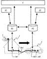
- FIG. 1shows a diagram which illustrates the “Principle of Cascaded Electrical Energy Consumption”, here charging of a vehicle, i.e. a second mobile unit.
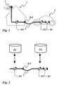
- FIG. 2shows a diagram which illustrates the communication flows between the electronic meters and the backend platforms of the electricity providers.
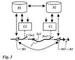
- FIG. 3shows a diagram which illustrates in detail method for transferring energy between a first and a second unit.
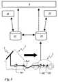
- FIG. 4shows a diagram which illustrates a case where energy provided by public utilities is transferred from a first unit to a second unit which is mobile.
- FIG. 5shows a diagram which illustrates a case where energy is provided and transferred from a first unit to a second unit which is mobile.
- FIG. 6shows a diagram which illustrates a case where energy provided by public utilities is transferred from a second unit to a first unit, whereby the second unit is mobile.
- FIG. 7shows a diagram which illustrates a case where energy provided by public utilities is transferred from a second unit to a first unit, whereby the first and the second units are mobile.
- FIG. 1illustrates the basic principles of cascaded electronic meters, the meters M 1 and M 2 , whereby the corresponding communication is sketched by means of FIG. 2 .
- the present exampleis directed to the charging of a battery B 2 of a vehicle, i.e. a second unit 2 .
- the exchange of communication in all figuresis indicated by thick dashed arrows.
- FIG. 1shows a first unit 1 , which is a house, connected to an external power energy provider 5 , i.e. to its utilities.
- the unit 1comprises a meter M 1 and an arbitrary socket So 1 .
- the second unit 2which is mobile, for instance, a vehicle or car, comprises a second meter M 2 and the battery B 2 .
- the first unit 1 and the second unit 2are connected via a power line 3 .
- the power line 3serves also for short-range communication transmission, e.g. a power line communication.
- “The Vehicle”, i.e. the second unit 2is plugged to the socket So 1 of the first unit 1 , which can be e.g. a private household or a public parking area etc.
- the Vehicleequivalently for the mobile unit 2 .
- the household or parking areai.e. the first unit 1
- a smart meteri.e. the first meter M 1
- the first meter M 1is used for measuring energy exchanged with the power grid of the energy provider 5 , i.e. with external power sources and/or an external power consumer connected with this grid.
- the first unit 1has a subscription at a first backend platform P 1 which is the backend platform of the energy provider 5 .
- control information about availability of certain tariffsis given by means of the backend platform P 1 , e.g. cheap tariffs during night time or as long as solar or wind energy is available.
- the meter M 2is connected in such a way with the battery B 2 of the second unit 2 that this battery can be charged through the meter M 2 only.
- the meter M 2is an electronic smart meter, as described above.
- the second meter M 2measures the energy received from an external power source, e.g. via the socket So 1 .
- the unit 2 and the meter M 2communicate with this backend platform as described above.
- the unit 2has a subscription at another electricity provider's backend platform P 2 and different special tariffs especially for the mobile consumption.
- the first and the second backend platform P 1 , P 2communicate with the first and the second meter M 1 , M 2 , respectively via a public switched telephone network, e.g. a GPRS service of a GSM network or a UMTS network and/or a public land mobile network.
- a public switched telephone networke.g. a GPRS service of a GSM network or a UMTS network and/or a public land mobile network.
- the utility assigned to the second backend platform P 2could be a virtual or a real electricity producing utility, which is specialized on mobile tariffs. This kind of tariffs could even include taxes for vehicle energy consumption similar to today's petroleum tax.
- the given arrangementguarantees that the consumption information is securely transferred to the backend platforms P 1 and P 2 of the corresponding utilities through a Public Key Infrastructure.
- the first unit 1 and the second unit 2comprise a first switch Sw 1 and second switch Sw 2 , respectively, which allow the interruption of the transfer of energy between the first unit 1 and the second unit 2 , respectively.
- both switches Sw 1 and Sw 2do not interrupt communication passing through these switches, i.e. the switches Sw 1 and Sw 2 are able to break the energy flow, i.e. the transfer of energy, while being open for power line communication via the power line 3 so that all necessary communication on authentication, tariffs and control etc. can be carried out before the actual energy flow starts.
- the preconditional power line communicationis allowed through the application of a high pass filter bridging the electrical power switch.
- the switches Sw 1 and Sw 2can be realized by conventional electrical power switches.
- the first unit 1 and the second unit 2comprise a first control box C 1 and a second control box C 2 , respectively.
- the first control box C 1 and the second control box C 2comprise communication means which allow to communicate via the public land mobile network and/or the public telephone switched network used for communication with the platforms P 1 and P 2 . Furthermore the first control box C 1 and the second control box C 2 control the first switch Sw 1 and the second switch Sw 2 , respectively.
- the first control box C 1receives control information from the first backend platform P 1 in case that e.g. cheap night tariffs shall be used.
- the first control box C 1controls the first switch Sw 1 accordingly.
- the second control box C 2 and the second switch Sw 2are controlled e.g. by a bord controller of the second unit 2 , and/or manually and/or by the second backend platform P 2 , e.g. for Pre-paid tariffs or in case that the contract with utilities assigned to the second unit 2 is cancelled or expired.
- a Public Key Infrastructureis used for a secure communication.
- Metering informationis secured by the Public Keys of the first and second backend platforms P 1 , P 2 used for encryption, authenticity of information and authentication of consumers or subscribers.
- Control information sent to the meters M 1 , M 2 and control boxes C 1 , C 2are secured by the public keys of the units 1 and 2 or the public keys of the meters M 1 , M 2 and control boxes C 1 , C 2 , correspondingly.
- the second meter M 2is sending its measured amount of energy consumption on two ways:
- Thisallows a verification of the amount of transferred energy and transferred energy and/or consumption data on both parties sides.
- the communication between “The Vehicle”, i.e. the second unit 2 , and the first backend platform P 1 and control box C 1could be set up through a public land mobile network.
- the first control box C 1forwards the amount of transferred energy, i.e. the consumption, together with total own consumption measured by the first meter M 1 as an additional information on request to the first backend platform P 1 .
- the authenticity of “The Vehicle” consumptioni.e. the amount of transferred energy to the second unit 2 , can be checked and verified.
- the units 1 and 2 and the platforms P 1 and P 2execute, for example, the following procedure for transferring energy from the first unit 1 to the second unit 2 :
- the first unit 1is connected to the second unit 2 by means of a power line 3 , wherein a plug of the power line 3 is inserted into a socket So 1 of the first unit.
- the second control box C 2sends a charge request to the first control box C 1 via the power line 3 , i.e. the second control box C 2 sends, preferably via the power line 3 , a request for transferring energy to the first control box C 1 .
- an authentication procedure between the first and the second unit 1 , 2is executed by means of the first and second platform P 1 , P 2 as follows:
- the second control box C 2sends an authentication request of the second unit 2 , in the present case “The Vehicle”, preferably via the power line 3 , to the first control box C 1 .
- the first control box C 1sends the received authentication request of the second unit 2 to the first backend platform P 1 assigned to the first unit 1 .
- the first backend platform P 1sends the authentication request to the second backend platform P 2 . It is possible that the authentication request further comprises the amount and tariff preference of the requested transfer of energy.
- the second backend platformauthenticates the authentication request of the first backend platform P 1 by providing corresponding credentials.
- the first backend platform P 1forwards the credentials to the first control box C 1 .
- the first control box C 1unbars the first switch Sw 1 , preferably according to the received credentials.
- Public Key encrypted identifications between the first and second control boxes C 1 , C 2are exchanged to clearly identify the transfer of energy involved customers or users.
- the first control box C 1Upon successful execution of the authentication procedure, the first control box C 1 unbars the first switch Sw 1 .
- the second backend platformsends tariff and control data to the second control box C 2 so that the second control box C 2 can control the second switch Sw 2 according to the received tariff and control data.
- the second control box C 2sends during the transfer of energy, preferably in short time intervals, interim data values of the transfer of energy, preferably comprising an amount of transferred energy, timestamps, and/or an identification of the first unit 1 to the first control box C 1 .
- the first control box C 1stores said received interim data values.
- the second control box C 2sends an amount of the transferred energy measured by the second meter M 2 to the first control box C 1 .
- the first meter M 1 and the second meter M 2measure, preferably in short time intervals, energy consumption data comprising an amount of energy consumption, timestamps, and preferably an identification of the first unit 1 and second unit 2 , respectively. Said energy consumption data is forwarded by the corresponding control boxes C 1 and C 2 to the first and second backend platform P 1 , P 2 as further input for the consumption clearing procedure.
- the first control box C 1 and the second control box C 2store data values of the transfer of energy, preferably comprising an amount of transferred energy, timestamps, and/or an identification of the first unit 1 and/or second unit 2 , respectively for later checking of the consumption clearing procedure executed by the first and second backend platform P 1 , P 2 .
- the control boxes C 1 and/or C 2stop the transfer of energy when the request amount of transferred energy is reached and the first and/or second switch Sw 1 , Sw 2 will be barred correspondingly. After the termination of the transfer of energy it is possible to unplug the plug of the power line 3 from the socket So 1 of the first unit 1 .
- the control boxes C 1 and/or C 2obtain the corresponding instruction or information directly by the first and/or second meter M 1 , M 2 , respectively or indirectly via the first and/or second backend platform P 1 , P 2 , respectively.
- energy consumption datacomprising data about the amount of transferred energy measured by the first meter M 1 is sent to the first backend platform P 1
- energy consumption datacomprising data about the amount of transferred energy measured by the second meter M 2 is send to the second backend platform P 2 .
- the consumption clearing procedure between the first and the second unit 1 , 2 by means of the received energy consumption datais executed at the first and second platform P 1 , P 2 , preferably according to corresponding agreements.
- the energy transferred from the first to the second unitis at the one hand subtracted from the energy received by the first unit and counted by the first meter and at the other hand allocated to the energy consumption of the second unit.
- these corrected values of energy consumptionsare used as basis for billing the energy consumption according to the specific tariff of the first and second unit, respectively.
- this datais used to execute a consumption clearing process between the energy providers of the first and second unit.
- FIGS. 4 to 7show further preferred embodiments wherein a further platform 4 for further processing is involved, such as tax calculation.
- a first and a second subscriber 11 , 21 assigned to the first unit 1 and the second unit 2 , respectivelyreceive by means of the first backend platform P 1 and the second backend platform P 2 , respectively, invoices comprising billing according to the corresponding tariffs.
- These invoicescan further comprise a further rate, for instance a tax rate.
- Such a further rateis forwarded by the backend platforms P 1 , P 2 to the further platform 4 .
- the big unidirectional arrowindicates the direction of the energy flow between the first and second unit 1 , 2 , as shown in FIGS. 4 to 7 .
- FIG. 4By means of FIG. 4 the case is illustrated where energy provided by public utilities 5 , i.e. public energy providers, is transferred from a first unit 1 to second unit 2 which is mobile.
- public utilities 5i.e. public energy providers
- the inventionallows to differentiate energy consumption by means of cascaded meters, i.e. the meters M 1 , M 2 , for the utilities' backend platforms P 1 , P 2 .
- the utilities 5carry out a clearing of kilowatt-hours among each other according to their contracts for the exchange of energy by means of the corresponding backend platforms P 1 , P 2 .
- the end consumer 11 , 21is billed according to the tariffs.
- the billingis carried out by each utility's billing system by means of the backend platforms P 1 , P 2 , which can consider also the taxes or other deductions.
- the described inventionallows to verify for which purpose the energy is consumed, this information can be used as basis for tax payments according to the usage of the energy.
- the identification of the purpose of energy consumptioncan be comprised within the energy transfer data available at the backend platforms P 1 , P 2 .
- the energy consumption tax for “The Vehicle”, i.e. the second unit 2can be charged automatically and different from the energy consumption tax in a household or a company, i.e. the first unit.
- FIG. 5By means of FIG. 5 the case is illustrated where energy is provided and transferred from a first unit 1 to second unit 2 which is mobile.
- the first unit 1provides private energy generation 5 , like wind, water and/or solar energy.
- the Vehiclei.e. the second unit 2
- private operated generators 5e.g. solar, wind, water etc.
- the private energy generation utility 5has no assigned backend platform, there will be no request for consumption clearing communicated to the second backend platform P 2 of “The Vehicle”, i.e. the second unit 2 .
- the second platform P 2 of the “The Vehicle” 2will record the consumption of “The Vehicle” and will be able to calculate correct tax rates.
- FIG. 6By means of FIG. 6 the case illustrated where energy provided by public utilities is transferred form a second unit 2 to a first unit 1 , like a household, whereby the second unit 2 is mobile.
- a special tariffcan be defined for this case and the energy consumption tax can be raised or lowered, e.g. as household tax and not as vehicle energy consumption tax, even if the energy was transported by “The Vehicle” to the house.
- FIG. 7shows energy sharing with another mobile user.
- the Vehiclei.e. the second unit 2
- the users 11 and 21 of these vehicles 1 and 2do not have to take care about cost compensation considering any individual tariffs or tax rates.
- This taskis carried out by the corresponding backend platforms P 1 and P 2 , doing the clearing and tax calculation etc. Even if the two mobile parties do not know each other, the transaction appears on each party's invoice with the correct billing and tax rate.
Landscapes
- Engineering & Computer Science (AREA)
- Power Engineering (AREA)
- Transportation (AREA)
- Mechanical Engineering (AREA)
- Business, Economics & Management (AREA)
- General Physics & Mathematics (AREA)
- Physics & Mathematics (AREA)
- Economics (AREA)
- Health & Medical Sciences (AREA)
- General Business, Economics & Management (AREA)
- Primary Health Care (AREA)
- Theoretical Computer Science (AREA)
- Tourism & Hospitality (AREA)
- Strategic Management (AREA)
- General Health & Medical Sciences (AREA)
- Human Resources & Organizations (AREA)
- Marketing (AREA)
- Life Sciences & Earth Sciences (AREA)
- Water Supply & Treatment (AREA)
- Public Health (AREA)
- Sustainable Energy (AREA)
- Sustainable Development (AREA)
- Beverage Vending Machines With Cups, And Gas Or Electricity Vending Machines (AREA)
- Management, Administration, Business Operations System, And Electronic Commerce (AREA)
- Electric Propulsion And Braking For Vehicles (AREA)
- Charge And Discharge Circuits For Batteries Or The Like (AREA)
- Remote Monitoring And Control Of Power-Distribution Networks (AREA)
Abstract
Description
Claims (20)
Priority Applications (1)
| Application Number | Priority Date | Filing Date | Title |
|---|---|---|---|
| US13/604,099US8614624B2 (en) | 2008-03-04 | 2012-09-05 | Method of transferring energy between a first unit and a second unit |
Applications Claiming Priority (3)
| Application Number | Priority Date | Filing Date | Title |
|---|---|---|---|
| EP08290212AEP2099002A1 (en) | 2008-03-04 | 2008-03-04 | Method of transferring energy between a first unit and a second unit |
| EP08290212.3 | 2008-03-04 | ||
| EP08290212 | 2008-03-04 |
Related Child Applications (1)
| Application Number | Title | Priority Date | Filing Date |
|---|---|---|---|
| US13/604,099ContinuationUS8614624B2 (en) | 2008-03-04 | 2012-09-05 | Method of transferring energy between a first unit and a second unit |
Publications (2)
| Publication Number | Publication Date |
|---|---|
| US20090224939A1 US20090224939A1 (en) | 2009-09-10 |
| US8279041B2true US8279041B2 (en) | 2012-10-02 |
Family
ID=39563349
Family Applications (2)
| Application Number | Title | Priority Date | Filing Date |
|---|---|---|---|
| US12/396,687Expired - Fee RelatedUS8279041B2 (en) | 2008-03-04 | 2009-03-03 | Method of transferring energy between a first unit and a second unit |
| US13/604,099ActiveUS8614624B2 (en) | 2008-03-04 | 2012-09-05 | Method of transferring energy between a first unit and a second unit |
Family Applications After (1)
| Application Number | Title | Priority Date | Filing Date |
|---|---|---|---|
| US13/604,099ActiveUS8614624B2 (en) | 2008-03-04 | 2012-09-05 | Method of transferring energy between a first unit and a second unit |
Country Status (6)
| Country | Link |
|---|---|
| US (2) | US8279041B2 (en) |
| EP (1) | EP2099002A1 (en) |
| JP (1) | JP5611058B2 (en) |
| KR (1) | KR101203406B1 (en) |
| CN (1) | CN101527065B (en) |
| WO (1) | WO2009109431A1 (en) |
Cited By (3)
| Publication number | Priority date | Publication date | Assignee | Title |
|---|---|---|---|---|
| US20120086393A1 (en)* | 2010-10-08 | 2012-04-12 | Richard Landry Gray | Device and Method for an Intermittent Load |
| US20120303259A1 (en)* | 2011-05-25 | 2012-11-29 | Green Charge Networks Llc | Providing Roadside Charging Services |
| US11420528B2 (en) | 2015-08-17 | 2022-08-23 | Nokia Technologies Oy | Methods, apparatuses and computer-readable instructions for activating charging of an electric vehicle |
Families Citing this family (34)
| Publication number | Priority date | Publication date | Assignee | Title |
|---|---|---|---|---|
| EP2099002A1 (en)* | 2008-03-04 | 2009-09-09 | Alcatel Lucent | Method of transferring energy between a first unit and a second unit |
| JP4950246B2 (en)* | 2009-04-27 | 2012-06-13 | 三菱電機株式会社 | Vehicle charging system |
| JP2012151519A (en)* | 2009-07-31 | 2012-08-09 | Panasonic Corp | On-vehicle charger and vehicle using it |
| US10787090B2 (en)* | 2009-10-24 | 2020-09-29 | Paul S. Levy | Method and process of administrating recharging of electric vehicles using low cost charge stations |
| US20110099111A1 (en)* | 2009-10-24 | 2011-04-28 | Levy Paul S | Method and Process of billing for goods leveraging a single connection action |
| US9043038B2 (en)* | 2010-02-18 | 2015-05-26 | University Of Delaware | Aggregation server for grid-integrated vehicles |
| US20120044843A1 (en)* | 2010-08-17 | 2012-02-23 | Levy Paul S | Method of interconnecting multiple Electrical Vehicle Slave Charge Stations to a single Master Charge Station using a central hub or daisy chain connection means |
| JP5738103B2 (en)* | 2011-07-11 | 2015-06-17 | 三菱電機株式会社 | Electric vehicle and power management device |
| EP2572922A1 (en) | 2011-09-26 | 2013-03-27 | Alcatel Lucent | Method of charging an energy storage unit |
| JP5218800B2 (en)* | 2011-10-31 | 2013-06-26 | トヨタ自動車株式会社 | VEHICLE HAVING POWER STORAGE UNIT AND CHARGE / DISCHARGE SYSTEM INCLUDING THE VEHICLE AND ENERGY MANAGEMENT |
| JP2013222733A (en)* | 2012-04-13 | 2013-10-28 | Honda Motor Co Ltd | Power generation system |
| FR2990762B1 (en)* | 2012-05-16 | 2015-06-19 | Hager Electro Sas | TAKING INTO ACCOUNT FOR DOWNSTREAM EQUIPMENT IN FOLLOWING ELECTRICAL CONSUMPTION |
| US9463696B2 (en)* | 2012-07-18 | 2016-10-11 | General Electric Company | Systems and methods for mobile power conditioning platform |
| EP2883219A1 (en) | 2012-08-09 | 2015-06-17 | Technische Universität Dortmund | Method for ensuring functional reliability in electromobility by means of digital certificates |
| GB201301582D0 (en)* | 2013-01-29 | 2013-03-13 | Itron Inc | Electricity meter |
| DE102014218061A1 (en)* | 2014-09-10 | 2016-03-10 | Continental Automotive Gmbh | Device for determining the charging energy for a vehicle |
| DE102015101375A1 (en)* | 2015-01-30 | 2016-08-04 | Weiss+Appetito Communication Gmbh | System for the controlled release of electrical energy, gas, water or similar media and method therefor |
| DE102015205740A1 (en)* | 2015-03-31 | 2016-10-06 | Bayerische Motoren Werke Aktiengesellschaft | Method for energy management of a motor vehicle |
| CN107131905B (en)* | 2016-02-26 | 2021-07-27 | 高准公司 | Testing two or more metering assemblies |
| US20200023747A1 (en)* | 2017-02-22 | 2020-01-23 | Iotecha Corp. | Method and Apparatus for Charging a Battery From an Isolatable Electric Power Grid |
| US11465586B1 (en)* | 2017-09-28 | 2022-10-11 | Apple Inc. | User-to-vehicle interaction |
| DE102018131313A1 (en)* | 2018-12-07 | 2020-06-10 | innogy Consulting GmbH | Charging system for charging an energy storage device of an electric vehicle and method for operating a charging system |
| US12046905B2 (en) | 2019-03-28 | 2024-07-23 | Nuvve Corporation | Multi-technology grid regulation service |
| US11685283B2 (en) | 2020-03-17 | 2023-06-27 | Toyota Motor North America, Inc. | Transport-based energy allocation |
| US11571983B2 (en) | 2020-03-17 | 2023-02-07 | Toyota Motor North America, Inc. | Distance-based energy transfer from a transport |
| US11890952B2 (en) | 2020-03-17 | 2024-02-06 | Toyot Motor North America, Inc. | Mobile transport for extracting and depositing energy |
| US11552507B2 (en)* | 2020-03-17 | 2023-01-10 | Toyota Motor North America, Inc. | Wirelessly notifying a transport to provide a portion of energy |
| US11618329B2 (en) | 2020-03-17 | 2023-04-04 | Toyota Motor North America, Inc. | Executing an energy transfer directive for an idle transport |
| US20220383429A1 (en) | 2021-06-01 | 2022-12-01 | Nuvve Corporation | Virtualized battery resources for grid service participation |
| US11695274B1 (en) | 2022-03-21 | 2023-07-04 | Nuvve Corporation | Aggregation platform for intelligent local energy management system |
| US11747781B1 (en) | 2022-03-21 | 2023-09-05 | Nuvve Corporation | Intelligent local energy management system at local mixed power generating sites for providing grid services |
| WO2023208655A1 (en)* | 2022-04-28 | 2023-11-02 | Sew-Eurodrive Gmbh & Co. Kg | Transport system and method for operating a transport system |
| DE102022134414A1 (en) | 2022-12-21 | 2024-06-27 | Bayerische Motoren Werke Aktiengesellschaft | Charging an electric vehicle using a home charger |
| DE102024202813A1 (en) | 2024-03-25 | 2025-09-25 | Siemens Aktiengesellschaft | Consumption measuring device, consumption meter, supply system and method for their operation |
Citations (17)
| Publication number | Priority date | Publication date | Assignee | Title |
|---|---|---|---|---|
| US5306999A (en)* | 1993-01-15 | 1994-04-26 | Hubbell Incorporated | Electric vehicle charging station |
| US5461298A (en)* | 1993-01-15 | 1995-10-24 | Hughes Aircraft Company | Automatic electric vehicle charging system |
| US5462439A (en)* | 1993-04-19 | 1995-10-31 | Keith; Arlie L. | Charging batteries of electric vehicles |
| US5594318A (en)* | 1995-04-10 | 1997-01-14 | Norvik Traction Inc. | Traction battery charging with inductive coupling |
| US5617003A (en)* | 1995-03-24 | 1997-04-01 | Kabushiki Kaisha Toyoda Jidoshokki Seisakusho | Method and apparatus for charging a battery of an electric vehicle |
| US5646500A (en)* | 1995-01-27 | 1997-07-08 | Delco Electronics Corp. | Inductively coupled charger having a light-activated mechanical positioning system |
| GB2313462A (en) | 1996-05-24 | 1997-11-26 | Landis & Gyr Ag | Metering systems |
| US5758414A (en)* | 1994-04-28 | 1998-06-02 | Hubbell Incorporated | Method of making universal electrical connector |
| US5847537A (en)* | 1996-10-19 | 1998-12-08 | Parmley, Sr.; Daniel W. | Electric vehicle charging station system |
| US6459234B2 (en)* | 1999-12-08 | 2002-10-01 | Kabushiki Kaisha Toyoda Jidoshokki Seisakusho | Charger having secured power supplier and cable |
| US6476728B1 (en) | 1998-11-16 | 2002-11-05 | Canon Kabushiki Kaisha | Power consumption management apparatus and method |
| DE10304284A1 (en) | 2003-02-03 | 2004-08-19 | Siemens Ag | Identification arrangement for controlling access of electric vehicles to charging stations, wherein an onboard vehicle identification unit is wirelessly connected to the charging station to permit authentication |
| US20060042846A1 (en)* | 2004-08-24 | 2006-03-02 | Honeywell International | Electrical energy management system on a more electric vehicle |
| GB2438979A (en) | 2006-06-08 | 2007-12-12 | Elektromotive Ltd | Charging station for electric vehicle |
| WO2009090813A1 (en) | 2008-01-15 | 2009-07-23 | Toyota Jidosha Kabushiki Kaisha | Charging system for electric vehicle |
| US20110140658A1 (en)* | 2009-12-15 | 2011-06-16 | Liberty Plugins, Inc. | Automated Parking Garage with Electric Vehicle Charging |
| US7999506B1 (en)* | 2008-04-09 | 2011-08-16 | SeventhDigit Corporation | System to automatically recharge vehicles with batteries |
Family Cites Families (16)
| Publication number | Priority date | Publication date | Assignee | Title |
|---|---|---|---|---|
| US4777354A (en)* | 1986-01-27 | 1988-10-11 | Barry Thomas | System for controlling the supply of utility services to consumers |
| SE503254C2 (en)* | 1994-07-04 | 1996-04-29 | Vattenfall Ab | Electricity distribution network, method and apparatus for regulating electrical current from the grid |
| JP3985390B2 (en)* | 1999-06-17 | 2007-10-03 | 日産自動車株式会社 | Power management system |
| JP4426504B2 (en) | 2005-06-22 | 2010-03-03 | 株式会社日立製作所 | Secondary battery supply control device and power supply system for hybrid electric vehicle |
| JP2007066278A (en)* | 2005-08-30 | 2007-03-15 | Yoshito Matsuo | Power supply system to storage battery-driven electric vehicle or like |
| JP4929672B2 (en)* | 2005-10-20 | 2012-05-09 | 東京電力株式会社 | Power supply system for vehicles |
| US7518489B2 (en)* | 2006-01-19 | 2009-04-14 | Honda Motor Co., Ltd. | Method and system for remote immobilization of vehicles |
| JP4353197B2 (en)* | 2006-03-13 | 2009-10-28 | トヨタ自動車株式会社 | Vehicles and electrical equipment |
| JP4781136B2 (en)* | 2006-03-16 | 2011-09-28 | 中国電力株式会社 | Power supply system and power supply method |
| US7693609B2 (en)* | 2007-09-05 | 2010-04-06 | Consolidated Edison Company Of New York, Inc. | Hybrid vehicle recharging system and method of operation |
| JPWO2009075313A1 (en)* | 2007-12-13 | 2011-04-28 | トヨタ自動車株式会社 | Electricity amount calculation device, fee calculation device and fee calculation method for calculating fee for power consumption, vehicle information output device and information output method |
| JP5152644B2 (en)* | 2008-01-25 | 2013-02-27 | 九州電力株式会社 | Electric drive charging system and method |
| EP2099002A1 (en)* | 2008-03-04 | 2009-09-09 | Alcatel Lucent | Method of transferring energy between a first unit and a second unit |
| JP2010179694A (en)* | 2009-02-03 | 2010-08-19 | Denso Corp | Plug-in vehicle management system |
| US20110200193A1 (en)* | 2010-02-12 | 2011-08-18 | Daniel Ray Blitz | Method and apparatus for controlling the recharging of electric vehicles and detecting stolen vehicles and vehicular components |
| US20110227531A1 (en)* | 2010-03-21 | 2011-09-22 | Joseph Rajakaruna | Systems and methods for recharging an electric vehicle |
- 2008
- 2008-03-04EPEP08290212Apatent/EP2099002A1/ennot_activeCeased
- 2009
- 2009-01-29KRKR1020107019605Apatent/KR101203406B1/ennot_activeExpired - Fee Related
- 2009-01-29JPJP2010549068Apatent/JP5611058B2/ennot_activeExpired - Fee Related
- 2009-01-29WOPCT/EP2009/051012patent/WO2009109431A1/enactiveApplication Filing
- 2009-03-02CNCN2009100077943Apatent/CN101527065B/enactiveActive
- 2009-03-03USUS12/396,687patent/US8279041B2/ennot_activeExpired - Fee Related
- 2012
- 2012-09-05USUS13/604,099patent/US8614624B2/enactiveActive
Patent Citations (18)
| Publication number | Priority date | Publication date | Assignee | Title |
|---|---|---|---|---|
| US5306999A (en)* | 1993-01-15 | 1994-04-26 | Hubbell Incorporated | Electric vehicle charging station |
| US5461298A (en)* | 1993-01-15 | 1995-10-24 | Hughes Aircraft Company | Automatic electric vehicle charging system |
| US5462439A (en)* | 1993-04-19 | 1995-10-31 | Keith; Arlie L. | Charging batteries of electric vehicles |
| US5758414A (en)* | 1994-04-28 | 1998-06-02 | Hubbell Incorporated | Method of making universal electrical connector |
| US5646500A (en)* | 1995-01-27 | 1997-07-08 | Delco Electronics Corp. | Inductively coupled charger having a light-activated mechanical positioning system |
| US5617003A (en)* | 1995-03-24 | 1997-04-01 | Kabushiki Kaisha Toyoda Jidoshokki Seisakusho | Method and apparatus for charging a battery of an electric vehicle |
| US5594318A (en)* | 1995-04-10 | 1997-01-14 | Norvik Traction Inc. | Traction battery charging with inductive coupling |
| GB2313462A (en) | 1996-05-24 | 1997-11-26 | Landis & Gyr Ag | Metering systems |
| US5847537A (en)* | 1996-10-19 | 1998-12-08 | Parmley, Sr.; Daniel W. | Electric vehicle charging station system |
| US6476728B1 (en) | 1998-11-16 | 2002-11-05 | Canon Kabushiki Kaisha | Power consumption management apparatus and method |
| US6459234B2 (en)* | 1999-12-08 | 2002-10-01 | Kabushiki Kaisha Toyoda Jidoshokki Seisakusho | Charger having secured power supplier and cable |
| DE10304284A1 (en) | 2003-02-03 | 2004-08-19 | Siemens Ag | Identification arrangement for controlling access of electric vehicles to charging stations, wherein an onboard vehicle identification unit is wirelessly connected to the charging station to permit authentication |
| US20060042846A1 (en)* | 2004-08-24 | 2006-03-02 | Honeywell International | Electrical energy management system on a more electric vehicle |
| GB2438979A (en) | 2006-06-08 | 2007-12-12 | Elektromotive Ltd | Charging station for electric vehicle |
| WO2009090813A1 (en) | 2008-01-15 | 2009-07-23 | Toyota Jidosha Kabushiki Kaisha | Charging system for electric vehicle |
| US20110022222A1 (en)* | 2008-01-15 | 2011-01-27 | Toyota Jidosha Kabushiki Kaisha | Charging system of electric powered vehicle |
| US7999506B1 (en)* | 2008-04-09 | 2011-08-16 | SeventhDigit Corporation | System to automatically recharge vehicles with batteries |
| US20110140658A1 (en)* | 2009-12-15 | 2011-06-16 | Liberty Plugins, Inc. | Automated Parking Garage with Electric Vehicle Charging |
Non-Patent Citations (2)
| Title |
|---|
| "La Voiture Urbaine Electrique Par Abonnement," Opeugeot Lance Le Systeme Tulip, Revue Automobile, Buechler Grafino AG, Berne, CH, vol. 90, No. 16, XP000497754, pp. 23-24, Apr. 13, 2005. |
| European Search Report, Jul. 7, 2008. |
Cited By (5)
| Publication number | Priority date | Publication date | Assignee | Title |
|---|---|---|---|---|
| US20120086393A1 (en)* | 2010-10-08 | 2012-04-12 | Richard Landry Gray | Device and Method for an Intermittent Load |
| US20120303259A1 (en)* | 2011-05-25 | 2012-11-29 | Green Charge Networks Llc | Providing Roadside Charging Services |
| US8963481B2 (en) | 2011-05-25 | 2015-02-24 | Green Charge Networks | Charging service vehicles and methods using modular batteries |
| US9007020B2 (en) | 2011-05-25 | 2015-04-14 | Green Charge Networks | Charging service vehicles with battery and generator sources |
| US11420528B2 (en) | 2015-08-17 | 2022-08-23 | Nokia Technologies Oy | Methods, apparatuses and computer-readable instructions for activating charging of an electric vehicle |
Also Published As
| Publication number | Publication date |
|---|---|
| JP5611058B2 (en) | 2014-10-22 |
| CN101527065B (en) | 2011-07-27 |
| US20120326838A1 (en) | 2012-12-27 |
| US20090224939A1 (en) | 2009-09-10 |
| US8614624B2 (en) | 2013-12-24 |
| JP2011520163A (en) | 2011-07-14 |
| CN101527065A (en) | 2009-09-09 |
| KR101203406B1 (en) | 2012-11-21 |
| KR20100106620A (en) | 2010-10-01 |
| EP2099002A1 (en) | 2009-09-09 |
| WO2009109431A1 (en) | 2009-09-11 |
Similar Documents
| Publication | Publication Date | Title |
|---|---|---|
| US8279041B2 (en) | Method of transferring energy between a first unit and a second unit | |
| US11151552B2 (en) | Method and system of billing for charging a vehicle battery leveraging a single connection action | |
| US8143842B2 (en) | Dynamic load management for use in recharging vehicles equipped with electrically powered propulsion systems | |
| US8258743B2 (en) | Sub-network load management for use in recharging vehicles equipped with electrically powered propulsion systems | |
| CN102742113B (en) | electric vehicle charging and charging | |
| US8198859B2 (en) | Intra-vehicle charging system for use in recharging vehicles equipped with electrically powered propulsion systems | |
| US8305032B2 (en) | Centralized load management for use in controllably recharging vehicles equipped with electrically powered propulsion systems | |
| US20100145837A1 (en) | Network for authentication, authorization, and accounting of recharging processes for vehicles equipped with electrically powered propulsion systems | |
| US20100145885A1 (en) | System for on-board metering of recharging energy consumption in vehicles equipped with electrically powered propulsion systems | |
| Falk et al. | Electric vehicle charging infrastructure security considerations and approaches | |
| US20100141203A1 (en) | Self-identifying power source for use in recharging vehicles equipped with electrically powered propulsion systems | |
| WO2011044543A2 (en) | Method and process of administrating electric vehicle charge stations and billing for the recharging of electric vehicles leveraging a single connection action using low cost charge stations | |
| US20100094737A1 (en) | Utility communications design concept | |
| WO2013073625A1 (en) | Billing system and electric vehicle charging system | |
| US20210295615A1 (en) | Electric vehicle energy balance crediting and debiting system and a method thereof | |
| Falk et al. | Securely connecting electric vehicles to the smart grid | |
| JP2016025682A (en) | Electric transfer suppression system | |
| WO2011021973A1 (en) | Method of electrical charging | |
| KR102362372B1 (en) | Apparatus for calculating charging charges for electric vehicle using advanced metering infrastructure | |
| KR20240176433A (en) | Communication method for value added service based on supported providers list and apparatus using same | |
| JP2021197762A (en) | In-vehicle device |
Legal Events
| Date | Code | Title | Description |
|---|---|---|---|
| AS | Assignment | Owner name:ALCATEL LUCENT, FRANCE Free format text:ASSIGNMENT OF ASSIGNORS INTEREST;ASSIGNORS:STOCKER, KLAUS;KOPP, DIETER;REEL/FRAME:022336/0774 Effective date:20081024 | |
| FEPP | Fee payment procedure | Free format text:PAYOR NUMBER ASSIGNED (ORIGINAL EVENT CODE: ASPN); ENTITY STATUS OF PATENT OWNER: LARGE ENTITY | |
| STCF | Information on status: patent grant | Free format text:PATENTED CASE | |
| AS | Assignment | Owner name:CREDIT SUISSE AG, NEW YORK Free format text:SECURITY AGREEMENT;ASSIGNOR:LUCENT, ALCATEL;REEL/FRAME:029821/0001 Effective date:20130130 Owner name:CREDIT SUISSE AG, NEW YORK Free format text:SECURITY AGREEMENT;ASSIGNOR:ALCATEL LUCENT;REEL/FRAME:029821/0001 Effective date:20130130 | |
| AS | Assignment | Owner name:ALCATEL LUCENT, FRANCE Free format text:RELEASE BY SECURED PARTY;ASSIGNOR:CREDIT SUISSE AG;REEL/FRAME:033868/0001 Effective date:20140819 | |
| FPAY | Fee payment | Year of fee payment:4 | |
| FEPP | Fee payment procedure | Free format text:MAINTENANCE FEE REMINDER MAILED (ORIGINAL EVENT CODE: REM.); ENTITY STATUS OF PATENT OWNER: LARGE ENTITY | |
| LAPS | Lapse for failure to pay maintenance fees | Free format text:PATENT EXPIRED FOR FAILURE TO PAY MAINTENANCE FEES (ORIGINAL EVENT CODE: EXP.); ENTITY STATUS OF PATENT OWNER: LARGE ENTITY | |
| STCH | Information on status: patent discontinuation | Free format text:PATENT EXPIRED DUE TO NONPAYMENT OF MAINTENANCE FEES UNDER 37 CFR 1.362 | |
| FP | Lapsed due to failure to pay maintenance fee | Effective date:20201002 |