US8278870B2 - Battery pack authentication for a mobile communication device - Google Patents
Battery pack authentication for a mobile communication deviceDownload PDFInfo
- Publication number
- US8278870B2 US8278870B2US12/709,783US70978310AUS8278870B2US 8278870 B2US8278870 B2US 8278870B2US 70978310 AUS70978310 AUS 70978310AUS 8278870 B2US8278870 B2US 8278870B2
- Authority
- US
- United States
- Prior art keywords
- battery
- main processor
- smart battery
- processor
- smart
- Prior art date
- Legal status (The legal status is an assumption and is not a legal conclusion. Google has not performed a legal analysis and makes no representation as to the accuracy of the status listed.)
- Active
Links
Images


Classifications
- H—ELECTRICITY
- H04—ELECTRIC COMMUNICATION TECHNIQUE
- H04L—TRANSMISSION OF DIGITAL INFORMATION, e.g. TELEGRAPHIC COMMUNICATION
- H04L9/00—Cryptographic mechanisms or cryptographic arrangements for secret or secure communications; Network security protocols
- H04L9/32—Cryptographic mechanisms or cryptographic arrangements for secret or secure communications; Network security protocols including means for verifying the identity or authority of a user of the system or for message authentication, e.g. authorization, entity authentication, data integrity or data verification, non-repudiation, key authentication or verification of credentials
- H04L9/3271—Cryptographic mechanisms or cryptographic arrangements for secret or secure communications; Network security protocols including means for verifying the identity or authority of a user of the system or for message authentication, e.g. authorization, entity authentication, data integrity or data verification, non-repudiation, key authentication or verification of credentials using challenge-response
- G—PHYSICS
- G06—COMPUTING OR CALCULATING; COUNTING
- G06F—ELECTRIC DIGITAL DATA PROCESSING
- G06F1/00—Details not covered by groups G06F3/00 - G06F13/00 and G06F21/00
- G06F1/26—Power supply means, e.g. regulation thereof
- G06F1/28—Supervision thereof, e.g. detecting power-supply failure by out of limits supervision
- G—PHYSICS
- G06—COMPUTING OR CALCULATING; COUNTING
- G06F—ELECTRIC DIGITAL DATA PROCESSING
- G06F21/00—Security arrangements for protecting computers, components thereof, programs or data against unauthorised activity
- G06F21/30—Authentication, i.e. establishing the identity or authorisation of security principals
- G06F21/31—User authentication
- H—ELECTRICITY
- H01—ELECTRIC ELEMENTS
- H01M—PROCESSES OR MEANS, e.g. BATTERIES, FOR THE DIRECT CONVERSION OF CHEMICAL ENERGY INTO ELECTRICAL ENERGY
- H01M10/00—Secondary cells; Manufacture thereof
- H01M10/42—Methods or arrangements for servicing or maintenance of secondary cells or secondary half-cells
- H01M10/425—Structural combination with electronic components, e.g. electronic circuits integrated to the outside of the casing
- H01M10/4257—Smart batteries, e.g. electronic circuits inside the housing of the cells or batteries
- H—ELECTRICITY
- H01—ELECTRIC ELEMENTS
- H01M—PROCESSES OR MEANS, e.g. BATTERIES, FOR THE DIRECT CONVERSION OF CHEMICAL ENERGY INTO ELECTRICAL ENERGY
- H01M50/00—Constructional details or processes of manufacture of the non-active parts of electrochemical cells other than fuel cells, e.g. hybrid cells
- H01M50/20—Mountings; Secondary casings or frames; Racks, modules or packs; Suspension devices; Shock absorbers; Transport or carrying devices; Holders
- H01M50/202—Casings or frames around the primary casing of a single cell or a single battery
- H—ELECTRICITY
- H01—ELECTRIC ELEMENTS
- H01M—PROCESSES OR MEANS, e.g. BATTERIES, FOR THE DIRECT CONVERSION OF CHEMICAL ENERGY INTO ELECTRICAL ENERGY
- H01M50/00—Constructional details or processes of manufacture of the non-active parts of electrochemical cells other than fuel cells, e.g. hybrid cells
- H01M50/20—Mountings; Secondary casings or frames; Racks, modules or packs; Suspension devices; Shock absorbers; Transport or carrying devices; Holders
- H01M50/247—Mountings; Secondary casings or frames; Racks, modules or packs; Suspension devices; Shock absorbers; Transport or carrying devices; Holders specially adapted for portable devices, e.g. mobile phones, computers, hand tools or pacemakers
- H—ELECTRICITY
- H02—GENERATION; CONVERSION OR DISTRIBUTION OF ELECTRIC POWER
- H02J—CIRCUIT ARRANGEMENTS OR SYSTEMS FOR SUPPLYING OR DISTRIBUTING ELECTRIC POWER; SYSTEMS FOR STORING ELECTRIC ENERGY
- H02J7/00—Circuit arrangements for charging or depolarising batteries or for supplying loads from batteries
- H02J7/00032—Circuit arrangements for charging or depolarising batteries or for supplying loads from batteries characterised by data exchange
- H02J7/00036—Charger exchanging data with battery
- H—ELECTRICITY
- H02—GENERATION; CONVERSION OR DISTRIBUTION OF ELECTRIC POWER
- H02J—CIRCUIT ARRANGEMENTS OR SYSTEMS FOR SUPPLYING OR DISTRIBUTING ELECTRIC POWER; SYSTEMS FOR STORING ELECTRIC ENERGY
- H02J7/00—Circuit arrangements for charging or depolarising batteries or for supplying loads from batteries
- H02J7/00047—Circuit arrangements for charging or depolarising batteries or for supplying loads from batteries with provisions for charging different types of batteries
- H—ELECTRICITY
- H04—ELECTRIC COMMUNICATION TECHNIQUE
- H04L—TRANSMISSION OF DIGITAL INFORMATION, e.g. TELEGRAPHIC COMMUNICATION
- H04L9/00—Cryptographic mechanisms or cryptographic arrangements for secret or secure communications; Network security protocols
- H04L9/32—Cryptographic mechanisms or cryptographic arrangements for secret or secure communications; Network security protocols including means for verifying the identity or authority of a user of the system or for message authentication, e.g. authorization, entity authentication, data integrity or data verification, non-repudiation, key authentication or verification of credentials
- H—ELECTRICITY
- H04—ELECTRIC COMMUNICATION TECHNIQUE
- H04M—TELEPHONIC COMMUNICATION
- H04M1/00—Substation equipment, e.g. for use by subscribers
- H04M1/02—Constructional features of telephone sets
- H04M1/0202—Portable telephone sets, e.g. cordless phones, mobile phones or bar type handsets
- H04M1/026—Details of the structure or mounting of specific components
- H04M1/0262—Details of the structure or mounting of specific components for a battery compartment
- H—ELECTRICITY
- H04—ELECTRIC COMMUNICATION TECHNIQUE
- H04W—WIRELESS COMMUNICATION NETWORKS
- H04W12/00—Security arrangements; Authentication; Protecting privacy or anonymity
- H04W12/06—Authentication
- H—ELECTRICITY
- H04—ELECTRIC COMMUNICATION TECHNIQUE
- H04W—WIRELESS COMMUNICATION NETWORKS
- H04W88/00—Devices specially adapted for wireless communication networks, e.g. terminals, base stations or access point devices
- H04W88/02—Terminal devices
- G—PHYSICS
- G06—COMPUTING OR CALCULATING; COUNTING
- G06F—ELECTRIC DIGITAL DATA PROCESSING
- G06F2221/00—Indexing scheme relating to security arrangements for protecting computers, components thereof, programs or data against unauthorised activity
- G06F2221/21—Indexing scheme relating to G06F21/00 and subgroups addressing additional information or applications relating to security arrangements for protecting computers, components thereof, programs or data against unauthorised activity
- G06F2221/2103—Challenge-response
- G—PHYSICS
- G06—COMPUTING OR CALCULATING; COUNTING
- G06F—ELECTRIC DIGITAL DATA PROCESSING
- G06F2221/00—Indexing scheme relating to security arrangements for protecting computers, components thereof, programs or data against unauthorised activity
- G06F2221/21—Indexing scheme relating to G06F21/00 and subgroups addressing additional information or applications relating to security arrangements for protecting computers, components thereof, programs or data against unauthorised activity
- G06F2221/2129—Authenticate client device independently of the user
- H—ELECTRICITY
- H02—GENERATION; CONVERSION OR DISTRIBUTION OF ELECTRIC POWER
- H02J—CIRCUIT ARRANGEMENTS OR SYSTEMS FOR SUPPLYING OR DISTRIBUTING ELECTRIC POWER; SYSTEMS FOR STORING ELECTRIC ENERGY
- H02J7/00—Circuit arrangements for charging or depolarising batteries or for supplying loads from batteries
- H02J7/00032—Circuit arrangements for charging or depolarising batteries or for supplying loads from batteries characterised by data exchange
- H02J7/00045—Authentication, i.e. circuits for checking compatibility between one component, e.g. a battery or a battery charger, and another component, e.g. a power source
- H—ELECTRICITY
- H04—ELECTRIC COMMUNICATION TECHNIQUE
- H04L—TRANSMISSION OF DIGITAL INFORMATION, e.g. TELEGRAPHIC COMMUNICATION
- H04L2209/00—Additional information or applications relating to cryptographic mechanisms or cryptographic arrangements for secret or secure communication H04L9/00
- H04L2209/80—Wireless
- H—ELECTRICITY
- H04—ELECTRIC COMMUNICATION TECHNIQUE
- H04M—TELEPHONIC COMMUNICATION
- H04M1/00—Substation equipment, e.g. for use by subscribers
- H04M1/66—Substation equipment, e.g. for use by subscribers with means for preventing unauthorised or fraudulent calling
- Y—GENERAL TAGGING OF NEW TECHNOLOGICAL DEVELOPMENTS; GENERAL TAGGING OF CROSS-SECTIONAL TECHNOLOGIES SPANNING OVER SEVERAL SECTIONS OF THE IPC; TECHNICAL SUBJECTS COVERED BY FORMER USPC CROSS-REFERENCE ART COLLECTIONS [XRACs] AND DIGESTS
- Y02—TECHNOLOGIES OR APPLICATIONS FOR MITIGATION OR ADAPTATION AGAINST CLIMATE CHANGE
- Y02E—REDUCTION OF GREENHOUSE GAS [GHG] EMISSIONS, RELATED TO ENERGY GENERATION, TRANSMISSION OR DISTRIBUTION
- Y02E60/00—Enabling technologies; Technologies with a potential or indirect contribution to GHG emissions mitigation
- Y02E60/10—Energy storage using batteries
Definitions
- the embodiments described hereinrelate to a mobile device having a smart battery.
- Peripheral devicessuch as mobile wireless devices or personal data assistants
- the internal battery packis an assembly of one or more batteries and provides a certain charge capacity. Different battery packs have different charge capacities, different termination voltages such as 4.2 V and 4.4 V, for example, as well as different charging/discharging characteristics.
- a battery packhas a battery ID resistor that indicates the battery type from which the charge capacity of the battery pack can be ascertained.
- the charge capacity and the battery typeare important for several reasons. For instance, if the battery is rechargeable, it is important to charge the battery to the proper charge capacity and at the proper rate. If the battery is overcharged, the battery and the mobile device in which it is used can both become damaged. This situation is becoming increasingly more likely due to the increased number of counterfeit batteries that are on the market. For battery packs with battery ID resistors, it is simple to read the resistance value of the battery ID resistor and manufacture a counterfeit battery pack with another resistor that has the same resistance value.
- counterfeit batteriesas well as some third party non-authorized batteries, generally do not have the charge capacity of an authentic battery, may not have the required safety protection circuitry, and may not be compatible with the charging method being employed by the mobile device and therefore could possibly suffer catastrophic failure during charging, or through normal usage.
- One way to deal with counterfeit battery packsmay be to use “smart batteries” which include an embedded microprocessor that can be used to provide security capabilities.
- the mobile wireless deviceusually maintains information for the different battery packs that can be used.
- the mobile wireless devicecan maintain information on the charging/discharging characteristics of various battery packs.
- This informationmay be in the form of a look-up table (LUT) that provides charge capacity versus voltage information.
- LUTlook-up table
- the information in the LUTcan be used by the mobile wireless device to calculate and display battery charge capacity information to a user of the mobile wireless device.
- the battery monitoring software that ships with the mobile wireless deviceneeds to be able to differentiate between different battery packs, so that the battery pack can be charged according to the maximum charge rate, as well as use battery curves that are specific to the type of battery pack. This is necessary so that the battery that ships with the device can be changed, and so that a user can change their battery in the future without incurring any problems.
- the data updatingcan be done through a software upgrade, but users find it inconvenient to update their mobile wireless device.
- FIG. 1is a block diagram of an exemplary embodiment of a mobile communication device
- FIG. 2is a block diagram of an exemplary embodiment of a communication subsystem component of the mobile communication device of FIG. 1 ;
- FIG. 3is a block diagram of an exemplary embodiment of a node of a wireless network that the mobile communication device of FIG. 1 may communicate with;
- FIG. 4is a block diagram of an exemplary embodiment of a generic smart battery that can be used in the mobile communications device of FIG. 1 ;
- FIG. 5Ais a schematic of an exemplary embodiment of a portion of a battery interface that can be used in the mobile communication device of FIG. 1 to couple the main processor to the smart battery;
- FIG. 5Bis a schematic of another exemplary embodiment of a portion of a battery interface that can be used in the mobile communication device of FIG. 1 to couple the main processor to the smart battery;
- FIG. 5Cis a schematic of a portion of another exemplary embodiment of a smart battery
- FIG. 6Ais a block diagram of an exemplary embodiment of a general structure for a packet that can be used for communication between the main processor and the battery processor of the mobile communications device of FIG. 1 ;
- FIG. 6Bis a block diagram of an exemplary embodiment of a packet that can be used for a protocol version request or a battery information request;
- FIG. 6Cis a block diagram of an exemplary embodiment of a protocol version response packet
- FIG. 6Dis a block diagram of an exemplary embodiment of a packet that can be used for a battery authentication challenge, a battery authentication response or a battery information response;
- FIG. 7Ais a block diagram of an exemplary embodiment of a battery information data construct
- FIG. 7Bis a block diagram of an exemplary embodiment of a battery charge/discharge data construct
- FIG. 8is a flowchart of an exemplary embodiment of an authentication process employed by the main processor of the mobile communications device of FIG. 1 to authenticate the smart battery;
- FIG. 9is a flowchart showing the typical operation of the mobile communications device having a smart battery that may or may not be authentic.
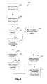
- FIG. 10is a flowchart of an exemplary manufacturing process for manufacturing a mobile communication device having a smart battery.
- battery packrefers to a battery pack having one or more batteries or cells.
- the embodiments described hereingenerally have applicability in the field of data communication for mobile communication devices that use a “smart battery” which is a battery that includes a battery processor and other related circuitry to allow the smart battery to communicate with the mobile device.
- a “smart battery”which is a battery that includes a battery processor and other related circuitry to allow the smart battery to communicate with the mobile device.
- Various types of informationcan be communicated between the battery processor and the processor of the mobile device.
- the embodiments provided hereinwill be described in terms of a mobile wireless communication device that has a main processor, a battery interface and a smart battery having a battery processor and related electronics as will be described in more detail.
- the structure and functionality of the embodiments described hereincan also be applied to a battery charger that charges a smart battery.
- the embodimentsgenerally make use of a mobile communication device, hereafter referred to as a mobile device, that is a two-way communication device with advanced data communication capabilities having the capability to communicate in a wireless or wired fashion with other computing devices including other mobile communication devices.
- the mobile devicecan communicate with other devices through a network of transceiver stations.
- the mobile devicemay also include the capability for voice communications.
- itmay be referred to as a data messaging device, a cellular telephone with data messaging capabilities, a wireless organizer, a wireless Internet appliance, a personal digital assistant, a smart phone, a handheld wireless communication device (with or without telephony capabilities), a wirelessly enabled notebook computer and the like.
- the mobile device 100comprises a number of components, the controlling component being a main processor 102 which controls the overall operation of mobile device 100 .
- Communication functions, including data and voice communications,are performed through a communication subsystem 104 .
- the communication subsystem 104receives messages from and sends messages to a wireless network 200 .
- the communication subsystem 104is configured in accordance with the Global System for Mobile Communication (GSM) and General Packet Radio Services (GPRS) standards.
- GSMGlobal System for Mobile Communication
- GPRSGeneral Packet Radio Services
- the wireless link connecting the communication subsystem 104 with the wireless network 200represents one or more different Radio Frequency (RF) channels, operating according to defined protocols specified for GSM/GPRS communications. With newer network protocols, these channels are capable of supporting both circuit switched voice communications and packet switched data communications.
- RFRadio Frequency
- wireless network 200 associated with the mobile device 100is a GSM/GPRS wireless network in some implementations
- other wireless networkscan also be associated with the mobile device 100 in other implementations.
- the different types of wireless networks that can be employedinclude, for example, data-centric wireless networks, voice-centric wireless networks, and dual-mode networks that can support both voice and data communications over the same physical base stations.
- Combined dual-mode networksinclude, but are not limited to, Code Division Multiple Access (CDMA) or CDMA2000 networks, iDEN networks, GSM/GPRS networks (as mentioned above), and future third-generation (3G) networks like EDGE and UMTS.
- Some other examples of data-centric networksinclude WiFi 802.11, MobitexTM and DataTACTM network communication systems.
- Examples of other voice-centric data networksinclude Personal Communication Systems (PCS) networks like GSM and Time Division Multiple Access (TDMA) systems.
- PCSPersonal Communication Systems
- TDMATime Division Multiple Access
- the main processor 102also interacts with additional subsystems such as a Random Access Memory (RAM) 106 , a device memory 108 , a display 110 , an auxiliary input/output (I/O) subsystem 112 , a data port 114 , a keyboard 116 , a speaker 118 , a microphone 120 , short-range communications subsystem 122 , and other device subsystems 124 .
- RAMRandom Access Memory
- I/Oauxiliary input/output subsystem
- data port 114a keyboard 116
- speaker 118a speaker 118
- microphone 120short-range communications subsystem 122
- short-range communications subsystem 122short-range communications subsystem 122
- the display 110 and the keyboard 116can be used for both communication-related functions, such as entering a text message for transmission over the network 200 , and device-resident functions such as a calculator or task list.
- Operating system software used by the main processor 102is typically stored in a persistent store such as the device memory 108 , which can alternatively be a read-only memory (ROM) or similar storage element (not shown).
- the device memory 108can be flash memory.
- the mobile device 100can send and receive communication signals over the wireless network 200 after required network registration or activation procedures have been completed.
- Network accessis associated with a subscriber or user of the mobile device 100 .
- the mobile device 100may require a SIM/RUIM card 126 (i.e. Subscriber Identity Module or a Removable User Identity Module) to be inserted into a SIM/RUIM interface 128 in order to communicate with a network.
- SIM/RUIM card 126i.e. Subscriber Identity Module or a Removable User Identity Module
- the SIM/RUIM interface 128are entirely optional.
- the SIM card or RUIM 126is one type of a conventional “smart card” that can be used to identify a subscriber of the mobile device 100 and to personalize the mobile device 100 , among other things. Without the SIM card 126 , the mobile device 100 is not fully operational for communication with the wireless network 200 . By inserting the SIM card/RUIM 126 into the SIM/RUIM interface 128 , a subscriber can access all subscribed services. Services can include: web browsing and messaging such as e-mail, voice mail, Short Message Service (SMS), and Multimedia Messaging Services (MMS). More advanced services can include: point of sale, field service and sales force automation.
- the SIM card/RUIM 126includes a processor and memory for storing information.
- the SIM card/RUIM 126is inserted into the SIM/RUIM interface 128 , it is coupled to the main processor 102 .
- the SIM card/RUIM 126contains some user parameters such as an International Mobile Subscriber Identity (IMSI).
- IMSIInternational Mobile Subscriber Identity
- An advantage of using the SIM card/RUIM 126is that a subscriber is not necessarily bound by any single physical mobile device.
- the SIM card/RUIM 126may store additional subscriber information for a mobile device as well, including datebook (or calendar) information and recent call information. Alternatively, user identification information can also be programmed into the device memory 108 .
- the mobile device 100is a battery-powered device and can include a battery interface 132 for interfacing with a smart battery 130 .
- the battery interface 132is also coupled to a power management module 134 , which assists the battery 130 in providing power to the mobile device 100 .
- the main processor 102can also be coupled to the power management module 134 for sharing information.
- the battery interface 132can be provided by the smart battery 130 ; both of these components are described in further detail below.
- the main processor 102in addition to its operating system functions, enables execution of software applications 136 on the mobile device 100 .
- the subset of software applications 136 that control basic device operations, including data and voice communication applications,will normally be installed on the mobile device 100 during its manufacture.
- the software applications 136can include an email program, a web browser, an attachment viewer, and the like.
- the mobile device 100further includes a device state module 138 , an address book 140 , a Personal Information Manager (PIM) 142 , and other modules 144 .
- the device state module 138can provide persistence, i.e. the device state module 138 ensures that important device data is stored in persistent memory, such as the device memory 108 , so that the data is not lost when the mobile device 100 is turned off or loses power.
- the address book 140can provide information for a list of contacts for the user. For a given contact in the address book, the information can include the name, phone number, work address and email address of the contact, among other information.
- the other modules 144can include a configuration module (not shown) as well as other modules that can be used in conjunction with the SIM/RUIM interface 128 .
- the PIM 142has functionality for organizing and managing data items of interest to a subscriber, such as, but not limited to, e-mail, calendar events, voice mails, appointments, and task items.
- a PIM applicationhas the ability to send and receive data items via the wireless network 200 .
- PIM data itemsmay be seamlessly integrated, synchronized, and updated via the wireless network 200 with the mobile device subscriber's corresponding data items stored and/or associated with a host computer system. This functionality creates a mirrored host computer on the mobile device 100 with respect to such items. This can be particularly advantageous when the host computer system is the mobile device subscriber's office computer system.
- Additional applicationscan also be loaded onto the mobile device 100 through at least one of the wireless network 200 , the auxiliary I/O subsystem 112 , the data port 114 , the short-range communications subsystem 122 , or any other suitable device subsystem 124 .
- This flexibility in application installationincreases the functionality of the mobile device 100 and can provide enhanced on-device functions, communication-related functions, or both.
- secure communication applicationscan enable electronic commerce functions and other such financial transactions to be performed using the mobile device 100 .
- the data port 114enables a subscriber to set preferences through an external device or software application and extends the capabilities of the mobile device 100 by providing for information or software downloads to the mobile device 100 other than through a wireless communication network.
- the alternate download pathmay, for example, be used to load an encryption key onto the mobile device 100 through a direct and thus reliable and trusted connection to provide secure device communication.
- the data port 114may be any suitable port that enables data communication between the mobile device 100 and another computing device.
- the data portmay be a serial or a parallel port.
- the data port 114may be a USB port that includes data lines for data transfer and a supply line that can provide a charging current to charge the mobile device 100 .
- the short-range communications subsystem 122provides for communication between the mobile device 100 and different systems or devices, without the use of the wireless network 200 .
- the subsystem 122can include an infrared device and associated circuits and components for short-range communication.
- Examples of short-range communication standardsinclude those developed by the Infrared Data Association (IrDA), Bluetooth, and the 802.11 family of standards developed by IEEE.
- a received signalsuch as a text message, an e-mail message, or web page download will be processed by the communication subsystem 104 and input to the main processor 102 .
- the main processor 102will then process the received signal for output to the display 110 or alternatively to the auxiliary I/O subsystem 112 .
- a subscribercan also compose data items, such as e-mail messages, for example, using the keyboard 116 in conjunction with the display 110 and possibly the auxiliary I/O subsystem 112 .
- the auxiliary subsystem 112can include devices such as: a touch screen, mouse, track ball, infrared fingerprint detector, or a roller wheel with dynamic button pressing capability.
- the keyboard 116is preferably an alphanumeric keyboard and/or telephone-type keypad. However, other types of keyboards can also be used.
- a composed itemcan be transmitted over the wireless network 200 through the communication subsystem 104 .
- the overall operation of the mobile device 100is substantially similar, except that the received signals are output to the speaker 118 , and signals for transmission are generated by the microphone 120 .
- Alternative voice or audio I/O subsystemssuch as a voice message recording subsystem, can also be implemented on the mobile device 100 .
- voice or audio signal outputis accomplished primarily through the speaker 118 , the display 110 can also be used to provide additional information such as the identity of a calling party, duration of a voice call, or other voice call related information.
- the communication subsystem 104comprises a receiver 150 and a transmitter 152 , as well as associated components such as one or more embedded or internal antenna elements 154 , 156 , Local Oscillators (LOs) 158 , and a communications processor 160 for wireless communication.
- the communications processor 160can be a Digital Signal Processor (DSP).
- DSPDigital Signal Processor
- Signals received by the antenna 154 through the wireless network 200are input to the receiver 150 , which can perform such common receiver functions as signal amplification, frequency down conversion, filtering, channel selection, and analog-to-digital (A/D) conversion.
- A/D conversion of a received signalallows more complex communication functions such as demodulation and decoding to be performed by the communications processor 160 .
- signals to be transmittedare processed, including modulation and encoding, by the communications processor 160 .
- These processed signalsare input to the transmitter 152 for digital-to-analog (D/A) conversion, frequency up conversion, filtering, amplification and transmission over the wireless network 200 via the antenna 156 .
- the communications processor 160not only processes communication signals, but also provides for receiver and transmitter control. For example, the gains applied to communication signals in the receiver 150 and transmitter 152 can be adaptively controlled through automatic gain control algorithms implemented in the communications processor 160 .
- the wireless link between the mobile device 100 and the wireless network 200can contain one or more different channels, typically different RF channels, and associated protocols used between the mobile device 100 and the wireless network 200 .
- An RF channelis a limited resource that must be conserved, typically due to limits in overall bandwidth and limited battery power of the mobile device 100 .
- the transmitter 152When the mobile device 100 is fully operational, the transmitter 152 is typically keyed or turned on only when it is sending to the wireless network 200 and is otherwise turned off to conserve resources. Similarly, the receiver 150 is periodically turned off to conserve power until it is needed to receive signals or information (if at all) during designated time periods.
- the wireless network 200comprises one or more nodes 202 .
- the mobile device 100communicates with the node 202 .
- the node 202is configured in accordance with General Packet Radio Service (GPRS) and Global Systems for Mobile (GSM) technologies.
- GPRSGeneral Packet Radio Service
- GSMGlobal Systems for Mobile
- the node 202includes a base station controller (BSC) 204 with an associated tower station 206 , a Packet Control Unit (PCU) 208 added for GPRS support in GSM, a Mobile Switching Center (MSC) 210 , a Home Location Register (HLR) 212 , a Visitor Location Registry (VLR) 214 , a Serving GPRS Support Node (SGSN) 216 , a Gateway GPRS Support Node (GGSN) 218 , and a Dynamic Host Configuration Protocol (DHCP) 220 .
- BSCbase station controller
- PCUPacket Control Unit
- MSCMobile Switching Center
- HLRHome Location Register
- VLRVisitor Location Registry
- SGSNServing GPRS Support Node
- GGSNGateway GPRS Support Node
- DHCPDynamic Host Configuration Protocol
- the MSC 210is coupled to the BSC 204 and to a landline network, such as a Public Switched Telephone Network (PSTN) 222 to satisfy circuit switching requirements.
- PSTNPublic Switched Telephone Network
- the connection through PCU 208 , SGSN 216 and GGSN 218 to the public or private network (Internet) 224 (also referred to herein generally as a shared network infrastructure)represents the data path for GPRS capable mobile devices.
- the BSC 204also contains a Packet Control Unit (PCU) 208 that connects to the SGSN 216 to control segmentation, radio channel allocation and to satisfy packet switched requirements.
- PCUPacket Control Unit
- the HLR 212is shared between the MSC 210 and the SGSN 216 . Access to the VLR 214 is controlled by the MSC 210 .
- the station 206is a fixed transceiver station.
- the station 206 and BSC 204together form the fixed transceiver equipment.
- the fixed transceiver equipmentprovides wireless network coverage for a particular coverage area commonly referred to as a “cell”.
- the fixed transceiver equipmenttransmits communication signals to and receives communication signals from mobile devices within its cell via the station 206 .
- the fixed transceiver equipmentnormally performs such functions as modulation and possibly encoding and/or encryption of signals to be transmitted to the mobile device 100 in accordance with particular, usually predetermined, communication protocols and parameters, under control of its controller.
- the fixed transceiver equipmentsimilarly demodulates and possibly decodes and decrypts, if necessary, any communication signals received from the mobile device 100 within its cell.
- the communication protocols and parametersmay vary between different nodes. For example, one node may employ a different modulation scheme and operate at different frequencies than other nodes.
- the HLR 212For all mobile devices 100 registered with a specific network, permanent configuration data such as a user profile is stored in the HLR 212 .
- the HLR 212also contains location information for each registered mobile device and can be queried to determine the current location of a mobile device.
- the MSC 210is responsible for a group of location areas and stores the data of the mobile devices currently in its area of responsibility in the VLR 214 .
- the VLR 214also contains information on mobile devices that are visiting other networks.
- the information in the VLR 214includes part of the permanent mobile device data transmitted from the HLR 212 to the VLR 214 for faster access.
- the SGSN 216 and GGSN 218are elements added for GPRS support; namely packet switched data support, within GSM.
- the SGSN 216 and MSC 210have similar responsibilities within the wireless network 200 by keeping track of the location of each mobile device 100 .
- the SGSN 216also performs security functions and access control for data traffic on the wireless network 200 .
- the GGSN 218provides internetworking connections with external packet switched networks and connects to one or more SGSN's 216 via an Internet Protocol (IP) backbone network operated within the network 200 .
- IPInternet Protocol
- a given mobile device 100must perform a “GPRS Attach” to acquire an IP address and to access data services.
- the APNrepresents a logical end of an IP tunnel that can either access direct Internet compatible services or private network connections.
- the APNalso represents a security mechanism for the wireless network 200 , insofar as each mobile device 100 must be assigned to one or more APNs and the mobile devices 100 cannot exchange data without first performing a GPRS Attach to an APN that it has been authorized to use.
- the APNmay be considered to be similar to an Internet domain name such as “myconnection.wireless.com”.
- IPsecIP Security
- VPNVirtual Private Networks
- PDPPacket Data Protocol
- the wireless network 200will run an idle timer for each PDP Context to determine if there is a lack of activity.
- the PDP Contextcan be de-allocated and the IP address returned to the IP address pool managed by the DHCP server 220 .
- the smart battery 130includes a battery processor 252 , battery memory 254 , a battery interface 256 , switching and protection circuitry 258 , measurement circuitry 260 including an analog to digital converter (not shown) and a battery module 262 .
- the battery module 262includes one or more batteries, which are generally rechargeable.
- the batteriescan be made from nickel-cadmium, lithium-ion, or other suitable composite material and the like.
- the battery processor 252can be the PIC10F202 made by Microchip of Chandler, Ariz., USA. In these cases, a single General Purpose Input/Output (GPIO) pin on the battery processor 252 can be connected to the main processor 102 to receive instructions from the main processor 102 and to provide data to the main processor 102 .
- GPIOGeneral Purpose Input/Output
- the battery processor 252controls the operation of the smart battery 130 and can communicate with the main processor 102 via the battery interface 256 .
- the battery processor 252includes registers, stacks, counters, a watchdog timer, and other components (all not shown) that are commonly used by a processor as is known by those skilled in the art.
- the battery processor 252can also include a clock (not shown).
- the smart battery 130can store information in the battery memory 254 .
- the battery memory 254can be a combination of volatile and non-volatile memory.
- the measurement circuitry 260can be used by the smart battery 130 to read certain data related to the operation of the battery module 262 such as battery current, battery voltage, battery temperature and the like. These measurements can be used to obtain an accurate estimate of the amount of charge capacity remaining in the battery module 262 . To perform these measurements, the measurement circuitry 260 includes an analog to digital converter (ADC) (not shown). The measurement circuitry 260 can be optional, since in alternative embodiments, the mobile device 100 can include circuitry for performing the functionality of the measurement circuitry 260 .
- ADCanalog to digital converter
- the switching and protection circuitry 258can be used to protect the smart battery 130 .
- the switching and protection circuitry 258can act like a circuit breaker and can be activated by the battery processor 252 or the main processor 102 under certain situations to ensure that the smart battery 130 is not damaged in use.
- the switching and protection circuitry 258can include a thermal breaker to disable the smart battery 130 when the temperature of the battery module 262 is too high.
- the thermal breakercan also disconnect the smart battery 130 under high current loads if other protection circuitry fails.
- the switching and protection circuitry 258can also protect against short circuits, under voltage conditions, over voltage charging, reverse polarity being applied to the battery 130 , etc. Accordingly, the switching and protection circuitry 258 can also be used during the charging, discharging or pre-charging of the battery module 262 as well as for battery cell balancing. Additional protection circuitry can be included in the battery interface 132 .
- the battery module 262provides the supply power to the battery processor 252 , which then provides the supply power to the main processor 102 via the battery interface 256 , using connections commonly known by those skilled in the art, such a via a system power bus.
- the battery interface 256is optional if the mobile device 100 includes the battery interface 132 , which can provide the same functionality as the battery interface 256 . For the remainder of this description of this exemplary embodiment, it is assumed that there is no battery interface 132 , and that the smart battery 130 provides the battery interface 256 , although in other embodiments, this need not be the case.
- FIG. 5Ashown therein is a schematic of an exemplary embodiment of a portion of the battery interface 256 that can be used to couple the main processor 102 to the smart battery 130 (supply power connections are not shown).
- Conventional methods for battery identificationi.e. model, manufacturer, etc.
- the battery interface 256couples the main processor 102 with the battery data line SMART_BAT of the smart battery 130 via a single communication line 302 .
- the SMART_BAT data lineis connected to an input/output pin on the smart battery 130 .
- the smart battery 130is configured to communicate with host processors that work with a battery pack having a battery ID resistor, or a smart battery as is described in more detail below.
- the battery interface 256includes the single communication line 302 for communication between the main processor 102 and the battery processor 252 , and since the main processor 102 transmits data to and receives data from the battery processor 252 , the communication line 302 can be configured as a half-duplex communication line. The use of a half-duplex communication line reduces the need for more communication lines between the main processor 102 and the battery processor 252 .
- the communication line 302is connected to both transmit and receive pins 304 and 306 on the main processor 102 .
- the transmit and receive pins 304 and 306 on the main processor 102can be implemented with UART transmit and receive ports/pins.
- the main processor 102uses the UART interface as they are normally used, but ignores the receiver pin 306 during transmission on the transmit pin 304 .
- half-duplex communicationrequires that only one of the main processor 102 and the battery processor 252 communicate at a given point in time. This can be accomplished by defining one of the processors 102 and 252 as a master and the other as a slave. Generally, the main processor 102 is the master and the battery processor 252 is the slave.
- the smart battery 130automatically operates in the lowest possible power state to conserve energy. This is also done since there may not always be a main processor connected to the smart battery 130 to instruct the smart battery 130 to enter into sleep mode.
- low power consumption and reliabilitycan be obtained by using the watchdog timer of the battery processor 252 as a total system reset/sleep mechanism.
- the watchdog count-down timershould not be reset since it is possible that a coding error could lead to the clear watchdog timer instruction being called in a loop.
- the watchdog counterhits zero, the mobile device 100 is reset and the mobile device 100 restarts.
- the watchdog timercan be reset at least once to ensure that the operation runs to completion and the mobile device 100 does not restart.
- the battery interface 256also includes protection circuitry for protecting the main processor 102 from ElectroStatic Discharge (ESD) on the communication line 302 .
- the protection circuitrycan be an RC network.
- the RC network for providing ESD protectionincludes resistor R 3 and capacitor C 1 .
- Resistor R 2can be used as a pull-up resistor. A first node of the resistor R 2 is connected to the transmit pin 304 and a second node of the resistor R 2 is connected to the receive pin 306 . A first node of the resistor R 3 is connected to the second node of resistor R 2 and a second node of the resistor R 3 is connected to a first node of the capacitor C 1 .
- a second node of the capacitor C 1is connected to ground.
- the resistor R 2can have a resistance of 1 k ⁇
- the resistor R 3can have a resistance of 150 ⁇
- the capacitor C 1can have a capacitance of 15 pF.
- the value of the resistor R 2depends on the ESD network selected for the battery data line (which is discussed further below).
- the resistor R 2can act as a pull-up resistor when the main processor 102 is operating in receive mode.
- the output voltage on the transmit pin 304can be 2.8 V or 2.6 V depending on the communication chipset used by the mobile device 100 . For CDMA chipsets, 2.6 V can be used.
- the use of an RC network for the protection circuitryslows down the data rate on the communication line 302 .
- the data ratehas a maximum rate of approximately 300 bits per second.
- the limit of 300 bits per second for the data ratecan be beneficial from a security point of view since, for a lower data rate, it will take a third party longer to “hack” any security algorithms that are stored on the smart battery 130 .
- a cryptographic algorithmi.e. a cryptographic method
- the computational complexity of the cryptographic algorithmcan be adjusted so that the algorithm takes longer to execute which can also deter hacking.
- the battery processor 252can be configured to act as an open drain device and a pull-up resistor can be used with the main processor 102 . This is because the Vcc voltage level, and hence the output drive voltage on the battery processor 252 , may exceed the rated voltage of the transmit and receive pins 304 and 306 of the main processor 102 . This can occur if the battery processor 252 is driving a high output signal as opposed to turning on a tri-state buffer (i.e. acting as an open drain).
- the pull-up resistori.e. resistor R 2
- the pull-up resistorcan be placed between the transmit and receive pins of the main processor 102 because the transmit line 304 idles in a high state.
- the battery ID resistor valuecan be obtained by communicating over the SMART_BAT line. Accordingly, by also incorporating a battery ID resistor into the smart battery 130 , the smart battery 130 is compatible with mobile devices that are manufactured to use battery packs that have battery ID resistors and with mobile devices that are manufactured to use smart batteries. It should be understood that the battery ID resistor is included within the smart battery 130 (i.e. see FIG. 5C ).
- FIG. 5Bshown therein is a schematic of an exemplary embodiment of another battery interface 350 that can be used in the mobile device 100 to couple the main processor 102 to the smart battery 130 .
- the battery interface 350includes a similar RC network as was used in the battery interface 256 , and two tri-state buffers 354 and 356 .
- the power management module 134is connected to the SMART_BAT battery data line of the smart battery 130 via input pin 358 .
- a tri-state buffercan pass a high or low logic level signal and can disconnect its input from its output depending on the value of the control input.
- the input node of the tri-state buffer 354is connected to the transmit pin 304 of the main processor 252 and the output node of the tri-state buffer 354 is connected to the communication line 302 via the resistor R 2 .
- the input node of the tri-state buffer 356is connected to the communication line 302 and the output node of the tri-state buffer 356 is connected to the receive pin 306 of the main processor 102 .
- the main processor 102also includes a TX_ENABLE pin for disabling and enabling the buffer 354 and is connected to the control input of the buffer 354 .
- both of the tri-state buffers 354 and 356can be enabled with a logic low signal. Further, in some implementations, the tri-state buffer 356 can always be enabled; this is described in further detail below. Accordingly, the control input of the tri-state buffer 356 can be connected to ground.
- the tri-state buffers 354 and 356can be used with the smart battery 130 when the power management module 134 detects whether the smart battery 130 has been removed.
- Battery removal detectionis not a problem for the embodiment shown in FIG. 5A when battery packs with a battery ID resistor are used because a current, such as 10 ⁇ A, can be sourced through the battery ID resistor (not shown). The resulting voltage drop can then be measured to determine if the battery pack is still attached to the mobile device 100 . Checking for battery removal occurs under various situations, one of which is when the mobile device 100 is recharging the battery.
- a comparator circuit(not shown) can be connected to the SMART_BAT data line.
- the comparator circuitcan operate independently of the main processor 102 and it can create and send a reset pulse to the main processor 102 in the event of battery removal.
- the comparator thresholdcan be lower than the 2.8/3.0 V GPIO rating so clamping is not an issue.
- the thermistor (not shown) in the smart battery 130can be continuously polled. This can be done with a connection that is separate from the UART pins on the main processor 102 and so the voltage clamping of the transmit and receive pins 304 and 306 are not an issue.
- the pollingcan be done by another processor other than the main processor 102 .
- the battery IDcan be stored in the battery memory 254 and the battery processor 252 can communicate this information to the main processor 102 .
- Part of the authentication processinvolves obtaining the battery ID whenever the smart battery 130 is inserted into the mobile device 100 or each time the mobile device 100 is turned on. Otherwise, the authentication process is not usually repeated.
- the smart battery 130can store the battery ID in the battery memory 254 and can also include a battery identification (ID) resistor. This allows the smart battery 130 to be backwards compatible with mobile devices that are only looking for the battery ID resistor.
- the smart battery 130is also compatible with mobile devices that communicate with the battery processor 252 to obtain the battery ID.
- Both battery interfaces 256 and 350support measuring the battery ID resistor as well as communication between the main processor 102 and the battery processor 252 .
- the components used in the battery interfaces 256 and 350also provide ESD protection.
- the battery ID resistorcan also be used to detect the presence of the battery 130 .
- the power management module 134can independently check whether the battery 130 is still connected to the mobile device 100 . This feature can be implemented using interrupts. This is typically done while the battery 130 is being charged. In some cases, to detect battery removal, the power management module 134 passes a current through the battery ID resistor and the voltage across the battery ID resistor is measured. This current can be in the order of 10 ⁇ A. The power management module 134 measures this voltage via input 358 , which is connected to an analog to digital converter (not shown) in the power management module 134 . During this process, the power management module 134 is directly sensing the presence of the smart battery 130 and there is no need for a connection between the power management module 134 and the main processor 102 .
- the tri-state buffer 354can be disabled.
- the enabling/disabling of the buffer 354can be done at certain times (i.e. battery insertion for example) and the current source (not shown) in the power management module 134 can be controlled in order to not interfere with battery communication.
- the embodiment of FIG. 5Bcan be used to protect the main processor 102 from the higher voltage levels used by the battery processor 252 in certain situations. For example, if the smart battery 130 is removed, the voltage on the SMART_BAT data line increases above a threshold that is greater than 4 V. If battery removal occurs while the smart battery 130 is being charged, then the mobile device 100 can be configured to reset and reboot.
- the transmit and receive pins 304 and 306may not be able to accommodate such high voltages since, in some implementations, the transmit and receive pins 304 and 306 may only be rated for input/output voltages of 3.0/2.8 V respectively and will clamp any input voltage to 3.0/2.8 V instead of passing a voltage greater than 4 V that is typically used by the power management module 134 for battery removal detection.
- Particular implementations of the buffers 354 and 356can be selected and provided with enable/disable control signals to aid in resolving the voltage compatibility issues between the main processor 102 , the battery processor 252 and the power management module 134 .
- the battery processor 252 ′can be the PIC10F202 microprocessor.
- the battery processor 252 ′includes general-purpose pins GP 0 , GP 1 , GP 2 , GP 3 , and power supply pins Vdd and Vss.
- the smart battery 400includes resistors R 1 b , R 2 b , R 3 b , and capacitor C 1 b .
- the resistors R 1 b , R 2 b and the capacitor C 1 bcan be part of the battery interface 256 .
- the battery module 262 ′can have a termination voltage of 4.2 V or 4.4 V.
- the SMART_BAT data lineis connected to the input GP 0 of the battery processor 252 ′ through resistor R 1 b .
- the resistor R 2 bcan be used as the battery ID resistor which allows for backwards compatibility with mobile devices that can not communicate with the battery processor 252 ′ as well as for other uses.
- the battery ID resistor R 2 bcan have several different resistance values such as, for example, 100 k ⁇ , 86.6 k ⁇ and 15 k ⁇ , to indicate the charge capacity of the battery module 262 ′.
- the capacitor C 1 b and the resistor R 1 bprovide ESD protection for the input pin GP 0 . Further ESD protection on the input pin GP 0 can be provided by connecting a diode array (not shown) such as, for example, the SMF05 made by SEMTECH of Camarillo, Calif., USA.
- the resistor R 3 balso provides ESD protection for the GP 3 pin.
- the smart battery 400can also include standard lithium-ion cell protection circuitry (not shown).
- the resistor R 1 bcan have a resistance of 100 ⁇
- the resistor R 2 bcan have a resistance of 100 k ⁇ , 86.6 k ⁇ or 15 k ⁇
- the resistor R 3can have a resistance of 100 ⁇
- the capacitor C 1 bcan have a capacitance of 0.1 ⁇ F.
- the battery processor 252 ′can directly read high logic level signals (i.e. a logic level of ‘1’ at 2.8 V for example) and low logic level signals (i.e. a logic level of ‘0’ at 0 V for example) via the GP 0 pin.
- the GP 0 pinwhich is a general-purpose input/output pin, is configured as an output pin and driven low.
- the GP 0 pinis configured as an input pin and is pulled high by the main processor 102 (via the resistor R 2 ). In some cases, the battery processor 252 ′ does not drive a ‘1’ since this can damage the hardware of the main processor 102 .
- the battery processor 252 of the smart battery 130can execute an encryption or cryptographic algorithm that allows the main processor 102 to authenticate the smart battery 130 to ensure that it is not a counterfeit battery or a battery pack that is not authorized for use with the mobile device 100 (this may be due to the non-authorized battery pack not having sufficient charge capacity, sufficient protection circuitry, different charging characteristics and the like).
- current smart batteriesemploy symmetric key cryptography for authentication with a mobile device based on a private key.
- conventional smart batteries and conventional mobile devicesboth contain the private key.
- Smart batteriescan be custom designed to protect information stored on the battery hardware.
- Mobile devicestypically use off-the-shelf components, and thus the private key is typically held in a regular flash memory chip. The contents of the flash chip can be recovered, perhaps via JTAG emulation and debugging or by removing the chip from the printed circuit board, and then the private key can be recovered. Once this private authentication key is recovered, then counterfeit batteries may be manufactured with the private key information. Accordingly, from a security point of view, the counterfeit smart battery now has the same security information as an authentic smart battery, and thus the mobile device 100 cannot discriminate between the two batteries.
- the main processor 102can send a challenge message to the smart battery 130 .
- the challenge messagecan be a random number.
- the battery processor 252takes the challenge message and produces a response message by using a cryptographic algorithm, the challenge message and a private key. Any suitable cryptographic algorithm can be used that is feasible for execution on the smart battery 130 and for which it is reasonably computationally infeasible for a hacker to determine the private key.
- the main processor 102then compares the response message with a reference message stored in the mobile device 100 . If there is a match, this indicates that the smart battery 130 knows the private key.
- the smart battery 130is then verified as an authentic battery that is safe and is qualified for use. However, counterfeit batteries will generally not know the private key.
- the private keyis not stored in the device memory 108 of the mobile device 100 because in some cases the mobile device 100 is not secure. However, the battery memory 254 of the smart battery 130 is secure and the private key is stored in the battery memory 254 . Further, several challenge and response pairs can be stored on the mobile device 100 and any one of them can be used to authenticate the battery pack. In some implementations, the challenge and response pairs can be stored in the NVRam of the mobile device 100 .
- each mobile device 100can be programmed with a unique challenge and response pair. This ensures that if a third party intercepts the challenge and response pair for a given mobile device, the third party only obtains challenge and response information generated for that particular mobile device. Other mobile devices will use a different challenge and response pair. Accordingly, even if the challenge and response information is copied for one mobile device and incorporated into a counterfeit battery, the counterfeit battery can only be used with that particular mobile device and will not work with other mobile devices. Therefore, in order for a counterfeiter to succeed in producing counterfeit batteries that appear to be authentic, the counterfeiter would have to obtain the cryptographic algorithm and the private key.
- one or more unique challengescan be generated, and the corresponding responses calculated for a given private key.
- the challenge and response pairsare then stored on the given mobile device and the given private key is stored on the smart battery that is to be used with the given mobile device.
- the smart batteries of a given form factorcan be given the same private key. This allows the smart batteries to be interchangeable with one another for a given mobile device. Accordingly, a smart battery can be replaced for a given mobile device if the smart battery is lost or damaged.
- the mobile device 100can store battery information profiles for several different types of batteries that can be used with the mobile device 100 .
- the battery information profilesare typically stored in the memory 106 .
- the mobile device 100uses the particular battery information profile that corresponds to the battery pack that is inserted into the mobile device 100 .
- the battery informationincludes information related to charging curves, discharging curves and the like.
- the curvesare plots of voltage versus charge capacity and can be stored in lookup tables (LUT). Interpolation can be used on the LUT.
- the voltage vs. charge capacity curvesare useful since different battery packs can be charged at different rates. For instance, certain battery packs can accommodate a charging current of 750 mA, while others can accommodate a charging current of 1.5 A.
- the curvescan also change depending on the operation of the mobile device 100 . For instance, the communication standard used by the mobile device 100 for wireless communication has an effect on the rate and amount of discharge of the battery packs. For instance, different discharge curves apply to the same battery pack depending on whether the mobile device 100 is using the CDMA communication standard or the GPRS communication standard.
- a battery information profile for a first voltage vs. charge capacity curvecan be stored and another battery information profile that includes a set of offsets can be stored to derive the other curve from the first curve.
- a universal battery information profilecan be used.
- the mobile device 100can then be configured to read the information from the universal battery information profile but perform different calculations to obtain the necessary battery related information such as the battery charging curve for example.
- the necessary battery related informationsuch as the battery charging curve for example.
- a charging curvecan be generated based on a first condition to emulate current usage by a first radio. Load condition information can then be noted for the differences in current usage by the other radios with respect to the first radio.
- This load condition informationcan be stored on the mobile device 100 or the smart battery 130 . Accordingly, when the battery information profile is read by the mobile device 100 , additional calculations can be made by the mobile device 100 based on the load condition information if the mobile device 100 uses one of the “other radios”.
- the battery information profilescan be stored in the battery memory 254 of the smart battery 130 . Accordingly, when a new smart battery is released, rather than having to update the battery information profiles on the mobile device 100 , the battery information profile is already contained in the smart battery 130 .
- the main processor 102can access the battery information profile stored on the smart battery to determine battery charging/discharging characteristics every time a different smart battery, a new smart battery, or a smart battery of a new battery supplier is used.
- the mobile device 100can then store the new battery information profile in the memory 106 .
- the battery information profileis accessed according to a battery communication protocol that is described in more detail below.
- battery information profilescan be stored in the mobile device 100 for a given smart battery 130 and the given smart battery 130 can also store additional battery information profiles in the battery memory 254 .
- a rule of thumb that can be followedis that if a particular battery information profile exists in both the smart battery 130 and the mobile device 100 , then the battery information profile stored in the smart battery 130 supercedes the battery information profile stored on the mobile device 100 .
- other rules of thumbcan also be applied. For instance, since the battery information profile in the smart battery 130 can be revision controlled and the corresponding version number can be read by the mobile device 100 , the mobile device 100 can be provided with version information of a version number that corresponds to the release of battery information that is erroneous and should not be used. In this case, the mobile device 100 can use the battery information profile associated with a version number that has been identified as being correct; this battery information profile may already be stored on the mobile device 100 .
- the battery IDcan also be stored in the battery memory 254 .
- the main processor 102then communicates with the smart battery 130 over the communications line 302 to obtain the battery ID information rather than relying on the use of a battery ID resistor.
- the battery ID informationcan be accessed according to a battery communication protocol that is described in more detail below. Accordingly, extra circuitry is not required for reading the battery ID resistor. This reduces circuit complexity and cost.
- the battery IDdepends on the type of smart battery and can be used to identify the smart battery according to model, manufacturer, chemistry etc.
- battery discharge/charging informationcan be stored on the mobile device for several batteries, and once the battery ID is determined, the main processor 102 can use this ID information to select the corresponding battery profile information such as battery discharge/charging information for battery charging and monitoring. In this sense, the mobile device 100 can support multiple batteries.
- an interfaceis provided between the main processor 102 and the smart battery 130 such that the mobile device is compatible with a conventional battery pack that uses only a battery ID resistor and with a smart battery that stores the battery ID information in the battery memory 254 .
- the devicecan assume that it is connected to a smart battery and try to communicate accordingly. If this communication fails, then the conventional method of reading the battery ID resistor can be used.
- a battery communication protocolis used.
- the logic levels that are used for data communicationdepend on the implementation of the main processor 102 and the battery processor 252 .
- a high logic leveli.e. a ‘1’
- a low logic leveli.e. a ‘0’
- the communication line 302can be limited to a data rate, such as approximately 300 bps, for example, which provides a 3.33 ms bit time.
- Datacan be transmitted by leading with one start bit, followed by several 8-bit data segments (in which the LSB is transmitted first), followed by at least one stop bit.
- the start bitcan be a ‘0’ and the stop bit can be a ‘1’.
- the communication lineidles at the high logic level (driven by the transmit pin 304 of the main processor 102 ) while a session is active.
- the main processor 102can configure the communication line 302 to operate in an inactive/low-power state. Accordingly, in some implementations, the transmit and receive pins 304 and 306 can be driven low.
- the communication line 302is a half-duplex line, only the main processor 102 or the battery processor 252 can transmit data at a given point in time. Accordingly, there can be a master/slave relationship between the main processor 102 and the battery processor 252 in which the battery processor 252 is allowed to transmit only in response to a command from the main processor 102 .
- the main processor 102can transmit at any time, except while waiting for a response from the battery processor 252 .
- the battery processor 252can begin transmitting a response within a given amount of time after receiving an end of packet marker (END) from the main processor 102 . Further, the main processor 102 can wait for a certain amount of time for a response from the smart battery 130 before resending the original request.
- ENDend of packet marker
- the data link between the main processor 102 and the battery processor 252can be implemented using the RC 1055 implementation. To avoid having the main processor 102 and the battery processor 252 transmit at the same time, the “leading stop character” optimization is not used. Rather, the Data Link layer attempts to provide a packet-based interface on top of the serial byte-stream provided by the physical communication layer. It does this by “framing” each packet (i.e. making the end of each packet easily found within the byte stream) with a unique character such as “0xC0”. Accordingly all incoming bytes are stored until the character “0xC0” is read. The stored data is then passed up to the next layer.
- the character “0xC0”may be sent as data, so one should ensure that the character “0xC0” is unique and used only to mark the end of a frame.
- One way to do thisis to replace any instance of the character “0xC0” in the data with two characters: such as “0xDB” and “0xDD” for example. If it is desired to send the character “0xDB” in the data, then, in a similar way, the character “0xDB” is replaced with the characters “0xDB” and “0xDC” for example.
- the battery processor 252will nearly always be in sleep mode to reduce power consumption.
- the battery processor 252Upon receiving a START bit from the main processor 102 , the battery processor 252 will wake and accept incoming data until either an END character is received or the watchdog timer expires (for example, the watchdog timer can expire after approximately 2.3 s). Therefore, the main processor 102 attempts to transmit each request packet before the watchdog timer expires. Accordingly, the main processor 102 can attempt to transmit each request packet with the smallest possible inter-byte delay.
- FIG. 6Ashown therein is a block diagram of an exemplary embodiment of a general structure for a packet 450 that can be used for communication between the main processor 102 and the battery processor 252 .
- the data bits in the packetscan be transmitted from left to right and multi-byte data elements can be transmitted in a Least Significant Bit (LSB) (little endian) fashion.
- the packet 450includes a CODE field 452 , a DATA field 454 , a LENGTH field 456 and an ERROR_CHECK field 458 .
- Multi-byte datais simply any number that requires more than 8 bits (one character) to store in memory. For example, consider the number 0x12345678, which requires 4 characters. When these characters are transmitted, they are sent in an LSB fashion with the LSB first. That is, first 0x78 is sent, followed by 0x56, 0x34, and finally 0x12.
- the CODE field 452identifies the type of packet (i.e. whether information is being provided or requested).
- a protocol version response packetis transmitted by the battery processor 252 .
- This response packetcan also be transmitted by the battery processor 252 any time a packet is transmitted by the main processor 102 that has an incorrect length, error checking field value, etc.
- the CODE field 452includes codes for specifying a protocol version request, a protocol version response, a battery authentication challenge, a battery authentication response, a battery information request and a battery information response.
- the CODE field 452can include one byte.
- the DATA field 454includes data that depends on the specific request or response that is being made.
- the DATA field 454can include as many bytes as required to transmit data, however there can be a limit.
- the LENGTH field 456can contain numbers from 0-255. Since the CODE, LENGTH and ERROR_CHECK fields are all included in the length, the entire packet 450 can be a maximum of 255 characters and the DATA field 454 can be a maximum of 252 characters. Examples of different types of data are discussed below.
- the LENGTH field 456defines the number of bytes in the packet, including those in the CODE field 452 , DATA field 454 , LENGTH field 456 and ERROR_CHECK field 458 .
- SLIP framingis generally not considered because it is generally not known how long the SLIP frame will be. Some characters may be doubled from one character to two, and it is not certain which or how many will be doubled.
- the LENGTH field 456includes one byte.
- the ERROR_CHECK field 458provides data that can be used to verify that data has been correctly received at the main processor 102 or the battery processor 252 .
- Various types of communication error-checking schemescan be used depending on the processing power of the battery processor 252 .
- a CheckSum valueis used.
- the CheckSum valueis an unsigned 8-bit value such that the sum of the data contained in the CODE through CheckSum fields modulus 256 is equal to 0.
- the ERROR_CHECK field 458when using CheckSum, includes one byte.
- the packet 460includes a CODE field 462 , a LENGTH field 464 , and a CHECK_SUM field 466 .
- the protocol version requestis transmitted by the main processor 102 to request the protocol version of the smart battery 252 .
- the CODE field 462includes the code to identify a protocol version request.
- the LENGTH field 464includes the value 3 since there are three bytes in the protocol version request packet 460 .
- the battery processor 252responds to the protocol version request packet with a protocol version response packet.
- the CHECK_SUM field 466is used for error checking and can include one byte.
- the battery information request packetis transmitted by the main processor 102 when information about the operation of the smart battery 130 is required.
- the smart battery 130responds with a battery information response packet.
- the CODE field 462includes the code that signifies that the packet 460 is a battery information request packet.
- the CODE field 462can include one byte.
- the LENGTH field 464includes 1 byte indicating that there are three bytes in the packet 460 .
- the protocol version response packet 470includes a CODE field 472 , a first DATA field 474 including the protocol version, a second DATA field 476 including the battery ID, a LENGTH field 478 and a CHECK_SUM field 479 .
- the battery processor 252responds with the protocol version response packet 470 upon receiving the protocol version request packet 460 from the main processor 102 , or any unrecognized code in the CODE field, or any error (e.g., bad length, bad check_sum, etc.).
- the protocol version response packet 470provides the battery ID for the smart battery 252 . Accordingly, in at least some implementations, the battery information can be cached in the smart battery 130 , so that there is no need to download all of the battery information when only the battery ID is required.
- the CODE field 472includes the code that signifies that the packet 470 is a protocol version response packet.
- the CODE field 472can include one byte.
- the first DATA field 474includes the protocol version which is explained in more detail below.
- the first DATA field 474can include 2 bytes and the second DATA field 476 can include two bytes.
- the LENGTH field 478indicates that the packet 470 includes 1 byte indicating that there are seven bytes in the packet 470 .
- the CHECK_SUM field 479is used for error checking and can include one byte.
- the protocol versionis a number that indicates the version of the battery communication protocol that is being used.
- the protocol versioncan include an 8-bit major version number and an 8-bit minor version number.
- the minor version numbercan be increased for each “backwards compatible” change to the battery communication protocol.
- the major version numbercan be increased with each change that breaks backwards compatibility (this resets the minor version number to 0). For example, the major version number can increase if any one of the cryptographic algorithm, the private key, and the battery information format is changed.
- the packet 480includes a CODE field 482 , a DATA field 484 , a LENGTH field 486 and a CHECK_SUM field 488 .
- the main processor 102can request battery authentication by sending a battery authentication challenge to the battery processor 252 .
- the battery processor 252can then respond with a battery authentication response packet after computing the data required by the battery authentication response challenge.
- the CODE field 482includes the code that signifies that the packet 480 is a battery authentication challenge packet.
- the CODE field 482can include one byte.
- the DATA field 484includes a challenge message for the smart battery 130 .
- the challenge messagecan include 4 bytes; accordingly, the challenge can be a 32-bit challenge.
- the LENGTH field 486includes 1 byte indicating that there are seven bytes in the packet 480 .
- the CHECK_SUM field 488is used for error checking and can include one byte. The authentication process that is used is described in more detail below.
- the battery processor 252upon receiving a battery authentication challenge packet from the main processor 102 , the battery processor 252 then responds with the battery authentication response packet after computing the data required by the battery authentication response challenge.
- the CODE field 482includes the code that signifies that the packet 480 is a battery authentication response packet.
- the CODE field 482can include one byte.
- the DATA field 484includes a challenge response from the smart battery 130 .
- the challenge responsecan include 4 bytes; accordingly, the challenge response can be a 32-bit value.
- the LENGTH field 486includes 1 byte indicating that there are seven bytes in the packet 480 .
- the CHECK_SUM field 488is used for error checking and can include one byte. The authentication process that is used is described in more detail below.
- the battery processor 252responds with the battery information response.
- the CODE field 482includes the code that signifies that the packet 480 is a battery information response packet.
- the CODE field 482can include one byte.
- the DATA field 484includes the battery information and can be 12 bytes long.
- the LENGTH field 486includes 1 byte indicating that there can be fifteen bytes in the packet 480 .
- the CHECK_SUM field 488is used for error checking and can include one byte.
- the battery information data construct 490is a packet of a variable number of item fields 492 - 496 that contain data about the smart battery 130 .
- the item fields 492 - 496can include information for a LUT for a battery charge curve.
- Each item field 492 - 496can have the format shown in FIG. 7B and can include a CODE field 500 and a DATA field 502 .
- the CODE field 500can include an 8-bit identifier that identifies the type of item data such as battery charge curve for example.
- the DATA field 502is dependent upon the specific item. Fixed length items do not require a LENGTH field.
- variable length itemswill include a LENGTH field (not shown) inserted between the CODE field 500 and the DATA field 502 .
- the battery IDcan be transmitted in one of the items 492 - 496 . If one of the items 492 - 496 contains battery profile information such as battery charge curve information, then the CODE field 500 includes a code to indicate battery charge curve information, and the LENGTH field (not shown) includes the number of bytes in the packet including the CODE, LENGTH and DATA fields. The DATA field 502 contains enough bytes to represent the battery charge curve information.
- the smart battery 130can execute a cryptographic algorithm during authentication with the main processor 102 . Based on a private key located securely only within the memory of the smart battery 130 and a challenge provided by the main processor 102 , the smart battery 130 can produce a response by applying the cryptographic algorithm.
- the private keycan be 64 bits and the challenge can be 32 bits. Different sizes may be selected for the private key and the challenge provided that a suitable level of security is provided.
- the challengecan be encrypted and the smart battery 130 can execute a decryption algorithm to decrypt the challenge and then combine the challenge with the private key to produce the response.
- Other data transmitted between the main processor 102 and the smart battery 130can also be encrypted.
- the smart battery 130has been specially designed to be tamper resistant and include custom hardware and code protection registers for this purpose. Accordingly, it is very difficult for a third party to extract the private key from the smart battery 130 .
- the private keyis not stored in the mobile device 100 .
- a unique (per device) pre-computed challenge and response pair based on a private key and a cryptographic algorithmcan be stored in the mobile device 100 during manufacturing. Accordingly, different challenge and response pairs can be stored on different mobile devices. The private key and the cryptographic algorithm is then only stored in the smart battery 130 .
- FIG. 8shown therein is a flowchart of an exemplary embodiment of an authentication process 550 that can be employed by the main processor 102 to authenticate the smart battery 130 .
- Authenticationis done each time the mobile device 100 is turned on and each time a battery is inserted into the mobile device 100 .
- the main processor 102reads a memory element on the mobile device 100 to obtain a challenge and response pair.
- the main processor 102transmits the challenge to the battery processor 252 .
- the battery processor 252applies the cryptographic algorithm using a private key to generate a response and at step 558 , the battery processor 252 sends the response to the main processor 102 .
- the main processor 102compares the generated response with the stored response. At this step, if the stored response is identical to the response generated by the battery processor 252 then the smart battery 130 is verified to be authentic. If not, the smart battery is not verified to be authentic and appropriate steps are taken. Due to the possibility of a transmission error (and the possibility of an incorrect CHECK_SUM), the main processor 102 can make several challenge and response attempts before identifying the battery pack as a counterfeit battery or a non-authorized third party battery pack.
- the operating system associated with the main processor 102can set a BSTAT_INSECURE battery status but continue the normal boot process.
- the main processor 102can also execute software that provides user feedback, controls radio access, and prevents the mobile device 100 from running for more than a short time, etc.
- the main processor 102will not charge, or charge to a full capacity, a non-authentic battery pack, i.e. a battery pack that fails the authentication process.
- charging of a freshness seali.e. a battery that is in an under-voltage condition
- the battery termination voltageis approximately 3.0 V.
- the under-voltage conditionoccurs when the battery has been discharged so that the termination voltage is about 2.5 V and the protection circuitry in the battery has disconnected the battery terminals from the battery module.
- the batteryremains in this state until a charging voltage is applied to the battery terminals.
- Charging the battery to a minimum charge capacity so that the termination voltage is about 3.0 Vis considered safe assuming that there are no battery packs having a charge capacity lower than that of a 3.0 V battery pack.
- the operating system associated with the main processor 102can be configured to not allow the normal boot process to proceed. Instead, the operating system can be configured to provide an indication that there is something wrong with the battery; for instance, the operating system can display a screen that shows a battery with a line through it, or another suitable graphical indication.
- the main processor 102can perform the following steps.
- the main processor 102sends a protocol version request packet to the battery processor 252 .
- the battery processor 252generates and sends a protocol version response packet to the main processor 102 .
- the main processor 102compares the protocol version in the protocol version response packet with supported protocols and continues to step 610 if the protocol version number is compatible.
- the main processor 102performs the actions previously described for non-authentic battery packs and stops or limits (as previously described) any charging activities that may have begun. For instance, the mobile device 100 can show a “no battery icon”, even though there is a battery. In some cases, the main processor 102 can allow the mobile device 100 to continue operating for a fixed period of time such as X minutes, but not allow charging or not allow charging to a full capacity. Charging is the greatest risk for use of a counterfeit or non-qualified battery. Allowing X minutes of use could allow the user to make an emergency phone call while using a counterfeit battery that he/she has unknowingly bought.
- the main processor 102performs the authentication process 550 .
- the main processor 102can send a battery information request packet to the battery processor 252 .
- the battery processor 252accesses the requested battery information and generates a battery information response packet which is then sent to the main processor 102 .
- the main processor 102can use the battery information to charge the smart battery 130 or to monitor the smart battery 130 during operation to provide the user with an indication of remaining charge, etc. It should be noted that while steps for data transmission errors and communication retries are not explicitly shown in the process 600 , they can be included in the process 600 .
- a flowchart of an exemplary manufacturing process 650 for manufacturing a mobile communication device 100 having a smart battery 130shown therein is a flowchart of an exemplary manufacturing process 650 for manufacturing a mobile communication device 100 having a smart battery 130 .
- a communication protocol and security protocolis specified for the smart battery 130 .
- a manufacturer of the smart battery 130incorporates code for implementing the communication protocol and the security protocol into the smart battery 130 .
- a manufacturer of battery packs, along with a Printed Circuit Board (PCB) vendorputs together the hardware (i.e. circuitry) for the smart battery 130 .
- the smart batteries 130are then tested with the mobile devices 100 . Further, at step 660 , the smart batteries and mobile devices are paired up. For each pair, several unique challenge and response pairs are generated based on a private key and a cryptographic algorithm. The challenge and response pairs are stored on the mobile devices and the corresponding private key and the cryptographic algorithm is stored on the corresponding smart batteries.
- a mobile communication devicecomprising a main processor for controlling the operation of the mobile communication device; a device memory coupled to the main processor, the device memory being adapted for storing first and second portions of security information used for authentication; and a smart battery coupled to the main processor, the smart battery being adapted to provide supply power to the mobile device.
- the smart batterycomprises: a battery processor for controlling the operation of the smart battery and communicating with the main processor; and a battery memory coupled to the battery processor, the battery memory being adapted for storing information including a third portion of security information used for authentication.
- the main processoris configured to send an authentication request including the first portion of security information to the battery processor, and the battery processor is configured to generate a response based on the first and third portions of security information and send the generated response to the main processor, wherein the smart battery is authenticated if the generated response matches the second portion of security information.
- the first and second portions of security informationare different than the third portion of security information.
- the first portion of security informationincludes a pre-computed challenge
- the second portion of informationincludes a corresponding pre-computed response generated by operating on the pre-computed challenge with a cryptographic method and a private key
- the third portion of informationincludes the cryptographic method and the private key, wherein the cryptographic method and the private key are only stored in the smart battery.
- the battery processoris configured to generate a response based on the pre-computed challenge, the private key and the cryptographic method, wherein the smart battery is authenticated if the generated response matches the corresponding pre-computed response stored on the device memory.
- the first and second portions of security information stored in the device memorycan be unique compared to first and second portions of security information stored on other similar mobile communication devices.
- the main processorcan be configured to allow charging of the smart battery up to a minimum charge capacity if there is an under-voltage condition.
- the main processorcan be configured to allow the mobile device to continue operating for a limited time duration and not to allow charging of the smart battery.
- Several sets of first and second portions of security informationcan be stored on the device memory and the main processor can be configured to perform authentication on the smart battery using one or more of the several sets of first and second portions of security information.
- the main processor and the smart batteryare coupled via a data line that can have a maximum data rate of approximately 300 bits per second.
- At least one of the embodiments described hereinprovides a method for authenticating a smart battery for use with a mobile communication device that includes a main processor, a device memory and the smart battery including a battery processor and a battery memory.
- the methodcomprises:
- the first portion of security informationincludes a pre-computed challenge
- the second portion of informationincludes a corresponding pre-computed response generated by operating on the pre-computed challenge with a cryptographic method and a private key
- the third portion of informationincludes the cryptographic method and the private key.
- the methodcan comprise repeating authentication several times to ensure that non-authentication is not due to a data transmission error for data transmission between the main processor and the battery processor.
- the methodcan comprise storing unique first and second portions of security information in the device memory in comparison to first and second portions of security information stored on other similar mobile communication devices.
- the methodcan comprise allowing charging of the smart battery up to a minimum charge capacity if there is an under-voltage condition.
- the methodcan comprise allowing operation of the mobile communication device to continue for a limited time duration and not allowing charging of the smart battery.
- the methodcan comprise storing several sets of first and second portions of security information on the device memory and performing authentication on the smart battery using one or more of the several sets of first and second portions of security information.
- the methodcan comprise coupling the main processor and the smart battery with a data line having a maximum data rate of approximately 300 bits per second.
- the methodcan comprise preventing charging of the smart battery if authentication fails.
- the methodcan comprise encrypting the pre-computed challenge.
- the methodcan comprise generating a random number for the pre-computed challenge.
- At least one of the embodiments described hereinprovides a method of manufacturing a smart battery for use with a mobile communication device.
- the methodcomprises:
Landscapes
- Engineering & Computer Science (AREA)
- Computer Security & Cryptography (AREA)
- General Chemical & Material Sciences (AREA)
- Chemical & Material Sciences (AREA)
- Chemical Kinetics & Catalysis (AREA)
- Electrochemistry (AREA)
- Signal Processing (AREA)
- Computer Networks & Wireless Communication (AREA)
- Theoretical Computer Science (AREA)
- Computer Hardware Design (AREA)
- Manufacturing & Machinery (AREA)
- General Engineering & Computer Science (AREA)
- Physics & Mathematics (AREA)
- Power Engineering (AREA)
- General Physics & Mathematics (AREA)
- Life Sciences & Earth Sciences (AREA)
- Biophysics (AREA)
- Software Systems (AREA)
- Microelectronics & Electronic Packaging (AREA)
- Telephone Function (AREA)
- Mobile Radio Communication Systems (AREA)
- Charge And Discharge Circuits For Batteries Or The Like (AREA)
- Battery Mounting, Suspending (AREA)
Abstract
Description
Vih=0.25*Vdd+0.8 V (1)
Vil=0.15*Vdd (2)
Vil˜=0.3*(GPIOVdd) (3)
Vih˜=0.7*(GPIOVdd) (4)
For example, considering a smart battery with a termination voltage of 4.4 V (i.e. Vdd=4.4 V), Vih(max)=1.9 V, and Vil(max)=0.66 V. Further considering a main processor that operates with a Vdd on the transmit and receive
- storing first and second portions of security information used for authentication on the device memory;
- storing a third portion of security information used for authentication on the battery memory;
- sending an authentication request and the first portion of security information from the main processor to the smart battery;
- generating a response at the smart battery based on the first and third portions of security information and sending the generated response to the main processor; and
- comparing the generated response with the second portion of security information at the main processor and authenticating the smart battery if the generated response matches the second portion of security information.
- specifying communication and security protocols for the smart battery for permitting the mobile communication device to communicate with and authenticate the smart battery;
- assembling the smart battery;
- implementing the security and communication protocols on the smart battery including storing a private key and a cryptographic method on secure memory only within the smart battery;
- storing challenge and response pairs that correspond to the private key and the cryptographic method on the mobile device; and
- testing the security and communication protocols between the mobile communication and the smart battery.
Claims (20)
Priority Applications (2)
| Application Number | Priority Date | Filing Date | Title |
|---|---|---|---|
| US12/709,783US8278870B2 (en) | 2005-10-14 | 2010-02-22 | Battery pack authentication for a mobile communication device |
| US13/283,910US8639219B2 (en) | 2005-10-14 | 2011-10-28 | Battery pack authentication for a mobile communication device |
Applications Claiming Priority (3)
| Application Number | Priority Date | Filing Date | Title |
|---|---|---|---|
| US72616405P | 2005-10-14 | 2005-10-14 | |
| US11/549,383US7667429B2 (en) | 2005-10-14 | 2006-10-13 | Battery pack authentication for a mobile device |
| US12/709,783US8278870B2 (en) | 2005-10-14 | 2010-02-22 | Battery pack authentication for a mobile communication device |
Related Parent Applications (1)
| Application Number | Title | Priority Date | Filing Date |
|---|---|---|---|
| US11/549,383ContinuationUS7667429B2 (en) | 2005-10-14 | 2006-10-13 | Battery pack authentication for a mobile device |
Related Child Applications (1)
| Application Number | Title | Priority Date | Filing Date |
|---|---|---|---|
| US13/283,910ContinuationUS8639219B2 (en) | 2005-10-14 | 2011-10-28 | Battery pack authentication for a mobile communication device |
Publications (2)
| Publication Number | Publication Date |
|---|---|
| US20100148721A1 US20100148721A1 (en) | 2010-06-17 |
| US8278870B2true US8278870B2 (en) | 2012-10-02 |
Family
ID=37942277
Family Applications (3)
| Application Number | Title | Priority Date | Filing Date |
|---|---|---|---|
| US11/549,383Active2027-07-04US7667429B2 (en) | 2005-10-14 | 2006-10-13 | Battery pack authentication for a mobile device |
| US12/709,783ActiveUS8278870B2 (en) | 2005-10-14 | 2010-02-22 | Battery pack authentication for a mobile communication device |
| US13/283,910ActiveUS8639219B2 (en) | 2005-10-14 | 2011-10-28 | Battery pack authentication for a mobile communication device |
Family Applications Before (1)
| Application Number | Title | Priority Date | Filing Date |
|---|---|---|---|
| US11/549,383Active2027-07-04US7667429B2 (en) | 2005-10-14 | 2006-10-13 | Battery pack authentication for a mobile device |
Family Applications After (1)
| Application Number | Title | Priority Date | Filing Date |
|---|---|---|---|
| US13/283,910ActiveUS8639219B2 (en) | 2005-10-14 | 2011-10-28 | Battery pack authentication for a mobile communication device |
Country Status (7)
| Country | Link |
|---|---|
| US (3) | US7667429B2 (en) |
| EP (1) | EP1938170B1 (en) |
| JP (1) | JP2009512035A (en) |
| KR (1) | KR100990466B1 (en) |
| CN (1) | CN101322089B (en) |
| CA (1) | CA2625186C (en) |
| WO (1) | WO2007041866A1 (en) |
Cited By (14)
| Publication number | Priority date | Publication date | Assignee | Title |
|---|---|---|---|---|
| US20120030480A1 (en)* | 2007-12-18 | 2012-02-02 | Sony Ericsson Mobile Communications Japan, Inc. | Battery pack and electronic apparatus |
| US20120274280A1 (en)* | 2011-04-28 | 2012-11-01 | Zoll Circulation, Inc. | System and method for tracking and archiving battery performance data |
| US20130002192A1 (en)* | 2011-06-30 | 2013-01-03 | Standard Microsystems Corporation | Method and system for sampling multiple profiles in a charging port without host intervention |
| US8543162B2 (en) | 2005-10-14 | 2013-09-24 | Blackberry Limited | Interface and communication protocol for a mobile device with a smart battery |
| US8554284B2 (en) | 2005-10-14 | 2013-10-08 | Blackberry Limited | Mobile device with a smart battery having a battery information profile corresponding to a communication standard |
| US8639219B2 (en) | 2005-10-14 | 2014-01-28 | Blackberry Limited | Battery pack authentication for a mobile communication device |
| US8645735B1 (en)* | 2012-11-01 | 2014-02-04 | Maxim Integrated Products, Inc. | Method for lowering power consumption in secure devices |
| US9137025B2 (en) | 2011-05-06 | 2015-09-15 | Certicom Corp. | Managing data for authentication devices |
| US9270463B2 (en) | 2012-01-17 | 2016-02-23 | Panasonic Intellectual Property Management Co., Ltd. | Unauthorized connection detecting device, unauthorized connection detecting system, and unauthorized connection detecting method |
| US9294287B2 (en) | 2011-03-25 | 2016-03-22 | Certicom Corp. | Interrogating an authentication device |
| US9369290B2 (en) | 2012-11-30 | 2016-06-14 | Certicom Corp. | Challenge-response authentication using a masked response value |
| US9561662B2 (en) | 2013-08-30 | 2017-02-07 | Hewlett-Packard Development Company, L.P. | Supply authentication via timing challenge response |
| US9727720B2 (en) | 2012-11-30 | 2017-08-08 | Certicom Corp. | Challenge-response authentication using a masked response value |
| US11281764B2 (en)* | 2019-06-28 | 2022-03-22 | Intel Corporation | Safe battery authentication |
Families Citing this family (145)
| Publication number | Priority date | Publication date | Assignee | Title |
|---|---|---|---|---|
| JP3765544B1 (en)* | 2004-11-26 | 2006-04-12 | 株式会社ソニー・コンピュータエンタテインメント | Battery and authentication request device |
| US20070135092A1 (en)* | 2005-12-08 | 2007-06-14 | Pieronek James V | Method and apparatus for authenticating a mobile phone accessory |
| US7877815B2 (en)* | 2006-01-20 | 2011-01-25 | Kyocera Corporation | Battery authentication in a wireless communication device |
| US8966308B2 (en)* | 2006-08-18 | 2015-02-24 | Dell Products L.P. | System and method for clock domain management |
| JP4366385B2 (en)* | 2006-08-31 | 2009-11-18 | 株式会社東海理化電機製作所 | Charging system |
| JP2008243189A (en)* | 2007-02-26 | 2008-10-09 | Semiconductor Energy Lab Co Ltd | Storage device |
| DE102007039530A1 (en)* | 2007-08-21 | 2009-02-26 | Endress + Hauser Conducta Gesellschaft für Mess- und Regeltechnik mbH + Co. KG | Method for compatibility testing of a measuring system consisting of a transmitter and a sensor |
| US8249666B2 (en)* | 2007-09-28 | 2012-08-21 | Texas Instruments Incorporated | Battery-centric tamper resistant circuitry and portable electronic devices |
| US20090093233A1 (en)* | 2007-10-04 | 2009-04-09 | Chitlur Suchithra Narasimahalu | Mobile phone location and data security |
| US20090092248A1 (en)* | 2007-10-04 | 2009-04-09 | Advanced Micro Devices, Inc. | Encryption-based authentication for binding modules |
| JP5085284B2 (en)* | 2007-11-09 | 2012-11-28 | ソニーモバイルコミュニケーションズ株式会社 | Mobile phone terminal and communication system |
| US9123935B2 (en) | 2008-01-18 | 2015-09-01 | Mophie, Inc. | Wireless communication accessory for a mobile device |
| US8367235B2 (en) | 2008-01-18 | 2013-02-05 | Mophie, Inc. | Battery pack, holster, and extendible processing and interface platform for mobile devices |
| US8315746B2 (en)* | 2008-05-30 | 2012-11-20 | Apple Inc. | Thermal management techniques in an electronic device |
| EP2159731A1 (en) | 2008-08-26 | 2010-03-03 | Research In Motion Limited | Authorization status for smart battery used in mobile communication device |
| KR101021308B1 (en) | 2008-10-10 | 2011-03-11 | 주식회사 현대오토넷 | Application recovery apparatus and method of battery management system |
| US7782610B2 (en) | 2008-11-17 | 2010-08-24 | Incase Designs Corp. | Portable electronic device case with battery |
| US8130110B2 (en)* | 2009-01-27 | 2012-03-06 | Standard Microsystems Corporation | Reporting a faulty charging device |
| US8677145B2 (en)* | 2009-02-27 | 2014-03-18 | Atmel Corporation | Single pin communication mechanism |
| DE102009025303A1 (en)* | 2009-06-15 | 2010-12-16 | Rwe Ag | Method and device for communication between an electric vehicle and a charging station |
| US8723525B2 (en)* | 2009-07-06 | 2014-05-13 | Qualcomm Incorporated | Sensor in battery |
| US8791665B2 (en)* | 2010-04-08 | 2014-07-29 | Qualcomm Incorporated | Energy storage device security |
| JP5585188B2 (en)* | 2010-04-30 | 2014-09-10 | ソニー株式会社 | Battery module, electric vehicle, and battery module discharge control method |
| EP2572395A4 (en) | 2010-05-19 | 2014-07-23 | Mophie Inc | MODULAR MOBILE ACCESSORY FOR MOBILE DEVICE |
| ES2527793T3 (en) | 2010-08-23 | 2015-01-29 | 3M Innovative Properties Co. | Method and device for question-answer authentication |
| US8886152B2 (en)* | 2010-09-29 | 2014-11-11 | Qualcomm Incorporated | Emergency override of battery discharge protection |
| WO2012041656A2 (en)* | 2010-09-30 | 2012-04-05 | Siemens Aktiengesellschaft | Method for user-dependent use of an accumulator |
| KR101015232B1 (en)* | 2010-10-12 | 2011-02-18 | 세영정보통신(주) | Auxiliary battery pack system for providing short-range wireless communication of binary CDA method that can be linked with smartphone and its operation method |
| US8462734B2 (en) | 2010-10-20 | 2013-06-11 | Nokia Corporation | Wireless docking with out-of-band initiation |
| US8712708B2 (en) | 2010-10-25 | 2014-04-29 | Matti Samuli Halme | Method of estimating remaining constant current/constant voltage charging time |
| US9385552B2 (en)* | 2010-10-25 | 2016-07-05 | Nokia Technologies Oy | Method of detecting charger type and estimating remaining recharging time for mobile devices with USB recharging |
| US8898461B2 (en) | 2011-03-03 | 2014-11-25 | Lenovo (Singapore) Pte. Ltd. | Battery authentication method and apparatus |
| US10678905B2 (en)* | 2011-03-18 | 2020-06-09 | Lenovo (Singapore) Pte. Ltd. | Process for controlling battery authentication |
| US8554970B2 (en) | 2011-04-18 | 2013-10-08 | Nokia Corporation | Method, apparatus and computer program product for creating a wireless docking group |
| US8912749B2 (en) | 2011-06-01 | 2014-12-16 | Htc Corporation | Electrical apparatus and verification method for battery module thereof |
| TWI423555B (en)* | 2011-06-07 | 2014-01-11 | Htc Corp | Electrical apparatus and verification method for battery module thereof |
| WO2013003388A2 (en) | 2011-06-30 | 2013-01-03 | Electronic Warfare Associates, Inc. | Systems and methods of embedding a radio transceiver into an energy storage device used in electronic equipment |
| WO2013003931A1 (en)* | 2011-07-05 | 2013-01-10 | Research In Motion Limited | Method and apparatus for tracking counterfeit parts in appliances |
| TWI486909B (en) | 2011-07-26 | 2015-06-01 | 睿能創意公司 | Apparatus, method and article for providing vehicle diagnostic data |
| WO2013016540A1 (en) | 2011-07-26 | 2013-01-31 | Gogoro, Inc. | Apparatus, method and article for collection, charging and distributing power storage devices, such as batteries |
| US10186094B2 (en) | 2011-07-26 | 2019-01-22 | Gogoro Inc. | Apparatus, method and article for providing locations of power storage device collection, charging and distribution machines |
| US9424697B2 (en) | 2011-07-26 | 2016-08-23 | Gogoro Inc. | Apparatus, method and article for a power storage device compartment |
| ES2748199T3 (en) | 2011-07-26 | 2020-03-13 | Gogoro Inc | Apparatus, method and article for providing information on the availability of energy storage devices in an energy storage device collection, charging and dispensing machine |
| CN103891089B (en) | 2011-07-26 | 2016-10-12 | 睿能创意公司 | Apparatus, method and article for authentication, security and control of electric power storage devices such as batteries |
| JP6422119B2 (en) | 2011-07-26 | 2018-11-14 | ゴゴロ インク | Apparatus, method and article for redistributing a power storage device such as a battery between collection charge distribution devices |
| WO2013016570A1 (en) | 2011-07-26 | 2013-01-31 | Gogoro, Inc. | Apparatus, method and article for authentication, security and control of power storage devices, such as batteries, based on user profiles |
| JP6026535B2 (en) | 2011-07-26 | 2016-11-16 | ゴゴロ インク | RESERVED POWER STORAGE DEVICE DEVICE, METHOD, AND ARTICLE FOR RESERVING A POWER STORAGE DEVICE IN A COLLECTION, CHARGING AND DISTRIBUTION MACHINE |
| TWI584976B (en) | 2011-07-26 | 2017-06-01 | 睿能創意公司 | Dynamically limiting vehicle operation for best effort economy |
| TWI485572B (en) | 2011-07-26 | 2015-05-21 | 睿能創意公司 | Apparatus, method and article for physical preservation of power storage devices in vehicles |
| US9288228B2 (en) | 2011-08-05 | 2016-03-15 | Nokia Technologies Oy | Method, apparatus, and computer program product for connection setup in device-to-device communication |
| US11392708B2 (en) | 2011-08-05 | 2022-07-19 | Harris Corporation | Method and system for embedding security in a mobile communications device |
| US8868813B2 (en) | 2011-12-30 | 2014-10-21 | Bedrock Automation Platforms Inc. | Communications control system with a serial communications interface and a parallel communications interface |
| US9727511B2 (en) | 2011-12-30 | 2017-08-08 | Bedrock Automation Platforms Inc. | Input/output module with multi-channel switching capability |
| US9467297B2 (en) | 2013-08-06 | 2016-10-11 | Bedrock Automation Platforms Inc. | Industrial control system redundant communications/control modules authentication |
| US9191203B2 (en) | 2013-08-06 | 2015-11-17 | Bedrock Automation Platforms Inc. | Secure industrial control system |
| US11314854B2 (en) | 2011-12-30 | 2022-04-26 | Bedrock Automation Platforms Inc. | Image capture devices for a secure industrial control system |
| US8971072B2 (en) | 2011-12-30 | 2015-03-03 | Bedrock Automation Platforms Inc. | Electromagnetic connector for an industrial control system |
| US8862802B2 (en) | 2011-12-30 | 2014-10-14 | Bedrock Automation Platforms Inc. | Switch fabric having a serial communications interface and a parallel communications interface |
| US10834094B2 (en) | 2013-08-06 | 2020-11-10 | Bedrock Automation Platforms Inc. | Operator action authentication in an industrial control system |
| US10834820B2 (en) | 2013-08-06 | 2020-11-10 | Bedrock Automation Platforms Inc. | Industrial control system cable |
| US11144630B2 (en) | 2011-12-30 | 2021-10-12 | Bedrock Automation Platforms Inc. | Image capture devices for a secure industrial control system |
| US11967839B2 (en) | 2011-12-30 | 2024-04-23 | Analog Devices, Inc. | Electromagnetic connector for an industrial control system |
| US9437967B2 (en) | 2011-12-30 | 2016-09-06 | Bedrock Automation Platforms, Inc. | Electromagnetic connector for an industrial control system |
| US12061685B2 (en) | 2011-12-30 | 2024-08-13 | Analog Devices, Inc. | Image capture devices for a secure industrial control system |
| US9600434B1 (en) | 2011-12-30 | 2017-03-21 | Bedrock Automation Platforms, Inc. | Switch fabric having a serial communications interface and a parallel communications interface |
| KR101337332B1 (en) | 2012-02-10 | 2013-12-06 | 전자부품연구원 | Mobile emotion sensing apparatus and method for charging |
| US8683090B2 (en)* | 2012-04-19 | 2014-03-25 | Apple Inc. | Methods, systems and apparatus for determining whether an accessory includes particular circuitry |
| JP5968719B2 (en)* | 2012-08-06 | 2016-08-10 | 京セラ株式会社 | Management system, management method, control device, and storage battery device |
| KR101631064B1 (en) | 2012-08-06 | 2016-06-16 | 삼성에스디아이 주식회사 | Battery pack, voltage measuring method of the same, and energy storage system including the battery pack |
| EP2920027B1 (en) | 2012-11-16 | 2021-10-13 | Gogoro Inc. | System and method for vehicle turn signals |
| CN103136675B (en)* | 2013-01-10 | 2017-02-08 | 厦门蒙发利科技(集团)股份有限公司 | Anti-counterfeiting method of massage equipment |
| US9755444B2 (en) | 2013-02-25 | 2017-09-05 | Mophie, Inc. | Protective case with switch cover |
| EP2973941A4 (en) | 2013-03-12 | 2016-09-14 | Gogoro Inc | APPARATUS, METHOD AND ARTICLE DESIGNED TO MODIFY EXCHANGE PLANS OF PORTABLE ELECTRIC POWER STORAGE DEVICE |
| US11222485B2 (en) | 2013-03-12 | 2022-01-11 | Gogoro Inc. | Apparatus, method and article for providing information regarding a vehicle via a mobile device |
| WO2014150555A1 (en) | 2013-03-15 | 2014-09-25 | Mophie, Inc. | Protective case for mobile device |
| US11075530B2 (en) | 2013-03-15 | 2021-07-27 | Gogoro Inc. | Modular system for collection and distribution of electric storage devices |
| WO2014155904A1 (en)* | 2013-03-29 | 2014-10-02 | パナソニック株式会社 | Storage battery pack, electric device, communication control method |
| WO2014200490A1 (en)* | 2013-06-13 | 2014-12-18 | Intel Corporation | Secure battery authentication |
| EP3687031B1 (en) | 2013-08-06 | 2022-06-08 | Bedrock Automation Platforms Inc. | Smart power system |
| US10613567B2 (en) | 2013-08-06 | 2020-04-07 | Bedrock Automation Platforms Inc. | Secure power supply for an industrial control system |
| DE102013219100A1 (en)* | 2013-09-24 | 2015-03-26 | Robert Bosch Gmbh | Methods and devices for authenticating measured data of a battery |
| CN103606718B (en) | 2013-10-25 | 2016-04-13 | 小米科技有限责任公司 | Battery, battery protecting method, device and system |
| US9497787B2 (en) | 2013-11-25 | 2016-11-15 | Nokia Technologies Oy | Method, apparatus, and computer program product for managing concurrent connections between wireless dockee devices in a wireless docking environment |
| TWI498718B (en)* | 2013-11-26 | 2015-09-01 | Quanta Comp Inc | Computer device |
| WO2015081125A1 (en) | 2013-11-27 | 2015-06-04 | Mophie, Inc. | Battery pack with supplemental memory |
| CN105793815B (en)* | 2013-12-03 | 2019-06-07 | 无线电系统公司 | Method and apparatus for verifying battery authentication |
| US9077390B1 (en)* | 2013-12-18 | 2015-07-07 | Nxp B.V. | Wireless charging and communication |
| ES2721000T3 (en) | 2014-01-23 | 2019-07-26 | Gogoro Inc | Systems and methods for using a set of energy storage devices, such as batteries |
| JP6960715B2 (en)* | 2014-02-14 | 2021-11-05 | ベドロック・オートメーション・プラットフォームズ・インコーポレーテッド | Safe power supply for industrial control systems |
| EP2911266A1 (en) | 2014-02-21 | 2015-08-26 | Samsung Electro-Mechanics Co., Ltd. | Transmitting and receiving power wirelessly |
| CN105281061A (en) | 2014-07-07 | 2016-01-27 | 基岩自动化平台公司 | Industrial control system cable |
| KR101568248B1 (en)* | 2014-07-15 | 2015-11-11 | 현대오트론 주식회사 | Method and Apparatus for Displaying Operation of Remote Controller Mounted on Steering Wheel |
| US9575132B2 (en)* | 2014-07-17 | 2017-02-21 | Honeywell International Inc. | Method and system for calculating accurate battery percentage usage in wireless field devices |
| CN106605338B (en) | 2014-08-11 | 2019-07-16 | 睿能创意公司 | Multidirectional electric connector, plug and system |
| US10145898B2 (en)* | 2014-08-15 | 2018-12-04 | Active-Semi, Inc. | Battery signature identification system |
| US10033204B2 (en) | 2014-09-03 | 2018-07-24 | Mophie, Inc. | Systems and methods for battery charging and management |
| USD789883S1 (en) | 2014-09-04 | 2017-06-20 | Gogoro Inc. | Collection, charging and distribution device for portable electrical energy storage devices |
| USD797091S1 (en) | 2014-11-25 | 2017-09-12 | Mophie, Inc. | Case for a mobile electronic device |
| USD797092S1 (en) | 2014-11-25 | 2017-09-12 | Mophie, Inc. | Case for a mobile electronic device |
| USD797093S1 (en) | 2014-12-03 | 2017-09-12 | Mophie, Inc. | Case for a mobile electronic device |
| US9356267B1 (en) | 2014-12-17 | 2016-05-31 | Mophie, Inc. | Protective battery case to partially enclose a mobile electronic device |
| US9940486B2 (en)* | 2015-02-23 | 2018-04-10 | Cisco Technology, Inc. | Detection of hardware tampering |
| USD766819S1 (en) | 2015-04-06 | 2016-09-20 | Mophie, Inc. | Protective battery case |
| USD767485S1 (en) | 2015-04-07 | 2016-09-27 | Mophie, Inc. | Battery case |
| JP6347762B2 (en)* | 2015-04-15 | 2018-06-27 | オムロンオートモーティブエレクトロニクス株式会社 | Vehicle control device |
| EP3295782A4 (en)* | 2015-05-14 | 2018-11-14 | Oppama Industry Co., Ltd | Portable electric work machine, battery pack, and battery-pack-state management device |
| USD861653S1 (en) | 2015-05-27 | 2019-10-01 | Mophie Inc. | Protective battery case for mobile communications device |
| CN106252749B (en)* | 2015-06-04 | 2020-12-29 | 松下知识产权经营株式会社 | Control method of battery pack and battery pack |
| US20170366026A1 (en)* | 2015-06-05 | 2017-12-21 | Emory Todd | Apparatus, method, and system for securely charging mobile devices |
| CN107873006B (en) | 2015-06-05 | 2021-02-02 | 睿能创意公司 | Vehicle and method for determining a specific type of load of an electric vehicle |
| US10663529B1 (en)* | 2015-09-25 | 2020-05-26 | Amazon Technologies, Inc. | Automatic battery charging |
| KR101945425B1 (en)* | 2015-11-27 | 2019-02-07 | 주식회사 엘지화학 | Apparatus for monitoring the status of battery pack in parallel |
| USD950538S1 (en)* | 2016-03-03 | 2022-05-03 | Mophie Inc. | Case for a mobile electronic device |
| US10505378B2 (en)* | 2016-06-30 | 2019-12-10 | Infineon Technologies Ag | Ensuring backward compatibility in battery authentication applications |
| EP3264515B1 (en) | 2016-06-30 | 2019-04-03 | Shenzhen Carku Technology Co., Ltd. | Smart battery jumper cable |
| US10298034B2 (en)* | 2016-06-30 | 2019-05-21 | Shenzhen Carku Technology Co., Ltd | Emergency power supply system and management method |
| US10148105B2 (en) | 2016-06-30 | 2018-12-04 | Shenzhen Carku Technology Co, Ltd. | Battery clamp |
| US10291015B2 (en) | 2016-08-26 | 2019-05-14 | Microsoft Technology Licensing, Llc | Electrical apparatuses with connector overheating protection and methods thereof |
| US10572675B2 (en) | 2016-11-02 | 2020-02-25 | Cisco Technology, Inc. | Protecting and monitoring internal bus transactions |
| KR102316489B1 (en)* | 2016-11-18 | 2021-10-25 | 주식회사 엘지화학 | Batterypack including wireless communication module |
| KR20180106148A (en)* | 2017-03-17 | 2018-10-01 | 삼성전자주식회사 | Electronic device and controlling method thereof |
| US10776521B2 (en)* | 2017-04-21 | 2020-09-15 | Apple Inc. | Security techniques based on memory timing characteristics |
| JP6640925B2 (en)* | 2017-05-29 | 2020-02-05 | 京セラ株式会社 | Management system, management method, control device, and storage battery device |
| TWM575626U (en) | 2017-06-26 | 2019-03-11 | 美商米沃奇電子工具公司 | battery charger |
| CN107483184B (en)* | 2017-07-19 | 2019-02-01 | 北京摩拜科技有限公司 | Battery management method, equipment, battery, article and system |
| FR3071996A1 (en)* | 2017-10-04 | 2019-04-05 | Orange | TECHNIQUE FOR MANAGING A RIGHT OF ACCESS TO A NETWORK FOR A COMMUNICATOR DEVICE. |
| US10804712B2 (en)* | 2017-10-26 | 2020-10-13 | Sunfield Semiconductor, Inc. | Wireless management system for energy storage systems |
| US10516431B2 (en) | 2017-11-21 | 2019-12-24 | Mophie Inc. | Mobile device case for receiving wireless signals |
| PL3738454T3 (en)* | 2018-02-02 | 2024-05-20 | Japan Tobacco Inc. | Power source unit for inhalation component generation device |
| WO2019150545A1 (en) | 2018-02-02 | 2019-08-08 | 日本たばこ産業株式会社 | External unit for inhalation component generation device, inhalation component generation system, method for controlling external unit for inhalation component generation device, and program |
| CN110474081B (en)* | 2018-05-10 | 2022-10-11 | 惠州市德赛电池有限公司 | Lithium ion battery and encryption method thereof |
| US11093599B2 (en)* | 2018-06-28 | 2021-08-17 | International Business Machines Corporation | Tamper mitigation scheme for locally powered smart devices |
| CN111819557B (en)* | 2018-07-13 | 2023-08-01 | 深圳市汇顶科技股份有限公司 | Method of monitoring IoT devices and use thereof on IoT device battery protection watchdog |
| GB2576001B (en)* | 2018-07-31 | 2022-08-10 | Petalite Ltd | Battery controller communication systems |
| JP7243222B2 (en)* | 2018-09-21 | 2023-03-22 | セイコーエプソン株式会社 | mobile device |
| DE102019200339A1 (en)* | 2019-01-14 | 2020-07-16 | Robert Bosch Gmbh | Battery and device and method for encrypting data |
| EP3722979B1 (en)* | 2019-04-12 | 2022-06-01 | Nxp B.V. | Authentication of a power supply to a microcontroller |
| CN110239382B (en)* | 2019-06-27 | 2022-12-16 | 上海电机学院 | Electric automobile charge-discharge system |
| US20220407319A1 (en) | 2019-09-16 | 2022-12-22 | Techtronic Cordless Gp | Smart battery, charger and battery charging system |
| EP3901639B1 (en) | 2020-04-22 | 2024-03-20 | NXP USA, Inc. | Power supply peak current detecting circuit and method |
| CN111478400A (en)* | 2020-05-08 | 2020-07-31 | 广州视源电子科技股份有限公司 | Method, device and storage medium for determining whether a battery matches an electrical appliance |
| JP7564644B2 (en)* | 2020-05-28 | 2024-10-09 | キヤノン株式会社 | Electronic device, control method, and program |
| KR102802979B1 (en)* | 2020-09-21 | 2025-04-30 | 주식회사 엘지에너지솔루션 | Cross certification method and certification apparatus providing the same |
| JP7543107B2 (en)* | 2020-11-30 | 2024-09-02 | キヤノン株式会社 | Electronic device, control method, and program |
| CN113033646B (en)* | 2021-03-18 | 2024-06-28 | 深圳市比特安科技有限公司 | Automatic battery protocol identification method and system |
Citations (43)
| Publication number | Priority date | Publication date | Assignee | Title |
|---|---|---|---|---|
| US5255146A (en) | 1991-08-29 | 1993-10-19 | National Semiconductor Corporation | Electrostatic discharge detection and clamp control circuit |
| JPH08111674A (en) | 1994-10-13 | 1996-04-30 | Fuji Photo Optical Co Ltd | Insulated type interface circuit in half duplex serial transmission line |
| US5587924A (en) | 1995-03-31 | 1996-12-24 | Compaq Computer Corporation | Automatic system for handling batteries |
| US5608306A (en) | 1994-03-15 | 1997-03-04 | Ericsson Inc. | Rechargeable battery pack with identification circuit, real time clock and authentication capability |
| US5633573A (en) | 1994-11-10 | 1997-05-27 | Duracell, Inc. | Battery pack having a processor controlled battery operating system |
| WO1997020338A1 (en) | 1995-11-28 | 1997-06-05 | California Micro Devices Corporation | Esd-protected thin film capacitor structures |
| US5883493A (en) | 1982-06-07 | 1999-03-16 | Intermec Technologies Corporation | Battery pack having memory |
| US6005367A (en) | 1998-07-14 | 1999-12-21 | Centurion International, Inc. | Smart power system |
| EP0966090A2 (en) | 1998-06-17 | 1999-12-22 | Black & Decker Inc. | Method & apparatus for charging batteries |
| US6008620A (en) | 1996-04-05 | 1999-12-28 | Sony Corporation | Battery charging device, method for charging battery pack and battery pack |
| EP0991161A1 (en) | 1998-09-28 | 2000-04-05 | Alcatel | Portable electronic device with battery discharge control circiut and associated method |
| WO2000045496A2 (en) | 1999-01-26 | 2000-08-03 | Telefonaktiebolaget Lm Ericsson (Publ) | Method and apparatus for communication between an electronic device and a connected battery |
| WO2000045495A1 (en) | 1999-01-27 | 2000-08-03 | Telefonaktiebolaget Lm Ericsson (Publ) | A method and an apparatus for identifying a battery |
| US6154004A (en) | 1996-01-29 | 2000-11-28 | Sony Corporation | Battery/discriminating method, drycell battery pack, and electronic device |
| US6173350B1 (en) | 1997-10-17 | 2001-01-09 | Eveready Battery Company Inc. | System and method for writing data to a serial bus from a smart battery |
| US6219417B1 (en) | 1997-06-06 | 2001-04-17 | Advanced Micro Devices, Inc. | Ring trip detection in a communication system |
| US6271643B1 (en) | 1986-12-18 | 2001-08-07 | Intermec Ip Corp. | Battery pack having memory |
| JP2001352323A (en) | 2000-06-07 | 2001-12-21 | Nec Corp | Off-line terminal authentication system and off-line terminal authentication method used for it |
| US6429622B1 (en) | 2000-11-14 | 2002-08-06 | Telefonaktiebolaget L M Ericsson (Publ) | Method and apparatus for authenticating a charging unit by a portable battery-operated electronic device |
| US20030062872A1 (en) | 1998-06-17 | 2003-04-03 | Brotto Daniele C. | Method and apparatus for charging batteries |
| US20030074572A1 (en) | 2001-10-15 | 2003-04-17 | Katsutoshi Hayashi | Battery enclosing encryption key |
| JP2003158775A (en) | 2001-07-24 | 2003-05-30 | Cec:Kk | Mobile phone terminal program update system |
| US6605922B2 (en)* | 2001-11-30 | 2003-08-12 | Sanyo Electric Co., Ltd. | Battery pack provided with authentication circuitry |
| US20040121801A1 (en) | 1999-03-25 | 2004-06-24 | Alfred Tom | Methods and apparatus for a multi-standard wireless communication and cellular telephone system |
| US20050001589A1 (en) | 2003-07-03 | 2005-01-06 | Dell Products L.P. | Encrypted response smart battery |
| US20050040790A1 (en) | 2002-09-12 | 2005-02-24 | Matsushita Electric Industrial Co Ltd | Multi-mode communication terminal |
| JP2005051964A (en) | 2003-07-31 | 2005-02-24 | Sanyo Electric Co Ltd | Method of judging whether battery pack is of standard specifications or not |
| US20050050325A1 (en) | 2003-08-26 | 2005-03-03 | Kenichi Ohkubo | ID check device, ID generation device, and authentication system |
| US20050066065A1 (en) | 2003-09-23 | 2005-03-24 | International Business Machines Corporation | Method and system for providing bidirectional asynchronous communication |
| GB2406482A (en) | 2002-03-12 | 2005-03-30 | Toshiba Res Europ Ltd | Multi-mode mobile handover by establishing a data link via the first network |
| US20050149740A1 (en) | 2003-12-31 | 2005-07-07 | Kotzin Michael D. | Method and apparatus for device authentication |
| US20050188206A1 (en) | 2004-02-24 | 2005-08-25 | Kwok Chung Y. | Battery authentication system |
| US6972542B2 (en) | 2003-08-11 | 2005-12-06 | Motorola, Inc. | System and method for battery verification |
| US20060178170A1 (en) | 2005-02-08 | 2006-08-10 | Samsung Electronics Co., Ltd. | Wireless communication device having battery authentication, and associated method |
| US20060204004A1 (en) | 2005-03-08 | 2006-09-14 | Texas Instruments Incorporated | System and method for secure authentication of a "smart" battery by a host |
| US20070018611A1 (en)* | 2005-07-11 | 2007-01-25 | Nokia Corporation | Battery detection interface |
| CA2564029A1 (en) | 2005-10-14 | 2007-04-14 | Research In Motion Limited | Interface and communication protocol for a mobile device with a smart battery |
| CA2564021A1 (en) | 2005-10-14 | 2007-04-14 | Research In Motion Limited | Mobile device with a smart battery |
| CA2625186A1 (en) | 2005-10-14 | 2007-04-19 | Research In Motion Limited | Battery pack authentication for a mobile device |
| US7250612B2 (en)* | 2005-09-28 | 2007-07-31 | General Electric Company | Devices and methods capable of authenticating batteries |
| US7388466B2 (en) | 2004-11-30 | 2008-06-17 | Lear Corporation | Integrated passive entry and remote keyless entry system |
| US7492121B2 (en) | 2004-08-30 | 2009-02-17 | Samsung Sdi Co., Ltd. | Smart battery and method for recognizing battery type using the same |
| US7512795B2 (en)* | 2005-01-04 | 2009-03-31 | Motorola, Inc. | Method and apparatus for authenticating components |
Family Cites Families (8)
| Publication number | Priority date | Publication date | Assignee | Title |
|---|---|---|---|---|
| KR100290510B1 (en)* | 1997-02-28 | 2001-06-01 | 가시오 가즈오 | Authentication system using network |
| FI991134L (en)* | 1999-05-18 | 2000-11-19 | Sonera Oyj | Software testing |
| US6889336B2 (en) | 2001-01-05 | 2005-05-03 | Micron Technology, Inc. | Apparatus for improving output skew for synchronous integrate circuits has delay circuit for generating unique clock signal by applying programmable delay to delayed clock signal |
| US7392068B2 (en) | 2002-03-01 | 2008-06-24 | Mobilewise | Alternative wirefree mobile device power supply method and system with free positioning |
| US7259538B2 (en)* | 2002-11-14 | 2007-08-21 | Hewlett-Packard Development Company, L.P. | Adaptive battery conditioning employing battery chemistry determination |
| CN1540478A (en)* | 2003-10-29 | 2004-10-27 | 庞宏冰 | Intelligent movable power supply |
| CN2689563Y (en)* | 2003-10-29 | 2005-03-30 | 庞宏冰 | Intelligent movable power supplies |
| US7900045B2 (en)* | 2006-12-28 | 2011-03-01 | Motorola Mobility, Inc. | Method to authenticate an accessory |
- 2006
- 2006-10-13WOPCT/CA2006/001694patent/WO2007041866A1/enactiveApplication Filing
- 2006-10-13CNCN2006800455848Apatent/CN101322089B/enactiveActive
- 2006-10-13JPJP2008534841Apatent/JP2009512035A/enactivePending
- 2006-10-13USUS11/549,383patent/US7667429B2/enactiveActive
- 2006-10-13KRKR1020087011361Apatent/KR100990466B1/enactiveActive
- 2006-10-13CACA2625186Apatent/CA2625186C/enactiveActive
- 2006-10-13EPEP06790848.3Apatent/EP1938170B1/enactiveActive
- 2010
- 2010-02-22USUS12/709,783patent/US8278870B2/enactiveActive
- 2011
- 2011-10-28USUS13/283,910patent/US8639219B2/enactiveActive
Patent Citations (70)
| Publication number | Priority date | Publication date | Assignee | Title |
|---|---|---|---|---|
| US5883493A (en) | 1982-06-07 | 1999-03-16 | Intermec Technologies Corporation | Battery pack having memory |
| US6271643B1 (en) | 1986-12-18 | 2001-08-07 | Intermec Ip Corp. | Battery pack having memory |
| US5255146A (en) | 1991-08-29 | 1993-10-19 | National Semiconductor Corporation | Electrostatic discharge detection and clamp control circuit |
| US5608306A (en) | 1994-03-15 | 1997-03-04 | Ericsson Inc. | Rechargeable battery pack with identification circuit, real time clock and authentication capability |
| JPH08111674A (en) | 1994-10-13 | 1996-04-30 | Fuji Photo Optical Co Ltd | Insulated type interface circuit in half duplex serial transmission line |
| US5633573A (en) | 1994-11-10 | 1997-05-27 | Duracell, Inc. | Battery pack having a processor controlled battery operating system |
| US5587924A (en) | 1995-03-31 | 1996-12-24 | Compaq Computer Corporation | Automatic system for handling batteries |
| US6121669A (en) | 1995-11-28 | 2000-09-19 | California Micro Devices Corporation | Integrated RC filters |
| WO1997020338A1 (en) | 1995-11-28 | 1997-06-05 | California Micro Devices Corporation | Esd-protected thin film capacitor structures |
| US6154004A (en) | 1996-01-29 | 2000-11-28 | Sony Corporation | Battery/discriminating method, drycell battery pack, and electronic device |
| US6008620A (en) | 1996-04-05 | 1999-12-28 | Sony Corporation | Battery charging device, method for charging battery pack and battery pack |
| US6219417B1 (en) | 1997-06-06 | 2001-04-17 | Advanced Micro Devices, Inc. | Ring trip detection in a communication system |
| US6173350B1 (en) | 1997-10-17 | 2001-01-09 | Eveready Battery Company Inc. | System and method for writing data to a serial bus from a smart battery |
| EP0966090A2 (en) | 1998-06-17 | 1999-12-22 | Black & Decker Inc. | Method & apparatus for charging batteries |
| US20030062872A1 (en) | 1998-06-17 | 2003-04-03 | Brotto Daniele C. | Method and apparatus for charging batteries |
| US6005367A (en) | 1998-07-14 | 1999-12-21 | Centurion International, Inc. | Smart power system |
| US6114831A (en) | 1998-09-28 | 2000-09-05 | Alcatel | Portable electronic apparatus with a circuit for controlling discharging of a battery, and a method associated with said circuit |
| EP0991161A1 (en) | 1998-09-28 | 2000-04-05 | Alcatel | Portable electronic device with battery discharge control circiut and associated method |
| WO2000045496A2 (en) | 1999-01-26 | 2000-08-03 | Telefonaktiebolaget Lm Ericsson (Publ) | Method and apparatus for communication between an electronic device and a connected battery |
| EP1145402B1 (en) | 1999-01-26 | 2009-03-04 | Telefonaktiebolaget LM Ericsson (publ) | Method and apparatus for communication between an electronic device and a connected battery |
| US20040145487A1 (en) | 1999-01-26 | 2004-07-29 | Heino Wendelrup | Method and apparatus for communication between an electronic device and a connected battery |
| US6211644B1 (en) | 1999-01-27 | 2001-04-03 | Telefonaktiebolaget Lm Ericsson | Method and apparatus for identifying a battery |
| WO2000045495A1 (en) | 1999-01-27 | 2000-08-03 | Telefonaktiebolaget Lm Ericsson (Publ) | A method and an apparatus for identifying a battery |
| US20040121801A1 (en) | 1999-03-25 | 2004-06-24 | Alfred Tom | Methods and apparatus for a multi-standard wireless communication and cellular telephone system |
| JP2001352323A (en) | 2000-06-07 | 2001-12-21 | Nec Corp | Off-line terminal authentication system and off-line terminal authentication method used for it |
| US6429622B1 (en) | 2000-11-14 | 2002-08-06 | Telefonaktiebolaget L M Ericsson (Publ) | Method and apparatus for authenticating a charging unit by a portable battery-operated electronic device |
| JP2003158775A (en) | 2001-07-24 | 2003-05-30 | Cec:Kk | Mobile phone terminal program update system |
| US20030074572A1 (en) | 2001-10-15 | 2003-04-17 | Katsutoshi Hayashi | Battery enclosing encryption key |
| US6605922B2 (en)* | 2001-11-30 | 2003-08-12 | Sanyo Electric Co., Ltd. | Battery pack provided with authentication circuitry |
| GB2406482A (en) | 2002-03-12 | 2005-03-30 | Toshiba Res Europ Ltd | Multi-mode mobile handover by establishing a data link via the first network |
| US20050040790A1 (en) | 2002-09-12 | 2005-02-24 | Matsushita Electric Industrial Co Ltd | Multi-mode communication terminal |
| US6975092B2 (en)* | 2003-07-03 | 2005-12-13 | Dell Products L.P. | Encrypted response smart battery |
| US20050001589A1 (en) | 2003-07-03 | 2005-01-06 | Dell Products L.P. | Encrypted response smart battery |
| JP2005051964A (en) | 2003-07-31 | 2005-02-24 | Sanyo Electric Co Ltd | Method of judging whether battery pack is of standard specifications or not |
| US6972542B2 (en) | 2003-08-11 | 2005-12-06 | Motorola, Inc. | System and method for battery verification |
| US20050050325A1 (en) | 2003-08-26 | 2005-03-03 | Kenichi Ohkubo | ID check device, ID generation device, and authentication system |
| US20050066065A1 (en) | 2003-09-23 | 2005-03-24 | International Business Machines Corporation | Method and system for providing bidirectional asynchronous communication |
| US20050149740A1 (en) | 2003-12-31 | 2005-07-07 | Kotzin Michael D. | Method and apparatus for device authentication |
| US7596699B2 (en) | 2004-02-24 | 2009-09-29 | Intersil Americas Inc. | Battery authentication system |
| US20050188206A1 (en) | 2004-02-24 | 2005-08-25 | Kwok Chung Y. | Battery authentication system |
| US7492121B2 (en) | 2004-08-30 | 2009-02-17 | Samsung Sdi Co., Ltd. | Smart battery and method for recognizing battery type using the same |
| US7388466B2 (en) | 2004-11-30 | 2008-06-17 | Lear Corporation | Integrated passive entry and remote keyless entry system |
| US7512795B2 (en)* | 2005-01-04 | 2009-03-31 | Motorola, Inc. | Method and apparatus for authenticating components |
| US20060178170A1 (en) | 2005-02-08 | 2006-08-10 | Samsung Electronics Co., Ltd. | Wireless communication device having battery authentication, and associated method |
| US20060204004A1 (en) | 2005-03-08 | 2006-09-14 | Texas Instruments Incorporated | System and method for secure authentication of a "smart" battery by a host |
| US20070018611A1 (en)* | 2005-07-11 | 2007-01-25 | Nokia Corporation | Battery detection interface |
| US7250612B2 (en)* | 2005-09-28 | 2007-07-31 | General Electric Company | Devices and methods capable of authenticating batteries |
| WO2007041866A1 (en) | 2005-10-14 | 2007-04-19 | Research In Motion Limited | Battery pack authentication for a mobile device |
| CA2564029A1 (en) | 2005-10-14 | 2007-04-14 | Research In Motion Limited | Interface and communication protocol for a mobile device with a smart battery |
| US20070123316A1 (en) | 2005-10-14 | 2007-05-31 | Herbert Little | Battery pack authentication for a mobile device |
| US20070123303A1 (en) | 2005-10-14 | 2007-05-31 | Christopher Book | Mobile device with a smart battery |
| CA2625186A1 (en) | 2005-10-14 | 2007-04-19 | Research In Motion Limited | Battery pack authentication for a mobile device |
| EP1938170A1 (en) | 2005-10-14 | 2008-07-02 | Research In Motion Limited | Battery pack authentication for a mobile device |
| CN101322089A (en) | 2005-10-14 | 2008-12-10 | 捷讯研究有限公司 | Battery pack authentication for a mobile device |
| EP1775654A1 (en) | 2005-10-14 | 2007-04-18 | Research In Motion Limited | Mobile device with a smart battery |
| EP1775653A2 (en) | 2005-10-14 | 2007-04-18 | Research In Motion Limited | Mobile communication device comprising a smart battery system |
| JP2009512035A (en) | 2005-10-14 | 2009-03-19 | リサーチ イン モーション リミテッド | Battery pack certification for mobile devices |
| CA2564021A1 (en) | 2005-10-14 | 2007-04-14 | Research In Motion Limited | Mobile device with a smart battery |
| US20070123304A1 (en) | 2005-10-14 | 2007-05-31 | Christopher Pattenden | Interface and communication protocol for a mobile device with a smart battery |
| US7667429B2 (en) | 2005-10-14 | 2010-02-23 | Research In Motion Limited | Battery pack authentication for a mobile device |
| US7697957B2 (en) | 2005-10-14 | 2010-04-13 | Research In Motion Limited | Interface and communication protocol for a mobile device with a smart battery |
| US7715884B2 (en) | 2005-10-14 | 2010-05-11 | Research In Motion Limited | Mobile device with a smart battery having a battery information profile corresponding to a communication standard |
| US20100148721A1 (en) | 2005-10-14 | 2010-06-17 | Research In Motion Limited | Battery pack authentication for a mobile device |
| US20100178961A1 (en) | 2005-10-14 | 2010-07-15 | Research In Motion Limited | Mobile device with a smart battery |
| US20100197366A1 (en) | 2005-10-14 | 2010-08-05 | Research In Motion Limited | Interface and communication protocol for a mobile device with a smart battery |
| US20100197367A1 (en) | 2005-10-14 | 2010-08-05 | Research In Motion Limited | Interface and communication protocol for a mobile device with a smart battery |
| EP2287993A2 (en) | 2005-10-14 | 2011-02-23 | Research In Motion Limited | Mobile communication device comprising a smart battery system |
| US8032187B2 (en) | 2005-10-14 | 2011-10-04 | Research In Motion Limited | Mobile device with a smart battery having a battery information profile corresponding to a communication standard |
| US20120021807A1 (en) | 2005-10-14 | 2012-01-26 | Research In Motion Limited | Mobile device with a smart battery having a battery information profile corresponding to a communication standard |
| US20120046015A1 (en) | 2005-10-14 | 2012-02-23 | Research In Motion Limited | Battery pack authentication for a mobile communication device |
Non-Patent Citations (103)
| Title |
|---|
| "Authentication IC Provides Barrier to Unauthorized Battery Packs", Internet Citation, Feb. 22, 2005, XP003014285, Retrieved from the Internet: URL: http://www.maxim-ic.com/viewpressrelease.cfm/releaseid/1079 [retrieved on Jan. 1, 2007]. |
| "Battery Authentication and Security Schemes", Texas Instruments, Jul. 2005, pp. 1-6, XP002669096, Retrieved from the Internet: URL: http://www.ti.com/lit/an/slua346/slua346.pdf [retrieved on Feb. 9, 2012]. |
| Advisory Action, U.S. Appl. No. 11/549,383, dated Aug. 10, 2009. |
| Applicant summary of interview with Examiner dated Dec. 17, 2009, U.S. Appl. No. 11/549,461. |
| Applicant summary of interview with Examiner dated Dec. 22, 2008, U.S. Appl. No. 11/549,503. |
| Applicant summary of interview with examiner, U.S. Appl. No. 11/549,383, dated Sep. 29, 2009. |
| AVR Applications Team, Smart Battery White Paper, Atmel Corporation, San Jose, California, 2003. |
| Buchmann, "The Smart Battery", BatteryUniversity.com, http://www.batteryuniversity.com/partone-17.htm, page created Apr. 2003; page last edited Jul. 2003. |
| Canadian Notice of Allowance dated Mar. 26, 2010, for Canadian Patent Application No. 2,564,021. |
| Canadian Office Action dated Jun. 22, 2009, for Canadian Patent Application No. 2,564,021. |
| Canadian Office Action dated Jun. 29, 2010, Canadian Patent Application No. 2,625,186. |
| Canadian Office Action for Canadian Patent Application No. 2,564,029, dated Aug. 4, 2011. |
| Canadian Office Action for Canadian Patent Application No. 2,564,029, dated Jul. 2, 2009. |
| Canadian Office Action for Canadian Patent Application No. 2,564,029, dated May 11, 2010. |
| Canadian Office Action Response, Canadian Patent Application No. 2,564,029, dated Dec. 2, 2011. |
| Canadian Office Action Response, Canadian Patent Application No. 2,564,029, dated Dec. 29, 2009. |
| Canadian Office Action Response, Canadian Patent Application No. 2,564,029, dated Nov. 10, 2010. |
| Canadian Office Action Response, Canadian patent application No. 2,625,186, dated Dec. 22, 2010. |
| Certificate of Patent, European Patent Application No. 06122298.0, dated Nov. 24, 2010. |
| Chinese Certificate of Inventive Patent, Chinese Patent Application No. 200680045584.8, dated Nov. 10, 2010. |
| Chinese Notice of Grant dated Jun. 24, 2010, Chinese Patent Application No. 200680045584.8. |
| Chinese Office Action dated Sep. 25, 2009, Chinese Patent Application No. 200680045584.8. |
| Communication from the Examining Division, European Patent Application No. 06122298.0, dated Nov. 27, 2007. |
| Co-pending U.S. Appl. No. 11/549,461, "Mobile Device with a Smart Battery", Filed Oct. 13, 2006. |
| Co-pending U.S. Appl. No. 11/549,503, "Interface and Communication Protocol for a Mobile Device with a Smart Battery", filed Oct. 13, 2006. |
| Co-pending U.S. Appl. No. 12/729,374, "Mobile Device With a Smart Battery", filed Mar. 23, 2010. |
| Co-pending U.S. Appl. No. 12/758,461, "Interface And Communication Protocol for a Mobile Device With a Smart Card", filed Apr. 12, 2010. |
| Co-pending U.S. Appl. No. 12/758,513, "Interface and Communication Protocol for a Mobile Device With a Smart Battery", filed Apr. 12, 2010. |
| Co-pending U.S. Appl. No. 13/246,901, "Mobile Device With a Smart Battery Having a Battery Information Profile Corresponding to a Communicaiton Standard", filed Sep. 28, 2011. |
| Co-pending U.S. Appl. No. 13/283,910, "Battery Pack Authentication for a Mobile Communication Device", filed Oct. 28, 2011. |
| Copy of Canadian Office Action, Canadian patent application No. 2,625,186, dated Jan. 18, 2012. |
| Decision to Grant, European Patent Application No. 06122298.0, dated Oct. 28, 2010. |
| Dietz, Ken, Microchip TB086 PIC12F635/PIC16F636/PIC16F639 Cryptographic Module General Overview, Microchip Technology Inc. 2005. |
| English Translation of Japanese Laid-open Publication No. 2001-352323, publication date: Dec. 21, 2001. |
| English Translation of Japanese Laid-open Publication No. 2005-51964, publication date: Feb. 24, 2005. |
| European Allowance for European Patent Application No. EP 06122298.0, dated May 10, 2010. |
| European Examination Report for European Patent Application No. EP 06122298.0, dated Oct. 15, 2008. |
| Examination Report dated Dec. 17, 2007, European Patent Application EP 06122299.8. |
| Examination Report for European Patent Application No. EP 06122298.0, dated Aug. 31, 2009. |
| Examiner Interview Summary Record, U.S. Appl. No. 11/549,383, dated Oct. 6, 2009. |
| Examiner Interview Summary, U.S. Appl. No. 12/758,513, dated Apr. 26, 2011. |
| Extended EP search report dated Feb. 26, 2007, European Patent Application No. 06122299.8. |
| Extended European Search Report dated Feb. 22, 2012, European Patent Application EP 06790848.3. |
| Extended European Search Report dated May 4, 2007, European Patent Application EP 06122298.0. |
| Extended European Search Report for European Patent Application No. EP 10184246.6, dated Apr. 4, 2011. |
| Final Rejection, U.S. Appl. No. 11/549,383, dated May 18, 2009. |
| International Preliminary Report on Patentability dated Apr. 24, 2008, International Patent Application No. PCT/CA2006/001694. |
| International Search Report/Written Opinion dated Feb. 2, 2007, International Patent Application No. PCT/CA2006/001694. |
| Interview Summary, U.S. Appl. No. 12/729,374, dated Jul. 13, 2011. |
| Interview Summary, U.S. Appl. No. 12/758,513, dated Apr. 29, 2011. |
| Japanese Final Office Action, Japanese Patent Application No. 2008-534841, dated Jun. 27, 2011. |
| Japanese Office Action dated Jan. 4, 2011, Japanese Patent Application No. 2008-534841. |
| Korean Certificate of Patent, Korean Patent No. 0990466, dated Oct. 21, 2010. |
| Korean Notice of Decision for Patent for Korean Patent Application No. 10-2008-7011361, dated Jul. 30, 2010. |
| Korean Office Action dated Nov. 26, 2010, Korean Patent Application No. 2008-7011361. |
| Menezes et al., "Handbook of Applied Cryptography, Challenge-Response Identification (Strong Authentication)" 1997, Handbook of Applied Cryptography, CRC Press series on discrete mathematics and its applications, Boca Raton, FL, CRC Press, US, pp. 397-404. |
| News Release from Texas Instruments. Edited by the Electronicstalk Editorial Team on Jan. 13, 2005, Battery management IC takes security onboard. |
| Non-Final Rejection, U.S. Appl. No. 11/549,383, dated Nov. 21, 2008. |
| Notice of Allowance dated Dec. 31, 2009, U.S. Appl. No. 11/549,461. |
| Notice of Allowance for U.S. Appl. No. 12/758,461, dated Oct. 20, 2011. |
| Notice of Allowance, U.S. Appl. No. 11/549,383, dated Oct. 6, 2009. |
| Notice of Allowance, U.S. Appl. No. 12/758,461, dated Jun. 27, 2012. |
| Notice of Allowance, U.S. Appl. No. 12/758,513, dated Jun. 11, 2012. |
| Notice of Allowance, U.S. Appl. No. 12/758,513, dated Oct. 28, 2011. |
| Notice of Allowance, U.S. Appl. No. 13/246,901, dated May 24, 2012. |
| Office Action Response dated Apr. 30, 2009, U.S. Appl. No. 11/549,461. |
| Office Action Response dated May 4, 2009, U.S. Appl. No. 11/549,503. |
| Office Action Response dated Oct. 26, 2009, U.S. Appl. No. 11/549,461. |
| Office Action Response, U.S. Appl. No. 11/549,383, dated Jul. 17, 2009. |
| Office Action Response, U.S. Appl. No. 11/549,383, dated Mar. 23, 2009. |
| Office Action Response, U.S. Appl. No. 13/246,901, dated Apr. 19, 2012. |
| Pages from website http://www.physorg.com/news2677.html. TI Battery Management IC Increases Battery Safety in Cell Phones, Jan. 13, 2005. |
| Partial EP search report dated Feb. 16, 2007, European Patent Application No. 06122298.0. |
| Partial European Search Report for European Patent Application No. EP 10184246.6, dated Dec. 13, 2010. |
| Product Preview from Texas Instruments, BatteryPack Security and Authentication IC for Portable Applications (bqSECURE(TM)), bq26150, revised Jul. 2005. |
| Product Preview from Texas Instruments, BatteryPack Security and Authentication IC for Portable Applications (bqSECURE™), bq26150, revised Jul. 2005. |
| Related U.S. Appl. No. 11/549,383, "Battery Pack Authentication for a Mobile Device", now issued as U.S. Patent No. 7,667,429, filed Oct. 13, 2006. |
| Reply to communication from the Examining Division, European Patent Application No. 06122298.0, dated Apr. 17, 2009. |
| Reply to communication from the Examining Division, European Patent Application No. 06122298.0, dated Jun. 3, 2008. |
| Reply to communication from the Examining Division, European Patent Application No. 06122298.0, dated Mar. 3, 2010. |
| Response to EESR, European patent application No. 06790848.3, dated May 29, 2012. |
| Response to Extended European Search Report, European Patent Application No. 10184246.6, dated Oct. 19, 2011. |
| Smart Battery System Specification, System Management Bus Specification Revision 1.1 (Dec. 11, 1998) http://smbus.org/specs/. |
| Stolitzka et al. "When is it intelligent to use a smart battery?" Battery Conference on Applications and Advances, pp. 173-178, 1994. ISBN 0-7803-1795-5. |
| Supplemental Response dated Dec. 31, 2009, U.S. Appl. No. 11/549,461. |
| United States Amendment After Allowance, U.S. Appl. No. 12/729,374, dated Jul. 18, 2011. |
| United States Communication, U.S. Appl. No. 12/729,374, dated Jul. 22, 2011. |
| United States Final Office Action dated Jul. 30, 2009, U.S. Appl. No. 11/549,461. |
| United States Notice of Allowance dated Jul. 10, 2009, U.S. Appl. No. 11/549,503. |
| United States Notice of Allowance dated Nov. 25, 2009, U.S. Appl. No. 11/549,503. |
| United States Notice of Allowance, U.S. Appl. No. 12/729,374, dated Apr. 29, 2011. |
| United States Notice of Allowance, U.S. Appl. No. 12/729,374, dated May 25, 2011. |
| United States Office Action dated Dec. 28, 2010, U.S. Appl. No. 12/758,461. |
| United States Office Action dated Dec. 30, 2008, U.S. Appl. No. 11/549,461. |
| United States Office Action dated Dec. 6, 2010, U.S. Appl. No. 12/729,374. |
| United States Office Action dated Jan. 2, 2009, U.S. Appl. No. 11/549,503. |
| United States Office Action Response dated Apr. 1, 2011, U.S. Appl. No. 12/729,374. |
| United States Office Action Response dated Apr. 28, 2011, U.S. Appl. No. 12/758,461. |
| United States Office Action Response dated Sep. 21, 2011, U.S. Appl. No. 12/758,461. |
| United States Office Action Response, U.S. Appl. No. 12/758,513, dated Jul. 29, 2011. |
| United States Office Action, U.S. Appl. No. 12/758,461, dated Jul. 21, 2011. |
| United States Office Action, U.S. Appl. No. 12/758,513, dated Apr. 29, 2011. |
| United States Office Action, U.S. Appl. No. 13/246,901, dated Jan. 20, 2012. |
Cited By (24)
| Publication number | Priority date | Publication date | Assignee | Title |
|---|---|---|---|---|
| US8543162B2 (en) | 2005-10-14 | 2013-09-24 | Blackberry Limited | Interface and communication protocol for a mobile device with a smart battery |
| US8554284B2 (en) | 2005-10-14 | 2013-10-08 | Blackberry Limited | Mobile device with a smart battery having a battery information profile corresponding to a communication standard |
| US8639219B2 (en) | 2005-10-14 | 2014-01-28 | Blackberry Limited | Battery pack authentication for a mobile communication device |
| US8670799B2 (en) | 2005-10-14 | 2014-03-11 | Blackberry Limited | Interface and communication protocol for a mobile device with a smart battery |
| US20120030480A1 (en)* | 2007-12-18 | 2012-02-02 | Sony Ericsson Mobile Communications Japan, Inc. | Battery pack and electronic apparatus |
| US8424092B2 (en)* | 2007-12-18 | 2013-04-16 | Mitsumi Electric Co., Ltd. | Electronic apparatus for authenticating a battery pack |
| US9294287B2 (en) | 2011-03-25 | 2016-03-22 | Certicom Corp. | Interrogating an authentication device |
| US20120274280A1 (en)* | 2011-04-28 | 2012-11-01 | Zoll Circulation, Inc. | System and method for tracking and archiving battery performance data |
| US9197079B2 (en)* | 2011-04-28 | 2015-11-24 | Zoll Circulation, Inc. | System and method for tracking and archiving battery performance data |
| US9137025B2 (en) | 2011-05-06 | 2015-09-15 | Certicom Corp. | Managing data for authentication devices |
| US20130002192A1 (en)* | 2011-06-30 | 2013-01-03 | Standard Microsystems Corporation | Method and system for sampling multiple profiles in a charging port without host intervention |
| US8907633B2 (en)* | 2011-06-30 | 2014-12-09 | Standard Microsystems Corporation | Method and system for sampling multiple profiles in a charging port without host intervention |
| US9270463B2 (en) | 2012-01-17 | 2016-02-23 | Panasonic Intellectual Property Management Co., Ltd. | Unauthorized connection detecting device, unauthorized connection detecting system, and unauthorized connection detecting method |
| US8645735B1 (en)* | 2012-11-01 | 2014-02-04 | Maxim Integrated Products, Inc. | Method for lowering power consumption in secure devices |
| US9369290B2 (en) | 2012-11-30 | 2016-06-14 | Certicom Corp. | Challenge-response authentication using a masked response value |
| US9727720B2 (en) | 2012-11-30 | 2017-08-08 | Certicom Corp. | Challenge-response authentication using a masked response value |
| US9561662B2 (en) | 2013-08-30 | 2017-02-07 | Hewlett-Packard Development Company, L.P. | Supply authentication via timing challenge response |
| US10987936B2 (en) | 2013-08-30 | 2021-04-27 | Hewlett-Packard Development Company, L.P. | Supply authentication via timing challenge response |
| US11014370B2 (en) | 2013-08-30 | 2021-05-25 | Hewlett-Packard Development Company, L.P. | Supply authentication via timing challenge response |
| US11020976B2 (en) | 2013-08-30 | 2021-06-01 | Hewlett-Packard Development Company, L.P. | Supply authentication via timing challenge response |
| US11027554B2 (en) | 2013-08-30 | 2021-06-08 | Hewlett-Packard Development Company, L.P. | Supply authentication via timing challenge response |
| US11123994B2 (en) | 2013-08-30 | 2021-09-21 | Hewlett-Packard Development Company, L.P. | Supply authentication via timing challenge response |
| US11691429B2 (en) | 2013-08-30 | 2023-07-04 | Hewlett-Packard Development Company L.P. | Supply authentication via timing challenge response |
| US11281764B2 (en)* | 2019-06-28 | 2022-03-22 | Intel Corporation | Safe battery authentication |
Also Published As
| Publication number | Publication date |
|---|---|
| US20120046015A1 (en) | 2012-02-23 |
| US8639219B2 (en) | 2014-01-28 |
| JP2009512035A (en) | 2009-03-19 |
| CN101322089A (en) | 2008-12-10 |
| US20070123316A1 (en) | 2007-05-31 |
| US20100148721A1 (en) | 2010-06-17 |
| US7667429B2 (en) | 2010-02-23 |
| KR20080066798A (en) | 2008-07-16 |
| KR100990466B1 (en) | 2010-10-29 |
| EP1938170B1 (en) | 2014-02-26 |
| CA2625186A1 (en) | 2007-04-19 |
| WO2007041866A1 (en) | 2007-04-19 |
| EP1938170A4 (en) | 2012-03-21 |
| CA2625186C (en) | 2014-02-11 |
| CN101322089B (en) | 2010-11-10 |
| EP1938170A1 (en) | 2008-07-02 |
Similar Documents
| Publication | Publication Date | Title |
|---|---|---|
| US8278870B2 (en) | Battery pack authentication for a mobile communication device | |
| US8543162B2 (en) | Interface and communication protocol for a mobile device with a smart battery | |
| US8554284B2 (en) | Mobile device with a smart battery having a battery information profile corresponding to a communication standard | |
| CN112425030B (en) | Electronic device for controlling communication channel using wireless charging and operation method thereof | |
| CN110754071B (en) | Data communication method for wireless charging and electronic device using the same | |
| US8775126B2 (en) | Mobile device and method for performing black box function | |
| CN118646116A (en) | Battery protection circuit, battery protection board, electronic device and control method |
Legal Events
| Date | Code | Title | Description |
|---|---|---|---|
| AS | Assignment | Owner name:RESEARCH IN MOTION LIMITED,ONTARIO Free format text:ASSIGNMENT OF ASSIGNORS INTEREST;ASSIGNOR:LITTLE, HERBERT A.;REEL/FRAME:023969/0742 Effective date:20070126 Owner name:RESEARCH IN MOTION LIMITED, ONTARIO Free format text:ASSIGNMENT OF ASSIGNORS INTEREST;ASSIGNOR:LITTLE, HERBERT A.;REEL/FRAME:023969/0742 Effective date:20070126 | |
| STCF | Information on status: patent grant | Free format text:PATENTED CASE | |
| AS | Assignment | Owner name:BLACKBERRY LIMITED, ONTARIO Free format text:CHANGE OF NAME;ASSIGNOR:RESEARCH IN MOTION LIMITED;REEL/FRAME:034150/0483 Effective date:20130709 | |
| FPAY | Fee payment | Year of fee payment:4 | |
| MAFP | Maintenance fee payment | Free format text:PAYMENT OF MAINTENANCE FEE, 8TH YEAR, LARGE ENTITY (ORIGINAL EVENT CODE: M1552); ENTITY STATUS OF PATENT OWNER: LARGE ENTITY Year of fee payment:8 | |
| AS | Assignment | Owner name:MALIKIE INNOVATIONS LIMITED, IRELAND Free format text:ASSIGNMENT OF ASSIGNORS INTEREST;ASSIGNOR:BLACKBERRY LIMITED;REEL/FRAME:064104/0103 Effective date:20230511 | |
| AS | Assignment | Owner name:MALIKIE INNOVATIONS LIMITED, IRELAND Free format text:NUNC PRO TUNC ASSIGNMENT;ASSIGNOR:BLACKBERRY LIMITED;REEL/FRAME:064269/0001 Effective date:20230511 | |
| MAFP | Maintenance fee payment | Free format text:PAYMENT OF MAINTENANCE FEE, 12TH YEAR, LARGE ENTITY (ORIGINAL EVENT CODE: M1553); ENTITY STATUS OF PATENT OWNER: LARGE ENTITY Year of fee payment:12 |