US8277513B2 - Modular knee prosthesis - Google Patents
Modular knee prosthesisDownload PDFInfo
- Publication number
- US8277513B2 US8277513B2US12/820,742US82074210AUS8277513B2US 8277513 B2US8277513 B2US 8277513B2US 82074210 AUS82074210 AUS 82074210AUS 8277513 B2US8277513 B2US 8277513B2
- Authority
- US
- United States
- Prior art keywords
- tibial
- tray
- proximal
- coupler
- base
- Prior art date
- Legal status (The legal status is an assumption and is not a legal conclusion. Google has not performed a legal analysis and makes no representation as to the accuracy of the status listed.)
- Expired - Fee Related, expires
Links
- 210000003127kneeAnatomy0.000titledescription4
- 230000013011matingEffects0.000claimsabstractdescription8
- 210000002303tibiaAnatomy0.000claimsdescription16
- 210000000689upper legAnatomy0.000claimsdescription8
- 210000000629knee jointAnatomy0.000claimsdescription5
- 229910052751metalInorganic materials0.000claimsdescription5
- 239000002184metalSubstances0.000claimsdescription5
- 230000007246mechanismEffects0.000description15
- 238000013461designMethods0.000description14
- 238000010168coupling processMethods0.000description10
- 238000005859coupling reactionMethods0.000description10
- 238000002513implantationMethods0.000description9
- 230000008878couplingEffects0.000description7
- 238000013150knee replacementMethods0.000description7
- 210000000988bone and boneAnatomy0.000description6
- 230000008901benefitEffects0.000description5
- 239000000463materialSubstances0.000description5
- 229920003023plasticPolymers0.000description4
- 239000004033plasticSubstances0.000description4
- 239000004698PolyethyleneSubstances0.000description3
- 238000004519manufacturing processMethods0.000description3
- -1polyethylenePolymers0.000description3
- 229920000573polyethylenePolymers0.000description3
- 230000006835compressionEffects0.000description2
- 238000007906compressionMethods0.000description2
- 230000001419dependent effectEffects0.000description2
- 238000004513sizingMethods0.000description2
- 238000001356surgical procedureMethods0.000description2
- 229910000531Co alloyInorganic materials0.000description1
- 229910001069Ti alloyInorganic materials0.000description1
- 239000004699Ultra-high molecular weight polyethyleneSubstances0.000description1
- 230000002411adverseEffects0.000description1
- 230000004075alterationEffects0.000description1
- 210000003484anatomyAnatomy0.000description1
- 210000003423ankleAnatomy0.000description1
- 238000013459approachMethods0.000description1
- 206010003246arthritisDiseases0.000description1
- 230000004323axial lengthEffects0.000description1
- 239000000560biocompatible materialSubstances0.000description1
- 239000000788chromium alloySubstances0.000description1
- 238000010276constructionMethods0.000description1
- 238000003780insertionMethods0.000description1
- 230000037431insertionEffects0.000description1
- 210000004417patellaAnatomy0.000description1
- 239000000843powderSubstances0.000description1
- 238000012545processingMethods0.000description1
- 210000004872soft tissueAnatomy0.000description1
- 230000006641stabilisationEffects0.000description1
- 238000011105stabilizationMethods0.000description1
- 229910001256stainless steel alloyInorganic materials0.000description1
- 238000006467substitution reactionMethods0.000description1
- 238000013519translationMethods0.000description1
- 229920000785ultra high molecular weight polyethylenePolymers0.000description1
Images


Classifications
- A—HUMAN NECESSITIES
- A61—MEDICAL OR VETERINARY SCIENCE; HYGIENE
- A61F—FILTERS IMPLANTABLE INTO BLOOD VESSELS; PROSTHESES; DEVICES PROVIDING PATENCY TO, OR PREVENTING COLLAPSING OF, TUBULAR STRUCTURES OF THE BODY, e.g. STENTS; ORTHOPAEDIC, NURSING OR CONTRACEPTIVE DEVICES; FOMENTATION; TREATMENT OR PROTECTION OF EYES OR EARS; BANDAGES, DRESSINGS OR ABSORBENT PADS; FIRST-AID KITS
- A61F2/00—Filters implantable into blood vessels; Prostheses, i.e. artificial substitutes or replacements for parts of the body; Appliances for connecting them with the body; Devices providing patency to, or preventing collapsing of, tubular structures of the body, e.g. stents
- A61F2/02—Prostheses implantable into the body
- A61F2/30—Joints
- A61F2/38—Joints for elbows or knees
- A61F2/389—Tibial components
- A—HUMAN NECESSITIES
- A61—MEDICAL OR VETERINARY SCIENCE; HYGIENE
- A61F—FILTERS IMPLANTABLE INTO BLOOD VESSELS; PROSTHESES; DEVICES PROVIDING PATENCY TO, OR PREVENTING COLLAPSING OF, TUBULAR STRUCTURES OF THE BODY, e.g. STENTS; ORTHOPAEDIC, NURSING OR CONTRACEPTIVE DEVICES; FOMENTATION; TREATMENT OR PROTECTION OF EYES OR EARS; BANDAGES, DRESSINGS OR ABSORBENT PADS; FIRST-AID KITS
- A61F2/00—Filters implantable into blood vessels; Prostheses, i.e. artificial substitutes or replacements for parts of the body; Appliances for connecting them with the body; Devices providing patency to, or preventing collapsing of, tubular structures of the body, e.g. stents
- A61F2/02—Prostheses implantable into the body
- A61F2/30—Joints
- A61F2/38—Joints for elbows or knees
- A61F2/3868—Joints for elbows or knees with sliding tibial bearing
- A—HUMAN NECESSITIES
- A61—MEDICAL OR VETERINARY SCIENCE; HYGIENE
- A61F—FILTERS IMPLANTABLE INTO BLOOD VESSELS; PROSTHESES; DEVICES PROVIDING PATENCY TO, OR PREVENTING COLLAPSING OF, TUBULAR STRUCTURES OF THE BODY, e.g. STENTS; ORTHOPAEDIC, NURSING OR CONTRACEPTIVE DEVICES; FOMENTATION; TREATMENT OR PROTECTION OF EYES OR EARS; BANDAGES, DRESSINGS OR ABSORBENT PADS; FIRST-AID KITS
- A61F2/00—Filters implantable into blood vessels; Prostheses, i.e. artificial substitutes or replacements for parts of the body; Appliances for connecting them with the body; Devices providing patency to, or preventing collapsing of, tubular structures of the body, e.g. stents
- A61F2/02—Prostheses implantable into the body
- A61F2/30—Joints
- A61F2002/30001—Additional features of subject-matter classified in A61F2/28, A61F2/30 and subgroups thereof
- A61F2002/30316—The prosthesis having different structural features at different locations within the same prosthesis; Connections between prosthetic parts; Special structural features of bone or joint prostheses not otherwise provided for
- A61F2002/30329—Connections or couplings between prosthetic parts, e.g. between modular parts; Connecting elements
- A61F2002/30331—Connections or couplings between prosthetic parts, e.g. between modular parts; Connecting elements made by longitudinally pushing a protrusion into a complementarily-shaped recess, e.g. held by friction fit
- A61F2002/30332—Conically- or frustoconically-shaped protrusion and recess
- A—HUMAN NECESSITIES
- A61—MEDICAL OR VETERINARY SCIENCE; HYGIENE
- A61F—FILTERS IMPLANTABLE INTO BLOOD VESSELS; PROSTHESES; DEVICES PROVIDING PATENCY TO, OR PREVENTING COLLAPSING OF, TUBULAR STRUCTURES OF THE BODY, e.g. STENTS; ORTHOPAEDIC, NURSING OR CONTRACEPTIVE DEVICES; FOMENTATION; TREATMENT OR PROTECTION OF EYES OR EARS; BANDAGES, DRESSINGS OR ABSORBENT PADS; FIRST-AID KITS
- A61F2/00—Filters implantable into blood vessels; Prostheses, i.e. artificial substitutes or replacements for parts of the body; Appliances for connecting them with the body; Devices providing patency to, or preventing collapsing of, tubular structures of the body, e.g. stents
- A61F2/02—Prostheses implantable into the body
- A61F2/30—Joints
- A61F2002/30001—Additional features of subject-matter classified in A61F2/28, A61F2/30 and subgroups thereof
- A61F2002/30316—The prosthesis having different structural features at different locations within the same prosthesis; Connections between prosthetic parts; Special structural features of bone or joint prostheses not otherwise provided for
- A61F2002/30329—Connections or couplings between prosthetic parts, e.g. between modular parts; Connecting elements
- A61F2002/30331—Connections or couplings between prosthetic parts, e.g. between modular parts; Connecting elements made by longitudinally pushing a protrusion into a complementarily-shaped recess, e.g. held by friction fit
- A61F2002/30362—Connections or couplings between prosthetic parts, e.g. between modular parts; Connecting elements made by longitudinally pushing a protrusion into a complementarily-shaped recess, e.g. held by friction fit with possibility of relative movement between the protrusion and the recess
- A61F2002/30364—Rotation about the common longitudinal axis
- A—HUMAN NECESSITIES
- A61—MEDICAL OR VETERINARY SCIENCE; HYGIENE
- A61F—FILTERS IMPLANTABLE INTO BLOOD VESSELS; PROSTHESES; DEVICES PROVIDING PATENCY TO, OR PREVENTING COLLAPSING OF, TUBULAR STRUCTURES OF THE BODY, e.g. STENTS; ORTHOPAEDIC, NURSING OR CONTRACEPTIVE DEVICES; FOMENTATION; TREATMENT OR PROTECTION OF EYES OR EARS; BANDAGES, DRESSINGS OR ABSORBENT PADS; FIRST-AID KITS
- A61F2/00—Filters implantable into blood vessels; Prostheses, i.e. artificial substitutes or replacements for parts of the body; Appliances for connecting them with the body; Devices providing patency to, or preventing collapsing of, tubular structures of the body, e.g. stents
- A61F2/02—Prostheses implantable into the body
- A61F2/30—Joints
- A61F2002/30001—Additional features of subject-matter classified in A61F2/28, A61F2/30 and subgroups thereof
- A61F2002/30316—The prosthesis having different structural features at different locations within the same prosthesis; Connections between prosthetic parts; Special structural features of bone or joint prostheses not otherwise provided for
- A61F2002/30329—Connections or couplings between prosthetic parts, e.g. between modular parts; Connecting elements
- A61F2002/30476—Connections or couplings between prosthetic parts, e.g. between modular parts; Connecting elements locked by an additional locking mechanism
- A61F2002/30492—Connections or couplings between prosthetic parts, e.g. between modular parts; Connecting elements locked by an additional locking mechanism using a locking pin
- A—HUMAN NECESSITIES
- A61—MEDICAL OR VETERINARY SCIENCE; HYGIENE
- A61F—FILTERS IMPLANTABLE INTO BLOOD VESSELS; PROSTHESES; DEVICES PROVIDING PATENCY TO, OR PREVENTING COLLAPSING OF, TUBULAR STRUCTURES OF THE BODY, e.g. STENTS; ORTHOPAEDIC, NURSING OR CONTRACEPTIVE DEVICES; FOMENTATION; TREATMENT OR PROTECTION OF EYES OR EARS; BANDAGES, DRESSINGS OR ABSORBENT PADS; FIRST-AID KITS
- A61F2/00—Filters implantable into blood vessels; Prostheses, i.e. artificial substitutes or replacements for parts of the body; Appliances for connecting them with the body; Devices providing patency to, or preventing collapsing of, tubular structures of the body, e.g. stents
- A61F2/02—Prostheses implantable into the body
- A61F2/30—Joints
- A61F2002/30001—Additional features of subject-matter classified in A61F2/28, A61F2/30 and subgroups thereof
- A61F2002/30316—The prosthesis having different structural features at different locations within the same prosthesis; Connections between prosthetic parts; Special structural features of bone or joint prostheses not otherwise provided for
- A61F2002/30329—Connections or couplings between prosthetic parts, e.g. between modular parts; Connecting elements
- A61F2002/30476—Connections or couplings between prosthetic parts, e.g. between modular parts; Connecting elements locked by an additional locking mechanism
- A61F2002/305—Snap connection
- A—HUMAN NECESSITIES
- A61—MEDICAL OR VETERINARY SCIENCE; HYGIENE
- A61F—FILTERS IMPLANTABLE INTO BLOOD VESSELS; PROSTHESES; DEVICES PROVIDING PATENCY TO, OR PREVENTING COLLAPSING OF, TUBULAR STRUCTURES OF THE BODY, e.g. STENTS; ORTHOPAEDIC, NURSING OR CONTRACEPTIVE DEVICES; FOMENTATION; TREATMENT OR PROTECTION OF EYES OR EARS; BANDAGES, DRESSINGS OR ABSORBENT PADS; FIRST-AID KITS
- A61F2/00—Filters implantable into blood vessels; Prostheses, i.e. artificial substitutes or replacements for parts of the body; Appliances for connecting them with the body; Devices providing patency to, or preventing collapsing of, tubular structures of the body, e.g. stents
- A61F2/02—Prostheses implantable into the body
- A61F2/30—Joints
- A61F2002/30001—Additional features of subject-matter classified in A61F2/28, A61F2/30 and subgroups thereof
- A61F2002/30316—The prosthesis having different structural features at different locations within the same prosthesis; Connections between prosthetic parts; Special structural features of bone or joint prostheses not otherwise provided for
- A61F2002/30535—Special structural features of bone or joint prostheses not otherwise provided for
- A61F2002/30604—Special structural features of bone or joint prostheses not otherwise provided for modular
- A—HUMAN NECESSITIES
- A61—MEDICAL OR VETERINARY SCIENCE; HYGIENE
- A61F—FILTERS IMPLANTABLE INTO BLOOD VESSELS; PROSTHESES; DEVICES PROVIDING PATENCY TO, OR PREVENTING COLLAPSING OF, TUBULAR STRUCTURES OF THE BODY, e.g. STENTS; ORTHOPAEDIC, NURSING OR CONTRACEPTIVE DEVICES; FOMENTATION; TREATMENT OR PROTECTION OF EYES OR EARS; BANDAGES, DRESSINGS OR ABSORBENT PADS; FIRST-AID KITS
- A61F2/00—Filters implantable into blood vessels; Prostheses, i.e. artificial substitutes or replacements for parts of the body; Appliances for connecting them with the body; Devices providing patency to, or preventing collapsing of, tubular structures of the body, e.g. stents
- A61F2/02—Prostheses implantable into the body
- A61F2/30—Joints
- A61F2/30767—Special external or bone-contacting surface, e.g. coating for improving bone ingrowth
- A61F2/30771—Special external or bone-contacting surface, e.g. coating for improving bone ingrowth applied in original prostheses, e.g. holes or grooves
- A61F2002/30878—Special external or bone-contacting surface, e.g. coating for improving bone ingrowth applied in original prostheses, e.g. holes or grooves with non-sharp protrusions, for instance contacting the bone for anchoring, e.g. keels, pegs, pins, posts, shanks, stems, struts
- A61F2002/30884—Fins or wings, e.g. longitudinal wings for preventing rotation within the bone cavity
Definitions
- the present disclosurerelates generally to an implantable article that is particularly suitable for use as an artificial joint prosthesis and more particularly to a prosthesis having in part a tray that is supported by metaphyseal bone, such as the tibial component of a knee prosthesis.
- total knee joint replacement prosthesesincluding fixed bearing, mobile bearing, and rotating platform, in both hinged and semi-constrained designs.
- the primary difference between the fixed bearing designs and the mobile bearing and rotating platform designsis that the mobile bearing and rotating platform designs uncouple, to some degree, the motion of the tibial tray from the motion of the component that articulates with the femoral component.
- the plastic articular componentis free to rotate about an axis that is roughly parallel to the long axis of the tibia, while the tibial tray remains stationary relative to the tibia.
- the positioning of the deviceaffects the biomechanics of the joint.
- the proper rotational alignment of the tray on the tibiaallows for greater coverage of the metaphyseal bone with more complete bony support of the tray and little or no overhang.
- the proper rotational alignment of the tibial articular surface with the femoral articular surfaceallows these components to articulate in the manner for which they were designed, and in this way maximizes the contact area between the articular surfaces, minimizes the contact stresses for a given flexion angle and joint load, and thus minimizes wear of the articular surfaces.
- While rotating platform and mobile bearing designscan provide this de-coupling of the tibial tray and articular surface alignments, these designs employ an additional articulation between the plastic tibial articular component and the supporting metal tray that is a potential source for material wear. It is therefore desirable to provide a component that de-couples the rotational alignment of the tray to the proximal tibia from the alignment of the tibial bearing component to the femoral component, thus allowing for both optimal articulation and secure engagement to be achieved, independent of each other, without the additional metal-to-plastic articulation that is incumbent to mobile bearing and rotating platform designs.
- a joint prosthesisthat includes (a) a tibial tray member so sized and shaped as to replace the proximal end of the tibia, and having (b) a bore with internal size and shape so as to receive the coupler member; (c) a tibial base member, having (d) a distal surface so shaped as to interface with the proximal surface of the tibial tray member; (e) a proximal geometry so shaped as to attach to the tibial articular member; and (f) a bore with internal size and shape so as to receive the coupler member; (g) a tibial articular member, having (h) a proximal surface so sized and shaped as to articulate with the femoral member; (i) a distal surface so sized and shaped as to attach to the tibial base member; and (j) an opening or other mechanism by which assembly of the coupler member to the tibial base member and
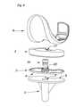
- FIG. 1is an exploded view of the prosthetic device of the present inventive concept.
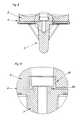
- FIG. 2is a section view through part of the prosthetic device of the present inventive concept.
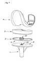
- FIG. 3shows the prosthetic device of the present inventive concept with the bearing portion (articular and base portions) in one of many possible assembled positions, in this case rotated 10 degrees relative to the tray portion.
- FIG. 4is an exploded view of another embodiment of the prosthetic device of the present inventive concept.
- FIG. 5is a section view through part of the embodiment depicted in FIG. 4 .
- FIG. 6is a detailed view of FIG. 5 , with the area of detail indicated by the circle (C) in FIG. 5 .
- FIG. 7is an exploded view of another embodiment of the prosthetic device of the present inventive concept.
- FIG. 8is a section view through part of the embodiment depicted in FIG. 7 .
- FIG. 9is a detailed view of FIG. 8 , with the area of detail indicated by the circle (C) in FIG. 8 .
- the present inventive conceptis related to the tibial component of a knee replacement prosthesis for both cemented and cementless applications; however the inventive concept is also applicable to other implantable prostheses such as ankles, fingers, and elbows, all of which may include a tray portion for resurfacing one or both sides of a joint.
- the present inventive conceptis particularly advantageous in allowing optimal sizing and placement for use in an artificial knee and as such this description will reference a knee prosthesis.
- the components that comprise these devicesare designed such that assembly of the components can be accomplished either before implantation, such as on the back table during surgery, or, alternatively the assembly can be accomplished in a successive fashion, assembling each portion independently during implantation to maximize the benefits of independent positioning of the individual sub-components of the device in the joint.
- the tibial component articular portioncan be fixedly set in place, or it can be left free to rotate after implantation, employing metal-on-metal bearing surfaces for the rotational motion.
- the present inventive conceptcan be achieved by de-coupling the tibial tray and tibial bearing portions, resulting in two or more distinct pieces.
- the tibial articular portionarticulates with the femoral portion that is in direct contact with the femur to provide functional replacement of the knee joint.
- the tibial base portionsupports this tibial articular portion, and the tibial tray portion in turn supports the tibial base portion.
- the tibial tray portionis in direct contact with the proximal tibia.
- the tibial articular portion and tibial base portionmay be preassembled during manufacture or may be removably attached by the user (surgeon), forming the tibial bearing portion.
- the usermay combine the tibial bearing portion with the tibial tray portion. This achieves additional variable positioning independent of that achieved after insertion of the tray portion.
- the tibial bearing portioncan be locked to the tray portion within a range of rotational positions to achieve the desired rotational alignment with the femoral component.
- the tibial bearing portionis free to rotate on the tibial tray portion after assembly.
- Sizes of the tray portion and the femoral portioncan also be independently selected, for proper fitment to the tibia and femur respectively, while maintaining a size match between the tibial articular portion and the femoral portion. Many different clinical situations can be addressed by simply using the appropriate combination of tibial tray, base, and articular portions, and femoral portions.
- a cylindrical press-fit coupling mechanism between the tibial base portion and the tibial tray portionprovides a reproducible strength and geometry of assembly between the two portions; this coupling mechanism only requires axial translation of the coupling mechanism, where full assembly is defined by seating of the base portion to the tray portion, which could not be achieved with the use of a tapered coupling mechanism.
- the coupling mechanismitself is either integral to the base portion or is accomplished with a separate portion that couples to the base and tray portions. Provided the coupling mechanism is fully assembled, the resulting strength of assembly and the axial position of the base portion relative to the tray portion are dependent on the design and manufacturing tolerances, and are not dependent on the magnitude of force applied during assembly, unlike tapered and/or threaded coupling mechanism.
- connection mechanism between the componentsis simplified and common amongst the components resulting in a reliable, more cost effective, and user friendly mechanism to secure the components either prior to, immediately prior to, or during implantation.
- FIG. 1there is a tray portion ( 1 ) of the device that is the portion that interfaces to the proximal end of the tibia.
- the tray portion ( 1 )is independent from the tibial base portion ( 2 ), the two portions being assembled and joined by the attachment mechanism shown in FIG. 2 .
- the tibial articular portion ( 3 )fixedly attaches to the base portion ( 2 ), together forming the tibial bearing portion.
- the tibial articular portion ( 3 )articulates with the femoral portion ( 4 ) to complete a functional knee replacement.
- the knee replacementmay include a patellar portion (not shown), for resurfacing or replacing the patella, that articulates with the femoral portion.
- the assembly of the deviceis not limited temporally, in that assembly can occur before surgery, immediately prior to implantation, or during implantation.
- the distal portion of the tibial traymay include one or more stems ( 10 ), ribs ( 11 ), pegs or other geometric or surface features for stabilization in the tibia.
- a bore ( 7 )Centrally located on the proximal end of the tray is a bore ( 7 ) with a central axis that is oriented normal to the proximal surface ( 5 ) of the tray.
- the bore ( 7 )may include threads or other feature ( 12 ) for engaging a screw, bolt, rod, or similar, which may be removably engaged to the tray portion ( 1 ).
- Such rod, or similarmay be used as part of an assembly device, to apply an assembly force to the tray while such device applies an opposite force to the bearing portion, to forcibly assemble the bearing portion into the tray.
- the bore ( 7 )may also serve as a mechanism of removing the tray from the bone in which the tray is implanted using a suitable instrument that removably engages the tray.
- the base portion ( 2 )is independent of the tray portion ( 1 ) and assembled and joined to the tray portion by the user (typically the surgeon). This modular feature is what allows the user additional flexibility in final knee replacement configuration. By de-coupling tray placement from the articular surface orientation, substantially more flexibility is allowed and the ability to address internal or external rotational mal-alignment becomes available. In addition, optimal sizing (including thickness, width, and breadth) may be achieved by choosing the appropriate articular and base portions to use with the chosen tray portion.
- the base portion ( 2 )includes a male spigot ( 8 ) that inserts in a co-axial manner into the bore ( 7 ) in the tray portion ( 1 ).
- the proximal surface ( 5 ) of the tray portion and the distal surface ( 6 ) of the base portionhave mutually conforming surfaces that come into direct contact upon assembly of the base portion to the tray portion.
- Final locking of the base portion ( 2 ) to the tray portion ( 1 )is obtained by the male spigot ( 8 ) of the base portion ( 2 ) locking within the corresponding bore ( 7 ) of the tray portion ( 1 ).
- One or more zones of diametrical interference between the spigot ( 8 ) and bore ( 7 )achieve this locking.
- the engaging surfaces of the spigot and boreare cylindrical.
- the outside diameter of the spigotexceeds the inside diameter of the bore, which defines the diametrical interference.
- the diametrical interference between the spigot and the boreis critical to proper functioning of the device, and may be in the range of 0.0005′′ to 0.0035′′.
- the preferred embodimentutilizes a nominal diametrical interference of 0.0020′′.
- the length of the zone of diametrical interferencemay be limited to approximately 0.02′′ to 0.10′′ to provide adequate rotational resistance of the base portion within the tray portion, while maintaining reasonable assembly forces by controlling the amount of interference, the length of the zone and the axial location of the zone(s).
- both the spigot ( 8 ) and bore ( 7 )incorporate gradual tapers and/or rounds at the surfaces leading into the zones of diametrical interference so as to avoid plowing of one or more surfaces during assembly, and thus ease assembly of the base portion to the tray portion.
- the total length of the spigot ( 8 ) and the location of the cylindrical zone with diametrical interference ( 13 and 14 of the spigot and bore, respectively)is not critical, it only requires a length and location to ensure a suitable locking surface with adequate axial and torsional engagement. It has been determined that an axial length of diametrical interference of approximately 0.08′′ and a total length of the spigot ( 8 ) of 0.3′′ are satisfactory for the tibial component of a knee replacement.
- the tibial articular portion ( 3 ) and tibial base portion ( 2 )may be distinct modular components that are assembled by the user prior to implantation, or assembled by the user during implantation.
- One or more of a variety of a locking mechanism ( 15 and 16 )may be utilized to fixedly combine the articular portion and the base portion.
- assembly of the two portions into a single portionmay effectively combine these two portions into a single portion during manufacture, or by replacing the two portions with a single portion that provides the same functionality as the two portions in combination.
- the tibial articular portion and tibial base portiontogether comprise the tibial bearing portion.
- the tibial base portion ( 2 ) and tibial articular portion ( 3 )may include through holes ( 17 and 18 ) coaxial to the spigot ( 8 ). These through holes ( 17 and 18 ) may include threads or other mechanisms for removable engagement of a bolt, rod, or plug, together or separately and for various purposes.
- a bolt or rodcould provide a mechanism of removing the base portion from the tray portion, or removing the assembled construct from the bone.
- a plugcould be used to close the hole and keep the internal surfaces clean.
- the through holes ( 17 and 18 )could also be used to enable a rod to pass through the base portion ( 2 ) and articular portion ( 3 ), said rod removably engaging the tray portion ( 1 ) at the hole ( 12 ), as part of a device to forcibly assemble the base portion into the tray portion.
- a bolt or other fastenercould further secure the tibial bearing portion to the tray portion.
- a coupler portion ( 19 )is used to achieve the cylindrical press-fit engagement of the base portion ( 2 ) to the tray portion ( 1 ).
- the function of the spigot ( 8 ) on the base portionis replaced by the coupler portion ( 19 ).
- the coupler portionincludes two zones of diametrical interference, one of which engages the tibial base ( 21 ) and the other of which engages the bore in the tray ( 22 ).
- the coupler portion ( 19 )is inserted through the hole in the base ( 20 ), until the coupler engages the base and the tray at these zones of diametrical interference, and fully seats the distal surface of the base ( 6 ) against the proximal surface of the tray ( 5 ).
- the engaging surfaces of the coupler, base, and boreare cylindrical.
- each of zones 21 and 22has a mating surface with a constant non-tapering cross-sectional geometry along its length.
- the diameter of the coupler at the distal zone of interference ( 22 )may be smaller than the diameter of the base at the proximal zone of interference ( 21 ).
- the diametrical interference between the coupler and the base at the proximal zone ( 22 ), and between the coupler and the bore at the distal zone ( 21 ),are critical to proper functioning of the device, and may each be in the range of 0.0005′′ to 0.0035′′.
- the preferred embodimentutilizes a nominal diametrical interference of 0.0020′′ at each of the two zones of interference fit ( 21 and 22 ).
- the length of the zones of diametrical interferencemay be limited to approximately 0.02′′ to 0.10′′ to provide adequate rotational resistance of the base portion within the tray portion, while maintaining reasonable assembly forces by controlling the amount of interference, the length of the zones and the axial location of the zones.
- the coupler ( 19 ), base ( 2 ), and bore ( 7 )incorporate gradual tapers and/or rounds at the surfaces leading into the zones of diametrical interference so as to avoid plowing of one or more surfaces during assembly, and thus ease assembly of the coupler portion to the base and tray portions.
- the total length of the coupler ( 19 ) and the location of the cylindrical zones with diametrical interference ( 21 and 22 )are not critical, they only require length and locations to ensure suitable locking surfaces and adequate axial and torsional engagement. It has been determined that a length of engagement of diametrical interference of approximately 0.08′′ between the coupler and the bore ( 22 ) and a length of engagement of diametrical interference of approximately 0.02′′ between the coupler and the base ( 21 ) are satisfactory for the tibial component of a knee replacement.
- the male spigot ( 23 )is part of the tibial tray ( 1 ), and this spigot engages the bore ( 20 ) in the base to achieve the cylindrical press-fit engagement of the base portion ( 2 ) to the tray portion ( 1 ).
- the spigot ( 23 )includes at least on zone of diametrical interference ( 24 ), which engages the tibial base ( 2 ).
- the base portion ( 2 )is placed on top of the tray portion ( 1 ), with the spigot ( 23 ) inserted in the hole in the base ( 20 ), engaging the spigot with the base at the zone of diametrical interference ( 24 ), and pressing the base portion onto the tray portion until the distal surface of the base ( 6 ) is fully seated against the proximal surface of the tray ( 5 ).
- the engaging surfaces of the spigot and boreare cylindrical. To obtain the interference fit between the spigot and the bore, the outside diameter of the spigot exceeds the inside diameter of the bore.
- the diametrical interference between the spigot and the boreis critical to proper functioning of the device, and may each be in the range of 0.0005′′ to 0.0035′′.
- the preferred embodimentutilizes a nominal diametrical interference of 0.0020′′ at the zone of interference fit ( 24 ).
- the length of the zone of diametrical interferencemay be limited to approximately 0.02′′ to 0.10′′ to provide adequate rotational resistance of the base portion on the tray portion, while maintaining reasonable assembly forces by controlling the amount of interference, the length of the zone and the axial location of the zone.
- the spigot ( 23 ) and bore ( 20 )incorporate gradual tapers and/or rounds at the surfaces leading into the zones of diametrical interference so as to avoid plowing of one or more surfaces during assembly, and thus ease assembly of the base and tray portions.
- the total length of the spigot ( 23 ) and the location of the cylindrical zone with diametrical interference ( 24 )are not critical, they only require a length and location to ensure suitable locking surfaces and adequate axial and torsional engagement. It has been determined that a length of engagement of diametrical interference of approximately 0.06′′ between the spigot and the bore ( 24 ) is satisfactory for the tibial component of a knee replacement.
- a slip-fit engagementallows rotational motion of the tibial base portion ( 2 ) relative to the tibial tray portion ( 1 ) after assembly and during functional service.
- this slip-fit engagementis between the spigot ( 8 ) and the bore ( 7 ).
- this slip-fit engagementis between the coupler ( 19 ) and the bore in the base portion ( 20 ), or alternatively between the coupler ( 19 ) and the bore in the tray portion ( 7 ).
- this slip-fit engagementis between the spigot ( 23 ) and the bore ( 20 ).
- the tibial base portion ( 2 ) and the fixedly attached tibial articular portion ( 3 )can, as a unit, rotate about the axis of the cylindrical bore ( 7 or 20 ). This rotational freedom allows the tibial articular surface to remain in continuous alignment with the femoral component after implantation, with metal-on-metal bearing rather than the metal-on-plastic bearing of previous rotating platform or mobile bearing designs.
- the modular tibial base portion ( 2 ) and tibial articular portion ( 3 )allow one to utilize various bearing configurations with the same tray portion ( 1 ) allowing for multiple options for each and every tray.
- Variations of articular portions ( 3 )can include but not limited to different thickness articular portions, alternative materials or material processing, and various articular geometries. Articular geometries may include additional features for engaging the femoral component, such as a post as part of a posterior stabilized design.
- the coupler portion ( 19 )may form all or part of such a feature. When variations of femoral and/or patellar portions are included the design options multiply significantly with very little increase in number of individual sub-components.
- Femoral component optionsmay include, but are not limited to, well known unconstrained, semi-constrained, posterior stabilized, and hinged designs, with appropriate mating tibial articular portions.
- the tibial tray ( 1 ), base ( 2 ), and articular ( 3 ) portions, and the femoral ( 4 ) and patellar portions of this devicecan be fabricated from any suitable high strength biocompatible materials. Suitable materials include any of the titanium alloys, cobalt alloys, or stainless steel alloys. Preferred examples include cobalt chromium alloys for the tibial tray and base portions, and for the femoral portion, and ultrahigh molecular weight polyethylene for the tibial articular portion and the patellar portion.
- the polyethylene articular portioncan be machined from prefabricated stock material, or it can be compression molded from polyethylene powder as a separate unit, and assembled to the tibial base during manufacturer or by the user.
- the polyethylenecan be directly compression molded into the tibial base portion forming an integral unit at the time of manufacturer.
- the distal geometry and surface properties of the tray portioncan be any of a variety appropriate for interfacing with the recipient bone for cemented or cementless fixation.
- the geometry and surface properties of the femoral portion ( 4 ) on the generally concave surfacecan be any of a variety appropriate for interfacing with the recipient bone for cemented or cementless fixation.
Landscapes
- Health & Medical Sciences (AREA)
- Orthopedic Medicine & Surgery (AREA)
- Physical Education & Sports Medicine (AREA)
- Cardiology (AREA)
- Oral & Maxillofacial Surgery (AREA)
- Transplantation (AREA)
- Engineering & Computer Science (AREA)
- Biomedical Technology (AREA)
- Heart & Thoracic Surgery (AREA)
- Vascular Medicine (AREA)
- Life Sciences & Earth Sciences (AREA)
- Animal Behavior & Ethology (AREA)
- General Health & Medical Sciences (AREA)
- Public Health (AREA)
- Veterinary Medicine (AREA)
- Prostheses (AREA)
Abstract
Description
Claims (13)
Priority Applications (1)
| Application Number | Priority Date | Filing Date | Title |
|---|---|---|---|
| US12/820,742US8277513B2 (en) | 2004-02-26 | 2010-06-22 | Modular knee prosthesis |
Applications Claiming Priority (3)
| Application Number | Priority Date | Filing Date | Title |
|---|---|---|---|
| US54762704P | 2004-02-26 | 2004-02-26 | |
| US11/066,123US7753960B2 (en) | 2004-02-26 | 2005-02-25 | Modular knee prosthesis |
| US12/820,742US8277513B2 (en) | 2004-02-26 | 2010-06-22 | Modular knee prosthesis |
Related Parent Applications (1)
| Application Number | Title | Priority Date | Filing Date |
|---|---|---|---|
| US11/066,123ContinuationUS7753960B2 (en) | 2004-02-26 | 2005-02-25 | Modular knee prosthesis |
Publications (2)
| Publication Number | Publication Date |
|---|---|
| US20100262253A1 US20100262253A1 (en) | 2010-10-14 |
| US8277513B2true US8277513B2 (en) | 2012-10-02 |
Family
ID=34914972
Family Applications (2)
| Application Number | Title | Priority Date | Filing Date |
|---|---|---|---|
| US11/066,123Expired - Fee RelatedUS7753960B2 (en) | 2004-02-26 | 2005-02-25 | Modular knee prosthesis |
| US12/820,742Expired - Fee RelatedUS8277513B2 (en) | 2004-02-26 | 2010-06-22 | Modular knee prosthesis |
Family Applications Before (1)
| Application Number | Title | Priority Date | Filing Date |
|---|---|---|---|
| US11/066,123Expired - Fee RelatedUS7753960B2 (en) | 2004-02-26 | 2005-02-25 | Modular knee prosthesis |
Country Status (4)
| Country | Link |
|---|---|
| US (2) | US7753960B2 (en) |
| AU (1) | AU2005216267B2 (en) |
| DE (1) | DE112005000431T5 (en) |
| WO (1) | WO2005082039A2 (en) |
Families Citing this family (58)
| Publication number | Priority date | Publication date | Assignee | Title |
|---|---|---|---|---|
| US6558426B1 (en) | 2000-11-28 | 2003-05-06 | Medidea, Llc | Multiple-cam, posterior-stabilized knee prosthesis |
| US6719800B2 (en) | 2001-01-29 | 2004-04-13 | Zimmer Technology, Inc. | Constrained prosthetic knee with rotating bearing |
| US6485519B2 (en) | 2001-01-29 | 2002-11-26 | Bristol-Myers Squibb Company | Constrained prosthetic knee with rotating bearing |
| US7497874B1 (en) | 2001-02-23 | 2009-03-03 | Biomet Manufacturing Corp. | Knee joint prosthesis |
| US20020120340A1 (en) | 2001-02-23 | 2002-08-29 | Metzger Robert G. | Knee joint prosthesis |
| US7753960B2 (en)* | 2004-02-26 | 2010-07-13 | Omni Life Science, Inc. | Modular knee prosthesis |
| US20060142869A1 (en)* | 2004-12-23 | 2006-06-29 | Gross Thomas P | Knee prosthesis |
| US8333805B2 (en)* | 2006-03-20 | 2012-12-18 | Howmedica Osteonics Corp. | Composite joint implant |
| CA2648444C (en)* | 2006-04-04 | 2014-03-18 | Smith & Nephew, Inc. | Trial coupler systems and methods |
| WO2008024836A2 (en) | 2006-08-22 | 2008-02-28 | Exactech, Inc. | System and method for adjusting the thickness of a prosthesis |
| JP5448842B2 (en) | 2007-01-10 | 2014-03-19 | バイオメト マニファクチャリング コーポレイション | Knee joint prosthesis system and implantation method |
| US8163028B2 (en) | 2007-01-10 | 2012-04-24 | Biomet Manufacturing Corp. | Knee joint prosthesis system and method for implantation |
| US8328873B2 (en) | 2007-01-10 | 2012-12-11 | Biomet Manufacturing Corp. | Knee joint prosthesis system and method for implantation |
| US8562616B2 (en) | 2007-10-10 | 2013-10-22 | Biomet Manufacturing, Llc | Knee joint prosthesis system and method for implantation |
| US8187280B2 (en) | 2007-10-10 | 2012-05-29 | Biomet Manufacturing Corp. | Knee joint prosthesis system and method for implantation |
| US8632600B2 (en) | 2007-09-25 | 2014-01-21 | Depuy (Ireland) | Prosthesis with modular extensions |
| US8715359B2 (en) | 2009-10-30 | 2014-05-06 | Depuy (Ireland) | Prosthesis for cemented fixation and method for making the prosthesis |
| US20110035018A1 (en)* | 2007-09-25 | 2011-02-10 | Depuy Products, Inc. | Prosthesis with composite component |
| US8128703B2 (en) | 2007-09-28 | 2012-03-06 | Depuy Products, Inc. | Fixed-bearing knee prosthesis having interchangeable components |
| US9204967B2 (en)* | 2007-09-28 | 2015-12-08 | Depuy (Ireland) | Fixed-bearing knee prosthesis having interchangeable components |
| US8192498B2 (en) | 2008-06-30 | 2012-06-05 | Depuy Products, Inc. | Posterior cructiate-retaining orthopaedic knee prosthesis having controlled condylar curvature |
| US8236061B2 (en) | 2008-06-30 | 2012-08-07 | Depuy Products, Inc. | Orthopaedic knee prosthesis having controlled condylar curvature |
| US8206451B2 (en) | 2008-06-30 | 2012-06-26 | Depuy Products, Inc. | Posterior stabilized orthopaedic prosthesis |
| US9119723B2 (en) | 2008-06-30 | 2015-09-01 | Depuy (Ireland) | Posterior stabilized orthopaedic prosthesis assembly |
| US8828086B2 (en) | 2008-06-30 | 2014-09-09 | Depuy (Ireland) | Orthopaedic femoral component having controlled condylar curvature |
| US8187335B2 (en) | 2008-06-30 | 2012-05-29 | Depuy Products, Inc. | Posterior stabilized orthopaedic knee prosthesis having controlled condylar curvature |
| US9168145B2 (en) | 2008-06-30 | 2015-10-27 | Depuy (Ireland) | Posterior stabilized orthopaedic knee prosthesis having controlled condylar curvature |
| US9011547B2 (en) | 2010-01-21 | 2015-04-21 | Depuy (Ireland) | Knee prosthesis system |
| US8206452B2 (en)* | 2010-02-18 | 2012-06-26 | Biomet Manufacturing Corp. | Prosthetic device with damper |
| US8932364B2 (en)* | 2010-07-14 | 2015-01-13 | Howmedica Osteonics Corp. | Prosthetic knee void filers with splined fixation |
| US8764840B2 (en) | 2010-07-24 | 2014-07-01 | Zimmer, Inc. | Tibial prosthesis |
| ES2632995T3 (en) | 2010-07-24 | 2017-09-18 | Zimmer, Inc. | Asymmetric tibia components for a knee prosthesis |
| US8591594B2 (en) | 2010-09-10 | 2013-11-26 | Zimmer, Inc. | Motion facilitating tibial components for a knee prosthesis |
| US8317870B2 (en) | 2010-09-30 | 2012-11-27 | Depuy Products, Inc. | Tibial component of a knee prosthesis having an angled cement pocket |
| US8287601B2 (en) | 2010-09-30 | 2012-10-16 | Depuy Products, Inc. | Femoral component of a knee prosthesis having an angled cement pocket |
| US8668743B2 (en) | 2010-11-02 | 2014-03-11 | Adam D. Perler | Prosthetic device with multi-axis dual bearing assembly and methods for resection |
| US8603101B2 (en) | 2010-12-17 | 2013-12-10 | Zimmer, Inc. | Provisional tibial prosthesis system |
| EP2675398A4 (en) | 2011-02-15 | 2017-01-25 | Omni Life Science, Inc. | Modular prosthesis |
| JP6029817B2 (en)* | 2011-09-27 | 2016-11-24 | 京セラメディカル株式会社 | Total knee implant |
| AU2012227339B2 (en)* | 2011-09-30 | 2015-07-02 | Depuy Products, Inc. | Tibial component of a knee prosthesis having an angled cement pocket |
| EP3175824B1 (en) | 2011-11-18 | 2019-01-02 | Zimmer, Inc. | Tibial bearing component for a knee prosthesis with improved articular characteristics |
| ES2585838T3 (en) | 2011-11-21 | 2016-10-10 | Zimmer, Inc. | Tibial base plate with asymmetric placement of fixing structures |
| IN2014DN07145A (en) | 2012-01-30 | 2015-04-24 | Zimmer Inc | |
| KR101184905B1 (en)* | 2012-02-17 | 2012-09-20 | 주식회사 코렌텍 | Artificial knee joint |
| US9393123B2 (en) | 2012-07-17 | 2016-07-19 | Clemson University Research Foundation | Lockable implants |
| FR2997625B1 (en)* | 2012-11-06 | 2015-09-04 | Implants Service Orthopedie Iso | KNEE PROSTHESIS |
| CN105392450B (en) | 2013-03-15 | 2017-09-29 | 马科外科公司 | Tibial knee list condyle implant |
| US9925052B2 (en) | 2013-08-30 | 2018-03-27 | Zimmer, Inc. | Method for optimizing implant designs |
| US20150289984A1 (en)* | 2014-04-15 | 2015-10-15 | Matthew D. BUDGE | Total Shoulder Arthroplasty Prosthesis |
| CN107106302B (en)* | 2014-11-06 | 2021-07-27 | 科辛顿有限公司 | Adjustable modular spacer device for the articulation of the knee |
| FR3032347B1 (en)* | 2015-02-05 | 2019-12-20 | Assistance Publique - Hopitaux De Paris | TOTAL KNEE PROSTHESIS WITH CERAMIC FRICTION TORQUE ON CERAMIC AND MOBILE CERAMIC TRAY. |
| WO2017053196A1 (en) | 2015-09-21 | 2017-03-30 | Zimmer, Inc. | Prosthesis system including tibial bearing component |
| US10675153B2 (en) | 2017-03-10 | 2020-06-09 | Zimmer, Inc. | Tibial prosthesis with tibial bearing component securing feature |
| WO2018208612A1 (en) | 2017-05-12 | 2018-11-15 | Zimmer, Inc. | Femoral prostheses with upsizing and downsizing capabilities |
| US11426282B2 (en) | 2017-11-16 | 2022-08-30 | Zimmer, Inc. | Implants for adding joint inclination to a knee arthroplasty |
| US10835380B2 (en) | 2018-04-30 | 2020-11-17 | Zimmer, Inc. | Posterior stabilized prosthesis system |
| USD961079S1 (en)* | 2020-10-27 | 2022-08-16 | Depuy Ireland Unlimited Company | Tibial protection plate |
| CN112545720A (en)* | 2020-12-16 | 2021-03-26 | 上海联影智融医疗科技有限公司 | Tibial bearing component |
Citations (114)
| Publication number | Priority date | Publication date | Assignee | Title |
|---|---|---|---|---|
| US3816855A (en) | 1971-06-01 | 1974-06-18 | Nat Res Dev | Knee joint prosthesis |
| US3868730A (en) | 1973-09-24 | 1975-03-04 | Howmedica | Knee or elbow prosthesis |
| US3869729A (en) | 1972-01-05 | 1975-03-11 | Nat Res Dev | Bone joint prosthesis |
| US4016606A (en) | 1975-07-14 | 1977-04-12 | Research Corporation | Knee joint prosthesis |
| US4136405A (en) | 1977-04-29 | 1979-01-30 | Zimmer U.S.A. | Rotational offset knee prosthesis |
| US4212087A (en) | 1978-11-16 | 1980-07-15 | Mortensen Lavaugh L | Prosthetic leg with a hydraulic control |
| US4213209A (en) | 1978-05-22 | 1980-07-22 | New York Society For The Relief Of The Ruptured And Crippled | Knee joint prosthesis |
| US4216549A (en) | 1977-06-02 | 1980-08-12 | Purdue Research Foundation | Semi-stable total knee prosthesis |
| US4219893A (en) | 1977-09-01 | 1980-09-02 | United States Surgical Corporation | Prosthetic knee joint |
| US4224697A (en) | 1978-09-08 | 1980-09-30 | Hexcel Corporation | Constrained prosthetic knee |
| US4262368A (en) | 1979-09-24 | 1981-04-21 | Wright Manufacturing Company | Rotating and hinged knee prosthesis |
| US4268920A (en) | 1977-10-05 | 1981-05-26 | GMT Gesellschaft fur med. Technik mbH | Endoprosthesis for a knee joint |
| US4301553A (en) | 1975-08-15 | 1981-11-24 | United States Surgical Corporation | Prosthetic knee joint |
| US4479271A (en) | 1981-10-26 | 1984-10-30 | Zimmer, Inc. | Prosthetic device adapted to promote bone/tissue ingrowth |
| US4634444A (en) | 1984-02-09 | 1987-01-06 | Joint Medical Products Corporation | Semi-constrained artificial joint |
| US4731086A (en) | 1987-04-20 | 1988-03-15 | Dow Corning Wright | Shim for femoral knee joint prosthesis and method of using |
| US4822366A (en) | 1986-10-16 | 1989-04-18 | Boehringer Mannheim Corporation | Modular knee prosthesis |
| US4838891A (en) | 1984-11-28 | 1989-06-13 | Branemark Per Ingvar | Joint prothesis |
| US4865606A (en) | 1987-08-13 | 1989-09-12 | Friedrichsfeld Gmbh Keramik Und Kunststoffwerke | Endoprosthesis for a knee-joint |
| US4888021A (en) | 1988-02-02 | 1989-12-19 | Joint Medical Products Corporation | Knee and patellar prosthesis |
| US4936847A (en) | 1988-12-27 | 1990-06-26 | Johnson & Johnson Orthopaedics, Inc. | Revision knee prosthesis |
| US4938769A (en) | 1989-05-31 | 1990-07-03 | Shaw James A | Modular tibial prosthesis |
| US4944756A (en) | 1988-02-03 | 1990-07-31 | Pfizer Hospital Products Group | Prosthetic knee joint with improved patellar component tracking |
| US4944757A (en) | 1988-11-07 | 1990-07-31 | Martinez David M | Modulator knee prosthesis system |
| US4950298A (en) | 1988-04-08 | 1990-08-21 | Gustilo Ramon B | Modular knee joint prosthesis |
| US4995883A (en) | 1989-02-08 | 1991-02-26 | Smith & Nephew Richards Inc. | Modular hip prosthesis |
| US5002578A (en) | 1990-05-04 | 1991-03-26 | Venus Corporation | Modular hip stem prosthesis apparatus and method |
| US5007933A (en) | 1989-01-31 | 1991-04-16 | Osteonics Corp. | Modular knee prosthesis system |
| US5030234A (en) | 1989-12-12 | 1991-07-09 | Pappas Michael J | Prosthetic device with modular stem |
| US5047033A (en) | 1989-02-08 | 1991-09-10 | Smith & Nephew Richards Inc. | Mill and guide apparatus for preparation of a hip prosthesis |
| US5074879A (en) | 1990-10-26 | 1991-12-24 | Pappas Michael J | Prosthetic device with modular stem |
| US5080674A (en) | 1988-09-08 | 1992-01-14 | Zimmer, Inc. | Attachment mechanism for securing an additional portion to an implant |
| US5108452A (en) | 1989-02-08 | 1992-04-28 | Smith & Nephew Richards Inc. | Modular hip prosthesis |
| US5116375A (en) | 1990-08-27 | 1992-05-26 | Hofmann Aaron A | Knee prosthesis |
| US5147405A (en) | 1990-02-07 | 1992-09-15 | Boehringer Mannheim Corporation | Knee prosthesis |
| US5147406A (en) | 1991-04-22 | 1992-09-15 | Zimmer, Inc. | Femoral component for a knee joint prosthesis having a modular cam and stem |
| US5163961A (en) | 1991-04-17 | 1992-11-17 | Harwin Steven F | Compression-fit hip prosthesis and procedures for implantation thereof |
| US5194066A (en) | 1988-01-11 | 1993-03-16 | Boehringer Mannheim Corporation | Modular joint prosthesis |
| US5197488A (en) | 1991-04-05 | 1993-03-30 | N. K. Biotechnical Engineering Co. | Knee joint load measuring instrument and joint prosthesis |
| US5207711A (en) | 1990-01-08 | 1993-05-04 | Caspari Richard B | Knee joint prosthesis |
| US5236461A (en) | 1991-03-22 | 1993-08-17 | Forte Mark R | Totally posterior stabilized knee prosthesis |
| US5246459A (en) | 1992-02-24 | 1993-09-21 | Elias Sarmed G | Modular tibial support pegs for the tibial component of a prosthetic knee replacement system |
| US5271747A (en) | 1992-01-14 | 1993-12-21 | Sulzer Medizinaltechnik Ag | Meniscus platform for an artificial knee joint |
| US5282867A (en) | 1992-05-29 | 1994-02-01 | Mikhail Michael W E | Prosthetic knee joint |
| US5314481A (en) | 1992-11-12 | 1994-05-24 | Wright Medical Technology, Inc. | Hinged knee prosthesis with extended patellar track |
| US5330534A (en) | 1992-02-10 | 1994-07-19 | Biomet, Inc. | Knee joint prosthesis with interchangeable components |
| US5358527A (en) | 1991-03-22 | 1994-10-25 | Forte Mark R | Total knee prosthesis with resurfacing and posterior stabilization capability |
| US5370699A (en) | 1993-01-21 | 1994-12-06 | Orthomet, Inc. | Modular knee joint prosthesis |
| US5370701A (en) | 1990-09-28 | 1994-12-06 | Arch Development Corporation | Rotating/sliding contrained prosthetic knee |
| US5395401A (en) | 1991-06-17 | 1995-03-07 | Bahler; Andre | Prosthetic device for a complex joint |
| US5405394A (en) | 1992-03-24 | 1995-04-11 | Smith & Nephew Richards, Inc. | Dual composition coupler for modular medical implants |
| EP0679375A1 (en) | 1994-04-25 | 1995-11-02 | EUROS Société Anonyme | Modular prosthetic set for the shoulder joint |
| US5480443A (en) | 1992-01-31 | 1996-01-02 | Elias; Sarmed G. | Artifical implant component and method for securing same |
| US5489311A (en) | 1994-01-21 | 1996-02-06 | Joint Medical Products Corporation | Prosthesis with orientable bearing surface |
| US5507824A (en) | 1993-02-23 | 1996-04-16 | Lennox; Dennis W. | Adjustable prosthetic socket component, for articulating anatomical joints |
| US5514183A (en) | 1994-12-20 | 1996-05-07 | Epstein; Norman | Reduced friction prosthetic knee joint utilizing replaceable roller bearings |
| US5549689A (en) | 1994-11-28 | 1996-08-27 | Epstein; Norman | Prosthetic knee |
| US5556433A (en) | 1994-12-01 | 1996-09-17 | Johnson & Johnson Professional, Inc. | Modular knee prosthesis |
| US5601567A (en) | 1994-06-30 | 1997-02-11 | Howmedica Inc. | Method of sizing a femoral canal using a modular femoral trial hip replacement system |
| US5653764A (en) | 1994-02-17 | 1997-08-05 | Murphy; Stephen B. | Modular hip prosthesis with discrete selectable angular orientation |
| US5653765A (en) | 1994-07-01 | 1997-08-05 | Ortho Development Corporation | Modular prosthesis |
| US5658341A (en) | 1993-03-10 | 1997-08-19 | Medinov S.A. | Tibial implant for a knee prosthesis |
| US5683472A (en) | 1995-12-29 | 1997-11-04 | Johnson & Johnson Professional, Inc. | Femoral stem attachment for a modular knee prosthesis |
| US5702480A (en) | 1992-10-13 | 1997-12-30 | Kropf; Philipp Rolf | Modular hip joint prosthesis |
| US5755804A (en) | 1996-02-21 | 1998-05-26 | Plus Endoprothetik Ag | Endoprosthetic knee joint |
| US5766257A (en) | 1997-01-28 | 1998-06-16 | Implant Manufacturing And Testing Corporation | Artificial joint having natural load transfer |
| US5782921A (en) | 1996-07-23 | 1998-07-21 | Johnson & Johnson Professional, Inc. | Modular knee prosthesis |
| US5871545A (en) | 1994-09-14 | 1999-02-16 | Btg International Limited | Prosthetic knee joint device |
| US5876459A (en) | 1996-08-30 | 1999-03-02 | Powell; Douglas Hunter | Adjustable modular orthopedic implant |
| US5879392A (en) | 1996-05-08 | 1999-03-09 | Mcminn; Derek James Wallace | Knee prosthesis |
| US5879391A (en) | 1996-09-30 | 1999-03-09 | Johnson & Johnson Professional, Inc. | Modular prosthesis |
| US5906644A (en) | 1996-08-30 | 1999-05-25 | Powell; Douglas Hunter | Adjustable modular orthopedic implant |
| US5941911A (en) | 1997-01-16 | 1999-08-24 | Buechel; Frederick F. | Orthopedic prosthesis employing bone screws and cement |
| US5954770A (en) | 1996-02-21 | 1999-09-21 | Plus Endoprothetik Ag | Endoprosthetic knee joint |
| US5957979A (en) | 1997-12-12 | 1999-09-28 | Bristol-Myers Squibb Company | Mobile bearing knee with metal on metal interface |
| US5964808A (en) | 1996-07-11 | 1999-10-12 | Wright Medical Technology, Inc. | Knee prosthesis |
| US6080195A (en) | 1998-07-08 | 2000-06-27 | Johnson & Johnson Professional, Inc. | Rotatable and translatable joint prosthesis with posterior stabilization |
| US6099570A (en) | 1997-10-28 | 2000-08-08 | Sulzer Orthopaedie Ag | Knee joint prothesis |
| US6099569A (en) | 1996-07-24 | 2000-08-08 | Waldemar Link (Gmbh & Co.) | Endoprosthesis |
| US6139581A (en) | 1997-06-06 | 2000-10-31 | Depuy Orthopaedics, Inc. | Posterior compensation tibial tray |
| US6165223A (en) | 1999-03-01 | 2000-12-26 | Biomet, Inc. | Floating bearing knee joint prosthesis with a fixed tibial post |
| US6203576B1 (en) | 1996-12-09 | 2001-03-20 | Groupe Controle Dedienne Gcd Societe De Droit Francais | Complete knee joint prosthesis |
| US6214052B1 (en) | 1999-01-19 | 2001-04-10 | Sulzer Orthopedics Inc. | Tibial component with a reversible, adjustable stem |
| US6238436B1 (en) | 1994-11-19 | 2001-05-29 | Biomet, Merck Deutschland Gmbh | Modular artificial hip joint |
| US20010003803A1 (en) | 1999-12-13 | 2001-06-14 | Sulzer Orthopedics Ltd. | Kit for a knee joint prosthesis |
| US6299648B1 (en) | 2000-03-17 | 2001-10-09 | Hammill Manufacturing Co. | Locking hip prosthesis |
| US6306172B1 (en) | 1999-01-28 | 2001-10-23 | Johnson & Johnson Professional, Inc. | Modular tibial insert for prosthesis system |
| US20010034554A1 (en) | 2000-03-08 | 2001-10-25 | Pappas Michael J. | Posterior stabilized prosthetic knee replacement with bearing translation and dislocation prevention features |
| US6319286B1 (en) | 2000-03-13 | 2001-11-20 | Exactech, Inc | Modular hip prosthesis |
| US6355069B1 (en) | 1998-08-20 | 2002-03-12 | Depuys Orthopaedics, Inc. | Bone engaging prosthesis |
| US6413279B1 (en) | 1999-03-01 | 2002-07-02 | Biomet, Inc. | Floating bearing knee joint prosthesis with a fixed tibial post |
| US20020103541A1 (en) | 2001-01-29 | 2002-08-01 | Meyers John E. | Constrained prosthetic knee with rotating bearing |
| US6440171B1 (en) | 2001-02-27 | 2002-08-27 | Hammill Manuf. Co. | Double D key locking prosthesis |
| US20020156535A1 (en) | 2000-03-13 | 2002-10-24 | Biomedical Engineering Trust I | Posterior stabilized knee replacement with bearing translation for knees with retained collateral ligaments |
| US20030009231A1 (en) | 2001-06-30 | 2003-01-09 | Gundlapalli Rama Rao V. | Joint replacement prosthesis component with non linear insert |
| US20030009232A1 (en) | 1999-03-01 | 2003-01-09 | Robert Metzger | Floating bearing knee joint prosthesis with a fixed tibial post |
| US20030055508A1 (en) | 2001-02-23 | 2003-03-20 | Metzger Robert G. | Knee joint prosthesis |
| US6589283B1 (en) | 2001-05-15 | 2003-07-08 | Biomet, Inc. | Elongated femoral component |
| US20030153979A1 (en) | 2002-02-11 | 2003-08-14 | Dean Hughes | Posterior stabilized knee system prosthetic devices employing diffusion-hardened surfaces |
| US6616697B2 (en) | 2001-03-13 | 2003-09-09 | Nicholas G. Sotereanos | Hip implant assembly |
| US6620198B2 (en) | 1999-10-07 | 2003-09-16 | Exactech, Inc. | Composite bearing inserts for total knee joints |
| US6660039B1 (en) | 1998-05-20 | 2003-12-09 | Smith & Nephew, Inc. | Mobile bearing knee prosthesis |
| US20040002767A1 (en) | 2002-06-28 | 2004-01-01 | Joseph Wyss | Modular knee joint prosthesis |
| US6702854B1 (en) | 1999-06-01 | 2004-03-09 | Apex Surgical, Llc | Implantable joint prosthesis |
| US6702822B1 (en) | 1996-01-04 | 2004-03-09 | Joint Medical Products Corporation | Method and apparatus for fitting a prosthesis to a bone |
| US20040054416A1 (en) | 2002-09-12 | 2004-03-18 | Joe Wyss | Posterior stabilized knee with varus-valgus constraint |
| US6719800B2 (en) | 2001-01-29 | 2004-04-13 | Zimmer Technology, Inc. | Constrained prosthetic knee with rotating bearing |
| US20040117023A1 (en) | 2002-12-13 | 2004-06-17 | Gerbec Daniel E. | Modular implant for joint reconstruction and method of use |
| US6755864B1 (en) | 1999-09-24 | 2004-06-29 | Sulzer Orthopedics Ltd. | Tibia part for a knee joint prosthesis and a kit with a tibia part of this kind |
| US6773461B2 (en) | 2001-01-29 | 2004-08-10 | Zimmer Technology, Inc. | Constrained prosthetic knee with rotating bearing |
| US20040215345A1 (en) | 2003-02-04 | 2004-10-28 | Zimmer Technology, Inc. | Rotating/non-rotating tibia base plate/insert system |
| WO2005034817A1 (en) | 2003-10-09 | 2005-04-21 | Apex Surgical, Llc | Tapered joint prosthesis |
| US20050107886A1 (en) | 2001-12-21 | 2005-05-19 | Paul Crabtree | Hinged joint system |
| US20050203629A1 (en) | 2004-02-26 | 2005-09-15 | George Cipolletti | Modular knee prosthesis |
- 2005
- 2005-02-25USUS11/066,123patent/US7753960B2/ennot_activeExpired - Fee Related
- 2005-02-28WOPCT/US2005/006055patent/WO2005082039A2/enactiveApplication Filing
- 2005-02-28DEDE112005000431Tpatent/DE112005000431T5/ennot_activeWithdrawn
- 2005-02-28AUAU2005216267Apatent/AU2005216267B2/ennot_activeCeased
- 2010
- 2010-06-22USUS12/820,742patent/US8277513B2/ennot_activeExpired - Fee Related
Patent Citations (125)
| Publication number | Priority date | Publication date | Assignee | Title |
|---|---|---|---|---|
| US3816855A (en) | 1971-06-01 | 1974-06-18 | Nat Res Dev | Knee joint prosthesis |
| US3869729A (en) | 1972-01-05 | 1975-03-11 | Nat Res Dev | Bone joint prosthesis |
| US3868730A (en) | 1973-09-24 | 1975-03-04 | Howmedica | Knee or elbow prosthesis |
| US4016606A (en) | 1975-07-14 | 1977-04-12 | Research Corporation | Knee joint prosthesis |
| US4301553A (en) | 1975-08-15 | 1981-11-24 | United States Surgical Corporation | Prosthetic knee joint |
| US4136405A (en) | 1977-04-29 | 1979-01-30 | Zimmer U.S.A. | Rotational offset knee prosthesis |
| US4216549A (en) | 1977-06-02 | 1980-08-12 | Purdue Research Foundation | Semi-stable total knee prosthesis |
| US4219893A (en) | 1977-09-01 | 1980-09-02 | United States Surgical Corporation | Prosthetic knee joint |
| US4268920A (en) | 1977-10-05 | 1981-05-26 | GMT Gesellschaft fur med. Technik mbH | Endoprosthesis for a knee joint |
| US4213209A (en) | 1978-05-22 | 1980-07-22 | New York Society For The Relief Of The Ruptured And Crippled | Knee joint prosthesis |
| US4224697A (en) | 1978-09-08 | 1980-09-30 | Hexcel Corporation | Constrained prosthetic knee |
| US4212087A (en) | 1978-11-16 | 1980-07-15 | Mortensen Lavaugh L | Prosthetic leg with a hydraulic control |
| US4262368A (en) | 1979-09-24 | 1981-04-21 | Wright Manufacturing Company | Rotating and hinged knee prosthesis |
| US4479271A (en) | 1981-10-26 | 1984-10-30 | Zimmer, Inc. | Prosthetic device adapted to promote bone/tissue ingrowth |
| US4634444A (en) | 1984-02-09 | 1987-01-06 | Joint Medical Products Corporation | Semi-constrained artificial joint |
| US4838891A (en) | 1984-11-28 | 1989-06-13 | Branemark Per Ingvar | Joint prothesis |
| US4822366A (en) | 1986-10-16 | 1989-04-18 | Boehringer Mannheim Corporation | Modular knee prosthesis |
| US4731086A (en) | 1987-04-20 | 1988-03-15 | Dow Corning Wright | Shim for femoral knee joint prosthesis and method of using |
| US4865606A (en) | 1987-08-13 | 1989-09-12 | Friedrichsfeld Gmbh Keramik Und Kunststoffwerke | Endoprosthesis for a knee-joint |
| US5194066A (en) | 1988-01-11 | 1993-03-16 | Boehringer Mannheim Corporation | Modular joint prosthesis |
| US4888021A (en) | 1988-02-02 | 1989-12-19 | Joint Medical Products Corporation | Knee and patellar prosthesis |
| US4944756A (en) | 1988-02-03 | 1990-07-31 | Pfizer Hospital Products Group | Prosthetic knee joint with improved patellar component tracking |
| US4950298A (en) | 1988-04-08 | 1990-08-21 | Gustilo Ramon B | Modular knee joint prosthesis |
| US5080674A (en) | 1988-09-08 | 1992-01-14 | Zimmer, Inc. | Attachment mechanism for securing an additional portion to an implant |
| US4944757A (en) | 1988-11-07 | 1990-07-31 | Martinez David M | Modulator knee prosthesis system |
| US4936847A (en) | 1988-12-27 | 1990-06-26 | Johnson & Johnson Orthopaedics, Inc. | Revision knee prosthesis |
| US5007933A (en) | 1989-01-31 | 1991-04-16 | Osteonics Corp. | Modular knee prosthesis system |
| US5047033A (en) | 1989-02-08 | 1991-09-10 | Smith & Nephew Richards Inc. | Mill and guide apparatus for preparation of a hip prosthesis |
| US5108452A (en) | 1989-02-08 | 1992-04-28 | Smith & Nephew Richards Inc. | Modular hip prosthesis |
| US4995883A (en) | 1989-02-08 | 1991-02-26 | Smith & Nephew Richards Inc. | Modular hip prosthesis |
| US5507830A (en) | 1989-02-08 | 1996-04-16 | Smith & Nephew Richards Inc. | Modular hip prosthesis |
| US4938769A (en) | 1989-05-31 | 1990-07-03 | Shaw James A | Modular tibial prosthesis |
| US5030234A (en) | 1989-12-12 | 1991-07-09 | Pappas Michael J | Prosthetic device with modular stem |
| US5207711A (en) | 1990-01-08 | 1993-05-04 | Caspari Richard B | Knee joint prosthesis |
| US5147405A (en) | 1990-02-07 | 1992-09-15 | Boehringer Mannheim Corporation | Knee prosthesis |
| US5002578A (en) | 1990-05-04 | 1991-03-26 | Venus Corporation | Modular hip stem prosthesis apparatus and method |
| US5116375A (en) | 1990-08-27 | 1992-05-26 | Hofmann Aaron A | Knee prosthesis |
| US5370701A (en) | 1990-09-28 | 1994-12-06 | Arch Development Corporation | Rotating/sliding contrained prosthetic knee |
| US5074879A (en) | 1990-10-26 | 1991-12-24 | Pappas Michael J | Prosthetic device with modular stem |
| US5236461A (en) | 1991-03-22 | 1993-08-17 | Forte Mark R | Totally posterior stabilized knee prosthesis |
| US5358527A (en) | 1991-03-22 | 1994-10-25 | Forte Mark R | Total knee prosthesis with resurfacing and posterior stabilization capability |
| US5197488A (en) | 1991-04-05 | 1993-03-30 | N. K. Biotechnical Engineering Co. | Knee joint load measuring instrument and joint prosthesis |
| US5163961A (en) | 1991-04-17 | 1992-11-17 | Harwin Steven F | Compression-fit hip prosthesis and procedures for implantation thereof |
| US5147406A (en) | 1991-04-22 | 1992-09-15 | Zimmer, Inc. | Femoral component for a knee joint prosthesis having a modular cam and stem |
| US5395401A (en) | 1991-06-17 | 1995-03-07 | Bahler; Andre | Prosthetic device for a complex joint |
| US5271747A (en) | 1992-01-14 | 1993-12-21 | Sulzer Medizinaltechnik Ag | Meniscus platform for an artificial knee joint |
| US5480443A (en) | 1992-01-31 | 1996-01-02 | Elias; Sarmed G. | Artifical implant component and method for securing same |
| US5330534A (en) | 1992-02-10 | 1994-07-19 | Biomet, Inc. | Knee joint prosthesis with interchangeable components |
| US5246459A (en) | 1992-02-24 | 1993-09-21 | Elias Sarmed G | Modular tibial support pegs for the tibial component of a prosthetic knee replacement system |
| US5405394A (en) | 1992-03-24 | 1995-04-11 | Smith & Nephew Richards, Inc. | Dual composition coupler for modular medical implants |
| US5282867A (en) | 1992-05-29 | 1994-02-01 | Mikhail Michael W E | Prosthetic knee joint |
| US5702480A (en) | 1992-10-13 | 1997-12-30 | Kropf; Philipp Rolf | Modular hip joint prosthesis |
| US5314481A (en) | 1992-11-12 | 1994-05-24 | Wright Medical Technology, Inc. | Hinged knee prosthesis with extended patellar track |
| US5370699A (en) | 1993-01-21 | 1994-12-06 | Orthomet, Inc. | Modular knee joint prosthesis |
| US5507824A (en) | 1993-02-23 | 1996-04-16 | Lennox; Dennis W. | Adjustable prosthetic socket component, for articulating anatomical joints |
| US5658341A (en) | 1993-03-10 | 1997-08-19 | Medinov S.A. | Tibial implant for a knee prosthesis |
| US5489311A (en) | 1994-01-21 | 1996-02-06 | Joint Medical Products Corporation | Prosthesis with orientable bearing surface |
| US5653764A (en) | 1994-02-17 | 1997-08-05 | Murphy; Stephen B. | Modular hip prosthesis with discrete selectable angular orientation |
| EP0679375A1 (en) | 1994-04-25 | 1995-11-02 | EUROS Société Anonyme | Modular prosthetic set for the shoulder joint |
| US5601567A (en) | 1994-06-30 | 1997-02-11 | Howmedica Inc. | Method of sizing a femoral canal using a modular femoral trial hip replacement system |
| US5653765A (en) | 1994-07-01 | 1997-08-05 | Ortho Development Corporation | Modular prosthesis |
| US5871545A (en) | 1994-09-14 | 1999-02-16 | Btg International Limited | Prosthetic knee joint device |
| US6238436B1 (en) | 1994-11-19 | 2001-05-29 | Biomet, Merck Deutschland Gmbh | Modular artificial hip joint |
| US5549689A (en) | 1994-11-28 | 1996-08-27 | Epstein; Norman | Prosthetic knee |
| US5556433A (en) | 1994-12-01 | 1996-09-17 | Johnson & Johnson Professional, Inc. | Modular knee prosthesis |
| US5514183A (en) | 1994-12-20 | 1996-05-07 | Epstein; Norman | Reduced friction prosthetic knee joint utilizing replaceable roller bearings |
| US5683472A (en) | 1995-12-29 | 1997-11-04 | Johnson & Johnson Professional, Inc. | Femoral stem attachment for a modular knee prosthesis |
| US6702822B1 (en) | 1996-01-04 | 2004-03-09 | Joint Medical Products Corporation | Method and apparatus for fitting a prosthesis to a bone |
| US5954770A (en) | 1996-02-21 | 1999-09-21 | Plus Endoprothetik Ag | Endoprosthetic knee joint |
| US5755804A (en) | 1996-02-21 | 1998-05-26 | Plus Endoprothetik Ag | Endoprosthetic knee joint |
| US5879392A (en) | 1996-05-08 | 1999-03-09 | Mcminn; Derek James Wallace | Knee prosthesis |
| US5964808A (en) | 1996-07-11 | 1999-10-12 | Wright Medical Technology, Inc. | Knee prosthesis |
| US5782921A (en) | 1996-07-23 | 1998-07-21 | Johnson & Johnson Professional, Inc. | Modular knee prosthesis |
| US6099569A (en) | 1996-07-24 | 2000-08-08 | Waldemar Link (Gmbh & Co.) | Endoprosthesis |
| US5906644A (en) | 1996-08-30 | 1999-05-25 | Powell; Douglas Hunter | Adjustable modular orthopedic implant |
| US5876459A (en) | 1996-08-30 | 1999-03-02 | Powell; Douglas Hunter | Adjustable modular orthopedic implant |
| US5879391A (en) | 1996-09-30 | 1999-03-09 | Johnson & Johnson Professional, Inc. | Modular prosthesis |
| US6203576B1 (en) | 1996-12-09 | 2001-03-20 | Groupe Controle Dedienne Gcd Societe De Droit Francais | Complete knee joint prosthesis |
| US5941911A (en) | 1997-01-16 | 1999-08-24 | Buechel; Frederick F. | Orthopedic prosthesis employing bone screws and cement |
| US5766257A (en) | 1997-01-28 | 1998-06-16 | Implant Manufacturing And Testing Corporation | Artificial joint having natural load transfer |
| US6139581A (en) | 1997-06-06 | 2000-10-31 | Depuy Orthopaedics, Inc. | Posterior compensation tibial tray |
| US6099570A (en) | 1997-10-28 | 2000-08-08 | Sulzer Orthopaedie Ag | Knee joint prothesis |
| US5957979A (en) | 1997-12-12 | 1999-09-28 | Bristol-Myers Squibb Company | Mobile bearing knee with metal on metal interface |
| US6660039B1 (en) | 1998-05-20 | 2003-12-09 | Smith & Nephew, Inc. | Mobile bearing knee prosthesis |
| US6080195A (en) | 1998-07-08 | 2000-06-27 | Johnson & Johnson Professional, Inc. | Rotatable and translatable joint prosthesis with posterior stabilization |
| US6355069B1 (en) | 1998-08-20 | 2002-03-12 | Depuys Orthopaedics, Inc. | Bone engaging prosthesis |
| US6214052B1 (en) | 1999-01-19 | 2001-04-10 | Sulzer Orthopedics Inc. | Tibial component with a reversible, adjustable stem |
| US6306172B1 (en) | 1999-01-28 | 2001-10-23 | Johnson & Johnson Professional, Inc. | Modular tibial insert for prosthesis system |
| US6165223A (en) | 1999-03-01 | 2000-12-26 | Biomet, Inc. | Floating bearing knee joint prosthesis with a fixed tibial post |
| US6413279B1 (en) | 1999-03-01 | 2002-07-02 | Biomet, Inc. | Floating bearing knee joint prosthesis with a fixed tibial post |
| US20030009232A1 (en) | 1999-03-01 | 2003-01-09 | Robert Metzger | Floating bearing knee joint prosthesis with a fixed tibial post |
| US7044975B2 (en) | 1999-06-01 | 2006-05-16 | Apex Surgical, Llc | Joint prostheses and components thereof |
| US6702854B1 (en) | 1999-06-01 | 2004-03-09 | Apex Surgical, Llc | Implantable joint prosthesis |
| US6755864B1 (en) | 1999-09-24 | 2004-06-29 | Sulzer Orthopedics Ltd. | Tibia part for a knee joint prosthesis and a kit with a tibia part of this kind |
| US6620198B2 (en) | 1999-10-07 | 2003-09-16 | Exactech, Inc. | Composite bearing inserts for total knee joints |
| US20010003803A1 (en) | 1999-12-13 | 2001-06-14 | Sulzer Orthopedics Ltd. | Kit for a knee joint prosthesis |
| US20010034554A1 (en) | 2000-03-08 | 2001-10-25 | Pappas Michael J. | Posterior stabilized prosthetic knee replacement with bearing translation and dislocation prevention features |
| US6491726B2 (en) | 2000-03-08 | 2002-12-10 | Biomedical Engineering Trust I | Posterior stabilized prosthetic knee replacement with bearing translation and dislocation prevention features |
| US6475241B2 (en) | 2000-03-13 | 2002-11-05 | Biomedical Engineering Trust I | Posterior stabilized knee replacement with bearing translation for knees with retained collateral ligaments |
| US6319286B1 (en) | 2000-03-13 | 2001-11-20 | Exactech, Inc | Modular hip prosthesis |
| US20020156535A1 (en) | 2000-03-13 | 2002-10-24 | Biomedical Engineering Trust I | Posterior stabilized knee replacement with bearing translation for knees with retained collateral ligaments |
| US6299648B1 (en) | 2000-03-17 | 2001-10-09 | Hammill Manufacturing Co. | Locking hip prosthesis |
| US20020103541A1 (en) | 2001-01-29 | 2002-08-01 | Meyers John E. | Constrained prosthetic knee with rotating bearing |
| US6485519B2 (en) | 2001-01-29 | 2002-11-26 | Bristol-Myers Squibb Company | Constrained prosthetic knee with rotating bearing |
| US20040249467A1 (en) | 2001-01-29 | 2004-12-09 | Meyers John E. | Constrained prosthetic knee with rotating bearing |
| US6719800B2 (en) | 2001-01-29 | 2004-04-13 | Zimmer Technology, Inc. | Constrained prosthetic knee with rotating bearing |
| US6773461B2 (en) | 2001-01-29 | 2004-08-10 | Zimmer Technology, Inc. | Constrained prosthetic knee with rotating bearing |
| US20060142867A1 (en) | 2001-02-23 | 2006-06-29 | Robert G. Metzger Et Al. | Knee joint prosthesis |
| US20030055508A1 (en) | 2001-02-23 | 2003-03-20 | Metzger Robert G. | Knee joint prosthesis |
| US6440171B1 (en) | 2001-02-27 | 2002-08-27 | Hammill Manuf. Co. | Double D key locking prosthesis |
| US6616697B2 (en) | 2001-03-13 | 2003-09-09 | Nicholas G. Sotereanos | Hip implant assembly |
| US6589283B1 (en) | 2001-05-15 | 2003-07-08 | Biomet, Inc. | Elongated femoral component |
| US20030009231A1 (en) | 2001-06-30 | 2003-01-09 | Gundlapalli Rama Rao V. | Joint replacement prosthesis component with non linear insert |
| US20050107886A1 (en) | 2001-12-21 | 2005-05-19 | Paul Crabtree | Hinged joint system |
| US20030153979A1 (en) | 2002-02-11 | 2003-08-14 | Dean Hughes | Posterior stabilized knee system prosthetic devices employing diffusion-hardened surfaces |
| US20040162620A1 (en) | 2002-06-28 | 2004-08-19 | Joseph Wyss | Modular knee joint prosthesis |
| US20040002767A1 (en) | 2002-06-28 | 2004-01-01 | Joseph Wyss | Modular knee joint prosthesis |
| US20040054416A1 (en) | 2002-09-12 | 2004-03-18 | Joe Wyss | Posterior stabilized knee with varus-valgus constraint |
| US20050192672A1 (en) | 2002-09-12 | 2005-09-01 | Joe Wyss | Posterior stabilized knee with varus-valgus constraint |
| US20040117023A1 (en) | 2002-12-13 | 2004-06-17 | Gerbec Daniel E. | Modular implant for joint reconstruction and method of use |
| US6866683B2 (en) | 2002-12-13 | 2005-03-15 | Medicine Lodge, Inc. | Modular implant for joint reconstruction and method of use |
| US20040215345A1 (en) | 2003-02-04 | 2004-10-28 | Zimmer Technology, Inc. | Rotating/non-rotating tibia base plate/insert system |
| WO2005034817A1 (en) | 2003-10-09 | 2005-04-21 | Apex Surgical, Llc | Tapered joint prosthesis |
| US20050203629A1 (en) | 2004-02-26 | 2005-09-15 | George Cipolletti | Modular knee prosthesis |
| US7753960B2 (en)* | 2004-02-26 | 2010-07-13 | Omni Life Science, Inc. | Modular knee prosthesis |
Also Published As
| Publication number | Publication date |
|---|---|
| DE112005000431T5 (en) | 2007-02-22 |
| AU2005216267A1 (en) | 2005-09-09 |
| US7753960B2 (en) | 2010-07-13 |
| AU2005216267B2 (en) | 2008-11-13 |
| US20100262253A1 (en) | 2010-10-14 |
| WO2005082039A3 (en) | 2006-12-21 |
| US20050203629A1 (en) | 2005-09-15 |
| WO2005082039A2 (en) | 2005-09-09 |
Similar Documents
| Publication | Publication Date | Title |
|---|---|---|
| US8277513B2 (en) | Modular knee prosthesis | |
| AU2020200583B2 (en) | Knee prosthesis system with standard and distal offset joint line | |
| CN109561969B (en) | Elbow replacement device and method | |
| US8366782B2 (en) | Modular orthopaedic implant system with multi-use stems | |
| US6699290B1 (en) | Modular elbow | |
| EP1004283B1 (en) | Modular stem and sleeve prosthesis | |
| US6413279B1 (en) | Floating bearing knee joint prosthesis with a fixed tibial post | |
| US6800094B2 (en) | Mobile bearing patellar prosthesis with orbital translation | |
| AU2005201780B2 (en) | Prosthetic knee | |
| US6143034A (en) | Implantable hinged knee prosthesis having tibial baseplate | |
| AU2018204289B2 (en) | Modular knee prosthesis with multiple lengths of sleeves sharing a common geometry | |
| JPH08224263A (en) | Prosthetic joint with movable joint between two bones | |
| JP2011115647A (en) | Joint prosthesis with positionable head | |
| WO2001082842A1 (en) | Floating bearing knee joint prosthesis with a fixed tibial post | |
| US20060224243A1 (en) | Elbow prosthesis | |
| US20060100713A1 (en) | Mobile bearing total elbow prosthesis, ulnar component, and associated kit | |
| AU2014201526B2 (en) | Mechanical assembly of titanium foam pegs |
Legal Events
| Date | Code | Title | Description |
|---|---|---|---|
| AS | Assignment | Owner name:APEX SURGICAL, LLC, MASSACHUSETTS Free format text:ASSIGNMENT OF ASSIGNORS INTEREST;ASSIGNOR:HENRY, JAMES H.;REEL/FRAME:026208/0134 Effective date:20060818 Owner name:APEX SURGICAL, LLC, MASSACHUSETTS Free format text:ASSIGNMENT OF ASSIGNORS INTEREST;ASSIGNORS:CHEAL, EDWARD J.;CIPOLLETTI, GEORGE B.;SIGNING DATES FROM 20050929 TO 20050930;REEL/FRAME:026208/0118 Owner name:OMNI LIFE SCIENCE, INC., MASSACHUSETTS Free format text:ASSIGNMENT OF ASSIGNORS INTEREST;ASSIGNOR:APEX SURGICAL, LLC;REEL/FRAME:026208/0139 Effective date:20060915 | |
| STCF | Information on status: patent grant | Free format text:PATENTED CASE | |
| FEPP | Fee payment procedure | Free format text:PAYOR NUMBER ASSIGNED (ORIGINAL EVENT CODE: ASPN); ENTITY STATUS OF PATENT OWNER: LARGE ENTITY | |
| FPAY | Fee payment | Year of fee payment:4 | |
| AS | Assignment | Owner name:DEERFIELD MANAGEMENT COMPANY, L.P., NEW YORK Free format text:SECURITY INTEREST;ASSIGNOR:OMNI LIFE SCIENCE, INC.;REEL/FRAME:045990/0674 Effective date:20180529 | |
| AS | Assignment | Owner name:OMNI LIFE SCIENCE, INC., MASSACHUSETTS Free format text:RELEASE BY SECURED PARTY;ASSIGNOR:DEERFIELD MANAGEMENT COMPANY, L.P., AS COLLATERAL AGENT;REEL/FRAME:048908/0510 Effective date:20190405 | |
| FEPP | Fee payment procedure | Free format text:ENTITY STATUS SET TO UNDISCOUNTED (ORIGINAL EVENT CODE: BIG.); ENTITY STATUS OF PATENT OWNER: LARGE ENTITY | |
| MAFP | Maintenance fee payment | Free format text:PAYMENT OF MAINTENANCE FEE, 8TH YEAR, LARGE ENTITY (ORIGINAL EVENT CODE: M1552); ENTITY STATUS OF PATENT OWNER: LARGE ENTITY Year of fee payment:8 | |
| FEPP | Fee payment procedure | Free format text:MAINTENANCE FEE REMINDER MAILED (ORIGINAL EVENT CODE: REM.); ENTITY STATUS OF PATENT OWNER: LARGE ENTITY | |
| LAPS | Lapse for failure to pay maintenance fees | Free format text:PATENT EXPIRED FOR FAILURE TO PAY MAINTENANCE FEES (ORIGINAL EVENT CODE: EXP.); ENTITY STATUS OF PATENT OWNER: LARGE ENTITY | |
| STCH | Information on status: patent discontinuation | Free format text:PATENT EXPIRED DUE TO NONPAYMENT OF MAINTENANCE FEES UNDER 37 CFR 1.362 | |
| FP | Lapsed due to failure to pay maintenance fee | Effective date:20241002 |