US8277425B2 - Dual lumen port with F-shaped connector - Google Patents
Dual lumen port with F-shaped connectorDownload PDFInfo
- Publication number
- US8277425B2 US8277425B2US10/807,590US80759004AUS8277425B2US 8277425 B2US8277425 B2US 8277425B2US 80759004 AUS80759004 AUS 80759004AUS 8277425 B2US8277425 B2US 8277425B2
- Authority
- US
- United States
- Prior art keywords
- shaped flow
- lumens
- port
- stem
- wells
- Prior art date
- Legal status (The legal status is an assumption and is not a legal conclusion. Google has not performed a legal analysis and makes no representation as to the accuracy of the status listed.)
- Expired - Fee Related, expires
Links
Images


Classifications
- A—HUMAN NECESSITIES
- A61—MEDICAL OR VETERINARY SCIENCE; HYGIENE
- A61M—DEVICES FOR INTRODUCING MEDIA INTO, OR ONTO, THE BODY; DEVICES FOR TRANSDUCING BODY MEDIA OR FOR TAKING MEDIA FROM THE BODY; DEVICES FOR PRODUCING OR ENDING SLEEP OR STUPOR
- A61M39/00—Tubes, tube connectors, tube couplings, valves, access sites or the like, specially adapted for medical use
- A61M39/02—Access sites
- A61M39/0208—Subcutaneous access sites for injecting or removing fluids
- A—HUMAN NECESSITIES
- A61—MEDICAL OR VETERINARY SCIENCE; HYGIENE
- A61M—DEVICES FOR INTRODUCING MEDIA INTO, OR ONTO, THE BODY; DEVICES FOR TRANSDUCING BODY MEDIA OR FOR TAKING MEDIA FROM THE BODY; DEVICES FOR PRODUCING OR ENDING SLEEP OR STUPOR
- A61M39/00—Tubes, tube connectors, tube couplings, valves, access sites or the like, specially adapted for medical use
- A61M39/02—Access sites
- A61M39/04—Access sites having pierceable self-sealing members
- A61M39/045—Access sites having pierceable self-sealing members pre-slit to be pierced by blunt instrument
- A—HUMAN NECESSITIES
- A61—MEDICAL OR VETERINARY SCIENCE; HYGIENE
- A61M—DEVICES FOR INTRODUCING MEDIA INTO, OR ONTO, THE BODY; DEVICES FOR TRANSDUCING BODY MEDIA OR FOR TAKING MEDIA FROM THE BODY; DEVICES FOR PRODUCING OR ENDING SLEEP OR STUPOR
- A61M39/00—Tubes, tube connectors, tube couplings, valves, access sites or the like, specially adapted for medical use
- A61M39/02—Access sites
- A61M39/0208—Subcutaneous access sites for injecting or removing fluids
- A61M2039/0211—Subcutaneous access sites for injecting or removing fluids with multiple chambers in a single site
- A—HUMAN NECESSITIES
- A61—MEDICAL OR VETERINARY SCIENCE; HYGIENE
- A61M—DEVICES FOR INTRODUCING MEDIA INTO, OR ONTO, THE BODY; DEVICES FOR TRANSDUCING BODY MEDIA OR FOR TAKING MEDIA FROM THE BODY; DEVICES FOR PRODUCING OR ENDING SLEEP OR STUPOR
- A61M39/00—Tubes, tube connectors, tube couplings, valves, access sites or the like, specially adapted for medical use
- A61M39/10—Tube connectors; Tube couplings
- A61M39/12—Tube connectors; Tube couplings for joining a flexible tube to a rigid attachment
Definitions
- Kidney dialysis, chemotherapy and other chronic treatmentsmay have to be performed several times a week.
- a portmay be used to access the proximal end of the catheter from outside the body, for example, via a syringe.
- such portsare implanted subcutaneously in the arm or chest to provide protection to the port while maintaining easy access thereto.
- Such portstypically consist of a housing with one or more wells to receive therapeutic agents.
- the therapeutic agentsare fluids that cannot be mixed together outside of the body, but which preferably are infused together. These unmixable fluids may lose their potency or may become toxic if mixed prior to infusion in the body. They are therefore kept separate until they reach the blood stream.
- a separate cathetermay be used for each of the fluids with distal ends of the catheters (i.e., outlets) near one another.
- a multi-lumen cathetere.g., a dual lumen catheter
- each lumentransporting a different fluid.
- Providing two unmixable therapeutic fluids to a dual lumen catheter or to two separate catheters near each otherpresents challenges as a conventional port may not be useable to inject both fluids.
- Multiple. portsare generally not implanted near one another because of the surgery required to insert each port and additional complications that may arise with respect to each port.
- a dual well port device having two ports formed within a single housingmay be used with each port being connected to a different catheter or to a different lumen of a dual lumen catheter.
- conventional dual well port devicesare larger than single port devices, and may require more extensive surgery to be placed in the patient's body. The connections between the wells and the catheter further increase the width of the dual well port, so that a larger incision is often necessary to place such a port within the patient.
- the present inventionis directed to a port for subcutaneous implantation, comprising a housing including first and second wells formed therein and a substantially F-shaped flow element including first and second lumens extending therethrough wherein, when in an operative configuration the F-shaped flow element is coupled to the housing with a proximal end of each of the lumens in fluid communication with a respective one of the first and second wells for receiving fluid therefrom, and wherein distal ends of each of the lumens form outlets, each outlet being coupleable to a lumen of a medical catheter, the F-shaped flow element including first and second arms extending from a trunk with the first lumen extending through the first arm to the trunk and the second lumen extending through the second arm to the trunk, the first and second lumens being separated from one another within the trunk.
- the present inventionis further directed to a dual well port device comprising a housing defining first and second wells disposed along an axis of the housing in combination with an F-shaped flow element including first and second lumens independent of one another, the first lumen, when the flow element is in an operative configuration coupled to the housing, being fluidly connected to the first well and having an arm portion extending at a first angle relative to the axis and wherein, when in the operative configuration, the second lumen is fluidly connected to the second well and includes an arm portion extending at a second angle relative to the axis, the F-shaped flow element including a trunk enclosing trunk portions of the first and second lumens.
- the present inventionis further directed to a method of infusing fluids into a patient, comprising implanting distal ends first and second catheter lumens into a blood vessel and fluidly connecting each of the first and second catheter lumens to first and second flow element lumens of an F-shaped flow element, the first flow element lumen extending through the trunk and through the first arm to fluidly connect to a first well of a dual well port and the second flow element lumen extending through the trunk and the second arm to a second F arm to fluidly connect to a second well of the port, wherein the first and second flow element lumens are separated from one another in the trunk in combination with introducing a first fluid into the first well and introducing a second fluid into the second well so that the first and second fluids are passed to the blood vessel without intermingling with one another prior to leaving the distal ends of the first and second catheter lumens.
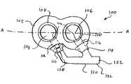
- FIG. 1is a perspective view of a dual well port according to an embodiment of the present invention
- FIG. 2is a top plan view of the dual well port according the embodiment of the present invention shown in FIG. 1 ;
- FIG. 3is a detail view of an F-shaped flow element according to an embodiment of the present invention.
- FIG. 4is a detail view of an F-shaped flow element according to another embodiment of the invention.
- FIG. 5is a top plan view of a different embodiment of the dual well port device according to the invention.
- the present inventionis related to medical devices that are used to access the vascular system of a patient.
- the present inventionrelates to access ports used to inject therapeutic agents into the vascular access devices.
- Central cathetersmay be kept in place for extended periods of time—up to two years or more.
- Central cathetersgenerally comprise a flexible elongated portion that is tunneled or otherwise placed within the patient's body in fluid contact with a blood vessel.
- the proximal end of such a central cathetermay be connected to a port placed subcutaneously in the arm or chest of the patient to selectively provide access to the catheter.
- These portsoften include a self sealing surface (e.g., a septum) that can be pierced by a needle passing through the skin, for injection of therapeutic agents thereinto.
- implantable cathetersinclude the catheters manufactured by VaxcelTM, such as the Chronic Dialysis Catheter and the Implantable Vascular Access System.
- a dual well portseparate wells are maintained to separate fluids which are to be presented separately to the bloodstream—i.e., which are not to mix together prior to entering the bloodstream.
- certain chemicalsmay react negatively if mixed together outside of the bloodstream or may lose their potency, etc.
- Each of the fluidsis injected into a corresponding one of the wells through a corresponding septum for the well (or through a portion of a common septum corresponding to the particular well) so that no mixing occurs in the port device.
- the lumens leading from each of the wells to the catheter (or catheters)also are separate and independent and, due to the size of the wells, are often disposed far apart from one another.
- Embodiments of the present inventionprovide for a configuration of the wells and lumens of a port device that allow a narrower cross section of the device, and therefore allows for a smaller incision through which the port device is implanted.
- a dual well port devicewhich comprises a pair of independent lumens, each extending from a corresponding one of the wells to the periphery of a well housing.
- the housing lumensare shaped and oriented to reduce a width of the port device itself and are independent so that the fluid in one lumen does not mix with that in the other lumen.
- a substantially F-shaped flow element, a proximal end of which attaches to the housing,comprises a pair of independent lumens each of which fluidly connects to a corresponding one of the housing lumens.
- a distal end of the F-shaped flow elementconnects to the proximal end of a dual lumen catheter (or to the proximal ends of two independent catheters) the distal end of which extends to the patient's vascular system.
- the configuration of the F-shaped flow elementalso reduces a frontal area of the dual well port device without sacrificing the flow carrying capacity of the port device.
- the housing lumensare preferably angled relative to an axis of the port along which the two wells are disposed so that the F-shaped flow element may be placed in close proximity to a side surface of the port housing.
- the housing's lumensare separate from the lumens defined by the F-shaped flow element.
- the F-shaped flow elementis a separate component, such as a connector that can be attached to the housing of the port device before or during surgical procedure to implant the port.
- the F-shaped flow elementmay be an integral part of the port's housing, such that a single lumen may extend from each of the wells to the dual lumen catheter or pair of catheters.
- the F-shaped flow elementthus may be a connector separate and independent from the housing of the port device, or may be an integral part of the housing, depending on the requirements of the situation being addressed and on the construction details of the dual well port device.
- the exemplary dual well portcomprises two separate wells and two separate septa that form independent flow chambers within the dual well port housing.
- the lumens extending through the housing from each of the wells and through the F-shaped flow elementform flow passages that are independent and isolated from one another, so fluids injected into the wells do not mix until the fluids have left the distal end of a catheter coupled to the port device.
- the disposition of the individual lumens extending from the wells and of the F-shaped flow elementare preferably selected to minimize the cross-sectional profile of the port device.
- the lumensmay extend at a selected angle from the wells as described below, to reduce the profile area of the port device and to maintain the flow carrying capacity of the lumens.
- the length and orientation of the F-shaped flow elementmay be varied to optimize the size and flow carrying capacity of the port device while providing a simple connection to the catheter(s) leading to the patient.
- an exemplary dual well port device 100comprises a housing 102 which defines two wells—a first well 104 and a second well 106 .
- Each of the wells 104 , 106includes an opening on its top side through which a fluid may be introduced into the corresponding well.
- Septums 108 , 110respectively seal the openings of the wells 104 , 106 and prevent fluid therein from leaking out of the port device 100 .
- the septums 108 , 110are preferably formed of a flexible, self sealing material which can be punctured repeatedly by a syringe's needle while retaining the ability to self-seal the puncture opening once the needle has been removed.
- each of the septums 108 , 110also forms a seal around the needle used to inject the fluids, so that a positive pressure may be applied through the needle to the fluid, e.g., to drive the fluid from the port device 100 into a catheter attached thereto and into the bloodstream.
- a first lumen 112extends from and is in fluid connection with the first well 104 and a second lumen 114 extends from and is in fluid communication with the second well 106 .
- the first and second lumens 112 , 114are separate and independent of one another and the first and second wells 104 , 106 are separate and independent from one another so that there is no fluid communication between the combination of the first lumen 112 with the first well 104 and the combination of the second lumen 114 and the second well 106 .
- the location of the openings 124 of each of the first and second lumens 112 , 114 into the corresponding one of the first and second wells 104 , 106 and the angle at which these lumens 112 , 114 meet their corresponding wells 104 , 106are preferably selected to provide a small profile to the port device 100 .
- the lumens 112 , 114are preferably disposed at an angle of between approximately 30° to approximately 60° from a longitudinal axis A-A of the port device 100 .
- the axis A-Amay also be the axis along which the wells 104 , 106 are disposed.
- the location of the openings 124may be optimized so that flow from inside the wells 104 , 106 to the corresponding one of the first and second lumens 112 , 114 is not impeded.
- the diameter of the lumens 112 , 114is preferably selected to provide a sufficient flow of fluid therethrough based on, for example, the flow requirement of the treatments for which the port device 100 is intended. Although larger diameter lumens handle higher flow rates, those skilled in the art will understand that the desired diameter may be limited by structural considerations related to, for example, the required strength of the housing 102 and by size constraints placed on the device 100 .
- Fluid injected into the well 104passes through the corresponding lumen 112 to the catheter via the F-shaped flow element 120 .
- fluid injected into the well 106passes through the lumen 114 to a catheter via the F-shaped flow element 120 .
- the F-shaped flow element 120includes a pair of arms 128 , 130 extending from a trunk 132 and defining a gap 109 between an outer surface of the port device 100 , the trunk 132 and the arms 128 , 130 .
- the substantial F-shape of the F-shaped flow element 102does not require that this element precisely mimic the letter F.
- the F-shape of the flow element 102refers more generally to a configuration where 2 arms project from a common trunk substantially parallel to one another at an angle (e.g., of between 15° and 75°) with respect to a longitudinal axis of the trunk.
- Each of the arms 128 , 130connects to a corresponding one of the lumens 112 , 114 so that fluid from each of the lumens 112 , 114 passes from the port device 100 into a corresponding one of two flow passages (lumens) formed in the trunk 132 to an outlet 122 while remaining separate from one another.
- the outlet 122may comprise an adapter designed to connect with an inlet of a catheter, for example, a dual lumen catheter.
- the length of the arms 128 , 130may be selected to reduce the profile of the port device 100 , for example by selecting a length of the trunk 132 to be a minimum distance which avoids interference with the housing 102 .
- the angle at which the arms 128 , 130 project from the trunk 132is also preferably selected to achieve the same goal.
- each of the arms 128 , 130extends along an axis substantially aligned with an axis of the corresponding one of the lumens 112 , 114 to reduce flow resistance within the F-shaped flow element 120 .
- variations from that orientationmay be desirable to construct a more compact port device 100 .
- the arms 128 , 130may be curved or may have a varying angular orientation to minimize the width of the port device 100 .
- the trunk 132may be substantially parallel to the longitudinal axis A-A of port 100 , or alternatively may be disposed at an angle thereto, as dictated by the requirements of the port device 100 .
- the outlets 116 , 118are disposed at the ends of lumens 112 , 114 , respectively, at the periphery of the housing 102 .
- the outlets 116 , 118may be used as adapters to connect the arms 128 , 130 respectively to the lumens 112 , 114 .
- These connectionsmay be releasable or may be permanent, depending on the specific requirements of the port device 100 .
- the manufacturing of the port device 100may be simplified by using the F-shaped flow element 120 as a separate connector which attaches to the outlets 116 , 118 .
- the housing 102 and the F-shaped flow element 120may be formed separately and assembled later in a finishing operation.
- the ability to form the housing 102 and the F-shaped flow element 120 separatelyalso simplifies tailoring the port device 100 to different applications, since an F-shaped flow element 120 for a particular application (e.g., assembly with a particular housing 102 ) may be selected from a group including an assortment of lengths and arm orientations to achieve a desired overall size and shape of the port device 100 .
- valves 126may be included in each of outlets 116 , 118 .
- Each valve 126may be, for example, a pressure actuated safety valve (PASV) which restricts flow through the outlets under certain conditions and allows flow therethrough under preselected flow conditions. For example, when the pressure of the fluid is below a predetermined threshold level, a flow control membrane in the PASV prevents the fluid from flowing therethrough. However, when the fluid pressure is increased above the threshold level, the membrane opens and lets the flow pass.
- PASVpressure actuated safety valve
- the valves 126may be of types other than PASV's.
- a check valvefor example, a check valve, a spring loaded valve or other type of flow control device may be used, to prevent fluid leakage, to control a direction of fluid flow and/or to control fluid pressure and flow rate.
- one or more flow control devicessuch as a valve 126 , may be disposed at one or more locations within the F-shaped flow element 120 , such as, for example, near the outlet 122 .
- FIG. 3shows a detail perspective view of an F-shaped flow element 120 according to an embodiment of the invention.
- a first arm 128defines a lumen adapted to fluidly connect with the well 104 of the port device 100 via the corresponding housing lumen 112 such that fluid injected into the well 104 travels to the outlet 122 .
- the second arm 130defines another lumen connected to the second well 106 of the port device 100 .
- the trunk 132is divided into two independent lumens so that fluid from each of the wells 104 , 106 reaches the outlet 122 without mixing with the fluid from the other well.
- a partition 204extends across an interior space of the trunk 132 to separate this space into independent lumens 200 and 202 .
- the lumen 200couples to the lumen in the arm 128 while the lumen 202 couples to the lumen in the arm 130 .
- the partition 204may be streamlined to minimize blockage and the turbulence imparted to flow through the lumens 200 , 202 .
- the F-shaped flow element 120comprises a trunk 132 that has a substantially circular cross section.
- the partition 204divides the trunk 132 into two lumens having substantially semi-circular cross sections.
- the cross-section of the trunk 132 and of the individual lumensmay be modified, to obtain desired cross sectional area and flow characteristics of the port device 100 .
- the lumens 200 , 202may be substantially elliptical, oval or of any other shape suitable to pass a desired flow rate of fluid therethrough.
- manufacturing an F-shaped flow element with a more complex lumen in the trunk thereofmay increase the difficulty and cost of construction relative to the simpler circular trunk described above.
- FIG. 4shows an exemplary alternate embodiment of an F-shaped flow element 320 , where the trunk 332 has a substantially semi-circular cross section.
- a partition 304defines two independent lumens 300 , 302 each of which has a substantially quarter circle cross-sectional shape. This configuration may be advantageous in cases where the overall thickness of the F-shaped flow element 320 is restricted to a predetermined level and/or where special packaging considerations of the port device 100 dictate such a shape or thickness.
- a dual well port device 400comprises two wells 402 , 404 that are fluidly connected to an F-shaped flow element 410 which is integral with a housing 412 of the port device 400 .
- arms 406 , 408are also integrally formed with the housing 412 with each extending from a respective one of the wells 402 , 404 to the trunk 418 .
- a partition 420may be used to divide the trunk 418 into independent lumens 414 , 416 , which maintain the fluids injected into the two wells 402 , 404 separate at least until reaching an outlet 422 of the F-shaped flow element 410 .
- the outlet 422may be adapted to fluidly connect to a dual lumen catheter (not shown) or to two separate catheters, each carrying the fluid injected into one of the wells 402 , 404 to an outlet in the bloodstream.
- a dual lumen catheternot shown
- two separate catheterseach carrying the fluid injected into one of the wells 402 , 404 to an outlet in the bloodstream.
- forming the F-shaped flow element 410 integrally with the housing 412 of the port device 400may achieve an additional reduction in the profile dimensions of the port device 400 .
- the more complex shape of the housing 412may increase the cost and/or difficulty of manufacturing the port device 400 .
- the dual well port devicecomprising an F-shaped flow element used to connect two wells of the port to the lumens of a catheter or to two separate catheters
- the angular orientation and/or the length of the arms of the F-shaped flow elementmay be varied to achieve a desired port device profile.
- further variationsmay be made to achieve a desired flow rate through the port device, for example by varying the width and/or cross-sectional shape of the various lumens of the port device and/or F-shaped flow element.
- the size of the dual well port device and of the F-shaped flow elementmay also be adjusted by varying the parameters described above, so that the port device may be placed subcutaneously with minimal discomfort to the patient.
Landscapes
- Health & Medical Sciences (AREA)
- Heart & Thoracic Surgery (AREA)
- Pulmonology (AREA)
- Engineering & Computer Science (AREA)
- Anesthesiology (AREA)
- Biomedical Technology (AREA)
- Hematology (AREA)
- Life Sciences & Earth Sciences (AREA)
- Animal Behavior & Ethology (AREA)
- General Health & Medical Sciences (AREA)
- Public Health (AREA)
- Veterinary Medicine (AREA)
- Infusion, Injection, And Reservoir Apparatuses (AREA)
Abstract
Description
Claims (7)
Priority Applications (2)
| Application Number | Priority Date | Filing Date | Title |
|---|---|---|---|
| US10/807,590US8277425B2 (en) | 2004-03-24 | 2004-03-24 | Dual lumen port with F-shaped connector |
| PCT/US2004/043752WO2005102442A1 (en) | 2004-03-24 | 2004-12-22 | Dual lumen port with f-shaped connector |
Applications Claiming Priority (1)
| Application Number | Priority Date | Filing Date | Title |
|---|---|---|---|
| US10/807,590US8277425B2 (en) | 2004-03-24 | 2004-03-24 | Dual lumen port with F-shaped connector |
Publications (2)
| Publication Number | Publication Date |
|---|---|
| US20050215960A1 US20050215960A1 (en) | 2005-09-29 |
| US8277425B2true US8277425B2 (en) | 2012-10-02 |
Family
ID=34959918
Family Applications (1)
| Application Number | Title | Priority Date | Filing Date |
|---|---|---|---|
| US10/807,590Expired - Fee RelatedUS8277425B2 (en) | 2004-03-24 | 2004-03-24 | Dual lumen port with F-shaped connector |
Country Status (2)
| Country | Link |
|---|---|
| US (1) | US8277425B2 (en) |
| WO (1) | WO2005102442A1 (en) |
Cited By (6)
| Publication number | Priority date | Publication date | Assignee | Title |
|---|---|---|---|---|
| US10463845B2 (en) | 2013-01-23 | 2019-11-05 | C.R. Bard, Inc. | Low-profile access port |
| USD870264S1 (en) | 2017-09-06 | 2019-12-17 | C. R. Bard, Inc. | Implantable apheresis port |
| US11420033B2 (en) | 2013-01-23 | 2022-08-23 | C. R. Bard, Inc. | Low-profile single and dual vascular access device |
| US11464960B2 (en) | 2013-01-23 | 2022-10-11 | C. R. Bard, Inc. | Low-profile single and dual vascular access device |
| US11511035B2 (en) | 2016-07-28 | 2022-11-29 | Cerebral Therapeutics, Inc. | Implantable intraventricular sampling and infusion access device |
| US12357569B2 (en) | 2016-07-28 | 2025-07-15 | Biogen Ma Inc. | Infusing drug solution directly into brain fluid |
Families Citing this family (6)
| Publication number | Priority date | Publication date | Assignee | Title |
|---|---|---|---|---|
| ES2847863T3 (en) | 2010-04-23 | 2021-08-04 | Medical Components Inc | Implantable dual reservoir access port |
| AU2013363571A1 (en)* | 2012-12-17 | 2015-07-16 | Cormatrix Cardiovascular, Inc. | Intra-myocardial agent delivery device, system and method |
| CN104740753A (en)* | 2015-04-08 | 2015-07-01 | 四川大学华西第二医院 | In-vivo medicine dosing device having controllable flux |
| CN106938064B (en)* | 2017-03-02 | 2023-11-24 | 南华大学附属第二医院 | Puncture hemodialysis catheter |
| US20200197596A1 (en)* | 2017-09-14 | 2020-06-25 | Clifford Okundaye | Dialysis catheter |
| CN109260570A (en)* | 2018-09-18 | 2019-01-25 | 中山肾康医疗科技有限公司 | Subcutaneous buried puncture device for hemodialysis catheter |
Citations (90)
| Publication number | Priority date | Publication date | Assignee | Title |
|---|---|---|---|---|
| US3159175A (en) | 1961-12-12 | 1964-12-01 | Delman Co | Fluid check valve unit |
| US3477438A (en) | 1967-04-17 | 1969-11-11 | Dwight L Allen | Catheter having one-way inflations valve |
| US3525357A (en) | 1968-11-18 | 1970-08-25 | Waters Co The | Pump valve apparatus |
| US3541438A (en) | 1967-02-16 | 1970-11-17 | Racal S M D Electronics Propri | Device including a rotating magnet positioned relative to another magnet for indicating the presence of magnetizable elements |
| US3669323A (en) | 1969-12-12 | 1972-06-13 | American Can Co | One-way valve insert for collapsible dispensing containers |
| US3674183A (en) | 1971-02-01 | 1972-07-04 | Herny B Venable | Dispensing device |
| US3811466A (en) | 1972-04-06 | 1974-05-21 | J Ohringer | Slit diaphragm valve |
| US3853127A (en) | 1973-04-03 | 1974-12-10 | R Spademan | Elastic sealing member |
| US3955594A (en) | 1974-02-25 | 1976-05-11 | Raymond International Inc. | Pressure operated valve systems |
| US3971376A (en) | 1973-02-26 | 1976-07-27 | Ceskoslovenska Akademie Ved | Method and apparatus for introducing fluids into the body |
| US4143853A (en) | 1977-07-14 | 1979-03-13 | Metatech Corporation | Valve for use with a catheter or the like |
| FR2508008A1 (en) | 1981-06-17 | 1982-12-24 | Otk Keskusosuusliike | FLUID DISPENSER WITH SPOUT |
| US4447237A (en) | 1982-05-07 | 1984-05-08 | Dow Corning Corporation | Valving slit construction and cooperating assembly for penetrating the same |
| US4543088A (en) | 1983-11-07 | 1985-09-24 | American Hospital Supply Corporation | Self-sealing subcutaneous injection site |
| US4610665A (en) | 1983-01-18 | 1986-09-09 | Terumo Kabushiki Kaisha | Medical instrument |
| US4692146A (en) | 1985-10-24 | 1987-09-08 | Cormed, Inc. | Multiple vascular access port |
| US4772270A (en) | 1987-06-18 | 1988-09-20 | Catheter Technology Corp. | Inseparable port/catheter tube assembly and methods |
| US4781680A (en) | 1987-03-02 | 1988-11-01 | Vir Engineering | Resealable injection site |
| US4802885A (en) | 1986-06-17 | 1989-02-07 | Medical Engineering Corporation | Self sealing subcutaneous infusion and withdrawal device |
| US4857053A (en) | 1988-08-29 | 1989-08-15 | Dalton Michael J | Matrix septum |
| US4886501A (en) | 1987-08-25 | 1989-12-12 | Shiley Infusaid Inc. | Implantable device |
| US4886502A (en) | 1986-12-09 | 1989-12-12 | Thermedics, Inc. | Peritoneal access catheter |
| US4892518A (en)* | 1987-12-04 | 1990-01-09 | Biocontrol Technology, Inc. | Hemodialysis |
| EP0128525B1 (en) | 1983-06-07 | 1990-01-17 | Lingner + Fischer GmbH | Closure for containers, particularly for tubes, and its applications |
| US4897081A (en) | 1984-05-25 | 1990-01-30 | Thermedics Inc. | Percutaneous access device |
| US4904241A (en) | 1986-10-16 | 1990-02-27 | Medical Engineering Corp. | Septum with a needle stop at the fluid transfer port |
| US4908029A (en) | 1989-04-25 | 1990-03-13 | Medical Engineering Corporation | Flexible needle stop |
| US4929236A (en) | 1988-05-26 | 1990-05-29 | Shiley Infusaid, Inc. | Snap-lock fitting catheter for an implantable device |
| US5009644A (en) | 1989-07-25 | 1991-04-23 | Medtronic, Inc. | Needle placement verifier |
| US5009391A (en) | 1988-05-02 | 1991-04-23 | The Kendall Company | Valve assembly |
| US5045060A (en) | 1989-04-26 | 1991-09-03 | Therex Corp. | Implantable infusion device |
| US5053013A (en) | 1990-03-01 | 1991-10-01 | The Regents Of The University Of Michigan | Implantable infusion device |
| US5059186A (en) | 1988-03-07 | 1991-10-22 | Vitaphore Corporation | Percutaneous access device |
| US5069206A (en) | 1990-06-11 | 1991-12-03 | Crosbie David B | Endotracheal tube clutch |
| US5084015A (en) | 1988-05-16 | 1992-01-28 | Terumo Kabushiki Kaisha | Catheter assembly of the hypodermic embedment type |
| US5092849A (en) | 1987-08-25 | 1992-03-03 | Shiley Infusaid, Inc. | Implantable device |
| US5129891A (en) | 1989-05-19 | 1992-07-14 | Strato Medical Corporation | Catheter attachment device |
| US5137529A (en) | 1990-02-20 | 1992-08-11 | Pudenz-Schulte Medical Research Corporation | Injection port |
| US5147483A (en) | 1989-04-26 | 1992-09-15 | Therex Corporation | Implantable infusion device and method of manufacture thereof |
| US5167638A (en) | 1989-10-27 | 1992-12-01 | C. R. Bard, Inc. | Subcutaneous multiple-access port |
| US5180365A (en) | 1990-03-01 | 1993-01-19 | Ensminger William D | Implantable infusion device |
| US5205834A (en) | 1990-09-04 | 1993-04-27 | Moorehead H Robert | Two-way outdwelling slit valving of medical liquid flow through a cannula and methods |
| US5242415A (en) | 1992-08-14 | 1993-09-07 | L-Vad Technology, Inc. | Percutaneous access device |
| US5249598A (en) | 1992-08-03 | 1993-10-05 | Vernay Laboratories, Inc. | Bi-directional vent and overpressure relief valve |
| US5263930A (en) | 1990-03-01 | 1993-11-23 | William D. Ensminger | Implantable access devices |
| US5281199A (en) | 1990-03-01 | 1994-01-25 | Michigan Transtech Corporation | Implantable access devices |
| US5318545A (en) | 1991-09-06 | 1994-06-07 | Device Labs, Inc. | Composite implantable biocompatible vascular access port device |
| US5350360A (en) | 1990-03-01 | 1994-09-27 | Michigan Transtech Corporation | Implantable access devices |
| US5352204A (en) | 1990-03-01 | 1994-10-04 | Ensminger William D | Implantable access devices |
| US5356381A (en) | 1990-03-01 | 1994-10-18 | Ensminger William D | Implantable access devices |
| US5387192A (en) | 1994-01-24 | 1995-02-07 | Sims Deltec, Inc. | Hybrid portal and method |
| US5396925A (en) | 1993-12-16 | 1995-03-14 | Abbott Laboratories | Anti-free flow valve, enabling fluid flow as a function of pressure and selectively opened to enable free flow |
| US5399168A (en) | 1991-08-29 | 1995-03-21 | C. R. Bard, Inc. | Implantable plural fluid cavity port |
| US5423334A (en) | 1993-02-01 | 1995-06-13 | C. R. Bard, Inc. | Implantable medical device characterization system |
| US5453097A (en) | 1994-08-15 | 1995-09-26 | Paradis; Joseph R. | Control of fluid flow |
| US5520643A (en) | 1990-03-01 | 1996-05-28 | Michigan Transtech Corporation | Implantable access devices |
| US5562618A (en) | 1994-01-21 | 1996-10-08 | Sims Deltec, Inc. | Portal assembly and catheter connector |
| US5662616A (en) | 1995-07-07 | 1997-09-02 | Bousquet; Gerald G. | Transcutaneous access device |
| US5707357A (en) | 1995-02-23 | 1998-01-13 | C V Dynamics, Inc. | Balloon catheter having palpitatable discharge valve and retention collar |
| US5741228A (en) | 1995-02-17 | 1998-04-21 | Strato/Infusaid | Implantable access device |
| US5755780A (en) | 1994-01-18 | 1998-05-26 | Vasca, Inc. | Implantable vascular device |
| US5792104A (en) | 1996-12-10 | 1998-08-11 | Medtronic, Inc. | Dual-reservoir vascular access port |
| US5797886A (en) | 1994-02-18 | 1998-08-25 | Merit Medical Systems, Inc. | Catheter apparatus with means for subcutaneous delivery of anesthetic agent or other fluid medicament |
| US5814016A (en) | 1991-07-16 | 1998-09-29 | Heartport, Inc. | Endovascular system for arresting the heart |
| US5848989A (en) | 1997-06-05 | 1998-12-15 | Davinci Biomedical Research Products, Inc. | Implantable port with low profile housing for delivery/collection of fluids and implantation method |
| US5879322A (en) | 1995-03-24 | 1999-03-09 | Alza Corporation | Self-contained transdermal drug delivery device |
| US5882341A (en) | 1995-07-07 | 1999-03-16 | Bousquet; Gerald G. | Method of providing a long-lived window through the skin to subcutaneous tissue |
| US5897528A (en) | 1998-04-30 | 1999-04-27 | Medtronic, Inc. | Filtered intracerebroventricular or intraspinal access port with direct cerebrospinal fluid access |
| US5906596A (en) | 1996-11-26 | 1999-05-25 | Std Manufacturing | Percutaneous access device |
| US5911706A (en) | 1996-06-12 | 1999-06-15 | Estabrook; Brian K. | Device for subcutaneous accessibility |
| US5941856A (en) | 1997-09-25 | 1999-08-24 | Dale Medical Products, Inc. | Medical conduit holder with stabilizing member |
| US5944698A (en) | 1997-10-14 | 1999-08-31 | Ultradent Products, Inc. | Adjustable flow syringe |
| US5944688A (en) | 1998-07-20 | 1999-08-31 | Lois; William A | Implantable hemodialysis access port assembly |
| US5954691A (en) | 1995-06-07 | 1999-09-21 | Biolink Corporation | Hemodialysis access apparatus |
| US5954687A (en) | 1995-04-28 | 1999-09-21 | Medtronic, Inc. | Burr hole ring with catheter for use as an injection port |
| US5961497A (en) | 1991-12-10 | 1999-10-05 | Abbott Laboratories | Connection device with pre-slit seal |
| US5989216A (en) | 1995-06-29 | 1999-11-23 | Sims Deltec, Inc. | Access portal and method |
| US6086555A (en) | 1997-01-17 | 2000-07-11 | C. R. Bard, Inc. | Dual reservoir vascular access port with two-piece housing and compound septum |
| US6152909A (en) | 1996-05-20 | 2000-11-28 | Percusurge, Inc. | Aspiration system and method |
| US6190352B1 (en) | 1997-10-01 | 2001-02-20 | Boston Scientific Corporation | Guidewire compatible port and method for inserting same |
| US6210366B1 (en) | 1996-10-10 | 2001-04-03 | Sanfilippo, Ii Dominic Joseph | Vascular access kit |
| CA2399057A1 (en) | 2000-02-18 | 2001-08-23 | Compagnie Europeenne D'etude Et De Recherche De Dispositifs Pour L'implantation Par Laparoscopie | Implantable device for injecting medical substances |
| US6287293B1 (en) | 1999-09-28 | 2001-09-11 | C. R. Bard, Inc. | Method and apparatus for locating the injection point of an implanted medical device |
| US6306124B1 (en) | 1995-11-13 | 2001-10-23 | Micro Therapeutics, Inc. | Microcatheter |
| US6527754B1 (en) | 1998-12-07 | 2003-03-04 | Std Manufacturing, Inc. | Implantable vascular access device |
| US6592571B1 (en) | 2000-05-24 | 2003-07-15 | Medtronic, Inc. | Drug pump with suture loops flush to outer surface |
| US6610031B1 (en) | 2001-04-18 | 2003-08-26 | Origin Medsystems, Inc. | Valve assembly |
| EP0858814B1 (en) | 1997-02-18 | 2003-09-10 | Tricumed Medizintechnik GmbH | Implantable dual access port system |
| US6726063B2 (en) | 2002-04-04 | 2004-04-27 | Stull Technologies | Self-cleaning shape memory retaining valve |
| US6962577B2 (en)* | 2000-04-26 | 2005-11-08 | Std Manufacturing, Inc. | Implantable hemodialysis access device |
- 2004
- 2004-03-24USUS10/807,590patent/US8277425B2/ennot_activeExpired - Fee Related
- 2004-12-22WOPCT/US2004/043752patent/WO2005102442A1/enactiveApplication Filing
Patent Citations (109)
| Publication number | Priority date | Publication date | Assignee | Title |
|---|---|---|---|---|
| US3159175A (en) | 1961-12-12 | 1964-12-01 | Delman Co | Fluid check valve unit |
| US3541438A (en) | 1967-02-16 | 1970-11-17 | Racal S M D Electronics Propri | Device including a rotating magnet positioned relative to another magnet for indicating the presence of magnetizable elements |
| US3477438A (en) | 1967-04-17 | 1969-11-11 | Dwight L Allen | Catheter having one-way inflations valve |
| US3525357A (en) | 1968-11-18 | 1970-08-25 | Waters Co The | Pump valve apparatus |
| US3669323A (en) | 1969-12-12 | 1972-06-13 | American Can Co | One-way valve insert for collapsible dispensing containers |
| US3674183A (en) | 1971-02-01 | 1972-07-04 | Herny B Venable | Dispensing device |
| US3811466A (en) | 1972-04-06 | 1974-05-21 | J Ohringer | Slit diaphragm valve |
| US3971376A (en) | 1973-02-26 | 1976-07-27 | Ceskoslovenska Akademie Ved | Method and apparatus for introducing fluids into the body |
| US3853127A (en) | 1973-04-03 | 1974-12-10 | R Spademan | Elastic sealing member |
| US3955594A (en) | 1974-02-25 | 1976-05-11 | Raymond International Inc. | Pressure operated valve systems |
| US4143853A (en) | 1977-07-14 | 1979-03-13 | Metatech Corporation | Valve for use with a catheter or the like |
| GB2102398B (en) | 1981-06-17 | 1985-10-09 | Otk Keskusosuusliiki | Dispenser for fluids |
| FR2508008A1 (en) | 1981-06-17 | 1982-12-24 | Otk Keskusosuusliike | FLUID DISPENSER WITH SPOUT |
| US4447237A (en) | 1982-05-07 | 1984-05-08 | Dow Corning Corporation | Valving slit construction and cooperating assembly for penetrating the same |
| US4610665A (en) | 1983-01-18 | 1986-09-09 | Terumo Kabushiki Kaisha | Medical instrument |
| EP0128525B1 (en) | 1983-06-07 | 1990-01-17 | Lingner + Fischer GmbH | Closure for containers, particularly for tubes, and its applications |
| US4543088A (en) | 1983-11-07 | 1985-09-24 | American Hospital Supply Corporation | Self-sealing subcutaneous injection site |
| US4897081A (en) | 1984-05-25 | 1990-01-30 | Thermedics Inc. | Percutaneous access device |
| US4692146A (en) | 1985-10-24 | 1987-09-08 | Cormed, Inc. | Multiple vascular access port |
| US4802885A (en) | 1986-06-17 | 1989-02-07 | Medical Engineering Corporation | Self sealing subcutaneous infusion and withdrawal device |
| US4904241A (en) | 1986-10-16 | 1990-02-27 | Medical Engineering Corp. | Septum with a needle stop at the fluid transfer port |
| US4886502A (en) | 1986-12-09 | 1989-12-12 | Thermedics, Inc. | Peritoneal access catheter |
| US4781680A (en) | 1987-03-02 | 1988-11-01 | Vir Engineering | Resealable injection site |
| US4772270A (en) | 1987-06-18 | 1988-09-20 | Catheter Technology Corp. | Inseparable port/catheter tube assembly and methods |
| US4886501A (en) | 1987-08-25 | 1989-12-12 | Shiley Infusaid Inc. | Implantable device |
| US5092849A (en) | 1987-08-25 | 1992-03-03 | Shiley Infusaid, Inc. | Implantable device |
| US4892518A (en)* | 1987-12-04 | 1990-01-09 | Biocontrol Technology, Inc. | Hemodialysis |
| US5059186A (en) | 1988-03-07 | 1991-10-22 | Vitaphore Corporation | Percutaneous access device |
| US5009391A (en) | 1988-05-02 | 1991-04-23 | The Kendall Company | Valve assembly |
| US5084015A (en) | 1988-05-16 | 1992-01-28 | Terumo Kabushiki Kaisha | Catheter assembly of the hypodermic embedment type |
| EP0366814B1 (en) | 1988-05-16 | 1993-12-22 | Terumo Kabushiki Kaisha | Subcutaneously implanted catheter assembly |
| EP0343910B1 (en) | 1988-05-26 | 1993-06-16 | Infusaid, Inc. | Snap-lock fitting catheter for an implantable device |
| US4929236A (en) | 1988-05-26 | 1990-05-29 | Shiley Infusaid, Inc. | Snap-lock fitting catheter for an implantable device |
| US4857053A (en) | 1988-08-29 | 1989-08-15 | Dalton Michael J | Matrix septum |
| US4908029A (en) | 1989-04-25 | 1990-03-13 | Medical Engineering Corporation | Flexible needle stop |
| US5045060A (en) | 1989-04-26 | 1991-09-03 | Therex Corp. | Implantable infusion device |
| US5147483A (en) | 1989-04-26 | 1992-09-15 | Therex Corporation | Implantable infusion device and method of manufacture thereof |
| US5129891A (en) | 1989-05-19 | 1992-07-14 | Strato Medical Corporation | Catheter attachment device |
| US5009644A (en) | 1989-07-25 | 1991-04-23 | Medtronic, Inc. | Needle placement verifier |
| US5167638A (en) | 1989-10-27 | 1992-12-01 | C. R. Bard, Inc. | Subcutaneous multiple-access port |
| US5137529A (en) | 1990-02-20 | 1992-08-11 | Pudenz-Schulte Medical Research Corporation | Injection port |
| US5281199A (en) | 1990-03-01 | 1994-01-25 | Michigan Transtech Corporation | Implantable access devices |
| US5531684A (en) | 1990-03-01 | 1996-07-02 | Michigan Transtech Corporation | Implantable access devices |
| US5180365A (en) | 1990-03-01 | 1993-01-19 | Ensminger William D | Implantable infusion device |
| US5792123A (en) | 1990-03-01 | 1998-08-11 | Michigan Transtech Corporation | Implantable access devices |
| US5556381A (en) | 1990-03-01 | 1996-09-17 | The Michigan Transtech Corporation | Implantable access devices |
| US5263930A (en) | 1990-03-01 | 1993-11-23 | William D. Ensminger | Implantable access devices |
| US5607393A (en) | 1990-03-01 | 1997-03-04 | Michigan Transtech Corporation | Implantable access devices |
| US5554117A (en) | 1990-03-01 | 1996-09-10 | Michigan Transtech Corporation | Implantable access devices |
| US5542923A (en)* | 1990-03-01 | 1996-08-06 | Michigan Transtech Corporation | Implantable access devices |
| US5476451A (en) | 1990-03-01 | 1995-12-19 | Michigan Transtech Corporation | Implantable access devices |
| US5350360A (en) | 1990-03-01 | 1994-09-27 | Michigan Transtech Corporation | Implantable access devices |
| US5352204A (en) | 1990-03-01 | 1994-10-04 | Ensminger William D | Implantable access devices |
| US5356381A (en) | 1990-03-01 | 1994-10-18 | Ensminger William D | Implantable access devices |
| US5527277A (en) | 1990-03-01 | 1996-06-18 | Michigan Transtech Corporation | Implantable access devices |
| US5053013A (en) | 1990-03-01 | 1991-10-01 | The Regents Of The University Of Michigan | Implantable infusion device |
| US5527278A (en) | 1990-03-01 | 1996-06-18 | Michigan Transtech Corporation | Implantable access devices |
| US5417656A (en) | 1990-03-01 | 1995-05-23 | Michigan Transtech Corporation | Implantable access devices |
| US5520643A (en) | 1990-03-01 | 1996-05-28 | Michigan Transtech Corporation | Implantable access devices |
| US5069206A (en) | 1990-06-11 | 1991-12-03 | Crosbie David B | Endotracheal tube clutch |
| US5205834A (en) | 1990-09-04 | 1993-04-27 | Moorehead H Robert | Two-way outdwelling slit valving of medical liquid flow through a cannula and methods |
| US5312337A (en) | 1990-10-10 | 1994-05-17 | Strato Medical Corporation | Catheter attachment device |
| US5814016A (en) | 1991-07-16 | 1998-09-29 | Heartport, Inc. | Endovascular system for arresting the heart |
| US5399168A (en) | 1991-08-29 | 1995-03-21 | C. R. Bard, Inc. | Implantable plural fluid cavity port |
| US5318545A (en) | 1991-09-06 | 1994-06-07 | Device Labs, Inc. | Composite implantable biocompatible vascular access port device |
| US5961497A (en) | 1991-12-10 | 1999-10-05 | Abbott Laboratories | Connection device with pre-slit seal |
| US5249598A (en) | 1992-08-03 | 1993-10-05 | Vernay Laboratories, Inc. | Bi-directional vent and overpressure relief valve |
| US5242415A (en) | 1992-08-14 | 1993-09-07 | L-Vad Technology, Inc. | Percutaneous access device |
| US5423334A (en) | 1993-02-01 | 1995-06-13 | C. R. Bard, Inc. | Implantable medical device characterization system |
| US5396925A (en) | 1993-12-16 | 1995-03-14 | Abbott Laboratories | Anti-free flow valve, enabling fluid flow as a function of pressure and selectively opened to enable free flow |
| US6056717A (en) | 1994-01-18 | 2000-05-02 | Vasca, Inc. | Implantable vascular device |
| US5755780A (en) | 1994-01-18 | 1998-05-26 | Vasca, Inc. | Implantable vascular device |
| US5613945A (en) | 1994-01-21 | 1997-03-25 | Sims Deltec, Inc. | Portal assembly |
| US5562618A (en) | 1994-01-21 | 1996-10-08 | Sims Deltec, Inc. | Portal assembly and catheter connector |
| US5387192A (en) | 1994-01-24 | 1995-02-07 | Sims Deltec, Inc. | Hybrid portal and method |
| US5558641A (en) | 1994-01-24 | 1996-09-24 | Sims Deltec, Inc. | Hybrid portal and method |
| US5797886A (en) | 1994-02-18 | 1998-08-25 | Merit Medical Systems, Inc. | Catheter apparatus with means for subcutaneous delivery of anesthetic agent or other fluid medicament |
| US5453097A (en) | 1994-08-15 | 1995-09-26 | Paradis; Joseph R. | Control of fluid flow |
| US5741228A (en) | 1995-02-17 | 1998-04-21 | Strato/Infusaid | Implantable access device |
| US5707357A (en) | 1995-02-23 | 1998-01-13 | C V Dynamics, Inc. | Balloon catheter having palpitatable discharge valve and retention collar |
| US5879322A (en) | 1995-03-24 | 1999-03-09 | Alza Corporation | Self-contained transdermal drug delivery device |
| US5954687A (en) | 1995-04-28 | 1999-09-21 | Medtronic, Inc. | Burr hole ring with catheter for use as an injection port |
| US5954691A (en) | 1995-06-07 | 1999-09-21 | Biolink Corporation | Hemodialysis access apparatus |
| US5989216A (en) | 1995-06-29 | 1999-11-23 | Sims Deltec, Inc. | Access portal and method |
| US5882341A (en) | 1995-07-07 | 1999-03-16 | Bousquet; Gerald G. | Method of providing a long-lived window through the skin to subcutaneous tissue |
| US5662616A (en) | 1995-07-07 | 1997-09-02 | Bousquet; Gerald G. | Transcutaneous access device |
| US6099508A (en) | 1995-07-07 | 2000-08-08 | Bousquet; Gerald G. | Transcutaneous access device |
| US6306124B1 (en) | 1995-11-13 | 2001-10-23 | Micro Therapeutics, Inc. | Microcatheter |
| US6152909A (en) | 1996-05-20 | 2000-11-28 | Percusurge, Inc. | Aspiration system and method |
| US5911706A (en) | 1996-06-12 | 1999-06-15 | Estabrook; Brian K. | Device for subcutaneous accessibility |
| US6210366B1 (en) | 1996-10-10 | 2001-04-03 | Sanfilippo, Ii Dominic Joseph | Vascular access kit |
| US5906596A (en) | 1996-11-26 | 1999-05-25 | Std Manufacturing | Percutaneous access device |
| US5792104A (en) | 1996-12-10 | 1998-08-11 | Medtronic, Inc. | Dual-reservoir vascular access port |
| US6086555A (en) | 1997-01-17 | 2000-07-11 | C. R. Bard, Inc. | Dual reservoir vascular access port with two-piece housing and compound septum |
| EP0858814B1 (en) | 1997-02-18 | 2003-09-10 | Tricumed Medizintechnik GmbH | Implantable dual access port system |
| US5848989A (en) | 1997-06-05 | 1998-12-15 | Davinci Biomedical Research Products, Inc. | Implantable port with low profile housing for delivery/collection of fluids and implantation method |
| US5941856A (en) | 1997-09-25 | 1999-08-24 | Dale Medical Products, Inc. | Medical conduit holder with stabilizing member |
| US6190352B1 (en) | 1997-10-01 | 2001-02-20 | Boston Scientific Corporation | Guidewire compatible port and method for inserting same |
| US5944698A (en) | 1997-10-14 | 1999-08-31 | Ultradent Products, Inc. | Adjustable flow syringe |
| US5897528A (en) | 1998-04-30 | 1999-04-27 | Medtronic, Inc. | Filtered intracerebroventricular or intraspinal access port with direct cerebrospinal fluid access |
| US5944688A (en) | 1998-07-20 | 1999-08-31 | Lois; William A | Implantable hemodialysis access port assembly |
| US6527754B1 (en) | 1998-12-07 | 2003-03-04 | Std Manufacturing, Inc. | Implantable vascular access device |
| US6287293B1 (en) | 1999-09-28 | 2001-09-11 | C. R. Bard, Inc. | Method and apparatus for locating the injection point of an implanted medical device |
| CA2399057A1 (en) | 2000-02-18 | 2001-08-23 | Compagnie Europeenne D'etude Et De Recherche De Dispositifs Pour L'implantation Par Laparoscopie | Implantable device for injecting medical substances |
| US6962577B2 (en)* | 2000-04-26 | 2005-11-08 | Std Manufacturing, Inc. | Implantable hemodialysis access device |
| US6592571B1 (en) | 2000-05-24 | 2003-07-15 | Medtronic, Inc. | Drug pump with suture loops flush to outer surface |
| FR2809315B1 (en) | 2000-05-24 | 2004-05-14 | Medtronic Inc | PUMP FOR PHARMACEUTICAL PRODUCTS WITH FLUSHING SUTURE LOOPS ON THE EXTERIOR SURFACE |
| US6610031B1 (en) | 2001-04-18 | 2003-08-26 | Origin Medsystems, Inc. | Valve assembly |
| US6726063B2 (en) | 2002-04-04 | 2004-04-27 | Stull Technologies | Self-cleaning shape memory retaining valve |
Cited By (7)
| Publication number | Priority date | Publication date | Assignee | Title |
|---|---|---|---|---|
| US10463845B2 (en) | 2013-01-23 | 2019-11-05 | C.R. Bard, Inc. | Low-profile access port |
| US11420033B2 (en) | 2013-01-23 | 2022-08-23 | C. R. Bard, Inc. | Low-profile single and dual vascular access device |
| US11464960B2 (en) | 2013-01-23 | 2022-10-11 | C. R. Bard, Inc. | Low-profile single and dual vascular access device |
| US11511035B2 (en) | 2016-07-28 | 2022-11-29 | Cerebral Therapeutics, Inc. | Implantable intraventricular sampling and infusion access device |
| US12357569B2 (en) | 2016-07-28 | 2025-07-15 | Biogen Ma Inc. | Infusing drug solution directly into brain fluid |
| USD870264S1 (en) | 2017-09-06 | 2019-12-17 | C. R. Bard, Inc. | Implantable apheresis port |
| USD885557S1 (en) | 2017-09-06 | 2020-05-26 | C. R. Bard, Inc. | Implantable apheresis port |
Also Published As
| Publication number | Publication date |
|---|---|
| US20050215960A1 (en) | 2005-09-29 |
| WO2005102442A1 (en) | 2005-11-03 |
Similar Documents
| Publication | Publication Date | Title |
|---|---|---|
| US8267915B2 (en) | Dual well port device | |
| ES2748502T3 (en) | Transfer device valve | |
| US8926591B2 (en) | Implantable vascular access | |
| US6562023B1 (en) | Catheter connector including seal ring and method | |
| JP5952413B2 (en) | connector | |
| CA2842632C (en) | Infusion check valve for medical devices | |
| JP4864102B2 (en) | Fluid connector for fluid delivery device | |
| EP1998842B1 (en) | Venous access port base | |
| CA2407643C (en) | Implantable hemodialysis access device | |
| US7972314B2 (en) | Venous access port base | |
| US7452354B2 (en) | Implantable pump connector for catheter attachment | |
| US10518075B2 (en) | Method and apparatus for fluid delivery | |
| EP2575951B1 (en) | Implanted access port | |
| US8277425B2 (en) | Dual lumen port with F-shaped connector | |
| JPH07504836A (en) | Improved valved catheter | |
| WO2014049819A1 (en) | Connector | |
| US11504516B2 (en) | Port catheter | |
| WO1999053981A9 (en) | Catheter connector including seal ring and method | |
| JP4329006B2 (en) | Subcutaneous access port |
Legal Events
| Date | Code | Title | Description |
|---|---|---|---|
| AS | Assignment | Owner name:SCIMED LIFE SYSTEMS, INC., MINNESOTA Free format text:ASSIGNMENT OF ASSIGNORS INTEREST;ASSIGNORS:GIRARD, MARK;BELL, BENJAMIN;BEAUPRE, TODD;REEL/FRAME:015135/0614 Effective date:20040311 | |
| AS | Assignment | Owner name:BOSTON SCIENTIFIC SCIMED, INC., MINNESOTA Free format text:CHANGE OF NAME;ASSIGNOR:SCIMED LIFE SYSTEMS, INC.;REEL/FRAME:016582/0275 Effective date:20041222 | |
| AS | Assignment | Owner name:NAMIC / VA, INC., MASSACHUSETTS Free format text:ASSIGNMENT OF ASSIGNORS INTEREST;ASSIGNOR:BOSTON SCIENTIFIC SCIMED, INC.;REEL/FRAME:020518/0549 Effective date:20080212 Owner name:NAMIC / VA, INC.,MASSACHUSETTS Free format text:ASSIGNMENT OF ASSIGNORS INTEREST;ASSIGNOR:BOSTON SCIENTIFIC SCIMED, INC.;REEL/FRAME:020518/0549 Effective date:20080212 | |
| AS | Assignment | Owner name:GENERAL ELECTRIC CAPITAL CORPORATION, AS ADMINISTR Free format text:SECURITY AGREEMENT;ASSIGNOR:NAMIC / VA, INC.;REEL/FRAME:020507/0952 Effective date:20080214 | |
| AS | Assignment | Owner name:GENERAL ELECTRIC CAPITAL CORPORATION, AS ADMINISTR Free format text:SECURITY AGREEMENT;ASSIGNOR:NAMIC / VA, INC.;REEL/FRAME:020540/0726 Effective date:20080214 | |
| XAS | Not any more in us assignment database | Free format text:ASSIGNMENT OF ASSIGNORS INTEREST;ASSIGNOR:BOSTON SCIENTIFIC SCIMED, INC.;REEL/FRAME:020599/0854 | |
| AS | Assignment | Owner name:NAVILYST MEDICAL, INC., MASSACHUSETTS Free format text:CHANGE OF NAME;ASSIGNOR:NAMIC/VA, INC.;REEL/FRAME:021523/0700 Effective date:20080812 Owner name:NAVILYST MEDICAL, INC.,MASSACHUSETTS Free format text:CHANGE OF NAME;ASSIGNOR:NAMIC/VA, INC.;REEL/FRAME:021523/0700 Effective date:20080812 | |
| FEPP | Fee payment procedure | Free format text:PAYOR NUMBER ASSIGNED (ORIGINAL EVENT CODE: ASPN); ENTITY STATUS OF PATENT OWNER: LARGE ENTITY | |
| AS | Assignment | Owner name:JPMORGAN CHASE BANK, N.A., AS ADMINISTRATIVE AGENT Free format text:SECURITY AGREEMENT;ASSIGNOR:NAVILYST MEDICAL, INC.;REEL/FRAME:028260/0176 Effective date:20120522 | |
| AS | Assignment | Owner name:NAVILYST MEDICAL, INC. (F/K/A NAMIC/VA, INC.), MAS Free format text:RELEASE OF SECURITY INTEREST RECORDED AT REEL/FRAME 20540/726;ASSIGNOR:GENERAL ELECTRIC CAPITAL CORPORATION, AS ADMINISTRATIVE AGENT;REEL/FRAME:028273/0958 Effective date:20120522 Owner name:NAVILYST MEDICAL, INC. (F/K/A NAMIC/VA, INC.), MAS Free format text:RELEASE OF SECURITY INTEREST RECORDED AT REEL/FRAME 20507/952;ASSIGNOR:GENERAL ELECTRIC CAPITAL CORPORATION, AS ADMINISTRATIVE AGENT;REEL/FRAME:028273/0944 Effective date:20120522 | |
| STCF | Information on status: patent grant | Free format text:PATENTED CASE | |
| AS | Assignment | Owner name:NAVILYST MEDICAL, INC., MASSACHUSETTS Free format text:RELEASE BY SECURED PARTY;ASSIGNOR:JPMORGAN CHASE BANK N.A., AS ADMINISTRATIVE AGENT;REEL/FRAME:031315/0554 Effective date:20130919 Owner name:JPMORGAN CHASE BANK, N.A., AS ADMINISTRATIVE AGENT Free format text:SECURITY AGREEMENT;ASSIGNOR:NAVILYST MEDICAL, INC.;REEL/FRAME:031315/0594 Effective date:20130919 | |
| FPAY | Fee payment | Year of fee payment:4 | |
| AS | Assignment | Owner name:JPMORGAN CHASE BANK, N.A., AS ADMINISTRATIVE AGENT, ILLINOIS Free format text:SECURITY INTEREST;ASSIGNOR:NAVILYST MEDICAL, INC.;REEL/FRAME:040613/0137 Effective date:20161107 Owner name:JPMORGAN CHASE BANK, N.A., AS ADMINISTRATIVE AGENT Free format text:SECURITY INTEREST;ASSIGNOR:NAVILYST MEDICAL, INC.;REEL/FRAME:040613/0137 Effective date:20161107 | |
| AS | Assignment | Owner name:NAVILYST MEDICAL, INC., NEW YORK Free format text:RELEASE BY SECURED PARTY;ASSIGNOR:JPMORGAN CHASE BANK, N.A., AS ADMINISTRATIVE AGENT;REEL/FRAME:040613/0077 Effective date:20161107 Owner name:NAVILYST MEDICAL, INC., NEW YORK Free format text:RELEASE BY SECURED PARTY;ASSIGNOR:JPMORGAN CHASE BANK, N.A., AS ADMINISTRATIVE AGENT;REEL/FRAME:040614/0834 Effective date:20161107 | |
| AS | Assignment | Owner name:JPMORGAN CHASE BANK, N.A., AS ADMINISTRATIVE AGENT Free format text:CONFIRMATORY GRANT OF SECURITY INTEREST IN UNITED STATES PATENTS;ASSIGNOR:NAVILYST MEDICAL, INC.;REEL/FRAME:049371/0645 Effective date:20190603 | |
| MAFP | Maintenance fee payment | Free format text:PAYMENT OF MAINTENANCE FEE, 8TH YEAR, LARGE ENTITY (ORIGINAL EVENT CODE: M1552); ENTITY STATUS OF PATENT OWNER: LARGE ENTITY Year of fee payment:8 | |
| AS | Assignment | Owner name:NAVILYST MEDICAL, INC., NEW YORK Free format text:RELEASE BY SECURED PARTY;ASSIGNOR:JPMORGAN CHASE BANK, N.A., AS ADMINISTRATIVE AGENT;REEL/FRAME:061363/0508 Effective date:20220830 | |
| AS | Assignment | Owner name:NM HOLDING COMPANY, INC., MASSACHUSETTS Free format text:MERGER AND CHANGE OF NAME;ASSIGNORS:NAVILYST MEDICAL HOLDINGS, INC.;NM HOLDING COMPANY, INC.;REEL/FRAME:064812/0774 Effective date:20230531 Owner name:NAVILYST MEDICAL HOLDINGS, INC., MASSACHUSETTS Free format text:MERGER AND CHANGE OF NAME;ASSIGNORS:NAVILYST MEDICAL, INC.;NAVILYST MEDICAL HOLDINGS, INC.;REEL/FRAME:064812/0514 Effective date:20230531 Owner name:ANGIODYNAMICS, INC., NEW YORK Free format text:MERGER AND CHANGE OF NAME;ASSIGNORS:NM HOLDING COMPANY, INC.;ANGIODYNAMICS, INC.;REEL/FRAME:064812/0966 Effective date:20230531 | |
| FEPP | Fee payment procedure | Free format text:MAINTENANCE FEE REMINDER MAILED (ORIGINAL EVENT CODE: REM.); ENTITY STATUS OF PATENT OWNER: LARGE ENTITY | |
| LAPS | Lapse for failure to pay maintenance fees | Free format text:PATENT EXPIRED FOR FAILURE TO PAY MAINTENANCE FEES (ORIGINAL EVENT CODE: EXP.); ENTITY STATUS OF PATENT OWNER: LARGE ENTITY | |
| STCH | Information on status: patent discontinuation | Free format text:PATENT EXPIRED DUE TO NONPAYMENT OF MAINTENANCE FEES UNDER 37 CFR 1.362 | |
| FP | Lapsed due to failure to pay maintenance fee | Effective date:20241002 |