US8277383B2 - Method and apparatus to produce ultrasonic images using multiple apertures - Google Patents
Method and apparatus to produce ultrasonic images using multiple aperturesDownload PDFInfo
- Publication number
- US8277383B2 US8277383B2US13/215,966US201113215966AUS8277383B2US 8277383 B2US8277383 B2US 8277383B2US 201113215966 AUS201113215966 AUS 201113215966AUS 8277383 B2US8277383 B2US 8277383B2
- Authority
- US
- United States
- Prior art keywords
- transducer
- probe
- patch
- receive
- transmit
- Prior art date
- Legal status (The legal status is an assumption and is not a legal conclusion. Google has not performed a legal analysis and makes no representation as to the accuracy of the status listed.)
- Active
Links
Images


Classifications
- A—HUMAN NECESSITIES
- A61—MEDICAL OR VETERINARY SCIENCE; HYGIENE
- A61B—DIAGNOSIS; SURGERY; IDENTIFICATION
- A61B8/00—Diagnosis using ultrasonic, sonic or infrasonic waves
- A61B8/13—Tomography
- A61B8/14—Echo-tomography
- A61B8/145—Echo-tomography characterised by scanning multiple planes
- A—HUMAN NECESSITIES
- A61—MEDICAL OR VETERINARY SCIENCE; HYGIENE
- A61B—DIAGNOSIS; SURGERY; IDENTIFICATION
- A61B5/00—Measuring for diagnostic purposes; Identification of persons
- A61B5/72—Signal processing specially adapted for physiological signals or for diagnostic purposes
- A61B5/7235—Details of waveform analysis
- A61B5/725—Details of waveform analysis using specific filters therefor, e.g. Kalman or adaptive filters
- A—HUMAN NECESSITIES
- A61—MEDICAL OR VETERINARY SCIENCE; HYGIENE
- A61B—DIAGNOSIS; SURGERY; IDENTIFICATION
- A61B8/00—Diagnosis using ultrasonic, sonic or infrasonic waves
- A61B8/08—Clinical applications
- A—HUMAN NECESSITIES
- A61—MEDICAL OR VETERINARY SCIENCE; HYGIENE
- A61B—DIAGNOSIS; SURGERY; IDENTIFICATION
- A61B8/00—Diagnosis using ultrasonic, sonic or infrasonic waves
- A61B8/08—Clinical applications
- A61B8/0833—Clinical applications involving detecting or locating foreign bodies or organic structures
- A61B8/085—Clinical applications involving detecting or locating foreign bodies or organic structures for locating body or organic structures, e.g. tumours, calculi, blood vessels, nodules
- A—HUMAN NECESSITIES
- A61—MEDICAL OR VETERINARY SCIENCE; HYGIENE
- A61B—DIAGNOSIS; SURGERY; IDENTIFICATION
- A61B8/00—Diagnosis using ultrasonic, sonic or infrasonic waves
- A61B8/42—Details of probe positioning or probe attachment to the patient
- A—HUMAN NECESSITIES
- A61—MEDICAL OR VETERINARY SCIENCE; HYGIENE
- A61B—DIAGNOSIS; SURGERY; IDENTIFICATION
- A61B8/00—Diagnosis using ultrasonic, sonic or infrasonic waves
- A61B8/42—Details of probe positioning or probe attachment to the patient
- A61B8/4209—Details of probe positioning or probe attachment to the patient by using holders, e.g. positioning frames
- A61B8/4218—Details of probe positioning or probe attachment to the patient by using holders, e.g. positioning frames characterised by articulated arms
- A—HUMAN NECESSITIES
- A61—MEDICAL OR VETERINARY SCIENCE; HYGIENE
- A61B—DIAGNOSIS; SURGERY; IDENTIFICATION
- A61B8/00—Diagnosis using ultrasonic, sonic or infrasonic waves
- A61B8/42—Details of probe positioning or probe attachment to the patient
- A61B8/4245—Details of probe positioning or probe attachment to the patient involving determining the position of the probe, e.g. with respect to an external reference frame or to the patient
- A—HUMAN NECESSITIES
- A61—MEDICAL OR VETERINARY SCIENCE; HYGIENE
- A61B—DIAGNOSIS; SURGERY; IDENTIFICATION
- A61B8/00—Diagnosis using ultrasonic, sonic or infrasonic waves
- A61B8/42—Details of probe positioning or probe attachment to the patient
- A61B8/4272—Details of probe positioning or probe attachment to the patient involving the acoustic interface between the transducer and the tissue
- A61B8/4281—Details of probe positioning or probe attachment to the patient involving the acoustic interface between the transducer and the tissue characterised by sound-transmitting media or devices for coupling the transducer to the tissue
- A—HUMAN NECESSITIES
- A61—MEDICAL OR VETERINARY SCIENCE; HYGIENE
- A61B—DIAGNOSIS; SURGERY; IDENTIFICATION
- A61B8/00—Diagnosis using ultrasonic, sonic or infrasonic waves
- A61B8/44—Constructional features of the ultrasonic, sonic or infrasonic diagnostic device
- A61B8/4444—Constructional features of the ultrasonic, sonic or infrasonic diagnostic device related to the probe
- A61B8/4455—Features of the external shape of the probe, e.g. ergonomic aspects
- A—HUMAN NECESSITIES
- A61—MEDICAL OR VETERINARY SCIENCE; HYGIENE
- A61B—DIAGNOSIS; SURGERY; IDENTIFICATION
- A61B8/00—Diagnosis using ultrasonic, sonic or infrasonic waves
- A61B8/44—Constructional features of the ultrasonic, sonic or infrasonic diagnostic device
- A61B8/4483—Constructional features of the ultrasonic, sonic or infrasonic diagnostic device characterised by features of the ultrasound transducer
- A61B8/4494—Constructional features of the ultrasonic, sonic or infrasonic diagnostic device characterised by features of the ultrasound transducer characterised by the arrangement of the transducer elements
- A—HUMAN NECESSITIES
- A61—MEDICAL OR VETERINARY SCIENCE; HYGIENE
- A61B—DIAGNOSIS; SURGERY; IDENTIFICATION
- A61B8/00—Diagnosis using ultrasonic, sonic or infrasonic waves
- A61B8/48—Diagnostic techniques
- A61B8/483—Diagnostic techniques involving the acquisition of a 3D volume of data
- A—HUMAN NECESSITIES
- A61—MEDICAL OR VETERINARY SCIENCE; HYGIENE
- A61B—DIAGNOSIS; SURGERY; IDENTIFICATION
- A61B8/00—Diagnosis using ultrasonic, sonic or infrasonic waves
- A61B8/52—Devices using data or image processing specially adapted for diagnosis using ultrasonic, sonic or infrasonic waves
- A61B8/5207—Devices using data or image processing specially adapted for diagnosis using ultrasonic, sonic or infrasonic waves involving processing of raw data to produce diagnostic data, e.g. for generating an image
- A—HUMAN NECESSITIES
- A61—MEDICAL OR VETERINARY SCIENCE; HYGIENE
- A61B—DIAGNOSIS; SURGERY; IDENTIFICATION
- A61B8/00—Diagnosis using ultrasonic, sonic or infrasonic waves
- A61B8/52—Devices using data or image processing specially adapted for diagnosis using ultrasonic, sonic or infrasonic waves
- A61B8/5215—Devices using data or image processing specially adapted for diagnosis using ultrasonic, sonic or infrasonic waves involving processing of medical diagnostic data
- A61B8/5238—Devices using data or image processing specially adapted for diagnosis using ultrasonic, sonic or infrasonic waves involving processing of medical diagnostic data for combining image data of patient, e.g. merging several images from different acquisition modes into one image
- A61B8/5246—Devices using data or image processing specially adapted for diagnosis using ultrasonic, sonic or infrasonic waves involving processing of medical diagnostic data for combining image data of patient, e.g. merging several images from different acquisition modes into one image combining images from the same or different imaging techniques, e.g. color Doppler and B-mode
- A61B8/5253—Devices using data or image processing specially adapted for diagnosis using ultrasonic, sonic or infrasonic waves involving processing of medical diagnostic data for combining image data of patient, e.g. merging several images from different acquisition modes into one image combining images from the same or different imaging techniques, e.g. color Doppler and B-mode combining overlapping images, e.g. spatial compounding
- G—PHYSICS
- G01—MEASURING; TESTING
- G01S—RADIO DIRECTION-FINDING; RADIO NAVIGATION; DETERMINING DISTANCE OR VELOCITY BY USE OF RADIO WAVES; LOCATING OR PRESENCE-DETECTING BY USE OF THE REFLECTION OR RERADIATION OF RADIO WAVES; ANALOGOUS ARRANGEMENTS USING OTHER WAVES
- G01S15/00—Systems using the reflection or reradiation of acoustic waves, e.g. sonar systems
- G01S15/88—Sonar systems specially adapted for specific applications
- G01S15/89—Sonar systems specially adapted for specific applications for mapping or imaging
- G01S15/8906—Short-range imaging systems; Acoustic microscope systems using pulse-echo techniques
- G01S15/8977—Short-range imaging systems; Acoustic microscope systems using pulse-echo techniques using special techniques for image reconstruction, e.g. FFT, geometrical transformations, spatial deconvolution, time deconvolution
- G—PHYSICS
- G01—MEASURING; TESTING
- G01S—RADIO DIRECTION-FINDING; RADIO NAVIGATION; DETERMINING DISTANCE OR VELOCITY BY USE OF RADIO WAVES; LOCATING OR PRESENCE-DETECTING BY USE OF THE REFLECTION OR RERADIATION OF RADIO WAVES; ANALOGOUS ARRANGEMENTS USING OTHER WAVES
- G01S7/00—Details of systems according to groups G01S13/00, G01S15/00, G01S17/00
- G01S7/52—Details of systems according to groups G01S13/00, G01S15/00, G01S17/00 of systems according to group G01S15/00
- G01S7/52017—Details of systems according to groups G01S13/00, G01S15/00, G01S17/00 of systems according to group G01S15/00 particularly adapted to short-range imaging
- G01S7/52046—Techniques for image enhancement involving transmitter or receiver
- A—HUMAN NECESSITIES
- A61—MEDICAL OR VETERINARY SCIENCE; HYGIENE
- A61B—DIAGNOSIS; SURGERY; IDENTIFICATION
- A61B8/00—Diagnosis using ultrasonic, sonic or infrasonic waves
- A61B8/54—Control of the diagnostic device
- A61B8/543—Control of the diagnostic device involving acquisition triggered by a physiological signal
- G—PHYSICS
- G01—MEASURING; TESTING
- G01S—RADIO DIRECTION-FINDING; RADIO NAVIGATION; DETERMINING DISTANCE OR VELOCITY BY USE OF RADIO WAVES; LOCATING OR PRESENCE-DETECTING BY USE OF THE REFLECTION OR RERADIATION OF RADIO WAVES; ANALOGOUS ARRANGEMENTS USING OTHER WAVES
- G01S7/00—Details of systems according to groups G01S13/00, G01S15/00, G01S17/00
- G01S7/52—Details of systems according to groups G01S13/00, G01S15/00, G01S17/00 of systems according to group G01S15/00
- G01S7/52017—Details of systems according to groups G01S13/00, G01S15/00, G01S17/00 of systems according to group G01S15/00 particularly adapted to short-range imaging
- G01S7/5205—Means for monitoring or calibrating
Definitions
- the present inventionrelates generally to imaging techniques used in medicine, and more particularly to medical ultrasound, and still more particularly to an apparatus for producing ultrasonic images using multiple apertures.
- a focused beam of ultrasound energyis transmitted into body tissues to be examined and the returned echoes are detected and plotted to form an image.
- the beamis usually stepped in increments of angle from a center probe position, and the echoes are plotted along lines representing the paths of the transmitted beams.
- abdominal ultrasonographythe beam is usually stepped laterally, generating parallel beam paths, and the returned echoes are plotted along parallel lines representing these paths.
- the following descriptionwill relate to the angular scanning technique for echocardiography (commonly referred to as a sector scan). However, the same concept with modifications can be implemented in abdominal scanners.
- the average velocity v of ultrasound in human tissueis about 1540 m/sec, the range in soft tissue being 1440 to 1670 m/sec (see for example P. N. T. Wells, Biomedical Ultrasonics, Academic Press, London, New York, San Francisco, 1977). Therefore, the depth of an impedance discontinuity generating an echo can be estimated as the round-trip time for the echo multiplied by v/2, and the amplitude is plotted at that depth along a line representing the path of the beam. After this has been done for all echoes along all beam paths, an image is formed, such as the image 10 shown in FIG. 1 , in which a circle has been imaged. The gaps between the scan lines are typically filled in by interpolation.
- One of the earliest interpolation algorithms applied to echocardiographywas described in U.S. Pat. No. 4,271,842, to Specht et al.
- a beam formed either by a phased array or a shaped transduceris scanned over the tissues to be examined.
- the same transducer or arrayis used to detect the returning echoes.
- This design configurationlies at the heart of one of the most significant limitations in the use of ultrasonic imaging for medical purposes; namely, poor lateral resolution. Theoretically the lateral resolution could be improved by increasing the aperture of the ultrasonic probe, but the practical problems involved with aperture size increase have kept apertures small and lateral resolution large. Unquestionably, ultrasonic imaging has been very useful even with this limitation, but it could be more effective with better resolution.
- the limitation on single aperture sizeis dictated by the space between the ribs (the intercostal spaces).
- the limitation on aperture sizeis not so obvious, but it is a serious limitation nevertheless.
- the problemis that it is difficult to keep the elements of a large aperture array in phase because the speed of ultrasound transmission varies with the type of tissue between the probe and the area of interest. According to the book by Wells (cited above), the speed varies up to plus or minus 10% within the soft tissues. When the aperture is kept small, the intervening tissue is, to a first order of approximation, all the same and any variation is ignored.
- the additional elements of a phased arraymay be out of phase and may actually degrade the image rather than improving it.
- the instant disclosureteaches methods to maintain all of the information from an extended phased array “in phase” and thus to achieve sought-after improved lateral resolution.
- the present inventionsolves both the problem of using more than one intercostal space and the problem of accommodating unknown phase delays from using elements spread over a large sparse aperture.
- the solutioninvolves separating the insonifying probe from the imaging elements.
- the separationcan be a physical separation or simply a separation in concept wherein some of the elements of the array can be shared for the two functions.
- a single omni-directional receive element(such as a receive transducer) can gather all of the information necessary to reproduce a two-dimensional section of the body.
- the signal received by the omnidirectional probecan be recorded into a line of memory.
- omni-directional probe“omni probe” and/or “omni,” are used synonymously herein to mean an omnidirectional probe.”
- the memorycan be used to reconstruct the image. This can be accomplished in the same time as data is being collected for the next frame.
- More than one omnidirectional probecan be used. Each one can be used to reconstruct an entire sector image but with different point spread functions. These can be combined to produce an image with a sharper point spread function.
- Omnidirectional probescan be placed in multiple intercostal spaces, the suprasternal notch, the substernal window, multiple apertures along the abdomen and other parts of the body, and even on the end of a catheter.
- An advantage in using omnidirectional probes for catheter placementis that no steering is required of the probe.
- Probescan be placed either on the image plane, off of it, or any combination. When placed away from the image plane, omni probe information can be used to narrow the thickness of the sector scanned.
- FIG. 1is a diagrammatic view of a simulation showing a circular object imaged by a conventional sector scanner.
- FIG. 2is a schematic diagram of the axes representing the relative positions of the insonifying and omni-directional probes.
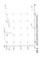
- FIG. 3is a graph showing the orientation of the point spread function of an imaging system using a single omnidirectional probe as a function of the position of the omnidirectional probe.
- FIG. 4is a graph showing the orientation of the point spread function of an imaging system using a single omnidirectional probe as a function of the position of the omnidirectional probe when it is not in the scan plane.
- FIG. 6is a schematic diagram illustrating the relative positions of probes showing, in addition, points A-A′, which have equal round trip distances and times.
- FIG. 7is a schematic diagram showing a possible fixture for positioning an omni-directional probe relative to the main (insonifying) probe.
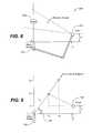
- FIG. 8is a schematic diagram showing a non-instrumented linkage for two probes.
- FIG. 9is a schematic diagram showing variables for computation of x and y positions from received echoes.
- FIG. 10 ais a phantom image taken with a standard Acuson 128 XP-10 with a 3.5 MHz transducer and harmonic processing.
- FIG. 10 bis the same phantom image as that shown in FIG. 10A and taken with the same XP-10, wherein the center 64 elements were obscured but external processing employed to show improved lateral resolution.
- the progressions of anechoic areas on the phantomare 8 mm diameter, 6 mm, 4 mm, 3 mm, and 2 mm.
- FIG. 11is an image of the same phantom produced by the same transducer as the images in FIGS. 10 a and 10 b , with the center obscured, but with substantial image processing over multiple scans. Note that even though the total aperture is only 19 mm that the 2 mm diameter anechoic areas are now visible. Lateral resolution could be greatly improved if the two parts of the transducer were physically separated and the phased delays reprogrammed for the resulting geometry.
- FIG. 12 ais a schematic perspective view showing an adjustable, extendable hand held two-aperture probe (especially adapted for use in cardiology US imaging). This view shows the probe in a partially extended configuration.
- FIG. 12 bis a side view in elevation thereof showing the probe in a collapsed configuration.
- FIG. 12 cshows the probe extended so as to place the heads at a maximum separation distance permitted under the probe design, and poised for pushing the separated probe apertures into a collapsed configuration.
- FIG. 12 dis a side view in elevation again showing the probe in a collapsed configuration, with adjustment means shown (i.e., as scroll wheel).
- FIG. 12 eis a detailed perspective view showing surface features at the gripping portion of the probe.
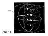
- FIG. 13is a 3D image highlighting the anechoic tubes of the ATS Model 539 phantom.
- a key element of the present inventionis that returned echoes in ultrasonography can be detected by a separate relatively non-directional receive transducer located away from the insonifying probe (transmit transducer), and the non-directional receive transducer can be placed in a different acoustic window from the insonifying probe.
- This probewill be called an omni-directional probe because it can be designed to be sensitive to a wide field of view.
- the entire two-dimensional imagecan be formed from the information received by the one omni. Additional copies of the image can be formed by additional omni-directional probes collecting data from the same set of insonifying pulses.
- FIG. 2in which there is shown the position of the omni-directional probe 100 relative to the position of the insonifying (main) probe 120 and the insonifying beam 130 .
- the position of the omni-directional probe relative to the beamis indicated by x 0 , y 0 and z 0 140 , where x 0 and y 0 are in the scan plane 150 scanned by the insonifying beam and z 0 is distance perpendicular to that plane.
- FIG. 3shows the orientation 200 of the psf as a function of the position of the omni probe.
- the insonifying probe (main probe)is located at the center group 220 on the bottom of the figure.
- the horizontal (x axis) 230 showngoes from ⁇ 40 mm to +40 mm.
- the vertical (y axis) 240goes from 0 to 80 mm depth.
- FIG. 4shows the orientation 300 of the psf as a function of the position of the omni probe if it is not in the scan plane.
- the horizontal (x axis) 310 shownagain goes from ⁇ 40 mm to +40 mm, but the vertical axis 320 is the z axis (distance away from the scan plane) and goes from 0 to 80 mm away from the scan plane.
- FIG. 5shows a plot of the same circular object 20 as in FIG. 1 , plotted, however, from data received by a single omni element.
- Other complete two dimensional reconstructionsmay be formed using data from additional omni elements, if desired.
- Specular reflectionis reduced using the omni probe compared to using the main probe for both insonification and detection. This is because all parts of a surface normal to the main beam are insonified with the same phase. When the phase is such that maximum echo is returned, all the echoes add to produce a specular echo. When the signals are normalized to accommodate the dynamic response of a particular display device, non-specular echoes will tend to drop out.
- points A-A′ 400which have equal round trip distances and times.
- the reconstructed imagewill get better as the angle between the main beam and the omni gets larger. However it is not necessary to focus a narrow beam on every element of tissue to be imaged as is true if the data is not stored and then processed before display.
- the lateral resolutioncan be reconstructed using a Wiener filter to be much better than the beam width if the noise spectrum is low enough. In one simulation of 2 circles of diameter 2.2 mm and 4.0 mm, both imaged well enough that the center was clear even though the beam width was 4.4 mm tapered from 1 to 0 by a cosine function.
- the Wiener filteris described in the next section.
- Another way to eliminate speckleis to obtain a good sample of it for estimates of the noise spectrum to then be used in the Wiener filter.
- Wiener filterTwo possibilities exist with regard to the Wiener filter.
- a Wiener filtercan be used separately on each image and then combine them.
- FIG. 7illustrates a simplified version of such a fixture, wherein fixed hinges allow movement of only x 0 and y 0 .
- Another methodis to have no mechanical connection between the omni probe and the main probe (except wires for signals and power). Instead, the omni probe can transmit a signal using radio frequencies, light, or a different frequency ultrasound to triangulation receivers mounted on the main probe or a separate platform.
- a third methodagain has no mechanical connection between the omni probe and main probe.
- the omni probe(or probes) can be attached to the patient with tape, and the ultrasonographer can manipulate the main probe to find the best image without regard to positioning the omni probe(s).
- a two-dimensional imagecan be formed separately from the echoes received from the omni probe and from the main probe.
- Standard multi-dimensional search techniquesthat could be used include gradient ascent, second order (Newton's method), simulated annealing, and genetic algorithms.
- a fifth variable, the angle of the psf which is necessary for deconvolution,is implied from the first four variables. Misregistration of the images can be caused by inaccurate estimation of any of the four variables, but good registration can be achieved by simply adjusting D which will tend to compensate for errors in estimates of the others.
- the four variablescan be estimated over several frames of information.
- the framescan be combined at high rate holding x 0 , y 0 , z 0 and D constant.
- a fourth method for determining the position of the omni probe(s)entails replacing the omni probe or probes with a “semi-omni probe” or probes. The reason for this is to increase the signal to noise ratio by restricting the sensitive region of the receive transducer to a plane rather than a hemisphere. Because of this restriction it is necessary to have a mechanical linkage to ensure that both the transmit and receive transducers are focused on the same plane.
- Two probescould be placed in any two acoustic windows. In the case of echocardiography, one would likely be in the normal parasternal window which typically gives the clearest view of the whole heart. A second window available in most patients is the apical view. Another window usually available is the subcostal. The two probes could even be placed on either side of the sternum or in parasternal windows in two intercostal spaces.
- One probecould be the standard phased array cardiac probe.
- the second (and third, etc.)would be used as receive only. Theoretically it could be omnidirectional, but that would necessarily provide lower signals and therefore low signal to noise ratios (S/N).
- S/Nsignal to noise ratios
- a better alternativeis to use a probe which is ground to be sensitive to a plane of scan but omnidirectional within that plane.
- a single piece of PZTwould work well, but to minimize the amount of new design required it is also possible to use a second probe head similar to the main probe and then use individual elements or small groups combined to act as single elements. The design goal is to use as many elements as possible to maximize signal to noise ratio while using few enough to minimize angle sensitivity.
- the two probes 610 , 620may be linked together with an articulating mechanical linkage, which ensures that the plane of scan of each probe includes the other, but the distance between them is unconstrained.
- a slave servomechanismis also possible, but the mechanical linkage will be described here.
- the procedureis to aim the main probe 620 at the target 630 (e.g., heart) and position the secondary probe 610 at a second window with maximum received signal strength.
- the main probebe positioned for a long axis view with the secondary probe over the apex of the heart. Some slight deviation of the long axis view may be necessary in order to maintain the secondary probe in its most sensitive spot.
- the secondary probewould now be held on the patient with a mechanical housing which allows a fan or rocking motion.
- the disadvantage of having two probes in fixed positions on the bodyis that the plane of scan must include these two points.
- the only degree of freedomis the angle at which the scan plane enters the patient's body.
- the 3D informationis obtained by rocking the main probe back and forth through a sufficient angle so that the entire heart is insonified.
- the secondary probealso rocks back and forth by virtue of the mechanical linage between the probes. The instantaneous angle of rocking must be monitored—perhaps by reference to a gyroscope mounted with the main probe.
- the rockingcould be actuated by the hand motion of the ultrasound technician, or it could be motorized for a more-uniform angle rate.
- the main probe and an array of omni probesare placed in adjacent intercostal spaces using a mechanism as shown in FIG. 12 .
- Computer softwarecould be provided such that the 2D slices would fill a 3D volume of voxels. After adjacent voxels are filled through interpolation, 3D information can be displayed as projections or as slices through the volume at arbitrary orientations.
- any tilt of the main probewill change the reference axes so that x and particularly y will change too.
- a pulseWhen a pulse is transmitted from the main probe it insonifies a sequence of tissues in the path of the beam.
- the returns from the tissueswill be received by both the main probe and the secondary, digitized and stored in the computer. Echoes from relatively proximate tissues will be different for the two probes, but echoes from mid- to far range will be similar. It is possible to use cross correlation to find similar small patches in the two stored returns. They will be similar except for the time delay relative to the launching of the pulse from the main probe.
- the time delaywill be related to the offsets x and y. Values for x and y cannot be determined from one set of time delays, but can be determined by solving a set of simultaneous equations from two detected similar returns. These could be different patches of the same pulse return or from returns from differently directed main pulses.
- tissue packet at ( x 1 y 1 )is received at time t 1m
- distance m 2sqrt( x 2 2 +y 2 2 ) t 1m
- x, y, and zcan be calculated by solving three simultaneous equations.
- the minimum E 2will indicate the minimum squared error estimate of (x, y).
- the minimum E 2will indicate the minimum squared error estimate of (x, y).
- the searchshould be conducted over the expected range of x and y to save time and to avoid spurious ambiguous minima.
- the minimum E 2will indicate the minimum squared error estimate of (x, y, z).
- the probes that have been described for imaging the heartwould work equally well for imaging abdominal organs and other parts of the body such as legs, arms, and neck.
- use of receive-only transducers in conjunction with a transmit/receive probewould work better for abdominal organs because the orientation of the probe set is not limited by the intercostal spaces formed by the ribs.
- the locations of the acoustic windows to the heartlimit the orientation of the probe to only a few orientations and it is necessary to rock the probe to gather three dimensional data
- the probescan be used on the abdomen in any orientation presently used. Therefore the probes can be used for real-time 2D scans to duplicate presently accepted procedures except with much higher lateral resolution.
- this application of the technologymay be as important as the application to cardiology (which was our original motivation).
- the same arraycould be partitioned into an active section plus one or more passive sections where all sections would be used for each pulse.
- the active section of elementswould be used in transmit as a sector scanner sending out beams in a sequence of angular paths.
- all elementswould be treated as independent relatively nondirectional receivers and their outputs would be combined to form a high resolution image by the methods taught in this patent.
- Cross-correlation image matchingto account for the variations in ultrasound speeds could be done separately for each receive element or for groups of elements for which the speed corrections would be nearly the same.
- a final class of probeswould involve putting a receive-only transducer or transducers on the end of a catheter to be inserted in an artery, vein, or urethra while a separated transmit transducer array is applied to the surface of the skin.
- the advantage of this approachis that the catheter could be positioned close to an organ of interest thereby reducing the total transit distance from the transmit transducer to the receive element and thus higher frequencies could be used for better resolution.
- the receive element(s) on the catheterwould not have to be steered as it (they) would be relatively omnidirectional.
- the inverse DFT or FFTis then used to obtain the image estimate s(n,m) from its spectrum.
- the Wiener filteris defined in terms of the following spectra:
- the Wiener filteris:
- G ⁇ ( u , v )H * ⁇ ( u , v ) ⁇ P S ⁇ ( u , v ) ⁇ H ⁇ ( u , v ) ⁇ 2 ⁇ P S ⁇ ( u , v ) + P n ⁇ ( u , v )
- the ratio P s /P ncan be interpreted as signal-to-noise ratio.
- the Wiener filterbecomes H ⁇ 1 (u,v),the inverse filter for the psf.
- the Wiener filtertends to 0 and blocks them out.
- P s (u,v)+P n (u,v)
- the right hand functionis easy to compute from the Fourier transform of the observed data. P n (u,v) is often assumed to be constant over (u,v). It is then subtracted from the total to yield P s (u,v).
- the psfcan be measured by observing a wire phantom in a tank using the ultrasound instrument.
- the Fourier transform of the psfcan then be stored for later use in the Wiener filter when examining patients.
- the Wiener filterwill have to be applied separately for several range zones and the resulting images will have to be pieced together to form one image for display.
- a useful compromisemight be to optimize the Wiener filter just for the range of the object of interest such as a coronary artery or valve. It will be necessary to store separate Wiener filters for each omni-directional probe and for the main probe when it is used as a receive transducer.
- LMS Filteringis used in the spatial domain rather than the frequency domain, and can be applied to the radial scan line data, the lateral data at each depth, or both together.
- Image sharpeningcan be accomplished by the use of unsharp masking. Because aperture blur is much more pronounced in the lateral dimension perpendicular to the insonifying beam) than in the radial dimension, it is necessary to perform unsharp masking in only one dimension. When using a sector scanner, this masking should be performed before scan conversion. When using a linear phased array, the unsharp masking should be performed on each data set of constant range. Unsharp masking consists of intentionally blurring an image, subtracting the result from the original image, multiplying the difference by an arbitrary factor, and adding this to the original image. In one dimension this is the same as blurring a line of data, subtracting it from the original line, and adding a multiple of the difference to the original line.
- phased array headscan also be used together so that both are active on the same scan.
- two (or more) phased array transducersWhen two (or more) phased array transducers are placed in the same scan plane, they can be programmed with delays such that they act as a single array with a gap in the array of transducer elements.
- the advantages of having a gap in the arrayinclude a) achieving the lateral resolution of a wide aperture without the expense of filling in acoustic elements through the gap, and b) the gap in the probe or between probes can be fitted over ribs or the sternum.
- the first advantageapplies equally to applications other than cardiac.
- the disadvantages of multiple active probesis that both the transmit and receive delays have to be recomputed for each new gap dimension and/or angular orientation of one probe relative to the others.
- FIG. 10 athere is illustrated the image 800 of an ATS Laboratories Model 539 phantom was imaged using an Acuson 128 XP-10 ultrasonic scanner with a 4V2c probe.
- FIG. 10 bthe same probe was used to image the phantom with its center 64 elements totally obscured by aluminum foil and electrical tape.
- the lateral resolution in the image 900is as good as the original although the image quality is degraded by speckle and other noise.
- FIG. 11shows an image 1000 of the same phantom produced by the same transducer with the center obscured, but with substantial image processing over multiple scans.
- FIGS. 12 a - eare various views showing an adjustable, extendable hand held two-aperture probe 1100 adapted for use in cardiology US imaging.
- This apparatusembodies the inventive concept of separating the insonifying probe 1110 (a transmit transducer) from the imaging elements 1120 (receiver transducer).
- This comfortable deviceincludes adjustment means 1130 , such as a scroll wheel, which selectively drives the elements either closer or further apart along either a medial telescoping portion 1140 or a medial insertable sleeve, and thereby provides a range of separation at predetermined distances.
- the gripping portion 1150provides easy access to the scroll wheel and places the user's hand in the functional position to minimize overuse injury.
- FIG. 12 ashows the probe in a partially extended configuration.
- FIG. 12 bshows the probe in a collapsed configuration.
- FIG. 12 cshows the probe extended so as to place the heads at a maximum separation distance permitted under the probe design.
- FIG. 12 dshows the probe in a collapsed configuration, with adjustment means shown.
- FIG. 12 eis a detailed perspective view showing surface features at the gripping portion of the probe.
- FIG. 13shows a three-dimensional display 1200 of the anechoic tubes of the Model 539 phantom. This 3D display was formed from 13 parallel slices produced with the same transducer with the center obscured. When the total aperture is increased it will be possible to display smaller anechoic tubes such as the coronary arteries.
- the processing involved for this displayis a combination of the techniques of the instant patent and those of co-pending U.S. patent application Ser. No. 11/532,013.
Landscapes
- Health & Medical Sciences (AREA)
- Life Sciences & Earth Sciences (AREA)
- Engineering & Computer Science (AREA)
- Physics & Mathematics (AREA)
- Pathology (AREA)
- Public Health (AREA)
- General Health & Medical Sciences (AREA)
- Biophysics (AREA)
- Veterinary Medicine (AREA)
- Biomedical Technology (AREA)
- Heart & Thoracic Surgery (AREA)
- Medical Informatics (AREA)
- Molecular Biology (AREA)
- Surgery (AREA)
- Animal Behavior & Ethology (AREA)
- Radiology & Medical Imaging (AREA)
- Nuclear Medicine, Radiotherapy & Molecular Imaging (AREA)
- Radar, Positioning & Navigation (AREA)
- Remote Sensing (AREA)
- Acoustics & Sound (AREA)
- Computer Networks & Wireless Communication (AREA)
- General Physics & Mathematics (AREA)
- Computer Vision & Pattern Recognition (AREA)
- Gynecology & Obstetrics (AREA)
- Artificial Intelligence (AREA)
- Physiology (AREA)
- Psychiatry (AREA)
- Signal Processing (AREA)
- Vascular Medicine (AREA)
- Ultra Sonic Daignosis Equipment (AREA)
Abstract
Description
This application is a continuation of U.S. patent application Ser. No. 11/865,501 filed Oct. 1, 2007, now U.S. Pat. No. 8,007,439; which application claims the benefit of U.S. Provisional Patent Applications No. 60/862,951, filed Oct. 25, 2006, and No. 60/940,261, filed May 25, 2007; all of which are incorporated by reference in their entirety herein.
1. Field of the Invention
The present invention relates generally to imaging techniques used in medicine, and more particularly to medical ultrasound, and still more particularly to an apparatus for producing ultrasonic images using multiple apertures.
2. Discussion of Related Art Including Information Disclosed Under 37 CFR §§1.97, 1.98
In conventional ultrasonic imaging, a focused beam of ultrasound energy is transmitted into body tissues to be examined and the returned echoes are detected and plotted to form an image. In echocardiography the beam is usually stepped in increments of angle from a center probe position, and the echoes are plotted along lines representing the paths of the transmitted beams. In abdominal ultrasonography the beam is usually stepped laterally, generating parallel beam paths, and the returned echoes are plotted along parallel lines representing these paths. The following description will relate to the angular scanning technique for echocardiography (commonly referred to as a sector scan). However, the same concept with modifications can be implemented in abdominal scanners.
The basic principles of conventional ultrasonic imaging are well described in the first chapter of Echocardiography, by Harvey Feigenbaum (Lippincott Williams & Wilkins, 5thed., Philadelphia, 1993). These will not be repeated here except as necessary to illustrate the differences between the conventional techniques and the present invention.
It is well known that the average velocity v of ultrasound in human tissue is about 1540 m/sec, the range in soft tissue being 1440 to 1670 m/sec (see for example P. N. T. Wells, Biomedical Ultrasonics, Academic Press, London, New York, San Francisco, 1977). Therefore, the depth of an impedance discontinuity generating an echo can be estimated as the round-trip time for the echo multiplied by v/2, and the amplitude is plotted at that depth along a line representing the path of the beam. After this has been done for all echoes along all beam paths, an image is formed, such as theimage 10 shown inFIG. 1 , in which a circle has been imaged. The gaps between the scan lines are typically filled in by interpolation. One of the earliest interpolation algorithms applied to echocardiography was described in U.S. Pat. No. 4,271,842, to Specht et al.
In order to insonify the body tissues, a beam formed either by a phased array or a shaped transducer is scanned over the tissues to be examined. Traditionally, the same transducer or array is used to detect the returning echoes. This design configuration lies at the heart of one of the most significant limitations in the use of ultrasonic imaging for medical purposes; namely, poor lateral resolution. Theoretically the lateral resolution could be improved by increasing the aperture of the ultrasonic probe, but the practical problems involved with aperture size increase have kept apertures small and lateral resolution large. Unquestionably, ultrasonic imaging has been very useful even with this limitation, but it could be more effective with better resolution.
In the practice of cardiology, for example, the limitation on single aperture size is dictated by the space between the ribs (the intercostal spaces). For scanners intended for abdominal and other use, the limitation on aperture size is not so obvious, but it is a serious limitation nevertheless. The problem is that it is difficult to keep the elements of a large aperture array in phase because the speed of ultrasound transmission varies with the type of tissue between the probe and the area of interest. According to the book by Wells (cited above), the speed varies up to plus or minus 10% within the soft tissues. When the aperture is kept small, the intervening tissue is, to a first order of approximation, all the same and any variation is ignored. When the size of the aperture is increased to improve the lateral resolution, the additional elements of a phased array may be out of phase and may actually degrade the image rather than improving it. The instant disclosure teaches methods to maintain all of the information from an extended phased array “in phase” and thus to achieve sought-after improved lateral resolution.
In the case of cardiology, it has long been thought that extending the phased array into a second or third intercostal space would improve the lateral resolution, but this idea has met with two problems. First, elements over the ribs have to be eliminated, leaving a sparsely filled array. New theory is necessary to steer the beam emanating from such an array. Second, the tissue speed variation described above, but not adequately addressed until this time, needs to be compensated. The same solution taught in this disclosure is equally applicable for multi-aperture cardiac scanning, or for extended sparsely populated apertures for scans on other parts of the body.
The present invention solves both the problem of using more than one intercostal space and the problem of accommodating unknown phase delays from using elements spread over a large sparse aperture. The solution involves separating the insonifying probe from the imaging elements. The separation can be a physical separation or simply a separation in concept wherein some of the elements of the array can be shared for the two functions.
A single omni-directional receive element (such as a receive transducer) can gather all of the information necessary to reproduce a two-dimensional section of the body. Each time a pulse of ultrasound energy is transmitted along a particular path, the signal received by the omnidirectional probe can be recorded into a line of memory. [The terms “omni-directional probe,” “omni probe” and/or “omni,” are used synonymously herein to mean an omnidirectional probe.] When this is done for all of the lines in a sector scan, the memory can be used to reconstruct the image. This can be accomplished in the same time as data is being collected for the next frame.
There are numerous advantages to this approach, and these comprise the objects and advantages of the present invention. They include, among others:
The dominance of specular reflections so prominent in reconstructing images by returns to the main probe is greatly attenuated.
More than one omnidirectional probe can be used. Each one can be used to reconstruct an entire sector image but with different point spread functions. These can be combined to produce an image with a sharper point spread function.
Compensations can be made for different delays in different paths through the tissue.
Many more scan lines can be reconstructed than the number of pulses generated by the main probe. This overcomes the traditional limit of the number of scan lines by the speed of ultrasound in tissue, tissue depth of interest, and the time allowed between frames, which is typically 1/30thsecond.
Artificial scan lines can be considered as overlapping, and each pixel on an output image can be imaged from information from more than one omni line of data. Therefore the output pixel can be averaged from multiple data, thus improving the signal-to-noise ratio.
Omnidirectional probes can be placed in multiple intercostal spaces, the suprasternal notch, the substernal window, multiple apertures along the abdomen and other parts of the body, and even on the end of a catheter. An advantage in using omnidirectional probes for catheter placement is that no steering is required of the probe.
Probes can be placed either on the image plane, off of it, or any combination. When placed away from the image plane, omni probe information can be used to narrow the thickness of the sector scanned.
There has thus been broadly outlined the more important features of the invention in order that the detailed description that follows may be better understood, and in order that the present contribution to the art may be better appreciated. Additional objects, advantages and novel features of the invention will be set forth in part in the description as follows, and in part will become apparent to those skilled in the art upon examination of the following. Furthermore, such objects, advantages and features may be learned by practice of the invention, or may be realized and attained by means of the instrumentalities and combinations particularly pointed out in the appended claims.
Still other objects and advantages of the present invention will become readily apparent to those skilled in this art from the following detailed description, which shows and describes only the preferred embodiments of the invention, simply by way of illustration of the best mode now contemplated of carrying out the invention. As will be realized, the invention is capable of modification in various obvious respects without departing from the invention. Accordingly, the drawings and description of the preferred embodiment are to be regarded as illustrative in nature, and not as restrictive.
A key element of the present invention is that returned echoes in ultrasonography can be detected by a separate relatively non-directional receive transducer located away from the insonifying probe (transmit transducer), and the non-directional receive transducer can be placed in a different acoustic window from the insonifying probe. This probe will be called an omni-directional probe because it can be designed to be sensitive to a wide field of view.
If the echoes detected at the omni probe are stored separately for every pulse from the insonifying transducer, it is surprising to note that the entire two-dimensional image can be formed from the information received by the one omni. Additional copies of the image can be formed by additional omni-directional probes collecting data from the same set of insonifying pulses.
A large amount of straightforward computation is required to plot the amplitude of echoes received from the omni. Referring now toFIG. 2 , in which there is shown the position of the omni-directional probe 100 relative to the position of the insonifying (main)probe 120 and theinsonifying beam 130. The position of the omni-directional probe relative to the beam is indicated by x0, y0andz 0140, where x0and y0are in thescan plane 150 scanned by the insonifying beam and z0is distance perpendicular to that plane. Instead of simply plotting the depth along the scan line d=t v/2 (where t is the round-trip time, it is now computed as that point d=sqrt(x^2+y^2) for which t v=d+sqrt((x-x0)^2+(y-y0)^ 2+z0^2).
This procedure will produce a sector scan image similar to that using the conventional technique except that the point spread function will be rotated.FIG. 3 shows theorientation 200 of the psf as a function of the position of the omni probe. A single point at x=0, y=70 mm, z=0 is the point being imaged, and the groups ofdots 210 each indicate the orientation of the psf if the omni-probe were placed at the location of the center of each group. The insonifying probe (main probe) is located at thecenter group 220 on the bottom of the figure. In this simulation the horizontal (x axis)230 shown goes from −40 mm to +40 mm. The vertical (y axis)240 goes from 0 to 80 mm depth.
Specular reflection is reduced using the omni probe compared to using the main probe for both insonification and detection. This is because all parts of a surface normal to the main beam are insonified with the same phase. When the phase is such that maximum echo is returned, all the echoes add to produce a specular echo. When the signals are normalized to accommodate the dynamic response of a particular display device, non-specular echoes will tend to drop out.
In contrast to this, and referring now toFIG. 6 , there is also shown the relative positions of probes, but there is also shown points A-A′400, which have equal round trip distances and times. Points A-A′ are on a surface normal to the bisector line a1=a2410, which also have equal round trip distances and times, are not insonified with the same phase, and do not all reflect equally. This attenuation of the specular reflection is particularly important when visualizing circular structures which frequently have surfaces normal to the main beam.
An algorithm to plot this data on a rectangular grid is: (a) for each point on the x,y grid, convert x,y to depth and angle; (b) then find closest angle k scanned by the insonifying beam; (c) if it is sufficiently close, then convert x,y to distance to the omni; (d) compute time t=(distance to insonifying beam+distance to omni)/v; and (e) plot amplitude recorded by the omni for the k scan at x,y.
However, more information is available and should be used. It is possible to use the same technique to plot additional scan lines which were not explicitly insonified by the insonifying probe. Because of the inherently wide beam width of medical ultrasonic probes, much tissue between intentional scan lines is also insonified and returns echoes. Making use of this information is particularly important when capturing motion (especially in echocardiography) because the number of pulses that can be generated is strictly limited by the speed of ultrasound in tissue and the scan repetition rate desired.
The reconstructed image will get better as the angle between the main beam and the omni gets larger. However it is not necessary to focus a narrow beam on every element of tissue to be imaged as is true if the data is not stored and then processed before display. The lateral resolution can be reconstructed using a Wiener filter to be much better than the beam width if the noise spectrum is low enough. In one simulation of 2 circles of diameter 2.2 mm and 4.0 mm, both imaged well enough that the center was clear even though the beam width was 4.4 mm tapered from 1 to 0 by a cosine function. The Wiener filter is described in the next section.
There are four main sources of noise in ultrasonic imaging: (1) blur due to array size not wide enough; (2) shot noise; (3) reverberation from big interfaces; and (4) speckle.
Multiple probes give independent measures of shot noise, but using closely spaced elements in the main probe (if it is a phased array) will not give independent noise for the other three sources. Adding one or more omni probes will change the look angle, which will thereby change the speckle pattern and the reverberation pattern. These can be averaged out to lower the noise power spectrum. The Wiener filter can then be employed to cancel the blur.
Another way to eliminate speckle is to obtain a good sample of it for estimates of the noise spectrum to then be used in the Wiener filter.
De-blurring and de-noising by these techniques using only an external omni probe or probes will make it possible to visualize small and moving objects such as the coronary arteries. In such a case medical personnel could assess the degree of opening in the lumen or patency of bypass grafts without resort to invasive catheterization techniques.
When combining more than one image such as one from the main probe and another from one or more omni probes for the purpose of averaging out the various sources of noise, it is necessary to compensate for the variation in ultrasound velocity through different paths. Experiments have shown that small unaccounted errors in path velocity will displace the reconstructed image in both horizontal and vertical positions. Cross correlation techniques should be used to find the displacement with one image taken as reference before addition or other combination of images.
Two possibilities exist with regard to the Wiener filter. In one, a Wiener filter can be used separately on each image and then combine them. Alternatively, one can first combine the images (yielding a more complex point spread function) and then employ Wiener filtering.
In order to perform the indicated computations, it is necessary to either measure or estimate the position (x0, y0, z0) of the omni relative to the main probe. Exact knowledge of these positions is not required because, as we have seen, the displacement of the image from the omni probe is also affected by the variation of the velocity of ultrasound in different types of tissue. For this reason it is necessary to use cross correlation or some other matching criterion to make a final correction of the position of the omni-generated image before combining with the reference image or images.
Determining the Position of the Omni Probe(s): There are many ways to determine the position of the omni probe. Referring now toFIG. 7 , one way is to provideapparatus 500 for pivotally and/or swivelingly mounting theomni probe 510 on afixture 520 attached to theinsonifying probe 530. The fixture preferably includes articulatedjoints 540 with sensors (not shown) to measure angles anddistances 550 of the links.FIG. 7 illustrates a simplified version of such a fixture, wherein fixed hinges allow movement of only x0and y0.
Another method is to have no mechanical connection between the omni probe and the main probe (except wires for signals and power). Instead, the omni probe can transmit a signal using radio frequencies, light, or a different frequency ultrasound to triangulation receivers mounted on the main probe or a separate platform.
A third method again has no mechanical connection between the omni probe and main probe. For this method the omni probe (or probes) can be attached to the patient with tape, and the ultrasonographer can manipulate the main probe to find the best image without regard to positioning the omni probe(s). As indicated inFIG. 4 , a two-dimensional image can be formed separately from the echoes received from the omni probe and from the main probe. By adjusting four variables (x0, y0, z0and D, the average difference in time for ultrasound to go through different tissue types instead of traveling though idealized tissue of constant ultrasound velocity), the images can be made to coincide. The four variables can be adjusted iteratively to maximize cross-correlation or another measure of similarity. Standard multi-dimensional search techniques that could be used include gradient ascent, second order (Newton's method), simulated annealing, and genetic algorithms. A fifth variable, the angle of the psf which is necessary for deconvolution, is implied from the first four variables. Misregistration of the images can be caused by inaccurate estimation of any of the four variables, but good registration can be achieved by simply adjusting D which will tend to compensate for errors in estimates of the others.
When the application requires the highest resolution compatible with capturing motion at a high frame rate, the four variables can be estimated over several frames of information. When the ultrasonographer has selected a good view angle, the frames can be combined at high rate holding x0, y0, z0and D constant.
When the application requires the highest possible resolution, data can be captured (perhaps with EKG gating to capture separate images at systole and diastole) and the multi-dimensional search to optimize matching can be done more accurately although not in real time. Two advantages of this approach is that different values of D can be found for systole and diastole, and that different psfs can be used for deconvolution at different depths in the image.
Determining the Position of the Omni Probe(s) Using Correlation of the Scan Line Data Rather than Complete 2D Sectors: A fourth method for determining the position of the omni probe(s) entails replacing the omni probe or probes with a “semi-omni probe” or probes. The reason for this is to increase the signal to noise ratio by restricting the sensitive region of the receive transducer to a plane rather than a hemisphere. Because of this restriction it is necessary to have a mechanical linkage to ensure that both the transmit and receive transducers are focused on the same plane.
Two probes could be placed in any two acoustic windows. In the case of echocardiography, one would likely be in the normal parasternal window which typically gives the clearest view of the whole heart. A second window available in most patients is the apical view. Another window usually available is the subcostal. The two probes could even be placed on either side of the sternum or in parasternal windows in two intercostal spaces.
One probe could be the standard phased array cardiac probe. The second (and third, etc.) would be used as receive only. Theoretically it could be omnidirectional, but that would necessarily provide lower signals and therefore low signal to noise ratios (S/N). A better alternative is to use a probe which is ground to be sensitive to a plane of scan but omnidirectional within that plane. A single piece of PZT would work well, but to minimize the amount of new design required it is also possible to use a second probe head similar to the main probe and then use individual elements or small groups combined to act as single elements. The design goal is to use as many elements as possible to maximize signal to noise ratio while using few enough to minimize angle sensitivity.
In this embodiment600 (seeFIG. 8 ), the twoprobes
The procedure is to aim themain probe 620 at the target630 (e.g., heart) and position thesecondary probe 610 at a second window with maximum received signal strength. One possibility is that the main probe be positioned for a long axis view with the secondary probe over the apex of the heart. Some slight deviation of the long axis view may be necessary in order to maintain the secondary probe in its most sensitive spot.
The secondary probe would now be held on the patient with a mechanical housing which allows a fan or rocking motion. The disadvantage of having two probes in fixed positions on the body is that the plane of scan must include these two points. The only degree of freedom is the angle at which the scan plane enters the patient's body. For a conventional 2D examination this is a severe limitation, but if the goal is to gather three-dimensional information, this is not a limitation. The 3D information is obtained by rocking the main probe back and forth through a sufficient angle so that the entire heart is insonified. The secondary probe also rocks back and forth by virtue of the mechanical linage between the probes. The instantaneous angle of rocking must be monitored—perhaps by reference to a gyroscope mounted with the main probe. The rocking could be actuated by the hand motion of the ultrasound technician, or it could be motorized for a more-uniform angle rate. In an alternative preferred embodiment (for echocardiography), the main probe and an array of omni probes are placed in adjacent intercostal spaces using a mechanism as shown inFIG. 12 .
Computer software could be provided such that the 2D slices would fill a 3D volume of voxels. After adjacent voxels are filled through interpolation, 3D information can be displayed as projections or as slices through the volume at arbitrary orientations.
The need for and one important use of the 3D information is covered in co-pending U.S. patent application Ser. No. 11/532,013, also by the present inventor, and which application is incorporated in its entirety by reference herein.
Yet another variation on this theme is to have the secondary transducer mechanically linked to the primary so that each plane of scan contains the other transducer (as above), but allow rotation of the main probe about its own axis. In this case the secondary probe would be allowed to move on the patient's body (properly prepared with ultrasound gel). It would have many elements, and an attached computer would scan them all to find those elements which have the strongest return signal.
Estimating Relative Probe Positions from Reflected Signals: For image reconstruction it is essential to know the position of the secondary probe (x, y) relative to the main probe. This has to be evaluated separately for each frame of data because of the motion of the patient, technician, and/or motorized angle actuator. Since the linkage will prevent any difference in position (z) perpendicular to the scan plane, only x and y need be assessed.
Note that any tilt of the main probe will change the reference axes so that x and particularly y will change too.
When a pulse is transmitted from the main probe it insonifies a sequence of tissues in the path of the beam. The returns from the tissues will be received by both the main probe and the secondary, digitized and stored in the computer. Echoes from relatively proximate tissues will be different for the two probes, but echoes from mid- to far range will be similar. It is possible to use cross correlation to find similar small patches in the two stored returns. They will be similar except for the time delay relative to the launching of the pulse from the main probe. The time delay will be related to the offsets x and y. Values for x and y cannot be determined from one set of time delays, but can be determined by solving a set of simultaneous equations from two detected similar returns. These could be different patches of the same pulse return or from returns from differently directed main pulses.
Referring now toFIG. 9 , if themain probe 700 transmits at angle 90°-α 710 relative to its centerline and an identifiable packet of returns occurs at time t1mat the main probe and at time t.sub.1s at the secondary (omni)probe 720, then:
tissue packet at (x1y1) is received at timet1m, and distancem1=sqrt(x12+y12)
tissue packet at (x2,y2) is received at timet2m, and distancem2=sqrt(x22+y22)
t1m, corresponds to time of two trips of distancem1
t1ms=2m1, wheres=speed of ultrasound in same units asm=approx.1.54×106mm/sec
t1ss=m1+sqrt((x1-x)2+(y1-y)2).
Similarly,t2ms=2m2
t2ss=m2+sqrt((x2-x)2+(y2-y)2)
(t1ss−0.5t1m)=(x1-x)2+(y1-y)2
(t2ss−0.5t2ms)2=(x2-x)2+(y2-y)2 (1)
Since Xj, y15x2, y2and the times are known, one can solve the last two simultaneous equations for x and y.
Similarly, if a z offset between the two probes is allowed, x, y, and z can be calculated by solving three simultaneous equations.
Many more measurements from packet pairs are available. One could make a measurement on several or every scan line (angle) as measured from the main probe. Then we would have many equations in 2 unknowns which can be used to make more-accurate estimations of the 2 unknowns. Since these are nonlinear equations, a search technique can be utilized. One way to accomplish this is to compute error squared over a grid of (x, y) points using the equation:
The minimum E2will indicate the minimum squared error estimate of (x, y). The search
The minimum E2will indicate the minimum squared error estimate of (x, y). The search should be conducted over the expected range of x and y to save time and to avoid spurious ambiguous minima.
When the z component of the relative position is not constrained to be zero, the comparable error squared equation is:
The minimum E2will indicate the minimum squared error estimate of (x, y, z).
If the speed of sound on the return path to the secondary (omni) transducer is different from s due to different types of tissues being traversed, the values of x and y (and z if used) will be different from the geometric values. However, use of these values in the image reconstruction algorithm will automatically compensate for the different speeds.
Obviously, the probes that have been described for imaging the heart would work equally well for imaging abdominal organs and other parts of the body such as legs, arms, and neck. In fact, use of receive-only transducers in conjunction with a transmit/receive probe would work better for abdominal organs because the orientation of the probe set is not limited by the intercostal spaces formed by the ribs. Whereas the locations of the acoustic windows to the heart limit the orientation of the probe to only a few orientations and it is necessary to rock the probe to gather three dimensional data, the probes can be used on the abdomen in any orientation presently used. Therefore the probes can be used for real-time 2D scans to duplicate presently accepted procedures except with much higher lateral resolution. In fact, this application of the technology may be as important as the application to cardiology (which was our original motivation).
For abdominal scanning it is not necessary to have an elaborate spacing adjustment between the active transmit/receive elements and the receive-only elements. In fact they could all be mounted together in one rigid probe, either as a linear array or an array with known curvature. Some prior art wide linear arrays exist which insonify tissue by using a small subset of the total number of elements to transmit and receive a beam perpendicular to the array. Then another partially overlapping subset of elements is used to transmit and receive another line parallel to the first one, and so on until an entire scan is completed.
However, the same array could be partitioned into an active section plus one or more passive sections where all sections would be used for each pulse. The active section of elements would be used in transmit as a sector scanner sending out beams in a sequence of angular paths. On receive, all elements would be treated as independent relatively nondirectional receivers and their outputs would be combined to form a high resolution image by the methods taught in this patent. Cross-correlation image matching to account for the variations in ultrasound speeds could be done separately for each receive element or for groups of elements for which the speed corrections would be nearly the same.
The concept of mounting the active and receive-only elements on a rigid structure eliminates the necessity for articulating and instrumenting the spacing between elements thus making practical combined probes to be used for trans-esophageal (TEE), trans-vaginal, and trans-rectal imaging.
A final class of probes would involve putting a receive-only transducer or transducers on the end of a catheter to be inserted in an artery, vein, or urethra while a separated transmit transducer array is applied to the surface of the skin. The advantage of this approach is that the catheter could be positioned close to an organ of interest thereby reducing the total transit distance from the transmit transducer to the receive element and thus higher frequencies could be used for better resolution. The receive element(s) on the catheter would not have to be steered as it (they) would be relatively omnidirectional.
The Wiener Filter: The Wiener filter itself is not new, but since it is important for the de-convolution step it will be described briefly here in the context of the present invention. The Wiener filter is the mean squared error optimal stationary linear filter for images degraded by additive noise and blurring. Wiener filters are usually applied in the frequency domain. Given a degraded image I(n.m.), one takes the discrete Fourier Transform (DFT) or the Fast Fourier Transform (FFT) to obtain I(u,v). The true image spectrum is estimated by taking the product of I(u,v) with the Wiener filter G(u,v):
Ŝ=G(u,v)I(u,v)
Ŝ=G(u,v)I(u,v)
The inverse DFT or FFT is then used to obtain the image estimate s(n,m) from its spectrum. The Wiener filter is defined in terms of the following spectra:
(a) H(u,v)—Fourier transform of the point spread function (psf);
(b) Ps(u,v)—Power spectrum of the signal process, obtained by taking the Fourier transform of the signal autocorrelation;
(c) Pn(u,v)—Power spectrum of the noise process, obtained by taking the Fourier transform of the noise autocorrelation;
The Wiener filter is:
The ratio Ps/Pncan be interpreted as signal-to-noise ratio. At frequencies with high signal to noise ratio, the Wiener filter becomes H−1(u,v),the inverse filter for the psf. At frequencies for which the signal to noise ratio is low, the Wiener filter tends to 0 and blocks them out.
Ps(u,v)+Pn(u,v)=|I(u,v)|2. The right hand function is easy to compute from the Fourier transform of the observed data. Pn(u,v) is often assumed to be constant over (u,v). It is then subtracted from the total to yield Ps(u,v).
The psf can be measured by observing a wire phantom in a tank using the ultrasound instrument. The Fourier transform of the psf can then be stored for later use in the Wiener filter when examining patients.
Because the psf is not constant as a function of range, the Wiener filter will have to be applied separately for several range zones and the resulting images will have to be pieced together to form one image for display. A useful compromise might be to optimize the Wiener filter just for the range of the object of interest such as a coronary artery or valve. It will be necessary to store separate Wiener filters for each omni-directional probe and for the main probe when it is used as a receive transducer.
An alternative to the Wiener Filter for deconvolution is the least mean square (LMS) adaptive filter described in co-pending U.S. patent application Ser. No. 11/532,013. LMS Filtering is used in the spatial domain rather than the frequency domain, and can be applied to the radial scan line data, the lateral data at each depth, or both together.
Image sharpening can be accomplished by the use of unsharp masking. Because aperture blur is much more pronounced in the lateral dimension perpendicular to the insonifying beam) than in the radial dimension, it is necessary to perform unsharp masking in only one dimension. When using a sector scanner, this masking should be performed before scan conversion. When using a linear phased array, the unsharp masking should be performed on each data set of constant range. Unsharp masking consists of intentionally blurring an image, subtracting the result from the original image, multiplying the difference by an arbitrary factor, and adding this to the original image. In one dimension this is the same as blurring a line of data, subtracting it from the original line, and adding a multiple of the difference to the original line.
Multiple Active Transducers—Two Alternative Approaches: It is possible to use more than one active transducer placed at multiple acoustic windows in order to achieve the same goals of increased lateral resolution and noise suppression. A practical method of providing multiple omni probes is to use a second phased array head in a second acoustic window and then treating each element or group of elements of the second phased array as a separate omni. With this configuration of probes it would be possible to switch the functions of the two probe heads on alternate scans thereby generating images with different speckle patterns which can be averaged out.
Multiple phased array heads can also be used together so that both are active on the same scan. When two (or more) phased array transducers are placed in the same scan plane, they can be programmed with delays such that they act as a single array with a gap in the array of transducer elements. The advantages of having a gap in the array include a) achieving the lateral resolution of a wide aperture without the expense of filling in acoustic elements through the gap, and b) the gap in the probe or between probes can be fitted over ribs or the sternum. The first advantage applies equally to applications other than cardiac. The disadvantages of multiple active probes is that both the transmit and receive delays have to be recomputed for each new gap dimension and/or angular orientation of one probe relative to the others.
An active probe with a gap has been demonstrated to produce lateral resolution as good as the probe without the gap. This implies that larger gaps will achieve higher resolution since lateral resolution is determined primarily by the overall aperture. Referring now toFIG. 10 a, there is illustrated theimage 800 of an ATS Laboratories Model 539 phantom was imaged using an Acuson 128 XP-10 ultrasonic scanner with a 4V2c probe. InFIG. 10 b, the same probe was used to image the phantom with its center 64 elements totally obscured by aluminum foil and electrical tape. As can be seen, the lateral resolution in theimage 900 is as good as the original although the image quality is degraded by speckle and other noise.
Having fully described several embodiments of the present invention, many other equivalents and alternative embodiments will be apparent to those skilled in the art. These and other equivalents and alternatives are intended to be included within the scope of the present invention.
Claims (19)
1. A method of determining a position of a receive transducer relative to an insonifying transducer, the method comprising the steps of:
transmitting an ultrasound pulse from a first transmit transducer located on a first array;
receiving and storing a first set of echo returns with transducers located on the first array;
receiving and storing a second set of echo returns on a first receive transducer located on a second array;
identifying a first patch of the first set of echo returns that is similar to a second patch of the second set of echo returns; and
solving simultaneous equations from the similar first and second patches to determine a position of the first receive transducer relative to the first transmit transducer.
2. The method ofclaim 1 , wherein the solving step further comprises solving two simultaneous equations from the similar first and second patches to determine the position of the first receive transducer relative to the first transmit transducer in two dimensions within a constrained scan plane.
3. The method ofclaim 1 wherein the step of identifying the first patch of the first set of echoes that is similar to the second patch of the second set of echoes further comprises evaluating said similarity using cross-correlation.
4. The method ofclaim 1 , further comprising:
determining a first time delay between a time of transmitting the ultrasound pulse and receiving the first patch of the first set of echo returns; and
determining a second time delay between a time of transmitting the ultrasound pulse and receiving the second patch of the second set of echo returns;
wherein said first time delay and said second time delay are used as known quantities in solving two simultaneous equations.
5. The method ofclaim 1 , further comprising identifying a third patch of echoes from the first set or the second set, the third patch being similar to the first patch or the second patch.
6. The method ofclaim 5 , further comprising solving three simultaneous equations to determine the position of the first receive transducer relative to the transmit transducer in three dimensions.
7. The method ofclaim 6 , further comprising the step of finding a minimum of an error function to determine the relative position of the first receive transducer relative to the transmit transducer, wherein the position of the first receive transducer relative to the transmit transducer is determined in three dimensions.
8. The method ofclaim 1 , further comprising the step of finding a minimum of an error function to determine the relative position of the first receive transducer relative to the transmit transducer.
9. The method ofclaim 8 , wherein the position of the first receive transducer relative to the transmit transducer is determined in two dimensions.
10. The method ofclaim 1 , wherein at least one element in the second array is omni-directional in a plane of scan.
11. The method ofclaim 1 , wherein the first array is located on a first probe and the second array is located on a second probe joined to the first probe by a mechanical linkage.
12. The method ofclaim 11 , wherein mechanical linkage is articulatable.
13. The method ofclaim 12 , wherein mechanical linkage comprises a telescoping portion.
14. The method ofclaim 1 , wherein the second array is configured to only receive echoes.
15. A method of ultrasound imaging, comprising:
insonifying a target tissue with an ultrasound pulse from a transmit transducer;
detecting and recording echo returns from the ultrasound pulse with the transmit transducer and with a receive transducer;
identifying a first patch of echo returns detected by the transmit transducer that is similar to a second patch of echo returns detected by the receive transducer;
solving a set of simultaneous equations from the first and second patches to determine a location of the transmit transducer in relation to the receive transducer; and
reconstructing an ultrasound image based on the location of the transmit transducer in relation to the receive transducer and the average speed of ultrasound in the target tissue.
16. The method ofclaim 15 wherein the reconstructing the ultrasound image step further comprises reconstructing scan lines as lines on a reconstructed image.
17. The method ofclaim 16 further comprising image processing to fill in gaps between scan lines.
18. The method ofclaim 15 wherein the receive transducer is angled differently than the transmit transducer.
19. The method ofclaim 15 wherein the step of identifying the first patch of echo returns detected by the transmit transducer that is similar to the second patch of echo returns detected by the receive transducer comprises using cross-correlation.
Priority Applications (7)
| Application Number | Priority Date | Filing Date | Title |
|---|---|---|---|
| US13/215,966US8277383B2 (en) | 2006-10-25 | 2011-08-23 | Method and apparatus to produce ultrasonic images using multiple apertures |
| US13/632,929US8684936B2 (en) | 2006-10-25 | 2012-10-01 | Method and apparatus to produce ultrasonic images using multiple apertures |
| US14/157,257US9072495B2 (en) | 2006-10-25 | 2014-01-16 | Method and apparatus to produce ultrasonic images using multiple apertures |
| US14/754,422US9420994B2 (en) | 2006-10-25 | 2015-06-29 | Method and apparatus to produce ultrasonic images using multiple apertures |
| US15/240,884US10130333B2 (en) | 2006-10-25 | 2016-08-18 | Method and apparatus to produce ultrasonic images using multiple apertures |
| US16/196,889US11096662B2 (en) | 2006-10-25 | 2018-11-20 | Method and apparatus to produce ultrasonic images using multiple apertures |
| US17/406,931US20210378633A1 (en) | 2006-10-25 | 2021-08-19 | Method and apparatus to produce ultrasonic images using multiple apertures |
Applications Claiming Priority (4)
| Application Number | Priority Date | Filing Date | Title |
|---|---|---|---|
| US86295106P | 2006-10-25 | 2006-10-25 | |
| US94026107P | 2007-05-25 | 2007-05-25 | |
| US11/865,501US8007439B2 (en) | 2006-10-25 | 2007-10-01 | Method and apparatus to produce ultrasonic images using multiple apertures |
| US13/215,966US8277383B2 (en) | 2006-10-25 | 2011-08-23 | Method and apparatus to produce ultrasonic images using multiple apertures |
Related Parent Applications (1)
| Application Number | Title | Priority Date | Filing Date |
|---|---|---|---|
| US11/865,501ContinuationUS8007439B2 (en) | 2006-02-06 | 2007-10-01 | Method and apparatus to produce ultrasonic images using multiple apertures |
Related Child Applications (1)
| Application Number | Title | Priority Date | Filing Date |
|---|---|---|---|
| US13/632,929ContinuationUS8684936B2 (en) | 2006-10-25 | 2012-10-01 | Method and apparatus to produce ultrasonic images using multiple apertures |
Publications (2)
| Publication Number | Publication Date |
|---|---|
| US20110306885A1 US20110306885A1 (en) | 2011-12-15 |
| US8277383B2true US8277383B2 (en) | 2012-10-02 |
Family
ID=39325221
Family Applications (8)
| Application Number | Title | Priority Date | Filing Date |
|---|---|---|---|
| US11/865,501Active2030-06-29US8007439B2 (en) | 2006-02-06 | 2007-10-01 | Method and apparatus to produce ultrasonic images using multiple apertures |
| US13/215,966ActiveUS8277383B2 (en) | 2006-10-25 | 2011-08-23 | Method and apparatus to produce ultrasonic images using multiple apertures |
| US13/632,929ActiveUS8684936B2 (en) | 2006-10-25 | 2012-10-01 | Method and apparatus to produce ultrasonic images using multiple apertures |
| US14/157,257ActiveUS9072495B2 (en) | 2006-10-25 | 2014-01-16 | Method and apparatus to produce ultrasonic images using multiple apertures |
| US14/754,422ActiveUS9420994B2 (en) | 2006-10-25 | 2015-06-29 | Method and apparatus to produce ultrasonic images using multiple apertures |
| US15/240,884ActiveUS10130333B2 (en) | 2006-10-25 | 2016-08-18 | Method and apparatus to produce ultrasonic images using multiple apertures |
| US16/196,889Active2028-01-05US11096662B2 (en) | 2006-10-25 | 2018-11-20 | Method and apparatus to produce ultrasonic images using multiple apertures |
| US17/406,931AbandonedUS20210378633A1 (en) | 2006-10-25 | 2021-08-19 | Method and apparatus to produce ultrasonic images using multiple apertures |
Family Applications Before (1)
| Application Number | Title | Priority Date | Filing Date |
|---|---|---|---|
| US11/865,501Active2030-06-29US8007439B2 (en) | 2006-02-06 | 2007-10-01 | Method and apparatus to produce ultrasonic images using multiple apertures |
Family Applications After (6)
| Application Number | Title | Priority Date | Filing Date |
|---|---|---|---|
| US13/632,929ActiveUS8684936B2 (en) | 2006-10-25 | 2012-10-01 | Method and apparatus to produce ultrasonic images using multiple apertures |
| US14/157,257ActiveUS9072495B2 (en) | 2006-10-25 | 2014-01-16 | Method and apparatus to produce ultrasonic images using multiple apertures |
| US14/754,422ActiveUS9420994B2 (en) | 2006-10-25 | 2015-06-29 | Method and apparatus to produce ultrasonic images using multiple apertures |
| US15/240,884ActiveUS10130333B2 (en) | 2006-10-25 | 2016-08-18 | Method and apparatus to produce ultrasonic images using multiple apertures |
| US16/196,889Active2028-01-05US11096662B2 (en) | 2006-10-25 | 2018-11-20 | Method and apparatus to produce ultrasonic images using multiple apertures |
| US17/406,931AbandonedUS20210378633A1 (en) | 2006-10-25 | 2021-08-19 | Method and apparatus to produce ultrasonic images using multiple apertures |
Country Status (3)
| Country | Link |
|---|---|
| US (8) | US8007439B2 (en) |
| EP (1) | EP2088932B1 (en) |
| WO (1) | WO2008051639A2 (en) |
Cited By (18)
| Publication number | Priority date | Publication date | Assignee | Title |
|---|---|---|---|---|
| US8684936B2 (en) | 2006-10-25 | 2014-04-01 | Maui Imaging, Inc. | Method and apparatus to produce ultrasonic images using multiple apertures |
| US9192355B2 (en) | 2006-02-06 | 2015-11-24 | Maui Imaging, Inc. | Multiple aperture ultrasound array alignment fixture |
| US9220478B2 (en) | 2010-04-14 | 2015-12-29 | Maui Imaging, Inc. | Concave ultrasound transducers and 3D arrays |
| US9265484B2 (en) | 2011-12-29 | 2016-02-23 | Maui Imaging, Inc. | M-mode ultrasound imaging of arbitrary paths |
| US9339256B2 (en) | 2007-10-01 | 2016-05-17 | Maui Imaging, Inc. | Determining material stiffness using multiple aperture ultrasound |
| US9510806B2 (en) | 2013-03-13 | 2016-12-06 | Maui Imaging, Inc. | Alignment of ultrasound transducer arrays and multiple aperture probe assembly |
| US9526475B2 (en) | 2006-09-14 | 2016-12-27 | Maui Imaging, Inc. | Point source transmission and speed-of-sound correction using multi-aperture ultrasound imaging |
| US9572549B2 (en) | 2012-08-10 | 2017-02-21 | Maui Imaging, Inc. | Calibration of multiple aperture ultrasound probes |
| US9668714B2 (en) | 2010-04-14 | 2017-06-06 | Maui Imaging, Inc. | Systems and methods for improving ultrasound image quality by applying weighting factors |
| US9883848B2 (en) | 2013-09-13 | 2018-02-06 | Maui Imaging, Inc. | Ultrasound imaging using apparent point-source transmit transducer |
| US9986969B2 (en) | 2012-09-06 | 2018-06-05 | Maui Imaging, Inc. | Ultrasound imaging system memory architecture |
| US10201326B2 (en) | 2013-07-02 | 2019-02-12 | Samsung Electronics Co., Ltd. | Ultrasonic diagnostic apparatus and method of operating the same |
| US10206662B2 (en) | 2009-04-14 | 2019-02-19 | Maui Imaging, Inc. | Calibration of ultrasound probes |
| US10226234B2 (en) | 2011-12-01 | 2019-03-12 | Maui Imaging, Inc. | Motion detection using ping-based and multiple aperture doppler ultrasound |
| US10401493B2 (en) | 2014-08-18 | 2019-09-03 | Maui Imaging, Inc. | Network-based ultrasound imaging system |
| US10856846B2 (en) | 2016-01-27 | 2020-12-08 | Maui Imaging, Inc. | Ultrasound imaging with sparse array probes |
| US12167209B2 (en) | 2012-09-06 | 2024-12-10 | Maui Imaging, Inc. | Ultrasound imaging system memory architecture |
| US12190627B2 (en) | 2015-03-30 | 2025-01-07 | Maui Imaging, Inc. | Ultrasound imaging systems and methods for detecting object motion |
Families Citing this family (25)
| Publication number | Priority date | Publication date | Assignee | Title |
|---|---|---|---|---|
| WO2007092054A2 (en)* | 2006-02-06 | 2007-08-16 | Specht Donald F | Method and apparatus to visualize the coronary arteries using ultrasound |
| CN101516271B (en)* | 2006-10-03 | 2011-08-17 | 奥林巴斯医疗株式会社 | Ultrasonic image processing device and ultrasonic image diagnostic device |
| US9788813B2 (en) | 2010-10-13 | 2017-10-17 | Maui Imaging, Inc. | Multiple aperture probe internal apparatus and cable assemblies |
| RU2507535C2 (en)* | 2008-06-05 | 2014-02-20 | Конинклейке Филипс Электроникс Н.В. | Extended field of view ultrasonic imaging with two dimensional array probe |
| US8876720B2 (en)* | 2008-08-05 | 2014-11-04 | Guardsman Scientific, Inc. | Peripheral ultrasound device providing pivotal adjustment of an imaging mechanism about two axes |
| US8348847B2 (en)* | 2008-08-05 | 2013-01-08 | Guardsman Scientific, Inc. | System and method for managing a patient |
| US20110270089A1 (en)* | 2008-08-05 | 2011-11-03 | Guardsman Scientific, Inc. | System and method for managing a patient |
| WO2010017445A2 (en)* | 2008-08-08 | 2010-02-11 | Maui Imaging, Inc. | Imaging with multiple aperture medical ultrasound and synchronization of add-on systems |
| EP2419023A4 (en)* | 2009-04-14 | 2013-01-16 | Maui Imaging Inc | Universal multiple aperture medical ultrasound probe |
| US20100286527A1 (en)* | 2009-05-08 | 2010-11-11 | Penrith Corporation | Ultrasound system with multi-head wireless probe |
| JP5835903B2 (en)* | 2011-02-03 | 2015-12-24 | 株式会社東芝 | Ultrasonic diagnostic equipment |
| EP2756805B1 (en)* | 2011-09-15 | 2017-11-08 | Hitachi, Ltd. | Ultrasound imaging apparatus |
| CN103049925B (en)* | 2012-12-29 | 2016-01-20 | 汕头市超声仪器研究所有限公司 | Based on C scan image or the D scan image disposal route of phased array |
| KR101555271B1 (en)* | 2013-11-29 | 2015-09-24 | 알피니언메디칼시스템 주식회사 | Method And Apparatus for Reconstitution Ultrasound Image |
| EP3126872B1 (en)* | 2014-03-31 | 2021-05-12 | Koninklijke Philips N.V. | System and method for acoustic imaging with coherent compounding using intercostal spaces |
| US10743837B2 (en)* | 2014-08-04 | 2020-08-18 | Delphinus Medical Technologies, Inc. | Ultrasound waveform tomography method and system |
| KR20160090102A (en)* | 2015-01-21 | 2016-07-29 | 삼성전자주식회사 | An ultrasonic imaging apparatus, an ultrasonic probe apparatus, a signal processing apparatus and a method for controlling the ultrasonic imaging apparatus |
| EP3247281B1 (en) | 2015-01-23 | 2020-12-02 | The University of North Carolina at Chapel Hill | Apparatuses, systems, and methods for preclinical ultrasound imaging of subjects |
| CN106859695B (en)* | 2017-01-13 | 2020-04-14 | 飞依诺科技(苏州)有限公司 | Q-frame T-aperture composite emission imaging method and system applied to ultrasonic probe |
| US11334974B2 (en) | 2017-08-16 | 2022-05-17 | Koninklijke Philips N.V. | Systems, methods, and apparatuses for image artifact cancellation |
| CN110974293B (en)* | 2019-12-11 | 2021-05-18 | 华中科技大学 | A synthetic aperture imaging method based on C-type probe |
| US11998393B2 (en) | 2020-10-20 | 2024-06-04 | GE Precision Healthcare LLC | System and method of signal processing for ultrasound arrays with mechanically adjustable transducer shapes |
| EP4236811A4 (en)* | 2020-11-02 | 2024-10-09 | Maui Imaging, Inc. | SYSTEMS AND METHODS FOR ENHANCING ULTRASOUND IMAGE QUALITY |
| CN115835822A (en)* | 2021-06-07 | 2023-03-21 | 京东方科技集团股份有限公司 | Ultrasonic imaging apparatus and ultrasonic imaging method |
| US20230121319A1 (en)* | 2021-10-15 | 2023-04-20 | Tzvi Neuman | Integrated Bedside Echocardiogram Monitor |
Citations (165)
| Publication number | Priority date | Publication date | Assignee | Title |
|---|---|---|---|---|
| US4271842A (en) | 1978-03-03 | 1981-06-09 | Smith Kline Instruments, Inc. | Apparatus and method for providing multiple ultrasonic sector image displays |
| US4333474A (en) | 1978-02-06 | 1982-06-08 | New York Institute Of Technology | Ultrasonic imaging system |
| US4339952A (en) | 1979-04-26 | 1982-07-20 | Ontario Cancer Institute | Cylindrical transducer ultrasonic scanner |
| US4501279A (en) | 1981-09-18 | 1985-02-26 | Tokyo Shibaura Denki Kabushiki Kaisha | Ultrasonic blood flow sensing apparatus |
| US4682497A (en) | 1985-03-04 | 1987-07-28 | Kabushiki Kaisha Toshiba | Ultrasonic imaging apparatus |
| US4893628A (en) | 1988-04-04 | 1990-01-16 | Bjorn Angelsen | Dual element ultrasonic transducer probe for combined imaging of tissue structures and blood flow in real time |
| WO1992018054A1 (en) | 1991-04-22 | 1992-10-29 | Interspec, Inc. | Ultrasonic probe assembly |
| US5355888A (en) | 1992-11-12 | 1994-10-18 | Massachusetts Institute Of Technology | High resolution phased array echo imager |
| US5409010A (en) | 1992-05-19 | 1995-04-25 | Board Of Regents Of The University Of Washington | Vector doppler medical devices for blood velocity studies |
| US5442462A (en) | 1992-06-10 | 1995-08-15 | D.V.P. Technologies Ltd. | Apparatus and method for smoothing images |
| US5503152A (en) | 1994-09-28 | 1996-04-02 | Tetrad Corporation | Ultrasonic transducer assembly and method for three-dimensional imaging |
| US5515853A (en) | 1995-03-28 | 1996-05-14 | Sonometrics Corporation | Three-dimensional digital ultrasound tracking system |
| US5522393A (en) | 1994-05-24 | 1996-06-04 | Duke University | Multi-dimensional real-time ultrasonic blood flow imaging apparatus and method |
| US5675550A (en) | 1995-06-08 | 1997-10-07 | Ekhaus; Ira B. | Reduced wavenumber synthetic aperture |
| US5798459A (en) | 1995-05-12 | 1998-08-25 | Japan As Represented By President Of Hokkaido University | Subject identification method, apparatus and system |
| US5876342A (en) | 1997-06-30 | 1999-03-02 | Siemens Medical Systems, Inc. | System and method for 3-D ultrasound imaging and motion estimation |
| US5916169A (en) | 1995-06-07 | 1999-06-29 | Acuson Corporation | Phased array transducer design and method for manufacture thereof |
| US5964707A (en) | 1993-11-29 | 1999-10-12 | Life Imaging Systems Inc. | Three-dimensional imaging system |
| US6014473A (en) | 1996-02-29 | 2000-01-11 | Acuson Corporation | Multiple ultrasound image registration system, method and transducer |
| US6056693A (en) | 1999-08-16 | 2000-05-02 | General Electric Company | Ultrasound imaging with synthetic transmit focusing |
| US6122538A (en) | 1997-01-16 | 2000-09-19 | Acuson Corporation | Motion--Monitoring method and system for medical devices |
| US6148095A (en) | 1997-09-08 | 2000-11-14 | University Of Iowa Research Foundation | Apparatus and method for determining three-dimensional representations of tortuous vessels |
| US6166853A (en) | 1997-01-09 | 2000-12-26 | The University Of Connecticut | Method and apparatus for three-dimensional deconvolution of optical microscope images |
| US6193665B1 (en) | 1998-12-31 | 2001-02-27 | General Electric Company | Doppler angle unfolding in ultrasound color flow and Doppler |
| US6196739B1 (en) | 1997-07-15 | 2001-03-06 | Silverbrook Research Pty Ltd | Paper guide system in a print on demand digital camera system |
| US6246901B1 (en) | 1999-05-05 | 2001-06-12 | David A. Benaron | Detecting, localizing, and targeting internal sites in vivo using optical contrast agents |
| JP2001245884A (en) | 1999-12-27 | 2001-09-11 | Ge Yokogawa Medical Systems Ltd | Ultrasonic imaging apparatus |
| US6304684B1 (en) | 2000-02-15 | 2001-10-16 | Cyberecord, Inc. | Information processing system and method of using same |
| US6324453B1 (en) | 1998-12-31 | 2001-11-27 | Automotive Technologies International, Inc. | Methods for determining the identification and position of and monitoring objects in a vehicle |
| US20020035864A1 (en) | 1997-12-31 | 2002-03-28 | Yoav Paltieli | Calibration method and apparatus for calibrating position sensors on scanning transducers |
| US6394955B1 (en) | 1999-02-01 | 2002-05-28 | Siemens Aktiengesellschaft | Device attachable to a therapeutic head for adjustably holding an ultrasound transducer, and therapeutic head in combination with such a device |
| US20020087071A1 (en) | 2000-09-15 | 2002-07-04 | Institut Fur Diagnostikforschung Gmbh | Process for graphic visualization and diagnosis of thrombi by means of nuclear spin tomography with use of particulate contrast media |
| US20020111568A1 (en) | 2001-02-12 | 2002-08-15 | Shmuel Bukshpan | Method for phased array ultrasonic transmission |
| US6449821B1 (en) | 1997-09-23 | 2002-09-17 | Koninklijke Philips Electronics, N.V. | Method of constructing segmented connections for multiple elevation transducers |
| US6468216B1 (en) | 2000-08-24 | 2002-10-22 | Kininklijke Philips Electronics N.V. | Ultrasonic diagnostic imaging of the coronary arteries |
| US20030028111A1 (en) | 1998-09-18 | 2003-02-06 | The University Of Washington | Noise-free real time ultrasonic imaging of a treatment site undergoing high intensity focused ultrasound therapy |
| US6517484B1 (en) | 2000-02-28 | 2003-02-11 | Wilk Patent Development Corporation | Ultrasonic imaging system and associated method |
| US20030040669A1 (en) | 2001-01-09 | 2003-02-27 | Michael Grass | Method of imaging the blood flow in a vascular tree |
| US6614560B1 (en) | 1997-07-15 | 2003-09-02 | Silverbrook Research Pty Ltd | Integrated camera circuit including image sensor, image processing, and printer drive circuits |
| US6652461B1 (en) | 1999-04-15 | 2003-11-25 | F.R.A.Y Project Ltd. | Ultrasound device for three-dimensional imaging of internal structure of a body part |
| US20030228053A1 (en) | 2002-05-03 | 2003-12-11 | Creatv Microtech, Inc. | Apparatus and method for three-dimensional image reconstruction |
| US6690816B2 (en) | 2000-04-07 | 2004-02-10 | The University Of North Carolina At Chapel Hill | Systems and methods for tubular object processing |
| US6695778B2 (en) | 2002-07-03 | 2004-02-24 | Aitech, Inc. | Methods and systems for construction of ultrasound images |
| US6702745B1 (en) | 1999-01-21 | 2004-03-09 | David Smythe | 3D/4D ultrasound imaging system |
| US6728567B2 (en) | 1998-03-20 | 2004-04-27 | Barbara Ann Karmanos Cancer Institute | Method and apparatus for high-resolution detection and characterization of medical pathologies |
| US6752762B1 (en) | 1999-01-21 | 2004-06-22 | Acuson Corporation | Method and apparatus for ultrasound contrast imaging |
| US20040122322A1 (en) | 2002-12-18 | 2004-06-24 | Barbara Ann Karmanos Cancer Institute | Electret acoustic transducer array for computerized ultrasound risk evaluation system |
| US20040122313A1 (en) | 2002-12-18 | 2004-06-24 | Barbara Ann Karmanos Cancer Institute | Methods and systems for using reference images in acoustic image processing |
| US6755787B2 (en) | 1998-06-02 | 2004-06-29 | Acuson Corporation | Medical diagnostic ultrasound system and method for versatile processing |
| US20040127793A1 (en) | 1998-03-09 | 2004-07-01 | Mendlein John D. | Methods and devices for improving ultrasonic measurements using multiple angle interrogation |
| US20040138565A1 (en) | 2002-11-28 | 2004-07-15 | Andrea Trucco | Method and apparatus for ultrasonic imaging using acoustic beamforming |
| US6780152B2 (en) | 2002-06-26 | 2004-08-24 | Acuson Corporation | Method and apparatus for ultrasound imaging of the heart |
| US6790182B2 (en) | 2000-09-05 | 2004-09-14 | Koninklijke Philips Electronics N.V. | Ultrasound system and ultrasound diagnostic apparatus for imaging scatterers in a medium |
| US20050004449A1 (en) | 2003-05-20 | 2005-01-06 | Matthias Mitschke | Method for marker-less navigation in preoperative 3D images using an intraoperatively acquired 3D C-arm image |
| US6843770B2 (en) | 2002-06-26 | 2005-01-18 | Acuson Corporation | Compound tuning method and system |
| US20050054910A1 (en) | 2003-07-14 | 2005-03-10 | Sunnybrook And Women's College Health Sciences Centre | Optical image-based position tracking for magnetic resonance imaging applications |
| US20050053305A1 (en) | 2003-09-10 | 2005-03-10 | Yadong Li | Systems and methods for implementing a speckle reduction filter |
| US20050090743A1 (en) | 2003-10-14 | 2005-04-28 | Olympus Corporation | Ultrasonic diagnostic apparatus |
| US20050113694A1 (en) | 2003-11-21 | 2005-05-26 | Haugen Geir U. | Ultrasound probe distributed beamformer |
| US20050147297A1 (en) | 2002-03-04 | 2005-07-07 | Mclaughlin Robert A. | Unsupervised data segmentation |
| US6932767B2 (en) | 2003-03-20 | 2005-08-23 | Siemens Medical Solutions Usa, Inc. | Diagnostic medical ultrasound system having a pipes and filters architecture |
| US20050281447A1 (en) | 2004-03-02 | 2005-12-22 | Romain Moreau-Gobard | System and method for detecting the aortic valve using a model-based segmentation technique |
| US20050288588A1 (en) | 2004-06-25 | 2005-12-29 | Peter Weber | Real-time 3D ultrasonic imaging apparatus and method |
| US20060062447A1 (en) | 2004-09-09 | 2006-03-23 | Daniel Rinck | Method for simple geometric visualization of tubular anatomical structures |
| US20060074315A1 (en) | 2004-10-04 | 2006-04-06 | Jianming Liang | Medical diagnostic ultrasound characterization of cardiac motion |
| US20060079778A1 (en) | 2004-10-07 | 2006-04-13 | Zonare Medical Systems, Inc. | Ultrasound imaging system parameter optimization via fuzzy logic |
| US20060079782A1 (en) | 2004-08-31 | 2006-04-13 | University Of Washington | Ultrasonic technique for assessing wall vibrations in stenosed blood vessels |
| US20060079759A1 (en) | 2004-10-13 | 2006-04-13 | Regis Vaillant | Method and apparatus for registering 3D models of anatomical regions of a heart and a tracking system with projection images of an interventional fluoroscopic system |
| US7033320B2 (en) | 2003-08-05 | 2006-04-25 | Siemens Medical Solutions Usa, Inc. | Extended volume ultrasound data acquisition |
| US7087023B2 (en) | 2003-02-14 | 2006-08-08 | Sensant Corporation | Microfabricated ultrasonic transducers with bias polarity beam profile control and method of operating the same |
| WO2006114735A1 (en) | 2005-04-25 | 2006-11-02 | Koninklijke Philips Electronics, N.V. | Method and apparatus for continuous imaging by ultrasound transducer system |
| US20070016044A1 (en) | 2003-01-14 | 2007-01-18 | University Of Virginia Patent Foundation | Ultrasonic transducer drive |
| US20070016022A1 (en) | 2003-01-14 | 2007-01-18 | University Of Virginia Patent Foundation | Ultrasound imaging beam-former apparatus and method |
| US20070036414A1 (en) | 2005-08-15 | 2007-02-15 | Siemens Corporate Research Inc | Method for database guided simultaneous multi slice object detection in three dimensional volumetric data |
| US20070055155A1 (en) | 2005-08-17 | 2007-03-08 | Neil Owen | Method and system to synchronize acoustic therapy with ultrasound imaging |
| US20070078345A1 (en) | 2005-09-30 | 2007-04-05 | Siemens Medical Solutions Usa, Inc. | Flexible ultrasound transducer array |
| US7221867B2 (en) | 1997-07-15 | 2007-05-22 | Silverbrook Research Pty Ltd | Device for image capture and processing |
| US7231072B2 (en) | 2002-02-27 | 2007-06-12 | Konica Corporation | Image processing method and image converting apparatus |
| US20070167752A1 (en) | 2005-12-07 | 2007-07-19 | Siemens Medical Solutions Usa, Inc. | Ultrasound imaging transducer array for synthetic aperture |
| US7269299B2 (en) | 2003-10-10 | 2007-09-11 | Orbimage Si Opco, Inc. | Image warp |
| US20070232914A1 (en) | 2005-12-07 | 2007-10-04 | Siemens Corporate Research, Inc. | System and Method For Adaptive Spatial Compounding For Ultrasound Imaging |
| US20070238999A1 (en) | 2006-02-06 | 2007-10-11 | Specht Donald F | Method and apparatus to visualize the coronary arteries using ultrasound |
| US20070242567A1 (en) | 2005-12-07 | 2007-10-18 | Daft Christopher M | Multi-dimensional CMUT array with integrated beamformation |
| US7313053B2 (en) | 2003-03-06 | 2007-12-25 | General Electric Company | Method and apparatus for controlling scanning of mosaic sensor array |
| US7366704B2 (en) | 2001-06-28 | 2008-04-29 | Waters Investments, Limited | System and method for deconvoluting the effect of topography on scanning probe microscopy measurements |
| US20080103393A1 (en) | 2006-10-25 | 2008-05-01 | Specht Donald F | Method and apparatus to produce ultrasonic images using multiple apertures |
| US20080114249A1 (en) | 2006-11-10 | 2008-05-15 | Penrith Corporation | Transducer array imaging system |
| US20080114255A1 (en) | 2006-11-10 | 2008-05-15 | Penrith Corporation | Transducer array imaging system |
| US20080110261A1 (en) | 2006-11-10 | 2008-05-15 | Penrith Corporation | Transducer array imaging system |
| US20080125659A1 (en) | 2006-11-28 | 2008-05-29 | Siemens Medical Solutions Usa, Inc. | Helical acoustic array for medical ultrasound |
| US7402136B2 (en) | 2003-01-15 | 2008-07-22 | University Of Virginia Patent Foundation | Efficient ultrasound system for two-dimensional C-scan imaging and related method thereof |
| US20080181479A1 (en) | 2002-06-07 | 2008-07-31 | Fuxing Yang | System and method for cardiac imaging |
| US20080188750A1 (en) | 2007-02-05 | 2008-08-07 | Penrith Corporation | Automated movement detection with audio and visual information |
| US7410469B1 (en) | 1999-05-21 | 2008-08-12 | Exogen, Inc. | Apparatus and method for ultrasonically and electromagnetically treating tissue |
| US20080194959A1 (en) | 2004-06-04 | 2008-08-14 | Shih-Ping Wang | Breast Ultrasound Scanning Promoting Patient Comfort and Improved Imaging Near Chest Wall |
| US20080194958A1 (en) | 2005-08-11 | 2008-08-14 | Medison, Co., Ltd | Method of Compounding and Ultrasound Image |
| US20080194957A1 (en) | 2007-02-14 | 2008-08-14 | Ralph Thomas Hoctor | Method and Apparatus for Generating an Ultrasound Image of Moving Objects Using Deformable Models |
| US7415880B2 (en) | 2002-07-17 | 2008-08-26 | Agfa Ntd Gmbh | Method for determining the sound velocity in a basic material, particularly for measuring the thickness of a wall |
| US20080208061A1 (en) | 2007-02-23 | 2008-08-28 | General Electric Company | Methods and systems for spatial compounding in a handheld ultrasound device |
| US20080242996A1 (en) | 2007-03-30 | 2008-10-02 | General Electric Company | Method and apparatus for measuring flow in multi-dimensional ultrasound |
| US20080255452A1 (en) | 2004-09-29 | 2008-10-16 | Koninklijke Philips Electronics, N.V. | Methods and Apparatus For Performing Enhanced Ultrasound Diagnostic Breast Imaging |
| US7443765B2 (en) | 2003-03-06 | 2008-10-28 | General Electric Company | Reconfigurable linear sensor arrays for reduced channel count |
| US20080269613A1 (en) | 2004-04-26 | 2008-10-30 | Summers Douglas G | Versatile Breast Ultrasound Scanning |
| US7447535B2 (en) | 2003-08-04 | 2008-11-04 | Koninklijke Philips Electronics N.V. | Mapping the coronary arteries on a sphere |
| US20080275344A1 (en) | 2007-05-04 | 2008-11-06 | Barbara Ann Karmanos Cancer Institute | Method and Apparatus for Categorizing Breast Density and Assessing Cancer Risk Utilizing Acoustic Parameters |
| US20080285819A1 (en) | 2006-08-30 | 2008-11-20 | The Trustees Of Columbia University In The City Of New York | Systems and method for composite elastography and wave imaging |
| US20080294045A1 (en) | 2003-11-21 | 2008-11-27 | Becky Ellington | Three Dimensional Ultrasonic Imaging Using Mechanical Probes with Beam Scanning Reversal |
| US20080294050A1 (en) | 2004-07-08 | 2008-11-27 | Ryuichi Shinomura | Ultrasonic Imaging Apparatus |
| US20080306386A1 (en) | 2007-06-05 | 2008-12-11 | Tatsuro Baba | Ultrasonic diagnostic apparatus and method of measuring velocity with ultrasonic waves |
| US20080306382A1 (en) | 2007-06-05 | 2008-12-11 | Siemens Medical Solutions Usa, Inc. | Adaptive clinical marker preservation in spatial compound ultrasound imaging |
| US7466848B2 (en) | 2002-12-13 | 2008-12-16 | Rutgers, The State University Of New Jersey | Method and apparatus for automatically detecting breast lesions and tumors in images |
| US7469096B2 (en) | 1997-07-15 | 2008-12-23 | Silverbrook Research Pty Ltd | Platen unit for a disposable camera having a printer |
| US20080319317A1 (en) | 2006-03-31 | 2008-12-25 | Naohisa Kamiyama | Ultrasonic diagnostic apparatus and method of controlling the same |
| US7474778B2 (en) | 2002-03-12 | 2009-01-06 | Hitachi Medical Corporation | Ultrasonograph |
| US20090010459A1 (en) | 2006-11-28 | 2009-01-08 | Garbini Lex J | Multi-twisted acoustic array for medical ultrasound |
| US20090018445A1 (en) | 2007-06-20 | 2009-01-15 | Perception Raisonnement Action En Medecine | Ultrasonic bone motion tracking system |
| US20090016163A1 (en) | 2006-03-01 | 2009-01-15 | Koninklijke Philips Electronics, N.V. | Linear array ultrasound transducer with microbeamformer |
| US20090024039A1 (en) | 2006-05-02 | 2009-01-22 | U-Systems, Inc. | Handheld volumetric ultrasound scanning device |
| US7481577B2 (en) | 2003-06-23 | 2009-01-27 | Siemens Medical Solutions Usa, Inc. | Ultrasound transducer fault measurement method and system |
| US20090036780A1 (en) | 2007-08-03 | 2009-02-05 | Innoscion, Llc | Wired and Wireless Remotely Controlled Ultrasonic Transducer and Imaging Apparatus |
| US20090043206A1 (en) | 2007-08-06 | 2009-02-12 | Farhad Towfiq | System and method for three-dimensional ultrasound imaging |
| US7491171B2 (en) | 2004-10-06 | 2009-02-17 | Guided Therapy Systems, L.L.C. | Method and system for treating acne and sebaceous glands |
| US20090048519A1 (en) | 2007-08-16 | 2009-02-19 | The University Of Virginia Patent Foundation | Hybrid Dual Layer Diagnostic Ultrasound Transducer Array |
| US7497830B2 (en) | 2003-11-21 | 2009-03-03 | Koninklijke Philips Electronics N.V. | Three dimensional ultrasonic imaging using mechanical probes with beam scanning reversal |
| US7497828B1 (en) | 1992-01-10 | 2009-03-03 | Wilk Ultrasound Of Canada, Inc. | Ultrasonic medical device and associated method |
| US20090069692A1 (en) | 2006-05-12 | 2009-03-12 | Koninklijke Philips Electronics, N.V. | Ultrasonic Synthetic Transmit Focusing With a Multiline Beamformer |
| US20090069686A1 (en) | 2007-09-11 | 2009-03-12 | Siemens Medical Solutions Usa, Inc. | Piezoelectric and CMUT layered ultrasound transducer array |
| US20090069681A1 (en) | 2007-09-12 | 2009-03-12 | Sonosite, Inc. | System and method for spatial compounding using phased arrays |
| US7510529B2 (en) | 2002-09-18 | 2009-03-31 | Zonare Medical Systems, Inc. | Ultrasound reconstruction unit |
| US7514851B2 (en) | 2005-07-13 | 2009-04-07 | Siemens Medical Solutions Usa, Inc. | Curved capacitive membrane ultrasound transducer array |
| US7549962B2 (en) | 1998-11-19 | 2009-06-23 | Siemens Medical Solutions Usa, Inc. | Diagnostic medical ultrasound systems and transducers utilizing micro-mechanical components |
| US20090182237A1 (en) | 2005-07-26 | 2009-07-16 | Angelsen Bjorn A J | Dual Frequency Band Ultrasound Transducer Arrays |
| US7574026B2 (en) | 2003-02-12 | 2009-08-11 | Koninklijke Philips Electronics N.V. | Method for the 3d modeling of a tubular structure |
| US20090208080A1 (en) | 2005-07-18 | 2009-08-20 | Vicente Grau | Method and computer program for spatial compounding of images |
| US7625343B2 (en) | 2005-07-01 | 2009-12-01 | Scimed Life Systems, Inc. | Concave phased array imaging catheter |
| US20090306510A1 (en) | 2005-06-17 | 2009-12-10 | Kunio Hashiba | Ultrasound Imaging Apparatus |
| US7637869B2 (en) | 2003-06-30 | 2009-12-29 | Koninklijke Philips Electronics N.V. | Two-dimensional transducer arrays for improved field of view |
| US20100016725A1 (en) | 2006-12-20 | 2010-01-21 | Koninklijke Philips Electronics N.V. | Multi-beam transmit isolation |
| US7674228B2 (en) | 2004-03-01 | 2010-03-09 | Sunnybrook And Women's College Health Sciences Centre | System and method for ECG-triggered retrospective color flow ultrasound imaging |
| US7699776B2 (en) | 2002-03-08 | 2010-04-20 | University Of Virginia Patent Foundation | Intuitive ultrasonic imaging system and related method thereof |
| US20100121193A1 (en) | 2007-04-24 | 2010-05-13 | Panasonic Corporation | Ultrasonsographic device |
| US20100121196A1 (en) | 1996-06-28 | 2010-05-13 | Sonosite, Inc. | Ultrasonic Signal Processor for a Hand Held Ultrasonic Diagnostic Instrument |
| US7722541B2 (en) | 2004-12-10 | 2010-05-25 | Siemens Medical Solutions Usa, Inc. | Multiple receive beams for rapid acquisition |
| US7744532B2 (en) | 2004-03-31 | 2010-06-29 | Siemens Medical Solutions Usa, Inc. | Coherence factor adaptive ultrasound imaging methods and systems |
| US20100168578A1 (en) | 2007-06-12 | 2010-07-01 | University Of Virginia Patent Foundation | System and Method for Combined ECG-Echo for Cardiac Diagnosis |
| US20100217124A1 (en) | 2006-06-27 | 2010-08-26 | Koninklijke Philips Electronics, N.V. | Ultrasound imaging system and method using multiline acquisition with high frame rate |
| US7787680B2 (en) | 2006-03-10 | 2010-08-31 | Medison Co., Ltd. | System and method for processing an image |
| US7785260B2 (en) | 2001-12-12 | 2010-08-31 | Hitachi Medical Corporation | Ultrasonograph |
| US7806828B2 (en) | 2002-02-05 | 2010-10-05 | Inceptio Medical Technologies, Lc | Multiplanar ultrasonic vascular sensor assembly and apparatus for movably affixing a sensor assembly to a body |
| US20100256488A1 (en) | 2007-09-27 | 2010-10-07 | University Of Southern California | High frequency ultrasonic convex array transducers and tissue imaging |
| US20100262013A1 (en) | 2009-04-14 | 2010-10-14 | Smith David M | Universal Multiple Aperture Medical Ultrasound Probe |
| US20100268503A1 (en) | 2009-04-14 | 2010-10-21 | Specht Donald F | Multiple Aperture Ultrasound Array Alignment Fixture |
| US7819810B2 (en) | 2002-02-05 | 2010-10-26 | Inceptio Medical Technologies, Lc | Multiplanar ultrasonic vascular sensor assembly, system and methods employing same, apparatus for movably affixing a sensor assembly to a body and associated methods |
| US7824337B2 (en) | 2005-12-27 | 2010-11-02 | Kabushiki Kaisha Toshiba | Ultrasonic image processing apparatus and control program for ultrasonic image processing apparatus |
| US7833163B2 (en) | 2003-12-10 | 2010-11-16 | Siemens Medical Solutions Usa, Inc. | Steering angle varied pattern for ultrasound imaging with a two-dimensional array |
| US7837624B1 (en) | 1998-11-20 | 2010-11-23 | Siemens Medical Solutions Usa, Inc. | Medical diagnostic ultrasound imaging methods for extended field of view |
| US7846097B2 (en) | 2003-02-20 | 2010-12-07 | Siemens Medical Solutions Usa, Inc. | Measuring transducer movement methods and systems for multi-dimensional ultrasound imaging |
| US7850613B2 (en) | 2003-05-30 | 2010-12-14 | Orison Corporation | Apparatus and method for three dimensional ultrasound breast imaging |
| US7876945B2 (en) | 2003-11-12 | 2011-01-25 | Valtion Teknillinen Tutkimuskeskus | Method for processing slice images |
| US7887486B2 (en) | 2003-07-25 | 2011-02-15 | Siemens Medical Solutions Usa, Inc. | Adaptive grating lobe suppression in ultrasound imaging |
| US20110178400A1 (en) | 2008-08-08 | 2011-07-21 | Maui Imaging, Inc. | Imaging with multiple aperture medical ultrasound and synchronization of add-on systems |
| US20110201933A1 (en) | 2006-09-14 | 2011-08-18 | Specht Donald F | Point source transmission and speed-of-sound correction using multi-aperture ultrasound imaging |
| US20120057428A1 (en) | 2009-04-14 | 2012-03-08 | Specht Donald F | Calibration of ultrasound probes |
| US20120095343A1 (en) | 2010-04-14 | 2012-04-19 | Smith David M | Concave Ultrasound Transducers and 3D Arrays |
| US20120095347A1 (en) | 2010-10-13 | 2012-04-19 | Adam Sharon L | Multiple Aperture Probe Internal Apparatus and Cable Assemblies |
Family Cites Families (293)
| Publication number | Priority date | Publication date | Assignee | Title |
|---|---|---|---|---|
| US3174286A (en) | 1963-06-27 | 1965-03-23 | Gen Motors Corp | Master cylinder |
| JPS4911189A (en) | 1972-05-29 | 1974-01-31 | ||
| US3895381A (en) | 1973-02-21 | 1975-07-15 | Winston E Kock | Synthetic aperture imaging systems |
| AT343265B (en) | 1973-08-16 | 1978-05-26 | Siemens Ag | DEVICE FOR MEASURING THE SPEED OF MEDIA IN PARTICULAR IN CABLES |
| JPS5444375B2 (en) | 1974-02-12 | 1979-12-25 | ||
| US4072922A (en) | 1975-11-13 | 1978-02-07 | Seiscom Delta Inc. | Method for seismic exploration for enhanced results in simulated cylindrical or plane waves |
| US4105018A (en) | 1976-02-02 | 1978-08-08 | University Of Utah | Acoustic examination, material characterization and imaging of the internal structure of a body by measurement of the time-of-flight of acoustic energy therethrough |
| US4097835A (en) | 1976-09-20 | 1978-06-27 | Sri International | Dual transducer arrangement for ultrasonic imaging system |
| US4055988A (en) | 1976-12-09 | 1977-11-01 | J. B. Engineering And Sales Company, Inc. | Alignment control apparatus for a turntable used in an ultrasonic testing system |
| JPS5444375A (en) | 1977-09-14 | 1979-04-07 | Oki Electric Ind Co Ltd | Ultrasonic wave reflection system |
| US4180792A (en) | 1978-03-09 | 1979-12-25 | General Electric Company | Transmit-receive transducer array and ultrasonic imaging system |
| JPS55103839A (en) | 1979-02-03 | 1980-08-08 | Fujitsu Ltd | Ultrasonic diagnosis apparatus |
| US4259733A (en) | 1979-05-14 | 1981-03-31 | Seiscom Delta, Inc. | Multi-dimensional seismic imaging |
| US4265126A (en) | 1979-06-15 | 1981-05-05 | General Electric Company | Measurement of true blood velocity by an ultrasound system |
| US4327738A (en) | 1979-10-19 | 1982-05-04 | Green Philip S | Endoscopic method & apparatus including ultrasonic B-scan imaging |
| JPS56103327A (en) | 1980-01-21 | 1981-08-18 | Hitachi Ltd | Ultrasonic image pickup apparatus |
| US4325257A (en) | 1980-02-20 | 1982-04-20 | Kino Gordon S | Real-time digital, synthetic-focus, acoustic imaging system |
| JPS5731848A (en) | 1980-08-01 | 1982-02-20 | Fujitsu Ltd | Ultrasonic diagnostic device |
| JPS6013109B2 (en) | 1980-09-17 | 1985-04-05 | 建設基礎エンジニアリング株式会社 | PC steel fixing device with unloading mechanism |
| JPS58223059A (en) | 1982-06-21 | 1983-12-24 | Toshiba Corp | Ultrasonic flaw detector |
| US4452084A (en) | 1982-10-25 | 1984-06-05 | Sri International | Inherent delay line ultrasonic transducer and systems |
| JPS59101143A (en) | 1982-12-02 | 1984-06-11 | 富士通株式会社 | Ultrasonic measurement or processing device |
| JPH064074B2 (en) | 1983-02-14 | 1994-01-19 | 株式会社日立製作所 | Ultrasonic diagnostic device and sound velocity measuring method using the same |
| JPS59174151A (en) | 1983-03-25 | 1984-10-02 | 横河メディカルシステム株式会社 | Ultrasonic image apparatus |
| US5141738A (en) | 1983-04-15 | 1992-08-25 | Schering Aktiengesellschaft | Ultrasonic contrast medium comprising gas bubbles and solid lipophilic surfactant-containing microparticles and use thereof |
| JPS6013109U (en) | 1983-07-07 | 1985-01-29 | アロカ株式会社 | Ultrasound diagnostic equipment |
| US4604697A (en) | 1983-08-05 | 1986-08-05 | Interspec, Inc. | Body imaging using vectorial addition of acoustic reflection to achieve effect of scanning beam continuously focused in range |
| JPS6068836A (en) | 1983-09-24 | 1985-04-19 | 株式会社島津製作所 | Ultrasonic diagnostic apparatus |
| US4539847A (en) | 1984-01-03 | 1985-09-10 | Texaco Inc. | Acoustic method and apparatus for measuring thickness of a coating layer on a substrate |
| JPS60150735A (en) | 1984-01-18 | 1985-08-08 | 株式会社東芝 | Ultrasound diagnostic equipment |
| US4662222A (en) | 1984-12-21 | 1987-05-05 | Johnson Steven A | Apparatus and method for acoustic imaging using inverse scattering techniques |
| US4781199A (en) | 1985-01-07 | 1988-11-01 | Kabushiki Kaisha Toshiba | System and method for measuring sound velocity of internal tissue in an object being investigated |
| US4669482A (en) | 1985-10-28 | 1987-06-02 | Board Of Regents, The University Of Texas System | Pulse echo method and apparatus for sound velocity estimation in vivo |
| US4817434A (en) | 1985-11-19 | 1989-04-04 | Forrest Anderson | Device for imaging three dimensions using simultaneous multiple beam formation |
| US4831601A (en) | 1986-10-31 | 1989-05-16 | Siemens Aktiengesellschaft | Apparatus for transmitting and receiving ultrasonic signals |
| FR2607631B1 (en) | 1986-11-28 | 1989-02-17 | Thomson Cgr | PROBE FOR ULTRASONIC APPARATUS HAVING A CONCEIVED ARRANGEMENT OF PIEZOELECTRIC ELEMENTS |
| JPS63216539A (en) | 1987-03-05 | 1988-09-08 | テルモ株式会社 | Apparatus for continuously measuring relative change of heart rate output quantity |
| US4893284A (en) | 1988-05-27 | 1990-01-09 | General Electric Company | Calibration of phased array ultrasound probe |
| US5197475A (en) | 1988-08-10 | 1993-03-30 | The Board Of Regents, The University Of Texas System | Method and apparatus for analyzing material properties using ultrasound |
| JP2777197B2 (en) | 1989-06-13 | 1998-07-16 | 株式会社東芝 | Ultrasound diagnostic equipment |
| JPH03126443A (en) | 1989-10-11 | 1991-05-29 | Matsushita Electric Ind Co Ltd | Ultrasonic probe |
| US5050588A (en) | 1990-02-08 | 1991-09-24 | Richard Grey | High energy ultrasonic lens assembly with mounting facets |
| JP2849159B2 (en) | 1990-05-11 | 1999-01-20 | 淑 中山 | Ultrasound diagnostic equipment |
| JPH0467856A (en) | 1990-07-09 | 1992-03-03 | Yokogawa Medical Syst Ltd | Ultrasonic imager by bistatic transmission/reception |
| JP3015527B2 (en) | 1991-08-14 | 2000-03-06 | 株式会社東芝 | Ultrasound diagnostic equipment |
| JPH0467856U (en) | 1990-10-25 | 1992-06-16 | ||
| US5161536A (en) | 1991-03-22 | 1992-11-10 | Catheter Technology | Ultrasonic position indicating apparatus and methods |
| US5230339A (en) | 1991-06-13 | 1993-07-27 | Array Tech, Inc. | Performance evaluation of ultrasonic examination equipment |
| US5349960A (en) | 1991-10-01 | 1994-09-27 | Olympus Optical Co., Ltd. | Ultrasonic diagnosis apparatus |
| US5704361A (en) | 1991-11-08 | 1998-01-06 | Mayo Foundation For Medical Education And Research | Volumetric image ultrasound transducer underfluid catheter system |
| US5278757A (en) | 1991-11-15 | 1994-01-11 | The Trustees Of The University Of Pennsylvania | Synthetic aperture ultrasonic imaging system using a minimum or reduced redundancy phased array |
| JP3043873B2 (en) | 1991-11-29 | 2000-05-22 | フクダ電子株式会社 | Ultrasonic aperture synthesis system |
| US5269309A (en) | 1991-12-11 | 1993-12-14 | Fort J Robert | Synthetic aperture ultrasound imaging system |
| US5226019A (en) | 1992-01-10 | 1993-07-06 | Amoco Corporation | Method of geophysical exploration |
| US5301674A (en) | 1992-03-27 | 1994-04-12 | Diasonics, Inc. | Method and apparatus for focusing transmission and reception of ultrasonic beams |
| US5744898A (en) | 1992-05-14 | 1998-04-28 | Duke University | Ultrasound transducer array with transmitter/receiver integrated circuitry |
| US5339282A (en)* | 1992-10-02 | 1994-08-16 | University Of Utah Research Foundation | Resolution enhancement for ultrasonic reflection mode imaging |
| JPH06125908A (en) | 1992-10-19 | 1994-05-10 | Toshiba Corp | Ultrasonic diagnostic equipment |
| US5381794A (en) | 1993-01-21 | 1995-01-17 | Aloka Co., Ltd. | Ultrasonic probe apparatus |
| DE4302538C1 (en) | 1993-01-29 | 1994-04-07 | Siemens Ag | Ultrasonic therapy device for tumour treatment lithotripsy or osteorestoration - with ultrasonic imaging and ultrasonic treatment modes using respective acoustic wave frequencies |
| US5340510A (en) | 1993-04-05 | 1994-08-23 | Materials Systems Incorporated | Method for making piezoelectric ceramic/polymer composite transducers |
| US5305756A (en) | 1993-04-05 | 1994-04-26 | Advanced Technology Laboratories, Inc. | Volumetric ultrasonic imaging with diverging elevational ultrasound beams |
| US5293871A (en) | 1993-05-05 | 1994-03-15 | Cornell Research Foundation Inc. | System for ultrasonically determining corneal layer thicknesses and shape |
| US5345426A (en) | 1993-05-12 | 1994-09-06 | Hewlett-Packard Company | Delay interpolator for digital phased array ultrasound beamformers |
| US5398216A (en) | 1993-08-30 | 1995-03-14 | General Electric Company | Method for detecting two-dimensional flow for ultrasound color flow imaging |
| IT1268599B1 (en) | 1994-01-14 | 1997-03-06 | Igea Srl | ULTRASONIC MEASURING SYSTEM FOR DETECTION OF DENSITY AND BONE STRUCTURE. |
| JPH07204201A (en) | 1994-01-25 | 1995-08-08 | Aloka Co Ltd | Ultrasonographic diagnostic device |
| US5454372A (en) | 1994-06-17 | 1995-10-03 | Siemens Medical Systems, Inc. | Angle independent doppler in ultrasound imaging |
| US5625149A (en) | 1994-07-27 | 1997-04-29 | Hewlett-Packard Company | Ultrasonic transductor |
| DE19581718T5 (en) | 1994-08-05 | 2013-11-07 | Siemens Medical Solutions USA, Inc. (n.d. Ges. d. Staates Delaware) | Method and apparatus for transmit beamformer system |
| US5570691A (en) | 1994-08-05 | 1996-11-05 | Acuson Corporation | Method and apparatus for real-time, concurrent adaptive focusing in an ultrasound beamformer imaging system |
| US5581517A (en) | 1994-08-05 | 1996-12-03 | Acuson Corporation | Method and apparatus for focus control of transmit and receive beamformer systems |
| NO943214D0 (en) | 1994-08-30 | 1994-08-30 | Vingmed Sound As | Method of ultrasound imaging |
| JP2006130313A (en) | 1994-09-17 | 2006-05-25 | Toshiba Corp | Ultrasonic therapy device |
| JP3555699B2 (en) | 1994-12-08 | 2004-08-18 | 株式会社日立メディコ | Ultrasonic device |
| US5930730A (en) | 1994-12-12 | 1999-07-27 | Amoco Corporation | Method and apparatus for seismic signal processing and exploration |
| US5563949A (en) | 1994-12-12 | 1996-10-08 | Amoco Corporation | Method of seismic signal processing and exploration |
| US5544659A (en) | 1994-12-29 | 1996-08-13 | Siemens Medical Systems, Inc. | Ultrasonic doppler imager having a reduced hardware adaptive tissue rejection filter arrangement |
| JP3612358B2 (en) | 1995-03-17 | 2005-01-19 | 株式会社日立メディコ | Ultrasonic diagnostic equipment |
| GB9508525D0 (en) | 1995-04-27 | 1995-06-14 | Geco As | Method of processing seismic data |
| US5558092A (en) | 1995-06-06 | 1996-09-24 | Imarx Pharmaceutical Corp. | Methods and apparatus for performing diagnostic and therapeutic ultrasound simultaneously |
| US5999836A (en) | 1995-06-06 | 1999-12-07 | Nelson; Robert S. | Enhanced high resolution breast imaging device and method utilizing non-ionizing radiation of narrow spectral bandwidth |
| US5904652A (en) | 1995-06-29 | 1999-05-18 | Teratech Corporation | Ultrasound scan conversion with spatial dithering |
| CA2225622A1 (en) | 1995-06-29 | 1997-01-16 | Steven R. Broadstone | Portable ultrasound imaging system |
| IL116701A0 (en) | 1995-10-04 | 1996-10-16 | Sunlight Ultrasound Technologi | Ultrasonic device for determining bone characteristics |
| JPH09103429A (en) | 1995-10-13 | 1997-04-22 | Hitachi Medical Corp | Ultrasonic diagnostic device |
| JP3707882B2 (en) | 1995-11-21 | 2005-10-19 | 株式会社東芝 | Ultrasonic diagnostic equipment |
| IL125755A (en) | 1996-02-15 | 2003-05-29 | Biosense Inc | Catheter calibration and usage monitoring system |
| US5784334A (en) | 1996-03-13 | 1998-07-21 | Atlantic Richfield Company | Method and system for detecting hydrocarbon reservoirs using amplitude versus offset analysis of seismic signals |
| US5720291A (en) | 1996-03-22 | 1998-02-24 | Advanced Technology Laboratories, Inc. | Three dimensional medical ultrasonic diagnostic image of tissue texture and vasculature |
| US5628320A (en) | 1996-03-29 | 1997-05-13 | Siemens Medical Systems, Inc. | Ultrasound image reconstruction using back-propagation |
| AU710968B2 (en) | 1996-04-12 | 1999-09-30 | Core Laboratories Global N.V. | Method and apparatus for seismic signal processing and exploration |
| US5673697A (en) | 1996-04-24 | 1997-10-07 | Raytheon Company | High-resolution three, dimensional ultrasound imaging device |
| US5862100A (en) | 1996-05-28 | 1999-01-19 | Atlantic Richfield Company | Method and system for detecting hydrocarbon reservoirs using statistical normalization of amplitude-versus-offset indicators based upon seismic signals |
| GB9611801D0 (en) | 1996-06-06 | 1996-08-07 | Univ Bristol | Apparatus for and method of detecting a reflector with a medium |
| GB9611800D0 (en) | 1996-06-06 | 1996-08-07 | Univ Bristol | Post-reception focusing in remote detection systems |
| JP4100709B2 (en) | 1996-07-02 | 2008-06-11 | ベー コー メディカル アクティーゼルスカブ | Apparatus for determining the motion and velocity of moving objects |
| NO963175D0 (en) | 1996-07-30 | 1996-07-30 | Vingmed Sound As | Method of analysis and measurement |
| US6213958B1 (en) | 1996-08-29 | 2001-04-10 | Alan A. Winder | Method and apparatus for the acoustic emission monitoring detection, localization, and classification of metabolic bone disease |
| US5795297A (en) | 1996-09-12 | 1998-08-18 | Atlantis Diagnostics International, L.L.C. | Ultrasonic diagnostic imaging system with personal computer architecture |
| GB2318414B (en) | 1996-10-19 | 2001-02-14 | Univ Cranfield | Improvements relating to flow measurement |
| US5769079A (en) | 1996-10-22 | 1998-06-23 | Acuson Corporation | Method and apparatus for determining quantitative measures of flow parameters |
| US5797845A (en) | 1996-11-04 | 1998-08-25 | Barabash; Leonid S. | Ultrasound apparatus for three dimensional image reconstruction |
| US5850622A (en) | 1996-11-08 | 1998-12-15 | Amoco Corporation | Time-frequency processing and analysis of seismic data using very short-time fourier transforms |
| US7104956B1 (en) | 1996-11-08 | 2006-09-12 | Research Corporation Technologies, Inc. | Finite amplitude distortion-based inhomogeneous pulse echo ultrasonic imaging |
| JP3862793B2 (en) | 1996-11-19 | 2006-12-27 | 株式会社日立メディコ | Ultrasonic probe and ultrasonic diagnostic apparatus using the same |
| US5870691A (en) | 1996-12-06 | 1999-02-09 | Amoco Corporation | Spectral decomposition for seismic interpretation |
| US5891038A (en) | 1996-12-30 | 1999-04-06 | General Electric Company | Method, apparatus and applications for combining transmit wave functions to obtain synthetic waveform in ultrasonic imaging system |
| US5720708A (en) | 1997-01-02 | 1998-02-24 | Mayo Foundation For Medical Education And Research | High frame rate imaging with limited diffraction beams |
| JPH10216128A (en) | 1997-02-05 | 1998-08-18 | Olympus Optical Co Ltd | Ultrasonic diagnosing apparatus |
| US5940778A (en) | 1997-07-31 | 1999-08-17 | Bp Amoco Corporation | Method of seismic attribute generation and seismic exploration |
| US6490474B1 (en) | 1997-08-01 | 2002-12-03 | Cardiac Pathways Corporation | System and method for electrode localization using ultrasound |
| JP3888744B2 (en) | 1997-09-16 | 2007-03-07 | アロカ株式会社 | Ultrasonic bone measuring device |
| US5957850A (en) | 1997-09-29 | 1999-09-28 | Acuson Corporation | Multi-array pencil-sized ultrasound transducer and method of imaging and manufacture |
| US6050943A (en) | 1997-10-14 | 2000-04-18 | Guided Therapy Systems, Inc. | Imaging, therapy, and temperature monitoring ultrasonic system |
| US6007499A (en) | 1997-10-31 | 1999-12-28 | University Of Washington | Method and apparatus for medical procedures using high-intensity focused ultrasound |
| KR100280197B1 (en) | 1997-11-10 | 2001-02-01 | 이민화 | Ultrasonic Signal Concentration Method and Apparatus in Ultrasonic Imaging System |
| JPH11239578A (en) | 1997-12-17 | 1999-09-07 | Nippon Koden Corp | 3D position calibrator and calibration method |
| US6193663B1 (en) | 1997-12-18 | 2001-02-27 | Acuson Corporation | Diagnostic ultrasound imaging method and system with improved frame rate |
| US5919139A (en) | 1997-12-19 | 1999-07-06 | Diasonics Ultrasound | Vibrational doppler ultrasonic imaging |
| NO305720B1 (en) | 1997-12-22 | 1999-07-12 | Eureka Oil Asa | Procedure for increasing oil production from an oil reservoir |
| US6092026A (en) | 1998-01-22 | 2000-07-18 | Bp Amoco Corporation | Seismic signal processing and exploration |
| CA2318771A1 (en) | 1998-01-26 | 1999-07-29 | Scimed Life Systems, Inc. | Catheter assembly with distal end inductive coupler and embedded transmission line |
| US6077224A (en) | 1998-03-23 | 2000-06-20 | Lang; Philipp | Methods and device for improving broadband ultrasonic attenuation and speed of sound measurements using anatomical landmarks |
| US6847737B1 (en) | 1998-03-13 | 2005-01-25 | University Of Houston System | Methods for performing DAF data filtering and padding |
| US6013032A (en) | 1998-03-13 | 2000-01-11 | Hewlett-Packard Company | Beamforming methods and apparatus for three-dimensional ultrasound imaging using two-dimensional transducer array |
| US6200266B1 (en) | 1998-03-31 | 2001-03-13 | Case Western Reserve University | Method and apparatus for ultrasound imaging using acoustic impedance reconstruction |
| US6238342B1 (en) | 1998-05-26 | 2001-05-29 | Riverside Research Institute | Ultrasonic tissue-type classification and imaging methods and apparatus |
| DE69903306T2 (en) | 1998-07-07 | 2003-05-22 | Lightouch Medical, Inc. | METHOD FOR TISSUE MODULATION FOR QUANTITATIVE NON-INVASIVE IN VIVO SPECTROSCOPIC ANALYSIS OF TISSUE |
| JP2002521082A (en) | 1998-07-21 | 2002-07-16 | アコースティック・サイエンシズ・アソシエイツ | Synthetic structural imaging and volume estimation of biological tissue organs |
| US6058074A (en) | 1998-07-31 | 2000-05-02 | Atlantic Richfield Company | Method and system for detecting hydrocarbon reservoirs using amplitude-versus-offset analysis with improved measurement of background statistics |
| US6138075A (en) | 1998-08-05 | 2000-10-24 | Landmark Graphics Corporation | Methods and apparatus for analyzing seismic data |
| US6135960A (en) | 1998-08-31 | 2000-10-24 | Holmberg; Linda Jean | High-resolution, three-dimensional whole body ultrasound imaging system |
| US6048315A (en) | 1998-09-28 | 2000-04-11 | General Electric Company | Method and apparatus for ultrasonic synthetic transmit aperture imaging using orthogonal complementary codes |
| US5951479A (en) | 1998-09-29 | 1999-09-14 | General Electric Company | Method and apparatus for synthetic transmit aperture imaging |
| US6547732B2 (en) | 1998-10-01 | 2003-04-15 | Koninklijke Philips Electronics N.V. | Adaptive image processing for spatial compounding |
| AU9619598A (en) | 1998-10-23 | 2000-05-15 | Gang Li | Method, transducer wheel and flaw detection system for ultrasonic detecting railroad rails |
| US6166384A (en) | 1998-11-06 | 2000-12-26 | General Electric Company | Method and apparatus for minimizing blurring and generating a high resolution image in a radiation imaging system |
| US6113547A (en) | 1998-11-20 | 2000-09-05 | Atl Ultrasound, Inc. | Ultrasonic diagnostic imaging with cordless scanhead transmission system |
| US6526163B1 (en) | 1998-11-23 | 2003-02-25 | G.E. Diasonics Ltd. | Ultrasound system with parallel processing architecture |
| US6278949B1 (en) | 1998-11-25 | 2001-08-21 | M. Aftab Alam | Method for multi-attribute identification of structure and stratigraphy in a volume of seismic data |
| US6123670A (en) | 1998-12-15 | 2000-09-26 | General Electric Company | Ultrasound imaging with optimal image quality in region of interest |
| US6370480B1 (en) | 1999-05-21 | 2002-04-09 | General Electric Company | Quantitative analysis system and method for certifying ultrasound medical imaging equipment |
| US6423002B1 (en) | 1999-06-24 | 2002-07-23 | Acuson Corporation | Intra-operative diagnostic ultrasound multiple-array transducer probe and optional surgical tool |
| US6251073B1 (en) | 1999-08-20 | 2001-06-26 | Novasonics, Inc. | Miniaturized ultrasound apparatus and method |
| US6264609B1 (en) | 1999-09-15 | 2001-07-24 | Wake Forest University | Ultrasound apparatus and method for tissue characterization |
| US6480790B1 (en) | 1999-10-29 | 2002-11-12 | Exxonmobil Upstream Research Company | Process for constructing three-dimensional geologic models having adjustable geologic interfaces |
| US6210335B1 (en) | 1999-12-08 | 2001-04-03 | General Electric Company | Acoustic flash to increase penetration |
| US6692450B1 (en) | 2000-01-19 | 2004-02-17 | Medtronic Xomed, Inc. | Focused ultrasound ablation devices having selectively actuatable ultrasound emitting elements and methods of using the same |
| US6361500B1 (en) | 2000-02-07 | 2002-03-26 | Scimed Life Systems, Inc. | Three transducer catheter |
| US6374185B1 (en) | 2000-02-18 | 2002-04-16 | Rdsp I, L.P. | Method for generating an estimate of lithological characteristics of a region of the earth's subsurface |
| US6551246B1 (en) | 2000-03-06 | 2003-04-22 | Acuson Corporation | Method and apparatus for forming medical ultrasound images |
| US6309356B1 (en) | 2000-03-06 | 2001-10-30 | Acuson Corporation | Method and apparatus for forming medical ultrasound images |
| US6565510B1 (en) | 2000-03-22 | 2003-05-20 | General Electric Company | Method and apparatus for servicing remote ultrasound beamformer from central service facility |
| US6543272B1 (en) | 2000-04-21 | 2003-04-08 | Insightec-Txsonics Ltd. | Systems and methods for testing and calibrating a focused ultrasound transducer array |
| US7085400B1 (en) | 2000-06-14 | 2006-08-01 | Surgical Navigation Technologies, Inc. | System and method for image based sensor calibration |
| US6450960B1 (en) | 2000-08-29 | 2002-09-17 | Barbara Ann Karmanos Cancer Institute | Real-time three-dimensional acoustoelectronic imaging and characterization of objects |
| US6508768B1 (en) | 2000-11-22 | 2003-01-21 | University Of Kansas Medical Center | Ultrasonic elasticity imaging |
| US7615008B2 (en) | 2000-11-24 | 2009-11-10 | U-Systems, Inc. | Processing and displaying breast ultrasound information |
| AU2002239360A1 (en) | 2000-11-28 | 2002-06-11 | Allez Physionix Limited | Systems and methods for making non-invasive physiological assessments |
| US6475150B2 (en) | 2000-12-01 | 2002-11-05 | The Regents Of The University Of California | System and method for ultrasonic tomography |
| US6487502B1 (en) | 2000-12-01 | 2002-11-26 | Rdsp I, L.P. | System for estimating the locations of shaley subsurface formations |
| JP2002209894A (en) | 2001-01-19 | 2002-07-30 | Fuji Photo Film Co Ltd | Ultrasonic probe |
| GB2371623B (en) | 2001-01-26 | 2004-07-14 | David Nathaniel Alleyne | Inspection of non axi-symmetric elongate bodies |
| US6514203B2 (en) | 2001-02-12 | 2003-02-04 | Sonata Technologies Ltd. | Method for ultrasonic coronary thrombolysis |
| JP2002253549A (en) | 2001-03-02 | 2002-09-10 | Fuji Photo Film Co Ltd | Ultrasonic image pickup device and method, and probe |
| JP2002253548A (en) | 2001-03-02 | 2002-09-10 | Fuji Photo Film Co Ltd | Ultrasonic examination device |
| US6508770B1 (en) | 2001-03-08 | 2003-01-21 | Acuson Corporation | Aperture compounding for medical imaging |
| GB2374744B (en) | 2001-04-18 | 2003-04-16 | Voxar Ltd | Correction of boundary artefacts in image data processing |
| US6589175B2 (en) | 2001-04-30 | 2003-07-08 | Koninklijke Philips Electronics N.V. | Real-time arbitrary mmode for ultrasonic imaging system |
| US6579240B2 (en) | 2001-06-12 | 2003-06-17 | Ge Medical Systems Global Technology Company, Llc | Ultrasound display of selected movement parameter values |
| US6620101B2 (en) | 2001-07-26 | 2003-09-16 | Dentosonic Ltd. | Bone measurement device |
| US6668654B2 (en) | 2001-08-15 | 2003-12-30 | Lockheed Martin Corporation | Method and apparatus for generating specific frequency response for ultrasound testing |
| AU2003207947A1 (en) | 2002-01-07 | 2003-07-24 | Medson Ltd. | A system and method of mapping irregularities of hard tissue |
| US7285094B2 (en) | 2002-01-30 | 2007-10-23 | Nohara Timothy J | 3D ultrasonic imaging apparatus and method |
| US6719693B2 (en) | 2002-03-29 | 2004-04-13 | Becs Technology, Inc. | Apparatus and system for real-time synthetic focus ultrasonic imaging |
| US7534211B2 (en) | 2002-03-29 | 2009-05-19 | Sonosite, Inc. | Modular apparatus for diagnostic ultrasound |
| US6679847B1 (en) | 2002-04-30 | 2004-01-20 | Koninklijke Philips Electronics N.V. | Synthetically focused ultrasonic diagnostic imaging system for tissue and flow imaging |
| DE10225518B4 (en) | 2002-06-10 | 2004-07-08 | Rayonex Schwingungstechnik Gmbh | Method and device for controlling and determining the position of an instrument or device |
| US6837853B2 (en) | 2002-06-27 | 2005-01-04 | Acuson Corporation | System and method for using an ultrasound transducer with an integrated transducer information system |
| US6681185B1 (en) | 2002-07-26 | 2004-01-20 | Eseis | Method of seismic signal processing |
| JP4202697B2 (en) | 2002-08-12 | 2008-12-24 | 株式会社東芝 | Ultrasonic diagnostic apparatus, ultrasonic image display apparatus, and ultrasonic image display method |
| US7838296B2 (en) | 2002-08-28 | 2010-11-23 | Separation Technology, Inc. | Methods and apparatus for ultrasonic determination of red blood cell indices |
| FR2844058B1 (en) | 2002-09-02 | 2004-11-12 | Centre Nat Rech Scient | IMAGING METHOD AND DEVICE USING SHEAR WAVES |
| US6764448B2 (en) | 2002-10-07 | 2004-07-20 | Duke University | Methods, systems, and computer program products for imaging using virtual extended shear wave sources |
| JP2004167092A (en) | 2002-11-21 | 2004-06-17 | Aloka Co Ltd | Ultrasonic diagnostic apparatus |
| US7053530B2 (en) | 2002-11-22 | 2006-05-30 | General Electric Company | Method for making electrical connection to ultrasonic transducer through acoustic backing material |
| US7283652B2 (en) | 2002-11-27 | 2007-10-16 | General Electric Company | Method and system for measuring disease relevant tissue changes |
| US8088067B2 (en) | 2002-12-23 | 2012-01-03 | Insightec Ltd. | Tissue aberration corrections in ultrasound therapy |
| JP2004215987A (en) | 2003-01-16 | 2004-08-05 | Matsushita Electric Ind Co Ltd | Ultrasonic diagnostic apparatus and ultrasonic diagnostic method |
| WO2004064614A2 (en) | 2003-01-23 | 2004-08-05 | 3G Ultrasound, Inc. | Ultrasonic imaging device, system and method of use |
| FR2851662B1 (en) | 2003-02-24 | 2006-08-25 | Socomate Internat | METHOD AND DEVICE FOR DETECTING DISCONTINUITIES IN A MEDIUM |
| US6865140B2 (en) | 2003-03-06 | 2005-03-08 | General Electric Company | Mosaic arrays using micromachined ultrasound transducers |
| JP2006523115A (en) | 2003-03-27 | 2006-10-12 | コーニンクレッカ フィリップス エレクトロニクス エヌ ヴィ | Method for guiding an invasive medical device using a combined three-dimensional ultrasound imaging system |
| JP4262517B2 (en) | 2003-05-16 | 2009-05-13 | オリンパス株式会社 | Ultrasonic image processing device |
| US7303530B2 (en) | 2003-05-22 | 2007-12-04 | Siemens Medical Solutions Usa, Inc. | Transducer arrays with an integrated sensor and methods of use |
| US6974415B2 (en) | 2003-05-22 | 2005-12-13 | Magnetus Llc | Electromagnetic-acoustic imaging |
| US7090639B2 (en) | 2003-05-29 | 2006-08-15 | Biosense, Inc. | Ultrasound catheter calibration system |
| DE602004002523T2 (en) | 2003-06-25 | 2007-05-10 | Aloka Co. Ltd., Mitaka | Diagnostic ultrasound imaging device with a 2D transducer with variable subarrays |
| US7611465B2 (en) | 2003-07-15 | 2009-11-03 | Board Of Regents, The University Of Texas System | Rapid and accurate detection of bone quality using ultrasound critical angle reflectometry |
| US7473226B2 (en) | 2003-08-06 | 2009-01-06 | Hitachi Medical Corporation | Ultrasonographic device and ultrasonographic method |
| US7331927B2 (en) | 2003-10-28 | 2008-02-19 | General Electric Company | Methods and systems for medical imaging |
| US7972271B2 (en) | 2003-10-28 | 2011-07-05 | The Board Of Trustees Of The Leland Stanford Junior University | Apparatus and method for phased subarray imaging |
| WO2005050252A1 (en) | 2003-11-20 | 2005-06-02 | Koninklijke Philips Electronics, N.V. | Ultrasonic diagnostic imaging with automatic adjustment of beamforming parameters |
| US20050124883A1 (en) | 2003-11-20 | 2005-06-09 | Hunt Thomas J. | Adaptive parallel artifact mitigation |
| US20050113689A1 (en) | 2003-11-21 | 2005-05-26 | Arthur Gritzky | Method and apparatus for performing multi-mode imaging |
| US9310475B2 (en) | 2003-11-21 | 2016-04-12 | General Electric Company | Method and apparatus for transmitting multiple beams |
| JP2005152187A (en) | 2003-11-25 | 2005-06-16 | Mitsubishi Electric Corp | 3D ultrasonic phantom |
| US7288068B2 (en) | 2003-12-15 | 2007-10-30 | Siemens Medical Solutions Usa, Inc. | Automatic optimization for ultrasound medical imaging |
| US20050165312A1 (en) | 2004-01-26 | 2005-07-28 | Knowles Heather B. | Acoustic window for ultrasound probes |
| AU2005212310C1 (en) | 2004-02-06 | 2011-04-07 | Wake Forest University Health Sciences | Tissue evaluation using global tissue characteristics of non-invasive imaging and systems for determining global tissue characteristics of images |
| US8202219B2 (en) | 2004-02-23 | 2012-06-19 | Cyberlogic, Inc. | Ultrasonic bone assessment apparatus and method |
| US7637871B2 (en) | 2004-02-26 | 2009-12-29 | Siemens Medical Solutions Usa, Inc. | Steered continuous wave doppler methods and systems for two-dimensional ultrasound transducer arrays |
| EP1744676B1 (en) | 2004-04-15 | 2015-07-22 | The Johns Hopkins University | Ultrasound calibration and real-time quality assurance based on closed form formulation |
| US7494467B2 (en) | 2004-04-16 | 2009-02-24 | Ethicon Endo-Surgery, Inc. | Medical system having multiple ultrasound transducers or an ultrasound transducer and an RF electrode |
| US7632229B2 (en) | 2004-08-09 | 2009-12-15 | General Electric Company | Range dependent weighting for spatial compound imaging |
| JP4532209B2 (en) | 2004-08-24 | 2010-08-25 | アロカ株式会社 | Ultrasonic diagnostic equipment |
| SG120301A1 (en) | 2004-08-27 | 2006-03-28 | Univ Nanyang | Home ultrasound system |
| US8057392B2 (en) | 2004-10-05 | 2011-11-15 | University Of Virgina Patent Foundation | Efficient architecture for 3D and planar ultrasonic imaging—synthetic axial acquisition and method thereof |
| US7819805B2 (en)* | 2004-09-20 | 2010-10-26 | Mgb Investments Limited Partnership | Sub-nyquist sampling of acoustic signals in ultrasound imaging |
| US7862508B2 (en) | 2004-09-20 | 2011-01-04 | Innervision Medical Technologies Inc. | Systems and methods for ultrasound imaging |
| US8234923B2 (en) | 2004-09-20 | 2012-08-07 | Innervision Medical Technologies Inc. | Systems and methods for ultrasound imaging |
| US7850611B2 (en) | 2004-09-20 | 2010-12-14 | Innervision Medical Technologies Inc. | System and methods for improved ultrasound imaging |
| JP4787569B2 (en) | 2004-09-29 | 2011-10-05 | 日立アロカメディカル株式会社 | Ultrasonic diagnostic equipment |
| US8133180B2 (en) | 2004-10-06 | 2012-03-13 | Guided Therapy Systems, L.L.C. | Method and system for treating cellulite |
| JP2008522642A (en) | 2004-10-06 | 2008-07-03 | ガイデッド セラピー システムズ, エル.エル.シー. | Method and system for beauty enhancement |
| US20060094962A1 (en) | 2004-10-29 | 2006-05-04 | Clark David W | Aperture shading estimation techniques for reducing ultrasound multi-line image distortion |
| US8016758B2 (en) | 2004-10-30 | 2011-09-13 | Sonowise, Inc. | User interface for medical imaging including improved pan-zoom control |
| DE102004059856B4 (en) | 2004-12-11 | 2006-09-14 | Fraunhofer-Gesellschaft zur Förderung der angewandten Forschung e.V. | Method for the non-destructive examination of a specimen by means of ultrasound |
| US7293462B2 (en) | 2005-01-04 | 2007-11-13 | General Electric Company | Isolation of short-circuited sensor cells for high-reliability operation of sensor array |
| KR100748178B1 (en) | 2005-01-05 | 2007-08-09 | 주식회사 메디슨 | Ultrasound Diagnostic System and Method for Displaying Arbitrary M-Mode Images |
| DE602005025257D1 (en) | 2005-01-18 | 2011-01-20 | Esaote Spa | Ultrasonic probe, in particular for diagnostic imaging |
| GB0502651D0 (en) | 2005-02-09 | 2005-03-16 | Univ Bristol | Methods and apparatus for measuring the internal structure of an object |
| US7444875B1 (en) | 2005-02-18 | 2008-11-04 | University Of Rochester | Real time visualization of shear wave propagation in soft materials with sonoelastography |
| US7750311B2 (en) | 2005-02-25 | 2010-07-06 | Intramedical Imaging, Llc | Positron emission detectors and configurations |
| CA2604649C (en) | 2005-04-14 | 2015-01-06 | Verasonics, Inc. | Ultrasound imaging system with pixel oriented processing |
| JP4193812B2 (en)* | 2005-05-13 | 2008-12-10 | カシオ計算機株式会社 | Imaging apparatus, imaging method, and program thereof |
| US7505143B2 (en) | 2005-05-17 | 2009-03-17 | Kla-Tencor Corporation | Dynamic reference plane compensation |
| US8002705B1 (en) | 2005-07-22 | 2011-08-23 | Zonaire Medical Systems, Inc. | Continuous transmit focusing method and apparatus for ultrasound imaging system |
| JP5137832B2 (en) | 2005-08-05 | 2013-02-06 | コーニンクレッカ フィリップス エレクトロニクス エヌ ヴィ | Curved two-dimensional array ultrasonic transducer and method for volumetric imaging |
| EP1757955B1 (en) | 2005-08-24 | 2010-11-17 | Medison Co., Ltd. | Apparatus and method for processing an ultrasound image |
| CN100525711C (en) | 2005-08-29 | 2009-08-12 | 深圳迈瑞生物医疗电子股份有限公司 | Anatomy M shape imaging method and apparatus based on sport interpolation |
| US7914451B2 (en) | 2005-09-15 | 2011-03-29 | Innervision Medical Technologies Inc. | Determining attributes using ultrasound |
| US7682311B2 (en) | 2005-09-22 | 2010-03-23 | Siemens Medical Solutions Usa, Inc. | Phase unwrapped velocity display for ultrasound medical imaging |
| DE102005051781A1 (en) | 2005-10-28 | 2007-05-03 | Fraunhofer-Gesellschaft zur Förderung der angewandten Forschung e.V. | Method for the non-destructive examination of a specimen by means of ultrasound |
| EP1952175B1 (en) | 2005-11-02 | 2013-01-09 | Visualsonics, Inc. | Digital transmit beamformer for an arrayed ultrasound transducer system |
| WO2007055320A1 (en) | 2005-11-11 | 2007-05-18 | Hitachi Medical Corporation | Ultrasonic probe and ultrasonographic device |
| US20070167824A1 (en) | 2005-11-30 | 2007-07-19 | Warren Lee | Method of manufacture of catheter tips, including mechanically scanning ultrasound probe catheter tip, and apparatus made by the method |
| US7960671B2 (en) | 2005-12-20 | 2011-06-14 | Metal Improvement Company Llc | Laser shock processing with momentum trap |
| US20070161898A1 (en) | 2006-01-10 | 2007-07-12 | Siemens Medical Solutions Usa, Inc. | Raw data reprocessing in ultrasound diagnostic imaging |
| DE102006003978A1 (en) | 2006-01-27 | 2007-08-09 | Fraunhofer-Gesellschaft zur Förderung der angewandten Forschung e.V. | Method for the non-destructive examination of a specimen having at least one acoustically anisotropic material region |
| US7677078B2 (en) | 2006-02-02 | 2010-03-16 | Siemens Medical Solutions Usa, Inc. | Line-based calibration of ultrasound transducer integrated with a pose sensor |
| EP1991121B1 (en) | 2006-02-16 | 2014-08-06 | Globus Medical, Inc. | System utilizing radio frequency signals for tracking and improving navigation of slender instruments during insertion into the body |
| JP4713382B2 (en) | 2006-03-28 | 2011-06-29 | 富士フイルム株式会社 | Ultrasonic diagnostic apparatus and data analysis measurement apparatus |
| FR2899336B1 (en) | 2006-03-29 | 2008-07-04 | Super Sonic Imagine | METHOD AND DEVICE FOR IMAGING A VISCOELASTIC MEDIUM |
| CN101116622B (en) | 2006-08-02 | 2010-12-01 | 深圳迈瑞生物医疗电子股份有限公司 | Beam unitized real-time computing technique for receiving apodized parameters and the device thereof |
| US8540638B2 (en) | 2006-10-24 | 2013-09-24 | Alla Gourevitch | 3-D quantitative-imaging ultrasonic method for bone inspections and device for its implementation |
| US20080114241A1 (en) | 2006-11-10 | 2008-05-15 | Penrith Corporation | Transducer array imaging system |
| US20080114250A1 (en) | 2006-11-10 | 2008-05-15 | Penrith Corporation | Transducer array imaging system |
| JP4884930B2 (en) | 2006-11-10 | 2012-02-29 | 三菱重工業株式会社 | Ultrasonic flaw detection apparatus and method |
| US8499634B2 (en) | 2006-11-10 | 2013-08-06 | Siemens Medical Solutions Usa, Inc. | Transducer array imaging system |
| US8220334B2 (en) | 2006-11-10 | 2012-07-17 | Penrith Corporation | Transducer array imaging system |
| US20080112265A1 (en) | 2006-11-10 | 2008-05-15 | Penrith Corporation | Transducer array imaging system |
| US8079263B2 (en) | 2006-11-10 | 2011-12-20 | Penrith Corporation | Transducer array imaging system |
| US20070161904A1 (en) | 2006-11-10 | 2007-07-12 | Penrith Corporation | Transducer array imaging system |
| US9084574B2 (en) | 2006-11-10 | 2015-07-21 | Siemens Medical Solution Usa, Inc. | Transducer array imaging system |
| US20080114246A1 (en) | 2006-11-10 | 2008-05-15 | Penrith Corporation | Transducer array imaging system |
| US8490489B2 (en) | 2006-11-10 | 2013-07-23 | Siemens Medical Solutions Usa, Inc. | Transducer array imaging system |
| US7984651B2 (en) | 2006-11-10 | 2011-07-26 | Penrith Corporation | Transducer array imaging system |
| US20080114247A1 (en) | 2006-11-10 | 2008-05-15 | Penrith Corporation | Transducer array imaging system |
| CN101190133B (en) | 2006-11-28 | 2011-05-18 | 深圳迈瑞生物医疗电子股份有限公司 | Method and device for transmitting wide wave beam in ultrasound wave diagnosis system |
| CN101190134B (en) | 2006-11-28 | 2011-09-07 | 深圳迈瑞生物医疗电子股份有限公司 | Method and device for transmitting and receiving multiple wave beams in ultrasound wave diagnosis system |
| CN101199430B (en) | 2006-12-15 | 2011-12-28 | 深圳迈瑞生物医疗电子股份有限公司 | Spatial compound imaging method and equipment and ultrasonic imaging system thereof |
| US7996057B2 (en) | 2007-01-31 | 2011-08-09 | Biosense Webster, Inc. | Ultrasound catheter calibration with enhanced accuracy |
| US8118744B2 (en) | 2007-02-09 | 2012-02-21 | Duke University | Methods, systems and computer program products for ultrasound shear wave velocity estimation and shear modulus reconstruction |
| FR2913875B1 (en) | 2007-03-21 | 2009-08-07 | Echosens Sa | DEVICE FOR MEASURING VISCOELASTIC PROPERTIES OF BIOLOGICAL TISSUES AND METHOD USING THE DEVICE |
| KR101055589B1 (en) | 2007-03-23 | 2011-08-23 | 삼성메디슨 주식회사 | Ultrasound System and Method for Forming Ultrasound Images |
| JP5536300B2 (en) | 2007-04-10 | 2014-07-02 | 株式会社日立メディコ | Ultrasonic probe and ultrasonic diagnostic apparatus |
| CA2685886C (en) | 2007-05-16 | 2016-02-23 | Super Sonic Imagine | Method and device for measuring a mean value of visco-elasticity of a region of interest |
| US8241220B2 (en) | 2007-05-21 | 2012-08-14 | Siemens Medical Solutions Usa, Inc. | Biplane ultrasound imaging and corresponding transducer |
| US7984637B2 (en) | 2007-07-06 | 2011-07-26 | General Electric Company | System and method for field calibration of flow meters |
| EP2026280B1 (en) | 2007-07-23 | 2013-10-23 | Esaote S.p.A. | Method and corresponding apparatus for quantitative measurements on sequences of images, particularly ultrasonic images |
| US8506487B2 (en) | 2007-08-27 | 2013-08-13 | Hitachi Medical Corporation | Ultrasound imaging device |
| US10226234B2 (en) | 2011-12-01 | 2019-03-12 | Maui Imaging, Inc. | Motion detection using ping-based and multiple aperture doppler ultrasound |
| JP4688893B2 (en) | 2008-01-15 | 2011-05-25 | アロカ株式会社 | Ultrasonic diagnostic equipment |
| US20120179044A1 (en) | 2009-09-30 | 2012-07-12 | Alice Chiang | Ultrasound 3d imaging system |
| JP2015503404A (en) | 2011-12-29 | 2015-02-02 | マウイ イマギング,インコーポレーテッド | Arbitrary path M-mode ultrasound imaging |
| JP6438769B2 (en) | 2012-02-21 | 2018-12-19 | マウイ イマギング,インコーポレーテッド | Determination of material hardness using multiple aperture ultrasound. |
| WO2013148673A1 (en) | 2012-03-26 | 2013-10-03 | Maui Imaging, Inc. | Systems and methods for improving ultrasound image quality by applying weighting factors |
| JP6270843B2 (en) | 2012-08-10 | 2018-01-31 | マウイ イマギング,インコーポレーテッド | Calibration of multiple aperture ultrasonic probes |
| WO2014031642A1 (en) | 2012-08-21 | 2014-02-27 | Maui Imaging, Inc. | Ultrasound imaging system memory architecture |
| WO2014160291A1 (en) | 2013-03-13 | 2014-10-02 | Maui Imaging, Inc. | Alignment of ultrasound transducer arrays and multiple aperture probe assembly |
| US9883848B2 (en) | 2013-09-13 | 2018-02-06 | Maui Imaging, Inc. | Ultrasound imaging using apparent point-source transmit transducer |
- 2007
- 2007-07-16WOPCT/US2007/073615patent/WO2008051639A2/enactiveApplication Filing
- 2007-07-16EPEP07840422.5Apatent/EP2088932B1/enactiveActive
- 2007-10-01USUS11/865,501patent/US8007439B2/enactiveActive
- 2011
- 2011-08-23USUS13/215,966patent/US8277383B2/enactiveActive
- 2012
- 2012-10-01USUS13/632,929patent/US8684936B2/enactiveActive
- 2014
- 2014-01-16USUS14/157,257patent/US9072495B2/enactiveActive
- 2015
- 2015-06-29USUS14/754,422patent/US9420994B2/enactiveActive
- 2016
- 2016-08-18USUS15/240,884patent/US10130333B2/enactiveActive
- 2018
- 2018-11-20USUS16/196,889patent/US11096662B2/enactiveActive
- 2021
- 2021-08-19USUS17/406,931patent/US20210378633A1/ennot_activeAbandoned
Patent Citations (169)
| Publication number | Priority date | Publication date | Assignee | Title |
|---|---|---|---|---|
| US4333474A (en) | 1978-02-06 | 1982-06-08 | New York Institute Of Technology | Ultrasonic imaging system |
| US4271842A (en) | 1978-03-03 | 1981-06-09 | Smith Kline Instruments, Inc. | Apparatus and method for providing multiple ultrasonic sector image displays |
| US4339952A (en) | 1979-04-26 | 1982-07-20 | Ontario Cancer Institute | Cylindrical transducer ultrasonic scanner |
| US4501279A (en) | 1981-09-18 | 1985-02-26 | Tokyo Shibaura Denki Kabushiki Kaisha | Ultrasonic blood flow sensing apparatus |
| US4682497A (en) | 1985-03-04 | 1987-07-28 | Kabushiki Kaisha Toshiba | Ultrasonic imaging apparatus |
| US4893628A (en) | 1988-04-04 | 1990-01-16 | Bjorn Angelsen | Dual element ultrasonic transducer probe for combined imaging of tissue structures and blood flow in real time |
| WO1992018054A1 (en) | 1991-04-22 | 1992-10-29 | Interspec, Inc. | Ultrasonic probe assembly |
| US7497828B1 (en) | 1992-01-10 | 2009-03-03 | Wilk Ultrasound Of Canada, Inc. | Ultrasonic medical device and associated method |
| US5409010A (en) | 1992-05-19 | 1995-04-25 | Board Of Regents Of The University Of Washington | Vector doppler medical devices for blood velocity studies |
| US5442462A (en) | 1992-06-10 | 1995-08-15 | D.V.P. Technologies Ltd. | Apparatus and method for smoothing images |
| US5355888A (en) | 1992-11-12 | 1994-10-18 | Massachusetts Institute Of Technology | High resolution phased array echo imager |
| US5964707A (en) | 1993-11-29 | 1999-10-12 | Life Imaging Systems Inc. | Three-dimensional imaging system |
| US5522393A (en) | 1994-05-24 | 1996-06-04 | Duke University | Multi-dimensional real-time ultrasonic blood flow imaging apparatus and method |
| US5503152A (en) | 1994-09-28 | 1996-04-02 | Tetrad Corporation | Ultrasonic transducer assembly and method for three-dimensional imaging |
| US5515853A (en) | 1995-03-28 | 1996-05-14 | Sonometrics Corporation | Three-dimensional digital ultrasound tracking system |
| US5798459A (en) | 1995-05-12 | 1998-08-25 | Japan As Represented By President Of Hokkaido University | Subject identification method, apparatus and system |
| US5916169A (en) | 1995-06-07 | 1999-06-29 | Acuson Corporation | Phased array transducer design and method for manufacture thereof |
| US5675550A (en) | 1995-06-08 | 1997-10-07 | Ekhaus; Ira B. | Reduced wavenumber synthetic aperture |
| US6014473A (en) | 1996-02-29 | 2000-01-11 | Acuson Corporation | Multiple ultrasound image registration system, method and transducer |
| US20100121196A1 (en) | 1996-06-28 | 2010-05-13 | Sonosite, Inc. | Ultrasonic Signal Processor for a Hand Held Ultrasonic Diagnostic Instrument |
| US6166853A (en) | 1997-01-09 | 2000-12-26 | The University Of Connecticut | Method and apparatus for three-dimensional deconvolution of optical microscope images |
| US6122538A (en) | 1997-01-16 | 2000-09-19 | Acuson Corporation | Motion--Monitoring method and system for medical devices |
| US5876342A (en) | 1997-06-30 | 1999-03-02 | Siemens Medical Systems, Inc. | System and method for 3-D ultrasound imaging and motion estimation |
| US6614560B1 (en) | 1997-07-15 | 2003-09-02 | Silverbrook Research Pty Ltd | Integrated camera circuit including image sensor, image processing, and printer drive circuits |
| US6196739B1 (en) | 1997-07-15 | 2001-03-06 | Silverbrook Research Pty Ltd | Paper guide system in a print on demand digital camera system |
| US7469096B2 (en) | 1997-07-15 | 2008-12-23 | Silverbrook Research Pty Ltd | Platen unit for a disposable camera having a printer |
| US7221867B2 (en) | 1997-07-15 | 2007-05-22 | Silverbrook Research Pty Ltd | Device for image capture and processing |
| US6148095A (en) | 1997-09-08 | 2000-11-14 | University Of Iowa Research Foundation | Apparatus and method for determining three-dimensional representations of tortuous vessels |
| US6449821B1 (en) | 1997-09-23 | 2002-09-17 | Koninklijke Philips Electronics, N.V. | Method of constructing segmented connections for multiple elevation transducers |
| US20020035864A1 (en) | 1997-12-31 | 2002-03-28 | Yoav Paltieli | Calibration method and apparatus for calibrating position sensors on scanning transducers |
| US20040127793A1 (en) | 1998-03-09 | 2004-07-01 | Mendlein John D. | Methods and devices for improving ultrasonic measurements using multiple angle interrogation |
| US6728567B2 (en) | 1998-03-20 | 2004-04-27 | Barbara Ann Karmanos Cancer Institute | Method and apparatus for high-resolution detection and characterization of medical pathologies |
| US6755787B2 (en) | 1998-06-02 | 2004-06-29 | Acuson Corporation | Medical diagnostic ultrasound system and method for versatile processing |
| US20030028111A1 (en) | 1998-09-18 | 2003-02-06 | The University Of Washington | Noise-free real time ultrasonic imaging of a treatment site undergoing high intensity focused ultrasound therapy |
| US7549962B2 (en) | 1998-11-19 | 2009-06-23 | Siemens Medical Solutions Usa, Inc. | Diagnostic medical ultrasound systems and transducers utilizing micro-mechanical components |
| US7837624B1 (en) | 1998-11-20 | 2010-11-23 | Siemens Medical Solutions Usa, Inc. | Medical diagnostic ultrasound imaging methods for extended field of view |
| US6324453B1 (en) | 1998-12-31 | 2001-11-27 | Automotive Technologies International, Inc. | Methods for determining the identification and position of and monitoring objects in a vehicle |
| US6193665B1 (en) | 1998-12-31 | 2001-02-27 | General Electric Company | Doppler angle unfolding in ultrasound color flow and Doppler |
| US6752762B1 (en) | 1999-01-21 | 2004-06-22 | Acuson Corporation | Method and apparatus for ultrasound contrast imaging |
| US6702745B1 (en) | 1999-01-21 | 2004-03-09 | David Smythe | 3D/4D ultrasound imaging system |
| US6394955B1 (en) | 1999-02-01 | 2002-05-28 | Siemens Aktiengesellschaft | Device attachable to a therapeutic head for adjustably holding an ultrasound transducer, and therapeutic head in combination with such a device |
| US6652461B1 (en) | 1999-04-15 | 2003-11-25 | F.R.A.Y Project Ltd. | Ultrasound device for three-dimensional imaging of internal structure of a body part |
| US6246901B1 (en) | 1999-05-05 | 2001-06-12 | David A. Benaron | Detecting, localizing, and targeting internal sites in vivo using optical contrast agents |
| US7410469B1 (en) | 1999-05-21 | 2008-08-12 | Exogen, Inc. | Apparatus and method for ultrasonically and electromagnetically treating tissue |
| US6056693A (en) | 1999-08-16 | 2000-05-02 | General Electric Company | Ultrasound imaging with synthetic transmit focusing |
| JP2001245884A (en) | 1999-12-27 | 2001-09-11 | Ge Yokogawa Medical Systems Ltd | Ultrasonic imaging apparatus |
| US6304684B1 (en) | 2000-02-15 | 2001-10-16 | Cyberecord, Inc. | Information processing system and method of using same |
| US6517484B1 (en) | 2000-02-28 | 2003-02-11 | Wilk Patent Development Corporation | Ultrasonic imaging system and associated method |
| US6690816B2 (en) | 2000-04-07 | 2004-02-10 | The University Of North Carolina At Chapel Hill | Systems and methods for tubular object processing |
| US6471650B2 (en) | 2000-08-24 | 2002-10-29 | Koninklijke Philips Electronics N.V. | Three dimensional ultrasonic diagnostic imaging with high density hexagonal acquisition |
| US6468216B1 (en) | 2000-08-24 | 2002-10-22 | Kininklijke Philips Electronics N.V. | Ultrasonic diagnostic imaging of the coronary arteries |
| US6790182B2 (en) | 2000-09-05 | 2004-09-14 | Koninklijke Philips Electronics N.V. | Ultrasound system and ultrasound diagnostic apparatus for imaging scatterers in a medium |
| US20020087071A1 (en) | 2000-09-15 | 2002-07-04 | Institut Fur Diagnostikforschung Gmbh | Process for graphic visualization and diagnosis of thrombi by means of nuclear spin tomography with use of particulate contrast media |
| US20030040669A1 (en) | 2001-01-09 | 2003-02-27 | Michael Grass | Method of imaging the blood flow in a vascular tree |
| US20020111568A1 (en) | 2001-02-12 | 2002-08-15 | Shmuel Bukshpan | Method for phased array ultrasonic transmission |
| US7366704B2 (en) | 2001-06-28 | 2008-04-29 | Waters Investments, Limited | System and method for deconvoluting the effect of topography on scanning probe microscopy measurements |
| US7785260B2 (en) | 2001-12-12 | 2010-08-31 | Hitachi Medical Corporation | Ultrasonograph |
| US7806828B2 (en) | 2002-02-05 | 2010-10-05 | Inceptio Medical Technologies, Lc | Multiplanar ultrasonic vascular sensor assembly and apparatus for movably affixing a sensor assembly to a body |
| US7819810B2 (en) | 2002-02-05 | 2010-10-26 | Inceptio Medical Technologies, Lc | Multiplanar ultrasonic vascular sensor assembly, system and methods employing same, apparatus for movably affixing a sensor assembly to a body and associated methods |
| US7231072B2 (en) | 2002-02-27 | 2007-06-12 | Konica Corporation | Image processing method and image converting apparatus |
| US20050147297A1 (en) | 2002-03-04 | 2005-07-07 | Mclaughlin Robert A. | Unsupervised data segmentation |
| US7699776B2 (en) | 2002-03-08 | 2010-04-20 | University Of Virginia Patent Foundation | Intuitive ultrasonic imaging system and related method thereof |
| US7474778B2 (en) | 2002-03-12 | 2009-01-06 | Hitachi Medical Corporation | Ultrasonograph |
| US20030228053A1 (en) | 2002-05-03 | 2003-12-11 | Creatv Microtech, Inc. | Apparatus and method for three-dimensional image reconstruction |
| US20080181479A1 (en) | 2002-06-07 | 2008-07-31 | Fuxing Yang | System and method for cardiac imaging |
| US6780152B2 (en) | 2002-06-26 | 2004-08-24 | Acuson Corporation | Method and apparatus for ultrasound imaging of the heart |
| US6843770B2 (en) | 2002-06-26 | 2005-01-18 | Acuson Corporation | Compound tuning method and system |
| US6695778B2 (en) | 2002-07-03 | 2004-02-24 | Aitech, Inc. | Methods and systems for construction of ultrasound images |
| US7415880B2 (en) | 2002-07-17 | 2008-08-26 | Agfa Ntd Gmbh | Method for determining the sound velocity in a basic material, particularly for measuring the thickness of a wall |
| US7510529B2 (en) | 2002-09-18 | 2009-03-31 | Zonare Medical Systems, Inc. | Ultrasound reconstruction unit |
| US20040138565A1 (en) | 2002-11-28 | 2004-07-15 | Andrea Trucco | Method and apparatus for ultrasonic imaging using acoustic beamforming |
| US7466848B2 (en) | 2002-12-13 | 2008-12-16 | Rutgers, The State University Of New Jersey | Method and apparatus for automatically detecting breast lesions and tumors in images |
| US20040122322A1 (en) | 2002-12-18 | 2004-06-24 | Barbara Ann Karmanos Cancer Institute | Electret acoustic transducer array for computerized ultrasound risk evaluation system |
| US20040122313A1 (en) | 2002-12-18 | 2004-06-24 | Barbara Ann Karmanos Cancer Institute | Methods and systems for using reference images in acoustic image processing |
| US20070016022A1 (en) | 2003-01-14 | 2007-01-18 | University Of Virginia Patent Foundation | Ultrasound imaging beam-former apparatus and method |
| US20070016044A1 (en) | 2003-01-14 | 2007-01-18 | University Of Virginia Patent Foundation | Ultrasonic transducer drive |
| US7402136B2 (en) | 2003-01-15 | 2008-07-22 | University Of Virginia Patent Foundation | Efficient ultrasound system for two-dimensional C-scan imaging and related method thereof |
| US7574026B2 (en) | 2003-02-12 | 2009-08-11 | Koninklijke Philips Electronics N.V. | Method for the 3d modeling of a tubular structure |
| US7087023B2 (en) | 2003-02-14 | 2006-08-08 | Sensant Corporation | Microfabricated ultrasonic transducers with bias polarity beam profile control and method of operating the same |
| US7846097B2 (en) | 2003-02-20 | 2010-12-07 | Siemens Medical Solutions Usa, Inc. | Measuring transducer movement methods and systems for multi-dimensional ultrasound imaging |
| US7313053B2 (en) | 2003-03-06 | 2007-12-25 | General Electric Company | Method and apparatus for controlling scanning of mosaic sensor array |
| US7443765B2 (en) | 2003-03-06 | 2008-10-28 | General Electric Company | Reconfigurable linear sensor arrays for reduced channel count |
| US6932767B2 (en) | 2003-03-20 | 2005-08-23 | Siemens Medical Solutions Usa, Inc. | Diagnostic medical ultrasound system having a pipes and filters architecture |
| US20050004449A1 (en) | 2003-05-20 | 2005-01-06 | Matthias Mitschke | Method for marker-less navigation in preoperative 3D images using an intraoperatively acquired 3D C-arm image |
| US7850613B2 (en) | 2003-05-30 | 2010-12-14 | Orison Corporation | Apparatus and method for three dimensional ultrasound breast imaging |
| US7481577B2 (en) | 2003-06-23 | 2009-01-27 | Siemens Medical Solutions Usa, Inc. | Ultrasound transducer fault measurement method and system |
| US7637869B2 (en) | 2003-06-30 | 2009-12-29 | Koninklijke Philips Electronics N.V. | Two-dimensional transducer arrays for improved field of view |
| US20050054910A1 (en) | 2003-07-14 | 2005-03-10 | Sunnybrook And Women's College Health Sciences Centre | Optical image-based position tracking for magnetic resonance imaging applications |
| US7887486B2 (en) | 2003-07-25 | 2011-02-15 | Siemens Medical Solutions Usa, Inc. | Adaptive grating lobe suppression in ultrasound imaging |
| US7447535B2 (en) | 2003-08-04 | 2008-11-04 | Koninklijke Philips Electronics N.V. | Mapping the coronary arteries on a sphere |
| US7033320B2 (en) | 2003-08-05 | 2006-04-25 | Siemens Medical Solutions Usa, Inc. | Extended volume ultrasound data acquisition |
| US20050053305A1 (en) | 2003-09-10 | 2005-03-10 | Yadong Li | Systems and methods for implementing a speckle reduction filter |
| US7269299B2 (en) | 2003-10-10 | 2007-09-11 | Orbimage Si Opco, Inc. | Image warp |
| US20050090743A1 (en) | 2003-10-14 | 2005-04-28 | Olympus Corporation | Ultrasonic diagnostic apparatus |
| US7876945B2 (en) | 2003-11-12 | 2011-01-25 | Valtion Teknillinen Tutkimuskeskus | Method for processing slice images |
| US7497830B2 (en) | 2003-11-21 | 2009-03-03 | Koninklijke Philips Electronics N.V. | Three dimensional ultrasonic imaging using mechanical probes with beam scanning reversal |
| US20050113694A1 (en) | 2003-11-21 | 2005-05-26 | Haugen Geir U. | Ultrasound probe distributed beamformer |
| US20080294045A1 (en) | 2003-11-21 | 2008-11-27 | Becky Ellington | Three Dimensional Ultrasonic Imaging Using Mechanical Probes with Beam Scanning Reversal |
| US7833163B2 (en) | 2003-12-10 | 2010-11-16 | Siemens Medical Solutions Usa, Inc. | Steering angle varied pattern for ultrasound imaging with a two-dimensional array |
| US7674228B2 (en) | 2004-03-01 | 2010-03-09 | Sunnybrook And Women's College Health Sciences Centre | System and method for ECG-triggered retrospective color flow ultrasound imaging |
| US20050281447A1 (en) | 2004-03-02 | 2005-12-22 | Romain Moreau-Gobard | System and method for detecting the aortic valve using a model-based segmentation technique |
| US7744532B2 (en) | 2004-03-31 | 2010-06-29 | Siemens Medical Solutions Usa, Inc. | Coherence factor adaptive ultrasound imaging methods and systems |
| US20080269613A1 (en) | 2004-04-26 | 2008-10-30 | Summers Douglas G | Versatile Breast Ultrasound Scanning |
| US20080194959A1 (en) | 2004-06-04 | 2008-08-14 | Shih-Ping Wang | Breast Ultrasound Scanning Promoting Patient Comfort and Improved Imaging Near Chest Wall |
| US20050288588A1 (en) | 2004-06-25 | 2005-12-29 | Peter Weber | Real-time 3D ultrasonic imaging apparatus and method |
| US20080294050A1 (en) | 2004-07-08 | 2008-11-27 | Ryuichi Shinomura | Ultrasonic Imaging Apparatus |
| US20060079782A1 (en) | 2004-08-31 | 2006-04-13 | University Of Washington | Ultrasonic technique for assessing wall vibrations in stenosed blood vessels |
| US20060062447A1 (en) | 2004-09-09 | 2006-03-23 | Daniel Rinck | Method for simple geometric visualization of tubular anatomical structures |
| US20080255452A1 (en) | 2004-09-29 | 2008-10-16 | Koninklijke Philips Electronics, N.V. | Methods and Apparatus For Performing Enhanced Ultrasound Diagnostic Breast Imaging |
| US20060074315A1 (en) | 2004-10-04 | 2006-04-06 | Jianming Liang | Medical diagnostic ultrasound characterization of cardiac motion |
| US7491171B2 (en) | 2004-10-06 | 2009-02-17 | Guided Therapy Systems, L.L.C. | Method and system for treating acne and sebaceous glands |
| US20060079778A1 (en) | 2004-10-07 | 2006-04-13 | Zonare Medical Systems, Inc. | Ultrasound imaging system parameter optimization via fuzzy logic |
| US20060079759A1 (en) | 2004-10-13 | 2006-04-13 | Regis Vaillant | Method and apparatus for registering 3D models of anatomical regions of a heart and a tracking system with projection images of an interventional fluoroscopic system |
| US7722541B2 (en) | 2004-12-10 | 2010-05-25 | Siemens Medical Solutions Usa, Inc. | Multiple receive beams for rapid acquisition |
| WO2006114735A1 (en) | 2005-04-25 | 2006-11-02 | Koninklijke Philips Electronics, N.V. | Method and apparatus for continuous imaging by ultrasound transducer system |
| US20090306510A1 (en) | 2005-06-17 | 2009-12-10 | Kunio Hashiba | Ultrasound Imaging Apparatus |
| US7625343B2 (en) | 2005-07-01 | 2009-12-01 | Scimed Life Systems, Inc. | Concave phased array imaging catheter |
| US7514851B2 (en) | 2005-07-13 | 2009-04-07 | Siemens Medical Solutions Usa, Inc. | Curved capacitive membrane ultrasound transducer array |
| US20090208080A1 (en) | 2005-07-18 | 2009-08-20 | Vicente Grau | Method and computer program for spatial compounding of images |
| US20090182237A1 (en) | 2005-07-26 | 2009-07-16 | Angelsen Bjorn A J | Dual Frequency Band Ultrasound Transducer Arrays |
| US20080194958A1 (en) | 2005-08-11 | 2008-08-14 | Medison, Co., Ltd | Method of Compounding and Ultrasound Image |
| US20070036414A1 (en) | 2005-08-15 | 2007-02-15 | Siemens Corporate Research Inc | Method for database guided simultaneous multi slice object detection in three dimensional volumetric data |
| US20070055155A1 (en) | 2005-08-17 | 2007-03-08 | Neil Owen | Method and system to synchronize acoustic therapy with ultrasound imaging |
| US20070078345A1 (en) | 2005-09-30 | 2007-04-05 | Siemens Medical Solutions Usa, Inc. | Flexible ultrasound transducer array |
| US20070232914A1 (en) | 2005-12-07 | 2007-10-04 | Siemens Corporate Research, Inc. | System and Method For Adaptive Spatial Compounding For Ultrasound Imaging |
| US20070242567A1 (en) | 2005-12-07 | 2007-10-18 | Daft Christopher M | Multi-dimensional CMUT array with integrated beamformation |
| US20070167752A1 (en) | 2005-12-07 | 2007-07-19 | Siemens Medical Solutions Usa, Inc. | Ultrasound imaging transducer array for synthetic aperture |
| US7824337B2 (en) | 2005-12-27 | 2010-11-02 | Kabushiki Kaisha Toshiba | Ultrasonic image processing apparatus and control program for ultrasonic image processing apparatus |
| US20120116226A1 (en) | 2006-02-06 | 2012-05-10 | Specht Donald F | Method and Apparatus to Visualize the Coronary Arteries Using Ultrasound |
| US20070238999A1 (en) | 2006-02-06 | 2007-10-11 | Specht Donald F | Method and apparatus to visualize the coronary arteries using ultrasound |
| US20090016163A1 (en) | 2006-03-01 | 2009-01-15 | Koninklijke Philips Electronics, N.V. | Linear array ultrasound transducer with microbeamformer |
| US7787680B2 (en) | 2006-03-10 | 2010-08-31 | Medison Co., Ltd. | System and method for processing an image |
| US20080319317A1 (en) | 2006-03-31 | 2008-12-25 | Naohisa Kamiyama | Ultrasonic diagnostic apparatus and method of controlling the same |
| WO2007127147A2 (en) | 2006-04-26 | 2007-11-08 | Siemens Medical Solutions Usa, Inc. | Multi-dimensional cmut array with integrated beamformation |
| US20090024039A1 (en) | 2006-05-02 | 2009-01-22 | U-Systems, Inc. | Handheld volumetric ultrasound scanning device |
| US20090069692A1 (en) | 2006-05-12 | 2009-03-12 | Koninklijke Philips Electronics, N.V. | Ultrasonic Synthetic Transmit Focusing With a Multiline Beamformer |
| US20100217124A1 (en) | 2006-06-27 | 2010-08-26 | Koninklijke Philips Electronics, N.V. | Ultrasound imaging system and method using multiline acquisition with high frame rate |
| US20080285819A1 (en) | 2006-08-30 | 2008-11-20 | The Trustees Of Columbia University In The City Of New York | Systems and method for composite elastography and wave imaging |
| US20110201933A1 (en) | 2006-09-14 | 2011-08-18 | Specht Donald F | Point source transmission and speed-of-sound correction using multi-aperture ultrasound imaging |
| US20080103393A1 (en) | 2006-10-25 | 2008-05-01 | Specht Donald F | Method and apparatus to produce ultrasonic images using multiple apertures |
| US20080114249A1 (en) | 2006-11-10 | 2008-05-15 | Penrith Corporation | Transducer array imaging system |
| US20080110261A1 (en) | 2006-11-10 | 2008-05-15 | Penrith Corporation | Transducer array imaging system |
| US20080114255A1 (en) | 2006-11-10 | 2008-05-15 | Penrith Corporation | Transducer array imaging system |
| US20080125659A1 (en) | 2006-11-28 | 2008-05-29 | Siemens Medical Solutions Usa, Inc. | Helical acoustic array for medical ultrasound |
| US20090010459A1 (en) | 2006-11-28 | 2009-01-08 | Garbini Lex J | Multi-twisted acoustic array for medical ultrasound |
| US20100016725A1 (en) | 2006-12-20 | 2010-01-21 | Koninklijke Philips Electronics N.V. | Multi-beam transmit isolation |
| US20080188750A1 (en) | 2007-02-05 | 2008-08-07 | Penrith Corporation | Automated movement detection with audio and visual information |
| US20080188747A1 (en) | 2007-02-05 | 2008-08-07 | Penrith Corporation | Automated movement detection with audio and visual information |
| US20080194957A1 (en) | 2007-02-14 | 2008-08-14 | Ralph Thomas Hoctor | Method and Apparatus for Generating an Ultrasound Image of Moving Objects Using Deformable Models |
| US20080208061A1 (en) | 2007-02-23 | 2008-08-28 | General Electric Company | Methods and systems for spatial compounding in a handheld ultrasound device |
| US20080242996A1 (en) | 2007-03-30 | 2008-10-02 | General Electric Company | Method and apparatus for measuring flow in multi-dimensional ultrasound |
| US20100121193A1 (en) | 2007-04-24 | 2010-05-13 | Panasonic Corporation | Ultrasonsographic device |
| US20080275344A1 (en) | 2007-05-04 | 2008-11-06 | Barbara Ann Karmanos Cancer Institute | Method and Apparatus for Categorizing Breast Density and Assessing Cancer Risk Utilizing Acoustic Parameters |
| US20080306386A1 (en) | 2007-06-05 | 2008-12-11 | Tatsuro Baba | Ultrasonic diagnostic apparatus and method of measuring velocity with ultrasonic waves |
| US20080306382A1 (en) | 2007-06-05 | 2008-12-11 | Siemens Medical Solutions Usa, Inc. | Adaptive clinical marker preservation in spatial compound ultrasound imaging |
| US20100168578A1 (en) | 2007-06-12 | 2010-07-01 | University Of Virginia Patent Foundation | System and Method for Combined ECG-Echo for Cardiac Diagnosis |
| US20090018445A1 (en) | 2007-06-20 | 2009-01-15 | Perception Raisonnement Action En Medecine | Ultrasonic bone motion tracking system |
| US20090036780A1 (en) | 2007-08-03 | 2009-02-05 | Innoscion, Llc | Wired and Wireless Remotely Controlled Ultrasonic Transducer and Imaging Apparatus |
| US20090043206A1 (en) | 2007-08-06 | 2009-02-12 | Farhad Towfiq | System and method for three-dimensional ultrasound imaging |
| US20090048519A1 (en) | 2007-08-16 | 2009-02-19 | The University Of Virginia Patent Foundation | Hybrid Dual Layer Diagnostic Ultrasound Transducer Array |
| US20090069686A1 (en) | 2007-09-11 | 2009-03-12 | Siemens Medical Solutions Usa, Inc. | Piezoelectric and CMUT layered ultrasound transducer array |
| US20090069681A1 (en) | 2007-09-12 | 2009-03-12 | Sonosite, Inc. | System and method for spatial compounding using phased arrays |
| US20100256488A1 (en) | 2007-09-27 | 2010-10-07 | University Of Southern California | High frequency ultrasonic convex array transducers and tissue imaging |
| US20110178400A1 (en) | 2008-08-08 | 2011-07-21 | Maui Imaging, Inc. | Imaging with multiple aperture medical ultrasound and synchronization of add-on systems |
| US20100268503A1 (en) | 2009-04-14 | 2010-10-21 | Specht Donald F | Multiple Aperture Ultrasound Array Alignment Fixture |
| US20120057428A1 (en) | 2009-04-14 | 2012-03-08 | Specht Donald F | Calibration of ultrasound probes |
| US20100262013A1 (en) | 2009-04-14 | 2010-10-14 | Smith David M | Universal Multiple Aperture Medical Ultrasound Probe |
| US20120095343A1 (en) | 2010-04-14 | 2012-04-19 | Smith David M | Concave Ultrasound Transducers and 3D Arrays |
| US20120095347A1 (en) | 2010-10-13 | 2012-04-19 | Adam Sharon L | Multiple Aperture Probe Internal Apparatus and Cable Assemblies |
Non-Patent Citations (23)
| Title |
|---|
| Cristianini et al.; An Introduction to Support Vector Machines; Cambridge University Press; pp. 93-111; 2000. |
| Feigenbaum, Harvey, M.D.; Echocardiography; Lippincott Williams & Wilkins; Philadelphia; 5th Ed.; pp. 428, 484; 1993. |
| Haykin, Simon; Neural Networks: A Comprehensive Foundation (2nd Ed.); Prentice Hall; pp. 156-187; 1999. |
| Kramb et al,.; Considerations for using phased array ultrasonics in a fully automated inspection system. Review of Quantitative Nondestructive Evaluation, vol. 23, ed. D. O. Thompson and D. E. Chimenti, pp. 817-825, (month unavailable) 2004. |
| Ledesma-Carbayo et al.; Spatio-temporal nonrigid registration for ultrasound cardiac motion estimation; IEEE Trans. On Medical Imaging; vol. 24; No. 9; Sep. 2005. |
| Leotta et al.; Quantitative three-dimensional echocardiography by rapid imaging . . . ; J American Society of Echocardiography; vol. 10; No. 8; pp. 830-839; Oct. 1997. |
| Morrison et al.; A probabilistic neural network based image segmentation network for magnetic resonance images; Proc. Conf. Neural Networks; Baltimore, MD; vol. 3; pp. 60-65; 1992. |
| Nadkarni et al.; Cardiac motion synchronization for 3D cardiac ultrasound imaging; Ph.D. Dissertation, University of Western Ontario; 2002. |
| Press et al.; Cubic spline interpolation; §3.3 in "Numerical Recipes in FORTRAN: The Art of Scientific Computing", 2nd Ed.; Cambridge, England; Cambridge University Press; pp. 107-110; 1992. |
| Sakas et al.; Preprocessing and volume rendering of 3D ultrasonic data; IEEE Computer Graphics and Applications; pp. 47-54, Jul. 1995. |
| Sapia et al.; Ultrasound image deconvolution using adaptive inverse filtering; 12 IEEE Symposium on Computer-Based Medical Systems, CBMS, pp. 248-253; 1999. |
| Sapia, Mark Angelo; Multi-dimensional deconvolution of optical microscope and ultrasound imaging using adaptive least-mean-square (LMS) inverse filtering; Ph.D. Dissertation; University of Connecticut; 2000. |
| Smith et al.; High-speed ultrasound volumetric imaging system. 1. Transducer design and beam steering; IEEE Trans. Ultrason., Ferroelect., Freq. Contr.; vol. 38; pp. 100-108; 1991. |
| Specht et al.; Deconvolution techniques for digital longitudinal tomography; SPIE; vol. 454; presented at Application of Optical Instrumentation in Medicine XII; pp. 319-325; 1984. |
| Specht et al.; Experience with adaptive PNN and adaptive GRNN; Proc. IEEE International Joint Conf. on Neural Networks; vol. 2; pp. 1203-1208; Orlando, FL; Jun. 1994. |
| Specht, D.F.; A general regression neural network; IEEE Trans. On Neural Networks; vol. 2.; No. 6; Nov. 1991. |
| Specht, D.F.; Blind deconvolution of motion blur using LMS inverse filtering; Lockheed Independent Research (unpublished); 1976. |
| Specht, D.F.; Enhancements to probabilistic neural networks; Proc. IEEE International Joint Conf. on Neural Networks; Baltimore, MD; Jun. 1992. |
| Specht, D.F.; GRNN with double clustering; Proc. IEEE International Joint Conf. Neural Networks; Vancouver, Canada; Jul. 16-21, 2006. |
| Specht, D.F.; Probabilistic neural networks; Pergamon Press; Neural Networks; vol. 3; pp. 109-118; 1990. |
| Von Ramm et al.; High-speed ultrasound volumetric imaging-System. 2. Parallel processing and image display; IEEE Trans. Ultrason., Ferroelect., Freq. Contr.; vol. 38; pp. 109-115; 1991. |
| Wells, P.N.T.; Biomedical ultrasonics; Academic Press; London, New York, San Francisco; pp. 124-125; 1977. |
| Widrow et al.; Adaptive signal processing; Prentice-Hall; Englewood Cliffs, NJ; pp. 99-116; 1985. |
Cited By (39)
| Publication number | Priority date | Publication date | Assignee | Title |
|---|---|---|---|---|
| US9192355B2 (en) | 2006-02-06 | 2015-11-24 | Maui Imaging, Inc. | Multiple aperture ultrasound array alignment fixture |
| US9986975B2 (en) | 2006-09-14 | 2018-06-05 | Maui Imaging, Inc. | Point source transmission and speed-of-sound correction using multi-aperture ultrasound imaging |
| US9526475B2 (en) | 2006-09-14 | 2016-12-27 | Maui Imaging, Inc. | Point source transmission and speed-of-sound correction using multi-aperture ultrasound imaging |
| US8684936B2 (en) | 2006-10-25 | 2014-04-01 | Maui Imaging, Inc. | Method and apparatus to produce ultrasonic images using multiple apertures |
| US10130333B2 (en) | 2006-10-25 | 2018-11-20 | Maui Imaging, Inc. | Method and apparatus to produce ultrasonic images using multiple apertures |
| US9420994B2 (en) | 2006-10-25 | 2016-08-23 | Maui Imaging, Inc. | Method and apparatus to produce ultrasonic images using multiple apertures |
| US9072495B2 (en) | 2006-10-25 | 2015-07-07 | Maui Imaging, Inc. | Method and apparatus to produce ultrasonic images using multiple apertures |
| US9339256B2 (en) | 2007-10-01 | 2016-05-17 | Maui Imaging, Inc. | Determining material stiffness using multiple aperture ultrasound |
| US10675000B2 (en) | 2007-10-01 | 2020-06-09 | Maui Imaging, Inc. | Determining material stiffness using multiple aperture ultrasound |
| US11051791B2 (en)* | 2009-04-14 | 2021-07-06 | Maui Imaging, Inc. | Calibration of ultrasound probes |
| US10206662B2 (en) | 2009-04-14 | 2019-02-19 | Maui Imaging, Inc. | Calibration of ultrasound probes |
| US11998395B2 (en) | 2010-02-18 | 2024-06-04 | Maui Imaging, Inc. | Point source transmission and speed-of-sound correction using multi-aperture ultrasound imaging |
| US11172911B2 (en) | 2010-04-14 | 2021-11-16 | Maui Imaging, Inc. | Systems and methods for improving ultrasound image quality by applying weighting factors |
| US10835208B2 (en) | 2010-04-14 | 2020-11-17 | Maui Imaging, Inc. | Concave ultrasound transducers and 3D arrays |
| US9668714B2 (en) | 2010-04-14 | 2017-06-06 | Maui Imaging, Inc. | Systems and methods for improving ultrasound image quality by applying weighting factors |
| US9220478B2 (en) | 2010-04-14 | 2015-12-29 | Maui Imaging, Inc. | Concave ultrasound transducers and 3D arrays |
| US12350101B2 (en) | 2010-10-13 | 2025-07-08 | Maui Imaging, Inc. | Concave ultrasound transducers and 3D arrays |
| US10226234B2 (en) | 2011-12-01 | 2019-03-12 | Maui Imaging, Inc. | Motion detection using ping-based and multiple aperture doppler ultrasound |
| US9265484B2 (en) | 2011-12-29 | 2016-02-23 | Maui Imaging, Inc. | M-mode ultrasound imaging of arbitrary paths |
| US10617384B2 (en) | 2011-12-29 | 2020-04-14 | Maui Imaging, Inc. | M-mode ultrasound imaging of arbitrary paths |
| US12343210B2 (en) | 2012-02-21 | 2025-07-01 | Maui Imaging, Inc. | Determining material stiffness using multiple aperture ultrasound |
| US12186133B2 (en) | 2012-03-26 | 2025-01-07 | Maui Imaging, Inc. | Systems and methods for improving ultrasound image quality by applying weighting factors |
| US11253233B2 (en) | 2012-08-10 | 2022-02-22 | Maui Imaging, Inc. | Calibration of multiple aperture ultrasound probes |
| US9572549B2 (en) | 2012-08-10 | 2017-02-21 | Maui Imaging, Inc. | Calibration of multiple aperture ultrasound probes |
| US12171621B2 (en) | 2012-08-10 | 2024-12-24 | Maui Imaging, Inc. | Calibration of multiple aperture ultrasound probes |
| US10064605B2 (en) | 2012-08-10 | 2018-09-04 | Maui Imaging, Inc. | Calibration of multiple aperture ultrasound probes |
| US12167209B2 (en) | 2012-09-06 | 2024-12-10 | Maui Imaging, Inc. | Ultrasound imaging system memory architecture |
| US9986969B2 (en) | 2012-09-06 | 2018-06-05 | Maui Imaging, Inc. | Ultrasound imaging system memory architecture |
| US9510806B2 (en) | 2013-03-13 | 2016-12-06 | Maui Imaging, Inc. | Alignment of ultrasound transducer arrays and multiple aperture probe assembly |
| US10267913B2 (en) | 2013-03-13 | 2019-04-23 | Maui Imaging, Inc. | Alignment of ultrasound transducer arrays and multiple aperture probe assembly |
| US10201326B2 (en) | 2013-07-02 | 2019-02-12 | Samsung Electronics Co., Ltd. | Ultrasonic diagnostic apparatus and method of operating the same |
| US9883848B2 (en) | 2013-09-13 | 2018-02-06 | Maui Imaging, Inc. | Ultrasound imaging using apparent point-source transmit transducer |
| US10653392B2 (en) | 2013-09-13 | 2020-05-19 | Maui Imaging, Inc. | Ultrasound imaging using apparent point-source transmit transducer |
| US12426855B2 (en) | 2013-09-13 | 2025-09-30 | Maui Imaging, Inc. | Ultrasound imaging using apparent point-source transmit transducer |
| US12204023B2 (en) | 2014-08-18 | 2025-01-21 | Maui Imaging, Inc. | Network-based ultrasound imaging system |
| US10401493B2 (en) | 2014-08-18 | 2019-09-03 | Maui Imaging, Inc. | Network-based ultrasound imaging system |
| US12190627B2 (en) | 2015-03-30 | 2025-01-07 | Maui Imaging, Inc. | Ultrasound imaging systems and methods for detecting object motion |
| US12048587B2 (en) | 2016-01-27 | 2024-07-30 | Maui Imaging, Inc. | Ultrasound imaging with sparse array probes |
| US10856846B2 (en) | 2016-01-27 | 2020-12-08 | Maui Imaging, Inc. | Ultrasound imaging with sparse array probes |
Also Published As
| Publication number | Publication date |
|---|---|
| US9072495B2 (en) | 2015-07-07 |
| US8684936B2 (en) | 2014-04-01 |
| US8007439B2 (en) | 2011-08-30 |
| WO2008051639A2 (en) | 2008-05-02 |
| US20140135626A1 (en) | 2014-05-15 |
| EP2088932A2 (en) | 2009-08-19 |
| US9420994B2 (en) | 2016-08-23 |
| US20130035595A1 (en) | 2013-02-07 |
| US11096662B2 (en) | 2021-08-24 |
| US20110306885A1 (en) | 2011-12-15 |
| EP2088932A4 (en) | 2013-07-17 |
| EP2088932B1 (en) | 2020-04-08 |
| US20080103393A1 (en) | 2008-05-01 |
| US20150297184A1 (en) | 2015-10-22 |
| US20190083058A1 (en) | 2019-03-21 |
| US20160354059A1 (en) | 2016-12-08 |
| US10130333B2 (en) | 2018-11-20 |
| US20210378633A1 (en) | 2021-12-09 |
| WO2008051639A3 (en) | 2008-09-25 |
Similar Documents
| Publication | Publication Date | Title |
|---|---|---|
| US20210378633A1 (en) | Method and apparatus to produce ultrasonic images using multiple apertures | |
| US11464492B2 (en) | Point source transmission and speed-of-sound correction using multi-aperture ultrasound imaging | |
| US10349917B2 (en) | Synthetic aperture ultrasound system | |
| US11776526B2 (en) | Method and system for ultrasonic characterization of a medium | |
| US11761928B2 (en) | Method and system for ultrasonic characterization of a medium | |
| US12153131B2 (en) | Method and system for ultrasonic characterization of a medium | |
| US11768181B2 (en) | Method and system for ultrasonic characterization of a medium | |
| CN111479513A (en) | ICE catheter with multiple transducer arrays |
Legal Events
| Date | Code | Title | Description |
|---|---|---|---|
| AS | Assignment | Owner name:MAUI IMAGING, INC., CALIFORNIA Free format text:ASSIGNMENT OF ASSIGNORS INTEREST;ASSIGNOR:SPECHT, DONALD F.;REEL/FRAME:027150/0838 Effective date:20070924 | |
| STCF | Information on status: patent grant | Free format text:PATENTED CASE | |
| FPAY | Fee payment | Year of fee payment:4 | |
| MAFP | Maintenance fee payment | Free format text:PAYMENT OF MAINTENANCE FEE, 8TH YR, SMALL ENTITY (ORIGINAL EVENT CODE: M2552); ENTITY STATUS OF PATENT OWNER: SMALL ENTITY Year of fee payment:8 | |
| MAFP | Maintenance fee payment | Free format text:PAYMENT OF MAINTENANCE FEE, 12TH YR, SMALL ENTITY (ORIGINAL EVENT CODE: M2553); ENTITY STATUS OF PATENT OWNER: SMALL ENTITY Year of fee payment:12 |