US8277373B2 - Methods and apparaus for off-axis visualization - Google Patents
Methods and apparaus for off-axis visualizationDownload PDFInfo
- Publication number
- US8277373B2 US8277373B2US11/365,088US36508806AUS8277373B2US 8277373 B2US8277373 B2US 8277373B2US 36508806 AUS36508806 AUS 36508806AUS 8277373 B2US8277373 B2US 8277373B2
- Authority
- US
- United States
- Prior art keywords
- elongate body
- lumen
- axis
- articulatable
- skive
- Prior art date
- Legal status (The legal status is an assumption and is not a legal conclusion. Google has not performed a legal analysis and makes no representation as to the accuracy of the status listed.)
- Active, expires
Links
- 238000012800visualizationMethods0.000titleabstractdescription125
- 238000000034methodMethods0.000titleabstractdescription56
- 238000003384imaging methodMethods0.000claimsdescription118
- 238000005452bendingMethods0.000claimsdescription17
- 230000007704transitionEffects0.000claimsdescription6
- 210000001519tissueAnatomy0.000description54
- 239000012636effectorSubstances0.000description35
- 210000002784stomachAnatomy0.000description18
- 230000033001locomotionEffects0.000description15
- 230000000712assemblyEffects0.000description10
- 238000000429assemblyMethods0.000description10
- 230000007246mechanismEffects0.000description10
- 239000002775capsuleSubstances0.000description9
- 238000003780insertionMethods0.000description9
- 230000037431insertionEffects0.000description9
- 239000012530fluidSubstances0.000description8
- 238000002271resectionMethods0.000description8
- 238000001839endoscopyMethods0.000description7
- 239000000463materialSubstances0.000description7
- 238000013459approachMethods0.000description6
- 230000002496gastric effectEffects0.000description6
- 210000000056organAnatomy0.000description6
- 230000001225therapeutic effectEffects0.000description6
- 238000010276constructionMethods0.000description5
- 210000003236esophagogastric junctionAnatomy0.000description5
- 239000013307optical fiberSubstances0.000description5
- 238000011282treatmentMethods0.000description5
- IJGRMHOSHXDMSA-UHFFFAOYSA-NAtomic nitrogenChemical compoundN#NIJGRMHOSHXDMSA-UHFFFAOYSA-N0.000description4
- CURLTUGMZLYLDI-UHFFFAOYSA-NCarbon dioxideChemical compoundO=C=OCURLTUGMZLYLDI-UHFFFAOYSA-N0.000description4
- 210000003484anatomyAnatomy0.000description4
- 210000003238esophagusAnatomy0.000description4
- 229910001285shape-memory alloyInorganic materials0.000description4
- 229910001220stainless steelInorganic materials0.000description4
- 238000004891communicationMethods0.000description3
- 238000007459endoscopic retrograde cholangiopancreatographyMethods0.000description3
- 239000007789gasSubstances0.000description3
- 230000002262irrigationEffects0.000description3
- 238000003973irrigationMethods0.000description3
- 229910001000nickel titaniumInorganic materials0.000description3
- 210000003200peritoneal cavityAnatomy0.000description3
- 229920000642polymerPolymers0.000description3
- 230000008569processEffects0.000description3
- 238000002560therapeutic procedureMethods0.000description3
- 230000000007visual effectEffects0.000description3
- 206010019909HerniaDiseases0.000description2
- FAPWRFPIFSIZLT-UHFFFAOYSA-MSodium chlorideChemical compound[Na+].[Cl-]FAPWRFPIFSIZLT-UHFFFAOYSA-M0.000description2
- 239000003570airSubstances0.000description2
- 230000003872anastomosisEffects0.000description2
- 230000005540biological transmissionEffects0.000description2
- 238000001574biopsyMethods0.000description2
- 229910002092carbon dioxideInorganic materials0.000description2
- 239000001569carbon dioxideSubstances0.000description2
- 210000001072colonAnatomy0.000description2
- 230000008984colonic lesionEffects0.000description2
- 230000000994depressogenic effectEffects0.000description2
- 239000013013elastic materialSubstances0.000description2
- 229920001971elastomerPolymers0.000description2
- 210000000232gallbladderAnatomy0.000description2
- 239000011521glassSubstances0.000description2
- 208000014674injuryDiseases0.000description2
- 210000004185liverAnatomy0.000description2
- 210000003750lower gastrointestinal tractAnatomy0.000description2
- 238000012986modificationMethods0.000description2
- 230000004048modificationEffects0.000description2
- HLXZNVUGXRDIFK-UHFFFAOYSA-Nnickel titaniumChemical compound[Ti].[Ti].[Ti].[Ti].[Ti].[Ti].[Ti].[Ti].[Ti].[Ti].[Ti].[Ni].[Ni].[Ni].[Ni].[Ni].[Ni].[Ni].[Ni].[Ni].[Ni].[Ni].[Ni].[Ni].[Ni]HLXZNVUGXRDIFK-UHFFFAOYSA-N0.000description2
- 229910052757nitrogenInorganic materials0.000description2
- 229920002635polyurethanePolymers0.000description2
- 239000004814polyurethaneSubstances0.000description2
- 238000012545processingMethods0.000description2
- 210000000664rectumAnatomy0.000description2
- 238000007634remodelingMethods0.000description2
- 230000008439repair processEffects0.000description2
- 239000005060rubberSubstances0.000description2
- 239000012781shape memory materialSubstances0.000description2
- 239000011780sodium chlorideSubstances0.000description2
- 239000010935stainless steelSubstances0.000description2
- 238000001356surgical procedureMethods0.000description2
- 230000008733traumaEffects0.000description2
- XLYOFNOQVPJJNP-UHFFFAOYSA-NwaterSubstancesOXLYOFNOQVPJJNP-UHFFFAOYSA-N0.000description2
- 206010004637Bile duct stoneDiseases0.000description1
- 0CCC1C*(C)(CC)CC1Chemical compoundCCC1C*(C)(CC)CC10.000description1
- 201000009030CarcinomaDiseases0.000description1
- 206010010356Congenital anomalyDiseases0.000description1
- 206010013832Duodenal perforationDiseases0.000description1
- 101000834981Homo sapiens Testis, prostate and placenta-expressed proteinProteins0.000description1
- 206010061216InfarctionDiseases0.000description1
- 206010061876ObstructionDiseases0.000description1
- 208000031481Pathologic ConstrictionDiseases0.000description1
- 208000008469Peptic UlcerDiseases0.000description1
- 241000590419Polygonia interrogationisSpecies0.000description1
- 208000012287ProlapseDiseases0.000description1
- IDCBOTIENDVCBQ-UHFFFAOYSA-NTEPPChemical compoundCCOP(=O)(OCC)OP(=O)(OCC)OCCIDCBOTIENDVCBQ-UHFFFAOYSA-N0.000description1
- 102100026164Testis, prostate and placenta-expressed proteinHuman genes0.000description1
- RTAQQCXQSZGOHL-UHFFFAOYSA-NTitaniumChemical compound[Ti]RTAQQCXQSZGOHL-UHFFFAOYSA-N0.000description1
- 210000001015abdomenAnatomy0.000description1
- 230000005856abnormalityEffects0.000description1
- 239000000853adhesiveSubstances0.000description1
- 230000001070adhesive effectEffects0.000description1
- 210000004100adrenal glandAnatomy0.000description1
- 230000008901benefitEffects0.000description1
- 210000000013bile ductAnatomy0.000description1
- 239000000560biocompatible materialSubstances0.000description1
- 230000015572biosynthetic processEffects0.000description1
- 238000013276bronchoscopyMethods0.000description1
- 210000000748cardiovascular systemAnatomy0.000description1
- 238000002192cholecystectomyMethods0.000description1
- 210000000078clawAnatomy0.000description1
- 238000012321colectomyMethods0.000description1
- 238000002052colonoscopyMethods0.000description1
- 239000002131composite materialSubstances0.000description1
- 230000006835compressionEffects0.000description1
- 238000007906compressionMethods0.000description1
- 229920001940conductive polymerPolymers0.000description1
- 238000007796conventional methodMethods0.000description1
- 230000008878couplingEffects0.000description1
- 238000010168coupling processMethods0.000description1
- 238000005859coupling reactionMethods0.000description1
- 230000006837decompressionEffects0.000description1
- 230000000881depressing effectEffects0.000description1
- 230000007560devascularizationEffects0.000description1
- 238000002405diagnostic procedureMethods0.000description1
- 201000010099diseaseDiseases0.000description1
- 208000037265diseases, disorders, signs and symptomsDiseases0.000description1
- 238000012377drug deliveryMethods0.000description1
- 210000001198duodenumAnatomy0.000description1
- -1e.g.Substances0.000description1
- 238000007463endoscopic sphincterotomyMethods0.000description1
- 238000002674endoscopic surgeryMethods0.000description1
- 238000002181esophagogastroduodenoscopyMethods0.000description1
- 238000001125extrusionMethods0.000description1
- 210000004996female reproductive systemAnatomy0.000description1
- 239000000835fiberSubstances0.000description1
- 238000011010flushing procedureMethods0.000description1
- 230000006870functionEffects0.000description1
- 238000013110gastrectomyMethods0.000description1
- 208000021302gastroesophageal reflux diseaseDiseases0.000description1
- 210000001035gastrointestinal tractAnatomy0.000description1
- 238000005286illuminationMethods0.000description1
- 230000007574infarctionEffects0.000description1
- 238000002347injectionMethods0.000description1
- 239000007924injectionSubstances0.000description1
- 238000002357laparoscopic surgeryMethods0.000description1
- 238000002576laryngoscopyMethods0.000description1
- 239000007788liquidSubstances0.000description1
- 238000012317liver biopsyMethods0.000description1
- 238000007726management methodMethods0.000description1
- 229910052751metalInorganic materials0.000description1
- 239000002184metalSubstances0.000description1
- 239000002905metal composite materialSubstances0.000description1
- 150000002739metalsChemical class0.000description1
- 238000001885myotomyMethods0.000description1
- 210000000496pancreasAnatomy0.000description1
- 208000011906peptic ulcer diseaseDiseases0.000description1
- 230000008447perceptionEffects0.000description1
- 208000028591pheochromocytomaDiseases0.000description1
- 229920001296polysiloxanePolymers0.000description1
- 208000007232portal hypertensionDiseases0.000description1
- 210000002345respiratory systemAnatomy0.000description1
- 238000007789sealingMethods0.000description1
- 238000002579sigmoidoscopyMethods0.000description1
- 229910052710siliconInorganic materials0.000description1
- 239000010703siliconSubstances0.000description1
- 210000000813small intestineAnatomy0.000description1
- 239000007787solidSubstances0.000description1
- 210000000952spleenAnatomy0.000description1
- 238000010911splenectomyMethods0.000description1
- 230000036262stenosisEffects0.000description1
- 208000037804stenosisDiseases0.000description1
- 239000004575stoneSubstances0.000description1
- 239000010936titaniumSubstances0.000description1
- 229910052719titaniumInorganic materials0.000description1
- 210000003437tracheaAnatomy0.000description1
- 210000004291uterusAnatomy0.000description1
Images


Classifications
- A—HUMAN NECESSITIES
- A61—MEDICAL OR VETERINARY SCIENCE; HYGIENE
- A61B—DIAGNOSIS; SURGERY; IDENTIFICATION
- A61B1/00—Instruments for performing medical examinations of the interior of cavities or tubes of the body by visual or photographical inspection, e.g. endoscopes; Illuminating arrangements therefor
- A61B1/00163—Optical arrangements
- A61B1/00174—Optical arrangements characterised by the viewing angles
- A61B1/00179—Optical arrangements characterised by the viewing angles for off-axis viewing
- A—HUMAN NECESSITIES
- A61—MEDICAL OR VETERINARY SCIENCE; HYGIENE
- A61B—DIAGNOSIS; SURGERY; IDENTIFICATION
- A61B1/00—Instruments for performing medical examinations of the interior of cavities or tubes of the body by visual or photographical inspection, e.g. endoscopes; Illuminating arrangements therefor
- A61B1/00064—Constructional details of the endoscope body
- A61B1/00071—Insertion part of the endoscope body
- A61B1/0008—Insertion part of the endoscope body characterised by distal tip features
- A—HUMAN NECESSITIES
- A61—MEDICAL OR VETERINARY SCIENCE; HYGIENE
- A61B—DIAGNOSIS; SURGERY; IDENTIFICATION
- A61B1/00—Instruments for performing medical examinations of the interior of cavities or tubes of the body by visual or photographical inspection, e.g. endoscopes; Illuminating arrangements therefor
- A61B1/00163—Optical arrangements
- A61B1/00174—Optical arrangements characterised by the viewing angles
- A61B1/00183—Optical arrangements characterised by the viewing angles for variable viewing angles
- A—HUMAN NECESSITIES
- A61—MEDICAL OR VETERINARY SCIENCE; HYGIENE
- A61B—DIAGNOSIS; SURGERY; IDENTIFICATION
- A61B1/00—Instruments for performing medical examinations of the interior of cavities or tubes of the body by visual or photographical inspection, e.g. endoscopes; Illuminating arrangements therefor
- A61B1/005—Flexible endoscopes
- A61B1/0051—Flexible endoscopes with controlled bending of insertion part
- A—HUMAN NECESSITIES
- A61—MEDICAL OR VETERINARY SCIENCE; HYGIENE
- A61B—DIAGNOSIS; SURGERY; IDENTIFICATION
- A61B1/00—Instruments for performing medical examinations of the interior of cavities or tubes of the body by visual or photographical inspection, e.g. endoscopes; Illuminating arrangements therefor
- A61B1/012—Instruments for performing medical examinations of the interior of cavities or tubes of the body by visual or photographical inspection, e.g. endoscopes; Illuminating arrangements therefor characterised by internal passages or accessories therefor
- A61B1/018—Instruments for performing medical examinations of the interior of cavities or tubes of the body by visual or photographical inspection, e.g. endoscopes; Illuminating arrangements therefor characterised by internal passages or accessories therefor for receiving instruments
- A—HUMAN NECESSITIES
- A61—MEDICAL OR VETERINARY SCIENCE; HYGIENE
- A61B—DIAGNOSIS; SURGERY; IDENTIFICATION
- A61B1/00—Instruments for performing medical examinations of the interior of cavities or tubes of the body by visual or photographical inspection, e.g. endoscopes; Illuminating arrangements therefor
- A61B1/04—Instruments for performing medical examinations of the interior of cavities or tubes of the body by visual or photographical inspection, e.g. endoscopes; Illuminating arrangements therefor combined with photographic or television appliances
- A—HUMAN NECESSITIES
- A61—MEDICAL OR VETERINARY SCIENCE; HYGIENE
- A61B—DIAGNOSIS; SURGERY; IDENTIFICATION
- A61B1/00—Instruments for performing medical examinations of the interior of cavities or tubes of the body by visual or photographical inspection, e.g. endoscopes; Illuminating arrangements therefor
- A61B1/06—Instruments for performing medical examinations of the interior of cavities or tubes of the body by visual or photographical inspection, e.g. endoscopes; Illuminating arrangements therefor with illuminating arrangements
- A61B1/0627—Instruments for performing medical examinations of the interior of cavities or tubes of the body by visual or photographical inspection, e.g. endoscopes; Illuminating arrangements therefor with illuminating arrangements for variable illumination angles
- A—HUMAN NECESSITIES
- A61—MEDICAL OR VETERINARY SCIENCE; HYGIENE
- A61B—DIAGNOSIS; SURGERY; IDENTIFICATION
- A61B17/00—Surgical instruments, devices or methods
- A61B17/28—Surgical forceps
- A61B17/29—Forceps for use in minimally invasive surgery
- A—HUMAN NECESSITIES
- A61—MEDICAL OR VETERINARY SCIENCE; HYGIENE
- A61B—DIAGNOSIS; SURGERY; IDENTIFICATION
- A61B17/00—Surgical instruments, devices or methods
- A61B2017/00831—Material properties
- A61B2017/00867—Material properties shape memory effect
- A61B2017/00871—Material properties shape memory effect polymeric
- A—HUMAN NECESSITIES
- A61—MEDICAL OR VETERINARY SCIENCE; HYGIENE
- A61B—DIAGNOSIS; SURGERY; IDENTIFICATION
- A61B17/00—Surgical instruments, devices or methods
- A61B17/28—Surgical forceps
- A61B17/29—Forceps for use in minimally invasive surgery
- A61B2017/2901—Details of shaft
- A61B2017/2908—Multiple segments connected by articulations
- A—HUMAN NECESSITIES
- A61—MEDICAL OR VETERINARY SCIENCE; HYGIENE
- A61B—DIAGNOSIS; SURGERY; IDENTIFICATION
- A61B2217/00—General characteristics of surgical instruments
- A61B2217/002—Auxiliary appliance
- A61B2217/005—Auxiliary appliance with suction drainage system
Definitions
- the present inventionrelates to methods and apparatus for performing endoluminal procedures within a body lumen. More particularly, the present invention relates to methods and apparatus for visualizing and/or performing procedures endoluminally within a body lumen utilizing off-axis articulation and/or visualization.
- Medical endoscopyentails the insertion of an elongate body into a body lumen, conduit, organ, orifice, passageway, etc.
- the elongate bodytypically has a longitudinal or working axis and a distal region, and a visualization element disposed near the distal region in-line with the working axis.
- the visualization elementmay comprise an optical fiber that extends through the elongate body, or a video chip having an imaging sensor, the video chip coupled to or including a signal-processing unit that converts signals obtained by the imaging sensor into an image.
- the elongate bodymay also include a working lumen to facilitate passage of diagnostic or therapeutic tools therethrough, or for injection of fluids or to draw suction.
- the maximum delivery profile for a medical endoscopemay be limited by the cross-sectional profile of the body lumen, conduit, organ, orifice, passageway, etc., in which the endoscope is disposed.
- advances in therapeutic endoscopyhave led to an increase in the complexity of operations attempted with endoscopes, as well as the complexity of tools advanced through the working lumens of endoscopes.
- tool complexityhas increased, a need has arisen in the art for endoscopes having relatively small delivery profiles that allow access through small body lumens, but that have relatively large working lumens that enable passage of complex diagnostic or therapeutic tools.
- enhanced visualization platformsincluding three-dimensional or stereoscopic visualization platforms.
- laparoscopic proceduresAs with endoscopy, ever more challenging procedures are being conducted utilizing laparoscopic techniques. Due to, among other factors, the profile of instruments necessary to perform these procedures, as well as a need to provide both visualization and therapeutic instruments, laparoscopic procedures commonly require multiple ports to obtain the necessary access. Multiple ports also may be required due to the limited surgical space accessible with current, substantially rigid straight-line laparoscopic instruments.
- Instruments pushed distally through a retroflexed gastroscopesimply push the unsupported endoscope away from the target tissue.
- the endoscopeis typically flexed or pushed away from the tissue region due to a lack of structural rigidity or stability inherent in conventional endoscopes.
- Endoscopic surgeryis further limited by the lack of effective triangulation due in part to a 2-dimensional visual field typically provided by an endoscope which limits depth perception within the body lumen.
- conventional endoscopic proceduresare generally limited to instruments which allow only for co-axial force exertion along a longitudinal axis of the endoscope. and instruments which have an inability to work outside of the endoscopic axis.
- the endoluminal tissue treatment assembly described hereinmay comprise, in part, a flexible and elongate body which may utilize a plurality of locking links which enable the elongate body to transition between a flexible state and a rigidized or shape-locked configuration. Details of such a shape-lockable body may be seen in further detail in U.S. Pat. Nos. 6,783,491; 6,790,173; and 6,837,847, each of which is incorporated herein by reference in its entirety.
- the elongate bodymay also incorporate additional features that may enable any number of therapeutic procedures to be performed endoluminally.
- An elongate bodymay be accordingly sized to be introduced per-orally.
- the elongate bodymay also be configured in any number of sizes, for instance, for advancement within and for procedures in the lower gastrointestinal tract, such as the colon.
- the assemblyin one variation, may have several separate controllable bending sections along its length to enable any number of configurations for the elongate body.
- elongate bodymay further comprise a bending section located distal of the elongate body; the bending section may be configured to bend in a controlled manner within a first and/or second plane relative to the elongate body.
- the elongate bodymay further comprise another bending section located distal of the first bending section.
- the bending sectionmay be configured to articulate in multiple planes, e.g., 4-way articulation, relative to the first bending section and elongate body.
- a third bending sectionmay also be utilized along the length of the device.
- each of the bending sections and the elongate bodymay be configured to lock or shape-lock its configuration into a rigid set shape once the articulation has been desirably configured.
- An example of such an apparatus having multiple bending sections which may be selectively rigidized between a flexible configuration and a shape-locked configurationmay be seen in further detail in U.S. Pat. Pubs. 2004/0138525 A1; 2004/0138529 A1; 2004/0249367 A1; and 2005/0065397 A1, each of which is incorporated herein by reference in its entirety.
- the assemblymay be actively steered to reach all areas of the stomach, including retroflexion to the gastroesophageal junction.
- the assemblymay also be configured to include any number of features such as lumens defined through the elongate body for insufflation, suction, and irrigation similar to conventional endoscopes.
- the elongate bodymay be locked in place.
- the distal end of a visualization lumencan be elevated above or off-axis relative to the elongate body to provide off-axis visualization.
- the off-axis visualization lumenmay be configured in any number of variations, e.g., via an articulatable platform or an articulatable body to configure itself from a low-profile delivery configuration to an off-axis deployment configuration.
- the visualization lumenmay define a hollow lumen for the advancement or placement of a conventional endoscope therethrough which is appropriately sized to provide off-axis visualization during a procedure.
- various imaging modalitiessuch as CCD chips and LED lighting may also be positioned within or upon the lumen.
- an imaging chipmay be disposed or positioned upon or near the distal end of lumen to provide for wireless transmission of images during advancement of the assembly into a patient and during a procedure.
- the wireless imagermay wirelessly transmit images to a receiving unit located externally to a patient for visualization.
- various articulatable off-axis visualization platformsmay be seen in further detail in U.S. patent application Ser. No. 10/824,936 filed Apr. 14, 2004, which is incorporated herein by reference in its entirety.
- an end effector assemblyhaving one or more articulatable tools, e.g., graspers, biopsy graspers, needle knives, snares, etc., may also be disposed or positioned upon or near the distal end of the assembly.
- the toolsmay be disposed respectively upon a first and a second articulatable lumen.
- Each of the articulatable lumensmay be individually or simultaneously articulated with respect to bending section and the off-axis lumen and any number of tools may be advanced through the assembly and their respective lumens.
- toolsmay be retracted within their respective lumens so as to present an atraumatic distal end to contacted tissue.
- toolsmay be affixed upon the distal ends of lumens and atraumatic tips may be provided thereupon to prevent trauma to contacted tissue during endoluminal advancement.
- the utilization of off-axis visualization and off-axis tool articulationmay thereby enable the effective triangulation of various instruments to permit complex, two-handed tissue manipulations.
- the endoluminal assemblymay accordingly be utilized to facilitate any number of advanced endoluminal procedures, e.g., extended mucosal resection, full-thickness resection of gastric and colonic lesions, and gastric remodeling, among other procedures.
- the endoluminal assemblymay be utilized in procedures, e.g., trans-luminal interventions to perform organ resection, anastomosis, gastric bypass or other surgical indications within the peritoneal cavity, etc.
- FIG. 1shows an illustrative view of one variation of an endoluminal tissue treatment assembly having a handle, an optionally rigidizable elongate body, and an end effector assembly with articulatable off-axis tool arms and articulatable off-axis visualization.
- FIGS. 2A and 2Bshow illustrative perspective views of a variation of the end effector assembly in a deployed configuration and a low-profile delivery configuration, respectively.
- FIG. 3shows a side view of the end effector assembly of FIGS. 2A and 2B .
- FIGS. 4A and 4Billustrate a typical view of the articulatable off-axis tool arms performing a procedure on a tissue region of interest from the perspective of the off-axis visualization lumen.
- FIG. 5illustrates another variation of the off-axis visualization lumen in one deployed configuration.
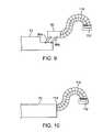
- FIG. 6shows another variation of the end effector assembly in which the off-axis visualization assembly may be utilized with at least one articulatable off-axis tool arm.
- FIG. 7shows another variation of the end effector assembly in which an inflatable balloon may be utilized for providing an atraumatic surface during low-profile advancement of the end effector.
- FIG. 8shows another variation in which a cap may be utilized at the distal end of the assembly to provide an atraumatic surface for low-profile advancement.
- FIG. 9shows yet another variation of the off-axis visualization lumen in which an articulatable lumen disposed upon a reconfigurable platform may be configured such that visualization of the tissue region of interest directly beneath the imager may be provided.
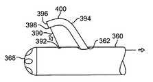
- FIG. 10shows yet another variation of the off-axis visualization lumen attached to the distal end of the elongate body.
- FIG. 11illustrates an exploded assembly view of one variation for the tool arms.
- FIG. 12illustrates a side view of the tool arms in a deployed configuration.
- FIGS. 13A to 13Dillustrate possible movements of the articulatable off-axis tool arms relative to the elongate body.
- FIG. 14illustrates the possible longitudinal advancement of at least one tool arm relative to the elongate body.
- FIG. 15illustrates the possible rotational motion of at least one tool arm about its longitudinal axis relative to the elongate body.
- FIG. 16illustrates some of the possible articulation of the tool arms relative to one another.
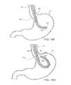
- FIGS. 17A and 17Billustrate one example for advancing an elongate body transesophageally into the stomach for performing a procedure.
- FIGS. 18A to 18Cillustrate another variation of the elongate body having two adjacent sections which are articulatable relative to each other and which are also optionally rigidizable to retain a desired configuration.
- FIGS. 18D and 18Eillustrate yet another variation of the elongate body having three adjacent sections which are all articulatable relative to each other and which are also optionally rigidizable to retain a desired configuration.
- FIGS. 18F to 18Hillustrate an example of a three-sectioned variation of the elongate body being advanced transesophageally into the stomach and articulated to position its distal end near or adjacent to the gastroesophageal junction.
- FIG. 18Iillustrates another example of FIGS. 18F to 18H in which at least one the bendable sections may be articulated in an opposing direction relative to the remaining two bendable sections to further articulate the elongate body within the stomach.
- FIG. 19shows an end view of one variation of the cross-section of the elongate body providing two lumens for their respective tool arms and a single lumen for the visualization apparatus or endoscope.
- FIGS. 20A and 20Bshow end and side views of an example of an individual link through which the working lumens may be positioned.
- FIGS. 21A and 21Bshow other variations of the cross-section of the elongate body providing two lumens for their respective tool arms, a lumen for visualization, and an auxiliary lumen for an additional instrument to be passed therethrough.
- FIG. 21Cshows a perspective view of an example for lumen positioning relative to one another for the configuration of FIG. 21A .
- FIGS. 22A and 22Bshow perspective detail views of an example of the handle assembly optionally having a rigidizable elongate body; in a first configuration in FIG. 22A , rigidizing control is actuated or depressed to rigidize or shapelock the elongate body and in a second configuration in FIG. 22B where rigidizing control may be released to place the elongate body in a flexible state.
- FIG. 22Cshows an end view of the handle of FIG. 22B revealing the open lumen for the passage of tools, instruments, and/or visualization fibers, etc., therethrough.
- FIG. 23shows an exploded perspective view of a sealable or gasketed port assembly which may be attached to the handle for passing tools and/or instruments therethrough while maintaining a seal.
- FIGS. 24A and 24Billustrate perspective and partial cross-sectional side views, respectively, of yet another variation of the endoluminal tissue treatment assembly having an endoscope which may be passed through an opening in the elongate body, which is optionally rigidizable, for providing off-axis visualization.
- FIGS. 25A and 25Billustrate yet another variation where the articulatable sections of the elongate body may be configured to have different lengths.
- FIG. 26shows another variation in which the articulatable tools may be passed through an opening defined along the elongate body which also has an articulatable distal portion to provide for off-axis visualization.
- FIGS. 27A to 27Cshow yet another variation in which the tool arms may be configured to have predetermined configurations once advanced distally of the elongate body.
- FIG. 27Dshows yet another variation in which the articulatable tool arms may be freely rotated relative to the elongate body.
- FIG. 28shows yet another variation in which an imaging chip, e.g., a CCD chip, may be disposed upon the end of a guidewire having a predetermined configuration to provide for visualization of the tissue region; the imaging chip may transmit its images via wire through the guidewire or wirelessly to a receiver located externally of a patient body.
- an imaging chipe.g., a CCD chip
- FIG. 29shows yet another variation in which an imaging chip may be disposed upon a pivoting member.
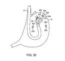
- FIG. 30shows another variation where imaging and/or lighting during a procedure may be provided via imaging capsules and/or LEDs temporarily attached within the patient body and which transmit their images wirelessly to a receiver outside the patient body.
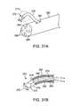
- FIG. 31Ashows an imaging assembly or endoscope passed through an opening or skive defined along the outer surface of an elongate body.
- FIG. 31Bshows a cross-sectional illustration of the articulatable imaging assembly having a rotatable housing contain an imager.
- FIGS. 32A to 32Cshow an instrument utilizing a pull-wire to control the off-axis articulation of the imaging assembly.
- FIGS. 33A and 33Bshow an elongate body having a swing arm rotatably connected via a pivot to direct the positioning of the imaging assembly in an off-axis configuration.
- FIGS. 34A and 34Bshow a balloon assembly which may be configured to conform into a bent or curved configuration for positioning of the imaging assembly in an off-axis configuration.
- FIGS. 35A and 35Bshow a sleeve having a pre-formed bend or curve shape which may be wrapped or at least partially surrounded around an endoscope to position the imaging assembly in an off-axis configuration.
- FIGS. 36A and 36Bshow a sleeve made from an electro-active polymer which may be actuated to reconfigure a position of the imaging assembly.
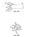
- FIGS. 37A and 37Bshow side and end views, respectively, of a variation utilizing two or more off-axis visualization elements which are reconfigurable between a straightened and curved configuration.
- FIGS. 38A and 38Bshow another variation where two or more off-axis visualization elements may be constrained within a retractable retaining sleeve.
- FIGS. 39A and 39Billustrate an inflatable balloon assembly in an un-inflated and inflated state where the balloon defines one or more curved lumens therethrough for passing tools or instruments through.
- FIG. 39Cshows a perspective view of the assembly of FIG. 39B with the balloon in its inflated configuration.
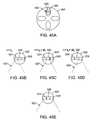
- FIGS. 40A and 40Bshow an endoscope or imaging assembly which may be articulated from a first off-axis position to a second off-axis position to result in an expanded field-of-view.
- FIGS. 41A and 41Bshow another variation for articulating an endoscope or imaging assembly from a first off-axis position to a proximal second off-axis position through an opening or skive along the elongate body.
- FIG. 42shows an example of an elongate body which utilizes multiple skives along its length.
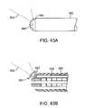
- FIGS. 43A and 43Bshow side and partial cross-sectional side views, respectively, of an in-line imaging assembly for providing off-axis visualization utilizing a rotatable element.
- FIGS. 44A and 44Bshow partial cross-sectional side and end views, respectively, of another variation of an in-line imaging assembly utilizing one or more pivoting reflectors.
- FIG. 45Ashows an example of a visualization enhancement where an imaging assembly may provide multiple adjacent imaging chips, e.g., CCD or CMOS.
- FIGS. 45B to 45Eillustrate how sequential imaging, capturing, and processing of the captured images can be utilized to provide for panoramic endoluminal visualization.
- FIG. 46illustrates another example for image enhancement utilizing a combined fluoroscopic-endoscopic imaging system for display on a monitor and/or goggles.
- Endoluminal accessmay be achieved more effectively by utilizing off-axis articulation with an endoluminal tissue manipulation assembly advanced within a body lumen, e.g., advanced endoluminally or laparoscopically within the body lumen.
- off-axis articulating elementsmay act as reconfigurable platforms from which various tools and/or imagers may be advanced or therapies may be conducted.
- the endoluminal tissue manipulation 10 assembly as described hereinmay comprise, at least in part, a distal end effector assembly 12 disposed or positionable at a distal end of a flexible and elongate body 14 .
- a handle assembly 16may be connected to a proximal end of the elongate body 14 and include a number of features or controls for articulating and/or manipulating both the elongate body 14 and/or the distal end effector assembly 12 .
- the elongate body 14may optionally utilize a plurality of locking or lockable links nested in series along the length of the elongate body 14 which enable the elongate body 14 to transition between a flexible state and a rigidized or shape-locked configuration. Details of such a shape-lockable body may be seen in further detail in U.S. Pat. Nos. 6,783,491; 6,790,173; and 6,837,847, each of which is incorporated herein by reference in its entirety. Alternatively, elongate body 14 may comprise a flexible body which is not rigidizable or shape-lockable but is flexible in the same manner as a conventional endoscopic body, if so desired.
- elongate body 14may also incorporate additional features that enable any number of therapeutic procedures to be performed endoluminally.
- Elongate body 14may be accordingly sized to be introduced per-orally.
- elongate body 14may also be configured in any number of sizes, for instance, for advancement within and for procedures in the lower gastrointestinal tract, such as the colon.
- Elongate body 14may comprise several controllable bending sections along its length to enable any number of configurations for the elongate body 14 .
- Each of these bending sectionsmay be configured to be controllable separately by a user or they may all be configured to be controlled simultaneously via a single controller.
- each of the control sectionsmay be disposed along the length of elongate body 14 in series or they may optionally be separated by non-controllable sections.
- one, several, or all the controllable sections(optionally including the remainder of elongate body 14 ) may be rigidizable or shape-lockable by the user.
- elongate bodymay include a first articulatable section 24 located along elongate body 14 .
- This first section 24may be configured via handle assembly 16 to bend in a controlled manner within a first and/or second plane relative to elongate body 14 .
- elongate body 14may further comprise a second articulatable section 26 located distal of first section 24 .
- Second section 26may be configured to bend or articulate in multiple planes relative to elongate body 14 and first section 24 .
- elongate body 14may further comprise a third articulatable section 28 located distal of second section 26 and third section 28 may be configured to articulate in multiple planes as well, e.g., 4-way articulation, relative to first and second sections 24 , 26 .
- one or each of the articulatable sections 24 , 26 , 28 and the rest of elongate body 14may be configured to lock or shape-lock its configuration into a rigid set shape once the articulation has been desirably configured.
- articulatable bending sectionswhich may be selectively rigidized between a flexible configuration and a shape-locked configuration may be seen, e.g., in U.S. Pat. Pub. Nos. 2004/0138525 A1, 2004/0138529 A1, 2004/0249367 A1, and 2005/0065397 A1, each of which is incorporated herein by reference in its entirety.
- three articulatable sectionsare shown and described, this is not intended to be limiting as any number of articulatable sections may be incorporated into elongate body 14 as practicable and as desired.
- Handle assembly 16may be attached to the proximal end of elongate body 14 via a permanent or releasable connection.
- Handle assembly 16may generally include a handle grip 30 configured to be grasped comfortably by the user and an optional rigidizing control 34 if the elongate body 14 and if one or more of the articulatable sections are to be rigidizable or shape-lockable.
- Rigidizing control 34 in this variationis shown as a levered mechanism rotatable about a pivot 36 .
- Depressing control 34 relative to handle 30may compress the internal links within elongate body 14 to thus rigidize or shape-lock a configuration of the body while releasing control 34 relative to handle 30 may in turn release the internal links to allow the elongate body 14 to be in a flexible state.
- Further examples of rigidizing the elongate body 14 and/or articulatable sectionsmay again be seen in further detail in U.S. Pat. Pub. Nos. 2004/0138525 A1, 2004/0138529 A1, 2004/0249367 A1, and 2005/0065397 A1, incorporated above by reference.
- rigidizing control 34is shown as a lever mechanism, this is merely illustrative and is not intended to be limiting as other mechanisms for rigidizing an elongate body, as generally known, may also be utilized and are intended to be within the scope of this disclosure.
- Handle assembly 16may further include a number of articulation controls 32 , as described in further detail below, to control the articulation of one or more articulatable sections 24 , 26 , 28 .
- Handle 16may also include one or more ports 38 for use as insufflation and/or irrigation ports, as so desired.
- end effector assembly 12may be positioned thereupon.
- end effector assembly 12may include first tissue manipulation arm 20 and second tissue manipulation arm 22 , each being independently or simultaneously articulatable and each defining a lumen for the advancement of tools or instruments therethrough.
- Each of the tools or instrumentsmay be advanced through tool ports 40 located in handle assembly 16 to project from articulatable arms 20 , 22 and controlled from handle assembly 16 or proximal to handle assembly 16 .
- various tools or instrumentsmay be attached or connected directly to the distal ends of arms 20 , 22 and articulatable from handle assembly 16 .
- At least one of the articulatable arms 20 , 22may be articulatable to reconfigure from a low-profile straightened configuration to a deployed configuration where at least one of the arms 20 , 22 is off-axis relative to a longitudinal axis of elongate body 14 .
- Various articulation and off-axis configurations for articulatable arms 20 , 22may be seen in further detail in U.S. Pat. Pub. Nos. 2004/0138525 A1, 2004/0138529 A1, 2004/0249367 A1, and 2005/0065397 A1, incorporated above by reference.
- End effector assembly 12may further include a visualization lumen or platform 18 which may be articulatable into a deployed configuration such that a lumen opening or distal end of visualization lumen or platform 18 is off-axis relative to the longitudinal axis of elongate body 14 , as described in further detail below.
- a visualization lumen or platform 18which may be articulatable into a deployed configuration such that a lumen opening or distal end of visualization lumen or platform 18 is off-axis relative to the longitudinal axis of elongate body 14 , as described in further detail below.
- FIGS. 2A and 2Bshow illustrative perspective views of a variation of the end effector assembly 12 in a deployed configuration and a low-profile delivery configuration, respectively.
- first and second articulatable arms 20 , 22may be seen in an off-axis configuration with a first tool 42 , e.g., any conventional tool such as a Maryland dissector, Babcock graspers, etc., advanced through first tool lumen 46 within first articulatable arm 20 .
- second articulatable arm 22may have a second tool 44 , e.g., any conventional tool such as claw graspers, needle knife, etc., advanced through second tool lumen 48 within second articulatable arm 22 .
- First and second tools 42 , 44may be articulated separately or simultaneously for tissue manipulation and advanced freely distally and proximally through their respective tool lumens 46 , 48 .
- Visualization lumen or platform 18may also be seen in FIG. 2A articulated into its off-axis configuration relative to elongate body 14 .
- Visualization lumen opening 50 defined at the distal end of visualization platform 18may be seen articulated into an off-axis configuration which directs visualization opening 50 such that the field-of-view provided therefrom is directly over or upon an area occupied by the articulated tool arms 20 , 22 and respective tools 46 , 48 .
- Visualization from platform 18may be provided by any number of different methods and devices. In a first example, visualization may be provided by an endoscope 56 having imaging capabilities advanced through elongate body 14 and through visualization platform 18 .
- Imaging endoscope 56may be advanced distally to project from lumen opening 50 or it may be positioned within visualization platform 18 such that its distal end is proximal of or flush with lumen opening 50 .
- imaging electronicssuch as CCD imaging chips or any other number of imaging chips may be positioned within visualization platform 18 to provide images of the field-of-view. These electronic images may be transmitted through wires proximally through elongate body 14 or they may alternatively be transmitted wirelessly to a receiver located externally of the patient body, as described below in further detail.
- FIG. 2Bshows the end effector assembly 12 in a low-profile configuration for endoluminal advancement through a patient body.
- An atraumatic distal tip 54may be provided over the distal end of elongate body 14 and separate atraumatic distal tips 52 may also be provided as well over the distal ends of first and second articulatable tool arms 20 , 22 .
- FIG. 3shows a side view of the end effector assembly 12 of the apparatus of FIG. 2A .
- first and second tools 42 , 44may be withdrawn into their respective tool lumens 46 , 48 during endoluminal advancement of elongate body 14 through the patient and advanced through tool lumens 46 , 48 prior to or after articulation of arms 20 , 22 .
- visualization platform 18if a visualization endoscope is advanced therethrough, endoscope 56 may be positioned within platform 18 during endoluminal advancement of elongate body 14 or after platform 18 has been articulated.
- FIGS. 4A and 4Bshow an example of the image which an off-axis visualization platform 18 may provide during a tissue manipulation procedure.
- the visualization image 60as may be seen on a monitor by the physician during a procedure provides for an off-axis view of the tissue region of interest as well as first and second tools 42 , 44 and articulatable arms 20 , 22 .
- Such an “overhead” perspectiveenables the physician to gain an overview of the tissue region of interest during a procedure and facilitates the procedure by further enabling the physician to triangulate the location of the tools 42 , 44 with respect to the tissue. Accordingly, manipulation of first tissue region 64 and second tissue region 66 may be readily accomplished by the physician while viewing the tissue region from off-axis platform 18 .
- the tissue regions 64 , 66may be manipulated by articulatable tool arms 20 , 22 , even when the tissue regions are approximated towards one another; such tissue manipulation and visualization would generally be extremely difficult, if not impossible, using conventional endoscopic devices and tools which are typically limited to straight-line tools and obstructed views typically afforded conventional endoscopes.
- the utilization of off-axis visualization and off-axis tool articulationmay thereby enable the effective triangulation of various instruments to permit complex, two-handed tissue manipulations.
- the end effector assembly 12may accordingly be utilized to facilitate any number of advanced endoluminal procedures, e.g., extended mucosal resection, full-thickness resection of gastric and colonic lesions, and gastric remodeling, among other procedures.
- assembly 10may be utilized in procedures, e.g., trans-luminal interventions to perform organ resection, anastomosis, gastric bypass or other surgical indications within the peritoneal cavity, etc.
- Visualization assembly 70may generally comprise elongate body 72 having longitudinal axis W, distal region 73 and lumen 74 .
- elongate body 72may comprise a rigidizable and/or articulatable body or it may comprise a passively flexible body.
- Assembly 70further may further comprise articulating element or platform 80 disposed near distal region 73 of elongate body 72 .
- Platform 80may be coupled to the elongate body by linkages 96 a , 96 b rotatably disposed between hinges 92 a , 94 a and 92 b , 94 b , respectively.
- Articulating platform 80 via hinges 92 a , 94 a and 92 b , 94 bmay allow for lumens or lumen 74 to be unobstructed with the platform 80 articulated away from the openings.
- Visualization assembly 70may be seen in further detail in U.S. patent application Ser. No. 10/824,936, which has been incorporated herein above by reference.
- Articulating platform 80may further comprise articulatable visualization lumen 82 .
- Visualization lumen 82may be passively articulatable or, alternatively, may be actively controllable. Any number of conventional methods may be utilized to articulate the shape and configuration of lumen 82 .
- lumen 82illustratively may, for example, be steerable in any number of directions.
- lumen 82may be steerable in at least four directions, e.g., via four control wires routed through or along cable 84 and elongate body 72 to a proximal region of assembly 70 for manipulation by a medical practitioner. Cable 84 may also be used to articulate platform 80 .
- the control wires for steerable lumen 82may be routed through or along body 72 in spaces that would not be usable as working lumens or for tool insertion.
- articulating platform 80 and steerable lumen 82are typically aligned with axis W of elongate body 72 .
- the ability to articulate platform 80 off-axis post-deliveryallows assembly 70 to have both a large working lumen 74 and a small collapsed delivery profile.
- steerable platform 82gives the assembly an off-axis platform with added functionality for performing complex procedures.
- the steering capability of lumen 82may be used to steer therapeutic or diagnostic tools, and/or for illumination, visualization, fluid flushing, suction, etc., into better position for conducting such procedures.
- Various methods and apparatus for controlling elements used in conjunction with lumen 82may be routed through cable 84 along with the control wires for lumen 82 .
- electrical wiresmay run through cable 84 for sending and/or receiving signals, power, etc., to/from the visualization element.
- the visualization elementwould allow direct visualization during insertion within a body lumen, while providing off-axis visualization and steering, as well as facilitating tool introduction, post-articulation.
- cable 84may comprise a lumen for connecting the shaft lumen to a lumen extending through elongate body 72 of assembly 70 through which any number of visualization instruments may be advanced through.
- various imaging modalitiessuch as CCD chips and LED lighting may also be positioned within or upon lumen 82 .
- an imaging chipmay be disposed or positioned upon or near the distal end of lumen 82 to provide for wireless transmission of images during advancement of assembly 70 into a patient and during a procedure.
- the wireless imagermay wirelessly transmit images to a receiving unit RX located externally to a patient for visualization.
- Assembly 70comprising multiple articulating elements having steerable shafts.
- Assembly 70 ′may comprise first articulating platform 80 a and second articulating platform 80 b .
- Platform 80may comprise first steerable lumen 82 a and second steerable lumen 82 b , respectively.
- Lumens 74 a and 74 bextend through elongate body 72 ′ and are exposed upon articulation of platform 80 a and 80 b , respectively.
- a single lumen or more than two lumensalternatively may be provided.
- more than two articulating elements and/or steerable shaftsoptionally may be provided.
- First steerable lumen 82 aillustratively is shown with working lumen 86 that extends through the lumen, as well as through cable 84 a and elongate body 72 ′.
- Exemplary grasper tool 90is shown advanced through lumen 86 .
- Second steerable lumen 82 billustratively is shown with visualization element 88 , as previously described, coupled to an end thereof. Electrical wires, e.g., for powering and transmitting signals to/from the visualization element, may be disposed within cable 84 b .
- steerable lumens 82may be provided with additional or alternative capabilities.
- visualization element 88being a wireless imager, electrical wires may be omitted altogether.
- atraumatic tipsfor use with the assembly 70 are described.
- assembly 70is shown with atraumatic tip 76 .
- Tip 76provides a smooth transition between elongate body 72 and articulating platform 80 with steerable lumen 82 .
- Tip 76may, for example, comprise an inflatable balloon 77 that may be inflated as shown during insertion and delivery of assembly 70 , then deflated prior to articulation of platform 80 and off-axis steering of lumen 82 , so as not to block or impede articulation or the distal opening of the lumen 74 post-articulation.
- assembly 100may comprise an alternative atraumatic tip 78 having cap 79 , which optionally may be fabricated from rubber.
- Cap 79may be U-shaped to both provide a smooth transition between elongate body 102 and articulating platform 106 in the delivery configuration, as well as to ensure that the cap does not block or impede lumen 104 post-articulation.
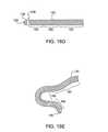
- FIGS. 9 and 10show additional alternative configurations of the articulatable platform and visualization lumen.
- Articulatable visualization lumen 110may be manipulated to articulate in an off-axis configuration such that visualization lumen opening 112 is directed to face in a direction which is off-axis relative to a longitudinal axis of elongate body 72 and which is also perpendicular relative to the longitudinal axis.
- visualization lumen 110may be articulated to face any number of directions, such a configuration may allow for a visualization element positioned within opening 112 to directly face over or upon the tissue region of interest, if so desired.
- visualization lumen 110may be positioned upon platform 80 and articulated via linkages 96 a , 96 b , as described above.
- visualization lumen 110may also be directly attached via interface 114 to elongate body 72 and articulated therefrom, also as described above.
- FIG. 11illustrates one variation for assembly of the elongate body 120 .
- Distal end effector assembly 12has been omitted merely for the sake of clarity from FIG. 11 and following figures.
- the elongate body 120may have a single lumen therethrough for a variety of uses, such as for passage of one or more instruments or for the passage of air or fluid, such as for aspiration or suction.
- the elongate body 120may have more than one lumen passing therethrough, each lumen used for a different function.
- elongate body 120may include at least one instrument or tool lumen 130 , e.g. an arm guide lumen, which extends over or through at least a distal section of the elongate body 120 , typically along the majority of the length of the body 120 as shown.
- instrument or tool lumen 130e.g. an arm guide lumen
- two arm guide lumens 130are shown, each extending from a position along the shaft 120 near the proximal end 122 to the distal tip 126 .
- the elongate body 120includes a visualization lumen 128 , which extends through the shaft 120 to the distal tip 126 .
- the assemblyalso includes at least one tool arm 132 , two are shown in FIG. 11 , each arm 132 of which is insertable through a separate arm guide lumen 130 as indicated by the dashed lines.
- Each tool arm 132has a proximal end 134 , a distal end 136 and a shaft 140 therebetween.
- the distal end 136optionally is steerable, such as by manipulation of adjacent links as schematically indicated. Such steerability may be controlled by any number of methods, e.g., a steering cuff 138 , which is part of the proximal end 134 .
- the shaft 140is typically flexible or deflectable to allow deflection of the surrounding elongate body shaft 120 .
- Each tool arm 132may additionally include a tool deployment lumen 142 therethrough.
- Elongate body 120includes at least one tool 144 with two tools 144 shown in FIG. 11 .
- Each tool 144includes a distal end 146 , a proximal end 148 and an elongate shaft 150 therebetween to allow passage through the tool deployment lumen 142 of the tool arm 132 , or through lumen 130 of elongate body 120 .
- Each tool 144has an end effector 152 disposed at the distal end 146 and optionally a handle 154 at the proximal end 148 for manipulation of the end effector 152 from outside the body. The tool 144 is advanced so that the end effector 152 emerges from the distal end 136 of the arm 132 , or from distal tip 126 of elongate body 120 .
- tool 144optionally may be formed integrally with tool arm 132 . Accordingly, rather than utilizing one or more tool arm shafts 140 insertable through elongate body 120 , articulatable distal ends 136 may alternatively be connected directly near or at the distal tip 126 of elongate body 120 . Additionally, the distal ends of tools 144 may also be connected directly to articulatable distal ends 136 .
- FIG. 12illustrates the assembly of FIG. 11 in an exemplary assembled arrangement.
- the tool arms 132are shown inserted through the arm guide lumens 130 of the elongate body shaft 120 .
- the steerable distal ends 136 of the arms 132protrude from the distal end 124 of the elongate body 120 and the proximal ends 134 of the arms 132 protrude from the proximal end 122 of the elongate body 120 .
- the tools 144are shown inserted through the tool deployment lumens 142 so that the end effectors 152 extend beyond the steerable distal ends 136 of the arms.
- the proximal ends 148 of the tools 144 with handles 154may protrude proximally from the assembly.
- the articulatable visualization lumen 18 or 110may be connected to the distal end of 124 of elongate body 120 at the location of lumen 128 .
- an endoscope used for visualizationmay be routed directly through lumen 128 .
- FIGS. 13A to 13Dillustrate a series of movements of the steerable distal ends 136 of the tool arms 132 .
- This seriesserves only as an example, as a multitude of movements may be achieved by the distal ends 136 independently or together.
- articulatable visualization lumen or platform 18 or 110has been omitted from the illustrations merely for the sake of clarity.
- FIG. 13Aillustrates the distal tip 126 of the elongate body 120 .
- the visualization lumen 128is shown along with two arm guide lumens 130 .
- FIG. 13Billustrates the advancement of the distal ends 136 of the tool arms 132 through the arm guide lumens 130 so that the arms 132 extend beyond the distal tip 126 .
- FIGS. 13C and 13Dillustrate deflection of the arms 132 to an exemplary arrangement.
- FIG. 13Cillustrates deflection of the arms 132 laterally outward. This may be achieved by curvature in the outward direction near the base 156 of the steerable distal end 136 .
- FIG. 13Dillustrates deflection of the tip section 158 of the distal end 136 laterally inward achieved by curvature in the inward direction.
- articulatable visualization lumen 18 or 110when articulatable visualization lumen 18 or 110 is positioned within or connected to lumen 128 , articulation of the visualization lumen into its off-axis configuration will bring tools 132 , and in particular the distal ends 136 of tool arms 132 into the field-of-view, as described above.
- deflection of the arms 132may be achieved with the use of adjacent links 160 in the areas of desired curvature.
- FIGS. 14 to 16illustrate additional possible movements of the tool arms 132 .
- FIG. 14illustrates possible axial movement of the tool arms 132 .
- Each tool arm 132can independently move distally or proximally, such as by sliding within the tool deployment lumen 142 , as indicated by the arrows. Such movement may maintain the arms 132 within the same plane, yet allows more diversity of movement and therefore surgical manipulations.
- FIG. 15illustrates rotational movement of the tool arms 132 .
- Each tool arm 132can independently rotate, such as by rotation of the arm 132 within the tool deployment lumen 142 , as indicated by circular arrow. Such rotation may move the arm or arms 132 through a variety of planes.
- the arms 132and therefore the tools 144 positioned therethrough (or formed integrally therewith), may be manipulated through a wide variety of positions in one or more planes.
- FIG. 16illustrates further articulation of the tool arms 132 .
- the arms 132may be deflectable to form a predetermined arrangement. Typically, when forming a predetermined arrangement, the arms 132 are steerable up until the formation of the predetermined arrangement wherein the arms 132 are then restricted from further deflection. In other variations, the arms 132 may be deflectable to a variety of positions and are not limited by a predetermined arrangement. Such an example is illustrated in FIG. 16 wherein the arms 132 articulate so that the tip sections 158 curl inwardly.
- the tip sections 158may be positioned in front of the lumen 128 and imager 162 for viewing or within the field-of-view provided by the off-axis articulation of visualization lumen 18 or 110 (omitted for clarity). Typically, the tip sections 158 may be positioned on opposite sides of a longitudinal axis 166 of the elongate body 120 , wherein for an imager 166 positioned within lumen 128 , in one variation, the field-of-view (indicated by arrow 164 ) may span up to, e.g., approximately 140 degrees.
- FIGS. 17A and 17Billustrate one example for use of the endoluminal assembly 10 .
- FIG. 17Aillustrates advancement of the elongate body 120 through the esophagus E to the stomach S, as shown in FIG. 17A .
- the elongate body 120may then be steered to a desired position within the stomach S, and a tissue region of interest M may be visualized by visualization lumen or platform 18 , which may be articulated into its off-axis configuration, as shown in FIG. 17B .
- Tool arms 132may also be advanced, if not already attached directly to the distal end of elongate body 120 , through the elongate body 120 and articulated.
- one or several tools 144may be advanced through the tool arms 132 , or an end effector 152 may be disposed at the distal end of each arm 132 .
- a grasper 168is disposed at the distal end of one arm 132 and a cutter 81 is disposed at the distal end of the other arm 132 , although any number of tools, e.g., graspers, biopsy graspers, needle knives, snares, etc., may be utilized depending upon the desired procedure to be performed.
- the tools 144may alternatively be affixed upon the distal ends of tool arms 132 and atraumatic tips may be provided thereupon to prevent trauma to contacted tissue during endoluminal advancement.
- the systems, methods and devices of the present inventionare applicable to diagnostic and surgical procedures in any location within a body, particularly any natural or artificially created body cavity.
- Such locationsmay be disposed within the gastrointestinal tract, urology tract, peritoneal cavity, cardiovascular system, respiratory system, trachea, sinus cavity, female reproductive system and spinal canal, to name a few. Access to these locations may be achieved through any body lumen or through solid tissue.
- the stomachmay be accessed through an esophageal or a port access approach, the heart through a port access approach, the rectum through a rectal approach, the uterus through a vaginal approach, the spinal column through a port access approach and the abdomen through a port access approach.
- a variety of proceduresmay be performed with the systems and devices of the present invention.
- the following proceduresare intended to provide suggestions for use and are by no means considered to limit such usage: laryngoscopy, rhinoscopy, pharyngoscopy, bronchoscopy, sigmoidoscopy, colonoscopy, esophagogastroduodenoscopy (EGD) which enables the physician to look inside the esophagus, stomach, and duodenum.
- endoscopic retrograde cholangiopancreatographymay be achieved which enables the surgeon to diagnose disease in the liver, gallbladder, bile ducts, and pancreas.
- endoscopic sphincterotomycan be done for facilitating ductal stone removal.
- ERCPmay be important for identification of abnormalities in the pancreatic and biliary ductal system.
- Other treatmentsinclude cholecystectomy (removal of diseased gallbladder), CBD exploration (for common bile duct stones), appendicectomy.
- endoscopies(diagnostic as well as therapeutic endoscopies), pyloroplastic procedures (for children's congenital deformities), colostomy, colectomy, adrenalectomy (removal of adrenal gland for pheochromocytoma), liver biopsy, gastrojejunostomy, subtotal liver resection, gastrectomy, small intestine partial resections (for infarction or stenosis or obstruction), adhesions removal, treatment of rectum prolaps, Heller's Myotomy, devascularization in portal hypertension, attaching a device to a tissue wall and local drug delivery to name a few.
- elongate body 120has a proximal end 122 and a distal end 124 terminating in a distal tip 126 .
- Elongate body 120may include one or more sections or portions of elongate body 120 in which each section may be configured to bend or articulate in a controlled manner.
- a first section along elongate body 120may be adapted to be deflectable and/or steerable, shape-lockable, etc.
- a second sectionwhich may be located distally of and optionally adjacent to the first section along elongate body 120 , may be adapted to retroflex independent of in conjunction with the first section. In one variation, this second section may be laterally stabilized and deflectable in a single plane.
- An optional third sectionwhich may be located distally of and optionally adjacent to the second section, may be adapted to be a steerable portion, e.g., steerable within any axial plane in a 360-degree circumference around the shaft.
- a third sectionis utilized as the most distal section along elongate body 120 , such steerability may allow for movement of the distal tip of elongate body 120 in a variety of directions.
- Such sectionswill be further described below.
- the elongate body 120may be comprised of any combination of sections and may include such sections in any arrangement.
- the elongate body 120may be comprised of any subset of the three sections, e.g., first section and third section, or simply a third section.
- additional sectionsmay be present other than the three sections described above.
- multiple sections of a given varietye.g. multiple sections adapted to be articulated as second section above, may be provided.
- one or all three sectionsmay be independently lockable, as will be described below.
- FIG. 18AOne variation of the elongate body 120 is illustrated in FIG. 18A in a straightened configuration. Only elongate body 120 is shown in these illustrations and the end effector assembly with off-axis tool arms and off-axis visualization has been omitted merely for the sake of clarity. Because the elongate body 120 is used to access an internal target location within a patient's body, elongate body 120 may include a deflectable and/or steerable shaft 120 . Thus, FIG. 18B illustrates the elongate body 120 having various curvatures in its deflected or steered state. The elongate body 120 may be steerable so that the elongate body 120 may be advanced through unsupported anatomy and directed to desired locations within hollow body cavities.
- the elongate body 120includes a first section 180 which is proximal to a second section 182 , as indicated in FIG. 18B .
- first section 180may be adapted to lock its configuration while the second section 182 is further articulatable, as illustrated in FIG. 18C where first section 180 is shown in a locked position and the second section 182 is shown in various retroflexed positions.
- second section 182When retroflexed, second section 182 may be curved or curled laterally outwardly so that the distal tip 126 is directable toward the proximal end 122 of the elongate body 120 . Moreover, the second section 182 may be configured to form an arc which traverses approximately 270 degrees, if so desired. Optionally, the second section 182 also may be locked, either when retroflexed or in any other position. As should be understood, first section 180 optionally may not be steerable or lockable. For example, section 180 may comprise a passive tube extrusion.
- elongate body 120may include a first section 180 proximal to a second section 182 , which is proximal to a third section 184 .
- First section 180may be flexible or semi-flexible, e.g. such that the section 180 is primarily moveable through supported anatomy, or is moveable through unsupported anatomy via one or more stiffening members disposed within or about the section.
- the first section 180may be comprised of links or nestable elements which may enable the first section 180 to alternate between a flexible state and a rigidized stated.
- first section 180may comprise locking features for locking the section in place while the second section 182 is further articulated.
- the second section 182may be configured to be adapted for retroflexion. In retroflexion, as illustrated in FIG. 18E , second section 182 may be curved or curled laterally and outwardly so that a portion of second section 182 is directed toward the proximal end 122 of the elongate body 120 . It may be appreciated that second section 182 may be retroflexed in any desired direction. Optionally, second section 182 may also be locked, either in retroflexion or in any other position.
- first section 180 and second section 182may be locked in place while third section 184 is further articulated. Such articulation is typically achieved by steering, such as with the use of pullwires.
- the distal tip 126preferably may be steered in any direction relative to second section 182 .
- third section 184may move within an axial plane, such as in a wagging motion.
- the third section 184may move through any axial plane in a 360 degree circumference around the axis; thus, third section 184 may be articulated to wag in any direction.
- third section 184may be further steerable to direct the distal tip 126 within any plane perpendicular to any of the axial planes.
- the distal tip 126may be moved in a radial manner, such as to form a circle around the axis.
- FIG. 18Eillustrates third section 184 steered into an articulated position within an axial plane.
- FIGS. 18F and 18HThe variation of elongate body 120 illustrated in FIGS. 18D and 18E having three sections 180 , 182 , 184 with varying movement capabilities are shown in FIGS. 18F and 18H in an example of positioning elongate body 120 within a stomach S through an esophagus E. Since elongate body 120 may be deflectable and at least some of the sections 180 , 182 , 184 may be steerable, elongate body 120 may be advanced through the tortuous or unpredictably supported anatomy of the esophagus and into the stomach S while reducing a risk of distending or injuring the organs, as shown in FIG. 18F .
- second section 182may be retroflexed as illustrated in FIG. 18G .
- distal tip 126may traverse an arc having a continuous radius of curvature, e.g., approximately 270 degrees with a radius of curvature between about 5 to 10 cm.
- distal tip 126may be directed back towards first section 180 near and inferior to gastroesophageal junction GE.
- Second section 182may be actively retroflexed, e.g. via pullwires, or it may be passively retroflexed by deflecting the section off a wall of stomach S while advancing elongate body 120 .
- Second section 182may be configured to be shape-lockable in the retroflexed configuration.
- the distal tip 126may then be further articulated and directed to a specific target location within the stomach. For example, as shown in FIG. 18H , the distal tip 126 may be steered toward a particular portion of the gastroesophageal junction GE.
- Third section 184may optionally be shape-locked in this configuration. Off-axis tools and off-axis visualization may then be deployed through or from elongate body 120 , as described above, to perform any number of procedures.
- FIG. 18Ishows yet another example in which elongate body 120 may be articulated in a manner similar as shown above in FIG. 18H .
- elongate bodymay comprise a first section 180 which is configured to bend or curve in any number of directions.
- first section 180may be configured to articulate in a direction opposite to a direction in which second section 182 bends. This opposed articulation may result in an elongate body 120 which conforms into a question-mark shape to facilitate positioning of third section 184 within stomach S, particularly for procedures which may be performed near or at the gastroesophageal junction GE.
- First section 180may be configured to automatically conform into its opposed configuration upon rigidizing elongate body 120 or it may alternatively be articulated into its configuration by the physician.
- FIGS. 19 , 20 A, and 20 Bshow examples of link variations which may be utilized.
- FIGS. 20A and 20Bshow end and side views, respectively, of one variation of a link which may be utilized for construction of elongate body 120 .
- An exemplary elongate body link 200may be comprised generally of an open lumen 202 through any number of separate lumens, e.g., tool arm lumens, visualization lumens, etc., may be routed through.
- the periphery defining open lumen 202may define a number of openings for passage of various control wires, cables, optical fibers, etc.
- control wire lumens 204may be formed at uniform intervals around the link 200 , e.g., in this example, there are four control wire lumens 204 shown uniformly positioned about the link 200 , although any number of lumens may be utilized as practicable and depending upon the desired articulation of elongate body 120 .
- Elongate body link 200may also comprise a number of auxiliary control lumens 206 spaced around body link 200 and adjacent to control wire lumens 204 . Any number of biocompatible materials may be utilized in the construction of links 200 , e.g., titanium, stainless steel, etc.
- Terminal link 190may be utilized as an interface link between elongate body 120 and the distal end effector assembly 12 .
- terminal link 190may be utilized as an interface link between elongate body 120 and the distal end effector assembly 12 .
- three lumensare utilized in terminal link 190 for a visualization lumen 192 and two tool arm channels 194 , 196 .
- additional lumensmay be defined through the link.
- the off-axis tools arms and off-axis articulatable lumenmay be connected directly to terminal link 190 .
- FIGS. 21A and 21Bshow end views of possible lumen arrangements where four lumens are utilized through elongate body 120 .
- the variation in FIG. 21Ashows elongate body link 200 where visualization lumen 192 and auxiliary instrument lumen 208 may be of a similar size diameter.
- Lumens 192 , 208may be positioned adjacently to one another with tool arm channels 194 , 196 positioned on either side of lumens 192 , 208 .
- auxiliary instrument lumen 208may be adjacently positioned and larger than visualization lumen 192 , in which case tool arm channels 194 , 196 may be positioned on either side of visualization lumen 192 .
- multiple smaller diameter lumensmay be routed through for any number of additional features, e.g., insufflation, suction, fluid delivery, etc.
- FIG. 21Cshows a perspective view of a single elongate body link 200 with visualization lumen 192 , auxiliary instrument lumen 200 , and tool arm channels 194 , 196 routed therethrough.
- Handle assembly 16may generally comprise, in one variation, handle 30 which is connectable to the proximal end of elongate body 120 via elongate body interface 210 . Coupling between the elongate body 120 and interface 210 may be accomplished in a number of different ways, e.g., interference fit, detents, etc., or the proximal link of elongate body 120 and interface 210 may be held adjacently to one another by routing control wires from handle 30 through interface 210 and into elongate body 120 .
- Interface 210may also be adapted to travel proximally or distally relative to handle 30 when rigidizing control 34 is actuated about pivot 36 to actuate a rigidized or shape-locked configuration in elongate body 120 .
- An exampleis shown in FIG. 22A where control 34 is depressed against handle 30 to advance interface 210 distally from handle 30 . This distal movement of interface 210 compresses the links throughout elongate body 120 to rigidize its configuration.
- interface 210may be configured to travel proximally relative to handle 30 such that a connected elongate body 120 is released into a flexible state by decompression of its links.
- Handle 30may also define an elongate body entry lumen 212 which may be defined near or at a proximal end of handle 30 .
- Entry lumen 212may define one or more openings for the passage of any of the tools and instruments, as described herein, through handle 30 and into elongate body 120 .
- One or more ports, e.g., ports 214 , 216which are in fluid communication with one or more lumens routed through elongate body 120 , as described above, may also be positioned on handle 30 and used for various purposes, e.g., insufflation, suction, irrigation, etc.
- handle 30may further include a number of articulation or manipulation controls 32 for controlling elongate body 120 and/or end effector assembly 12 .
- control assembly 32 in this variationmay include a first control 218 for manipulating or articulating first section 180 ; a second control 220 for manipulating or articulating second section 182 in a first plane; and a third control 222 for manipulating or articulating second section 182 in a second plane.
- control assembly 32is configured to have several control wheels which are adjacently positioned relative to one another over a common control axis 224 , as shown in the end view of handle assembly 16 in FIG. 22C .
- Control assembly 32may also include a locking mechanism 226 which may be configured to lock each of the controls 218 , 220 , 222 individually or simultaneously to lock a configuration of each section.
- each of the controls 218 , 220 , 222may be configured to articulate their respective sections along elongate body 120 even when rigidizing control 34 has been articulated to rigidize a shape of the elongate body 120 .
- handle assembly 16may include additional controls for additional sections of elongate body 120 .
- alternative configurations for the control assembly 32may also include articulating levers or sliding mechanisms along handle 30 as control wheels are intended to be merely illustrative of the type of control mechanisms which may be utilized.
- entry lumen 212may define one or more openings for the passage of any of the tools and instruments, as described herein, through handle 30 and into elongate body 120 .
- a port assemblymay be connected or attached to handle 30 proximally of entry lumen 212 in a fluid-tight seal.
- a port assembly alignment post 228 for aligning such a port assemblymay be seen in the end view of FIG. 22C .
- An example of such a port assembly 230is shown in the perspective view of FIG. 23 .
- Port assembly 230may be seen having a visualization port lumen 232 for the insertion and passage of a visualization tool, as well as tool ports 234 , 236 on either side of visualization port lumen 232 for the insertion of tools, as described above.
- Auxiliary instrument port 238may also be seen on port assembly 230 .
- a removable gasket 240made from a compliant material, e.g., polyurethane, rubber, silicon, etc., may be positioned between ports 232 , 234 , 236 , 238 of port assembly 230 and a retainer for securely retaining the gasket against assembly 230 .
- the retainermay also have ports 232 ′, 234 ′, 236 ′, 238 ′ defined therethrough for alignment with their respective ports in assembly 230 for passage of the tools or instruments.
- FIGS. 24A and 24Bshow perspective and partial cross-sectional views, respectively, of a variation of end effector assembly 250 .
- elongate body 252may be a shape-lockable or rigidizable body which may be steerable or non-steerable, as described above, or it may generally be a passively flexible body which may be steerable or non-steerable as well.
- an opening 254may be defined through an outer surface near or at a distal end of elongate body 252 .
- a visualization assembly 256which may generally comprise an endoscope 258 having a bendable or flexible section 260 near or at its distal end, may be advanced through an endoscope or auxiliary instrument lumen 272 defined through elongate body 252 and advanced through opening 254 .
- Endoscope 258may be advanced through opening 254 such that its flexible section 260 enables the end of endoscope 258 to be positioned in an off-axis configuration distal of elongate body 252 .
- endoscope 258may be advanced entirely through lumen 272 such that it is disposed at the distal end of lumen 272 or projects distally therefrom to provide visualization of the tissue region of interest.
- First and second articulatable tool arms 262 , 264 having one or more tools 266 upon their respective distal ends, as described above,may also be advanced through respective first and second tool lumens 268 , 270 .
- Tool arms 262 , 264may be disposed distally of elongate body 252 such that they are within the visualization field provided by the off-axis endoscope 258 .
- elongate body 274may comprise bendable or articulatable sections of varying lengths.
- Elongate body 274 in this variationmay be shape-lockable or rigidizable along its length, as above, or it may have a passively flexible length.
- elongate body 252may have a first section 276 having a length D 1 and a second section 278 having a length D 2 located distally of first section 276 .
- the length D 1 of first section 276may be shorter than the length D 2 of second section 278 , although the length of D 1 may be longer than D 2 in another alternative.
- the lengths D 1 and D 2may be equal.
- having a length of D 1 shorter than length D 2may allow for the end effector assembly to be articulated into a variety of configurations, especially if first section 276 is articulated in a direction opposite to a direction in which second section 278 is articulated, as shown in FIG. 25B .
- Any of the end effector assemblies described hereinmay be utilized with elongate body 252 having various lengths of sections 276 , 278 .
- FIG. 26shows a side profile of end effector assembly 280 in yet another variation.
- end effector assembly 280may have an optionally shape-lockable elongate body 282 with articulatable first section 284 and second section 286 .
- Second section 286may be articulatable into an off-axis configuration such that an imager 288 positioned at its distal end may become positioned to view a region of interest accessible by first and second tool arms 292 , 294 , which may be passed through elongate body 282 and through opening 290 defined in first section 284 into the field-of-view provided by off-axis imager 288 .
- Tool arms 292 , 294may be articulatable tool arms, as described above, or they may comprise any manner of conventional in-line tools.
- FIGS. 27A and 27Bshow perspective views of end effector assembly 300 which may optionally comprise a shape-lockable elongate body 302 with off-axis visualization assembly 256 , as above.
- first and second tool arms 304 , 306may comprise arm members each having a first and second preset bending portion 308 , 310 , respectively, each configured to bend at a preset angle once free from the constraints of the tool lumens, as shown in FIG. 27B .
- tools arms 304 , 306may be rotated about its longitudinal axis, as shown in FIG. 27C , to accomplish any number of procedures on the tissue while visualized via off-axis endoscope 258 .
- Tool arms 304 , 306may be fabricated from shape memory alloys, such as a Nickel-Titanium alloy, or from spring stainless steels, or any other suitable material which may allow for the tools arms 304 , 306 to reconfigure itself from a first low-profile configuration to an off-axis deployment configuration.
- shape memory alloyssuch as a Nickel-Titanium alloy, or from spring stainless steels, or any other suitable material which may allow for the tools arms 304 , 306 to reconfigure itself from a first low-profile configuration to an off-axis deployment configuration.
- FIG. 27Dshows a perspective view of yet another variation in which elongate body 302 may have first and second articulatable tool arms 312 , 314 which are freely rotatable about their respective longitudinal axes.
- Visualization assembly 256may comprise any of the variations described above, particularly the variation as described for FIGS. 24A and 24B .
- FIG. 28shows a perspective view of another variation of end effector assembly 320 in which optionally shape-lockable elongate body 322 may comprise a separate visualization lumen 324 having a lumen opening 326 through which a guidewire 328 having a preset configuration may be advanced.
- Visualization lumen 324may be integrated with elongate body 322 or separately attached to an outer surface of elongate body 322 .
- Guidewire 328may be comprised of a shape memory alloy, as above, and carry an imaging chip 330 , e.g., a CCD imager, on a distal end of the guidewire 328 .
- Guidewire 328may be preset to reconfigure itself into an off-axis configuration to provide the off-axis visualization distally of elongate body 322 , as shown.
- imaging chip 330may be connected via wires through guidewire 328 to a monitor at a location proximal to elongate body 322 or imaging chip 330 may be adapted to wirelessly transmit images to a receiving unit external to a patient body.
- guidewire 328may also be advanced through a working lumen of elongate body 322 if so desired.
- end effector assembly 340 shown in FIG. 29may comprise an optionally shape-lockable body 342 having visualization member 344 pivotably mounted near or at a distal end of body 342 via pivot 348 .
- Visualization member 344may have an imager 346 , e.g., an imaging chip such as a CCD chip, positioned upon a distal end of member 344 , which may be configured to articulate about pivot 348 such that imager 346 is provided an off-axis view of the region distal of elongate body 342 .
- the off-axis visualizationmay be provided, e.g., within the stomach S, via one or more capsules 350 having integrated imagers 352 positioned within one or more regions of the stomach S.
- a number of imaging capsules 350may be temporarily adhered to the interior stomach wall, e.g., via clips 354 attached to the capsule body.
- the imaging portions 352 of the capsules 350may be positioned against the stomach wall such that one or more capsules 350 are pointed towards a tissue region of interest.
- the endoluminal assembly 10may then be articulated towards the tissue region of interest with either off-axis visualization platform 18 or one or more capsules 350 providing a number of off-axis views for any number of procedures to be accomplished.
- Imaging capsulessuch as the PillCamTM are generally used for capsule endoscopy and may be commercially obtained from companies like Given Imaging Ltd. (Israel).
- imaging assembly or endoscope 370may be advanced through visualization lumen 364 , which runs through optionally rigidizable elongate body 360 , and passed through opening or skive 362 defined along the outer surface near the distal end of elongate body 360 .
- Imaging assembly 370may be alternatively passed distally through visualization lumen 364 to the opening defined through the atraumatic distal end 368 .
- imaging assembly 370may be articulated into an off-axis configuration relative to the longitudinal axis of elongate body 360 such that the imaging element at its distal end is directed to the area distal to the elongate body 360 along its longitudinal axis, as described above.
- Such a general configurationmay allow for the viewing of various instruments passed through any of the instrument lumens 366 defined through elongate body 360 .
- imaging assembly 370may have an articulatable imaging element 372 positioned at its distal end, which may be rotated in any number of directions.
- FIG. 31Bshows a cross-sectional illustration of the articulatable imaging element 372 partially removed from imaging assembly 370 .
- Imaging element 372may generally have a rotatable housing 374 containing the imager 376 , e.g., CCD or CMOS chip, connected via at least one electrical wire 380 routed through an imaging assembly lumen 384 defined through assembly 370 to a proximal end of the device.
- the electrical wire 380may be connected to a processor to allow viewing of images from outside the patient body.
- the rotatable housing 374may be rotated in any number of directions, as indicated by the arrows, by alternately tensioning any number of control wires 378 which may be routed through control wire lumens 382 defined through imaging assembly 370 .
- the distal end of imaging assembly 370may be configured to rotatingly receive and hold rotatable housing 374 in a secure manner while the housing 374 is articulated.
- imaging assembly 370may be articulated to direct its distal end to a desired tissue region for optimal imaging
- the addition of an optional rotatable imaging element 372may further facilitate the imaging of various tissue regions without having to reposition the entire assembly.
- FIGS. 32A to 32Cshow an instrument where the optionally rigidizable elongate body 360 may use a pull-wire 390 to control the off-axis articulation of the imaging assembly.
- pull-wire 390may be routed through skive 362 and through a pull-wire opening 392 located distal of skive 362 .
- Pull-wire 390may be routed through pull-wire opening 392 proximally through the length of elongate body 360 where the pull-wire 390 may be controlled.
- the distal end of pull-wire 390may be attached to a distal end of the imaging assembly 394 at attachment point 398 and as imaging assembly or endoscope 394 is advanced through skive 362 , as shown in FIG. 32B , the pull-wire 390 may be tensioned from its proximal end outside the patient body. As shown in FIG. 32C , urging or pulling pull-wire 390 may redirect or bend a distal portion 400 of the imaging assembly 394 with the imager 396 such that the imager 396 is pointed to the region distal to the elongate body 360 .
- FIG. 33Ashows elongate body 360 having a swing arm or member 410 rotatably connected via pivot 412 to the elongate body 360 at a location distal to skive 362 .
- a distal end of swing arm 410may be attached to endoscope 394 via an attachment mechanism 414 , e.g., collar, pinned connection, adhesive, etc., such that when endoscope 394 is urged distally through elongate body 360 and out of skive 362 , the distal end of endoscope 394 is constrained to follow an arc by the swing arm 410 as the distal end of endoscope 394 pivots about pivot 412 , as shown in FIG. 33B .
- the length of swing arm 410may be varied depending upon the desired height and positioning of imager 396 in its off-axis configuration.
- swing arm 410may be configured as a simple length or it may be configured into any number of structures provided that it is able to pivot relative to elongate body 360 and position imager 396 into its off-axis position. Additionally, a mechanical stop may be positioned adjacent to pivot 412 to prevent over-arcing of swing arm 410 ; alternatively, the imaging assembly or endoscope 394 may be limited from being advanced distally out of skive 362 beyond a pre-determined point to prevent over-arcing of the imager 396 .
- a balloon 420which is flexible in its deflated state may be positioned in close contact against a distal portion of the imaging assembly or endoscope 394 .
- Balloon 420may be in fluid communication through inflation lumen 422 through a length of elongate body 360 to an inflation pump 424 located outside the patient body, as shown in FIG. 34A .
- the balloon 420may be configured such that when inflated with a fluid or gas, the inflated balloon 420 conforms to a bent configuration which may be predetermined.
- the balloon 420may, for instance, be inflated only along a single side such that filling the balloon 420 results in an asymmetric shape.
- the balloon 420When the endoscope 394 with balloon 420 is advanced out of skive 362 , the balloon 420 may be inflated via a fluid (such as saline, water, etc.) or gas (such as air, nitrogen, carbon dioxide, etc.) such that the balloon 420 conforms to its bent configuration and also urges the wrapped endoscope 394 to conform into a bent or curved off-axis configuration, as shown in FIG. 34B .
- a fluidsuch as saline, water, etc.
- gassuch as air, nitrogen, carbon dioxide, etc.
- a scaffold or tubular covering having a scaffold 420 ′ embedded therein which is made from a super-elastic or shape-memory materialmay be conformed or wrapped around the distal portion of endoscope 394 .
- a scaffoldmay be made from a super-elastic or shape-memory alloy such as Nitinol. If a super-elastic scaffold is used, the endoscope 394 may be automatically urged into a bent or curved configuration when advanced out of skive 362 .
- a shape-memory alloy scaffoldmay be electrically connected via one or more wires 422 ′ to a power supply 424 ′, which may be activated to actuate the scaffold 420 ′ into a bent or curved configuration.
- FIG. 35AYet another variation is shown in FIG. 35A in which endoscope 394 may be wrapped or at least partially surrounded by a sleeve 430 having a pre-formed bent or curved configuration.
- Sleeve 430may be composed of a super-elastic or shape-memory material scaffold or covering, as described above, which is biased to form the bent or curved configuration when unconstrained.
- a straightening wire or mandrel 432made for example from stainless steel, Nitinol, a polymeric material, etc., may be disposed within sleeve 430 .
- wire or mandrel 432may be pulled or tensioned from its proximal end until it is withdrawn from sleeve 430 , thereby allowing sleeve 430 to reconfigure itself into its relaxed configuration and to redirect imager 396 into its off-axis configuration, as shown in FIG. 35B .
- endoscope 394may be simply pulled proximally through skive 362 while straightening sleeve 430 and back into elongate body 360 .
- EAPelectro-active polymer
- FIG. 36AAnother variation may utilize a sleeve 440 made from an electro-active polymer (EAP) material such as polymer-metal composites, conductive polymers, ferro-electric polymers, etc., as shown in FIG. 36A .
- EAP sleeve 440may be wrapped completely or at least partially about endoscope 394 such that sleeve 440 remains flexibly compliant when passed through elongate body 360 and skive 362 .
- EAP sleeve 440may be electrically connected via electrical connection 442 to a power supply 444 located external to the patient body such that when power supply 444 is activated, EAP sleeve 440 may be stimulated to reconfigure itself into a bent or curved off-axis configuration, as seen in FIG. 36B , such that imager 396 is directed distal to the elongate body 360 .
- Shutting power supply 444 offmay allow EAP sleeve 440 to lose its curved configuration and transition back into its flexible state for withdrawal through skive 362 and from the patient body.
- off-axis visualizationmay utilize multiple, e.g., two or more, off-axis visualization elements. Illustrated in the side view of FIG. 37A , two or more imaging assemblies 450 which are reconfigurable between a straightened and curved configuration may be each advanced through a corresponding lumen 366 defined through elongate body 360 .
- Each imaging assembly 450may be configured such that an imaging element 454 , such as an optical fiber, CCD or CMOS chip, etc., may be mounted near or at the distal end of a curved or bendable section 452 such that when the curved section 452 is advanced from elongate body 360 , the imaging element 454 is directed into an off-axis position relative to the longitudinal axis defined by the elongate body 360 .
- an imaging element 454such as an optical fiber, CCD or CMOS chip, etc.
- two imaging assemblies 450may be advanced through their respective adjacent lumens 366 and rotated within their lumens 366 to align the respective imagers 454 to a common tissue region.
- four imaging assemblies 450may be advanced through respective lumens 366 , as shown in the end view of FIG. 37B , and advanced out of elongate body 360 such that each imaging assembly 450 is radially configured in an off-axis position with respect to the longitudinal axis of elongate body 360 .
- each imaging assembly 450may be uniformly or arbitrarily positioned with respect to one another in its deployed configuration.
- one or more imaging assemblies 450may be advanced through one or more lumens 366 while contained within a tubular retaining sleeve 456 which is retractable with respect to the imaging assembly 450 , as shown in FIG. 38A .
- Retaining sleeve 456may be advanced through lumen 366 from atraumatic distal end 368 prior to or simultaneously with imaging assemblies 450 and retaining sleeve 456 may be retracted relative to imaging assemblies 450 leaving the one or more assemblies 450 to reconfigure into its curved configuration, as shown in FIG. 38B .
- an inflatable balloon assembly 460which defines one or more curved lumens therethrough may be utilized.
- an un-inflated balloon assembly 460may lie in its collapsed shape in a low profile against elongate body 360 .
- a gassuch as nitrogen, carbon dioxide, air, etc.
- liquidsuch as saline, water, etc.
- balloon 462which may be made from a distensible or expandable material may expand, as shown in FIG. 39B .
- balloon 462may define or more unobstructed lumens 466 extending through the balloon 462 from a working lumen opening 470 in elongate body 360 and terminating in a corresponding lumen opening 464 defined along a side or at the terminal end of the balloon 462 , as shown in FIG. 39C .
- Lumens 466may curve radially outward within balloon 462 with respect to the longitudinal axis of elongate body 360 and then curve radially back inwards 468 with respect to the longitudinal axis. This curvature may be such that any tools or endoscopic instruments passed through lumen 466 are directed towards the longitudinal axis of elongate body 360 and to a tissue region of interest for any number of procedures to be performed.
- FIGS. 40A and 40BOne example for endoscopically simulating the repositioning and re-visualizing of a tissue region may be seen in FIGS. 40A and 40B . As illustrated in FIG.
- endoscope or imaging assembly 480may be advanced through elongate body 360 and out of lumen 364 , where imager 484 may be articulated into a first off-axis position relative to a longitudinal axis of elongate body 360 , as described previously. In its first off-axis configuration, a target area distal to elongate body 360 may be visualized within a first field-of-view 486 .
- an articulatable section 482 of endoscope 480may be further urged or articulated from its proximal end outside the patient body into a second off-axis configuration, as shown in FIG. 40B , which is more proximal than the first off-axis configuration.
- the resulting expanded field-of-view 486 ′may thus provide for a larger visual perspective of the target area being visualized without having to reposition a length or the entire length of elongate body 360 relative to the visualized target area.
- endoscope or imaging assembly 480may be positioned into its first off-axis configuration, as above, to provide a first field-of-view 486 , as shown in FIG. 41A .
- Endoscope 480may then be withdrawn at least partially through elongate body 360 and then re-advanced through a skive 362 into a second off-axis configuration such that imager 484 is repositioned proximal of the first off-axis configuration to provide an expanded field-of-view 486 ′, as shown in FIG. 41B .
- Skive 362as described herein and also in U.S. patent application Ser. No. 10/797,485 filed Mar. 9, 2004 (U.S. Pat. Pub. No. 2004/0249367A1), which is incorporated herein by reference in its entirety, may be defined at any number of locations along the length of elongate body 360 proximal to the distal tip 368 .
- Another variationmay incorporate an imaging system having a variable field-of-view which may be altered by repositioning the optics within the imager 484 .
- an alterable field-of-viewis shown and described in U.S. Pat. Pub. No. 2005/0267335 A1 filed May 18, 2005 to Okada et al., which is incorporated herein by reference in its entirety.
- Such a devicemay be optionally incorporated into any of the imaging assemblies described herein as practicable.
- FIG. 42illustrates an example in which multiple skives may be defined along the body.
- endoscope 394may be positioned into its off-axis configuration through a distally positioned skive 362 to provide a first field-of-view.
- An additional second skive 492 and a third skive 494may be positioned proximally along the length 490 such that the endoscope 394 may be positioned in alternate proximal off-axis positions 394 ′, 394 ′′ to provide alternate views of the target area being visualized.
- skivesmay be utilized along the elongate body 490 , as practicable, and the skives may be varied relative to its circumferential position, as desired. For instance, one or more skives may be aligned linearly along the length of elongate body 490 such that the skives are located along the same side of elongate body 490 .
- the one or more skivesmay be aligned in alternating or non-uniform patterns. Furthermore, if the one or more skives are located along different sides of the elongate body 490 , multiple visualization instruments (or multiple other endoscopic instruments) may be passed simultaneously through elongate body 490 to exit each skive, if so desired.
- off-axis imaging relative to the elongate bodymay be provided alternatively by utilizing various in-line angled configurations.
- FIG. 43Aillustrates elongate body 360 with a visualization element positioned near or at the distal end of elongate body 360 to provide an angled field-of-view 500 relative to the longitudinal axis of elongate body 360 .
- FIG. 43Bshows a partial cross-sectional view of elongate body 360 , which illustrates an imaging assembly 504 , e.g., optical fiber bundles, having a rotatable prism assembly 502 positioned distal of the imaging assembly 504 .
- an imaging assembly 504e.g., optical fiber bundles
- prism 502may be rotated relative to the imaging assembly 504 via pull-wires, motors, or any other number of mechanisms.
- an imaging chipsuch as a CCD or CMOS chip, may be utilized to rotate in an angled configuration to provide the off-axis imaging.
- FIG. 44Ashows a partial side view of elongate body 360 having an imaging assembly 510 , such as optical fibers or imaging chips, rotatably positioned relative to elongate body 360 .
- An off-axis imaging chip 512may be positioned near or at the distal end of imaging assembly 510 .
- Mounted, removably or permanently, upon the distal end of elongate body 360are one or more reflectors 514 which extend distally from and which are pivotally attached to elongate body 360 .
- Off-axis imaging chip 512may be selectively rotated to view a tissue region by viewing images reflected from the one or more reflectors 514 .
- the reflectors 514may be made from a number of highly reflective materials, such as polished stainless steels or other metals, reflective glass, etc.
- the one or more reflectors 514may be retracted into a low profile and then pivoted radially into an angled position to provide for imaging. Moreover, the radial expansion of the reflectors 514 may also provide for tissue retraction of any obstructing tissue structures adjacent or proximate to the tissue region being visualized.
- FIG. 44Bshows an end view of the radially expanded reflectors 514 .
- an expandable covering 516made from a distensible material, such as silicone, polyurethane, etc., may be optionally provided between the reflectors 514 or around the entire imaging assembly.
- FIG. 45Aillustrates an end view of elongate body 360 with an imaging assembly 520 translatably positioned within lumen 364 .
- Imaging assembly 520may provide multiple adjacent imaging chips 522 , e.g., CCD or CMOS chips, positioned at the distal end of assembly 520 .
- FIGS. 45B to 45Dshow a detail view of the imaging chips 522 and illustrate an example for their use.
- first chip 524 , second chip 526 , and third chip 528may be uniformly and linearly aligned relative to one another.
- the image provided in the first-field of view 524 ′may be captured and stored via a computer (not shown).
- the image provided in the second field-of-view 526 ′may comprise an image of the region visualized which is slightly adjacent to the image captured in the first field-of-view 524 ′.
- Second field-of-view 526 ′may likewise be captured and stored via the computer.
- the image provided by the third field-of-view 528 ′may likewise comprise an image of the region which is slightly adjacent to the image captured in the second field-of-view 526 ′.
- Third field-of-view 528 ′may also be captured and stored in the computer.
- the stored imagesmay be processed via the computer or processor to result in a simulated singular panoramic composite image 530 of the tissue region, as shown in FIG. 45E .
- the sequential imaging, capturing, and displayingmay be continuously performed during a procedure to provide enhanced imaging to the practitioner.
- imaging provided by any of the endoluminal instruments described hereinmay be combined into a fluoroscopic-endoscopic imaging system 540 where images provided by a fluoroscope 542 , which is typically used to provide fluoroscopic images via extra-corporeal imaging, may be combined with images provided by any of the endoluminal instruments 544 described herein (or even with conventional endoscopes), which provide images obtained via endoluminal intra-corporeal imaging.
- a fluoroscope 542which is typically used to provide fluoroscopic images via extra-corporeal imaging
- images provided by any of the endoluminal instruments 544 described hereinor even with conventional endoscopes
- a patientmay be positioned upon a platform 546 for fluoroscopic imaging.
- the fluoroscopic imagesmay be transmitted via electrical connection 550 to a processor 552 .
- the endoluminal instrument 544may be likewise connected via electrical connection 548 to processor 552 to provide endoluminal images.
- Processor 552may be configured to process both the fluoroscopic and endoluminal images or separate processors may be utilized to individually process each respective images which may then be combined via a third processor (not shown) in communication with each separate processor.
- the fluoroscopic and endoluminal imagesmay then be transmitted and displayed via electrical connection 560 on a monitor 558 and/or optionally via electrical connection 564 through goggles or glasses 562 , which may be worn by the practitioner during the procedure.
- a switch 554e.g., toggle, foot switch, etc.
- processor 552may be actuated by the practitioner, nurse, or technician to selectively switch the image displayed on the monitor 558 and/or goggles 562 between the fluoroscopic image and the endoluminal image.
- the fluoroscopic image and/or the endoluminal imagemay be displayed simultaneously on the monitor 558 and/or goggles 562 in a split-screen or picture-in-picture manner to allow the practitioner to view both the fluoroscopic and endoluminal images simultaneously without having to toggle between the two.
- a system 540may facilitate efficient visualization and may also reduce the amount of equipment in the operating room and/or endoscopy suite during a procedure.
Landscapes
- Health & Medical Sciences (AREA)
- Life Sciences & Earth Sciences (AREA)
- Surgery (AREA)
- General Health & Medical Sciences (AREA)
- Public Health (AREA)
- Veterinary Medicine (AREA)
- Nuclear Medicine, Radiotherapy & Molecular Imaging (AREA)
- Animal Behavior & Ethology (AREA)
- Molecular Biology (AREA)
- Engineering & Computer Science (AREA)
- Biomedical Technology (AREA)
- Heart & Thoracic Surgery (AREA)
- Medical Informatics (AREA)
- Biophysics (AREA)
- Radiology & Medical Imaging (AREA)
- Physics & Mathematics (AREA)
- Pathology (AREA)
- Optics & Photonics (AREA)
- Ophthalmology & Optometry (AREA)
- Endoscopes (AREA)
- Surgical Instruments (AREA)
Abstract
Description
Claims (17)
Priority Applications (5)
| Application Number | Priority Date | Filing Date | Title |
|---|---|---|---|
| US11/365,088US8277373B2 (en) | 2004-04-14 | 2006-02-28 | Methods and apparaus for off-axis visualization |
| EP06739253AEP1868484A2 (en) | 2005-04-11 | 2006-03-21 | Methods and apparatus for off-axis visualization |
| JP2008505348AJP2008536552A (en) | 2005-04-11 | 2006-03-21 | Method and apparatus for off-axis visualization |
| PCT/US2006/010378WO2006110275A2 (en) | 2005-04-11 | 2006-03-21 | Methods and apparatus for off-axis visualization |
| US13/597,072US8992420B2 (en) | 2004-04-14 | 2012-08-28 | Methods and apparatus for off-axis visualization |
Applications Claiming Priority (4)
| Application Number | Priority Date | Filing Date | Title |
|---|---|---|---|
| US10/824,936US8512229B2 (en) | 2004-04-14 | 2004-04-14 | Method and apparatus for obtaining endoluminal access |
| US67042605P | 2005-04-11 | 2005-04-11 | |
| US11/129,513US20050272977A1 (en) | 2004-04-14 | 2005-05-13 | Methods and apparatus for performing endoluminal procedures |
| US11/365,088US8277373B2 (en) | 2004-04-14 | 2006-02-28 | Methods and apparaus for off-axis visualization |
Related Parent Applications (2)
| Application Number | Title | Priority Date | Filing Date |
|---|---|---|---|
| US10/824,936Continuation-In-PartUS8512229B2 (en) | 2004-04-14 | 2004-04-14 | Method and apparatus for obtaining endoluminal access |
| US11/129,513Continuation-In-PartUS20050272977A1 (en) | 2004-04-14 | 2005-05-13 | Methods and apparatus for performing endoluminal procedures |
Publications (2)
| Publication Number | Publication Date |
|---|---|
| US20060189845A1 US20060189845A1 (en) | 2006-08-24 |
| US8277373B2true US8277373B2 (en) | 2012-10-02 |
Family
ID=37087483
Family Applications (1)
| Application Number | Title | Priority Date | Filing Date |
|---|---|---|---|
| US11/365,088Active2027-02-04US8277373B2 (en) | 2004-04-14 | 2006-02-28 | Methods and apparaus for off-axis visualization |
Country Status (3)
| Country | Link |
|---|---|
| US (1) | US8277373B2 (en) |
| EP (1) | EP1868484A2 (en) |
| WO (1) | WO2006110275A2 (en) |
Cited By (56)
| Publication number | Priority date | Publication date | Assignee | Title |
|---|---|---|---|---|
| US20080177135A1 (en)* | 2007-01-22 | 2008-07-24 | Olymus Medical Systems Corp. | Lifting cap |
| US20090326322A1 (en)* | 2008-06-27 | 2009-12-31 | Intuitive Surgical, Inc. | Medical robotic system with image referenced camera control using partitionable orientational and translational modes |
| US20100030112A1 (en)* | 2006-05-08 | 2010-02-04 | Cathrx Ltd | Shape imparting mechanism insertion |
| US20110251457A1 (en)* | 2010-04-08 | 2011-10-13 | Eric James Kezirian | Endoscopic device and system |
| US20110306832A1 (en)* | 2010-06-11 | 2011-12-15 | Bassan Harmanpreet | Folding endoscope and method of using the same |
| US20120203271A1 (en)* | 2006-06-13 | 2012-08-09 | Intuitive Surgical Operations, Inc. | Guide tube control of minimally invasive surgical instrument |
| US20120220827A1 (en)* | 2011-02-28 | 2012-08-30 | Tyco Healthcare Group Lp | Shape memory arthroscopic camera |
| US20120232346A1 (en)* | 2009-11-20 | 2012-09-13 | Tohoku University | Insertion device and endoscope |
| US20120277538A1 (en)* | 2007-04-12 | 2012-11-01 | Olympus Corporation | Body insertion instrument |
| US20130006052A1 (en)* | 2010-03-16 | 2013-01-03 | Mgb Endoscopy Co.,Ltd. | Popup type endoscope providing three-dimensional image data |
| US20130041214A1 (en)* | 2004-04-14 | 2013-02-14 | Usgi Medical, Inc. | Methods and apparatus for off-axis visualization |
| US20130282041A1 (en)* | 2012-04-20 | 2013-10-24 | Erhan H. Gunday | Viewing Trocar |
| US20140012080A1 (en)* | 2011-03-10 | 2014-01-09 | Panasonic Corporation | Endoscopic camera and endoscopic device |
| US20140249369A1 (en)* | 2011-10-03 | 2014-09-04 | Serendipity Co., Ltd | Imaging apparatus and rigid endoscope |
| CN105163678A (en)* | 2013-06-11 | 2015-12-16 | 奥林巴斯株式会社 | Treatment tool for endoscope |
| US9265514B2 (en) | 2012-04-17 | 2016-02-23 | Miteas Ltd. | Manipulator for grasping tissue |
| US20160157701A1 (en)* | 2014-12-05 | 2016-06-09 | Karl Storz Gmbh & Co. Kg | Endoscopic Instrument And Endoscopic Instrument System |
| US20170079636A1 (en)* | 2009-12-16 | 2017-03-23 | Macroplata, Inc. | Multi-lumen-catheter system for a minimally-invasive treatment |
| US9782162B2 (en) | 2011-12-18 | 2017-10-10 | Via Surgical Ltd. | Apparatus and method for suturing |
| US9888913B2 (en) | 2012-05-31 | 2018-02-13 | Via Surgical Ltd. | Variable depth surgical fixation |
| US9993245B2 (en) | 2013-03-11 | 2018-06-12 | Via Surgical Ltd. | Surgical tacker with quantity indicator |
| US10004558B2 (en) | 2009-01-12 | 2018-06-26 | Ethicon Endo-Surgery, Inc. | Electrical ablation devices |
| US10105141B2 (en) | 2008-07-14 | 2018-10-23 | Ethicon Endo-Surgery, Inc. | Tissue apposition clip application methods |
| US10117648B2 (en) | 2015-04-23 | 2018-11-06 | Via Surgical Ltd. | Surgical fastener delivery and locking mechanism |
| US10206709B2 (en) | 2012-05-14 | 2019-02-19 | Ethicon Llc | Apparatus for introducing an object into a patient |
| US20190099198A1 (en)* | 2017-10-02 | 2019-04-04 | URO-1, Inc. | Anti-microbial medical injection assemblies for onabotulinumtoxina delivery and methods of use thereof |
| US10258406B2 (en) | 2011-02-28 | 2019-04-16 | Ethicon Llc | Electrical ablation devices and methods |
| US10278761B2 (en) | 2011-02-28 | 2019-05-07 | Ethicon Llc | Electrical ablation devices and methods |
| US10314603B2 (en) | 2008-11-25 | 2019-06-11 | Ethicon Llc | Rotational coupling device for surgical instrument with flexible actuators |
| US10342598B2 (en) | 2012-08-15 | 2019-07-09 | Ethicon Llc | Electrosurgical system for delivering a biphasic waveform |
| US20190231177A1 (en)* | 2018-01-31 | 2019-08-01 | UVision360, Inc. | Flexible imaging window |
| US10478248B2 (en) | 2007-02-15 | 2019-11-19 | Ethicon Llc | Electroporation ablation apparatus, system, and method |
| US10485567B2 (en) | 2004-03-16 | 2019-11-26 | Boston Scientific Scimed, Inc. | Endoluminal treatment method and associated surgical assembly |
| US10492880B2 (en) | 2012-07-30 | 2019-12-03 | Ethicon Llc | Needle probe guide |
| US10517580B2 (en) | 2009-12-16 | 2019-12-31 | Boston Scientific Scimed, Inc. | Multi-lumen-catheter retractor system for a minimally invasive, operative gastrointestinal treatment |
| US10531869B2 (en) | 2009-12-16 | 2020-01-14 | Boston Scientific Scimed, Inc. | Tissue retractor for minimally invasive surgery |
| US10537238B2 (en) | 2009-12-16 | 2020-01-21 | Boston Scientific Scimed, Inc. | Substantially rigid and stable endoluminal surgical suite for treating a gastrointestinal lesion |
| US10588489B2 (en) | 2009-12-16 | 2020-03-17 | Boston Scientific Scimed, Inc. | Endoluminal system and method for gastrointestinal treatment |
| US10595711B2 (en) | 2009-12-16 | 2020-03-24 | Boston Scientific Scimed, Inc. | System for a minimally-invasive, operative gastrointestinal treatment |
| US10758116B2 (en) | 2009-12-16 | 2020-09-01 | Boston Scientific Scimed, Inc. | System for a minimally-invasive, operative gastrointestinal treatment |
| US10779882B2 (en) | 2009-10-28 | 2020-09-22 | Ethicon Endo-Surgery, Inc. | Electrical ablation devices |
| US20200405143A1 (en)* | 2017-05-08 | 2020-12-31 | Platform Imaging, LLC | Laparoscopic insertion tool |
| US10966701B2 (en) | 2009-12-16 | 2021-04-06 | Boston Scientific Scimed, Inc. | Tissue retractor for minimally invasive surgery |
| US11071534B2 (en) | 2016-12-30 | 2021-07-27 | Boston Scientific Scimed, Inc. | System for a minimally-invasive treatment within a body lumen |
| US20210251474A1 (en)* | 2020-02-18 | 2021-08-19 | Boston Scientific Scimed, Inc. | Endoscope lumen accessory and methods of use |
| US11096560B2 (en) | 2016-09-23 | 2021-08-24 | Meditrina, Inc. | Endoscope with multiple image sensors |
| US11123149B2 (en) | 2015-10-09 | 2021-09-21 | Covidien Lp | Methods of using an angled endoscope for visualizing a body cavity with robotic surgical systems |
| USRE48850E1 (en) | 2009-12-16 | 2021-12-14 | Boston Scientific Scimed, Inc. | Multi-lumen-catheter retractor system for a minimally-invasive, operative gastrointestinal treatment |
| US11241560B2 (en) | 2017-03-18 | 2022-02-08 | Boston Scientific Scimed, Inc. | System for a minimally-invasive treatment within a body lumen |
| US11484191B2 (en) | 2013-02-27 | 2022-11-01 | Cilag Gmbh International | System for performing a minimally invasive surgical procedure |
| US11612304B2 (en)* | 2017-04-03 | 2023-03-28 | Hoya Corporation | Endoscope having a wide-angle lens and a working channel |
| US11832789B2 (en) | 2019-12-13 | 2023-12-05 | Boston Scientific Scimed, Inc. | Devices, systems, and methods for minimally invasive surgery in a body lumen |
| US12089830B2 (en) | 2009-12-16 | 2024-09-17 | Boston Scientific Scimed, Inc. | Multi-lumen-catheter retractor system for a minimally-invasive, operative gastrointestinal treatment |
| US12268377B2 (en) | 2021-08-11 | 2025-04-08 | W Endoluminal Robotics Ltd | Two-pronged approach for bronchoscopy |
| US12376737B1 (en) | 2009-12-16 | 2025-08-05 | Boston Scientific Scimed, Inc. | Tissue retractor for minimally invasive surgery |
| US12440089B2 (en) | 2024-04-23 | 2025-10-14 | Boston Scientific Scimed, Inc. | Endoluminal device with retractor system |
Families Citing this family (252)
| Publication number | Priority date | Publication date | Assignee | Title |
|---|---|---|---|---|
| US7744613B2 (en) | 1999-06-25 | 2010-06-29 | Usgi Medical, Inc. | Apparatus and methods for forming and securing gastrointestinal tissue folds |
| US7637905B2 (en) | 2003-01-15 | 2009-12-29 | Usgi Medical, Inc. | Endoluminal tool deployment system |
| US7416554B2 (en) | 2002-12-11 | 2008-08-26 | Usgi Medical Inc | Apparatus and methods for forming and securing gastrointestinal tissue folds |
| US7942884B2 (en) | 2002-12-11 | 2011-05-17 | Usgi Medical, Inc. | Methods for reduction of a gastric lumen |
| US7942898B2 (en) | 2002-12-11 | 2011-05-17 | Usgi Medical, Inc. | Delivery systems and methods for gastric reduction |
| WO2004060040A2 (en)* | 2002-12-30 | 2004-07-22 | Fannie Mae | System and method for processing data pertaining to financial assets |
| US7066879B2 (en)* | 2003-07-15 | 2006-06-27 | The Trustees Of Columbia University In The City Of New York | Insertable device and system for minimal access procedure |
| US7347863B2 (en) | 2004-05-07 | 2008-03-25 | Usgi Medical, Inc. | Apparatus and methods for manipulating and securing tissue |
| US7361180B2 (en) | 2004-05-07 | 2008-04-22 | Usgi Medical, Inc. | Apparatus for manipulating and securing tissue |
| US8277373B2 (en) | 2004-04-14 | 2012-10-02 | Usgi Medical, Inc. | Methods and apparaus for off-axis visualization |
| US8512229B2 (en)* | 2004-04-14 | 2013-08-20 | Usgi Medical Inc. | Method and apparatus for obtaining endoluminal access |
| US20050272977A1 (en)* | 2004-04-14 | 2005-12-08 | Usgi Medical Inc. | Methods and apparatus for performing endoluminal procedures |
| US8562516B2 (en) | 2004-04-14 | 2013-10-22 | Usgi Medical Inc. | Methods and apparatus for obtaining endoluminal access |
| US20050251159A1 (en)* | 2004-05-07 | 2005-11-10 | Usgi Medical Inc. | Methods and apparatus for grasping and cinching tissue anchors |
| US8057511B2 (en) | 2004-05-07 | 2011-11-15 | Usgi Medical, Inc. | Apparatus and methods for positioning and securing anchors |
| US8444657B2 (en) | 2004-05-07 | 2013-05-21 | Usgi Medical, Inc. | Apparatus and methods for rapid deployment of tissue anchors |
| US7390329B2 (en) | 2004-05-07 | 2008-06-24 | Usgi Medical, Inc. | Methods for grasping and cinching tissue anchors |
| US8257394B2 (en) | 2004-05-07 | 2012-09-04 | Usgi Medical, Inc. | Apparatus and methods for positioning and securing anchors |
| US7931661B2 (en) | 2004-06-14 | 2011-04-26 | Usgi Medical, Inc. | Apparatus and methods for performing transluminal gastrointestinal procedures |
| US8858425B2 (en)* | 2004-09-24 | 2014-10-14 | Vivid Medical, Inc. | Disposable endoscope and portable display |
| US9033870B2 (en)* | 2004-09-24 | 2015-05-19 | Vivid Medical, Inc. | Pluggable vision module and portable display for endoscopy |
| US8878924B2 (en)* | 2004-09-24 | 2014-11-04 | Vivid Medical, Inc. | Disposable microscope and portable display |
| US8827899B2 (en)* | 2004-09-24 | 2014-09-09 | Vivid Medical, Inc. | Disposable endoscopic access device and portable display |
| US8289381B2 (en) | 2005-01-05 | 2012-10-16 | Avantis Medical Systems, Inc. | Endoscope with an imaging catheter assembly and method of configuring an endoscope |
| US8797392B2 (en) | 2005-01-05 | 2014-08-05 | Avantis Medical Sytems, Inc. | Endoscope assembly with a polarizing filter |
| US8182422B2 (en) | 2005-12-13 | 2012-05-22 | Avantis Medical Systems, Inc. | Endoscope having detachable imaging device and method of using |
| US8872906B2 (en) | 2005-01-05 | 2014-10-28 | Avantis Medical Systems, Inc. | Endoscope assembly with a polarizing filter |
| US11478152B2 (en)* | 2005-02-02 | 2022-10-25 | Intuitive Surgical Operations, Inc. | Electrophysiology mapping and visualization system |
| US9585651B2 (en) | 2005-05-26 | 2017-03-07 | Usgi Medical, Inc. | Methods and apparatus for securing and deploying tissue anchors |
| US8298291B2 (en) | 2005-05-26 | 2012-10-30 | Usgi Medical, Inc. | Methods and apparatus for securing and deploying tissue anchors |
| US9289112B2 (en) | 2006-01-13 | 2016-03-22 | Olympus Corporation | Medical treatment endoscope having an operation stick formed to allow a procedure instrument to pass |
| US8556805B2 (en) | 2006-01-13 | 2013-10-15 | Olympus Medical Systems Corp. | Rotational force transmission mechanism, force-attenuating apparatus, medical device, and medical instrument-operation mechanism |
| US9173550B2 (en)* | 2006-01-13 | 2015-11-03 | Olympus Corporation | Medical apparatus |
| US8617054B2 (en)* | 2006-01-13 | 2013-12-31 | Olympus Medical Systems Corp. | Medical treatment endoscope |
| US9308049B2 (en) | 2006-01-13 | 2016-04-12 | Olympus Corporation | Medical treatment endoscope |
| US8439828B2 (en)* | 2006-01-13 | 2013-05-14 | Olympus Medical Systems Corp. | Treatment endoscope |
| WO2007087421A2 (en) | 2006-01-23 | 2007-08-02 | Avantis Medical Systems, Inc. | Endoscope |
| US8726909B2 (en) | 2006-01-27 | 2014-05-20 | Usgi Medical, Inc. | Methods and apparatus for revision of obesity procedures |
| DE102006016845B3 (en)* | 2006-04-07 | 2007-08-30 | Olympus Winter & Ibe Gmbh | Medical endoscope has shaft, and main part and end part are surrounded in sealed manner by rigid shaft tube, which are sealed at hinge with hollow axle that is perpendicular to longitudinal axis of shaft parts and supported together |
| US8287446B2 (en) | 2006-04-18 | 2012-10-16 | Avantis Medical Systems, Inc. | Vibratory device, endoscope having such a device, method for configuring an endoscope, and method of reducing looping of an endoscope |
| US8518024B2 (en) | 2006-04-24 | 2013-08-27 | Transenterix, Inc. | System and method for multi-instrument surgical access using a single access port |
| CA2650474A1 (en) | 2006-04-24 | 2007-11-08 | Synecor, Llc | Natural orifice surgical system |
| US20070265494A1 (en)* | 2006-05-10 | 2007-11-15 | Boston Scientific Scimed Inc. | Flexible and retractable endoscope elevator |
| EP2023795A2 (en) | 2006-05-19 | 2009-02-18 | Avantis Medical Systems, Inc. | Device and method for reducing effects of video artifacts |
| US8551076B2 (en)* | 2006-06-13 | 2013-10-08 | Intuitive Surgical Operations, Inc. | Retrograde instrument |
| US8870916B2 (en) | 2006-07-07 | 2014-10-28 | USGI Medical, Inc | Low profile tissue anchors, tissue anchor systems, and methods for their delivery and use |
| CA2662271A1 (en)* | 2006-08-31 | 2008-03-06 | Wilson-Cook Medical, Inc. | Fiberscope interfacing apparatus for endoscopic procedures |
| US8678999B2 (en)* | 2006-09-11 | 2014-03-25 | Karl Storz Endovision, Inc. | System and method for a hysteroscope with integrated instruments |
| US20080108871A1 (en)* | 2006-11-06 | 2008-05-08 | Mohr Catherine J | Vacuum stabilized overtube for endoscopic surgery |
| US9456877B2 (en) | 2006-12-01 | 2016-10-04 | Boston Scientific Scimed, Inc. | Direct drive instruments and methods of use |
| US20100010302A1 (en)* | 2007-02-26 | 2010-01-14 | Vision-Sciences Inc. | Endoscopic reflector |
| US7815662B2 (en) | 2007-03-08 | 2010-10-19 | Ethicon Endo-Surgery, Inc. | Surgical suture anchors and deployment device |
| US8064666B2 (en) | 2007-04-10 | 2011-11-22 | Avantis Medical Systems, Inc. | Method and device for examining or imaging an interior surface of a cavity |
| US8740784B2 (en)* | 2007-04-17 | 2014-06-03 | Covidien Lp | Rigidizable endoluminal access device |
| US20080262300A1 (en)* | 2007-04-20 | 2008-10-23 | Usgi Medical, Inc. | Endoscopic system with disposable sheath |
| US9596980B2 (en) | 2007-04-25 | 2017-03-21 | Karl Storz Endovision, Inc. | Endoscope system with pivotable arms |
| US8591399B2 (en) | 2007-04-25 | 2013-11-26 | Karl Storz Endovision, Inc. | Surgical method utilizing transluminal endoscope and instruments |
| US8075572B2 (en) | 2007-04-26 | 2011-12-13 | Ethicon Endo-Surgery, Inc. | Surgical suturing apparatus |
| US8100922B2 (en) | 2007-04-27 | 2012-01-24 | Ethicon Endo-Surgery, Inc. | Curved needle suturing tool |
| JP2008295744A (en)* | 2007-05-31 | 2008-12-11 | Olympus Corp | Living body observing apparatus |
| US9186207B2 (en)* | 2007-06-14 | 2015-11-17 | Medtronic, Inc. | Distal viewing window of a medical catheter |
| DE102007029162A1 (en)* | 2007-06-25 | 2009-01-08 | Tahar Benhidjeb | Surgical instrument |
| US9126020B2 (en) | 2007-06-26 | 2015-09-08 | Roxwood Medical, Inc. | Catheter apparatus with telescoping lumen catheters and its use in methods for treating vasculatures |
| US7988646B2 (en)* | 2007-06-26 | 2011-08-02 | Mark Taber | Catheter apparatus and methods for treating vasculatures |
| US9125683B2 (en) | 2007-06-26 | 2015-09-08 | Roxwood Medical Inc. | Method and apparatus for placing a catheter within a vasculature |
| US20090048486A1 (en)* | 2007-08-08 | 2009-02-19 | Wilson-Cook Medical Inc. | Distal Tip for an Endoscope |
| US8137263B2 (en) | 2007-08-24 | 2012-03-20 | Karl Storz Endovision, Inc. | Articulating endoscope instrument |
| US8262655B2 (en) | 2007-11-21 | 2012-09-11 | Ethicon Endo-Surgery, Inc. | Bipolar forceps |
| US8579897B2 (en) | 2007-11-21 | 2013-11-12 | Ethicon Endo-Surgery, Inc. | Bipolar forceps |
| US8568410B2 (en) | 2007-08-31 | 2013-10-29 | Ethicon Endo-Surgery, Inc. | Electrical ablation surgical instruments |
| US8246617B2 (en) | 2007-09-12 | 2012-08-21 | Transenterix, Inc. | Surgical snare with electrosurgical tip and method of use |
| US20090157076A1 (en)* | 2007-09-12 | 2009-06-18 | Athas William L | Devices and systems for minimally invasive surgical procedures |
| WO2009049322A2 (en)* | 2007-10-11 | 2009-04-16 | Avantis Medical Systems, Inc. | Endoscope assembly comprising retrograde viewing imaging device and instrument channel |
| US8480657B2 (en) | 2007-10-31 | 2013-07-09 | Ethicon Endo-Surgery, Inc. | Detachable distal overtube section and methods for forming a sealable opening in the wall of an organ |
| US20090112059A1 (en) | 2007-10-31 | 2009-04-30 | Nobis Rudolph H | Apparatus and methods for closing a gastrotomy |
| US20090171150A1 (en)* | 2007-12-27 | 2009-07-02 | Olympus Corporation | Observation unit detachable type endoscope and endoscope main body |
| EP2240083B8 (en)* | 2008-01-10 | 2015-08-19 | Covidien LP | Imaging system for a surgical device |
| US8262680B2 (en) | 2008-03-10 | 2012-09-11 | Ethicon Endo-Surgery, Inc. | Anastomotic device |
| US8562513B2 (en)* | 2008-05-20 | 2013-10-22 | Olympus Medical Systems Corp. | Endoscope device |
| US8679003B2 (en) | 2008-05-30 | 2014-03-25 | Ethicon Endo-Surgery, Inc. | Surgical device and endoscope including same |
| US8771260B2 (en) | 2008-05-30 | 2014-07-08 | Ethicon Endo-Surgery, Inc. | Actuating and articulating surgical device |
| US8070759B2 (en) | 2008-05-30 | 2011-12-06 | Ethicon Endo-Surgery, Inc. | Surgical fastening device |
| US8114072B2 (en) | 2008-05-30 | 2012-02-14 | Ethicon Endo-Surgery, Inc. | Electrical ablation device |
| US8317806B2 (en) | 2008-05-30 | 2012-11-27 | Ethicon Endo-Surgery, Inc. | Endoscopic suturing tension controlling and indication devices |
| US8652150B2 (en) | 2008-05-30 | 2014-02-18 | Ethicon Endo-Surgery, Inc. | Multifunction surgical device |
| US8906035B2 (en) | 2008-06-04 | 2014-12-09 | Ethicon Endo-Surgery, Inc. | Endoscopic drop off bag |
| US8403926B2 (en) | 2008-06-05 | 2013-03-26 | Ethicon Endo-Surgery, Inc. | Manually articulating devices |
| US8361112B2 (en) | 2008-06-27 | 2013-01-29 | Ethicon Endo-Surgery, Inc. | Surgical suture arrangement |
| US8262563B2 (en) | 2008-07-14 | 2012-09-11 | Ethicon Endo-Surgery, Inc. | Endoscopic translumenal articulatable steerable overtube |
| US8211125B2 (en) | 2008-08-15 | 2012-07-03 | Ethicon Endo-Surgery, Inc. | Sterile appliance delivery device for endoscopic procedures |
| US8529563B2 (en) | 2008-08-25 | 2013-09-10 | Ethicon Endo-Surgery, Inc. | Electrical ablation devices |
| US8241204B2 (en) | 2008-08-29 | 2012-08-14 | Ethicon Endo-Surgery, Inc. | Articulating end cap |
| US8480689B2 (en) | 2008-09-02 | 2013-07-09 | Ethicon Endo-Surgery, Inc. | Suturing device |
| US8409200B2 (en) | 2008-09-03 | 2013-04-02 | Ethicon Endo-Surgery, Inc. | Surgical grasping device |
| US8114119B2 (en) | 2008-09-09 | 2012-02-14 | Ethicon Endo-Surgery, Inc. | Surgical grasping device |
| US8337394B2 (en) | 2008-10-01 | 2012-12-25 | Ethicon Endo-Surgery, Inc. | Overtube with expandable tip |
| US8864654B2 (en)* | 2010-04-20 | 2014-10-21 | Jeffrey B. Kleiner | Method and apparatus for performing retro peritoneal dissection |
| US9717403B2 (en) | 2008-12-05 | 2017-08-01 | Jeffrey B. Kleiner | Method and apparatus for performing retro peritoneal dissection |
| US8172772B2 (en) | 2008-12-11 | 2012-05-08 | Ethicon Endo-Surgery, Inc. | Specimen retrieval device |
| US20100160724A1 (en)* | 2008-12-23 | 2010-06-24 | Intuitive Surgical, Inc. | Flexible surgical instrument with links undergoing solid-state transitions |
| US8828031B2 (en) | 2009-01-12 | 2014-09-09 | Ethicon Endo-Surgery, Inc. | Apparatus for forming an anastomosis |
| US9226772B2 (en) | 2009-01-30 | 2016-01-05 | Ethicon Endo-Surgery, Inc. | Surgical device |
| US8252057B2 (en) | 2009-01-30 | 2012-08-28 | Ethicon Endo-Surgery, Inc. | Surgical access device |
| US8037591B2 (en) | 2009-02-02 | 2011-10-18 | Ethicon Endo-Surgery, Inc. | Surgical scissors |
| JP5052553B2 (en)* | 2009-03-19 | 2012-10-17 | オリンパス株式会社 | Treatment endoscope |
| DE102009015392A1 (en)* | 2009-03-20 | 2010-09-23 | Karl Storz Gmbh & Co. Kg | Medical instrument, in particular hysteroscope |
| EP2429427B1 (en)* | 2009-05-14 | 2017-10-11 | Cook Medical Technologies LLC | Access sheath with active deflection |
| US9101287B2 (en) | 2011-03-07 | 2015-08-11 | Endochoice Innovation Center Ltd. | Multi camera endoscope assembly having multiple working channels |
| US11278190B2 (en) | 2009-06-18 | 2022-03-22 | Endochoice, Inc. | Multi-viewing element endoscope |
| US12137873B2 (en) | 2009-06-18 | 2024-11-12 | Endochoice, Inc. | Compact multi-viewing element endoscope system |
| US9492063B2 (en) | 2009-06-18 | 2016-11-15 | Endochoice Innovation Center Ltd. | Multi-viewing element endoscope |
| US11864734B2 (en) | 2009-06-18 | 2024-01-09 | Endochoice, Inc. | Multi-camera endoscope |
| US10130246B2 (en) | 2009-06-18 | 2018-11-20 | Endochoice, Inc. | Systems and methods for regulating temperature and illumination intensity at the distal tip of an endoscope |
| US9706903B2 (en) | 2009-06-18 | 2017-07-18 | Endochoice, Inc. | Multiple viewing elements endoscope system with modular imaging units |
| US9713417B2 (en) | 2009-06-18 | 2017-07-25 | Endochoice, Inc. | Image capture assembly for use in a multi-viewing elements endoscope |
| US9101268B2 (en) | 2009-06-18 | 2015-08-11 | Endochoice Innovation Center Ltd. | Multi-camera endoscope |
| WO2010146587A1 (en) | 2009-06-18 | 2010-12-23 | Peer Medical Ltd. | Multi-camera endoscope |
| US9402533B2 (en) | 2011-03-07 | 2016-08-02 | Endochoice Innovation Center Ltd. | Endoscope circuit board assembly |
| US8926502B2 (en) | 2011-03-07 | 2015-01-06 | Endochoice, Inc. | Multi camera endoscope having a side service channel |
| US9642513B2 (en) | 2009-06-18 | 2017-05-09 | Endochoice Inc. | Compact multi-viewing element endoscope system |
| US11547275B2 (en) | 2009-06-18 | 2023-01-10 | Endochoice, Inc. | Compact multi-viewing element endoscope system |
| US9901244B2 (en) | 2009-06-18 | 2018-02-27 | Endochoice, Inc. | Circuit board assembly of a multiple viewing elements endoscope |
| US20120232345A1 (en)* | 2011-03-07 | 2012-09-13 | Peer Medical Ltd. | Camera assembly for medical probes |
| US10524645B2 (en) | 2009-06-18 | 2020-01-07 | Endochoice, Inc. | Method and system for eliminating image motion blur in a multiple viewing elements endoscope |
| US9474440B2 (en) | 2009-06-18 | 2016-10-25 | Endochoice, Inc. | Endoscope tip position visual indicator and heat management system |
| US9872609B2 (en) | 2009-06-18 | 2018-01-23 | Endochoice Innovation Center Ltd. | Multi-camera endoscope |
| US10165929B2 (en) | 2009-06-18 | 2019-01-01 | Endochoice, Inc. | Compact multi-viewing element endoscope system |
| JP5448637B2 (en)* | 2009-08-18 | 2014-03-19 | 富士フイルム株式会社 | Insertion path securing device |
| US20110098694A1 (en)* | 2009-10-28 | 2011-04-28 | Ethicon Endo-Surgery, Inc. | Methods and instruments for treating cardiac tissue through a natural orifice |
| US8608652B2 (en) | 2009-11-05 | 2013-12-17 | Ethicon Endo-Surgery, Inc. | Vaginal entry surgical devices, kit, system, and method |
| US12121209B2 (en) | 2014-02-11 | 2024-10-22 | Cornell University | Method and apparatus for providing increased visualization and manipulation of a body side wall |
| US11986150B2 (en) | 2009-12-15 | 2024-05-21 | Lumendi Ltd. | Method and apparatus for manipulating the side wall of a body lumen or body cavity so as to provide increased visualization of the same and/or increased access to the same, and/or for stabilizing instruments relative to the same |
| US11877722B2 (en) | 2009-12-15 | 2024-01-23 | Cornell University | Method and apparatus for manipulating the side wall of a body lumen or body cavity |
| WO2011084490A1 (en) | 2009-12-15 | 2011-07-14 | Cornell University | Method and apparatus for stabilizing, straightening, or expanding the wall of a lumen or cavity |
| US9986893B2 (en) | 2009-12-15 | 2018-06-05 | Cornell University | Method and apparatus for manipulating the side wall of a body lumen or body cavity so as to provide increased visualization of the same and/or increased access to the same, and/or for stabilizing instruments relative to the same |
| US10149601B2 (en) | 2009-12-15 | 2018-12-11 | Lumendi Ltd. | Method and apparatus for manipulating the side wall of a body lumen or body cavity so as to provide increased visualization of the same and/or increased access to the same, and/or for stabilizing instruments relative to the same |
| US10485401B2 (en) | 2009-12-15 | 2019-11-26 | Lumendi Ltd. | Method and apparatus for manipulating the side wall of a body lumen or body cavity so as to provide increased visualization of the same and/or increased access to the same, and/or for stabilizing instruments relative to the same |
| US8496574B2 (en) | 2009-12-17 | 2013-07-30 | Ethicon Endo-Surgery, Inc. | Selectively positionable camera for surgical guide tube assembly |
| US8353487B2 (en) | 2009-12-17 | 2013-01-15 | Ethicon Endo-Surgery, Inc. | User interface support devices for endoscopic surgical instruments |
| US8506564B2 (en) | 2009-12-18 | 2013-08-13 | Ethicon Endo-Surgery, Inc. | Surgical instrument comprising an electrode |
| US9028483B2 (en) | 2009-12-18 | 2015-05-12 | Ethicon Endo-Surgery, Inc. | Surgical instrument comprising an electrode |
| US9005198B2 (en) | 2010-01-29 | 2015-04-14 | Ethicon Endo-Surgery, Inc. | Surgical instrument comprising an electrode |
| US9877744B2 (en)* | 2010-02-12 | 2018-01-30 | Intuitive Surgical Operations, Inc. | Entry guide for multiple instruments in a single port surgical system |
| CN102858223B (en)* | 2010-04-28 | 2015-04-29 | 奥林巴斯医疗株式会社 | Operating Mechanism, Endoscopic Device and Guiding Catheter |
| US12220105B2 (en) | 2010-06-16 | 2025-02-11 | Endochoice, Inc. | Circuit board assembly of a multiple viewing elements endoscope |
| US9560953B2 (en) | 2010-09-20 | 2017-02-07 | Endochoice, Inc. | Operational interface in a multi-viewing element endoscope |
| EP2618718B1 (en) | 2010-09-20 | 2020-04-15 | EndoChoice Innovation Center Ltd. | Multi-camera endoscope having fluid channels |
| US9706908B2 (en) | 2010-10-28 | 2017-07-18 | Endochoice, Inc. | Image capture and video processing systems and methods for multiple viewing element endoscopes |
| US10663714B2 (en) | 2010-10-28 | 2020-05-26 | Endochoice, Inc. | Optical system for an endoscope |
| US12204087B2 (en) | 2010-10-28 | 2025-01-21 | Endochoice, Inc. | Optical systems for multi-sensor endoscopes |
| CN103403605A (en) | 2010-10-28 | 2013-11-20 | 恩多巧爱思创新中心有限公司 | Optical systems for multi-sensor endoscopes |
| US9320419B2 (en) | 2010-12-09 | 2016-04-26 | Endochoice Innovation Center Ltd. | Fluid channeling component of a multi-camera endoscope |
| US11889986B2 (en) | 2010-12-09 | 2024-02-06 | Endochoice, Inc. | Flexible electronic circuit board for a multi-camera endoscope |
| CN107361721B (en) | 2010-12-09 | 2019-06-18 | 恩多巧爱思创新中心有限公司 | Flexible electronic circuit boards for multi-camera endoscopes |
| US10092291B2 (en) | 2011-01-25 | 2018-10-09 | Ethicon Endo-Surgery, Inc. | Surgical instrument with selectively rigidizable features |
| EP2672878B1 (en) | 2011-02-07 | 2017-11-22 | Endochoice Innovation Center Ltd. | Multi-element cover for a multi-camera endoscope |
| US10517464B2 (en) | 2011-02-07 | 2019-12-31 | Endochoice, Inc. | Multi-element cover for a multi-camera endoscope |
| US9314620B2 (en) | 2011-02-28 | 2016-04-19 | Ethicon Endo-Surgery, Inc. | Electrical ablation devices and methods |
| US9049987B2 (en) | 2011-03-17 | 2015-06-09 | Ethicon Endo-Surgery, Inc. | Hand held surgical device for manipulating an internal magnet assembly within a patient |
| JP5838311B2 (en)* | 2011-03-29 | 2016-01-06 | パナソニックIpマネジメント株式会社 | Endoscope device |
| EP2706932B1 (en)* | 2011-05-12 | 2018-03-28 | Imperial Innovations Limited | A surgical device |
| WO2012170480A1 (en) | 2011-06-07 | 2012-12-13 | Boston Scientific Scimed, Inc. | Disposable sheath |
| WO2013009887A1 (en) | 2011-07-11 | 2013-01-17 | Board Of Regents Of The University Of Nebraska | Robotic surgical devices, systems and related methods |
| CA2842851A1 (en)* | 2011-07-28 | 2013-01-31 | Massachusetts Institute Of Technology | Camera configuration for three-dimensional imaging of interior spaces |
| WO2013032881A1 (en)* | 2011-08-31 | 2013-03-07 | Boston Scientific Scimed, Inc. | Extendible flexible sheath |
| JP5425149B2 (en)* | 2011-09-15 | 2014-02-26 | オリンパスメディカルシステムズ株式会社 | Endoscopic treatment tool |
| WO2013052137A2 (en) | 2011-10-03 | 2013-04-11 | Board Of Regents Of The University Of Nebraska | Robotic surgical devices, systems and related methods |
| EP2604172B1 (en) | 2011-12-13 | 2015-08-12 | EndoChoice Innovation Center Ltd. | Rotatable connector for an endoscope |
| CA2798716A1 (en) | 2011-12-13 | 2013-06-13 | Peermedical Ltd. | Removable tip endoscope |
| US9668643B2 (en) | 2011-12-29 | 2017-06-06 | Cook Medical Technologies Llc | Space-optimized visualization catheter with oblong shape |
| US10244927B2 (en) | 2011-12-29 | 2019-04-02 | Cook Medical Technologies Llc | Space-optimized visualization catheter with camera train holder |
| EP2797490B1 (en) | 2011-12-29 | 2016-11-09 | Cook Medical Technologies LLC | Space-optimized visualization catheter having a camera train holder in a catheter with off-centered lumens |
| US9084539B2 (en)* | 2012-02-02 | 2015-07-21 | Volcano Corporation | Wireless pressure wire system with integrated power |
| US8986199B2 (en) | 2012-02-17 | 2015-03-24 | Ethicon Endo-Surgery, Inc. | Apparatus and methods for cleaning the lens of an endoscope |
| JP5587932B2 (en)* | 2012-03-14 | 2014-09-10 | 富士フイルム株式会社 | Endoscope system, processor device for endoscope system, and method for operating endoscope system |
| EP2844181B1 (en) | 2012-05-01 | 2021-03-10 | Board of Regents of the University of Nebraska | Single site robotic device and related systems |
| KR20150048706A (en)* | 2012-06-22 | 2015-05-07 | 매크로프라타, 아이엔씨. | Multi-lumen-catheter retractor system for a mininally-invasive, operative gastrointestinal treatment |
| US9078662B2 (en) | 2012-07-03 | 2015-07-14 | Ethicon Endo-Surgery, Inc. | Endoscopic cap electrode and method for using the same |
| US9560954B2 (en) | 2012-07-24 | 2017-02-07 | Endochoice, Inc. | Connector for use with endoscope |
| US10314649B2 (en) | 2012-08-02 | 2019-06-11 | Ethicon Endo-Surgery, Inc. | Flexible expandable electrode and method of intraluminal delivery of pulsed power |
| US9572623B2 (en) | 2012-08-02 | 2017-02-21 | Ethicon Endo-Surgery, Inc. | Reusable electrode and disposable sheath |
| EP2882331A4 (en) | 2012-08-08 | 2016-03-23 | Univ Nebraska | ROBOTIC SURGICAL SYSTEMS AND DEVICES, AND ASSOCIATED METHODS |
| US12295680B2 (en) | 2012-08-08 | 2025-05-13 | Board Of Regents Of The University Of Nebraska | Robotic surgical devices, systems and related methods |
| WO2014066412A1 (en) | 2012-10-22 | 2014-05-01 | Roxwood Medical, Inc. | Method and apparatus for centering a microcatheter within a vasculature |
| WO2014092197A1 (en) | 2012-12-11 | 2014-06-19 | Olympus Corporation | Endoscopic device and method of controlling endoscopic device |
| CN104936548B (en) | 2013-01-28 | 2017-07-14 | 奥林巴斯株式会社 | The control method of medical manipulator and medical manipulator |
| CA2906672C (en) | 2013-03-14 | 2022-03-15 | Board Of Regents Of The University Of Nebraska | Methods, systems, and devices relating to force control surgical systems |
| US12207796B2 (en) | 2013-03-28 | 2025-01-28 | Endochoice Inc. | Multi-jet controller for an endoscope |
| US9986899B2 (en) | 2013-03-28 | 2018-06-05 | Endochoice, Inc. | Manifold for a multiple viewing elements endoscope |
| US9636003B2 (en) | 2013-06-28 | 2017-05-02 | Endochoice, Inc. | Multi-jet distributor for an endoscope |
| US10595714B2 (en) | 2013-03-28 | 2020-03-24 | Endochoice, Inc. | Multi-jet controller for an endoscope |
| US9993142B2 (en) | 2013-03-28 | 2018-06-12 | Endochoice, Inc. | Fluid distribution device for a multiple viewing elements endoscope |
| WO2014182723A1 (en) | 2013-05-07 | 2014-11-13 | Endochoice, Inc. | White balance enclosed for use with a multi-viewing elements endoscope |
| US10499794B2 (en) | 2013-05-09 | 2019-12-10 | Endochoice, Inc. | Operational interface in a multi-viewing element endoscope |
| US9949623B2 (en) | 2013-05-17 | 2018-04-24 | Endochoice, Inc. | Endoscope control unit with braking system |
| KR20160088849A (en)* | 2013-06-09 | 2016-07-26 | 매크로프라타, 아이엔씨. | Multi-lumen-catheter retractor system for a minimally-invasive, operative gastrointestinal treatment |
| US10966700B2 (en) | 2013-07-17 | 2021-04-06 | Virtual Incision Corporation | Robotic surgical devices, systems and related methods |
| US10064541B2 (en) | 2013-08-12 | 2018-09-04 | Endochoice, Inc. | Endoscope connector cover detection and warning system |
| US9943218B2 (en) | 2013-10-01 | 2018-04-17 | Endochoice, Inc. | Endoscope having a supply cable attached thereto |
| US9655758B2 (en) | 2013-11-11 | 2017-05-23 | Covidien Lp | Devices and methods facilitating sleeve gastrectomy procedures |
| US9801748B2 (en) | 2013-11-08 | 2017-10-31 | Covidien Lp | Devices and methods for facilitating sleeve gastrectomy procedures |
| US9968242B2 (en) | 2013-12-18 | 2018-05-15 | Endochoice, Inc. | Suction control unit for an endoscope having two working channels |
| WO2015112747A2 (en) | 2014-01-22 | 2015-07-30 | Endochoice, Inc. | Image capture and video processing systems and methods for multiple viewing element endoscopes |
| JP6346941B2 (en) | 2014-03-27 | 2018-06-20 | 富士フイルム株式会社 | Endoscopic surgical apparatus and mantle tube |
| US11234581B2 (en) | 2014-05-02 | 2022-02-01 | Endochoice, Inc. | Elevator for directing medical tool |
| JP2017514608A (en) | 2014-05-05 | 2017-06-08 | バイカリアス サージカル インク. | Virtual reality surgical device |
| EP3689219B1 (en) | 2014-07-21 | 2023-08-30 | EndoChoice, Inc. | Multi-focal, multi-camera endoscope systems |
| US10542877B2 (en) | 2014-08-29 | 2020-01-28 | Endochoice, Inc. | Systems and methods for varying stiffness of an endoscopic insertion tube |
| EP3189768B1 (en)* | 2014-09-05 | 2019-04-17 | Olympus Corporation | Endoscope system |
| CN104188621B (en)* | 2014-09-26 | 2016-01-20 | 吴江市江南不锈钢器材有限责任公司 | A kind of metal hose detection clamp device |
| US10194892B2 (en) | 2014-10-15 | 2019-02-05 | Karl Storz Endovision, Inc. | Detachable articulating endoscopic tool cartridge |
| EP3217890B1 (en) | 2014-11-11 | 2020-04-08 | Board of Regents of the University of Nebraska | Robotic device with compact joint design |
| EP3235241B1 (en) | 2014-12-18 | 2023-09-06 | EndoChoice, Inc. | System for processing video images generated by a multiple viewing elements endoscope |
| WO2016112034A2 (en) | 2015-01-05 | 2016-07-14 | Endochoice, Inc. | Tubed manifold of a multiple viewing elements endoscope |
| US10376181B2 (en) | 2015-02-17 | 2019-08-13 | Endochoice, Inc. | System for detecting the location of an endoscopic device during a medical procedure |
| US10078207B2 (en) | 2015-03-18 | 2018-09-18 | Endochoice, Inc. | Systems and methods for image magnification using relative movement between an image sensor and a lens assembly |
| US10401611B2 (en) | 2015-04-27 | 2019-09-03 | Endochoice, Inc. | Endoscope with integrated measurement of distance to objects of interest |
| US10516865B2 (en) | 2015-05-17 | 2019-12-24 | Endochoice, Inc. | Endoscopic image enhancement using contrast limited adaptive histogram equalization (CLAHE) implemented in a processor |
| WO2017024081A1 (en) | 2015-08-03 | 2017-02-09 | Board Of Regents Of The University Of Nebraska | Robotic surgical devices systems and related methods |
| US20170119474A1 (en) | 2015-10-28 | 2017-05-04 | Endochoice, Inc. | Device and Method for Tracking the Position of an Endoscope within a Patient's Body |
| EP4579310A3 (en) | 2015-11-24 | 2025-09-10 | Endochoice, Inc. | Disposable air/water and suction valves for an endoscope |
| CA3012456A1 (en)* | 2016-01-27 | 2017-08-03 | Boston Scientific Scimed, Inc. | Endoscope device and method |
| JP2019507628A (en) | 2016-02-24 | 2019-03-22 | エンドチョイス インコーポレイテッドEndochoice, Inc. | Circuit board assembly for multiple view element endoscopes using CMOS sensors |
| KR102252846B1 (en) | 2016-03-01 | 2021-05-17 | 쿡 메디컬 테크놀러지스 엘엘씨 | Flexible endoscopic support system |
| WO2017151559A1 (en)* | 2016-03-01 | 2017-09-08 | Cook Medical Technologies Llc | Deflecting endoscope accessory channels |
| US10292570B2 (en) | 2016-03-14 | 2019-05-21 | Endochoice, Inc. | System and method for guiding and tracking a region of interest using an endoscope |
| CA3024623A1 (en) | 2016-05-18 | 2017-11-23 | Virtual Incision Corporation | Robotic surgical devices, systems and related methods |
| EP3429478B1 (en) | 2016-06-21 | 2021-04-21 | Endochoice, Inc. | Endoscope system with multiple connection interfaces to interface with different video data signal sources |
| CN109414156A (en)* | 2016-07-01 | 2019-03-01 | 布里奥设备有限责任公司 | Intubation stylet with video feed |
| WO2018045036A1 (en) | 2016-08-30 | 2018-03-08 | Board Of Regents Of The University Of Nebraska | Robotic device with compact joint design and an additional degree of freedom and related systems and methods |
| US20180117731A1 (en)* | 2016-09-09 | 2018-05-03 | Advanced Turbine Support, LLC | Industrial High Speed Micro Drill |
| US20180160893A1 (en) | 2016-12-12 | 2018-06-14 | Meditrina, Inc. | Endoscope and method of use |
| TR201706074A2 (en)* | 2017-04-25 | 2017-09-21 | Metcer Saglik Hizmetleri A S | Surgical Robot with Movable Arms |
| CN117017492A (en)* | 2017-09-27 | 2023-11-10 | 虚拟切割有限公司 | Robotic surgical device with tracking camera technology and related systems and methods |
| CA3087672A1 (en) | 2018-01-05 | 2019-07-11 | Board Of Regents Of The University Of Nebraska | Single-arm robotic device with compact joint design and related systems and methods |
| CN108245163B (en)* | 2018-01-10 | 2023-07-14 | 苏州贝诺医疗器械有限公司 | Rectal prolapse measuring instrument |
| CN111727017A (en) | 2018-03-07 | 2020-09-29 | 富士胶片株式会社 | Treatment tool, endoscope device, endoscope system, and treatment method |
| US11583170B2 (en)* | 2018-08-02 | 2023-02-21 | Boston Scientific Scimed, Inc. | Devices for treatment of body lumens |
| US11065021B2 (en)* | 2018-10-03 | 2021-07-20 | Daniel Ezra Walzman | Osteotomy device |
| US20200107902A1 (en)* | 2018-10-03 | 2020-04-09 | Daniel Ezra Walzman | Osteotomy Device |
| WO2020146348A1 (en) | 2019-01-07 | 2020-07-16 | Virtual Incision Corporation | Robotically assisted surgical system and related devices and methods |
| WO2020154269A1 (en)* | 2019-01-22 | 2020-07-30 | Mayo Foundation For Medical Education And Research | Single anastomosis gastrointestinal tract bypass endoscopic systems and methods |
| US12161574B2 (en) | 2019-06-14 | 2024-12-10 | Mayo Foundation For Medical Education And Research | Methods and devices for gastricintestinal tract bypass |
| WO2021029936A1 (en)* | 2019-08-12 | 2021-02-18 | Daniel Ezra Walzman | Osteotomy device |
| US11986199B2 (en)* | 2020-07-16 | 2024-05-21 | EndoGear, LLC | Grasping device for independent tissue manipulation during gastrointestinal endoscopic procedures and methods of use |
| US12412263B2 (en)* | 2020-08-11 | 2025-09-09 | Baker Hughes Oilfield Operations Llc | Automated defect detection |
| US12103256B2 (en)* | 2020-08-17 | 2024-10-01 | Lumitex, Inc. | Optical tube bender |
| CN116322463A (en)* | 2020-09-28 | 2023-06-23 | 项目莫里股份有限公司 | Retrograde and independently articulating nested catheter systems for combined imaging and therapy delivery or other uses |
| WO2022104262A1 (en) | 2020-11-16 | 2022-05-19 | Lumendi Ltd. | Methods and apparatus for inverting a hollow sleeve and thereafter reverting an inverted hollow sleeve |
| US12357160B2 (en) | 2021-07-13 | 2025-07-15 | Boston Scientific Scimed, Inc. | Medical device with extendable shaft |
| US20250107693A1 (en)* | 2023-09-29 | 2025-04-03 | Cook Medical Technologies Llc | Medical scope device, steering system, and related methods |
| CN118203293B (en)* | 2024-05-20 | 2024-09-20 | 江苏永乐医疗科技有限公司 | Adjustable laryngoscope guide core and laryngoscope |
Citations (146)
| Publication number | Priority date | Publication date | Assignee | Title |
|---|---|---|---|---|
| US3835841A (en)* | 1973-05-31 | 1974-09-17 | Olympus Optical Co | Oblique view type endoscope |
| US4245624A (en)* | 1977-01-20 | 1981-01-20 | Olympus Optical Co., Ltd. | Endoscope with flexible tip control |
| US4401123A (en)* | 1980-05-09 | 1983-08-30 | Olympus Optical Co., Ltd. | Endoscope having an ultrasonic diagnosis function |
| US4763662A (en)* | 1985-06-07 | 1988-08-16 | Olympus Optical Co., Ltd. | Ultrasonic biopsy endoscope with extensible guide sheath |
| US4949706A (en)* | 1986-06-27 | 1990-08-21 | Thon Hans J | Side-viewing endoscope |
| US5245624A (en)* | 1991-11-14 | 1993-09-14 | Toepel Michael P | Lase and laser pump lamp chamber |
| US5251611A (en)* | 1991-05-07 | 1993-10-12 | Zehel Wendell E | Method and apparatus for conducting exploratory procedures |
| US5305121A (en) | 1992-06-08 | 1994-04-19 | Origin Medsystems, Inc. | Stereoscopic endoscope system |
| US5448989A (en) | 1993-02-22 | 1995-09-12 | Richard Wolf Gmbh | Medical instrument shaft capable of positive and non-positive linking of segments |
| US5482029A (en)* | 1992-06-26 | 1996-01-09 | Kabushiki Kaisha Toshiba | Variable flexibility endoscope system |
| US5607435A (en) | 1994-05-23 | 1997-03-04 | Memory Medical Systems, Inc. | Instrument for endoscopic-type procedures |
| US5672153A (en)* | 1992-08-12 | 1997-09-30 | Vidamed, Inc. | Medical probe device and method |
| US5759151A (en) | 1995-06-07 | 1998-06-02 | Carnegie Mellon University | Flexible steerable device for conducting exploratory procedures |
| US5810848A (en) | 1996-08-21 | 1998-09-22 | Hayhurst; John O. | Suturing system |
| US5817064A (en) | 1995-10-23 | 1998-10-06 | American Home Products Corporation | Syringe needle guard |
| US5885208A (en)* | 1996-12-24 | 1999-03-23 | Olympus Optical Co., Ltd. | Endoscope system |
| US5916147A (en)* | 1997-09-22 | 1999-06-29 | Boury; Harb N. | Selectively manipulable catheter |
| US5954731A (en) | 1997-07-29 | 1999-09-21 | Yoon; Inbae | Surgical instrument with multiple rotatably mounted spreadable end effectors |
| US5984933A (en) | 1994-12-29 | 1999-11-16 | Yoon; Inbae | Apparatus for suturing tissue |
| US5984932A (en) | 1996-11-27 | 1999-11-16 | Yoon; Inbae | Suturing instrument with one or more spreadable needle holders mounted for arcuate movement |
| US5993466A (en) | 1997-06-17 | 1999-11-30 | Yoon; Inbae | Suturing instrument with multiple rotatably mounted spreadable needle holders |
| US6017358A (en) | 1997-05-01 | 2000-01-25 | Inbae Yoon | Surgical instrument with multiple rotatably mounted offset end effectors |
| US6066090A (en)* | 1997-06-19 | 2000-05-23 | Yoon; Inbae | Branched endoscope system |
| US6071233A (en)* | 1997-10-31 | 2000-06-06 | Olympus Optical Co., Ltd. | Endoscope |
| US6086601A (en) | 1998-04-29 | 2000-07-11 | Yoon; Inbae | Instrument and method for suturing anatomical tissue and tying suture material |
| US6248060B1 (en)* | 1996-08-12 | 2001-06-19 | Mgb Endoskopische Geraete Gmbh Berlin | Rigid endoscope with second illumination system laterally offset from first illumination system |
| US6277064B1 (en) | 1997-12-30 | 2001-08-21 | Inbae Yoon | Surgical instrument with rotatably mounted offset endoscope |
| US6352503B1 (en)* | 1998-07-17 | 2002-03-05 | Olympus Optical Co., Ltd. | Endoscopic surgery apparatus |
| WO2002060328A1 (en) | 2001-01-31 | 2002-08-08 | Rex Medical, Inc. | Apparatus and method for stapling and resectioning gastro-esophageal tissue |
| US6440061B1 (en)* | 2000-03-24 | 2002-08-27 | Donald E. Wenner | Laparoscopic instrument system for real-time biliary exploration and stone removal |
| US20020120253A1 (en) | 2001-02-26 | 2002-08-29 | Asahi Kogaku Kogyo Kabushiki Kaisha | Treatment tools for endoscope |
| US6448816B1 (en) | 2000-07-11 | 2002-09-10 | Piconetics, Inc. | Resonant logic and the implementation of low power digital integrated circuits |
| US20030109892A1 (en) | 2001-05-30 | 2003-06-12 | Deem Mark E. | Obesity treatment tools and methods |
| US6602251B2 (en)* | 1998-12-08 | 2003-08-05 | Vascular Control Systems, Inc. | Device and methods for occlusion of the uterine artieries |
| WO2003092509A1 (en) | 2002-05-01 | 2003-11-13 | Boston Scientific Limited | Tissue fastening devices and related insertion tools and methods |
| US6648816B2 (en)* | 2000-02-01 | 2003-11-18 | Karl Storz Gmbh & Co. Kg | Device for intracorporal, minimal-invasive treatment of a patient |
| WO2003094785A1 (en) | 2002-05-09 | 2003-11-20 | Egan Thomas D | Gastric bypass prosthesis |
| WO2004004542A2 (en) | 2002-07-02 | 2004-01-15 | Satiety, Inc. | Method and device for use in tissue approximation and fixation |
| US20040044270A1 (en) | 2002-05-30 | 2004-03-04 | Barry James P. | Articulating vertebrae with asymmetrical and variable radius of curvature |
| WO2004019788A2 (en) | 2002-08-29 | 2004-03-11 | Boston Scientific Limited | Devices and methods for fastening tissue layers |
| WO2004021894A1 (en) | 2002-09-09 | 2004-03-18 | Brian Kelleher | Device and method for endoluminal therapy |
| US20040059346A1 (en) | 2000-07-18 | 2004-03-25 | Adams Ronald D. | Device for full thickness resectioning of an organ |
| US20040116949A1 (en) | 2002-12-11 | 2004-06-17 | Ewers Richard C. | Apparatus and methods for forming gastrointestinal tissue approximations |
| US20040116897A1 (en) | 2000-07-12 | 2004-06-17 | Walid Aboul- Hosn | Minimally invasive bypass system and related methods |
| US20040122290A1 (en) | 2001-03-30 | 2004-06-24 | Irion Klaus M. | Endoscopic visualization apparatus with different imaging systems |
| US20040122456A1 (en) | 2002-12-11 | 2004-06-24 | Saadat Vahid C. | Methods and apparatus for gastric reduction |
| US20040122473A1 (en) | 2002-12-11 | 2004-06-24 | Ewers Richard C. | Delivery systems and methods for gastric reduction |
| US6761685B2 (en) | 1999-03-12 | 2004-07-13 | Scimed Life Systems, Inc. | Controllable endoscopic sheath apparatus and related method of use |
| US20040138525A1 (en) | 2003-01-15 | 2004-07-15 | Usgi Medical Corp. | Endoluminal tool deployment system |
| US20040147958A1 (en) | 2002-12-11 | 2004-07-29 | Usgi Medical | Apparatus and methods for forming and securing gastrointestinal tissue folds |
| US20040162568A1 (en) | 1999-06-25 | 2004-08-19 | Usgi Medical | Apparatus and methods for forming and securing gastrointestinal tissue folds |
| US20040167546A1 (en) | 2002-12-11 | 2004-08-26 | Vahid Saadat | Methods for reduction of a gastric lumen |
| US6783491B2 (en) | 2002-06-13 | 2004-08-31 | Vahid Saadat | Shape lockable apparatus and method for advancing an instrument through unsupported anatomy |
| US20040186349A1 (en) | 2002-12-24 | 2004-09-23 | Usgi Medical Corp. | Apparatus and methods for achieving endoluminal access |
| US20040193194A1 (en) | 1999-06-22 | 2004-09-30 | Ndo Surgical, Inc., A Massachusetts Corporation | Tissue reconfiguration |
| US20040193184A1 (en) | 1999-06-22 | 2004-09-30 | Ndo Surgical, Inc., A Massachusetts Corporation | Methods and devices for tissue reconfiguration |
| WO2004084808A2 (en) | 2003-03-24 | 2004-10-07 | The Research Foundation Of State University Of New York | Animal with surgically modified gastrointestinal tract and method for study of weight reduction |
| US20040210243A1 (en) | 2003-04-16 | 2004-10-21 | Jamy Gannoe | Method and devices for modifying the function of a body organ |
| US6811532B2 (en) | 2000-10-02 | 2004-11-02 | Olympus Corporation | Endoscope |
| US20040243152A1 (en) | 2003-06-01 | 2004-12-02 | Taylor Thomas V. | Obesity treatment |
| US20040249362A1 (en) | 2003-03-28 | 2004-12-09 | Gi Dynamics, Inc. | Enzyme sleeve |
| US20040249367A1 (en) | 2003-01-15 | 2004-12-09 | Usgi Medical Corp. | Endoluminal tool deployment system |
| WO2004110285A1 (en) | 2003-06-16 | 2004-12-23 | Ethicon Endo-Surgery, Inc. | Surgical system with a stapling instrument and a retractor |
| US6837849B2 (en) | 2000-10-02 | 2005-01-04 | Olympus Corporation | Endoscope |
| US6837846B2 (en)* | 2000-04-03 | 2005-01-04 | Neo Guide Systems, Inc. | Endoscope having a guide tube |
| US20050020901A1 (en) | 2000-04-03 | 2005-01-27 | Neoguide Systems, Inc., A Delaware Corporation | Apparatus and methods for facilitating treatment of tissue via improved delivery of energy based and non-energy based modalities |
| US20050019524A1 (en) | 2001-09-15 | 2005-01-27 | Kershaw Mark E. | Protective body armour |
| US20050038317A1 (en)* | 2004-10-11 | 2005-02-17 | Nitesh Ratnakar | Dual View Endoscope |
| US20050043758A1 (en) | 2003-08-18 | 2005-02-24 | Scimed Life Systems, Inc. | Endoscopic medical instrument and related methods of use |
| US20050049617A1 (en) | 2003-08-25 | 2005-03-03 | Ethicon, Inc. | Deployment apparatus for suture anchoring device |
| US20050090709A1 (en) | 2003-09-23 | 2005-04-28 | Olympus Corporation | Endoscope suitable to body cavity |
| US20050096502A1 (en) | 2003-10-29 | 2005-05-05 | Khalili Theodore M. | Robotic surgical device |
| US6899673B2 (en) | 2000-10-02 | 2005-05-31 | Olympus Corporation | Endoscope |
| WO2005050971A2 (en) | 2003-11-12 | 2005-06-02 | Objectvideo, Inc. | Video tripwire |
| US20050119671A1 (en) | 2003-11-13 | 2005-06-02 | Usgi Medical Inc. | Apparatus and methods for endoscopic suturing |
| US20050119524A1 (en) | 2002-08-07 | 2005-06-02 | Olympus Optical Co., Ltd. | Endoscopic treatment system |
| WO2005053517A1 (en) | 2003-12-01 | 2005-06-16 | Olympus Corporation | Endoscope system |
| US20050137455A1 (en) | 2002-06-13 | 2005-06-23 | Usgi Medical Corp. | Shape lockable apparatus and method for advancing an instrument through unsupported anatomy |
| US20050192629A1 (en) | 1999-06-25 | 2005-09-01 | Usgi Medical Inc. | Methods and apparatus for creating and regulating a gastric stoma |
| US20050203489A1 (en) | 2004-03-09 | 2005-09-15 | Usgi Medical Inc. | Apparatus and methods for performing mucosectomy |
| US20050203488A1 (en) | 2004-03-09 | 2005-09-15 | Usgi Medical Inc. | Apparatus and methods for mapping out endoluminal gastrointestinal surgery |
| US20050222495A1 (en) | 2004-04-02 | 2005-10-06 | Olympus Corporation | Medical system with over-tube |
| EP1583462A2 (en) | 2002-06-13 | 2005-10-12 | USGI Medical, Inc. | Shape lockable apparatus and method for advancing an instrument through unsupported anatomy |
| US20050228224A1 (en) | 2004-04-13 | 2005-10-13 | Olympus Corporation | Endoscope therapeutic device |
| US20050234296A1 (en) | 2004-04-14 | 2005-10-20 | Usgi Medical Inc. | Method and apparatus for obtaining endoluminal access |
| US20050234294A1 (en) | 2004-04-14 | 2005-10-20 | Usgi Medical Inc. | Methods and apparatus for obtaining endoluminal access |
| US20050251205A1 (en) | 2004-05-07 | 2005-11-10 | Usgi Medical Inc. | Apparatus and methods for positioning and securing anchors |
| US20050251189A1 (en) | 2004-05-07 | 2005-11-10 | Usgi Medical Inc. | Multi-position tissue manipulation assembly |
| US20050251177A1 (en) | 2004-05-07 | 2005-11-10 | Usgi Medical Inc. | Apparatus and methods for rapid deployment of tissue anchors |
| US20050251160A1 (en) | 2004-05-07 | 2005-11-10 | Usgi Medical Inc. | Apparatus for manipulating and securing tissue |
| US20050250986A1 (en) | 2004-05-07 | 2005-11-10 | Usgi Medical Inc. | Removable apparatus and methods for manipulating and securing tissue |
| US20050251208A1 (en) | 2004-05-07 | 2005-11-10 | Usgi Medical Inc. | Linear anchors for anchoring to tissue |
| US20050251166A1 (en) | 2004-05-07 | 2005-11-10 | Usgi Medical Inc. | Tissue manipulation and securement system |
| US20050250988A1 (en) | 2004-05-07 | 2005-11-10 | Usgi Medical Inc. | Removable apparatus for manipulating and securing tissue within a treatment space |
| US20050251210A1 (en) | 2004-05-07 | 2005-11-10 | Usgi Medical Inc. | Methods and apparatus for grasping and cinching tissue anchors |
| US20050250980A1 (en) | 2004-05-07 | 2005-11-10 | Usgi Medical Corp. | Methods for performing gastroplasty |
| US20050251159A1 (en) | 2004-05-07 | 2005-11-10 | Usgi Medical Inc. | Methods and apparatus for grasping and cinching tissue anchors |
| US20050251158A1 (en) | 2004-05-07 | 2005-11-10 | Usgi Medical Inc. | Methods and apparatus for performing endoluminal gastroplasty |
| US20050250990A1 (en) | 2004-05-10 | 2005-11-10 | Usgi Medical Inc. | Shape lockable apparatus and method for advancing an instrument through unsupported anatomy |
| US20050251162A1 (en) | 2004-05-07 | 2005-11-10 | Usgi Medical Inc. | Apparatus and methods for manipulating and securing tissue |
| US20050250987A1 (en) | 2004-05-07 | 2005-11-10 | Usgi Medical Inc. | Removable apparatus and methods for manipulating and securing tissue |
| US20050251165A1 (en) | 2004-05-07 | 2005-11-10 | Usgi Medical Inc. | Tissue manipulation and securement system |
| US20050251091A1 (en) | 2004-05-10 | 2005-11-10 | Usgi Medical Inc. | Apparatus and methods for transgastric tissue manipulation |
| US20050251209A1 (en) | 2004-05-07 | 2005-11-10 | Usgi Medical Inc. | Apparatus and methods for positioning and securing anchors |
| US20050251176A1 (en) | 2004-05-07 | 2005-11-10 | Usgi Medical Inc. | System for treating gastroesophageal reflux disease |
| US20050267335A1 (en) | 2004-05-26 | 2005-12-01 | Olympus Corporation | Endoscope apparatus |
| US20050272977A1 (en) | 2004-04-14 | 2005-12-08 | Usgi Medical Inc. | Methods and apparatus for performing endoluminal procedures |
| US20050277983A1 (en) | 2004-06-09 | 2005-12-15 | Usgi Medical Inc. | System for optimizing anchoring force |
| US20050277945A1 (en) | 2004-06-14 | 2005-12-15 | Usgi Medical Inc. | Apparatus and methods for performing transluminal gastrointestinal procedures |
| US20050277966A1 (en) | 2004-06-09 | 2005-12-15 | Usgi Medical Inc. | Compressible tissue anchor assemblies |
| US20050277981A1 (en) | 2004-06-09 | 2005-12-15 | Usgi Medical Inc. | Apparatus and methods for optimizing anchoring force |
| US20050277975A1 (en) | 2004-06-09 | 2005-12-15 | Usgi Medical Corp. | Methods and apparatus for creating a working space within a body lumen or cavity |
| US6984203B2 (en) | 2000-04-03 | 2006-01-10 | Neoguide Systems, Inc. | Endoscope with adjacently positioned guiding apparatus |
| US20060009789A1 (en) | 2002-09-06 | 2006-01-12 | C. R. Bard, Inc. | Tissue capturing devices |
| US20060020274A1 (en) | 2004-07-23 | 2006-01-26 | Usgi Medical Inc. | Manipulatable grasping needle |
| US20060020276A1 (en) | 2004-07-23 | 2006-01-26 | Usgi Medical Inc. | Apparatus and methods for achieving prolonged maintenance of gastrointestinal tissue folds |
| US6991602B2 (en) | 2002-01-11 | 2006-01-31 | Olympus Corporation | Medical treatment method and apparatus |
| JP2006054796A (en) | 2004-08-16 | 2006-02-23 | Nippon Telegraph & Telephone West Corp | Image reproducing system |
| US20060058582A1 (en) | 2002-06-13 | 2006-03-16 | Usgi Medical Inc. | Disposable shapelocking system |
| US7029435B2 (en) | 2003-10-16 | 2006-04-18 | Granit Medical Innovation, Llc | Endoscope having multiple working segments |
| US7041052B2 (en) | 2002-06-13 | 2006-05-09 | Usgi Medical Inc. | Shape lockable apparatus and method for advancing an instrument through unsupported anatomy |
| US20060100579A1 (en) | 2004-07-23 | 2006-05-11 | Usgi Medical Inc. | Apparatus and methods for controlling pressurization of a body cavity |
| US20060135971A1 (en) | 2004-05-07 | 2006-06-22 | Usgi Medical Inc. | System for treating gastroesophageal reflux disease |
| US20060157067A1 (en) | 2005-01-14 | 2006-07-20 | Usgi Medical Inc. | Attenuation of environmental parameters on a gastric lumen |
| US20060161185A1 (en) | 2005-01-14 | 2006-07-20 | Usgi Medical Inc. | Methods and apparatus for transmitting force to an end effector over an elongate member |
| US20060178562A1 (en) | 2005-02-10 | 2006-08-10 | Usgi Medical Inc. | Apparatus and methods for obtaining endoluminal access with a steerable guide having a variable pivot |
| US20060184161A1 (en) | 2005-02-16 | 2006-08-17 | Usgi Medical Inc. | Flexible shaft system having interchangeable end effectors |
| US20060189845A1 (en) | 2004-04-14 | 2006-08-24 | Usgi Medical Inc. | Methods and apparaus for off-axis visualization |
| EP1699366A2 (en) | 2003-12-12 | 2006-09-13 | USGI Medical Inc | Apparatus and methods for forming and securing gastrointestinal tissue folds |
| US20060217762A1 (en) | 2004-06-09 | 2006-09-28 | Usgi Medical, Inc. | Compressible tissue anchor assemblies |
| US20060237022A1 (en) | 2005-04-26 | 2006-10-26 | Usgi Medical Inc. | Transgastric abdominal access |
| US20060237023A1 (en) | 2005-04-26 | 2006-10-26 | Usgi Medical Inc. | Transgastric tubal ligation |
| US20060258909A1 (en) | 2005-04-08 | 2006-11-16 | Usgi Medical, Inc. | Methods and apparatus for maintaining sterility during transluminal procedures |
| US20060271074A1 (en) | 2005-05-26 | 2006-11-30 | Ewers Richard C | Methods and apparatus for securing and deploying tissue anchors |
| US20060271101A1 (en) | 2005-05-26 | 2006-11-30 | Usgi Medical Inc. | Methods and apparatus for securing and deploying tissue anchors |
| US20060271073A1 (en) | 2005-05-26 | 2006-11-30 | Usgi Medical Inc. | Methods and apparatus for securing and deploying tissue anchors |
| US20060287666A1 (en) | 2005-06-15 | 2006-12-21 | Usgi Medical Inc. | Apparatus and methods for endoluminal advancement |
| US7160312B2 (en) | 1999-06-25 | 2007-01-09 | Usgi Medical, Inc. | Implantable artificial partition and methods of use |
| US20070015965A1 (en) | 2005-07-13 | 2007-01-18 | Usgi Medical Inc. | Methods and apparatus for colonic cleaning |
| US20070079924A1 (en) | 2005-10-06 | 2007-04-12 | Usgi Medical Inc. | Flexible tubular liner coating system |
| US20070123840A1 (en) | 2005-10-18 | 2007-05-31 | Usgi Medical, Inc. | Instrument assisted abdominal access |
| US20070142849A1 (en) | 2005-12-16 | 2007-06-21 | Usgi Medical, Inc. | Helical tissue manipulation instruments and methods of use |
| EP1804680A2 (en) | 2004-09-29 | 2007-07-11 | USGI Medical Inc | Apparatus and methods for manipulating and securing tissue |
| US7591781B2 (en)* | 2002-07-15 | 2009-09-22 | Olympus Corporation | Endoscope system with insertion direction changing guides |
| US7654951B2 (en)* | 2002-01-30 | 2010-02-02 | Olympus Corporation | Anastomosis system for performing anastomosis in body |
| US7775968B2 (en)* | 2004-06-14 | 2010-08-17 | Pneumrx, Inc. | Guided access to lung tissues |
- 2006
- 2006-02-28USUS11/365,088patent/US8277373B2/enactiveActive
- 2006-03-21EPEP06739253Apatent/EP1868484A2/ennot_activeWithdrawn
- 2006-03-21WOPCT/US2006/010378patent/WO2006110275A2/enactiveApplication Filing
Patent Citations (195)
| Publication number | Priority date | Publication date | Assignee | Title |
|---|---|---|---|---|
| US3835841A (en)* | 1973-05-31 | 1974-09-17 | Olympus Optical Co | Oblique view type endoscope |
| US4245624A (en)* | 1977-01-20 | 1981-01-20 | Olympus Optical Co., Ltd. | Endoscope with flexible tip control |
| US4401123A (en)* | 1980-05-09 | 1983-08-30 | Olympus Optical Co., Ltd. | Endoscope having an ultrasonic diagnosis function |
| US4763662A (en)* | 1985-06-07 | 1988-08-16 | Olympus Optical Co., Ltd. | Ultrasonic biopsy endoscope with extensible guide sheath |
| US4949706A (en)* | 1986-06-27 | 1990-08-21 | Thon Hans J | Side-viewing endoscope |
| US5251611A (en)* | 1991-05-07 | 1993-10-12 | Zehel Wendell E | Method and apparatus for conducting exploratory procedures |
| US5245624A (en)* | 1991-11-14 | 1993-09-14 | Toepel Michael P | Lase and laser pump lamp chamber |
| US5305121A (en) | 1992-06-08 | 1994-04-19 | Origin Medsystems, Inc. | Stereoscopic endoscope system |
| US5482029A (en)* | 1992-06-26 | 1996-01-09 | Kabushiki Kaisha Toshiba | Variable flexibility endoscope system |
| US5672153A (en)* | 1992-08-12 | 1997-09-30 | Vidamed, Inc. | Medical probe device and method |
| US5448989A (en) | 1993-02-22 | 1995-09-12 | Richard Wolf Gmbh | Medical instrument shaft capable of positive and non-positive linking of segments |
| US5607435A (en) | 1994-05-23 | 1997-03-04 | Memory Medical Systems, Inc. | Instrument for endoscopic-type procedures |
| US5984933A (en) | 1994-12-29 | 1999-11-16 | Yoon; Inbae | Apparatus for suturing tissue |
| US5759151A (en) | 1995-06-07 | 1998-06-02 | Carnegie Mellon University | Flexible steerable device for conducting exploratory procedures |
| US5817064A (en) | 1995-10-23 | 1998-10-06 | American Home Products Corporation | Syringe needle guard |
| US6248060B1 (en)* | 1996-08-12 | 2001-06-19 | Mgb Endoskopische Geraete Gmbh Berlin | Rigid endoscope with second illumination system laterally offset from first illumination system |
| US5810848A (en) | 1996-08-21 | 1998-09-22 | Hayhurst; John O. | Suturing system |
| US5984932A (en) | 1996-11-27 | 1999-11-16 | Yoon; Inbae | Suturing instrument with one or more spreadable needle holders mounted for arcuate movement |
| US5885208A (en)* | 1996-12-24 | 1999-03-23 | Olympus Optical Co., Ltd. | Endoscope system |
| US6017358A (en) | 1997-05-01 | 2000-01-25 | Inbae Yoon | Surgical instrument with multiple rotatably mounted offset end effectors |
| US5993466A (en) | 1997-06-17 | 1999-11-30 | Yoon; Inbae | Suturing instrument with multiple rotatably mounted spreadable needle holders |
| US6066090A (en)* | 1997-06-19 | 2000-05-23 | Yoon; Inbae | Branched endoscope system |
| US5954731A (en) | 1997-07-29 | 1999-09-21 | Yoon; Inbae | Surgical instrument with multiple rotatably mounted spreadable end effectors |
| US5916147A (en)* | 1997-09-22 | 1999-06-29 | Boury; Harb N. | Selectively manipulable catheter |
| US6071233A (en)* | 1997-10-31 | 2000-06-06 | Olympus Optical Co., Ltd. | Endoscope |
| US6277064B1 (en) | 1997-12-30 | 2001-08-21 | Inbae Yoon | Surgical instrument with rotatably mounted offset endoscope |
| US6086601A (en) | 1998-04-29 | 2000-07-11 | Yoon; Inbae | Instrument and method for suturing anatomical tissue and tying suture material |
| US6352503B1 (en)* | 1998-07-17 | 2002-03-05 | Olympus Optical Co., Ltd. | Endoscopic surgery apparatus |
| US6602251B2 (en)* | 1998-12-08 | 2003-08-05 | Vascular Control Systems, Inc. | Device and methods for occlusion of the uterine artieries |
| US6761685B2 (en) | 1999-03-12 | 2004-07-13 | Scimed Life Systems, Inc. | Controllable endoscopic sheath apparatus and related method of use |
| US20050033328A1 (en) | 1999-06-22 | 2005-02-10 | Ndo Surgical, Inc., A Massachusetts Corporation | Methods and devices for tissue reconfiguration |
| US20040193194A1 (en) | 1999-06-22 | 2004-09-30 | Ndo Surgical, Inc., A Massachusetts Corporation | Tissue reconfiguration |
| US20040193117A1 (en) | 1999-06-22 | 2004-09-30 | Ndo Surgical, Inc., A Massachusetts Corporation | Tissue reconfiguration |
| US20040193184A1 (en) | 1999-06-22 | 2004-09-30 | Ndo Surgical, Inc., A Massachusetts Corporation | Methods and devices for tissue reconfiguration |
| US20040193193A1 (en) | 1999-06-22 | 2004-09-30 | Ndo Surgical, Inc., A Massachusetts Corporation | Tissue reconfiguration |
| US20040194790A1 (en) | 1999-06-22 | 2004-10-07 | Ndo Surgical, Inc. | Tissue reconfiguration |
| US6821285B2 (en) | 1999-06-22 | 2004-11-23 | Ndo Surgical, Inc. | Tissue reconfiguration |
| US20050192629A1 (en) | 1999-06-25 | 2005-09-01 | Usgi Medical Inc. | Methods and apparatus for creating and regulating a gastric stoma |
| US20050075653A1 (en) | 1999-06-25 | 2005-04-07 | Usgi Medical Inc. | Apparatus and methods for forming and securing gastrointestinal tissue folds |
| US20040225183A1 (en) | 1999-06-25 | 2004-11-11 | Usgi Medical | Apparatus and methods for forming and securing gastrointestinal tissue folds |
| US20040225305A1 (en) | 1999-06-25 | 2004-11-11 | Usgi Medical | Apparatus and methods for forming and securing gastrointestinal tissue folds |
| US20040162568A1 (en) | 1999-06-25 | 2004-08-19 | Usgi Medical | Apparatus and methods for forming and securing gastrointestinal tissue folds |
| US7160312B2 (en) | 1999-06-25 | 2007-01-09 | Usgi Medical, Inc. | Implantable artificial partition and methods of use |
| US20050245945A1 (en) | 1999-06-25 | 2005-11-03 | Usgi Medical Inc. | Apparatus and methods for forming and securing gastrointestinal tissue folds |
| US6648816B2 (en)* | 2000-02-01 | 2003-11-18 | Karl Storz Gmbh & Co. Kg | Device for intracorporal, minimal-invasive treatment of a patient |
| US6440061B1 (en)* | 2000-03-24 | 2002-08-27 | Donald E. Wenner | Laparoscopic instrument system for real-time biliary exploration and stone removal |
| US20050020901A1 (en) | 2000-04-03 | 2005-01-27 | Neoguide Systems, Inc., A Delaware Corporation | Apparatus and methods for facilitating treatment of tissue via improved delivery of energy based and non-energy based modalities |
| US6837846B2 (en)* | 2000-04-03 | 2005-01-04 | Neo Guide Systems, Inc. | Endoscope having a guide tube |
| US6984203B2 (en) | 2000-04-03 | 2006-01-10 | Neoguide Systems, Inc. | Endoscope with adjacently positioned guiding apparatus |
| US6448816B1 (en) | 2000-07-11 | 2002-09-10 | Piconetics, Inc. | Resonant logic and the implementation of low power digital integrated circuits |
| US20040116897A1 (en) | 2000-07-12 | 2004-06-17 | Walid Aboul- Hosn | Minimally invasive bypass system and related methods |
| US20040059346A1 (en) | 2000-07-18 | 2004-03-25 | Adams Ronald D. | Device for full thickness resectioning of an organ |
| US6811532B2 (en) | 2000-10-02 | 2004-11-02 | Olympus Corporation | Endoscope |
| US6837849B2 (en) | 2000-10-02 | 2005-01-04 | Olympus Corporation | Endoscope |
| US6899673B2 (en) | 2000-10-02 | 2005-05-31 | Olympus Corporation | Endoscope |
| US20050033320A1 (en) | 2001-01-31 | 2005-02-10 | Mcguckin James F. | Apparatus and method for resectioning gastro-esophageal tissue |
| WO2002060328A1 (en) | 2001-01-31 | 2002-08-08 | Rex Medical, Inc. | Apparatus and method for stapling and resectioning gastro-esophageal tissue |
| US6835199B2 (en) | 2001-01-31 | 2004-12-28 | Rex Medical, L.P. | Apparatus and method for resectioning gastro-esophageal tissue |
| US20020120253A1 (en) | 2001-02-26 | 2002-08-29 | Asahi Kogaku Kogyo Kabushiki Kaisha | Treatment tools for endoscope |
| US20040122290A1 (en) | 2001-03-30 | 2004-06-24 | Irion Klaus M. | Endoscopic visualization apparatus with different imaging systems |
| US20030109892A1 (en) | 2001-05-30 | 2003-06-12 | Deem Mark E. | Obesity treatment tools and methods |
| US20050019524A1 (en) | 2001-09-15 | 2005-01-27 | Kershaw Mark E. | Protective body armour |
| US6991602B2 (en) | 2002-01-11 | 2006-01-31 | Olympus Corporation | Medical treatment method and apparatus |
| US7654951B2 (en)* | 2002-01-30 | 2010-02-02 | Olympus Corporation | Anastomosis system for performing anastomosis in body |
| WO2003092509A1 (en) | 2002-05-01 | 2003-11-13 | Boston Scientific Limited | Tissue fastening devices and related insertion tools and methods |
| WO2003094785A1 (en) | 2002-05-09 | 2003-11-20 | Egan Thomas D | Gastric bypass prosthesis |
| US20040044270A1 (en) | 2002-05-30 | 2004-03-04 | Barry James P. | Articulating vertebrae with asymmetrical and variable radius of curvature |
| US20060058582A1 (en) | 2002-06-13 | 2006-03-16 | Usgi Medical Inc. | Disposable shapelocking system |
| US20050137455A1 (en) | 2002-06-13 | 2005-06-23 | Usgi Medical Corp. | Shape lockable apparatus and method for advancing an instrument through unsupported anatomy |
| US6783491B2 (en) | 2002-06-13 | 2004-08-31 | Vahid Saadat | Shape lockable apparatus and method for advancing an instrument through unsupported anatomy |
| US6790173B2 (en) | 2002-06-13 | 2004-09-14 | Usgi Medical, Inc. | Shape lockable apparatus and method for advancing an instrument through unsupported anatomy |
| US6960163B2 (en) | 2002-06-13 | 2005-11-01 | Usgi Medical Inc. | Shape lockable apparatus and method for advancing an instrument through unsupported anatomy |
| US6942613B2 (en) | 2002-06-13 | 2005-09-13 | Usgi Medical Inc. | Shape lockable apparatus and method for advancing an instrument through unsupported anatomy |
| US6837847B2 (en) | 2002-06-13 | 2005-01-04 | Usgi Medical, Inc. | Shape lockable apparatus and method for advancing an instrument through unsupported anatomy |
| EP1585428A2 (en) | 2002-06-13 | 2005-10-19 | USGI Medical, Inc. | Shape lockable apparatus and method for advancing an instrument through unsupported anatomy |
| US7041052B2 (en) | 2002-06-13 | 2006-05-09 | Usgi Medical Inc. | Shape lockable apparatus and method for advancing an instrument through unsupported anatomy |
| JP2006512935A (en) | 2002-06-13 | 2006-04-20 | ユーエスジーアイ メディカル, インコーポレイテッド | A method of advancing an instrument through a shape-fixable device and an unsupported anatomical structure. |
| US7128708B2 (en) | 2002-06-13 | 2006-10-31 | Usgi Medical Inc. | Shape lockable apparatus and method for advancing an instrument through unsupported anatomy |
| US20060111614A1 (en) | 2002-06-13 | 2006-05-25 | Usgi Medical Inc. | Shape lockable apparatus and method for advancing an instrument through unsupported anatomy |
| EP1583462A2 (en) | 2002-06-13 | 2005-10-12 | USGI Medical, Inc. | Shape lockable apparatus and method for advancing an instrument through unsupported anatomy |
| US6960162B2 (en) | 2002-06-13 | 2005-11-01 | Usgi Medical Inc. | Shape lockable apparatus and method for advancing an instrument through unsupported anatomy |
| WO2004004542A2 (en) | 2002-07-02 | 2004-01-15 | Satiety, Inc. | Method and device for use in tissue approximation and fixation |
| US20040215216A1 (en) | 2002-07-02 | 2004-10-28 | Jamy Gannoe | Method and device for use in tissue approximation and fixation |
| US7591781B2 (en)* | 2002-07-15 | 2009-09-22 | Olympus Corporation | Endoscope system with insertion direction changing guides |
| US20050119524A1 (en) | 2002-08-07 | 2005-06-02 | Olympus Optical Co., Ltd. | Endoscopic treatment system |
| WO2004019788A2 (en) | 2002-08-29 | 2004-03-11 | Boston Scientific Limited | Devices and methods for fastening tissue layers |
| US20060009789A1 (en) | 2002-09-06 | 2006-01-12 | C. R. Bard, Inc. | Tissue capturing devices |
| WO2004021894A1 (en) | 2002-09-09 | 2004-03-18 | Brian Kelleher | Device and method for endoluminal therapy |
| US20050065536A1 (en) | 2002-12-11 | 2005-03-24 | Usgi Medical Inc. | Apparatus and methods for forming gastrointestinal tissue approximations |
| US20040147958A1 (en) | 2002-12-11 | 2004-07-29 | Usgi Medical | Apparatus and methods for forming and securing gastrointestinal tissue folds |
| US20040122473A1 (en) | 2002-12-11 | 2004-06-24 | Ewers Richard C. | Delivery systems and methods for gastric reduction |
| US20040122456A1 (en) | 2002-12-11 | 2004-06-24 | Saadat Vahid C. | Methods and apparatus for gastric reduction |
| US20040116949A1 (en) | 2002-12-11 | 2004-06-17 | Ewers Richard C. | Apparatus and methods for forming gastrointestinal tissue approximations |
| US20040167546A1 (en) | 2002-12-11 | 2004-08-26 | Vahid Saadat | Methods for reduction of a gastric lumen |
| US20040186349A1 (en) | 2002-12-24 | 2004-09-23 | Usgi Medical Corp. | Apparatus and methods for achieving endoluminal access |
| US20060100480A1 (en) | 2002-12-24 | 2006-05-11 | Usgi Medical Inc. | Apparatus and methods for achieving endoluminal access |
| US20050065397A1 (en) | 2003-01-15 | 2005-03-24 | Usgi Medical Inc. | Endoluminal tool deployment system |
| US20050065401A1 (en) | 2003-01-15 | 2005-03-24 | Usgi Medical Inc. | Endoluminal tool deployment system |
| US20040138529A1 (en) | 2003-01-15 | 2004-07-15 | Usgi Medical Corp. | Endoluminal tool deployment system |
| US20050113640A1 (en) | 2003-01-15 | 2005-05-26 | Usgi Medical Inc. | Endoluminal tool deployment system |
| US20040138525A1 (en) | 2003-01-15 | 2004-07-15 | Usgi Medical Corp. | Endoluminal tool deployment system |
| US20050107663A1 (en) | 2003-01-15 | 2005-05-19 | Usgi Medical Inc. | Endoluminal tool deployment system |
| US20040249367A1 (en) | 2003-01-15 | 2004-12-09 | Usgi Medical Corp. | Endoluminal tool deployment system |
| US20060178560A1 (en) | 2003-01-15 | 2006-08-10 | Usgi Medical, Inc. | Endoluminal tool deployment system |
| WO2004084808A2 (en) | 2003-03-24 | 2004-10-07 | The Research Foundation Of State University Of New York | Animal with surgically modified gastrointestinal tract and method for study of weight reduction |
| US20040249362A1 (en) | 2003-03-28 | 2004-12-09 | Gi Dynamics, Inc. | Enzyme sleeve |
| US20040210243A1 (en) | 2003-04-16 | 2004-10-21 | Jamy Gannoe | Method and devices for modifying the function of a body organ |
| US20040243152A1 (en) | 2003-06-01 | 2004-12-02 | Taylor Thomas V. | Obesity treatment |
| WO2004110285A1 (en) | 2003-06-16 | 2004-12-23 | Ethicon Endo-Surgery, Inc. | Surgical system with a stapling instrument and a retractor |
| EP1648279A4 (en) | 2003-07-01 | 2009-11-18 | Usgi Medical Inc | Methods and apparatus for gastric reduction |
| JP2007521033A (en) | 2003-07-01 | 2007-08-02 | ユーエスジーアイ メディカル, インコーポレイテッド | Method and apparatus for gastric reduction |
| US20050043758A1 (en) | 2003-08-18 | 2005-02-24 | Scimed Life Systems, Inc. | Endoscopic medical instrument and related methods of use |
| US20050049617A1 (en) | 2003-08-25 | 2005-03-03 | Ethicon, Inc. | Deployment apparatus for suture anchoring device |
| US20050090709A1 (en) | 2003-09-23 | 2005-04-28 | Olympus Corporation | Endoscope suitable to body cavity |
| US7662089B2 (en)* | 2003-09-23 | 2010-02-16 | Olympus Corporation | Endoscope suitable to body cavity |
| US7029435B2 (en) | 2003-10-16 | 2006-04-18 | Granit Medical Innovation, Llc | Endoscope having multiple working segments |
| US20050096502A1 (en) | 2003-10-29 | 2005-05-05 | Khalili Theodore M. | Robotic surgical device |
| WO2005050971A2 (en) | 2003-11-12 | 2005-06-02 | Objectvideo, Inc. | Video tripwire |
| WO2005048815A3 (en) | 2003-11-13 | 2006-03-16 | Usgi Medical Inc | Apparatus and methods for endoscopic suturing |
| US20050119671A1 (en) | 2003-11-13 | 2005-06-02 | Usgi Medical Inc. | Apparatus and methods for endoscopic suturing |
| WO2005053517A1 (en) | 2003-12-01 | 2005-06-16 | Olympus Corporation | Endoscope system |
| US20050165272A1 (en) | 2003-12-01 | 2005-07-28 | Yuta Okada | Endoscope system |
| EP1699366A2 (en) | 2003-12-12 | 2006-09-13 | USGI Medical Inc | Apparatus and methods for forming and securing gastrointestinal tissue folds |
| JP2007513717A (en) | 2003-12-12 | 2007-05-31 | ユーエスジーアイ メディカル インコーポレイテッド | Devices and methods for forming and fixing gastrointestinal tissue folds |
| US20050203500A1 (en) | 2004-03-09 | 2005-09-15 | Usgi Medical Inc. | Apparatus and methods for mapping out endoluminal gastrointestinal surgery |
| US20050203489A1 (en) | 2004-03-09 | 2005-09-15 | Usgi Medical Inc. | Apparatus and methods for performing mucosectomy |
| US20050203488A1 (en) | 2004-03-09 | 2005-09-15 | Usgi Medical Inc. | Apparatus and methods for mapping out endoluminal gastrointestinal surgery |
| US20050222495A1 (en) | 2004-04-02 | 2005-10-06 | Olympus Corporation | Medical system with over-tube |
| US20050228224A1 (en) | 2004-04-13 | 2005-10-13 | Olympus Corporation | Endoscope therapeutic device |
| US20050234294A1 (en) | 2004-04-14 | 2005-10-20 | Usgi Medical Inc. | Methods and apparatus for obtaining endoluminal access |
| JP2007532240A (en) | 2004-04-14 | 2007-11-15 | ユーエスジーアイ メディカル, インコーポレイテッド | Method and apparatus for obtaining intraluminal access |
| US20050234296A1 (en) | 2004-04-14 | 2005-10-20 | Usgi Medical Inc. | Method and apparatus for obtaining endoluminal access |
| US20050272977A1 (en) | 2004-04-14 | 2005-12-08 | Usgi Medical Inc. | Methods and apparatus for performing endoluminal procedures |
| US20060189845A1 (en) | 2004-04-14 | 2006-08-24 | Usgi Medical Inc. | Methods and apparaus for off-axis visualization |
| US20060183975A1 (en) | 2004-04-14 | 2006-08-17 | Usgi Medical, Inc. | Methods and apparatus for performing endoluminal procedures |
| US20050251165A1 (en) | 2004-05-07 | 2005-11-10 | Usgi Medical Inc. | Tissue manipulation and securement system |
| US20050251157A1 (en) | 2004-05-07 | 2005-11-10 | Usgi Medical Inc. | Apparatus and methods for positioning and securing anchors |
| US20050250985A1 (en) | 2004-05-07 | 2005-11-10 | Usgi Medical Inc. | Self-locking removable apparatus and methods for manipulating and securing tissue |
| US20050251166A1 (en) | 2004-05-07 | 2005-11-10 | Usgi Medical Inc. | Tissue manipulation and securement system |
| US20050250984A1 (en) | 2004-05-07 | 2005-11-10 | Usgi Medical Inc. | Multiple removable apparatus and methods for manipulating and securing tissue |
| US20050251176A1 (en) | 2004-05-07 | 2005-11-10 | Usgi Medical Inc. | System for treating gastroesophageal reflux disease |
| US20050251209A1 (en) | 2004-05-07 | 2005-11-10 | Usgi Medical Inc. | Apparatus and methods for positioning and securing anchors |
| US20050250988A1 (en) | 2004-05-07 | 2005-11-10 | Usgi Medical Inc. | Removable apparatus for manipulating and securing tissue within a treatment space |
| US20050250987A1 (en) | 2004-05-07 | 2005-11-10 | Usgi Medical Inc. | Removable apparatus and methods for manipulating and securing tissue |
| US20050251162A1 (en) | 2004-05-07 | 2005-11-10 | Usgi Medical Inc. | Apparatus and methods for manipulating and securing tissue |
| US20050251208A1 (en) | 2004-05-07 | 2005-11-10 | Usgi Medical Inc. | Linear anchors for anchoring to tissue |
| US20050251202A1 (en) | 2004-05-07 | 2005-11-10 | Usgi Medical Inc. | Interlocking tissue anchor apparatus and methods |
| US20050251161A1 (en) | 2004-05-07 | 2005-11-10 | Usgi Medical Inc. | Needle assembly for tissue manipulation |
| US20050251158A1 (en) | 2004-05-07 | 2005-11-10 | Usgi Medical Inc. | Methods and apparatus for performing endoluminal gastroplasty |
| US20050250986A1 (en) | 2004-05-07 | 2005-11-10 | Usgi Medical Inc. | Removable apparatus and methods for manipulating and securing tissue |
| US20050251159A1 (en) | 2004-05-07 | 2005-11-10 | Usgi Medical Inc. | Methods and apparatus for grasping and cinching tissue anchors |
| US20050251160A1 (en) | 2004-05-07 | 2005-11-10 | Usgi Medical Inc. | Apparatus for manipulating and securing tissue |
| US20050251177A1 (en) | 2004-05-07 | 2005-11-10 | Usgi Medical Inc. | Apparatus and methods for rapid deployment of tissue anchors |
| US20050251189A1 (en) | 2004-05-07 | 2005-11-10 | Usgi Medical Inc. | Multi-position tissue manipulation assembly |
| US20050251206A1 (en) | 2004-05-07 | 2005-11-10 | Usgi Medical Corporation | Apparatus and methods for positioning and securing anchors |
| US20050251207A1 (en) | 2004-05-07 | 2005-11-10 | Usgi Medical Inc. | Apparatus and methods for positioning and securing anchors |
| US20050250980A1 (en) | 2004-05-07 | 2005-11-10 | Usgi Medical Corp. | Methods for performing gastroplasty |
| US20050251205A1 (en) | 2004-05-07 | 2005-11-10 | Usgi Medical Inc. | Apparatus and methods for positioning and securing anchors |
| US20050251210A1 (en) | 2004-05-07 | 2005-11-10 | Usgi Medical Inc. | Methods and apparatus for grasping and cinching tissue anchors |
| US20060135971A1 (en) | 2004-05-07 | 2006-06-22 | Usgi Medical Inc. | System for treating gastroesophageal reflux disease |
| US20050250990A1 (en) | 2004-05-10 | 2005-11-10 | Usgi Medical Inc. | Shape lockable apparatus and method for advancing an instrument through unsupported anatomy |
| US20050251091A1 (en) | 2004-05-10 | 2005-11-10 | Usgi Medical Inc. | Apparatus and methods for transgastric tissue manipulation |
| US20050267335A1 (en) | 2004-05-26 | 2005-12-01 | Olympus Corporation | Endoscope apparatus |
| US20050277983A1 (en) | 2004-06-09 | 2005-12-15 | Usgi Medical Inc. | System for optimizing anchoring force |
| US20060217762A1 (en) | 2004-06-09 | 2006-09-28 | Usgi Medical, Inc. | Compressible tissue anchor assemblies |
| US20050277966A1 (en) | 2004-06-09 | 2005-12-15 | Usgi Medical Inc. | Compressible tissue anchor assemblies |
| US20050277981A1 (en) | 2004-06-09 | 2005-12-15 | Usgi Medical Inc. | Apparatus and methods for optimizing anchoring force |
| US20050277975A1 (en) | 2004-06-09 | 2005-12-15 | Usgi Medical Corp. | Methods and apparatus for creating a working space within a body lumen or cavity |
| US7775968B2 (en)* | 2004-06-14 | 2010-08-17 | Pneumrx, Inc. | Guided access to lung tissues |
| US20050277945A1 (en) | 2004-06-14 | 2005-12-15 | Usgi Medical Inc. | Apparatus and methods for performing transluminal gastrointestinal procedures |
| EP1781184A2 (en) | 2004-06-14 | 2007-05-09 | USGI Medical Inc | Apparatus and methods for performing transluminal gastrointestinal procedures |
| US20060020276A1 (en) | 2004-07-23 | 2006-01-26 | Usgi Medical Inc. | Apparatus and methods for achieving prolonged maintenance of gastrointestinal tissue folds |
| US20060100579A1 (en) | 2004-07-23 | 2006-05-11 | Usgi Medical Inc. | Apparatus and methods for controlling pressurization of a body cavity |
| US20060020274A1 (en) | 2004-07-23 | 2006-01-26 | Usgi Medical Inc. | Manipulatable grasping needle |
| JP2006054796A (en) | 2004-08-16 | 2006-02-23 | Nippon Telegraph & Telephone West Corp | Image reproducing system |
| EP1804680A2 (en) | 2004-09-29 | 2007-07-11 | USGI Medical Inc | Apparatus and methods for manipulating and securing tissue |
| EP1804683A2 (en) | 2004-09-29 | 2007-07-11 | USGI Medical Inc | Methods and apparatus for grasping and cinching tissue anchors |
| US20050038317A1 (en)* | 2004-10-11 | 2005-02-17 | Nitesh Ratnakar | Dual View Endoscope |
| US20060161185A1 (en) | 2005-01-14 | 2006-07-20 | Usgi Medical Inc. | Methods and apparatus for transmitting force to an end effector over an elongate member |
| US20060157067A1 (en) | 2005-01-14 | 2006-07-20 | Usgi Medical Inc. | Attenuation of environmental parameters on a gastric lumen |
| US20060178562A1 (en) | 2005-02-10 | 2006-08-10 | Usgi Medical Inc. | Apparatus and methods for obtaining endoluminal access with a steerable guide having a variable pivot |
| US20060184161A1 (en) | 2005-02-16 | 2006-08-17 | Usgi Medical Inc. | Flexible shaft system having interchangeable end effectors |
| EP1863389A2 (en) | 2005-03-01 | 2007-12-12 | USGI Medical Inc | Tissue manipulation and securement system |
| US20060258909A1 (en) | 2005-04-08 | 2006-11-16 | Usgi Medical, Inc. | Methods and apparatus for maintaining sterility during transluminal procedures |
| EP1868484A2 (en) | 2005-04-11 | 2007-12-26 | USGI Medical Inc | Methods and apparatus for off-axis visualization |
| US20060237022A1 (en) | 2005-04-26 | 2006-10-26 | Usgi Medical Inc. | Transgastric abdominal access |
| US20060237023A1 (en) | 2005-04-26 | 2006-10-26 | Usgi Medical Inc. | Transgastric tubal ligation |
| US20060271074A1 (en) | 2005-05-26 | 2006-11-30 | Ewers Richard C | Methods and apparatus for securing and deploying tissue anchors |
| US20060271073A1 (en) | 2005-05-26 | 2006-11-30 | Usgi Medical Inc. | Methods and apparatus for securing and deploying tissue anchors |
| US20060271101A1 (en) | 2005-05-26 | 2006-11-30 | Usgi Medical Inc. | Methods and apparatus for securing and deploying tissue anchors |
| US20060287666A1 (en) | 2005-06-15 | 2006-12-21 | Usgi Medical Inc. | Apparatus and methods for endoluminal advancement |
| US20070015965A1 (en) | 2005-07-13 | 2007-01-18 | Usgi Medical Inc. | Methods and apparatus for colonic cleaning |
| US20070079924A1 (en) | 2005-10-06 | 2007-04-12 | Usgi Medical Inc. | Flexible tubular liner coating system |
| US20070123840A1 (en) | 2005-10-18 | 2007-05-31 | Usgi Medical, Inc. | Instrument assisted abdominal access |
| US20070142849A1 (en) | 2005-12-16 | 2007-06-21 | Usgi Medical, Inc. | Helical tissue manipulation instruments and methods of use |
Non-Patent Citations (9)
| Title |
|---|
| File history for U.S. Appl. No. 10/824,936, filed Apr. 14, 2004. |
| File history for U.S. Appl. No. 11/036,029, filed Jan. 14, 2005. |
| File history for U.S. Appl. No. 11/129,513, filed May 13, 2005. |
| File history for U.S. Appl. No. 11/400,580, filed Apr. 7, 2006. |
| Internationai Search Report for International Application No. PCT/US2006/010378 mailed Jul. 20, 2007. |
| International Search Report for International Application No. PCT/US2005/009393 mailed Mar. 19, 2007. |
| Mason, Edward E. "Development and Future of Gastroplasties for Morbid Obesity," Arch Surg.,2003, vol. 138, pp. 361-366. |
| Written Opinion for International Application No. PCT/US2005/009393 mailed Mar. 19, 2007. |
| Written Opinion for international Application No. PCT/US2006/010378 mailed Jul. 20, 2007. |
Cited By (110)
| Publication number | Priority date | Publication date | Assignee | Title |
|---|---|---|---|---|
| US10485567B2 (en) | 2004-03-16 | 2019-11-26 | Boston Scientific Scimed, Inc. | Endoluminal treatment method and associated surgical assembly |
| US10492815B2 (en) | 2004-03-16 | 2019-12-03 | Boston Scientific Scimed, Inc. | Endoluminal treatment method and associated surgical assembly |
| US20130041214A1 (en)* | 2004-04-14 | 2013-02-14 | Usgi Medical, Inc. | Methods and apparatus for off-axis visualization |
| US8992420B2 (en)* | 2004-04-14 | 2015-03-31 | Usgi Medical, Inc. | Methods and apparatus for off-axis visualization |
| US12178463B2 (en) | 2005-08-05 | 2024-12-31 | Boston Scientific Scimed, Inc. | Endoluminal treatment method and associated surgical assembly including tissue occlusion device |
| US20100030112A1 (en)* | 2006-05-08 | 2010-02-04 | Cathrx Ltd | Shape imparting mechanism insertion |
| US8977333B2 (en)* | 2006-05-08 | 2015-03-10 | Cathrx Ltd | Shape-imparting mechanisms for catheter assemblies |
| US20210361369A1 (en)* | 2006-06-13 | 2021-11-25 | Intuitive Surgical Operations, Inc. | Side-looking minimally invasive surgery instrument assembly |
| US20120203271A1 (en)* | 2006-06-13 | 2012-08-09 | Intuitive Surgical Operations, Inc. | Guide tube control of minimally invasive surgical instrument |
| US12201264B2 (en)* | 2006-06-13 | 2025-01-21 | Intuitive Surgical Operations, Inc. | Side-looking minimally invasive surgery instrument assembly |
| US11304769B2 (en)* | 2006-06-13 | 2022-04-19 | Intuitive Surgical Operations, Inc. | Side looking minimally invasive surgery instrument assembly |
| US8740885B2 (en)* | 2006-06-13 | 2014-06-03 | Intuitive Surgical Operations, Inc. | Guide tube control of minimally invasive surgical instrument |
| US20210353377A1 (en)* | 2006-06-13 | 2021-11-18 | Intuitive Surgical Operations, Inc. | Side-looking minimally invasive surgery instrument assembly |
| US8602970B2 (en)* | 2007-01-22 | 2013-12-10 | Olympus Medical Systems Corp. | Lifting cap |
| US9125551B2 (en) | 2007-01-22 | 2015-09-08 | Olympus Corporation | Lifting cap |
| US20080177135A1 (en)* | 2007-01-22 | 2008-07-24 | Olymus Medical Systems Corp. | Lifting cap |
| US10478248B2 (en) | 2007-02-15 | 2019-11-19 | Ethicon Llc | Electroporation ablation apparatus, system, and method |
| US20120277538A1 (en)* | 2007-04-12 | 2012-11-01 | Olympus Corporation | Body insertion instrument |
| US9179832B2 (en) | 2008-06-27 | 2015-11-10 | Intuitive Surgical Operations, Inc. | Medical robotic system with image referenced camera control using partitionable orientational and translational modes |
| US11969147B2 (en) | 2008-06-27 | 2024-04-30 | Intuitive Surgical Operations, Inc. | System and method for multi-mode imaging device control |
| US9955859B2 (en) | 2008-06-27 | 2018-05-01 | Intuitive Surgical Operations, Inc. | Medical robotic system with image referenced camera control using partitionable orientational and translational modes |
| US11284782B2 (en) | 2008-06-27 | 2022-03-29 | Intuitive Surgical Operations, Inc. | System and method for multi-mode imaging device control |
| US10582838B2 (en) | 2008-06-27 | 2020-03-10 | Intuitive Surgical Operations, Inc. | Medical robotic system with image referenced camera control using partitionable orientational and translational modes |
| US20090326322A1 (en)* | 2008-06-27 | 2009-12-31 | Intuitive Surgical, Inc. | Medical robotic system with image referenced camera control using partitionable orientational and translational modes |
| US11399834B2 (en) | 2008-07-14 | 2022-08-02 | Cilag Gmbh International | Tissue apposition clip application methods |
| US10105141B2 (en) | 2008-07-14 | 2018-10-23 | Ethicon Endo-Surgery, Inc. | Tissue apposition clip application methods |
| US10314603B2 (en) | 2008-11-25 | 2019-06-11 | Ethicon Llc | Rotational coupling device for surgical instrument with flexible actuators |
| US10004558B2 (en) | 2009-01-12 | 2018-06-26 | Ethicon Endo-Surgery, Inc. | Electrical ablation devices |
| US10779882B2 (en) | 2009-10-28 | 2020-09-22 | Ethicon Endo-Surgery, Inc. | Electrical ablation devices |
| US8944995B2 (en)* | 2009-11-20 | 2015-02-03 | Tohoku University | Insertion device and endoscope |
| US20120232346A1 (en)* | 2009-11-20 | 2012-09-13 | Tohoku University | Insertion device and endoscope |
| USRE48750E1 (en) | 2009-12-16 | 2021-09-28 | Boston Scientific Scimed, Inc. | Substaintially rigid and stable endoluminal surgical suite for treating a gastrointestinal lesion |
| US11330976B2 (en) | 2009-12-16 | 2022-05-17 | Boston Scientific Scimed, Inc. | Substantially rigid and stable endoluminal surgical suite for treating a gastrointestinal lesion |
| US11272836B2 (en) | 2009-12-16 | 2022-03-15 | Boston Scientific Scimed, Inc. | Substantially rigid and stable endoluminal surgical suite for treating a gastrointestinal lesion |
| US10595841B2 (en) | 2009-12-16 | 2020-03-24 | Boston Scientific Scimed, Inc. | Multi-lumen-catheter retractor system for a minimally-invasive, operative gastrointestinal treatment |
| USRE48850E1 (en) | 2009-12-16 | 2021-12-14 | Boston Scientific Scimed, Inc. | Multi-lumen-catheter retractor system for a minimally-invasive, operative gastrointestinal treatment |
| US10588489B2 (en) | 2009-12-16 | 2020-03-17 | Boston Scientific Scimed, Inc. | Endoluminal system and method for gastrointestinal treatment |
| US10588504B2 (en)* | 2009-12-16 | 2020-03-17 | Boston Scientific Scimed, Inc. | Multi-lumen-catheter system for a minimally-invasive treatment |
| USRE48800E1 (en) | 2009-12-16 | 2021-11-02 | Boston Scientific Scimed, Inc. | Endoluminal system for gastrointestinal treatment |
| US12376737B1 (en) | 2009-12-16 | 2025-08-05 | Boston Scientific Scimed, Inc. | Tissue retractor for minimally invasive surgery |
| US11122970B2 (en) | 2009-12-16 | 2021-09-21 | Boston Scientific Scimed | Substantially rigid and stable endoluminal surgical suite for treating a gastrointestinal lesion |
| USRE48729E1 (en) | 2009-12-16 | 2021-09-14 | Boston Scientific Scimed, Inc. | Endoluminal system for gastrointestinal treatment |
| USRE48684E1 (en) | 2009-12-16 | 2021-08-17 | Boston Scientific Scimed, Inc. | Endoluminal device with retractor system |
| US10716464B2 (en) | 2009-12-16 | 2020-07-21 | Boston Scientific Scimed, Inc. | Endoluminal device with retractor system |
| USRE48597E1 (en) | 2009-12-16 | 2021-06-22 | Boston Scientific Scimed, Inc. | Endoluminal system and method for gastrointestinal treatment |
| US20170079636A1 (en)* | 2009-12-16 | 2017-03-23 | Macroplata, Inc. | Multi-lumen-catheter system for a minimally-invasive treatment |
| US10966701B2 (en) | 2009-12-16 | 2021-04-06 | Boston Scientific Scimed, Inc. | Tissue retractor for minimally invasive surgery |
| US10548582B2 (en) | 2009-12-16 | 2020-02-04 | Boston Scientific Scimed, Inc. | Multi-lumen-catheter retractor system for a minimally-invasive, operative gastrointestinal treatment |
| US10595711B2 (en) | 2009-12-16 | 2020-03-24 | Boston Scientific Scimed, Inc. | System for a minimally-invasive, operative gastrointestinal treatment |
| USRE48485E1 (en) | 2009-12-16 | 2021-03-30 | Boston Scientific Scimed, Inc. | Endoluminal device with retractor system |
| US12089830B2 (en) | 2009-12-16 | 2024-09-17 | Boston Scientific Scimed, Inc. | Multi-lumen-catheter retractor system for a minimally-invasive, operative gastrointestinal treatment |
| US11992194B2 (en) | 2009-12-16 | 2024-05-28 | Boston Scientific Scimed, Inc. | Substantially rigid and stable endoluminal surgical suite for treating a gastrointestinal lesion |
| US12059138B2 (en) | 2009-12-16 | 2024-08-13 | Boston Scientific Scimed, Inc. | System for a minimally-invasive, operative gastrointestinal treatment background |
| US10537238B2 (en) | 2009-12-16 | 2020-01-21 | Boston Scientific Scimed, Inc. | Substantially rigid and stable endoluminal surgical suite for treating a gastrointestinal lesion |
| US10758116B2 (en) | 2009-12-16 | 2020-09-01 | Boston Scientific Scimed, Inc. | System for a minimally-invasive, operative gastrointestinal treatment |
| US10517580B2 (en) | 2009-12-16 | 2019-12-31 | Boston Scientific Scimed, Inc. | Multi-lumen-catheter retractor system for a minimally invasive, operative gastrointestinal treatment |
| US10531869B2 (en) | 2009-12-16 | 2020-01-14 | Boston Scientific Scimed, Inc. | Tissue retractor for minimally invasive surgery |
| US10537315B2 (en) | 2009-12-16 | 2020-01-21 | Boston Scientific Scimed, Inc. | Multi-lumen-catheter retractor system for a minimally-invasive, operative gastrointestinal treatment |
| US11992180B2 (en) | 2009-12-18 | 2024-05-28 | Boston Scientific Scimed, Inc. | Endoluminal device with retractor system |
| US20130006052A1 (en)* | 2010-03-16 | 2013-01-03 | Mgb Endoscopy Co.,Ltd. | Popup type endoscope providing three-dimensional image data |
| US20140350335A1 (en)* | 2010-04-08 | 2014-11-27 | Eric James Kezirian | Endoscopic device and system |
| US20110251457A1 (en)* | 2010-04-08 | 2011-10-13 | Eric James Kezirian | Endoscopic device and system |
| US10064683B2 (en) | 2010-04-08 | 2018-09-04 | Eric James Kezirian | Endoscopic device and system |
| US8764632B2 (en)* | 2010-04-08 | 2014-07-01 | Eric James Kezirian | Endoscopic device and system |
| US20110306832A1 (en)* | 2010-06-11 | 2011-12-15 | Bassan Harmanpreet | Folding endoscope and method of using the same |
| US8602980B2 (en)* | 2010-06-11 | 2013-12-10 | The Hospital For Sick Children | Folding endoscope and method of using the same |
| US10278761B2 (en) | 2011-02-28 | 2019-05-07 | Ethicon Llc | Electrical ablation devices and methods |
| US20120220827A1 (en)* | 2011-02-28 | 2012-08-30 | Tyco Healthcare Group Lp | Shape memory arthroscopic camera |
| US10258406B2 (en) | 2011-02-28 | 2019-04-16 | Ethicon Llc | Electrical ablation devices and methods |
| US9649016B2 (en)* | 2011-03-10 | 2017-05-16 | Panasonic Intellectual Property Management Co., Ltd. | Endoscopic camera and endoscopic device |
| US20140012080A1 (en)* | 2011-03-10 | 2014-01-09 | Panasonic Corporation | Endoscopic camera and endoscopic device |
| US20140249369A1 (en)* | 2011-10-03 | 2014-09-04 | Serendipity Co., Ltd | Imaging apparatus and rigid endoscope |
| US10751043B2 (en) | 2011-12-18 | 2020-08-25 | Via Surgical Ltd | Apparatus and method for suturing |
| US9782162B2 (en) | 2011-12-18 | 2017-10-10 | Via Surgical Ltd. | Apparatus and method for suturing |
| US10441302B2 (en) | 2012-04-17 | 2019-10-15 | A-Base Korlatolt Felelossegu Tarsasag | Manipulator for grasping tissue |
| US12207831B2 (en) | 2012-04-17 | 2025-01-28 | A-Base Korlatolt Felelossegu Tarsasag | Manipulator for grasping tissue |
| US11633203B2 (en) | 2012-04-17 | 2023-04-25 | A-Base Korlatolt Felelossegu Tarsasag | Manipulator for grasping tissue |
| US9265514B2 (en) | 2012-04-17 | 2016-02-23 | Miteas Ltd. | Manipulator for grasping tissue |
| US9610088B2 (en) | 2012-04-17 | 2017-04-04 | A-Base Korlatolt Felelossegu Tarsasag | Manipulator for grasping tissue |
| US10166039B2 (en)* | 2012-04-20 | 2019-01-01 | Sanovas Intellectual Property, Llc | Viewing trocar |
| US20130282041A1 (en)* | 2012-04-20 | 2013-10-24 | Erhan H. Gunday | Viewing Trocar |
| US10206709B2 (en) | 2012-05-14 | 2019-02-19 | Ethicon Llc | Apparatus for introducing an object into a patient |
| US11284918B2 (en) | 2012-05-14 | 2022-03-29 | Cilag GmbH Inlernational | Apparatus for introducing a steerable camera assembly into a patient |
| US10980625B2 (en) | 2012-05-31 | 2021-04-20 | Via Surgical Ltd | Variable depth surgical fixation |
| US9888913B2 (en) | 2012-05-31 | 2018-02-13 | Via Surgical Ltd. | Variable depth surgical fixation |
| US10492880B2 (en) | 2012-07-30 | 2019-12-03 | Ethicon Llc | Needle probe guide |
| US10342598B2 (en) | 2012-08-15 | 2019-07-09 | Ethicon Llc | Electrosurgical system for delivering a biphasic waveform |
| US11484191B2 (en) | 2013-02-27 | 2022-11-01 | Cilag Gmbh International | System for performing a minimally invasive surgical procedure |
| US9993245B2 (en) | 2013-03-11 | 2018-06-12 | Via Surgical Ltd. | Surgical tacker with quantity indicator |
| CN105163678A (en)* | 2013-06-11 | 2015-12-16 | 奥林巴斯株式会社 | Treatment tool for endoscope |
| US9649015B2 (en)* | 2013-06-11 | 2017-05-16 | Olympus Corporation | Treatment tool for endoscope |
| US20160029875A1 (en)* | 2013-06-11 | 2016-02-04 | Olympus Corporation | Treatment tool for endoscope |
| US20160157701A1 (en)* | 2014-12-05 | 2016-06-09 | Karl Storz Gmbh & Co. Kg | Endoscopic Instrument And Endoscopic Instrument System |
| US10368722B2 (en)* | 2014-12-05 | 2019-08-06 | Karl Storz Se & Co. Kg | Endoscopic instrument and endoscopic instrument system |
| US10117648B2 (en) | 2015-04-23 | 2018-11-06 | Via Surgical Ltd. | Surgical fastener delivery and locking mechanism |
| US10945726B2 (en) | 2015-04-23 | 2021-03-16 | Via Surgical Ltd | Surgical fastener delivery and locking mechanism |
| US11123149B2 (en) | 2015-10-09 | 2021-09-21 | Covidien Lp | Methods of using an angled endoscope for visualizing a body cavity with robotic surgical systems |
| US11096560B2 (en) | 2016-09-23 | 2021-08-24 | Meditrina, Inc. | Endoscope with multiple image sensors |
| US11071534B2 (en) | 2016-12-30 | 2021-07-27 | Boston Scientific Scimed, Inc. | System for a minimally-invasive treatment within a body lumen |
| US11241560B2 (en) | 2017-03-18 | 2022-02-08 | Boston Scientific Scimed, Inc. | System for a minimally-invasive treatment within a body lumen |
| US11612304B2 (en)* | 2017-04-03 | 2023-03-28 | Hoya Corporation | Endoscope having a wide-angle lens and a working channel |
| US20200405143A1 (en)* | 2017-05-08 | 2020-12-31 | Platform Imaging, LLC | Laparoscopic insertion tool |
| US20190099198A1 (en)* | 2017-10-02 | 2019-04-04 | URO-1, Inc. | Anti-microbial medical injection assemblies for onabotulinumtoxina delivery and methods of use thereof |
| US10456164B2 (en)* | 2017-10-02 | 2019-10-29 | URO-1, Inc. | Anti-microbial medical injection assemblies for onabotulinumtoxina delivery and methods of use thereof |
| US20190231177A1 (en)* | 2018-01-31 | 2019-08-01 | UVision360, Inc. | Flexible imaging window |
| US11832789B2 (en) | 2019-12-13 | 2023-12-05 | Boston Scientific Scimed, Inc. | Devices, systems, and methods for minimally invasive surgery in a body lumen |
| US20210251474A1 (en)* | 2020-02-18 | 2021-08-19 | Boston Scientific Scimed, Inc. | Endoscope lumen accessory and methods of use |
| US11857159B2 (en)* | 2020-02-18 | 2024-01-02 | Boston Scientific Scimed, Inc. | Endoscope lumen accessory and methods of use |
| US12268377B2 (en) | 2021-08-11 | 2025-04-08 | W Endoluminal Robotics Ltd | Two-pronged approach for bronchoscopy |
| US12440089B2 (en) | 2024-04-23 | 2025-10-14 | Boston Scientific Scimed, Inc. | Endoluminal device with retractor system |
Also Published As
| Publication number | Publication date |
|---|---|
| WO2006110275A2 (en) | 2006-10-19 |
| EP1868484A2 (en) | 2007-12-26 |
| WO2006110275A3 (en) | 2007-09-07 |
| US20060189845A1 (en) | 2006-08-24 |
Similar Documents
| Publication | Publication Date | Title |
|---|---|---|
| US8277373B2 (en) | Methods and apparaus for off-axis visualization | |
| US8992420B2 (en) | Methods and apparatus for off-axis visualization | |
| US20050272977A1 (en) | Methods and apparatus for performing endoluminal procedures | |
| JP2008536552A (en) | Method and apparatus for off-axis visualization | |
| US11324395B2 (en) | Endoscopic imaging system | |
| US8562516B2 (en) | Methods and apparatus for obtaining endoluminal access | |
| US7637905B2 (en) | Endoluminal tool deployment system | |
| US20060178560A1 (en) | Endoluminal tool deployment system | |
| US20090312645A1 (en) | Methods and Devices for Accessing Anatomic Structures | |
| US20070270651A1 (en) | Device and method for illuminating an in vivo site | |
| US20090231419A1 (en) | Endoscope Assembly and Method of Performing a Medical Procedure | |
| US10758117B2 (en) | Endoscopic assistance devices and methods of use | |
| US20250248588A1 (en) | Systems and methods for medical device intubation | |
| US20230113687A1 (en) | Systems and methods for robotic endoscopic submucosal dissection | |
| WO2005110190A1 (en) | Insertion device | |
| US20250151986A1 (en) | Medical systems, devices, and related methods for coupling medical devices |
Legal Events
| Date | Code | Title | Description |
|---|---|---|---|
| AS | Assignment | Owner name:USGI MEDICAL, INC., CALIFORNIA Free format text:ASSIGNMENT OF ASSIGNORS INTEREST;ASSIGNORS:MAAHS, TRACY D.;EWERS, RICHARD C.;CHANG, ARVIN T.;AND OTHERS;SIGNING DATES FROM 20060317 TO 20060321;REEL/FRAME:017490/0119 Owner name:USGI MEDICAL, INC., CALIFORNIA Free format text:ASSIGNMENT OF ASSIGNORS INTEREST;ASSIGNORS:MAAHS, TRACY D.;EWERS, RICHARD C.;CHANG, ARVIN T.;AND OTHERS;REEL/FRAME:017490/0119;SIGNING DATES FROM 20060317 TO 20060321 | |
| AS | Assignment | Owner name:ALTA PARTNERS II, INC., CALIFORNIA Free format text:SECURITY AGREEMENT;ASSIGNOR:USGI MEDICAL, INC.;REEL/FRAME:027222/0875 Effective date:20110606 | |
| STCF | Information on status: patent grant | Free format text:PATENTED CASE | |
| AS | Assignment | Owner name:USGI MEDICAL, INC., CALIFORNIA Free format text:RELEASE BY SECURED PARTY;ASSIGNOR:ALTA PARTNERS II, INC.;REEL/FRAME:030888/0031 Effective date:20130726 | |
| AS | Assignment | Owner name:ETHICON ENDO-SURGERY, INC., OHIO Free format text:SECURITY AGREEMENT;ASSIGNOR:USGI MEDICAL, INC.;REEL/FRAME:031727/0655 Effective date:20130925 | |
| AS | Assignment | Owner name:USGI MEDICAL, INC., CALIFORNIA Free format text:RELEASE BY SECURED PARTY;ASSIGNOR:ETHICON ENDO-SURGERY, INC.;REEL/FRAME:032601/0493 Effective date:20140328 | |
| AS | Assignment | Owner name:HEALTHCARE FINANCIAL SOLUTIONS, INC., AS AGENT, MA Free format text:SECURITY INTEREST;ASSIGNOR:USGI MEDICAL, INC.;REEL/FRAME:037528/0596 Effective date:20160111 | |
| FPAY | Fee payment | Year of fee payment:4 | |
| SULP | Surcharge for late payment | ||
| AS | Assignment | Owner name:SOLAR CAPITAL LTD., AS SUCCESSOR AGENT, NEW YORK Free format text:ASSIGNMENT OF INTELLECTUAL PROPERTY SECURITY AGREEMENT;ASSIGNOR:HEALTHCARE FINANCIAL SOLUTIONS, LLC, AS RETIRING AGENT;REEL/FRAME:038711/0688 Effective date:20160513 | |
| AS | Assignment | Owner name:MERRY MEDICAL LLC, DELAWARE Free format text:SECURITY INTEREST;ASSIGNOR:USGI MEDICAL, INC.;REEL/FRAME:045281/0595 Effective date:20180202 | |
| FEPP | Fee payment procedure | Free format text:7.5 YR SURCHARGE - LATE PMT W/IN 6 MO, LARGE ENTITY (ORIGINAL EVENT CODE: M1555); ENTITY STATUS OF PATENT OWNER: LARGE ENTITY | |
| MAFP | Maintenance fee payment | Free format text:PAYMENT OF MAINTENANCE FEE, 8TH YEAR, LARGE ENTITY (ORIGINAL EVENT CODE: M1552); ENTITY STATUS OF PATENT OWNER: LARGE ENTITY Year of fee payment:8 | |
| MAFP | Maintenance fee payment | Free format text:PAYMENT OF MAINTENANCE FEE, 12TH YEAR, LARGE ENTITY (ORIGINAL EVENT CODE: M1553); ENTITY STATUS OF PATENT OWNER: LARGE ENTITY Year of fee payment:12 |