US8276748B2 - Ingredient release spout - Google Patents
Ingredient release spoutDownload PDFInfo
- Publication number
- US8276748B2 US8276748B2US11/686,985US68698507AUS8276748B2US 8276748 B2US8276748 B2US 8276748B2US 68698507 AUS68698507 AUS 68698507AUS 8276748 B2US8276748 B2US 8276748B2
- Authority
- US
- United States
- Prior art keywords
- nozzle
- cap
- capsule
- spout
- container
- Prior art date
- Legal status (The legal status is an assumption and is not a legal conclusion. Google has not performed a legal analysis and makes no representation as to the accuracy of the status listed.)
- Expired - Fee Related, expires
Links
- 239000004615ingredientSubstances0.000title1
- 239000002775capsuleSubstances0.000claimsabstractdescription112
- 238000007789sealingMethods0.000claimsabstractdescription26
- 239000000126substanceSubstances0.000claimsabstractdescription16
- 229920003023plasticPolymers0.000claimsdescription36
- 239000004033plasticSubstances0.000claimsdescription36
- 239000011888foilSubstances0.000claimsdescription34
- 230000036346tooth eruptionEffects0.000claimsdescription10
- 230000005540biological transmissionEffects0.000claimsdescription4
- 239000011324beadSubstances0.000claimsdescription2
- 239000007788liquidSubstances0.000description10
- 239000000463materialSubstances0.000description6
- 230000035622drinkingEffects0.000description4
- 230000001681protective effectEffects0.000description4
- 239000012141concentrateSubstances0.000description3
- 230000002093peripheral effectEffects0.000description3
- XLYOFNOQVPJJNP-UHFFFAOYSA-NwaterSubstancesOXLYOFNOQVPJJNP-UHFFFAOYSA-N0.000description3
- 238000003825pressingMethods0.000description2
- 229910000831SteelInorganic materials0.000description1
- 230000004308accommodationEffects0.000description1
- 230000009969flowable effectEffects0.000description1
- 239000011521glassSubstances0.000description1
- 238000000034methodMethods0.000description1
- 238000012986modificationMethods0.000description1
- 230000004048modificationEffects0.000description1
- 239000000843powderSubstances0.000description1
- 230000000717retained effectEffects0.000description1
- 239000007787solidSubstances0.000description1
- 239000010959steelSubstances0.000description1
Images


Classifications
- B—PERFORMING OPERATIONS; TRANSPORTING
- B65—CONVEYING; PACKING; STORING; HANDLING THIN OR FILAMENTARY MATERIAL
- B65D—CONTAINERS FOR STORAGE OR TRANSPORT OF ARTICLES OR MATERIALS, e.g. BAGS, BARRELS, BOTTLES, BOXES, CANS, CARTONS, CRATES, DRUMS, JARS, TANKS, HOPPERS, FORWARDING CONTAINERS; ACCESSORIES, CLOSURES, OR FITTINGS THEREFOR; PACKAGING ELEMENTS; PACKAGES
- B65D51/00—Closures not otherwise provided for
- B65D51/24—Closures not otherwise provided for combined or co-operating with auxiliary devices for non-closing purposes
- B65D51/28—Closures not otherwise provided for combined or co-operating with auxiliary devices for non-closing purposes with auxiliary containers for additional articles or materials
- B65D51/2807—Closures not otherwise provided for combined or co-operating with auxiliary devices for non-closing purposes with auxiliary containers for additional articles or materials the closure presenting means for placing the additional articles or materials in contact with the main contents by acting on a part of the closure without removing the closure, e.g. by pushing down, pulling up, rotating or turning a part of the closure, or upon initial opening of the container
- B65D51/2814—Closures not otherwise provided for combined or co-operating with auxiliary devices for non-closing purposes with auxiliary containers for additional articles or materials the closure presenting means for placing the additional articles or materials in contact with the main contents by acting on a part of the closure without removing the closure, e.g. by pushing down, pulling up, rotating or turning a part of the closure, or upon initial opening of the container the additional article or materials being released by piercing, cutting or tearing an element enclosing it
- B65D51/2828—Closures not otherwise provided for combined or co-operating with auxiliary devices for non-closing purposes with auxiliary containers for additional articles or materials the closure presenting means for placing the additional articles or materials in contact with the main contents by acting on a part of the closure without removing the closure, e.g. by pushing down, pulling up, rotating or turning a part of the closure, or upon initial opening of the container the additional article or materials being released by piercing, cutting or tearing an element enclosing it said element being a film or a foil
- B65D51/2835—Closures not otherwise provided for combined or co-operating with auxiliary devices for non-closing purposes with auxiliary containers for additional articles or materials the closure presenting means for placing the additional articles or materials in contact with the main contents by acting on a part of the closure without removing the closure, e.g. by pushing down, pulling up, rotating or turning a part of the closure, or upon initial opening of the container the additional article or materials being released by piercing, cutting or tearing an element enclosing it said element being a film or a foil ruptured by a sharp element, e.g. a cutter or a piercer
Definitions
- the present applicationrelates to a spout and an associated integrated capsule for setting this spout on the nozzles of different containers.
- This spoutpermits dispensing a separate substance in liquid or free-flowing form from this capsule into the container. This dispensing takes place automatically when the spout is opened for the first time so as to also provide a tamperproof seal.
- bottled drinksare manufactured today by mixing concentrates in large quantities of water. The drinks are then bottled and distributed. Instead of offering the drink in a final mixed form, it would be more efficient if the bottler could just fill a liquid, especially water, with the concentrate and mixed with the liquid only when the consumer opens the bottle for the first time. For this purpose, the concentrate is added automatically into the liquid or in the water such that both are mixed when the consumer opens the bottle for the first time.
- the present applicationthus provides a spout for an associated container for dispensing a substance into the container.
- the spoutmay include a cap, a capsule that can be filled and sealed with a sealing layer, and a nozzle that can be screwed onto the container and carries a piercing device protruding therein such that the sealing layer of the capsule is pierced by the piercing device upon the turning of the cap.
- the spoutmay be a plastic spout.
- the capsulemay be aligned downwards within the cap or within the nozzle.
- the nozzlemay include an opening sleeve that stretches inside the container.
- the opening sleevemay include the piercing device.
- the piercing devicemay include a piercing and cutting tooth or a cutting tooth.
- the cap and the capsulemay include a number of cooperating force transmission components.
- the force transmission componentsmay include a helical collar positioned about the capsule and a helical margin positioned about the cap.
- the capsulemay include a number of straight sections and the opening sleeve may include a number of plane sides such that the capsule can be inserted in the opening sleeve only from the top.
- the capmay include a groove and the nozzle may include a collar on which a number of snap-on cams or continuous snap-on beads are formed such that the cap cannot be displaced in an axial direction vis-à-vis the nozzle.
- the nozzlemay include a number of barbs and the cap may include a handle such that the barbs and the handle cooperate as a ratchet such that the cap can only be rotated in one direction.
- the capmay include a bulge thereon from which a shear pin protrudes such that the nozzle may include an opening to cooperate therewith.
- the nozzlemay include a counter-clockwise rotating thread and the cap is screwed on in a counter-clockwise direction until a guarantee tape is reached. After the guarantee tape is removed, the cap can be screwed completely on to the nozzle while piercing the sealing layer of the capsule.
- the capmay include a guarantee tape with a longitudinal window therein.
- the capmay include a drink nozzle that is turned up through a coaxial stopper such that the capsule is pierced by the piercing device when the stopper is pressed downwards.
- the stoppercompletely seals the opening of the drink spout in an initial pull-out position and in a second, completely pulled-out position of the cap, the opening of the drink spout lies above the stopper.
- the capmay be sealed by a mountable protective cap.
- the piercing deviceforms a crown of piercing and cutting teeth.
- the spoutfurther may include a clearance about the stopper for a liquid to flow therethrough.
- the present applicationfurther describes a plastic spout for a container nozzle of a container for automatically dispensing a separate substance into the container through an opening of the plastic spout.
- the spoutmay include a cap, a capsule that can be filled separately and sealed with a foil or else sealed after filling, and a screw-on nozzle that can be screwed onto the container nozzle.
- the capsule with its sealing foilcan be fixed within the cap or in the screw-on nozzle.
- the screw-on nozzlecarries an opening sleeve that stretches inside the container nozzle when the screw-on nozzle is set and includes a piercing and cutting device with a piercing and cutting tooth or a cutting tooth.
- the nozzlefurther includes a number of force transmission components such that the capsule can be displaced upon the loosening of the cap and the opening sleeve with piercing and cutting of its scaling foil via the piercing and cutting teeth or the cutting tooth.
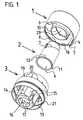
- FIG. 1is an exploded view of the individual parts of the first variant of the plastic spout with a rotating cap, a capsule, and a screw-on nozzle with opening sleeve shown separately, viewed diagonally from below.
- FIG. 2is an exploded view of individual parts of this first variant of the plastic spout with a rotating cap, a capsule, and a screw-on nozzle with opening sleeve shown separately, viewed diagonally from above.
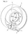
- FIG. 3is a perspective view of the rotating cap viewed diagonally from below in a magnified view.
- FIG. 4is an exploded view of the individual parts of this first variant of the plastic spout with a rotating cap, a capsule, and a screw-on nozzle with opening sleeve shown separately, viewed laterally.
- FIG. 5is a cross-sectional view of the individual parts taken longitudinally along the axis of rotation of the rotating cap, of the capsule, and of the screw-on nozzle with opening sleeve.
- FIG. 6is an exploded view of the individual parts of a second variant of the plastic spout with a rotating cap, a capsule, a screw-on nozzle and a container bottle, viewed from the side, aligned on their common axis.
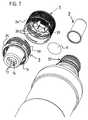
- FIG. 7is an exploded view of the individual parts of the plastic spout as per FIG. 6 .
- FIG. 8is a cross-sectional view of this plastic spout mounted on a container with the container nozzle required for spouting, taken longitudinally along the axis of rotation.
- FIG. 9is a cross-sectional view of the rotating cap and the capsule of the plastic spout, taken longitudinally along the axis of rotation.
- FIG. 10is an exploded view of the rotating cap with the guarantee tape and the associated screw-on nozzle viewed diagonally from above.
- FIG. 11is a perspective view of the rotating cap with the guarantee tape viewed from below.
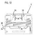
- FIG. 12is a cross-sectional view of the rotating cap with the guarantee tape viewed from the side.
- FIG. 13is an exploded view of the individual parts of a third variant of the plastic spout in the form of a sports or drink closure where the individual parts are aligned on their common axis.
- FIG. 14is a perceptive view of the opening sleeve for the capsule belonging to the plastic spout as per FIG. 13 , viewed diagonally from below.
- FIG. 15is a perspective view of the opening sleeve for the capsule belonging to the plastic spout as per FIG. 13 , viewed diagonally from above.
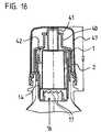
- FIG. 16is a cross-sectional view of the plastic spout as per FIG. 13 taken along its axis, in a mounted and closed, but not yet opened state.
- FIG. 17is a cross-sectional view of the plastic spout as per FIG. 13 taken along its axis, with the protective cap removed, before the dispensing of the substance in the capsule.
- FIG. 18is a cross-sectional view of the plastic spout as per FIG. 13 taken along its axis, after pressing down the stopper and thus opening the capsule and dispensing its contents in the container, however, in the closing position of the drinking nozzle.
- FIG. 19is a cross-sectional view of the plastic spout as per FIG. 13 taken along its axis, after pressing down the stopper and thus opening the capsule and dispensing its contents in the container, now in the open position of the drinking nozzle.
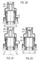
- FIG. 20is a cross-sectional view of the plastic spout as per FIG. 13 with the drink nozzle in this close position having an extended design.
- FIG. 21is a cross-sectional view of the plastic spout as per FIG. 20 with the drinking nozzle in the open position.
- FIG. 22is a cross-sectional view of the plastic spout as per FIG. 20 with the drinking nozzle in the open position, but rotated by a few angular degrees, so that the path of the liquid flowing out is visible.
- a common feature of all of the variants of the spout presented hereis that they contain a capsule with a separate substance.
- the substancemay be a liquid, a solid such as a powder, or any substantially flowable substance.
- the capsuleis opened when the spout is opened for the first time such that the substance falls down in the container lying below it.
- this capsuleis always arranged in an overturned position inside the spout. This means that the fixed base of the capsule lies on the top and its open side, sealed with a sealing foil, lies on the bottom.
- the capsuleis present inside the container nozzle or at least protrudes inside it to a large part.
- the lower edge of the spoutgenerally lies below the upper margin of the container nozzle or the container neck.
- this foilis automatically pierced or cut with a special opening device such that the contents of the capsule fall down in the container.
- this opening devicemay be inside the cap or the screw-on nozzle and is pushed downwards in a translatory way and is pressed over the sealing foil.
- the capsuleis pushed downwards by means of a rotating movement along a helix such that its sealing foil is then cut after being pierced by the stationary opening device upon a further rotary movement along the helix.
- FIG. 1shows the individual parts of the first variant of this plastic spout with a rotating cap 1 , a capsule 2 , and a screw-on nozzle 3 with an opening sleeve 14 .
- the partsmay be made from plastics, metallics, or any other convenient material.
- On one side of its peripheral wallhas a bulge 4 .
- There is a shear pin 5 in this bulge 4that protrudes a little above the bulge 4 and which acts as the tamperproof guarantee. Below this one can see the cylindrical capsule 2 .
- the capsule 2is open on the bottom and is sealed with a sealed foil 6 after it is filled.
- a helical collar 7that acts as a sliding curve, as will be explained later.
- the capsule 2can be inserted with its base 8 forward into a guide sleeve 9 inside the cap 1 and fixed in a concentric position to the cap 1 .
- the upper part of the capsule 2then lies in the inside of this guide sleeve 9 on the cap base, within which a guide sleeve 28 with a helical margin 10 is formed.
- the helical collar 7closes so as to form the sliding curve at the capsule 2 in a form-fitting way to the helical margin 10 of this guide sleeve 28 inside the guide sleeve 9 .
- the capsule 2At the lower end of the capsule 2 , this runs out in a laterally projecting edge 11 that has several straight sections 12 on the outside around its periphery. Below the capsule 2 , the screw-on nozzle 3 can be seen. On its lower inner side is an inner thread 13 , with which it can be screwed on the outer thread of a container nozzle.
- the containermay be a bottle made of glass or plastic. Likewise, the container may be a plastic container, a carton, a steel canister with plastic nozzles, and the like.
- an opening sleeve 14runs concentrically and is connected with the upper margin of the screw-on nozzle 3 on the top with a material bridge.
- This opening sleeve 14shows, in the given example, several plane side bands 15 .
- the capsule 2thus can be inserted in the opening sleeve 14 from the top in such a way that it is straight or the plane sections 12 on its lower projecting edge 11 lie opposite these plane side bands 15 of the opening sleeve 14 . In this way, the capsule 2 is protected against a slipping inside the opening sleeve 14 and can move in only a translatory way along the axis of rotation of the screw-on nozzle 3 .
- the opening sleeve 14shows a piercing and cutting device 16 with piercing and cutting teeth 17 projecting upward on the inner side of the opening sleeve 14 .
- the cap 1is forced on to the screw-on nozzle from the top under inclusion of the filled capsule 6 and sealed on the lower side with the sealing foil 6 .
- a groove 18runs along its lower edge.
- the screw-on nozzleforms a collar 19 on which radial outstanding cams 20 are formed. The cap 1 thus can be pressed on these cams 20 with its inner lying groove 18 , which then snap in the groove 18 .
- the cap 1is held firmly on the screw-on nozzle 3 , but can be rotated thereon.
- the rotating position of the cap 1is thereby selected in such a way that its shear pin 5 engages in a corresponding accommodation hole 21 on the outer side of the screw-on nozzle 3 .
- FIG. 2shows the parts of this first variant of the plastic spout with the rotating cap 1 , the capsule 2 , and the screw-on nozzle 3 with the opening sleeve 14 , seen diagonally from above.
- the bulge 4 at the cap margin with the shear pin 5 projecting downwardBelow the rotating cap 1 , the overturned capsule 2 is shown.
- the helical collar 7 of the cap base 8forms a slide curve that acts together with the helical margin 10 of the guide sleeve 28 inside the cap 1 for opening the capsule 2 .
- This guide sleeve 28can be seen in FIG. 1 .
- the radial projecting edge 11can be seen, which shows straight or plane sections 12 .
- each of theseshows a nose 23 which fit in the groove 18 on the inner side of the cap wall.
- the shear pin 5 at the lower edge of the cap edgefits into the opening 21 on the outside at the screw-on nozzle 3 .
- the tamperproof guaranteeis provided that upon rotating the cap 1 placed on the screw-on nozzle 3 , the shear pin 5 fitting in this opening 21 breaks.
- the opening 21includes a weak point on its right side that is pierced by the pin 5 that acts as a powerful bolt.
- the capsule 2can thus be placed in the screw-on nozzle 3 or in the opening 14 , so that its flat margins 12 on the edge 11 lie opposite to the plane sections 15 inside the opening sleeve 14 . It is then held firmly inside the opening sleeve 14 . In the lower area of the opening sleeve 14 , one can see the piercing and cutting teeth 17 projecting upward.
- a material bridge 22is present that carries the opening sleeve 14 freely hanging inside the screw-on nozzle 3 . This bridge forms a peripheral groove 24 .
- FIG. 3shows the rotating cap 1 diagonally from below in a magnified view.
- the handle 27that is formed between the outer wall of the cap 1 and the sleeve 9 and within which the guide sleeve 28 is formed with its helical outer margin 10 .
- This handle 27runs in two cams 30 , 31 aligned in axial direction and separated by a slit 29 .
- the inner cams 30slide along the inner limiting wall of the groove 24 while the outer cams 31 slide over the barbs 25 at the outer limiting wall of the groove 24 .
- the slit 29 between both the cams 30 , 31allows the cam 31 to yield a little against the center of the cap 1 and hence maneuver above the barbs 25 .
- the cam 31then jumps back behind each barb 25 and slides again along the length of the outer limiting wall of the groove 24 until the handle 27 finally comes to a stop at the cross-plate 26 in the groove 24 .
- the shear pin 5 in the bulge 4as well as the guide sleeve 28 with two sections of helical edges 10 .
- the radial ribs 32 on the base of the capare used for positioning the capsule 2 when it is inserted with its base on the front inside the cap. The base of the capsule then stands on these ribs 32 .
- FIG. 4shows the individual parts of this first variant of the plastic spout with the rotating cap 1 , the capsule 2 , and the screw-on nozzle 3 with an enclosed opening sleeve 14 displayed separately.
- the helical collars 7fit over the capsule 2 .
- the capsule 2disappears with the assembly of the spout inside the screw-on nozzle 3 .
- the plane sections 12 and their protruding edge 11are led along the plane sections 15 inside the opening sleeve 14 and held firmly therein. In this position, the sealing foil 6 of the capsule is present just above the piercing and cutting teeth 17 at the lower edge of the opening sleeve 14 .
- the capsule 2must remain in the same rotational position within the opening sleeve 14 while the cap 1 rotates around it.
- the helical edges 10 of the guide sleeve 28 inside the cap 1act on the slide curves of the capsule 2 and push the capsule 2 in a translatory movement downwards within the opening sleeve 14 .
- the sealing foil 6 of the capsule 2is pressed above the piercing and cutting teeth 17 present around the opening sleeve 14 .
- the piercing and cutting teeththus pierce the foil 6 along its marginal area and cut it such that that the contents of the capsule fall into the container.
- FIG. 5shows the parts of this spout assembled, in a cross-section along the axis of rotation of the rotating cap 1 , the capsule 2 , and the screw-on nozzle 3 with the opening sleeve 14 .
- the nozzle 3is screwed on a container nozzle 33 .
- this displayone sees how the capsule 2 with its helical collar 7 lies as the slide curves 7 at the helical edges 10 of the guide sleeve 28 . When the cap is rotated, these edges 10 are rotated over the slide curves at the capsule 2 and force the capsule 2 to move downwards.
- the capsule 2is thus pushed downwards within the opening sleeve 14 and its sealing foil 6 is thereby pressed over the piercing and the cutting device 16 so as to pierce the foil and cut it.
- the contents of the capsulethen fall in the container.
- the cap 1is now rotated further, which requires a large torque, then the nozzle 3 is loosened out from the external thread of the container nozzle 33 until the complete spout made of the cap 1 , the capsule 2 , and the nozzle 3 is removed from the container.
- the containeris then ready for its contents to be poured out, which is now mixed with the substance of capsule 2 .
- the spout with the screw-on nozzle 3can be screwed back again on the container nozzle 33 like a conventional threaded cap.
- FIG. 6A second embodiment variant of this plastic spout is shown in FIG. 6 .
- the container nozzle 33is designed here as a threaded nozzle with a normal outer thread running clockwise.
- the screw-on nozzle 3is rotated and screwed on this threaded nozzle in a clockwise direction.
- the corresponding threaded nozzleshows a counter-clockwise inner thread.
- the screw-on nozzle 3 of this second embodimenton shows an outer thread 48 running counter-clockwise.
- the cap 1 with a counter-clockwise threadis screwed on this outer thread from top in a counter-clockwise movement until a stop is reached that can be removed. This is formed by the fact that the cap 1 shows a guarantee tape 34 at its lower edge formed by fine material bridges.
- This guarantee tape 34finds a stop on the protruding collar 35 of the nozzle 3 .
- the screw nozzle 3is connected on its margin with the upper margin of an opening sleeve 14 running coaxially to it and having a small diameter via a radial bridge.
- This opening sleeve 14fits in the inside of the container nozzle 33 .
- the capsule 2In the lower side of the cap 1 , the capsule 2 at first opens on its downside, fills separately with a substance, and thereafter sealed with a foil 6 that is pushed inside and held firmly.
- This capsule 2can be formed directly on the base of the cap 1 .
- the capsule 2By overturning the cap 1 , the capsule 2 is filled and sealed.
- the spoutis mounted on the container nozzle 33 , then this capsule 2 protrudes on the inside of the container nozzle 33 , such that the sealing foil 6 of the capsule 2 lies just above the piercing and cutting device.
- With the removal of the guarantee tape 34there arises a gap between the lower edge of the cap 1 and the protruding collar 35 at the nozzle 3 .
- the cap 1can be screwed further downwards by a rotation in the counter-clockwise direction.
- the capsule 2rotates with the cap 1 and is thus rotated downwards over the piercing and cutting device so as to pierce and cut the foil 6 .
- the contents of the capsulefall into the container.
- the cap 1hits with its lower edge on the collar 35 of the nozzle 3 and cannot be screwed down any further. If the capsule 1 is rotated further in the counter-clockwise direction with additional torque, it then takes the nozzle 3 along with it and is loosened out from the thread of the container nozzle 33 .
- the complete spout together with the capsule 1 and the nozzle 3is thus loosened out from the container nozzle 33 and removed.
- the containeris ready for pouring out the contents now mixed with the substance.
- FIG. 7shows a perspective view of the individual parts of this spout, in a view seen diagonally from below.
- the guarantee tape 34 running aroundcan be seen.
- On the right near the cap 1is the capsule 2 with the sealing foil 6 .
- the capsule 2 with its openingis first filled and aligned upward and thereafter the sealing foil 6 is sealed or welded such that the capsule 2 is sealed.
- the capsule 2is then mounted in an overturned position in the cap 1 , i.e., with the foil 6 downwards and aligned with its base in the direction of the open side of the cap.
- the nozzle 3can be seen below the cap 1 .
- the opening sleeve 14protrudes out of the nozzle 3 from below.
- the capsule 2comes to lie in the inside of this sleeve 14 from the top. One can see the piercing and the cutting device 16 .
- To the right near the nozzle 3the container is shown with the related container nozzle 33 .
- FIG. 8shows this spout mounted as per FIG. 7 , in a cross-section along its axis of rotation.
- the nozzle 3that is connected on with the opening sleeve 14 via the radial bridge 22 .
- This opening sleeve 14is longer than the nozzle 3 and protrudes out from the same.
- On its lower edge, itcarries the piercing and the cutting device 16 connected with it in one piece. This forms at least one upward tooth and one slightly aligned cutting tooth 37 .
- the guarantee tape 34 of the cap 1lies on the collar 35 at the nozzle 3 .
- the straight dashed line yshows the position of the upper margin of the container nozzle 33 and the straight dashed line x shows the position of the lower edge 11 of the inserted capsule 2 with its sealing foil 6 .
- this lower edge 11lies clearly below the upper margin of the container nozzle 33 .
- the capsule 2is integrated in the inside of the container nozzle 33 such that it does not make the spout any bigger than a usual rotating or lid cap. If the guarantee tape 34 is now torn away, then the rotating cap 1 first can be screwed further downwards by a left movement. It takes along with it the capsule 2 downwards, rotates it along with it, and finally presses it in a rotating way with its foil 6 over the piercing and cutting device 16 . The foil 6 is thus pierced and cut with the rotating movement of the cutting tooth 37 . This opening process goes on until the lower edge of the cap 1 at the collar 35 is present on the nozzle 3 .
- FIG. 9This situation with the cut foil piece 6 is shown in FIG. 9 .
- the cap 1now finds a stop at the collar 35 . If the cap is now rotated further left out of this position, then it takes the nozzle 3 forcefully along with it, whereby the same is loosened out from the container nozzle 33 . However, the entire plastic spout is now loosened from the container nozzle 33 together with the now empty capsule 2 . The spout can be screwed again on to this container nozzle such that the container can be sealed airtight again.
- FIG. 10shows the cap 1 with its guarantee tape 34 at the lower edge of the cap 1 .
- This guarantee tape 34is fixed in the normal way via a few material bridges or via a continuous thin point 38 as a predetermined breaking point at the lower cap margin.
- a number of windows 49are distributed in length along the periphery.
- thisforms a gripping surface 50 which can be folded outside for tearing away the guarantee tape.
- the collar 35can be seen. This forms radial projections 51 , protruding outwards, and bevelled at its upper side.
- the projections 51fit in the window 49 when the cap 1 is set such that the cap 1 is safeguarded on all sides on the nozzle 3 .
- the height of the spoutcan be reduced vis-à-vis a solution in which the guarantee tape 34 is present with its lower edge on a projection.
- a radial cam 52is formed that fits in the clearance 53 at the lower edge of the guarantee tape 34 .
- the cam 52serves as an additional safeguard against rotation.
- FIG. 11the cap 1 is depicted as shown from below.
- FIG. 12shows the cap 1 seen from the side in a cross-section through its rotating axis.
- One recognises the retaining ring 39which is formed at the inner side of the cap lid, as well as ribs 36 formed radially inwards.
- the guarantee band 34can be seen below the cap 1 , which is held at the lower cap margin via the material bridges or a continuous thin point 38 .
- FIG. 13shows a third embodiment of the plastic spout in the form of a sports or drink closure.
- the individual partsare dismantled and showed in perspective view. The individual parts are thereby aligned on their common axis.
- the spoutincludes six parts.
- the part acting as the cap 1is designed as a drink closure.
- the cap 1forms a drink nozzle 40 that cooperates with a coaxially arranged stopper 41 of another part that acts as the screw-on nozzle 3 . Inside this nozzle, a number of ribs 42 are aligned radially inwards.
- the capsule 2 with its capsule base, i.e. with its sealing foil 6 downward,is held fixed.
- the cap 1shows a collar 43 that runs above in the drink nozzle 40 and forms against it a sleeve 44 .
- This sleeve 44is positioned over on the nozzle 3 via a guide nozzle 45 , which is fixed in a sealing way on the container nozzle 33 as shown in the example.
- Within this guide nozzle 45is an opening sleeve 14 with clearances 46 running axially in the outer wall.
- a piercing and cutting device 16At the lower end of this opening sleeve 14 is a piercing and cutting device 16 with upwardly aligned piercing and cutting teeth 17 .
- the capsule 2 with its sealing foil 6is set downward in the opening sleeve against the piercing and cutting device 14 such that when the stopper 41 is pressed down, the capsule 2 with its foil 6 is pressed against the piercing and cutting unit 16 .
- FIG. 14shows the receiving sleeve 14 . At its lower edge, one can see the piercing and the cutting device 16 . Outside on the opening sleeve 14 , a number of channels 46 are present such that the liquid can flow out when the drink spout is opened. In FIG. 15 , one sees the opening sleeve 14 from the top. Here one can see the individual teeth 17 of the piercing and cutting device 16 .
- FIG. 16shows the plastic spout in the mounted state in the initial position.
- a protective cap 47also is placed over the cap 1 .
- the stopper 41protrudes through the opening of the mouthpiece 40 and seals this opening.
- the capsule 2 inside the opening sleeve 14is inserted from below and is held on the top by the ribs 42 and is sealed by the sealing foil 6 on the bottom. Below the foil 6 of the capsule 2 , the piercing and the cutting device 16 formed at the lower end of the opening sleeve 14 is present.
- the protective cap 47is first removed as shown in FIG. 17 . One can now press with a finger on the stopper 41 .
- the capsule 2is pressed downwards in the opening sleeve 14 and its foil 6 is pressed over the piercing and cutting device.
- the foil 6is thereby pierced and cut as is shown in FIG. 18 .
- the capsule 2is now open and its content can now flow down into the container.
- the drink nozzle 40here is already pulled upwards in a locking position by about 4 mm or so. In this position, the stopper 41 closes the opening in the drink nozzle 40 .
- the cap 1For opening the drink spout, the cap 1 must be pulled further up until the topmost locking position, which is then pulled out by a total of about 6 mm or so. This is shown in FIG. 19 . In this position, the spout is ready to be set with the drink nozzle 40 at the mouth. By pushing back the drink nozzle 40 , the spout can be sealed closed again.
- FIG. 20shows this spout with a somewhat longer designed drink nozzle 40 in the closed position.
- the drink nozzle 40is pushed back so far that the stopper 41 projects in the opening and closes it.
- FIG. 21shows this drink nozzle 40 in the open position.
- FIG. 22shows a position rotated by a few degrees along the axis such that the liquid flowing out is shown by arrows.
- the liquidflows along the clearances 46 in the opening sleeve 14 , reaches the guide nozzles 45 , flows in to the stopper 41 , and finally flows outside through the opening in the drink nozzle 40 .
Landscapes
- Engineering & Computer Science (AREA)
- Mechanical Engineering (AREA)
- Closures For Containers (AREA)
Abstract
Description
Claims (13)
Priority Applications (16)
| Application Number | Priority Date | Filing Date | Title |
|---|---|---|---|
| US11/686,985US8276748B2 (en) | 2007-03-16 | 2007-03-16 | Ingredient release spout |
| US12/016,406US8443969B2 (en) | 2007-03-16 | 2008-01-18 | Ingredient release spout |
| CA2679472ACA2679472C (en) | 2007-03-16 | 2008-03-07 | Ingredient release spout |
| CN2008800082502ACN101631725B (en) | 2007-03-16 | 2008-03-07 | Ingredient release spout |
| PCT/US2008/056128WO2008115709A1 (en) | 2007-03-16 | 2008-03-07 | Ingredient release spout |
| JP2009553694AJP5576128B2 (en) | 2007-03-16 | 2008-03-07 | Material release spout |
| ES08731601.4TES2441442T3 (en) | 2007-03-16 | 2008-03-07 | Pouring device for the release of ingredients and method of releasing an ingredient into a container |
| MX2009009397AMX2009009397A (en) | 2007-03-16 | 2008-03-07 | Ingredient release spout. |
| BRPI0808830-6ABRPI0808830B1 (en) | 2007-03-16 | 2008-03-07 | INGREDIENT RELEASE NOZZLE AND METHOD TO RELEASE AN INGREDIENT WITHIN A CONTAINER |
| EP08731601.4AEP2125554B1 (en) | 2007-03-16 | 2008-03-07 | Ingredient release spout and method of releasing an ingredient into a container |
| TW097108524ATWI478850B (en) | 2007-03-16 | 2008-03-11 | Ingredient release spout |
| CL2008000742ACL2008000742A1 (en) | 2007-03-16 | 2008-03-13 | Ingredient dispensing mouth, comprising a cap, an ingredient capsule, a capsule housing containing the ingredient capsule, and a base; and method of releasing an ingredient into a container. |
| ARP080101079AAR065766A1 (en) | 2007-03-16 | 2008-03-14 | SPITA TO RELEASE AN INGREDIENT |
| ZA200906431AZA200906431B (en) | 2007-03-16 | 2009-09-15 | Ingredient release spout |
| US13/039,457US9592940B2 (en) | 2007-03-16 | 2011-03-03 | Ingredient release spout |
| JP2014077832AJP2014139094A (en) | 2007-03-16 | 2014-04-04 | Ingredient release spout |
Applications Claiming Priority (1)
| Application Number | Priority Date | Filing Date | Title |
|---|---|---|---|
| US11/686,985US8276748B2 (en) | 2007-03-16 | 2007-03-16 | Ingredient release spout |
Related Child Applications (1)
| Application Number | Title | Priority Date | Filing Date |
|---|---|---|---|
| US12/016,406Continuation-In-PartUS8443969B2 (en) | 2007-03-16 | 2008-01-18 | Ingredient release spout |
Publications (2)
| Publication Number | Publication Date |
|---|---|
| US20080223485A1 US20080223485A1 (en) | 2008-09-18 |
| US8276748B2true US8276748B2 (en) | 2012-10-02 |
Family
ID=39761460
Family Applications (1)
| Application Number | Title | Priority Date | Filing Date |
|---|---|---|---|
| US11/686,985Expired - Fee RelatedUS8276748B2 (en) | 2007-03-16 | 2007-03-16 | Ingredient release spout |
Country Status (2)
| Country | Link |
|---|---|
| US (1) | US8276748B2 (en) |
| ZA (1) | ZA200906431B (en) |
Cited By (17)
| Publication number | Priority date | Publication date | Assignee | Title |
|---|---|---|---|---|
| US20070280042A1 (en)* | 2004-09-29 | 2007-12-06 | Yoshino Kogyosyo Co., Ltd. | Container for mixing two liquids and the like |
| US8640865B2 (en)* | 2012-05-01 | 2014-02-04 | William Smart | Cap for storing materials separate from a body of liquid and facilitating subsequent mixing of the materials and the liquid |
| WO2014165983A1 (en)* | 2013-04-11 | 2014-10-16 | Bottlecap Holdings Ltd. | Dispenser having pierceable membrane |
| US20150129439A1 (en)* | 2011-05-16 | 2015-05-14 | Bottlecap Holdings Ltd. | Dispenser for dispensing material into a container |
| US9604765B2 (en) | 2013-03-14 | 2017-03-28 | Ahhmigo, Llc | Locking cap device and methods |
| AT518459A1 (en)* | 2016-03-18 | 2017-10-15 | Theuretzbacher Alfred | Capsule filling system |
| WO2017218279A1 (en)* | 2016-06-14 | 2017-12-21 | Pepsico, Inc. | Beverage system including a removable piercer |
| US9919860B2 (en) | 2012-05-15 | 2018-03-20 | Yaacov Dabah | Cap device and methods |
| US20180118428A1 (en)* | 2015-04-27 | 2018-05-03 | Microgaia Biotech, S.L. | Mixing stopper |
| US9975684B1 (en)* | 2013-12-27 | 2018-05-22 | Mary Lisa Dvorak | Interactive dispensing bottle cap |
| US10494164B2 (en) | 2016-03-09 | 2019-12-03 | Fifth Third Bank, an Ohio Banking | Dispensable containment vessel and dispensing system |
| US10676261B2 (en) | 2017-09-07 | 2020-06-09 | Silgan White Cap LLC | Closure assembly |
| US11235920B2 (en) | 2018-06-08 | 2022-02-01 | Pepsico, Inc. | Beverage ingredient pod |
| US11390516B2 (en) | 2020-05-08 | 2022-07-19 | Illinois Tool Works Inc. | Tap assembly |
| US20220281660A1 (en)* | 2021-03-04 | 2022-09-08 | Psimos, Inc. | Reusable dispenser lid |
| US20230089964A1 (en)* | 2020-01-31 | 2023-03-23 | Fuji Seal International, Inc. | Package body for pouch container and pouch container package |
| US11878903B2 (en) | 2020-06-11 | 2024-01-23 | Illinois Tool Works Inc. | Tap assembly |
Families Citing this family (15)
| Publication number | Priority date | Publication date | Assignee | Title |
|---|---|---|---|---|
| ITVI20070036A1 (en)* | 2007-02-06 | 2008-08-07 | Taplast Spa | DISPENSER, TANK FOR SUCH A DEVICE AND ITS SYSTEM FOR PREPARING A BEVERAGE |
| US9592940B2 (en)* | 2007-03-16 | 2017-03-14 | The Coca-Cola Company | Ingredient release spout |
| US20110168620A1 (en)* | 2010-01-13 | 2011-07-14 | Barry Askinasi | Apparatus and Method for Coating Diatomaceous Earth Filter Grids |
| US8141700B2 (en) | 2010-05-28 | 2012-03-27 | Tap the Cap, Inc. | Bottle cap for dispersing powdered supplement in situ |
| US8083055B2 (en) | 2010-05-28 | 2011-12-27 | Tap the Cap, Inc. | Dispensing cap system for beverage bottles |
| TWM399845U (en)* | 2010-07-26 | 2011-03-11 | Taiwan Vertex Production Corp | Rotary water stop bottle cap |
| USD672237S1 (en) | 2011-01-11 | 2012-12-11 | Tap the Cap, Inc. | Bottle cap for powdered supplement |
| JP6041108B2 (en)* | 2011-06-21 | 2016-12-14 | ベヴァスイス アーゲー | Fillable stopper with push button for release |
| GB2501138B (en)* | 2012-04-11 | 2014-07-30 | Tamm Inc | Removable bottle cap assembly |
| US10093918B2 (en) | 2014-06-04 | 2018-10-09 | Lucigen Corporation | Sample collection and analysis devices |
| WO2016106433A1 (en)* | 2014-12-30 | 2016-07-07 | Moradi Consulting Gmbh | Discharging element in the form of a capsule for discharging additives into a liquid |
| ITUA20162141A1 (en)* | 2016-03-31 | 2017-10-01 | Bormioli Pharma Spa | CLOSING CAPS |
| US20190329948A1 (en)* | 2016-11-18 | 2019-10-31 | Seidel GmbH & Co. KG | Closure cap |
| AU2018301184B2 (en)* | 2017-07-11 | 2023-11-02 | Elixa Limited | Dispensing device |
| CN109941596B (en)* | 2019-03-15 | 2025-01-28 | 深圳市麦士德福科技股份有限公司 | A bottle cap |
Citations (60)
| Publication number | Priority date | Publication date | Assignee | Title |
|---|---|---|---|---|
| US2004018A (en) | 1934-10-24 | 1935-06-04 | Luke J Strauss | Beverage bottle cap |
| US2275567A (en) | 1933-11-03 | 1942-03-10 | Arthur E Smith | Container closure |
| US3326400A (en)* | 1965-10-23 | 1967-06-20 | Oreal | Two compartment container |
| GB1479370A (en) | 1973-08-31 | 1977-07-13 | Guala Di Piergiacomo E Roberto | Closure device for bottles |
| US4167228A (en) | 1976-05-05 | 1979-09-11 | Cheetham J J | Containers |
| US4195730A (en) | 1978-06-20 | 1980-04-01 | General Foods Corporation | Container having separate storage facilities for two materials |
| FR2453793A1 (en) | 1979-04-12 | 1980-11-07 | Oreal | Storage containers for solids and liquids - allows contents to be mixed when one container is screwed to other fitted with discharge nozzle and rupturable membrane |
| FR2569666A1 (en) | 1984-08-29 | 1986-03-07 | Oreal | DEVICE FOR KEEPING AT LEAST TWO PRODUCTS SEPARATELY FROM ONE ANOTHER AND MIXING THEM FURTHER, ESPECIALLY AT THE TIME OF USE |
| US4682689A (en)* | 1986-06-27 | 1987-07-28 | Clairol Incorporated | Dual compartment container |
| FR2616322A1 (en) | 1987-06-11 | 1988-12-16 | Cassin Jamet Nelly | Aseptic device for setting reactive components in solution |
| US5020690A (en)* | 1987-06-30 | 1991-06-04 | Toppan Printing Co., Ltd. | Pouring plug for liquid container |
| US5246142A (en) | 1991-09-26 | 1993-09-21 | Dipalma Elio | Device for storing two products separately and subsequently mixing them |
| US5292019A (en)* | 1990-12-04 | 1994-03-08 | L. Ring | Tamper evident cap and container |
| US5370222A (en) | 1992-06-11 | 1994-12-06 | Wella Aktiengesellschaft | Arrangement for mixing two components |
| US5396986A (en) | 1993-06-16 | 1995-03-14 | Special Metals Corporation | Mixing capsule having three tubular members |
| US5461867A (en) | 1994-05-31 | 1995-10-31 | Insta-Heat, Inc. | Container with integral module for heating or cooling the contents |
| US6098795A (en) | 1997-10-14 | 2000-08-08 | Mollstam; Bo | Device for adding a component to a package |
| US6138821A (en) | 1999-11-26 | 2000-10-31 | Hsu; Lily | Container device for separately enclosing two different substances |
| US6148996A (en) | 1997-02-28 | 2000-11-21 | Bormioli Rocco & Figlio S.P.A. | Package for keeping products separate before use |
| US6152296A (en) | 1998-11-06 | 2000-11-28 | Shih; Kuang-Sheng | Additive holder for a pet bottle |
| WO2001046035A1 (en) | 1999-12-20 | 2001-06-28 | Alcon Universal Ltd. | Container with two compartments and a mixing device |
| US6305575B1 (en) | 1998-07-20 | 2001-10-23 | Itw New Zealand Limited | Dispenser |
| WO2001083313A2 (en) | 2000-04-28 | 2001-11-08 | Gerald Hagop Alticosalian | Device for storing and releasing a substance |
| US6382462B1 (en)* | 1998-02-17 | 2002-05-07 | Elopak A.S. | Packaging |
| US6387073B1 (en) | 2000-12-06 | 2002-05-14 | Weiler Engineering, Inc. | Hermetically sealed container with medicament storing and dispensing insert |
| US6422412B1 (en)* | 1998-06-11 | 2002-07-23 | Tetra Laval Holdings & Finance, S.A. | Container with cap |
| US20020157970A1 (en) | 2001-04-26 | 2002-10-31 | Carlson Stephen G. | Beverage flavor dispensing cap |
| US20020179461A1 (en) | 1997-10-14 | 2002-12-05 | Bo Mollstam | Two-compartment container |
| US6527110B2 (en) | 2000-12-01 | 2003-03-04 | Brett Moscovitz | Device for storing and dispensing a substance by mating with a container and associated methods |
| US6533113B2 (en) | 2000-12-01 | 2003-03-18 | Brett Moscovitz | System, devices and methods for storing and mixing substances |
| US6571994B1 (en) | 2001-12-12 | 2003-06-03 | Portola Packaging, Inc. | Closure having rotatable spout and axially movable stem |
| EP1222122B1 (en) | 1999-10-22 | 2003-06-25 | Wella Aktiengesellschaft | Combination packaging |
| US20030132244A1 (en) | 2002-01-17 | 2003-07-17 | Jorg Birkmayer | Twist closure means for a container |
| US6644471B1 (en) | 2002-05-24 | 2003-11-11 | Michael R. Anderson | Dispensing capsule for a liquid container |
| US20030213709A1 (en) | 2002-05-16 | 2003-11-20 | Gibler Gregory A. | Beverage storage and discharge cap assembly |
| US20040200742A1 (en) | 2003-04-12 | 2004-10-14 | Cho Young Kook | Cap device for mixing different kinds of materials separately contained therein and in bottle |
| WO2004089777A2 (en) | 2003-04-02 | 2004-10-21 | NESTLE WATERS MANAGEMENT & TECHNOLOGY (Société Anonyme) | Capsule with a piercable cap, stopper and container provided with said capsule |
| US6854595B2 (en) | 2002-07-15 | 2005-02-15 | Danny Kiser | Container closure containing a mix |
| GB2405868A (en) | 2003-09-05 | 2005-03-16 | Li-Li Yehhsu | Two compartment container and closure for substances to be mixed |
| WO2005023667A1 (en) | 2003-09-09 | 2005-03-17 | Aron Joseph Clarkson | Dispensing closure |
| US20050167295A1 (en) | 2004-01-30 | 2005-08-04 | Emanuel Shenkar | Portion closure and method of using |
| US6945393B2 (en) | 2002-12-24 | 2005-09-20 | Young Kook Cho | Cap device for attachment to a container |
| US20050211579A1 (en)* | 2004-03-29 | 2005-09-29 | Masayuki Makita And Bzi Co., Ltd. | Bottle cap |
| WO2006035558A1 (en) | 2004-09-29 | 2006-04-06 | Yoshino Kogyosyo Co., Ltd. | Mixing vessel for two-part fluid or the like |
| WO2006037244A1 (en) | 2004-10-01 | 2006-04-13 | Belcap Ag | Capsule closure |
| WO2006046725A1 (en) | 2004-10-25 | 2006-05-04 | The Coca-Cola Company | Bottle cap |
| US20060108314A1 (en) | 2004-11-23 | 2006-05-25 | Cho Young K | Sanitary double cap allowing addition of adjunct to contents of a container |
| US7172095B2 (en) | 2003-04-18 | 2007-02-06 | Christopher John Marshall | Bottle closure containing beverage concentrate |
| US7175049B2 (en) | 2004-08-17 | 2007-02-13 | Hormel Foods, Llc | Dispensing cap |
| US20070045134A1 (en) | 2005-08-29 | 2007-03-01 | Steven Dvorak | Aqueous Solution of an Analgesic and a Dispenser Therefor |
| US20090242561A1 (en) | 2005-07-01 | 2009-10-01 | Vitalia International Pty Ltd. | Closure |
| US20090261000A1 (en) | 2006-04-12 | 2009-10-22 | Rene Epp | Container closure having a capsule inside it |
| US20090308831A1 (en) | 2008-06-13 | 2009-12-17 | Anderson Michael R | Pouch carton and container fitments for use with any ingredients |
| EP2181932A1 (en) | 2008-11-04 | 2010-05-05 | Seaquist Closures, L.L.C. | Liner piercing twist closure |
| EP1682443B1 (en) | 2003-10-27 | 2010-05-19 | Portola Packaging, Inc. | Twist-open closure having inclined frangible membrane |
| GB2466187A (en) | 2008-12-09 | 2010-06-16 | Adam David Smith | Bottle cap apparatus comprising a blister pack |
| US20100163442A1 (en) | 2005-12-12 | 2010-07-01 | Lee Jeong-Min | Cap assembly having storage chamber for secondary material with inseparable working member |
| EP2216262A1 (en) | 2007-10-30 | 2010-08-11 | Expansio Isotop, S.L. | Mixing lid for isotonic drinks |
| EP2114791B1 (en) | 2007-02-06 | 2010-09-15 | Taplast Spa | Dispensing device and corresponding system for preparing a drink |
| US20100237075A1 (en) | 2007-10-22 | 2010-09-23 | Wilhelm Rene | Sheet-material piercer for a container closure |
- 2007
- 2007-03-16USUS11/686,985patent/US8276748B2/ennot_activeExpired - Fee Related
- 2009
- 2009-09-15ZAZA200906431Apatent/ZA200906431B/enunknown
Patent Citations (70)
| Publication number | Priority date | Publication date | Assignee | Title |
|---|---|---|---|---|
| US2275567A (en) | 1933-11-03 | 1942-03-10 | Arthur E Smith | Container closure |
| US2004018A (en) | 1934-10-24 | 1935-06-04 | Luke J Strauss | Beverage bottle cap |
| US3326400A (en)* | 1965-10-23 | 1967-06-20 | Oreal | Two compartment container |
| GB1479370A (en) | 1973-08-31 | 1977-07-13 | Guala Di Piergiacomo E Roberto | Closure device for bottles |
| US4167228A (en) | 1976-05-05 | 1979-09-11 | Cheetham J J | Containers |
| US4294351A (en) | 1976-05-05 | 1981-10-13 | Cheetham J J | Containers |
| US4195730A (en) | 1978-06-20 | 1980-04-01 | General Foods Corporation | Container having separate storage facilities for two materials |
| FR2453793A1 (en) | 1979-04-12 | 1980-11-07 | Oreal | Storage containers for solids and liquids - allows contents to be mixed when one container is screwed to other fitted with discharge nozzle and rupturable membrane |
| FR2569666A1 (en) | 1984-08-29 | 1986-03-07 | Oreal | DEVICE FOR KEEPING AT LEAST TWO PRODUCTS SEPARATELY FROM ONE ANOTHER AND MIXING THEM FURTHER, ESPECIALLY AT THE TIME OF USE |
| US4682689A (en)* | 1986-06-27 | 1987-07-28 | Clairol Incorporated | Dual compartment container |
| FR2616322A1 (en) | 1987-06-11 | 1988-12-16 | Cassin Jamet Nelly | Aseptic device for setting reactive components in solution |
| US5020690A (en)* | 1987-06-30 | 1991-06-04 | Toppan Printing Co., Ltd. | Pouring plug for liquid container |
| US5292019A (en)* | 1990-12-04 | 1994-03-08 | L. Ring | Tamper evident cap and container |
| US5246142A (en) | 1991-09-26 | 1993-09-21 | Dipalma Elio | Device for storing two products separately and subsequently mixing them |
| US5370222A (en) | 1992-06-11 | 1994-12-06 | Wella Aktiengesellschaft | Arrangement for mixing two components |
| US5396986A (en) | 1993-06-16 | 1995-03-14 | Special Metals Corporation | Mixing capsule having three tubular members |
| US5461867A (en) | 1994-05-31 | 1995-10-31 | Insta-Heat, Inc. | Container with integral module for heating or cooling the contents |
| US6148996A (en) | 1997-02-28 | 2000-11-21 | Bormioli Rocco & Figlio S.P.A. | Package for keeping products separate before use |
| US6098795A (en) | 1997-10-14 | 2000-08-08 | Mollstam; Bo | Device for adding a component to a package |
| US20020179461A1 (en) | 1997-10-14 | 2002-12-05 | Bo Mollstam | Two-compartment container |
| US6382462B1 (en)* | 1998-02-17 | 2002-05-07 | Elopak A.S. | Packaging |
| US6422412B1 (en)* | 1998-06-11 | 2002-07-23 | Tetra Laval Holdings & Finance, S.A. | Container with cap |
| US6645419B2 (en) | 1998-07-20 | 2003-11-11 | Itw New Zealand Limited | Dispenser |
| US6305575B1 (en) | 1998-07-20 | 2001-10-23 | Itw New Zealand Limited | Dispenser |
| US6152296A (en) | 1998-11-06 | 2000-11-28 | Shih; Kuang-Sheng | Additive holder for a pet bottle |
| EP1222122B1 (en) | 1999-10-22 | 2003-06-25 | Wella Aktiengesellschaft | Combination packaging |
| US6138821A (en) | 1999-11-26 | 2000-10-31 | Hsu; Lily | Container device for separately enclosing two different substances |
| WO2001046035A1 (en) | 1999-12-20 | 2001-06-28 | Alcon Universal Ltd. | Container with two compartments and a mixing device |
| WO2001083313A2 (en) | 2000-04-28 | 2001-11-08 | Gerald Hagop Alticosalian | Device for storing and releasing a substance |
| US20020053524A1 (en) | 2000-04-28 | 2002-05-09 | Alticosalian Gerald Hagop | Device for storing and releasing a substance |
| US6763939B2 (en) | 2000-04-28 | 2004-07-20 | Gerald Hagop Alticosalian | Device for storing and releasing a substance |
| EP1278680A2 (en) | 2000-04-28 | 2003-01-29 | Gerald Hagop Alticosalian | Device for storing and releasing a substance |
| US6527110B2 (en) | 2000-12-01 | 2003-03-04 | Brett Moscovitz | Device for storing and dispensing a substance by mating with a container and associated methods |
| US6533113B2 (en) | 2000-12-01 | 2003-03-18 | Brett Moscovitz | System, devices and methods for storing and mixing substances |
| US6387073B1 (en) | 2000-12-06 | 2002-05-14 | Weiler Engineering, Inc. | Hermetically sealed container with medicament storing and dispensing insert |
| US20020157970A1 (en) | 2001-04-26 | 2002-10-31 | Carlson Stephen G. | Beverage flavor dispensing cap |
| US7017735B2 (en) | 2001-04-26 | 2006-03-28 | The Coca-Cola Company | Dispensing cap with capsule for container |
| US6571994B1 (en) | 2001-12-12 | 2003-06-03 | Portola Packaging, Inc. | Closure having rotatable spout and axially movable stem |
| US20030132244A1 (en) | 2002-01-17 | 2003-07-17 | Jorg Birkmayer | Twist closure means for a container |
| US20030213709A1 (en) | 2002-05-16 | 2003-11-20 | Gibler Gregory A. | Beverage storage and discharge cap assembly |
| US6840373B2 (en) | 2002-05-16 | 2005-01-11 | Gregory A Gibler | Beverage storage and discharge cap assembly |
| US6644471B1 (en) | 2002-05-24 | 2003-11-11 | Michael R. Anderson | Dispensing capsule for a liquid container |
| US6854595B2 (en) | 2002-07-15 | 2005-02-15 | Danny Kiser | Container closure containing a mix |
| US6945393B2 (en) | 2002-12-24 | 2005-09-20 | Young Kook Cho | Cap device for attachment to a container |
| WO2004089777A2 (en) | 2003-04-02 | 2004-10-21 | NESTLE WATERS MANAGEMENT & TECHNOLOGY (Société Anonyme) | Capsule with a piercable cap, stopper and container provided with said capsule |
| US6935493B2 (en) | 2003-04-12 | 2005-08-30 | Young Kook Cho | Cap device for mixing different kinds of materials separately contained therein and in bottle |
| US20040200742A1 (en) | 2003-04-12 | 2004-10-14 | Cho Young Kook | Cap device for mixing different kinds of materials separately contained therein and in bottle |
| US7172095B2 (en) | 2003-04-18 | 2007-02-06 | Christopher John Marshall | Bottle closure containing beverage concentrate |
| GB2405868A (en) | 2003-09-05 | 2005-03-16 | Li-Li Yehhsu | Two compartment container and closure for substances to be mixed |
| WO2005023667A1 (en) | 2003-09-09 | 2005-03-17 | Aron Joseph Clarkson | Dispensing closure |
| US20070023299A1 (en) | 2003-09-09 | 2007-02-01 | Clarkson Aron J | Dispensing closure |
| EP1682443B1 (en) | 2003-10-27 | 2010-05-19 | Portola Packaging, Inc. | Twist-open closure having inclined frangible membrane |
| US20050167295A1 (en) | 2004-01-30 | 2005-08-04 | Emanuel Shenkar | Portion closure and method of using |
| US20050211579A1 (en)* | 2004-03-29 | 2005-09-29 | Masayuki Makita And Bzi Co., Ltd. | Bottle cap |
| US7175049B2 (en) | 2004-08-17 | 2007-02-13 | Hormel Foods, Llc | Dispensing cap |
| WO2006035558A1 (en) | 2004-09-29 | 2006-04-06 | Yoshino Kogyosyo Co., Ltd. | Mixing vessel for two-part fluid or the like |
| US20070280042A1 (en)* | 2004-09-29 | 2007-12-06 | Yoshino Kogyosyo Co., Ltd. | Container for mixing two liquids and the like |
| WO2006037244A1 (en) | 2004-10-01 | 2006-04-13 | Belcap Ag | Capsule closure |
| WO2006046725A1 (en) | 2004-10-25 | 2006-05-04 | The Coca-Cola Company | Bottle cap |
| US20060108314A1 (en) | 2004-11-23 | 2006-05-25 | Cho Young K | Sanitary double cap allowing addition of adjunct to contents of a container |
| US20090242561A1 (en) | 2005-07-01 | 2009-10-01 | Vitalia International Pty Ltd. | Closure |
| US20070045134A1 (en) | 2005-08-29 | 2007-03-01 | Steven Dvorak | Aqueous Solution of an Analgesic and a Dispenser Therefor |
| US20100163442A1 (en) | 2005-12-12 | 2010-07-01 | Lee Jeong-Min | Cap assembly having storage chamber for secondary material with inseparable working member |
| US20090261000A1 (en) | 2006-04-12 | 2009-10-22 | Rene Epp | Container closure having a capsule inside it |
| EP2114791B1 (en) | 2007-02-06 | 2010-09-15 | Taplast Spa | Dispensing device and corresponding system for preparing a drink |
| US20100237075A1 (en) | 2007-10-22 | 2010-09-23 | Wilhelm Rene | Sheet-material piercer for a container closure |
| EP2216262A1 (en) | 2007-10-30 | 2010-08-11 | Expansio Isotop, S.L. | Mixing lid for isotonic drinks |
| US20090308831A1 (en) | 2008-06-13 | 2009-12-17 | Anderson Michael R | Pouch carton and container fitments for use with any ingredients |
| EP2181932A1 (en) | 2008-11-04 | 2010-05-05 | Seaquist Closures, L.L.C. | Liner piercing twist closure |
| GB2466187A (en) | 2008-12-09 | 2010-06-16 | Adam David Smith | Bottle cap apparatus comprising a blister pack |
Non-Patent Citations (1)
| Title |
|---|
| International Search Report of PCT/US2008/056128. |
Cited By (26)
| Publication number | Priority date | Publication date | Assignee | Title |
|---|---|---|---|---|
| US8714808B2 (en)* | 2004-09-29 | 2014-05-06 | Yoshino Kogyosho Co., Ltd. | Container for mixing two fluids |
| US20070280042A1 (en)* | 2004-09-29 | 2007-12-06 | Yoshino Kogyosyo Co., Ltd. | Container for mixing two liquids and the like |
| US9718598B2 (en) | 2004-09-29 | 2017-08-01 | Yoshino Kogyosho Co., Ltd. | Container for mixing two fluids |
| US20150129439A1 (en)* | 2011-05-16 | 2015-05-14 | Bottlecap Holdings Ltd. | Dispenser for dispensing material into a container |
| US8640865B2 (en)* | 2012-05-01 | 2014-02-04 | William Smart | Cap for storing materials separate from a body of liquid and facilitating subsequent mixing of the materials and the liquid |
| US9919860B2 (en) | 2012-05-15 | 2018-03-20 | Yaacov Dabah | Cap device and methods |
| US9604765B2 (en) | 2013-03-14 | 2017-03-28 | Ahhmigo, Llc | Locking cap device and methods |
| US10005599B2 (en) | 2013-04-11 | 2018-06-26 | Bottlecap Holdings Ltd. | Dispenser having pierceable membrane |
| WO2014165983A1 (en)* | 2013-04-11 | 2014-10-16 | Bottlecap Holdings Ltd. | Dispenser having pierceable membrane |
| US9975684B1 (en)* | 2013-12-27 | 2018-05-22 | Mary Lisa Dvorak | Interactive dispensing bottle cap |
| US20180118428A1 (en)* | 2015-04-27 | 2018-05-03 | Microgaia Biotech, S.L. | Mixing stopper |
| US10118748B2 (en)* | 2015-04-27 | 2018-11-06 | Microgaia Biotech, S.L. | Mixing stopper |
| US10494164B2 (en) | 2016-03-09 | 2019-12-03 | Fifth Third Bank, an Ohio Banking | Dispensable containment vessel and dispensing system |
| AT518459A1 (en)* | 2016-03-18 | 2017-10-15 | Theuretzbacher Alfred | Capsule filling system |
| AT518459B1 (en)* | 2016-03-18 | 2019-07-15 | Theuretzbacher Alfred | Capsule filling system |
| EP3468884A4 (en)* | 2016-06-14 | 2020-01-15 | Pepsico, Inc. | Beverage system including a removable piercer |
| WO2017218279A1 (en)* | 2016-06-14 | 2017-12-21 | Pepsico, Inc. | Beverage system including a removable piercer |
| US10610045B2 (en) | 2016-06-14 | 2020-04-07 | Pepsico, Inc. | Beverage system including a removable piercer |
| US10676261B2 (en) | 2017-09-07 | 2020-06-09 | Silgan White Cap LLC | Closure assembly |
| US11718457B2 (en) | 2017-09-07 | 2023-08-08 | Silgan White Cap LLC | Closure assembly |
| US11235920B2 (en) | 2018-06-08 | 2022-02-01 | Pepsico, Inc. | Beverage ingredient pod |
| US20230089964A1 (en)* | 2020-01-31 | 2023-03-23 | Fuji Seal International, Inc. | Package body for pouch container and pouch container package |
| US11390516B2 (en) | 2020-05-08 | 2022-07-19 | Illinois Tool Works Inc. | Tap assembly |
| US11878903B2 (en) | 2020-06-11 | 2024-01-23 | Illinois Tool Works Inc. | Tap assembly |
| US20220281660A1 (en)* | 2021-03-04 | 2022-09-08 | Psimos, Inc. | Reusable dispenser lid |
| US11834239B2 (en)* | 2021-03-04 | 2023-12-05 | Psimos, Inc. | Reusable dispenser lid |
Also Published As
| Publication number | Publication date |
|---|---|
| US20080223485A1 (en) | 2008-09-18 |
| ZA200906431B (en) | 2010-10-27 |
Similar Documents
| Publication | Publication Date | Title |
|---|---|---|
| US8276748B2 (en) | Ingredient release spout | |
| US8443969B2 (en) | Ingredient release spout | |
| US9592940B2 (en) | Ingredient release spout | |
| JP4987881B2 (en) | Sealing device with non-continuous circular cutting ring | |
| US20180044078A1 (en) | Bottle with bottle cap delivery system | |
| US6702161B2 (en) | Closure having rotatable spout and axially movable stem | |
| US20100140209A1 (en) | Universal closure apparatus with delivery system | |
| US7261226B2 (en) | Closure having rotatable spout and axially movable stem | |
| CN100584704C (en) | Flat self-opening closure | |
| JP4031276B2 (en) | Two-component mixing cap | |
| US20050279653A1 (en) | Device for dispensing material into a container | |
| KR20140017521A (en) | Bottle with dispensing device | |
| US20100044254A1 (en) | Beverage mix dispensing closure | |
| US20070102394A1 (en) | Closure device for a bottle | |
| US11180296B2 (en) | Doser cap for liquid container | |
| MXPA06008076A (en) | A capsule incorporating a doser and openable security cap, in particular for single-dose flagons. | |
| KR20140125343A (en) | Cap | |
| EP1907292B1 (en) | Closure device for a bottle | |
| GB2417941A (en) | Dispensing device for mixing two substances |
Legal Events
| Date | Code | Title | Description |
|---|---|---|---|
| AS | Assignment | Owner name:THE COCA-COLA COMPANY, GEORGIA Free format text:ASSIGNMENT OF ASSIGNORS INTEREST;ASSIGNORS:NYAMBI, SAMUEL OMBUKU;SEELHOFER, FRITZ;REEL/FRAME:019021/0978;SIGNING DATES FROM 20070312 TO 20070314 Owner name:THE COCA-COLA COMPANY, GEORGIA Free format text:ASSIGNMENT OF ASSIGNORS INTEREST;ASSIGNORS:NYAMBI, SAMUEL OMBUKU;SEELHOFER, FRITZ;SIGNING DATES FROM 20070312 TO 20070314;REEL/FRAME:019021/0978 | |
| AS | Assignment | Owner name:THE COCA-COLA COMPANY, GEORGIA Free format text:CORRECTIVE ASSIGNMENT TO CORRECT THE MIDDLE NAME OF 1ST ASSIGNOR. PREVIOUSLY RECORDED ON REEL 019021 FRAME 0978;ASSIGNORS:NYAMBI, SAMUEL OMBAKU;SEELHOFER, FRITZ;REEL/FRAME:020601/0653;SIGNING DATES FROM 20070312 TO 20070314 Owner name:THE COCA-COLA COMPANY, GEORGIA Free format text:CORRECTIVE ASSIGNMENT TO CORRECT THE MIDDLE NAME OF 1ST ASSIGNOR. PREVIOUSLY RECORDED ON REEL 019021 FRAME 0978. ASSIGNOR(S) HEREBY CONFIRMS THE OMBUKU SHOULD BE SPELT OMBAKU.;ASSIGNORS:NYAMBI, SAMUEL OMBAKU;SEELHOFER, FRITZ;SIGNING DATES FROM 20070312 TO 20070314;REEL/FRAME:020601/0653 | |
| STCF | Information on status: patent grant | Free format text:PATENTED CASE | |
| FEPP | Fee payment procedure | Free format text:PAYOR NUMBER ASSIGNED (ORIGINAL EVENT CODE: ASPN); ENTITY STATUS OF PATENT OWNER: LARGE ENTITY | |
| FPAY | Fee payment | Year of fee payment:4 | |
| MAFP | Maintenance fee payment | Free format text:PAYMENT OF MAINTENANCE FEE, 8TH YEAR, LARGE ENTITY (ORIGINAL EVENT CODE: M1552); ENTITY STATUS OF PATENT OWNER: LARGE ENTITY Year of fee payment:8 | |
| FEPP | Fee payment procedure | Free format text:MAINTENANCE FEE REMINDER MAILED (ORIGINAL EVENT CODE: REM.); ENTITY STATUS OF PATENT OWNER: LARGE ENTITY | |
| LAPS | Lapse for failure to pay maintenance fees | Free format text:PATENT EXPIRED FOR FAILURE TO PAY MAINTENANCE FEES (ORIGINAL EVENT CODE: EXP.); ENTITY STATUS OF PATENT OWNER: LARGE ENTITY | |
| STCH | Information on status: patent discontinuation | Free format text:PATENT EXPIRED DUE TO NONPAYMENT OF MAINTENANCE FEES UNDER 37 CFR 1.362 | |
| FP | Lapsed due to failure to pay maintenance fee | Effective date:20241002 |