US8276480B2 - Torque-adjusting drive mechanism for a propellable device - Google Patents
Torque-adjusting drive mechanism for a propellable deviceDownload PDFInfo
- Publication number
- US8276480B2 US8276480B2US12/402,306US40230609AUS8276480B2US 8276480 B2US8276480 B2US 8276480B2US 40230609 AUS40230609 AUS 40230609AUS 8276480 B2US8276480 B2US 8276480B2
- Authority
- US
- United States
- Prior art keywords
- torque
- drive
- assembly
- driveshaft
- driven element
- Prior art date
- Legal status (The legal status is an assumption and is not a legal conclusion. Google has not performed a legal analysis and makes no representation as to the accuracy of the status listed.)
- Active, expires
Links
- 230000007246mechanismEffects0.000titleclaimsabstractdescription60
- 238000000034methodMethods0.000claimsdescription15
- 238000005452bendingMethods0.000claimsdescription10
- 230000001141propulsive effectEffects0.000claimsdescription3
- 241001465754MetazoaSpecies0.000description3
- 230000015654memoryEffects0.000description3
- 208000027418Wounds and injuryDiseases0.000description2
- 230000009286beneficial effectEffects0.000description2
- 238000011960computer-aided designMethods0.000description2
- 230000006378damageEffects0.000description2
- 238000009826distributionMethods0.000description2
- 230000000694effectsEffects0.000description2
- 230000002708enhancing effectEffects0.000description2
- 230000001747exhibiting effectEffects0.000description2
- 239000000463materialSubstances0.000description2
- 230000000704physical effectEffects0.000description2
- 239000007787solidSubstances0.000description2
- 210000001072colonAnatomy0.000description1
- 238000004590computer programMethods0.000description1
- 238000010276constructionMethods0.000description1
- 230000006870functionEffects0.000description1
- 208000014674injuryDiseases0.000description1
- 230000003287optical effectEffects0.000description1
- 210000000813small intestineAnatomy0.000description1
- 230000001225therapeutic effectEffects0.000description1
Images


Classifications
- F—MECHANICAL ENGINEERING; LIGHTING; HEATING; WEAPONS; BLASTING
- F16—ENGINEERING ELEMENTS AND UNITS; GENERAL MEASURES FOR PRODUCING AND MAINTAINING EFFECTIVE FUNCTIONING OF MACHINES OR INSTALLATIONS; THERMAL INSULATION IN GENERAL
- F16H—GEARING
- F16H37/00—Combinations of mechanical gearings, not provided for in groups F16H1/00 - F16H35/00
- F16H37/02—Combinations of mechanical gearings, not provided for in groups F16H1/00 - F16H35/00 comprising essentially only toothed or friction gearings
- F16H37/06—Combinations of mechanical gearings, not provided for in groups F16H1/00 - F16H35/00 comprising essentially only toothed or friction gearings with a plurality of driving or driven shafts; with arrangements for dividing torque between two or more intermediate shafts
- F16H37/065—Combinations of mechanical gearings, not provided for in groups F16H1/00 - F16H35/00 comprising essentially only toothed or friction gearings with a plurality of driving or driven shafts; with arrangements for dividing torque between two or more intermediate shafts with a plurality of driving or driven shafts
- A—HUMAN NECESSITIES
- A61—MEDICAL OR VETERINARY SCIENCE; HYGIENE
- A61B—DIAGNOSIS; SURGERY; IDENTIFICATION
- A61B1/00—Instruments for performing medical examinations of the interior of cavities or tubes of the body by visual or photographical inspection, e.g. endoscopes; Illuminating arrangements therefor
- A61B1/00147—Holding or positioning arrangements
- A61B1/00156—Holding or positioning arrangements using self propulsion
- Y—GENERAL TAGGING OF NEW TECHNOLOGICAL DEVELOPMENTS; GENERAL TAGGING OF CROSS-SECTIONAL TECHNOLOGIES SPANNING OVER SEVERAL SECTIONS OF THE IPC; TECHNICAL SUBJECTS COVERED BY FORMER USPC CROSS-REFERENCE ART COLLECTIONS [XRACs] AND DIGESTS
- Y10—TECHNICAL SUBJECTS COVERED BY FORMER USPC
- Y10T—TECHNICAL SUBJECTS COVERED BY FORMER US CLASSIFICATION
- Y10T74/00—Machine element or mechanism
- Y10T74/19—Gearing
- Y10T74/19023—Plural power paths to and/or from gearing
- Y10T74/19074—Single drive plural driven
- Y10T74/19079—Parallel
Definitions
- This patent documentrelates generally to drive mechanisms, and more specifically, to torque-adjusting drive mechanisms for a propellable device.
- Drive mechanismscan be used to drive various objects.
- some endoscope systemsutilize a self-propellable device which helps carry an endoscope or other load.
- These self-propelled devicescan be driven by a driveshaft that rotates to turn one or more gears within a drive mechanism of the self-propellable device to drive the device.
- the rotation of the driveshaftcan result in undesired external torque on the device.
- FIG. 1illustrates an example of a schematic view of a torque-canceling or other torque-adjusting drive mechanism for use with a propellable device, the drive mechanism optionally configurable to result in a desired external device torque.
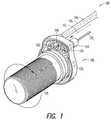
- FIG. 2illustrates an example of a propellable device connected to an electrical control unit.
- FIG. 3illustrates a schematic view of an example of a second possible configuration of a torque-canceling or other torque-adjusting drive mechanism for use with a propellable device, the drive mechanism optionally configurable to result in a desired external device torque.
- FIG. 4illustrates an example of a propellable device attached to an electrical control unit, the control unit including a separate element for controlling one or more drive torques transmitted to the device.
- FIG. 5illustrates an example of an embodiment of a propellable device that can be steered, in part, using an external device torque resulting from an imbalance of counter-rotating drive torques delivered to the device.
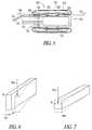
- FIG. 6illustrates an example of a structure exhibiting lateral deflection when subjected to a bending stress.
- FIG. 7illustrates an example of a structure exhibiting little to no lateral deflection when subjected to a bending stress.
- FIG. 1illustrates an example of a torque-canceling or other torque-adjusting drive mechanism 100 for use by a propellable device, such as one or more of the propellable devices described in commonly-owned: U.S. Pat. No. 6,971,990, entitled “PROPULSION MECHANISM FOR ENDOCOPIC SYSTEMS,” U.S. patent application Ser. No. 11/260,342 entitled “SELF-PROPELLABLE ENDOSCOPIC APPARATUS AND METHOD,” and U.S. patent application Ser. No. 11/825,528 also entitled “SELF-PROPELLABLE ENDOSCOPIC APPARATUS AND METHOD,” each of which is incorporated by reference herein in its entirety, including its disclosure of a propellable device.
- the propellable devices described in the foregoing patent documentscan include a permeable or impermeable self-enclosed tube, sized and shaped to fit within and engage a cavity, such as a human or animal body cavity.
- the tubecan have an inner surface defining an enclosed region and an outer surface that is configured to turn outward to engage a wall of the cavity and turn inward to encompass a central region defining a concentric longitudinal path.
- the apparatuscan further include an attachment coupled in proximity to the tube.
- the attachmentcan be configured to secure a load (e.g., an accessory) such as, for example, at a location at least partially in the central region.
- the tubeUpon securing of the load, the tube can be powered to provide movement relative to the cavity, thereby facilitating movement of the load with respect to the cavity in at least one of a forward or reverse direction generally along the longitudinal path.
- the torque-canceling or torque-adjusting drive mechanism 100 configured for powering a tube of a propellable devicecan include two flexible, solid wire driveshafts 102 , 104 , such as for supplying mechanical power from an external location to the propellable device when the propellable device is located within a cavity, such as a human body cavity, for example.
- the driveshafts 102 , 104can comprise one or more non-solid, flexible components also capable of delivering drive torque, such as wound cables, for example.
- Drive mechanism 100also includes drive assembly 105 including a frame 126 and a driven element 110 .
- Driveshafts 102 , 104are operatively coupled to drive assembly 105 to apply propulsive drive torque to driven element 110 .
- FIG. 2shows a propellable device 202 , including the drive mechanism of FIG. 1 , connected to an electrical control unit 204 .
- the electrical control unit 204can be coupled to the driveshafts 102 , 104 and can be configured to apply an equal or approximately equal drive torque magnitude to each driveshaft, but to rotate them in opposite directions from each other.
- a resulting external tendency for the drive assembly 105 and the driven propellable device 202 to otherwise rotate about an axis 112 principally parallel to the axes of the driveshafts 102 , 104can be canceled, minimized or otherwise reduced.
- drive assembly 105 , and the propellable device 202 , as well as any load located within, or attached to, the propellable device 202may not be subject to effects of the drive-based torque.
- one of the driveshafts 102 or 104is rotated in a first direction to relate a first drive torque to the driven element 110 .
- the driveshaft 102 or 104relates a first assembly torque to the drive assembly 105 .
- the other driveshaft 102 or 104is rotated in a second direction, opposite the first direction which relates a second, opposite assembly torque to the drive assembly 105 .
- the direction of rotation of the other driveshaft 102 or 104can be reversed by an idler gear 108 (e.g., located at or near the propellable device) before its associated drive torque is applied to the driven element 110 , which can take the form of, for example, a cylindrical worm gear configured to drive actuation of the propellable device.
- an idler gear 108e.g., located at or near the propellable device
- the driven element 110can take the form of, for example, a cylindrical worm gear configured to drive actuation of the propellable device.
- one of the drive shafts 102 or 104 and the idler gear 108act as a torque adjusting mechanism configured to relate a second drive torque to the driven element 110 while applying a second, opposite assembly torque to drive assembly 105 .
- both of the driveshafts 102 , 104can rotate in opposing directions at locations between the electrical control unit 204 and the propellable device 202 , so as to apply a selected overall net assembly torque on drive assembly 105 , yet can also both be used to apply unidirectional drive torque at the propellable device 202 to the driven element 110 , such as for enhancing (e.g., doubling) the amount of mechanical power that can be delivered to the driven element 110 at any given rotational speed and associated drive torque.
- the casing 116can be attached to the machine frame 126 , the driveshaft 102 can be omitted and the driveshaft 104 can be rotated in one direction to apply a single drive torque to the driven element 110 and a single assembly torque to the drive assembly 105 .
- an opposing assembly torquecan be applied to the casing 116 to negate or minimize any noticeable net rotation of the drive assembly 105 and the propellable device 202 caused by the drive torque.
- the casing 116acts as a torque adjusting mechanism configured to relate a second torque, opposite in direction to the drive torque, to the drive assembly 105 .
- the direction of rotation of one of the driveshafts 102 , 104can effectively be reversed, as received by the driven element 110 , without the use of an idler gear 108 .
- FIG. 3One such example is shown in FIG. 3 .
- a first driven gear 118 coupled to a first driveshaft 102which rotates in a first direction
- a second driven gear 120 coupled with a second driveshaft 104which rotates in a second direction opposite the first direction.
- a portion of either the first 118 or the second 120 driven gearcan be engaged with a driven element 110 (e.g., a cylindrical worm gear).
- both of the driveshafts 102 , 104can rotate in opposing directions at locations between the electrical control unit 204 (see FIG. 2 ) and the engagement between the first 118 and second 120 driven gears, yet can both be used to apply unidirectional drive torque to the driven element 110 , and thus to the propellable device 202 , such as for enhancing (e.g., doubling) the amount of mechanical power that can be delivered to the driven element 110 at any given rotational speed and associated drive torque.
- a net external device torque resulting from the rotational torques of the first and second driveshafts 102 , 104 on drive assembly 105can be controlled in such a way as to not sum to zero or substantially zero, such that the driven propellable device 202 will rotate about an axis 112 principally parallel to the driveshafts 102 , 104 , as coupled to the driven element 110 .
- the angle of rotation of the propellable device 202can be controlled using the vector sum of the resulting external device torque divided by the torsional stiffness of the driveshaft casing assembly 114 , the connective structure of the propellable device 202 to the load, or a sum of the two. This controlled angle of rotation can be utilized to steer the propellable device 202 through a cavity.
- the driveshaft casing assembly 114can be used to connect the propellable device 202 , including the driven element 110 , to the drive torque producing electrical control unit 204 , such as via the draftshaft casings 116 and the driveshafts 102 , 104 .
- This techniquecan provide controlled orientation of the drive assembly 105 (and, therefore, the propellable device 202 ) if the electrical control unit 204 is controlled by a control system that is configured to controllably adjust the rotational torques of the driveshafts to provide or help provide the desired orientation.
- FIG. 4illustrates an electrical control unit 402 , including a rotational control input mechanism 404 , which allows the operator to deliver an electrical input to motor control circuitry or software to indicate a desired rotation of the propellable device 202 .
- the electrical control unit 402can be configured such that the first driven gear 118 applies drive torque provided by a first driveshaft 102 to the driven element 110 via the idler gear 108 , thereby reversing the sign of the applied drive torque vector inside a machine frame 126 of the propellable device 202 so it matches the direction of the drive torque supplied by a second driveshaft 104 and its second driven gear 120 .
- Thisdoubles the drive torque applied to the driven element 110 .
- the drive torques transmitted to the first driven gear 118 and the second driven gear 120 at a location that is outside the machine frame 126can be equal in magnitude but opposite in direction, in certain examples. Accordingly, in such examples, no net external rotation of the frame 126 , and thus the propellable device 202 , results.
- a user of the electrical control unit 402can vary the torques transmitted by the driveshafts 102 , 104 via the rotational control input mechanism 404 . If the torques are provided such that they are not equal in magnitude, the drive assembly 105 and the propellable apparatus 202 will rotate about an axis 112 that is substantially parallel to the driveshaft axes, through an angle that can be determined as the resulting external machine frame 126 and propellable device 202 torque divided by the torsional stiffness of the driveshaft casing assembly 114 .
- FIG. 5illustrates one possible propellable device application where the electrical control mechanism 402 described in association with FIG. 4 may be beneficial.
- the example propellable device 502 shown in this examplecan be used as a means to advance one or both of diagnostic or therapeutic elements through body lumens, such as the colon or small intestine.
- propellable device 502includes a toroidal, self enclosed tube 503 that can be propelled by an assembly including a support structure 522 located within an enclosed region of the self-enclosed tube 503 and a drive structure 532 located within the central open area of the self-enclosed tube 503 .
- Driven element 110includes threads that engage and rotate wheels 530 of drive structure 532 .
- Skids or wheels 520 located on support structure 522are biased toward wheels 530 with the flexible material of the self-enclosed tube 503 pinched therebetween. The rotation of the wheels 530 thus rotates the flexible material and the propellable device 502 moves forward or backward as desired.
- the rotation of driveshafts 102 , 104provide drive torque to gears 118 , 108 , 120 (see FIG. 1 ) which in turn provide drive torque to driven element 110 .
- the propellable device 502can be mounted over a module 504 containing a forward looking camera and light elements.
- a flexible electrical bundle 506containing wires to operate the camera and light elements and a working channel 512 .
- a flexible tube 508which passes through the module 504 so that other devices can be passed through the tube 508 from a first end located outside the body cavity to and through an opening at the tip of the module 504 .
- a curved tip element 510can also be attached to the module 504 at its tip.
- This curved tip element 510can act to steer the device 502 , as the tip can be torqued to different orientations using the differential drive torque method described above via the driveshafts 102 , 104 to drive assembly 105 and propellable device 502 . In this way, the curved tip element 510 can be steered to align with a desired path in the body cavity as the device is advanced into and through such cavity.
- FIG. 1illustrates an example that can be used as a torque-canceling or torque-adjusting drive mechanism 100 including two driveshafts 102 , 104
- the present subject matteris not so limited.
- a number of driveshafts greater than twocan also be used, for example, such that the vector sum (magnitude and direction) of the external torques applied to drive assembly 105 , resulting from the drive torques, is substantially equal to zero, in certain examples. If such external torques outside the drive assembly 105 sum to substantially zero, there is substantially no net torque (and therefore substantially no net rotation) of the driven propellable device 202 .
- the plurality of driveshaftscan be configured to rotate in alternating directions, rotate in a second direction opposite to that of a first driveshaft, and/or rotate in the same direction as the first driveshaft. It is believed that additional driveshafts (e.g., beyond two) can help, in certain examples, to (1) deliver more power to the driven element 110 ; (2) allow for the use of smaller diameter, more flexible driveshafts for a given power lever; or (3) allow for multiple functions (e.g., motion and cutting) to be executed concurrently or simultaneously.
- the flexible driveshafts 102 , 104will invariably be subject to bending as they traverse one or more cavity corners, such as one or more human or animal cavity corners. This bending may lead to lateral deflection of the driveshafts 102 , 104 , which can potential cause discomfort or even injury to a human or animal, or damage to another cavity-bearing structure. For at least this reason, it may be beneficial to eliminate or at least minimize the lateral deflection that results when the driveshafts 102 , 104 bend around the cavity or other corners. In various examples, it has been found that lateral driveshaft deflection can be eliminated or at least minimized by distributing placement of the drive mechanism 100 components to equalize the cross-sectional mechanism stiffness in the planar principal axes.
- a structureWhen the stiffness in the planar principal axes is not equal, a structure can exhibit a lateral deflection 602 when subject to a bending force 604 , as shown in FIG. 6 . In contrast, when the stiffness in the planar principal axes is equal or substantially equal, a structure may exhibit little to no lateral deflection when subject to a bending force 704 , as shown in FIG. 7 .
- drive mechanism 100including two or more driveshafts 102 , 104 , where the components of the drive mechanism have differing physical properties
- careful consideration of how to distribute the components such that a mechanism cross-sectional stiffness in the principal axes is equal or substantially equalcan be made. Due, at least in part, to the differing physical properties, it is likely that geometric cross-section symmetry of the drive mechanism 100 will not necessarily lead to equal cross-sectional stiffness.
- drive mechanism 100 component distributions having equal or substantially equal cross-section stiffness in the principal axescan be found using elasticity theory iterative techniques. In some examples, drive mechanism 100 component distributions having equal or substantially equal cross-section stiffness in the principal axes can be found with the help of modern 3D Computer-Aided design (CAD) systems.
- CADComputer-Aided design
- the terms “a” or “an”are used, as is common in patent documents, to include one or more than one, independent of any other instances or usages of “at least one” or “one or more.”
- the term “or”is used to refer to a nonexclusive or, such that “A or B” includes “A but not B,” “B but not A,” and “A and B,” unless otherwise indicated.
- Method examples described hereincan be machine or computer-implemented at least in part. Some examples can include a computer-readable medium or machine-readable medium encoded with instructions operable to configure an electronic device to perform methods as described in the above examples.
- An implementation of such methodscan include code, such as microcode, assembly language code, a higher-level language code, or the like. Such code can include computer readable instructions for performing various methods. The code may form portions of computer program products. Further, the code may be tangibly stored on one or more volatile or non-volatile computer-readable media during execution or at other times.
- These computer-readable mediamay include, but are not limited to, hard disks, removable magnetic disks, removable optical disks (e.g., compact disks and digital video disks), magnetic cassettes, memory cards or sticks, random access memories (RAMs), read only memories (ROMs), and the like.
Landscapes
- Life Sciences & Earth Sciences (AREA)
- Engineering & Computer Science (AREA)
- Health & Medical Sciences (AREA)
- General Engineering & Computer Science (AREA)
- Surgery (AREA)
- Radiology & Medical Imaging (AREA)
- Medical Informatics (AREA)
- Nuclear Medicine, Radiotherapy & Molecular Imaging (AREA)
- Optics & Photonics (AREA)
- Pathology (AREA)
- Physics & Mathematics (AREA)
- Mechanical Engineering (AREA)
- Biomedical Technology (AREA)
- Heart & Thoracic Surgery (AREA)
- Biophysics (AREA)
- Molecular Biology (AREA)
- Animal Behavior & Ethology (AREA)
- General Health & Medical Sciences (AREA)
- Public Health (AREA)
- Veterinary Medicine (AREA)
- Motor Power Transmission Devices (AREA)
- Transmission Devices (AREA)
- Instruments For Viewing The Inside Of Hollow Bodies (AREA)
Abstract
Description
Claims (24)
Priority Applications (1)
| Application Number | Priority Date | Filing Date | Title |
|---|---|---|---|
| US12/402,306US8276480B2 (en) | 2008-03-11 | 2009-03-11 | Torque-adjusting drive mechanism for a propellable device |
Applications Claiming Priority (2)
| Application Number | Priority Date | Filing Date | Title |
|---|---|---|---|
| US6898408P | 2008-03-11 | 2008-03-11 | |
| US12/402,306US8276480B2 (en) | 2008-03-11 | 2009-03-11 | Torque-adjusting drive mechanism for a propellable device |
Publications (2)
| Publication Number | Publication Date |
|---|---|
| US20090233747A1 US20090233747A1 (en) | 2009-09-17 |
| US8276480B2true US8276480B2 (en) | 2012-10-02 |
Family
ID=41063673
Family Applications (1)
| Application Number | Title | Priority Date | Filing Date |
|---|---|---|---|
| US12/402,306Active2031-07-23US8276480B2 (en) | 2008-03-11 | 2009-03-11 | Torque-adjusting drive mechanism for a propellable device |
Country Status (6)
| Country | Link |
|---|---|
| US (1) | US8276480B2 (en) |
| EP (1) | EP2257212A4 (en) |
| JP (1) | JP5380466B2 (en) |
| KR (1) | KR20110004379A (en) |
| CN (1) | CN102006814A (en) |
| WO (1) | WO2009114137A2 (en) |
Cited By (1)
| Publication number | Priority date | Publication date | Assignee | Title |
|---|---|---|---|---|
| US20130172679A1 (en)* | 2011-07-01 | 2013-07-04 | Fujifilm Corporation | Endoscope insertion assisting device |
Families Citing this family (17)
| Publication number | Priority date | Publication date | Assignee | Title |
|---|---|---|---|---|
| US8276480B2 (en) | 2008-03-11 | 2012-10-02 | Fujifilm Corporation | Torque-adjusting drive mechanism for a propellable device |
| US8568298B2 (en) | 2009-02-16 | 2013-10-29 | Fujifilm Corporation | Propellable apparatus and related methods |
| US8672835B2 (en) | 2009-02-16 | 2014-03-18 | Fujifilm Corporation | Propellable apparatus and related methods |
| JP5179600B2 (en)* | 2011-01-13 | 2013-04-10 | 富士フイルム株式会社 | Endoscope insertion assist device |
| CN102122068B (en)* | 2011-03-23 | 2012-06-27 | 深圳市亚泰光电技术有限公司 | Fine adjustment device for endoscope |
| WO2012132725A1 (en)* | 2011-03-25 | 2012-10-04 | 富士フイルム株式会社 | Self-propelled device |
| US20130158349A1 (en)* | 2011-07-08 | 2013-06-20 | Fujifilm Corporation | Insertion and extraction assisting device and endoscope system |
| JP2013111341A (en)* | 2011-11-30 | 2013-06-10 | Fujifilm Corp | Propulsion assist device, and method of feeding drive force |
| JP2013153819A (en)* | 2012-01-27 | 2013-08-15 | Fujifilm Corp | Propulsion assisting apparatus for endoscope |
| JP2013236747A (en)* | 2012-05-15 | 2013-11-28 | Fujifilm Corp | Driving force transmission device for endoscope and endoscope auxiliary thrust device equipped with the same |
| WO2014034532A1 (en)* | 2012-08-31 | 2014-03-06 | オリンパスメディカルシステムズ株式会社 | Insertion body, insertion device, rotation unit, and rotational force transmission unit |
| JP2014068817A (en)* | 2012-09-28 | 2014-04-21 | Fujifilm Corp | Condition visually confirming device for endoscope |
| JP5628261B2 (en) | 2012-09-28 | 2014-11-19 | 富士フイルム株式会社 | Medical drive |
| US9693676B2 (en)* | 2013-05-10 | 2017-07-04 | J. Mathieu Massicotte | Toroidal balloon-driven vehicle |
| CN103385681B (en)* | 2013-08-14 | 2014-12-10 | 深圳市开立科技有限公司 | Handle rotation control structure and endoscope device |
| JP6064102B1 (en) | 2015-06-18 | 2017-01-18 | オリンパス株式会社 | Drive shaft, insertion device and insertion device |
| GB201815267D0 (en)* | 2018-09-19 | 2018-10-31 | Ucl Business Plc | Capsule endoscopy |
Citations (18)
| Publication number | Priority date | Publication date | Assignee | Title |
|---|---|---|---|---|
| DE1756759A1 (en) | 1968-07-09 | 1970-04-30 | Werner Freitag | Ship propulsion |
| US3797445A (en) | 1971-01-18 | 1974-03-19 | Israel State | Transporter for use in water |
| FR2481915A1 (en) | 1980-05-08 | 1981-11-13 | Spehler Remy | Drive mechanism for industrial or medical endoscope - has endless screw over body driven by flexible cable from motor |
| US4866516A (en) | 1987-06-12 | 1989-09-12 | Olympus Optical Co., Ltd. | Optical endoscope having image signal transmitting cable |
| US5085302A (en) | 1990-12-18 | 1992-02-04 | The Falk Corporation | Marine reverse reduction gearbox |
| US5662587A (en) | 1992-09-16 | 1997-09-02 | Cedars Sinai Medical Center | Robotic endoscopy |
| US5819736A (en) | 1994-03-24 | 1998-10-13 | Sightline Technologies Ltd. | Viewing method and apparatus particularly useful for viewing the interior of the large intestine |
| US6038488A (en) | 1997-02-27 | 2000-03-14 | Bertec Corporation | Catheter simulation device |
| US6149581A (en) | 1997-06-12 | 2000-11-21 | Klingenstein; Ralph James | Device and method for access to the colon and small bowel of a patient |
| US6171316B1 (en) | 1997-10-10 | 2001-01-09 | Origin Medsystems, Inc. | Endoscopic surgical instrument for rotational manipulation |
| US20010041874A1 (en) | 1997-12-12 | 2001-11-15 | Boris Reydel | Body canal intrusion instrumentation having bidirectional coefficients of surface friction with body tissue |
| US20010049972A1 (en) | 1998-11-10 | 2001-12-13 | Sentmanat Martin Lamar | Dual windup extensional rheometer |
| US20050054934A1 (en) | 2003-09-05 | 2005-03-10 | Simon Furnish | Optical catheter with dual-stage beam redirector |
| US20050272976A1 (en) | 2004-03-15 | 2005-12-08 | Olympus Corporation | Endoscope insertion aiding device |
| US7044245B2 (en) | 2003-06-17 | 2006-05-16 | Science Applications International Corporation | Toroidal propulsion and steering system |
| US20060270901A1 (en) | 2005-05-27 | 2006-11-30 | Bern M J | Endoscope propulsion system and method |
| US20080202266A1 (en)* | 2007-02-22 | 2008-08-28 | Hendrickson James D | Multi-Speed Transmission With Countershaft Gearing |
| WO2009114137A2 (en) | 2008-03-11 | 2009-09-17 | Softscope Medical Technologies, Inc. | Torque-adjusting drive mechanism for a propellable device |
Family Cites Families (3)
| Publication number | Priority date | Publication date | Assignee | Title |
|---|---|---|---|---|
| JP2002529736A (en)* | 1998-11-10 | 2002-09-10 | ザ・グッドイヤー・タイヤ・アンド・ラバー・カンパニー | Double winding elongation rheometer |
| JP4125550B2 (en)* | 2002-06-03 | 2008-07-30 | オリンパス株式会社 | Biological tissue collection device |
| JP4418265B2 (en)* | 2004-03-15 | 2010-02-17 | オリンパス株式会社 | Endoscopy device for endoscope |
- 2009
- 2009-03-11USUS12/402,306patent/US8276480B2/enactiveActive
- 2009-03-11KRKR1020107022234Apatent/KR20110004379A/ennot_activeWithdrawn
- 2009-03-11EPEP09721078Apatent/EP2257212A4/ennot_activeWithdrawn
- 2009-03-11JPJP2010550686Apatent/JP5380466B2/ennot_activeExpired - Fee Related
- 2009-03-11CNCN200980113017.5Apatent/CN102006814A/enactivePending
- 2009-03-11WOPCT/US2009/001539patent/WO2009114137A2/enactiveApplication Filing
Patent Citations (21)
| Publication number | Priority date | Publication date | Assignee | Title |
|---|---|---|---|---|
| DE1756759A1 (en) | 1968-07-09 | 1970-04-30 | Werner Freitag | Ship propulsion |
| US3797445A (en) | 1971-01-18 | 1974-03-19 | Israel State | Transporter for use in water |
| FR2481915A1 (en) | 1980-05-08 | 1981-11-13 | Spehler Remy | Drive mechanism for industrial or medical endoscope - has endless screw over body driven by flexible cable from motor |
| US4866516A (en) | 1987-06-12 | 1989-09-12 | Olympus Optical Co., Ltd. | Optical endoscope having image signal transmitting cable |
| US5085302A (en) | 1990-12-18 | 1992-02-04 | The Falk Corporation | Marine reverse reduction gearbox |
| US5662587A (en) | 1992-09-16 | 1997-09-02 | Cedars Sinai Medical Center | Robotic endoscopy |
| US5819736A (en) | 1994-03-24 | 1998-10-13 | Sightline Technologies Ltd. | Viewing method and apparatus particularly useful for viewing the interior of the large intestine |
| US6038488A (en) | 1997-02-27 | 2000-03-14 | Bertec Corporation | Catheter simulation device |
| US6149581A (en) | 1997-06-12 | 2000-11-21 | Klingenstein; Ralph James | Device and method for access to the colon and small bowel of a patient |
| US6171316B1 (en) | 1997-10-10 | 2001-01-09 | Origin Medsystems, Inc. | Endoscopic surgical instrument for rotational manipulation |
| US20010041874A1 (en) | 1997-12-12 | 2001-11-15 | Boris Reydel | Body canal intrusion instrumentation having bidirectional coefficients of surface friction with body tissue |
| US20010049972A1 (en) | 1998-11-10 | 2001-12-13 | Sentmanat Martin Lamar | Dual windup extensional rheometer |
| US7044245B2 (en) | 2003-06-17 | 2006-05-16 | Science Applications International Corporation | Toroidal propulsion and steering system |
| US7235046B2 (en) | 2003-06-17 | 2007-06-26 | Science Applications International Corporation | Toroidal propulsion and steering system |
| US7387179B2 (en) | 2003-06-17 | 2008-06-17 | Science Applications International Corporation | Toroidal propulsion and steering system |
| US20050054934A1 (en) | 2003-09-05 | 2005-03-10 | Simon Furnish | Optical catheter with dual-stage beam redirector |
| US20050272976A1 (en) | 2004-03-15 | 2005-12-08 | Olympus Corporation | Endoscope insertion aiding device |
| US20060270901A1 (en) | 2005-05-27 | 2006-11-30 | Bern M J | Endoscope propulsion system and method |
| US20080183033A1 (en) | 2005-05-27 | 2008-07-31 | Bern M Jonathan | Endoscope Propulsion System and Method |
| US20080202266A1 (en)* | 2007-02-22 | 2008-08-28 | Hendrickson James D | Multi-Speed Transmission With Countershaft Gearing |
| WO2009114137A2 (en) | 2008-03-11 | 2009-09-17 | Softscope Medical Technologies, Inc. | Torque-adjusting drive mechanism for a propellable device |
Non-Patent Citations (3)
| Title |
|---|
| "International Application Serial No. PCT/US2009/001539, International Search Report mailed Oct. 26, 2009", 4 pgs. |
| "International Application Serial No. PCT/US2009/001539, Written Opinion Oct. 26, 2009", 4 pgs. |
| Extended European Search Report issued on Apr. 7, 2011 in the corresponding European Patent Application No. 09721078.5. |
Cited By (1)
| Publication number | Priority date | Publication date | Assignee | Title |
|---|---|---|---|---|
| US20130172679A1 (en)* | 2011-07-01 | 2013-07-04 | Fujifilm Corporation | Endoscope insertion assisting device |
Also Published As
| Publication number | Publication date |
|---|---|
| JP5380466B2 (en) | 2014-01-08 |
| EP2257212A2 (en) | 2010-12-08 |
| JP2011517967A (en) | 2011-06-23 |
| CN102006814A (en) | 2011-04-06 |
| EP2257212A4 (en) | 2011-08-03 |
| WO2009114137A2 (en) | 2009-09-17 |
| US20090233747A1 (en) | 2009-09-17 |
| KR20110004379A (en) | 2011-01-13 |
| WO2009114137A3 (en) | 2009-12-17 |
Similar Documents
| Publication | Publication Date | Title |
|---|---|---|
| US8276480B2 (en) | Torque-adjusting drive mechanism for a propellable device | |
| KR102210036B1 (en) | Self-antagonistic drive for medical instruments | |
| US7666143B2 (en) | Array rotation for ultrasound catheters | |
| US8337455B2 (en) | Steerable device and system | |
| JP4422571B2 (en) | Endoscope insertion assist device | |
| WO2012132725A1 (en) | Self-propelled device | |
| US9901370B2 (en) | Tube insertion device having end effector capable of changing direction | |
| EP2386241A2 (en) | Guide assembly for endoscope | |
| WO2015118961A1 (en) | Traction balance adjustment mechanism, manipulator, and manipulator system | |
| US20120029283A1 (en) | Guide assembly for endoscope | |
| CN117083030A (en) | Control of dynamic rigidized composite medical structures of robots | |
| US12016531B2 (en) | Robotic capsule endoscope | |
| US20120029282A1 (en) | Guide assembly for endoscope | |
| JP2009101076A (en) | Tractive member operating device and endoscope apparatus | |
| WO2024050966A1 (en) | Slender medical instrument driving apparatus | |
| JP2009281586A (en) | Clutch mechanism | |
| CN209885000U (en) | Bendable conduit | |
| US20120053409A1 (en) | Guide assembly for endoscope | |
| JP2012050514A (en) | Self-propelled unit | |
| US20120265013A1 (en) | Propulsion assembly for endoscope | |
| JP2012040239A (en) | Self propelling device | |
| CN206350713U (en) | Drive power transfer units | |
| CN222367782U (en) | Interventional consumable executing device for vascular interventional operation robot | |
| WO2016132598A1 (en) | Drive force transmitting unit |
Legal Events
| Date | Code | Title | Description |
|---|---|---|---|
| AS | Assignment | Owner name:SOFTSCOPE MEDICAL TECHNOLOGIES, INC., MINNESOTA Free format text:ASSIGNMENT OF ASSIGNORS INTEREST;ASSIGNORS:SHERIDAN, TIMOTHY P.;ALLEN, JOHN J.;REEL/FRAME:022489/0700 Effective date:20090316 | |
| AS | Assignment | Owner name:SCHWEGMAN, LUNDBERG & WOESSNER, P.A., MINNESOTA Free format text:LIEN;ASSIGNOR:SOFTSCOPE MEDICAL TECHNOLOGIES, INC.;REEL/FRAME:024804/0373 Effective date:20100806 | |
| AS | Assignment | Owner name:SCHWEGMAN, LUNDBERG & WOESSNER, P.A., MINNESOTA Free format text:AMENDED NOTICE OF ATTORNEY'S LIEN IN PATENTS;ASSIGNOR:SOFTSCOPE MEDICAL TECHNOLOGIES, INC.;REEL/FRAME:025010/0510 Effective date:20100917 | |
| AS | Assignment | Owner name:SOFTSCOPE MEDICAL TECHNOLOGIES, INC., MINNESOTA Free format text:RELEASE OF ATTORNEY'S LIENS;ASSIGNOR:SCHWEGMAN, LUNDBERG & WOESSNER, P.A.;REEL/FRAME:025057/0378 Effective date:20100928 | |
| AS | Assignment | Owner name:FUJIFILM CORPORATION, JAPAN Free format text:ASSIGNMENT OF ASSIGNORS INTEREST;ASSIGNOR:SOFTSCOPE MEDICAL TECHNOLOGIES, INC.;REEL/FRAME:025309/0273 Effective date:20101022 | |
| STCF | Information on status: patent grant | Free format text:PATENTED CASE | |
| FEPP | Fee payment procedure | Free format text:PAT HOLDER NO LONGER CLAIMS SMALL ENTITY STATUS, ENTITY STATUS SET TO UNDISCOUNTED (ORIGINAL EVENT CODE: STOL); ENTITY STATUS OF PATENT OWNER: LARGE ENTITY | |
| FPAY | Fee payment | Year of fee payment:4 | |
| MAFP | Maintenance fee payment | Free format text:PAYMENT OF MAINTENANCE FEE, 8TH YEAR, LARGE ENTITY (ORIGINAL EVENT CODE: M1552); ENTITY STATUS OF PATENT OWNER: LARGE ENTITY Year of fee payment:8 | |
| MAFP | Maintenance fee payment | Free format text:PAYMENT OF MAINTENANCE FEE, 12TH YEAR, LARGE ENTITY (ORIGINAL EVENT CODE: M1553); ENTITY STATUS OF PATENT OWNER: LARGE ENTITY Year of fee payment:12 |