US8276416B2 - Master key lock, system and method - Google Patents
Master key lock, system and methodDownload PDFInfo
- Publication number
- US8276416B2 US8276416B2US12/708,126US70812610AUS8276416B2US 8276416 B2US8276416 B2US 8276416B2US 70812610 AUS70812610 AUS 70812610AUS 8276416 B2US8276416 B2US 8276416B2
- Authority
- US
- United States
- Prior art keywords
- sleeve
- lock
- tumblers
- master
- master key
- Prior art date
- Legal status (The legal status is an assumption and is not a legal conclusion. Google has not performed a legal analysis and makes no representation as to the accuracy of the status listed.)
- Active, expires
Links
- 238000000034methodMethods0.000titleabstractdescription8
- 238000003780insertionMethods0.000claimsabstractdescription11
- 230000037431insertionEffects0.000claimsabstractdescription11
- 235000012431wafersNutrition0.000description7
- 230000000295complement effectEffects0.000description3
- 230000000712assemblyEffects0.000description1
- 238000000429assemblyMethods0.000description1
- 230000000694effectsEffects0.000description1
- 230000003993interactionEffects0.000description1
- 238000004519manufacturing processMethods0.000description1
- 230000000717retained effectEffects0.000description1
Images


Classifications
- E—FIXED CONSTRUCTIONS
- E05—LOCKS; KEYS; WINDOW OR DOOR FITTINGS; SAFES
- E05B—LOCKS; ACCESSORIES THEREFOR; HANDCUFFS
- E05B29/00—Cylinder locks and other locks with plate tumblers which are set by pushing the key in
- Y—GENERAL TAGGING OF NEW TECHNOLOGICAL DEVELOPMENTS; GENERAL TAGGING OF CROSS-SECTIONAL TECHNOLOGIES SPANNING OVER SEVERAL SECTIONS OF THE IPC; TECHNICAL SUBJECTS COVERED BY FORMER USPC CROSS-REFERENCE ART COLLECTIONS [XRACs] AND DIGESTS
- Y10—TECHNICAL SUBJECTS COVERED BY FORMER USPC
- Y10T—TECHNICAL SUBJECTS COVERED BY FORMER US CLASSIFICATION
- Y10T70/00—Locks
- Y10T70/70—Operating mechanism
- Y10T70/7441—Key
- Y10T70/7446—Multiple keys
- Y10T70/7463—Master- and change-key
- Y—GENERAL TAGGING OF NEW TECHNOLOGICAL DEVELOPMENTS; GENERAL TAGGING OF CROSS-SECTIONAL TECHNOLOGIES SPANNING OVER SEVERAL SECTIONS OF THE IPC; TECHNICAL SUBJECTS COVERED BY FORMER USPC CROSS-REFERENCE ART COLLECTIONS [XRACs] AND DIGESTS
- Y10—TECHNICAL SUBJECTS COVERED BY FORMER USPC
- Y10T—TECHNICAL SUBJECTS COVERED BY FORMER US CLASSIFICATION
- Y10T70/00—Locks
- Y10T70/70—Operating mechanism
- Y10T70/7441—Key
- Y10T70/7486—Single key
- Y10T70/7508—Tumbler type
- Y10T70/7559—Cylinder type
- Y10T70/7565—Plural tumbler sets
- Y—GENERAL TAGGING OF NEW TECHNOLOGICAL DEVELOPMENTS; GENERAL TAGGING OF CROSS-SECTIONAL TECHNOLOGIES SPANNING OVER SEVERAL SECTIONS OF THE IPC; TECHNICAL SUBJECTS COVERED BY FORMER USPC CROSS-REFERENCE ART COLLECTIONS [XRACs] AND DIGESTS
- Y10—TECHNICAL SUBJECTS COVERED BY FORMER USPC
- Y10T—TECHNICAL SUBJECTS COVERED BY FORMER US CLASSIFICATION
- Y10T70/00—Locks
- Y10T70/70—Operating mechanism
- Y10T70/7441—Key
- Y10T70/7486—Single key
- Y10T70/7508—Tumbler type
- Y10T70/7559—Cylinder type
- Y10T70/7588—Rotary plug
- Y10T70/7593—Sliding tumblers
- Y10T70/7599—Transverse of plug
- Y—GENERAL TAGGING OF NEW TECHNOLOGICAL DEVELOPMENTS; GENERAL TAGGING OF CROSS-SECTIONAL TECHNOLOGIES SPANNING OVER SEVERAL SECTIONS OF THE IPC; TECHNICAL SUBJECTS COVERED BY FORMER USPC CROSS-REFERENCE ART COLLECTIONS [XRACs] AND DIGESTS
- Y10—TECHNICAL SUBJECTS COVERED BY FORMER USPC
- Y10T—TECHNICAL SUBJECTS COVERED BY FORMER US CLASSIFICATION
- Y10T70/00—Locks
- Y10T70/70—Operating mechanism
- Y10T70/7441—Key
- Y10T70/7486—Single key
- Y10T70/7508—Tumbler type
- Y10T70/7559—Cylinder type
- Y10T70/7667—Operating elements, parts and adjuncts
- Y—GENERAL TAGGING OF NEW TECHNOLOGICAL DEVELOPMENTS; GENERAL TAGGING OF CROSS-SECTIONAL TECHNOLOGIES SPANNING OVER SEVERAL SECTIONS OF THE IPC; TECHNICAL SUBJECTS COVERED BY FORMER USPC CROSS-REFERENCE ART COLLECTIONS [XRACs] AND DIGESTS
- Y10—TECHNICAL SUBJECTS COVERED BY FORMER USPC
- Y10T—TECHNICAL SUBJECTS COVERED BY FORMER US CLASSIFICATION
- Y10T70/00—Locks
- Y10T70/70—Operating mechanism
- Y10T70/7441—Key
- Y10T70/7915—Tampering prevention or attack defeating
- Y10T70/7932—Anti-pick
- Y10T70/7944—Guard tumbler
Definitions
- This inventionrelates generally to locks, lock systems and methods of operating locks. More particularly, this invention relates to a master key lock and a master keying system that allows the lock to be unlocked with an original key as well as with a master key. Further, this invention particularly relates to a method for operating such a master key lock and system.
- a wafer tumbler lockis a type of lock that uses a set of flat tumblers or “wafers” to prevent the lock from opening unless the correct key is used in combination with the lock.
- the tumblersare typically rectangularly-shaped single piece structures that fit into, and are movable within, slots that are defined within a lock cylinder.
- Each tumbleris spring-loaded which biases the tumbler in one direction or another which, in turn, causes it to protrude from the cylinder and into longitudinally-formed, or axially-formed, grooves defined within an outer casing of the lock.
- a rectangular hole or “window”is formed in the center of each tumbler to allow passage of a key through the hole.
- the vertical position of the holeis intentionally varied between tumblers so that a key must have notches that correspond to the height of the hole in each tumbler such that each tumbler is pulled inwardly to the point where the tumbler edges are flush with the outer surface of the lock cylinder and clear the way for the cylinder to rotate within the casing. If any tumbler is insufficiently raised, or raised too much, a tumbler edge will be situated within the groove of the casing thereby preventing rotation of the cylinder within the casing. Such would be the case where no key is inserted into the lock or where the use of an improperly profiled key is inserted.
- the master keying lock, system and method of the present inventionhas obtained these objects. It provides for a master keying system that allows the lock to be unlocked with the original key provided for the lock as well as with a master key.
- the system and method of the present inventionutilizes the existing tumblers and key of the lock.
- the fundamental principle behind the present inventionis that the master keying feature is accomplished by use of a movable sleeve that shifts the locking surface within the casing relative to the wafer tumblers used within the lock.
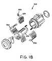
- FIG. 1is an exploded front, top and right side perspective view of the first embodiment of a master keying lock constructed in accordance with the present invention.
- FIG. 2is an enlarged front, top and right-side perspective view of the sleeve of the master keying lock illustrated in FIG. 1 .
- FIG. 3is an enlarged front elevational view of the tumblers illustrated in FIG. 1 .
- FIG. 4is a cross-sectioned side elevational view of the lock illustrated in FIG. 1 and showing the tumblers and sleeve in the “locked” or “key out” position.
- FIG. 5is a view of the lock illustrated in FIG. 4 and showing added detail.
- FIG. 6is a cross-sectioned side elevational view of the lock illustrated in FIG. 4 and showing the tumblers and sleeve in the “unlocked” or “key in” position with a standard key.
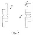
- FIG. 7is a drawing illustrating the profiles for the keys that would be used with the lock illustrated in FIG. 1 .
- FIG. 8is a cross-sectioned side elevational view and showing the detail of the sleeve and drive tumbler in the “key out” position.
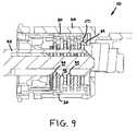
- FIG. 9is a view similar to FIG. 8 and showing the master key interaction with the drive tumbler.
- FIG. 10is a cross-sectioned and front elevational view of the lock shown in FIG. 9 following rotation of the master key.
- FIG. 11is an exploded front, top and right-side perspective view of the second embodiment of a master keying lock constructed in accordance with the present invention.
- FIG. 12is a top plan view of the unexploded lock system shown in FIG. 11 .
- FIG. 13is a cross-sectioned a side elevational view of the lock system illustrated in FIG. 12 and showing the shim and tumblers where the master key is extracted.
- FIG. 14is a cross-sectioned a side elevational view of the lock illustrated in FIG. 12 and showing initial insertion of the master key.
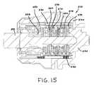
- FIG. 15is a cross-sectioned a side elevational view of the lock illustrated in FIG. 12 and showing full insertion of the master key.
- FIG. 16is a cross-sectioned a side elevational view of the lock illustrated in FIG. 12 and showing full insertion of the standard key.
- FIG. 17is a perspective view of the key profiles for the keys that would be used with the lock illustrated in FIG. 11 .
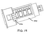
- FIG. 18is an exploded front, top and right-side perspective view of the third embodiment of a master keying lock constructed in accordance with the present invention.
- FIG. 19is a top plan view of the lock cylinder of the lock shown in FIG. 18 .
- FIG. 20is a perspective view of a pivot shim used in the lock illustrated in FIG. 18 .
- FIG. 1illustrates a perspective view of the first preferred embodiment of a master keying system, generally identified 10 , that is constructed in accordance with the present invention. It is to be understood that the instant invention is not limited to any particular application and may be incorporated into any number of lock assemblies for doors, devices, containers, motor vehicles, and the like, the application not being a limitation of the present invention.
- the system 10includes a case 20 and a sleeve 30 , the sleeve 30 being dimensioned to be slidably received within the case 20 .
- Means for axially moving the sleeve 30 within the case 20is also provided.
- the sleeve 30is spring-loaded and can move axially within the case 20 thereby changing positions depending on the specific key that is inserted into the lock cylinder 40 .
- Springs 2are disposed to either side of the sleeve 30 and are effectively captured and retained within grooves 32 formed within the sleeve 30 and complementary grooves 22 that are defined within the case 20 .
- a stop member 34is provided to one end of each of the sleeve grooves 32 which provides a surface against which a spring 2 can seat.
- a similar structure(not shown) is formed within the case 20 . Circumferential rotation of the sleeve 30 within the case 20 is prevented by engagement between axial ribs 38 of the sleeve 30 and complementary slots 26 within the case 20 . See also FIG. 2 .
- the system 10 of the first preferred embodimentalso comprises a lock cylinder 40 of the type that can be used to effect movement of a latch element (not shown) that is operatively connected to the lock cylinder 40 .
- the lock cylinder 40includes three different types of “wafers” or tumblers within the cylinder 40 .
- the tumblerscomprise a drive tumbler 50 , two master tumblers 60 and five locking/unlocking tumblers 70 . See also FIG. 3 .
- the number of master tumblers 60 and the numbers of locking/unlocking tumblers 70may vary without deviating from the scope of the present invention. There may actually be any number of master tumblers 60 and locking/unlocking tumblers 70 within the first preferred embodiment of the present invention.
- the locking/unlocking tumblers 70 and the master tumblers 60are spring-loaded (not shown) in the same direction.
- the drive tumbler 50is spring-loaded (also not shown) on the opposite side.
- the drive tumbler 50includes a protrusion 54 within the key window 52 , the purpose and function of which will be discussed later in this detailed description. Again, see FIG. 3 .
- the keyWith respect to the master tumbler 60 , the key, when inserted, is intended to ride on the bottom edge 64 of the key window 62 .
- FIG. 4it shows the position of the tumblers 50 , 60 , 70 and the sleeve 30 in the “locked” or “key out” position. As illustrated, it will be appreciated that the locking/unlocking tumblers 70 engage the sleeve 30 and do not allow rotation. The master tumblers 60 and the drive tumbler 50 do not engage the sleeve 30 . See FIG. 5 .
- FIG. 6it shows the “unlocked” position of the system 10 during normal key operation.
- the key 80has a profile 82 of key notches 84 defined within it.
- the locking/unlocking tumblers 70“drop” to the unlocked position within the body of the cylinder 40 .
- the master tumblers 60move to unknown positions between the key notches 84 . This allows them to rotate through slots 36 defined within the sleeve 30 .
- the key 80does not touch the drive tumbler 50 although the drive tumbler 50 is allowed to rotate through a slot 36 in the sleeve 30 as well.
- a master key 90 having an edge profile 92 as shown in FIG. 7is provided. Its profile 92 is compared to the standard key 80 as shown in the same FIG. 7 .
- the key way 42 in the cylinder 40is, however, modified to allow access to the drive tumbler 50 by means of the master key 90 , the master key 90 having a protrusion 96 defined within it. Note that insertion of the standard key 80 does not touch the drive tumbler 50 . The drive tumbler 50 is, however, dropped by insertion of the master key 90 .
- the lock cylinder 40will not rotate unless proper master key notches 94 are present. Further, the locking/unlocking tumblers 70 no longer engage the sleeve 30 and are allowed to rotate through the slots 36 defined within the sleeve 30 . See also FIG. 10 .
- the master keying arrangement in this first preferred embodiment of the present inventionis accomplished is by use of the axially-movable sleeve 30 .
- the sleeve 30shifts the locking surface engaging either the locking/unlocking tumblers 70 or the master tumblers 60 .
- Sleeve 30 shiftscan only be accomplished by use of the master key 90 .
- Standard keys 80do not contact the drive tumbler 50 which shifts position of the sleeve 30 when inserted as described above.
- the correct key profile 82 and key notching 84must be present to rotate the lock cylinder 40 within the sleeve 30 .
- the correct key notching for the master tumblers 60 as well as the drive surface for the drive tumbler 50must be present to rotate the cylinder 40 . Again, see FIG. 10 .
- FIG. 11it illustrates a perspective view of a second preferred embodiment of a master keying system, generally identified 210 , that is constructed in accordance with the present invention.
- the system 210similarly includes a case 220 and a sleeve 230 , the sleeve 230 also being dimensioned to be slidably received within the case 220 and being formed of two half members, although such is not a limitation of the present invention.
- Means for axially moving the sleeve 230 within the case 220is also provided. Specifically, the sleeve 230 is spring-loaded and can move axially within the case 220 thereby changing positions depending on the specific key that is inserted into the lock cylinder 240 .
- Springs 202are disposed to either side of the sleeve 230 and are captured within grooves 232 formed within the sleeve 230 and complementary grooves 222 that are defined within the case 220 .
- a stop member 234is provided to one end of each of the sleeve grooves 232 which provides a surface against which the spring 202 can seat.
- a similar structure(not shown) is formed within the case 220 . Circumferential rotation of the sleeve 230 within the case 220 is likewise prevented by structure that is similar to that of the first preferred embodiment discussed above.
- system 210 of the second preferred embodiment of the present inventionachieves its functionality by adjusting tumbler locking surfaces based on whether a “standard” key or a “master” key is used with the sleeve 230 .
- the system 210 of the second preferred embodimentalso comprises a cap 204 and a keyway shutter assembly 206 , both of which are preferred but not essential to the present invention. More importantly, the system further comprises a lock cylinder 240 and a shim 250 .
- the lock cylinder 240includes two different types of tumblers within it. Specifically, the tumblers comprise a plurality of “master” tumblers 260 and a plurality of “standard” locking/unlocking tumblers 270 , the precise number of tumblers 260 , 270 not being a limitation of the present invention. In point of fact, one added benefit of using the tumblers 260 , 270 of the second preferred embodiment is that each is simply an inverted version of the other, which is a manufacturing expediency. As before, the master tumblers 260 and the standard locking/unlocking tumblers 270 are spring-loaded (not shown) but are biased in opposite directions.
- FIG. 12it shows the position of the shim 250 and tumblers 260 , 270 and the sleeve 230 in the “locked” or “key out” position, where the “master” key is extracted.
- the sleeve 230creates a locking surface with the standard locking/unlocking tumblers 270 . See FIG. 13 .
- this retracts the first master tumbler 260 aallowing both the shim 250 and the sleeve 230 to freely travel axially relative to the cylinder 240 when a master key member or “flat” 298 contacts the shim 250 .
- the standard key 280does not have this member or flat 298 . See FIGS. 16 and 17 .
- a third preferred embodimentis also contemplated within the scope of the present invention.
- this third system 310an alternative structure to the shim 250 of the second system 210 is presented.
- the shim 250is replaced by a “pivot” shim 350 , the pivot shim 350 having a post 352 that is rotatable within an aperture 342 defined within the lock cylinder 340 .
- the shim 350functions in the same way to move the sleeve 330 in an axial direction when a master key 290 is used with the system 310 .
- the master keying arrangement in the second and third embodiments of the present inventionis likewise accomplished by use of an axially-movable sleeve 230 , 330 .
- the sleeves 230 , 330shift the locking surface engaging either the locking/unlocking tumblers 270 , 370 or the master tumblers 260 , 360 .
- Sleeve 230 , 330 shiftscan only be accomplished by use of the master key 290 .
- the standard key 280does not contact the shims 250 , 350 which shift position of the sleeves 230 , 330 when inserted as described above.
- the correct key notching 284In the standard operation, the correct key notching 284 must be present to rotate the lock cylinders 240 , 340 within the sleeves 230 , 330 , respectively.
- the correct key notching for the master tumblers 260 , 360 as well as the surface 298 of the master key 290must be present to contact the shims 250 , 350 thus allowing rotation of the cylinders 240 , 340 .
- a new and useful master keying lock, system and methodthat provides for a master keying system which allows the lock to be unlocked with the original key provided for the lock as well as with a master key. It further provides use of existing tumblers and key of the lock and also allows for “backwards compatibility” of those elements. All of this is accomplished by use of a master keying feature that uses a moveable sleeve that shifts the locking surface within the lock casing relative to wafer tumblers that are used within the lock.
Landscapes
- Physics & Mathematics (AREA)
- Electromagnetism (AREA)
- Lock And Its Accessories (AREA)
Abstract
Description
Claims (8)
Priority Applications (1)
| Application Number | Priority Date | Filing Date | Title |
|---|---|---|---|
| US12/708,126US8276416B2 (en) | 2009-02-18 | 2010-02-18 | Master key lock, system and method |
Applications Claiming Priority (2)
| Application Number | Priority Date | Filing Date | Title |
|---|---|---|---|
| US15351309P | 2009-02-18 | 2009-02-18 | |
| US12/708,126US8276416B2 (en) | 2009-02-18 | 2010-02-18 | Master key lock, system and method |
Publications (2)
| Publication Number | Publication Date |
|---|---|
| US20100206025A1 US20100206025A1 (en) | 2010-08-19 |
| US8276416B2true US8276416B2 (en) | 2012-10-02 |
Family
ID=42558709
Family Applications (1)
| Application Number | Title | Priority Date | Filing Date |
|---|---|---|---|
| US12/708,126Active2030-08-08US8276416B2 (en) | 2009-02-18 | 2010-02-18 | Master key lock, system and method |
Country Status (1)
| Country | Link |
|---|---|
| US (1) | US8276416B2 (en) |
Cited By (2)
| Publication number | Priority date | Publication date | Assignee | Title |
|---|---|---|---|---|
| US20080178647A1 (en)* | 2005-02-11 | 2008-07-31 | Valeo Securite Habitacle | Rotary Cylinder Lock Which Can Be Actuated with a Multi-Groove Key |
| US9816290B2 (en)* | 2015-05-29 | 2017-11-14 | Kabushiki Kaisha Tokai Rika Denki Seisakusho | Key cylinder device |
Families Citing this family (5)
| Publication number | Priority date | Publication date | Assignee | Title |
|---|---|---|---|---|
| US9657499B2 (en)* | 2011-10-10 | 2017-05-23 | Spectrum Brands, Inc. | Method and apparatus for a rekeyable master key lock |
| US9512642B2 (en)* | 2014-03-07 | 2016-12-06 | Keyless.Co, Llc | Reprogrammable cylinder lock |
| USD804283S1 (en) | 2016-12-21 | 2017-12-05 | Jeff Jasper | Lock cylinder anti-crush sleeve for hollow door |
| CN109930907B (en)* | 2019-04-02 | 2024-01-23 | 珠海优特电力科技股份有限公司 | Lock cylinder system, key system and lockset system |
| US20250188769A1 (en)* | 2023-12-12 | 2025-06-12 | Assa Abloy Americas Residential Inc. | Rekeyable lock cylinder with double sided keyway |
Citations (39)
| Publication number | Priority date | Publication date | Assignee | Title |
|---|---|---|---|---|
| US1456584A (en)* | 1920-04-22 | 1923-05-29 | Dillwyn M Bell | Key lock |
| US1990794A (en)* | 1933-01-31 | 1935-02-12 | William J Mccormac | Lock |
| US2117515A (en)* | 1937-03-24 | 1938-05-17 | Sinner Emil | Lock |
| US2683978A (en)* | 1952-03-31 | 1954-07-20 | Briggs & Stratton Corp | Door latch operating mechanism with weather seal |
| US3194034A (en)* | 1962-11-05 | 1965-07-13 | Leiser Milton | Cylinder lock |
| US3499209A (en)* | 1967-11-24 | 1970-03-10 | Rhodes Inc M H | Lock assembly |
| US3555859A (en)* | 1968-11-12 | 1971-01-19 | Nathan L Berkowitz | Cylinder lock |
| US4280349A (en)* | 1978-05-20 | 1981-07-28 | Daimler-Benz Aktiengesellschaft | Rotary cylinder lock, especially for automotive vehicles |
| US4351171A (en)* | 1980-07-01 | 1982-09-28 | China National Light Industrial Products Import Export Corporation, Shantung Branch | Sequential locking two key lock |
| US4682484A (en)* | 1986-04-15 | 1987-07-28 | Yeh Ching Hsuan | Tumbler plate cylinder lock |
| US4759204A (en)* | 1985-11-14 | 1988-07-26 | Neiman S.A. | Lock mechanism |
| US4956983A (en)* | 1988-09-22 | 1990-09-18 | Kabushiki Kaisha Tokai Rika Denki Seisakusho | Locking apparatus with a key |
| US5070716A (en)* | 1989-02-23 | 1991-12-10 | Rover Group Limited | Locking mechanism |
| US5263348A (en)* | 1991-07-06 | 1993-11-23 | Hulsbeck & Furst Gmbh & Co. Kg | Cylinder lock |
| US5265453A (en)* | 1990-11-30 | 1993-11-30 | Alpha Corporation | Cylinder lock |
| USRE35518E (en)* | 1991-04-10 | 1997-05-27 | Medeco Security Locks, Inc. | Restricted key system |
| US5640864A (en)* | 1993-12-27 | 1997-06-24 | Alpha Corporation | Cylinder lock resistible against breaking |
| US5722275A (en)* | 1996-05-09 | 1998-03-03 | Strattec Security Corporation | Pushbutton console latch |
| US5732580A (en)* | 1996-05-10 | 1998-03-31 | Valeo Securite Habitacle | Axially disengageable lock for a motor vehicle locking system |
| US6463774B2 (en)* | 2000-05-17 | 2002-10-15 | Southco, Inc. | Push lock |
| US6516643B1 (en)* | 2000-06-09 | 2003-02-11 | Michael Cohnitz Olshausen | Pop-up, precision lock-cylinder that reveals at once, with visual and tactile cues, who else with a key has sought or gained entry |
| US6523382B1 (en)* | 1998-09-08 | 2003-02-25 | Strattec Security Corporation | Free wheeling lock assembly |
| US20030172695A1 (en)* | 2000-09-21 | 2003-09-18 | Gerd Buschmann | Device comprising a momentary contact switch for actuating a lock on a door or hinged lid, in particular, for a vehicle |
| US6826936B1 (en)* | 2003-12-31 | 2004-12-07 | Hsieh Ming-Er | Burglarproof lock core with plate tumblers |
| US6886381B2 (en)* | 2000-06-27 | 2005-05-03 | Huf Hülsbeck & Fürst Gmbh & Co. Kg | Actuating device for a lock, especially in a motor vehicle |
| US6889534B2 (en)* | 2002-05-23 | 2005-05-10 | Thomas M. Koluch | Controlled access lock |
| US6920770B2 (en)* | 2003-06-03 | 2005-07-26 | Alan E. Lurie | Plunger lock assembly with removable core |
| US6964184B1 (en)* | 2001-04-19 | 2005-11-15 | Tuffy Security Products, Inc. | Shielded pushbutton lock |
| US6968717B2 (en)* | 2000-03-09 | 2005-11-29 | Alpha Corporation | Cylinder lock |
| US20060201216A1 (en)* | 2003-09-30 | 2006-09-14 | Gil Benito S | Master-keyed cylinder comprising tumblers and corresponding master key |
| US7205492B1 (en)* | 2005-03-14 | 2007-04-17 | The Eastern Company | Push button actuator |
| US7340929B1 (en)* | 2005-03-21 | 2008-03-11 | Efthemois Christopoulos | Axially rotative rekeyable lock |
| US7377142B2 (en)* | 2004-03-15 | 2008-05-27 | Zdravko Rajacic | Cylinder lock with coded key for blocking the shaft of the steering wheel and protection of the motor vehicle from theft |
| US7406847B2 (en)* | 2004-07-02 | 2008-08-05 | Honda Lock Mfg. Co., Ltd. | Cylinder lock |
| US7716960B2 (en)* | 2006-07-06 | 2010-05-18 | Kabushiki Kaisha Tokai-Rika-Denki-Seisakusho | Lock device |
| US7895868B2 (en)* | 2007-07-30 | 2011-03-01 | Kabushiki Kaisha Tokai-Rika-Denki-Seisakusho | Cylinder lock and unlocking device comprising thereof |
| US7930917B2 (en)* | 2007-03-30 | 2011-04-26 | Kabushiki Kaisha Tokai-Rika-Denki-Seisakusho | Lock device |
| US7958759B2 (en)* | 2008-07-10 | 2011-06-14 | Janaka Limited Partnership | Key-removable lock core |
| US7963133B2 (en)* | 2007-10-25 | 2011-06-21 | Kabushiki Kaisha Tokai Rika Denki Seisakusho | Cylinder lock and unlocking device comprising thereof |
- 2010
- 2010-02-18USUS12/708,126patent/US8276416B2/enactiveActive
Patent Citations (39)
| Publication number | Priority date | Publication date | Assignee | Title |
|---|---|---|---|---|
| US1456584A (en)* | 1920-04-22 | 1923-05-29 | Dillwyn M Bell | Key lock |
| US1990794A (en)* | 1933-01-31 | 1935-02-12 | William J Mccormac | Lock |
| US2117515A (en)* | 1937-03-24 | 1938-05-17 | Sinner Emil | Lock |
| US2683978A (en)* | 1952-03-31 | 1954-07-20 | Briggs & Stratton Corp | Door latch operating mechanism with weather seal |
| US3194034A (en)* | 1962-11-05 | 1965-07-13 | Leiser Milton | Cylinder lock |
| US3499209A (en)* | 1967-11-24 | 1970-03-10 | Rhodes Inc M H | Lock assembly |
| US3555859A (en)* | 1968-11-12 | 1971-01-19 | Nathan L Berkowitz | Cylinder lock |
| US4280349A (en)* | 1978-05-20 | 1981-07-28 | Daimler-Benz Aktiengesellschaft | Rotary cylinder lock, especially for automotive vehicles |
| US4351171A (en)* | 1980-07-01 | 1982-09-28 | China National Light Industrial Products Import Export Corporation, Shantung Branch | Sequential locking two key lock |
| US4759204A (en)* | 1985-11-14 | 1988-07-26 | Neiman S.A. | Lock mechanism |
| US4682484A (en)* | 1986-04-15 | 1987-07-28 | Yeh Ching Hsuan | Tumbler plate cylinder lock |
| US4956983A (en)* | 1988-09-22 | 1990-09-18 | Kabushiki Kaisha Tokai Rika Denki Seisakusho | Locking apparatus with a key |
| US5070716A (en)* | 1989-02-23 | 1991-12-10 | Rover Group Limited | Locking mechanism |
| US5265453A (en)* | 1990-11-30 | 1993-11-30 | Alpha Corporation | Cylinder lock |
| USRE35518E (en)* | 1991-04-10 | 1997-05-27 | Medeco Security Locks, Inc. | Restricted key system |
| US5263348A (en)* | 1991-07-06 | 1993-11-23 | Hulsbeck & Furst Gmbh & Co. Kg | Cylinder lock |
| US5640864A (en)* | 1993-12-27 | 1997-06-24 | Alpha Corporation | Cylinder lock resistible against breaking |
| US5722275A (en)* | 1996-05-09 | 1998-03-03 | Strattec Security Corporation | Pushbutton console latch |
| US5732580A (en)* | 1996-05-10 | 1998-03-31 | Valeo Securite Habitacle | Axially disengageable lock for a motor vehicle locking system |
| US6523382B1 (en)* | 1998-09-08 | 2003-02-25 | Strattec Security Corporation | Free wheeling lock assembly |
| US6968717B2 (en)* | 2000-03-09 | 2005-11-29 | Alpha Corporation | Cylinder lock |
| US6463774B2 (en)* | 2000-05-17 | 2002-10-15 | Southco, Inc. | Push lock |
| US6516643B1 (en)* | 2000-06-09 | 2003-02-11 | Michael Cohnitz Olshausen | Pop-up, precision lock-cylinder that reveals at once, with visual and tactile cues, who else with a key has sought or gained entry |
| US6886381B2 (en)* | 2000-06-27 | 2005-05-03 | Huf Hülsbeck & Fürst Gmbh & Co. Kg | Actuating device for a lock, especially in a motor vehicle |
| US20030172695A1 (en)* | 2000-09-21 | 2003-09-18 | Gerd Buschmann | Device comprising a momentary contact switch for actuating a lock on a door or hinged lid, in particular, for a vehicle |
| US6964184B1 (en)* | 2001-04-19 | 2005-11-15 | Tuffy Security Products, Inc. | Shielded pushbutton lock |
| US6889534B2 (en)* | 2002-05-23 | 2005-05-10 | Thomas M. Koluch | Controlled access lock |
| US6920770B2 (en)* | 2003-06-03 | 2005-07-26 | Alan E. Lurie | Plunger lock assembly with removable core |
| US20060201216A1 (en)* | 2003-09-30 | 2006-09-14 | Gil Benito S | Master-keyed cylinder comprising tumblers and corresponding master key |
| US6826936B1 (en)* | 2003-12-31 | 2004-12-07 | Hsieh Ming-Er | Burglarproof lock core with plate tumblers |
| US7377142B2 (en)* | 2004-03-15 | 2008-05-27 | Zdravko Rajacic | Cylinder lock with coded key for blocking the shaft of the steering wheel and protection of the motor vehicle from theft |
| US7406847B2 (en)* | 2004-07-02 | 2008-08-05 | Honda Lock Mfg. Co., Ltd. | Cylinder lock |
| US7205492B1 (en)* | 2005-03-14 | 2007-04-17 | The Eastern Company | Push button actuator |
| US7340929B1 (en)* | 2005-03-21 | 2008-03-11 | Efthemois Christopoulos | Axially rotative rekeyable lock |
| US7716960B2 (en)* | 2006-07-06 | 2010-05-18 | Kabushiki Kaisha Tokai-Rika-Denki-Seisakusho | Lock device |
| US7930917B2 (en)* | 2007-03-30 | 2011-04-26 | Kabushiki Kaisha Tokai-Rika-Denki-Seisakusho | Lock device |
| US7895868B2 (en)* | 2007-07-30 | 2011-03-01 | Kabushiki Kaisha Tokai-Rika-Denki-Seisakusho | Cylinder lock and unlocking device comprising thereof |
| US7963133B2 (en)* | 2007-10-25 | 2011-06-21 | Kabushiki Kaisha Tokai Rika Denki Seisakusho | Cylinder lock and unlocking device comprising thereof |
| US7958759B2 (en)* | 2008-07-10 | 2011-06-14 | Janaka Limited Partnership | Key-removable lock core |
Cited By (2)
| Publication number | Priority date | Publication date | Assignee | Title |
|---|---|---|---|---|
| US20080178647A1 (en)* | 2005-02-11 | 2008-07-31 | Valeo Securite Habitacle | Rotary Cylinder Lock Which Can Be Actuated with a Multi-Groove Key |
| US9816290B2 (en)* | 2015-05-29 | 2017-11-14 | Kabushiki Kaisha Tokai Rika Denki Seisakusho | Key cylinder device |
Also Published As
| Publication number | Publication date |
|---|---|
| US20100206025A1 (en) | 2010-08-19 |
Similar Documents
| Publication | Publication Date | Title |
|---|---|---|
| US8276416B2 (en) | Master key lock, system and method | |
| AU2021269400B2 (en) | Rekeyable lock cylinder with enhanced torque resistance | |
| US7900491B2 (en) | Rekeyable lock assembly and method of operation | |
| US3418833A (en) | Tamperproof cylinder lock | |
| US11702862B2 (en) | Modular lock plug | |
| US7963135B1 (en) | System for obstructing movement of lock pins | |
| US7047778B2 (en) | Vehicular lock apparatus and method | |
| US12024921B2 (en) | Tool-less rekeyable lock cylinder | |
| GB2491585A (en) | Cylinder lock with clutch | |
| AU2013204413A1 (en) | Lock system | |
| JP2003293626A (en) | Cylinder used for cylinder lock, and cylinder lock provided with the same |
Legal Events
| Date | Code | Title | Description |
|---|---|---|---|
| AS | Assignment | Owner name:VSI, LLC, WISCONSIN Free format text:ASSIGNMENT OF ASSIGNORS INTEREST;ASSIGNORS:BOESEL, LUCAS;MILLER, JOSHUA J.;REEL/FRAME:024224/0223 Effective date:20100409 | |
| STCF | Information on status: patent grant | Free format text:PATENTED CASE | |
| FPAY | Fee payment | Year of fee payment:4 | |
| MAFP | Maintenance fee payment | Free format text:PAYMENT OF MAINTENANCE FEE, 8TH YR, SMALL ENTITY (ORIGINAL EVENT CODE: M2552); ENTITY STATUS OF PATENT OWNER: SMALL ENTITY Year of fee payment:8 | |
| AS | Assignment | Owner name:FIRST BANK, MISSOURI Free format text:SECURITY INTEREST;ASSIGNOR:VEHICLE SECURITY INNOVATORS, LLC;REEL/FRAME:062677/0047 Effective date:20230201 Owner name:VEHICLE SECURITY INNOVATORS, LLC, WISCONSIN Free format text:ASSIGNMENT OF ASSIGNORS INTEREST;ASSIGNORS:VEHICLE SECURITY INNOVATORS, INC.;VSI, LLC;POP & LOCK LLC;AND OTHERS;REEL/FRAME:062676/0843 Effective date:20230201 | |
| FEPP | Fee payment procedure | Free format text:MAINTENANCE FEE REMINDER MAILED (ORIGINAL EVENT CODE: REM.); ENTITY STATUS OF PATENT OWNER: SMALL ENTITY | |
| FEPP | Fee payment procedure | Free format text:11.5 YR SURCHARGE- LATE PMT W/IN 6 MO, SMALL ENTITY (ORIGINAL EVENT CODE: M2556); ENTITY STATUS OF PATENT OWNER: SMALL ENTITY | |
| MAFP | Maintenance fee payment | Free format text:PAYMENT OF MAINTENANCE FEE, 12TH YR, SMALL ENTITY (ORIGINAL EVENT CODE: M2553); ENTITY STATUS OF PATENT OWNER: SMALL ENTITY Year of fee payment:12 |