US8275471B2 - Sensor interface for wireless control - Google Patents
Sensor interface for wireless controlDownload PDFInfo
- Publication number
- US8275471B2 US8275471B2US12/912,717US91271710AUS8275471B2US 8275471 B2US8275471 B2US 8275471B2US 91271710 AUS91271710 AUS 91271710AUS 8275471 B2US8275471 B2US 8275471B2
- Authority
- US
- United States
- Prior art keywords
- sensor
- information
- environmental condition
- electrical load
- detected
- Prior art date
- Legal status (The legal status is an assumption and is not a legal conclusion. Google has not performed a legal analysis and makes no representation as to the accuracy of the status listed.)
- Active
Links
- 238000004891communicationMethods0.000claimsabstractdescription50
- 230000007613environmental effectEffects0.000claimsabstractdescription44
- 238000000034methodMethods0.000claimsabstractdescription22
- 238000001514detection methodMethods0.000claimsdescription7
- 238000012544monitoring processMethods0.000claimsdescription4
- 230000003213activating effectEffects0.000claimsdescription3
- 230000033001locomotionEffects0.000description21
- 238000003860storageMethods0.000description16
- 230000004044responseEffects0.000description15
- 238000009434installationMethods0.000description8
- 238000010586diagramMethods0.000description6
- 230000003287optical effectEffects0.000description5
- 230000002093peripheral effectEffects0.000description4
- 230000005540biological transmissionEffects0.000description3
- 239000003990capacitorSubstances0.000description3
- 230000008859changeEffects0.000description3
- 230000005611electricityEffects0.000description3
- 230000001276controlling effectEffects0.000description2
- 230000002596correlated effectEffects0.000description2
- 230000000694effectsEffects0.000description2
- 238000005516engineering processMethods0.000description2
- 230000008569processEffects0.000description2
- 238000012545processingMethods0.000description2
- 238000009420retrofittingMethods0.000description2
- 238000005096rolling processMethods0.000description2
- WHXSMMKQMYFTQS-UHFFFAOYSA-NLithiumChemical compound[Li]WHXSMMKQMYFTQS-UHFFFAOYSA-N0.000description1
- 230000004913activationEffects0.000description1
- 238000004378air conditioningMethods0.000description1
- 230000008901benefitEffects0.000description1
- 238000006243chemical reactionMethods0.000description1
- 238000010276constructionMethods0.000description1
- 230000000875corresponding effectEffects0.000description1
- 230000008878couplingEffects0.000description1
- 238000010168coupling processMethods0.000description1
- 238000005859coupling reactionMethods0.000description1
- 238000009795derivationMethods0.000description1
- 230000009977dual effectEffects0.000description1
- 238000005265energy consumptionMethods0.000description1
- 238000003306harvestingMethods0.000description1
- 238000010438heat treatmentMethods0.000description1
- 230000000977initiatory effectEffects0.000description1
- 230000010354integrationEffects0.000description1
- 238000003973irrigationMethods0.000description1
- 230000002262irrigationEffects0.000description1
- 239000004973liquid crystal related substanceSubstances0.000description1
- 229910052744lithiumInorganic materials0.000description1
- 238000012423maintenanceMethods0.000description1
- 238000012986modificationMethods0.000description1
- 230000004048modificationEffects0.000description1
- 238000011022operating instructionMethods0.000description1
- 230000001105regulatory effectEffects0.000description1
- 230000035945sensitivityEffects0.000description1
- 230000007704transitionEffects0.000description1
- 230000035899viabilityEffects0.000description1
- 239000002699waste materialSubstances0.000description1
Images


Classifications
- G—PHYSICS
- G01—MEASURING; TESTING
- G01V—GEOPHYSICS; GRAVITATIONAL MEASUREMENTS; DETECTING MASSES OR OBJECTS; TAGS
- G01V8/00—Prospecting or detecting by optical means
- G01V8/10—Detecting, e.g. by using light barriers
- G01V8/20—Detecting, e.g. by using light barriers using multiple transmitters or receivers
- H—ELECTRICITY
- H05—ELECTRIC TECHNIQUES NOT OTHERWISE PROVIDED FOR
- H05B—ELECTRIC HEATING; ELECTRIC LIGHT SOURCES NOT OTHERWISE PROVIDED FOR; CIRCUIT ARRANGEMENTS FOR ELECTRIC LIGHT SOURCES, IN GENERAL
- H05B47/00—Circuit arrangements for operating light sources in general, i.e. where the type of light source is not relevant
- H05B47/10—Controlling the light source
- H05B47/105—Controlling the light source in response to determined parameters
- H05B47/11—Controlling the light source in response to determined parameters by determining the brightness or colour temperature of ambient light
- G—PHYSICS
- G01—MEASURING; TESTING
- G01N—INVESTIGATING OR ANALYSING MATERIALS BY DETERMINING THEIR CHEMICAL OR PHYSICAL PROPERTIES
- G01N21/00—Investigating or analysing materials by the use of optical means, i.e. using sub-millimetre waves, infrared, visible or ultraviolet light
- G01N21/17—Systems in which incident light is modified in accordance with the properties of the material investigated
- G01N21/25—Colour; Spectral properties, i.e. comparison of effect of material on the light at two or more different wavelengths or wavelength bands
- G01N21/255—Details, e.g. use of specially adapted sources, lighting or optical systems
- G—PHYSICS
- G01—MEASURING; TESTING
- G01N—INVESTIGATING OR ANALYSING MATERIALS BY DETERMINING THEIR CHEMICAL OR PHYSICAL PROPERTIES
- G01N21/00—Investigating or analysing materials by the use of optical means, i.e. using sub-millimetre waves, infrared, visible or ultraviolet light
- G01N21/17—Systems in which incident light is modified in accordance with the properties of the material investigated
- G01N21/25—Colour; Spectral properties, i.e. comparison of effect of material on the light at two or more different wavelengths or wavelength bands
- G01N21/27—Colour; Spectral properties, i.e. comparison of effect of material on the light at two or more different wavelengths or wavelength bands using photo-electric detection ; circuits for computing concentration
- G—PHYSICS
- G05—CONTROLLING; REGULATING
- G05B—CONTROL OR REGULATING SYSTEMS IN GENERAL; FUNCTIONAL ELEMENTS OF SUCH SYSTEMS; MONITORING OR TESTING ARRANGEMENTS FOR SUCH SYSTEMS OR ELEMENTS
- G05B15/00—Systems controlled by a computer
- G05B15/02—Systems controlled by a computer electric
- H—ELECTRICITY
- H05—ELECTRIC TECHNIQUES NOT OTHERWISE PROVIDED FOR
- H05B—ELECTRIC HEATING; ELECTRIC LIGHT SOURCES NOT OTHERWISE PROVIDED FOR; CIRCUIT ARRANGEMENTS FOR ELECTRIC LIGHT SOURCES, IN GENERAL
- H05B47/00—Circuit arrangements for operating light sources in general, i.e. where the type of light source is not relevant
- H05B47/10—Controlling the light source
- H05B47/105—Controlling the light source in response to determined parameters
- H05B47/115—Controlling the light source in response to determined parameters by determining the presence or movement of objects or living beings
- G—PHYSICS
- G01—MEASURING; TESTING
- G01N—INVESTIGATING OR ANALYSING MATERIALS BY DETERMINING THEIR CHEMICAL OR PHYSICAL PROPERTIES
- G01N21/00—Investigating or analysing materials by the use of optical means, i.e. using sub-millimetre waves, infrared, visible or ultraviolet light
- G01N21/17—Systems in which incident light is modified in accordance with the properties of the material investigated
- G01N2021/1793—Remote sensing
- Y—GENERAL TAGGING OF NEW TECHNOLOGICAL DEVELOPMENTS; GENERAL TAGGING OF CROSS-SECTIONAL TECHNOLOGIES SPANNING OVER SEVERAL SECTIONS OF THE IPC; TECHNICAL SUBJECTS COVERED BY FORMER USPC CROSS-REFERENCE ART COLLECTIONS [XRACs] AND DIGESTS
- Y02—TECHNOLOGIES OR APPLICATIONS FOR MITIGATION OR ADAPTATION AGAINST CLIMATE CHANGE
- Y02B—CLIMATE CHANGE MITIGATION TECHNOLOGIES RELATED TO BUILDINGS, e.g. HOUSING, HOUSE APPLIANCES OR RELATED END-USER APPLICATIONS
- Y02B20/00—Energy efficient lighting technologies, e.g. halogen lamps or gas discharge lamps
- Y02B20/40—Control techniques providing energy savings, e.g. smart controller or presence detection
Definitions
- the present inventiongenerally involves wireless control. More specifically, the present invention relates to a sensor interface for enabling wireless communication with a wired sensor.
- a sensorfor detecting certain environmental conditions and initiating a adjustment of an electrical load device (i.e., electricity-consuming device) in response to the detected condition(s).
- an electrical load devicei.e., electricity-consuming device
- some building installationse.g., offices
- An occupancy sensor wired to a lighting fixturemay detect movement or lack of movement in a particular room and cause the lighting fixture to turn on or off in response.
- Such sensormay initiate such response by communicating with an actuator or switch of the electrical load device.
- a sensormay have to be rewired when electrical load devices are added, removed, or relocated and when user preferences change. Such situations may require rewiring and reconfiguration of sensor settings to reflect the new arrangement and requirements thereof.
- wireless control solutionsmay allow for increased flexibility, implementing wireless solutions may include installing new wireless sensors, which may be costly for some installations.
- Embodiments of the present inventionprovide systems and methods for enabling wireless communication with a wired sensor. Power is supplied continuously to an electrical load device under control of a wireless controller. A wired sensor detects an environmental condition. The detected information may be received at a wireless interface communicatively coupled to the wired sensor. The wireless interface transmits the detected information to the wireless controller, which may then control operation of the electrical load device based on the detected information.
- FIG. 1For enabling wireless communication with wired sensors.
- Such systemsmay include a power source for supplying continuous power to an electrical load device that operates under control of a wireless controller and a sensor interface communicatively coupled to the wired sensor.
- a sensor interfacemay receive information regarding an environmental condition detected by the wired sensor and wirelessly transmit the information to the wireless controller.
- the wireless controllermay then control operation of the electrical load device based on the information wirelessly transmitted from the sensor interface.
- Embodiments of the present inventionmay further include methods for enabling wireless communication with a wired sensor. Such methods may include monitoring a wired sensor for generation of a signal indicating detection of an environmental condition, receiving a signal from the wired sensor at a sensor interface, regarding the environmental condition detected by the wired sensor, and wirelessly transmitting the information regarding the environmental condition from the sensor interface to a wireless controller. The wireless controller may then control operation of an electrical load device based on the information wirelessly transmitted from the sensor interface.
- FIG. 1may depict apparatuses for enabling wireless communication with a wired sensor and computer-readable storage media for performing methods for enabling wireless communication with a wired sensor.
- FIG. 1is a network environment in which may be implemented an exemplary system for enabling wireless communication with a wired sensor.
- FIG. 2is a diagram of a sensor system as known in the prior art.
- FIG. 3is a diagram of a system for enabling wireless communication with a wired sensor according to an exemplary embodiment of the present invention.
- FIG. 4is a block diagram of the sensor interface of FIG. 3 .
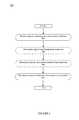
- FIG. 5is a flowchart illustrating an exemplary method for enabling wireless communication with a wired sensor.
- FIG. 6illustrates an exemplary computing system that may be used to implement an embodiment of the present invention.
- the present inventionprovides systems and methods for enabling wireless communication with a wired sensor. These systems and methods may be used to retrofit building installations by adapting pre-existing, wired sensors for wireless communication with wireless control systems.
- a sensor interfacemay be communicatively coupled with a sensor that provides information about a detected environmental condition.
- the sensor interfacemay wirelessly transmit information received from the sensor to a controller that may control an electrical load device based on the wirelessly transmitted information. Controlling an electrical load device, for example, may allow a building owner or facility manager to adapt to changing conditions and optimize operation of electrical load devices (e.g., lighting, room temperature), thereby reducing waste and energy costs.
- FIG. 1is a network environment 100 in which may be implemented an exemplary system for enabling wireless communication with a wired sensor.
- the network environment 100 of FIG. 1includes communications network 105 and 110 , firewall 115 , gateway 120 , database 125 , administrator station 130 , sensor interface 135 , wired sensor 140 , controller 145 , and electrical load device 150 .
- communications network 105 and 110includes communications network 105 and 110 , firewall 115 , gateway 120 , database 125 , administrator station 130 , sensor interface 135 , wired sensor 140 , controller 145 , and electrical load device 150 .
- FIG. 1is a network environment 100 in which may be implemented an exemplary system for enabling wireless communication with a wired sensor.
- the network environment 100 of FIG. 1includes communications network 105 and 110 , firewall 115 , gateway 120 , database 125 , administrator station 130 , sensor interface 135 , wired sensor 140 , controller 145 , and electrical load device 150 .
- FIG. 1is a
- Communication networks 105 and 110may include any of the various wireless communication networks that are known in the art, such as the Internet, Wide Area Network (WAN), Local Area Network (LAN), intranet, extranet, private network, or other network. As illustrated in FIG. 1 , communication network 105 may be a WAN that may be communicatively coupled to a LAN. Communication networks 105 and 110 allow for communication between the various parties in network environment 100 . In one embodiment, communication networks 105 and 110 may include a multi-hop, wireless mesh network.
- Network environment 100also referred to as wireless control system 100 , may include a firewall 115 and wireless gateway 120 as are known in the art, for ensuring secure data transmission and network.
- Database 125may be any database known in the art for storing and managing data concerning wireless control system 100 .
- Database 125may be housed separately or in association with administrator station 130 , sensor interface 135 , or controller 145 .
- Database 125may store, among other things, data or information received from sensor 140 .
- Database 125may also include other historical and operational data concerning device status, occupancy information, operating schedules, lighting levels, lighting parameters, other conditions and parameters, operating instructions, automated responses to signals from certain parties (e.g., demand response), preferences, energy usage, equipment failures, etc.
- Such data as stored in database 125may be factored into control decisions by controller 145 with respect to directing operation of electrical load device 150 .
- Administrator station 130is inclusive of a general purpose computing device such as that illustrated in FIG. 6 , described in detail below. Administrator station 130 may be implemented as a computing device such as a workstation, server, desktop computer, laptop computer, mobile device, or other computing device. Administrator station 130 may be used to receive and manage administrator settings regarding schedules, monitoring parameters, and/or control over the various components of the network environment 100 . For example, instead of manually programming various thresholds for each sensor 140 , such preferred operational settings may take multiple factors into consideration (e.g., amount of detected motion correlated to time delay, amount of detected daylight correlated to hours of operation) may be inputted at administrator station 130 and implemented via sensor interface 135 and/or controller 145 .
- factors into consideratione.g., amount of detected motion correlated to time delay, amount of detected daylight correlated to hours of operation
- Administrator station 130may also be used to control one or more electrical load devices 150 via controller 145 .
- a facilities manager or other usermay use administrator station 130 to manually control or input relevant parameters that may be factored into control decisions in wireless control system 100 .
- the facilities manager or other usermay use administrator station 130 to set preferences about operation of a particular electrical load device 150 under specified conditions.
- administrator station 130may provide a schedule of specific dates and/or times when a particular electric load device 150 should be on or off or dimmed.
- Administrator station 130may also perform other activities associated with wireless control system 100 , including monitoring or tracking energy usage, predicting electrical load device failures (e.g., failure of a lamp or ballast), managing demand response events, or responding to maintenance requirements.
- Sensor 140may be any wired sensor known in the art for detecting an environmental condition including but not limited to movement, light, temperature, or sound.
- Sensor 140may be, for example, a motion detection sensor, occupancy sensor, optical sensor (e.g., infrared, laser), light sensor, image sensor, photo sensor, sound sensor, etc.
- sensor 140is a low voltage occupancy sensor (e.g., ultrasonic, passive infrared, dual technology). Sensor 140 may generate a signal upon detection of an environmental condition within an area surrounding the sensor 140 . Information regarding environmental conditions detected by sensor 140 may be sent to database 125 for storage.
- Sensor 140is wired directly to the electrical load device 150 in all but the very newest buildings. Such sensors 140 , and wiring thereof, may have been grandfathered in from the original construction or installation. Because changing the configuration or adjustment of such sensors 140 may require extensive retrofitting, rewiring, etc., changes and adjustments may have been difficult and consequently, rare. Associating the sensor 140 with a sensor interface 135 capable of wireless communication, however, allows for easy, on-the-fly adjustments. For example, a user who wishes to adjust a sensor threshold to be more or less sensitive does not have to physically reconfigure or rewire the sensor 140 , but may simply send instructions over the wireless communication network 110 to the sensor interface 135 . Any type of sensor 140 may therefore be associated with a sensor interface 135 . Upon detection of a particular environmental condition, sensor 140 may send an indication to sensor interface 135 , which may, in turn, wirelessly transmit that information to another device (e.g., controller 145 ) for further processing.
- another devicee.g., controller 145
- Communications sent from sensor 140 to sensor interface 135may include digital signals (i.e., occupied vs. unoccupied), DC voltage, current, etc.
- the sensor interface 135may determine the type of sensor based on information provided by sensor 140 (i.e., voltage pattern, range of voltage). For example, occupancy sensors are associated with a stepped voltage pattern, as an occupancy sensor only detects presence or lack of presence. In contrast, a light sensor may detect varying levels of light.
- the type of sensor and other sensor informationmay be provided to sensor interface 135 via programming and/or wirelessly transmitted updates.
- Sensor 140may be limited in the amount and type of information it can detect and/or transmit.
- a sensor 140may be a motion sensor that can only indicate whether motion is detected or not. There is no ability by the sensor 140 to provide any additional information, such as how much movement, the duration of the movement, and so on.
- sensor interface 135may be able to evaluate the information from sensor 140 , as well as from other sources, to identify certain conditions with more detail. Referring to the previous example, the sensor interface 135 may track and evaluate the indications of movement sent by sensor 140 . Receipt of multiple indications of movement in a predetermined amount of time, for example, may confirm presence of people in a room, rather than movement of passers-by outside a window or door of that room.
- sensor interface 135may consider more factors in making actuation decisions.
- sensor 140may have been previously wired to actuate an electrical load device 150 (e.g., lamp) whenever movement is detected.
- electrical load device 150e.g., lamp
- Such wiringmay result in wasted energy from actuation of the lamp 150 in response to detected movement that is unrelated to the presence of people in the room. Passing movement outside a window, for instance, may be detected by a sensor 140 inside the room and resulted in actuation of lamp 150 , in spite of the fact that such movement does not indicate any need for light.
- Sensor interface 135may be programmed to require detection of movement over a predetermined period of time (e.g., several seconds) before actuating the electrical load device 150 . Further, the predetermined period of time and other parameters may be adjusted based on instruction sent wirelessly from the administrator station 130 to the sensor interface 135 . Additionally, one or more thresholds may be adjusted based on, for example, day of the week, time of day, holiday schedules, etc. For example, the predetermined period of time may be adjusted based on schedules, so that more movement is required to actuate lamp 150 on weekends and holidays than on weekdays. Sensor interfaces 135 may receive communications sent over the wireless communication network 110 regarding updates for thresholds and other parameters. In some embodiments, sensor interface 135 may operate in conjunction with controller 145 to intelligently respond to the conditions detected by sensor 140 .
- a predetermined period of timee.g., several seconds
- Controller 145directly controls operation of an electrical load device 150 based on, among other things, information detected by sensor 140 and communicated via sensor interface 135 and wireless communication network 110 .
- Controller 145may encompass such control devices such as those described in U.S. patent application Ser. No. 12/156,621, the disclosure of which is incorporated by reference herein.
- Controller 145may include a microcontroller or microprocessor-based computing platform designed to direct performance of various tasks. Rule-based or algorithmic actuation logic executed by the microcontroller may make control decisions to actuate the electrical load device 150 based on various factors, including the information provided by sensor 140 via sensor interface 135 .
- Controller 145may also include a clock or schedule for internally tracking date and time and performing time-based operations. Controller 145 may also locally store information concerning schedule information, holiday information, and desired operating states in various conditions. Controller 145 may also provide information (e.g., to administrator station 130 ) regarding equipment determined or detected as having failed.
- Electrical load device 150 illustrated in FIG. 1may include any electricity-consuming device.
- electrical load device 150may be a device in a facility system for lighting (e.g., individual or cluster of lighting fixtures), heating, ventilating, air-conditioning (HVAC), fans, blinds, louvers, security systems, fire and life safety systems, irrigation systems, etc.
- lightinge.g., individual or cluster of lighting fixtures
- HVACair-conditioning
- fansblinds, louvers, security systems, fire and life safety systems, irrigation systems, etc.
- FIG. 2is a diagram of a sensor system 200 as known in the prior art.
- the prior art sensor system 200 of FIG. 2includes electrical load device 210 , actuator 220 , sensor 230 , and power source 240 .
- Sensor 230may communicate with actuator 220 (e.g., power pack or relay) which may control electrical load based on information received from sensor 230 .
- actuator 220e.g., power pack or relay
- actuator 220may be any electrical component that can interrupt an electrical circuit or vary the power transferred via the electrical circuit.
- Actuator 220may include any of a number of manually operated electromechanical devices, including a toggle switch, a rocker switch, a push-button switch, and a momentary contact switch.
- Actuator 220may have one or more sets of electrical contacts or terminals (not depicted).
- each set of terminalsmay include a line-in terminal and line-to-load terminal, and may be in one of two states. These states include ‘open’ and ‘closed,’ and correspond to the actuator 220 having a state of ‘off’ or ‘on,’ respectively. In the open-state, the terminals are disconnected such that electricity cannot flow between the terminals. Conversely, the terminals are connected such that electricity can flow between the terminals in the closed-state.
- actuator 220may further include a dimmer switch (in lighting systems) or other type of variable voltage device by which variable power may be supplied to the electrical load device 210 based on a setting of the actuator 220 . Accordingly, intermediate states between on and off may be controlled by actuator 220 . For example, such state could be ‘40% power,’ where off-state and on-state correspond to ‘0% power’ and ‘100% power,’ respectively.
- dimmer switchesare generally associated with lighting fixtures, other variable voltage devices may be associated with other electricity consuming appliances having multiple operational settings such as fans.
- Actuator 220may control electrical load device (also known as electrical load) 210 by regulating the amount of power provided to electrical load device 210 from power source 240 .
- the control of electric load 210 in sensor system 200is based on whether or not power source 240 supplies power to electrical load device 210 via actuator 220 . Further, the degree of control may be limited to turning on the device associated the load (i.e., power is supplied) and turning off the device (i.e., power is not supplied).
- a relay failuremay disrupt the power supply from power source 240 to electrical load 210 . Further, where control of electric load 210 is based on information received by actuator 220 from sensor 230 , a break in communication between actuator 220 and sensor 230 may disrupt the control of electric load 210 .
- Power source 240may be any power source known in the art and may take on several forms in accordance with various embodiments.
- power source 240may be a battery (e.g., lithium, alkaline) to provide power to electrical load device 210 .
- power source 240may be a capacitor capable of storing energy for a specified time span (e.g., several days).
- a current transformer, AC/DC power converter, or other means of obtaining powermay be used to charge the battery or capacitor to supply power to the electrical load device 210 .
- Power source 240may alternatively be a photovoltaic cell (not shown) configured to harvest light energy or charge a battery or capacitor included in power source 240 .
- Power source 240may further encompass any type of device used to process and/or carry energy to electrical load device 210 .
- FIG. 3is a diagram of a system 300 for enabling wireless communication with a wired sensor according to an exemplary embodiment of the present invention.
- System 300includes sensor interface 135 , sensor 140 , controller 145 , electrical load device 150 , actuator 310 , and power source 320 .
- the controller 145may therefore be directly connected to the electrical load device 150 , while power may be supplied continuously from power source 320 rather than being supplied under control by the actuator 310 . Breaking connection between the actuator 310 and the electrical load device 150 allows for independence from any relay or relay failure.
- FIG. 3illustrates that communication between the sensor 140 and actuator 310 may also be disrupted. Disrupting the connection between the sensor 140 and actuator 310 may allow for control of very large electrical loads.
- sensor interface 135may be coupled to sensor 140 and, further, be in communication with controller 145 .
- Sensor interface 135may receive a signal indicating a detected environmental condition from sensor 140 and wirelessly transmit that information, with or without additional analysis, to controller 145 .
- Sensor interface 135may also manage, monitor, and/or track information regarding the sensor 140 .
- sensor interface 135may track the conditions detected by sensor 140 over time, evaluate the information regarding the detected conditions, monitor when sensor 140 is the most or least active, etc.
- Such datamay be stored locally in a memory associated with the sensor interface 135 or controller 145 . Alternatively or in addition, such data may also be sent to database 125 or administrator station 130 .
- Sensor interface 135allows for adjustment of a sensor response or sensor setting without having to reprogram the sensor 140 itself.
- a sensormay be programmed to send a signal to controller 145 in a particular office after ten minutes in which no movement is detected. Adjusting the time delay generally requires that sensor 140 be adjusted manually.
- the sensor interface 135allows, however, for the time delay may be adjusted via wireless transmission of instructions. In some instances, the instructions may further allow for intelligent determinations based on specified conditions. For example, the time delay may be set to be shorter on nights, weekends, holidays, etc., than during working hours. As such, lights would be less prone to turning off during peak working hours.
- the time delaymay also correspond to daylight levels, for example, as determined by a light sensor 140 in the room or elsewhere in the facility. Administrator station 130 may be used to program or adjust the operation or settings of sensor 140 via instructions wirelessly transmitted to sensor interface 135 .
- Controller 145 and actuator 310may be separate, but associated, devices, as illustrated in FIG. 3 . In some cases, however, controller 145 and actuator 310 may also be integrated in one device. Whereas in prior art systems such as that system 200 illustrated in FIG. 2 , the actuator 220 may exert control over the operation of electrical load device 210 by intervening in the power supplied by power source 240 , thereby turning electrical load device 210 on by supplying power and turning electrical load device 210 off by cutting off power. In contrast, system 300 illustrated in FIG. 3 allows for power to be supplied continuously from power source 320 to electrical load device 150 . Further, operation of the electrical load device 150 is directly controlled by controller 145 . As such, to effect a change in the operation of electrical load device 150 , the other components of system 300 (e.g., sensor 140 via sensor interface 135 , actuator 310 ) send information over a wired or wireless connection to controller 145 .
- the other components of system 300e.g., sensor 140 via sensor interface 135 , actuator 310
- the controller 145may control multiple relays, each exercising individual control over electrical load device (e.g., a lamp in a lighting device with multiple lamps). As such, the controller 145 may individually turn on one, two, three or more lamps in the lighting device.
- electrical load devicee.g., a lamp in a lighting device with multiple lamps.
- the controller 145may individually turn on one, two, three or more lamps in the lighting device.
- Such individual controlallows for stepped lighting levels, which can serve to produce the same result as a dimmer without requiring installation of a dimmer.
- Providing for stepped lighting levelsfurther allows for conservation of energy in situations where activation of all lights is unnecessary.
- Presently available systems for stepped lighting(e.g., lacking wireless control) usually involves multiple wall switches, each switch being associated with a different set of lights. Wireless control allows for such stepped lighting without rewiring existing installations of light.
- stepped lightingallows for a more gradual transition from full light to no light.
- stepped lightingmay be initiated based on a signal from a switch, web control, a remote control device, demand response, or any combination of the foregoing.
- Demand responsemay involve receipt and response to signals from a utility company or other party, which allows for “rolling dimming” as an alternative to “rolling blackouts.”
- FIG. 4is a block diagram 400 of the sensor interface of FIG. 3 .
- FIG. 4includes processor 410 , memory 420 , and communication interface 430 .
- Processor 410may comprise a microcontroller, a microprocessor, or an application-specific integrated circuit (ASIC), or any other type of processor known in the art.
- Processor 410may execute programs stored in memory 420 .
- processor 410may detect the presence and determine the type of sensor 140 in communication network 110 .
- Processor 410may analyze information about various environmental conditions or factors detected by sensor 140 (e.g., past/present occupancy, past/present energy usage) to verify that sensor 140 is functioning properly.
- Sensor interface 135may further include memory 420 for storing information received from sensor 140 .
- informationmay include data about environmental conditions and other data from other sources, including time of day, occupancy information, schedules, current lighting levels, natural light levels, signals from a centralized control system, automated signals from a utility company or other entity (e.g., demand response), previously designated energy usage preferences, or past or typical energy usage, etc.
- Sensor interface 135may include a communication interface 430 (e.g., a transceiver) for transmitting information using wireless radio frequency (RF) communication.
- the communication interface 430may comprise virtually any device known in the art for converting data at a physical data rate and for generating and/or receiving a corresponding RF signal.
- the communication interface 430may include, for example, a radio modulator/demodulator for converting data received by sensor interface 135 (e.g., from sensor 140 ) into the RF signal for transmission to controller 145 .
- the communication interface 430may also comprise circuitry for receiving data packets and circuitry for converting the data packets into 802.11 compliant RF signals.
- communication interface 430may include a radio transmitter or antenna to transmit signals to controller 145 .
- sensor interface 135incorporates wireless RF technology such as the ZigBee® standard.
- sensor interface 135may receive information indicative of a detected environmental condition from sensor 140 .
- Communication interface 430may also generate and wirelessly transmit a signal indicative of a detected environmental condition to controller 145 .
- the controller 145may then control electrical load device 150 based on the signal. For example, if sensor interface 135 receives information from sensor 140 that senses or detects that a lighting fixture switch has changed (e.g., from ‘off’ to ‘on’), communication interface 430 may generate and wirelessly transmit a signal to controller 145 to indicate the change in condition. Accordingly, controller 145 may turn the electrical load device 150 on.
- FIG. 5is a flowchart illustrating an exemplary method 500 for enabling wireless communication with a wired sensor.
- the steps identified in FIG. 5are exemplary and may include various alternatives, equivalents, or derivations thereof including but not limited to the order of execution of the same.
- the steps of the method of FIG. 5may be embodied in hardware or software including a computer-readable storage medium (e.g., optical disc, memory card, etc.) comprising instructions executable by a processor of a computing device.
- a computer-readable storage mediume.g., optical disc, memory card, etc.
- a signal indicating a detected environmental conditionis received.
- a type of the environmental conditionmay be determined.
- a threshold associated with the type of environmental conditionmay be determined to have been met. Based on the threshold having been met, information regarding the detected environmental condition may be wirelessly transmitted to a controller 145 .
- a signal indicating a detected environmental conditionis sent from wired sensor 140 and received by sensor interface 135 .
- sensor 140may be any type of sensor known in the art such as an occupancy or light sensor.
- a sensor 140may encompass multiple, different sensors, thereby being capable of detecting multiple types of conditions.
- a sensor 140may detect both light and occupancy.
- sensor interface 135may determine the type of the environmental condition detected by sensor 140 , as indicated by the signal sent in step 510 .
- the received signalmay be evaluated to determine whether it has characteristic features of a certain environmental condition (e.g., voltage pattern, range of voltage).
- Occupancy sensorsmay be associated with a stepped voltage pattern, whereas a light sensor may detect varying levels of light associated with a more gradual pattern that may coincide with daylight hours.
- a threshold associated with the type of environmental conditionhas been met.
- a thresholdmay be set at the sensor interface 135 .
- a threshold associated with occupancymay require that occupancy be detected for a predetermined number of seconds.
- a threshold associated with light levelsmay require that predetermined light levels be reached before activating or deactivating any lamps.
- Such thresholdsmay also be based on other parameters, such as schedules, so that the threshold may increase or decrease based on the day of the week.
- step 540sensor interface 135 wirelessly transmits information concerning the environmental condition detected by sensor 140 to controller 145 , which may control the operation of electrical load device 150 based on the detected information wirelessly transmitted from sensor interface 135 .
- controller 145may direct electrical load device 150 to turn on, turn off, or adjust dimming of a lighting fixture (or a selective portion thereof).
- FIG. 6illustrates an exemplary computing system 600 that may be used to implement an embodiment of the present invention.
- Computing system 600 of FIG. 6may be implemented, for example, in the context of administrator station 130 (illustrated in FIG. 1 ).
- the computing system 600 of FIG. 6includes one or more processors 610 and main memory 620 .
- Main memory 620stores, in part, instructions and data for execution by processor 610 .
- Main memory 620may store the executable code when in operation.
- Main memory 620may also include database 125 (see FIG. 1 ).
- the database in main memory 620may also store information about environmental factors and other data such as the time of day, occupancy information, schedules, current lighting levels, natural light levels, signals from a centralized control system, automated signals from a utility company or other entity (e.g., demand response), previously designated energy usage preferences, or past or typical energy usage, etc.
- the computing system 600 of FIG. 6further includes a mass storage device 630 , portable storage device(s) 640 , output devices 650 , user input devices 660 , a display system 670 , and peripheral devices 680 .
- the components shown in FIG. 6are depicted as being connected via a single bus 690 . The components, however, may be connected through one or more data transport means.
- processor 610 and main memory 620may be connected via a local microprocessor bus
- mass storage device 630 , peripheral device(s) 680 , portable storage device 640 , and display system 670may be connected via one or more input/output (I/O) buses.
- I/Oinput/output
- Mass storage device 630which may be implemented with a magnetic disk drive or an optical disk drive, is a non-volatile storage device for storing data and instructions for use by processor 610 . Mass storage device 630 may store the system software for implementing embodiments of the present invention for purposes of loading software into main memory 620 .
- Portable storage device 640operates in conjunction with a portable non-volatile storage medium, such as a floppy disk, compact disk or Digital video disc, to input and output data and code to and from the computing system 600 of FIG. 6 .
- the system software for implementing embodiments of the present inventionmay be stored on such a portable medium and input to the computing system 600 via the portable storage device 640 .
- Input devices 660provide a portion of a user interface.
- Input devices 660may include an alpha-numeric keypad, such as a keyboard, for inputting alpha-numeric and other information, or a pointing device, such as a mouse, a trackball, stylus, or cursor direction keys.
- the computing system 600 as shown in FIG. 6includes output devices 650 . Examples of suitable output devices include speakers, printers, network interfaces, and monitors.
- Display system 670may include a liquid crystal display (LCD) or other suitable display device.
- Display system 670receives textual and graphical information, and processes the information for output to the display device.
- LCDliquid crystal display
- Peripherals 680may include any type of computer support device to add additional functionality to the computer system.
- peripheral device(s) 680may include a modem or a router.
- computing system 600 of FIG. 6may be a personal computer, hand held computing device, telephone, mobile computing device, workstation, server, minicomputer, mainframe computer, or any other computing device.
- the computermay also include different bus configurations, networked platforms, multi-processor platforms, etc.
- Various operating systemsmay be used including Unix, Linux, Windows, Macintosh OS, Palm OS, and other suitable operating systems.
- Non-volatile mediainclude, for example, optical or magnetic disks, such as a fixed disk.
- Volatile mediainclude dynamic memory, such as system RAM.
- Computer-readable storage mediainclude, for example, a floppy disk, a flexible disk, a hard disk, magnetic tape, any other magnetic medium, a CD-ROM disk, digital video disk (DVD), any other optical medium, punch cards, paper tape, any other physical medium with patterns of marks or holes, a RAM, a PROM, an EPROM, a FLASHEPROM, any other memory chip or cartridge.
Landscapes
- Physics & Mathematics (AREA)
- General Physics & Mathematics (AREA)
- Engineering & Computer Science (AREA)
- Life Sciences & Earth Sciences (AREA)
- Chemical & Material Sciences (AREA)
- Spectroscopy & Molecular Physics (AREA)
- Biochemistry (AREA)
- General Health & Medical Sciences (AREA)
- Health & Medical Sciences (AREA)
- Immunology (AREA)
- Pathology (AREA)
- Analytical Chemistry (AREA)
- General Engineering & Computer Science (AREA)
- Automation & Control Theory (AREA)
- Mathematical Physics (AREA)
- Theoretical Computer Science (AREA)
- General Life Sciences & Earth Sciences (AREA)
- Geophysics (AREA)
- Circuit Arrangement For Electric Light Sources In General (AREA)
Abstract
Description
Claims (19)
Priority Applications (3)
| Application Number | Priority Date | Filing Date | Title |
|---|---|---|---|
| US12/912,717US8275471B2 (en) | 2009-11-06 | 2010-10-26 | Sensor interface for wireless control |
| US13/590,981US8755915B2 (en) | 2009-11-06 | 2012-08-21 | Sensor interface for wireless control |
| US14/459,322US9664814B2 (en) | 2008-06-02 | 2014-08-14 | Wireless sensor |
Applications Claiming Priority (3)
| Application Number | Priority Date | Filing Date | Title |
|---|---|---|---|
| US25884509P | 2009-11-06 | 2009-11-06 | |
| US25884109P | 2009-11-06 | 2009-11-06 | |
| US12/912,717US8275471B2 (en) | 2009-11-06 | 2010-10-26 | Sensor interface for wireless control |
Related Child Applications (1)
| Application Number | Title | Priority Date | Filing Date |
|---|---|---|---|
| US13/590,981ContinuationUS8755915B2 (en) | 2009-11-06 | 2012-08-21 | Sensor interface for wireless control |
Publications (2)
| Publication Number | Publication Date |
|---|---|
| US20110112702A1 US20110112702A1 (en) | 2011-05-12 |
| US8275471B2true US8275471B2 (en) | 2012-09-25 |
Family
ID=43973737
Family Applications (4)
| Application Number | Title | Priority Date | Filing Date |
|---|---|---|---|
| US12/912,717ActiveUS8275471B2 (en) | 2008-06-02 | 2010-10-26 | Sensor interface for wireless control |
| US12/940,902ActiveUS8854208B2 (en) | 2008-06-02 | 2010-11-05 | Wireless sensor |
| US13/590,981ActiveUS8755915B2 (en) | 2009-11-06 | 2012-08-21 | Sensor interface for wireless control |
| US14/459,322Expired - Fee RelatedUS9664814B2 (en) | 2008-06-02 | 2014-08-14 | Wireless sensor |
Family Applications After (3)
| Application Number | Title | Priority Date | Filing Date |
|---|---|---|---|
| US12/940,902ActiveUS8854208B2 (en) | 2008-06-02 | 2010-11-05 | Wireless sensor |
| US13/590,981ActiveUS8755915B2 (en) | 2009-11-06 | 2012-08-21 | Sensor interface for wireless control |
| US14/459,322Expired - Fee RelatedUS9664814B2 (en) | 2008-06-02 | 2014-08-14 | Wireless sensor |
Country Status (1)
| Country | Link |
|---|---|
| US (4) | US8275471B2 (en) |
Cited By (55)
| Publication number | Priority date | Publication date | Assignee | Title |
|---|---|---|---|---|
| US20100301834A1 (en)* | 2009-04-14 | 2010-12-02 | Digital Lumens, Inc. | Low-Cost Power Measurement Circuit |
| US20110109424A1 (en)* | 2009-11-06 | 2011-05-12 | Charles Huizenga | Wireless sensor |
| US20120116597A1 (en)* | 2010-11-09 | 2012-05-10 | General Electric Company | Gateway mirroring of metering data between zigbee networks |
| US20120158204A1 (en)* | 2010-12-16 | 2012-06-21 | Lg Electronics Inc. | Power control apparatus and power control method |
| US8531134B2 (en) | 2008-04-14 | 2013-09-10 | Digital Lumens Incorporated | LED-based lighting methods, apparatus, and systems employing LED light bars, occupancy sensing, local state machine, and time-based tracking of operational modes |
| US8536802B2 (en) | 2009-04-14 | 2013-09-17 | Digital Lumens Incorporated | LED-based lighting methods, apparatus, and systems employing LED light bars, occupancy sensing, and local state machine |
| US8543249B2 (en) | 2008-04-14 | 2013-09-24 | Digital Lumens Incorporated | Power management unit with modular sensor bus |
| US8552664B2 (en) | 2008-04-14 | 2013-10-08 | Digital Lumens Incorporated | Power management unit with ballast interface |
| US8610377B2 (en) | 2008-04-14 | 2013-12-17 | Digital Lumens, Incorporated | Methods, apparatus, and systems for prediction of lighting module performance |
| US8610376B2 (en) | 2008-04-14 | 2013-12-17 | Digital Lumens Incorporated | LED lighting methods, apparatus, and systems including historic sensor data logging |
| US8700828B2 (en) | 2007-09-21 | 2014-04-15 | Loadstar Sensors, Inc. | Universal interface for one or more sensors |
| US8729833B2 (en) | 2012-03-19 | 2014-05-20 | Digital Lumens Incorporated | Methods, systems, and apparatus for providing variable illumination |
| US8754589B2 (en) | 2008-04-14 | 2014-06-17 | Digtial Lumens Incorporated | Power management unit with temperature protection |
| US8805550B2 (en) | 2008-04-14 | 2014-08-12 | Digital Lumens Incorporated | Power management unit with power source arbitration |
| US8823277B2 (en) | 2008-04-14 | 2014-09-02 | Digital Lumens Incorporated | Methods, systems, and apparatus for mapping a network of lighting fixtures with light module identification |
| US8829821B2 (en) | 2012-12-18 | 2014-09-09 | Cree, Inc. | Auto commissioning lighting fixture |
| US8841859B2 (en) | 2008-04-14 | 2014-09-23 | Digital Lumens Incorporated | LED lighting methods, apparatus, and systems including rules-based sensor data logging |
| US20140297054A1 (en)* | 2013-03-29 | 2014-10-02 | Hon Hai Precision Industry Co., Ltd. | Power control device and method of controlling power |
| US8866408B2 (en) | 2008-04-14 | 2014-10-21 | Digital Lumens Incorporated | Methods, apparatus, and systems for automatic power adjustment based on energy demand information |
| US8954170B2 (en) | 2009-04-14 | 2015-02-10 | Digital Lumens Incorporated | Power management unit with multi-input arbitration |
| US8975827B2 (en) | 2012-07-01 | 2015-03-10 | Cree, Inc. | Lighting fixture for distributed control |
| US9014829B2 (en) | 2010-11-04 | 2015-04-21 | Digital Lumens, Inc. | Method, apparatus, and system for occupancy sensing |
| US9072133B2 (en) | 2008-04-14 | 2015-06-30 | Digital Lumens, Inc. | Lighting fixtures and methods of commissioning lighting fixtures |
| US20150225999A1 (en)* | 2004-05-06 | 2015-08-13 | Mechoshade Systems, Inc. | Automated shade control system utilizing brightness modeling |
| US9192019B2 (en) | 2011-12-07 | 2015-11-17 | Abl Ip Holding Llc | System for and method of commissioning lighting devices |
| USD744669S1 (en) | 2013-04-22 | 2015-12-01 | Cree, Inc. | Module for a lighting fixture |
| US9456482B1 (en) | 2015-04-08 | 2016-09-27 | Cree, Inc. | Daylighting for different groups of lighting fixtures |
| US9510426B2 (en) | 2011-11-03 | 2016-11-29 | Digital Lumens, Inc. | Methods, systems, and apparatus for intelligent lighting |
| US9549448B2 (en) | 2014-05-30 | 2017-01-17 | Cree, Inc. | Wall controller controlling CCT |
| US9572226B2 (en) | 2012-07-01 | 2017-02-14 | Cree, Inc. | Master/slave arrangement for lighting fixture modules |
| US9588506B1 (en)* | 2011-10-10 | 2017-03-07 | Autani, Llc | Automation devices, systems, architectures, and methods for energy management and other applications |
| US9622321B2 (en) | 2013-10-11 | 2017-04-11 | Cree, Inc. | Systems, devices and methods for controlling one or more lights |
| US9660447B2 (en) | 2012-03-02 | 2017-05-23 | Ideal Industries, Inc. | Connector having wireless control capabilities |
| US9706617B2 (en) | 2012-07-01 | 2017-07-11 | Cree, Inc. | Handheld device that is capable of interacting with a lighting fixture |
| US9723680B2 (en) | 2014-05-30 | 2017-08-01 | Cree, Inc. | Digitally controlled driver for lighting fixture |
| US9872367B2 (en) | 2012-07-01 | 2018-01-16 | Cree, Inc. | Handheld device for grouping a plurality of lighting fixtures |
| US9913348B2 (en) | 2012-12-19 | 2018-03-06 | Cree, Inc. | Light fixtures, systems for controlling light fixtures, and methods of controlling fixtures and methods of controlling lighting control systems |
| US9924576B2 (en) | 2013-04-30 | 2018-03-20 | Digital Lumens, Inc. | Methods, apparatuses, and systems for operating light emitting diodes at low temperature |
| US9967944B2 (en) | 2016-06-22 | 2018-05-08 | Cree, Inc. | Dimming control for LED-based luminaires |
| US9980350B2 (en) | 2012-07-01 | 2018-05-22 | Cree, Inc. | Removable module for a lighting fixture |
| US10139787B2 (en) | 2008-06-02 | 2018-11-27 | Abl Ip Holding Llc | Intelligence in distributed lighting control devices |
| US10154569B2 (en) | 2014-01-06 | 2018-12-11 | Cree, Inc. | Power over ethernet lighting fixture |
| US10253564B2 (en) | 2004-05-06 | 2019-04-09 | Mechoshade Systems, Llc | Sky camera system for intelligent building control |
| US10264652B2 (en) | 2013-10-10 | 2019-04-16 | Digital Lumens, Inc. | Methods, systems, and apparatus for intelligent lighting |
| US10271404B1 (en) | 2016-03-10 | 2019-04-23 | Heathco Llc | Linked security lighting system and methods |
| US10359746B2 (en)* | 2016-04-12 | 2019-07-23 | SILVAIR Sp. z o.o. | System and method for space-driven building automation and control including actor nodes subscribed to a set of addresses including addresses that are representative of spaces within a building to be controlled |
| US10485068B2 (en) | 2008-04-14 | 2019-11-19 | Digital Lumens, Inc. | Methods, apparatus, and systems for providing occupancy-based variable lighting |
| US10542610B1 (en) | 2019-08-28 | 2020-01-21 | Silvar Sp. z o.o. | Coordinated processing of published sensor values within a distributed network |
| US10595380B2 (en) | 2016-09-27 | 2020-03-17 | Ideal Industries Lighting Llc | Lighting wall control with virtual assistant |
| US10619415B2 (en) | 2004-05-06 | 2020-04-14 | Mechoshade Systems, Llc | Sky camera system utilizing circadian information for intelligent building control |
| US10721808B2 (en) | 2012-07-01 | 2020-07-21 | Ideal Industries Lighting Llc | Light fixture control |
| US10891881B2 (en) | 2012-07-30 | 2021-01-12 | Ultravision Technologies, Llc | Lighting assembly with LEDs and optical elements |
| US11172564B2 (en) | 2018-03-02 | 2021-11-09 | SILVAIR Sp. z o.o. | Method for commissioning mesh network-capable devices, including mapping of provisioned nodes |
| US11187035B2 (en) | 2004-05-06 | 2021-11-30 | Mechoshade Systems, Llc | Sky camera virtual horizon mask and tracking solar disc |
| US12287105B2 (en) | 2021-07-13 | 2025-04-29 | SILVAIR Sp. z o.o. | Networked sensors integrated with heating, ventilation, and air conditioning (HVAC) systems |
Families Citing this family (26)
| Publication number | Priority date | Publication date | Assignee | Title |
|---|---|---|---|---|
| US20100114340A1 (en)* | 2008-06-02 | 2010-05-06 | Charles Huizenga | Automatic provisioning of wireless control systems |
| US7839017B2 (en)* | 2009-03-02 | 2010-11-23 | Adura Technologies, Inc. | Systems and methods for remotely controlling an electrical load |
| KR101214235B1 (en)* | 2010-07-19 | 2012-12-20 | 삼성전자주식회사 | Wireless sensing module, wireless lighting controller and wireless lighting system |
| US9401815B2 (en)* | 2011-03-01 | 2016-07-26 | Ringdale, Inc. | System and method for electrical device control |
| US9304500B2 (en)* | 2012-01-06 | 2016-04-05 | Cortland Research Llc | System for building management of electricity via network control of point-of-use devices |
| JP5953939B2 (en)* | 2012-05-28 | 2016-07-20 | 富士通株式会社 | End estimation method, end estimation program, and information processing apparatus |
| CA2885374C (en)* | 2012-09-30 | 2020-03-10 | Google Inc. | Automated presence detection and presence-related control within an intelligent controller |
| US8630741B1 (en) | 2012-09-30 | 2014-01-14 | Nest Labs, Inc. | Automated presence detection and presence-related control within an intelligent controller |
| US9271375B2 (en) | 2013-02-25 | 2016-02-23 | Leviton Manufacturing Company, Inc. | System and method for occupancy sensing with enhanced functionality |
| US9671526B2 (en) | 2013-06-21 | 2017-06-06 | Crestron Electronics, Inc. | Occupancy sensor with improved functionality |
| US9743496B2 (en) | 2013-11-14 | 2017-08-22 | Lutron Electronics Co., Inc. | Turn-on procedure for a load control system |
| US20150296024A1 (en)* | 2014-04-09 | 2015-10-15 | Jordan Snyder | Wireless Sensor Mesh Network with Dual-Homed Router and Control through Mobile Devices |
| US9907138B2 (en)* | 2014-06-20 | 2018-02-27 | Rensselaer Polytechnic Institute | Occupancy sensing smart lighting system |
| US20160102879A1 (en)* | 2014-10-13 | 2016-04-14 | Salesforce.Com, Inc. | Using a database system to cause automated system events to be performed in response to environmental sensing |
| PL411076A1 (en)* | 2015-01-27 | 2016-08-01 | Matex Controls Spółka Z Ograniczoną Odpowiedzialnością | Method and the system for controlling electrical energy receivers in the objects |
| EP3280251B1 (en)* | 2015-04-10 | 2021-03-10 | Husqvarna AB | System comprising watering equipment |
| DE102015208830A1 (en)* | 2015-05-12 | 2016-11-17 | BSH Hausgeräte GmbH | Home appliance with a door control |
| US10827589B2 (en)* | 2015-07-30 | 2020-11-03 | Brightgreen Pty Ltd | Multiple input touch dimmer lighting control |
| US20190029096A1 (en)* | 2016-01-04 | 2019-01-24 | Brightgreen Pty Ltd | Multiple input touch control system |
| CA3046635A1 (en)* | 2016-12-09 | 2018-06-14 | Lutron Technology Company Llc | Load control system having a visible light sensor |
| CN107421568B (en)* | 2017-07-20 | 2020-11-03 | 江苏木盟智能科技有限公司 | Optical sensor adjustment method and device |
| WO2019110294A1 (en)* | 2017-12-05 | 2019-06-13 | Signify Holding B.V. | System, methods, and apparatuses for distributed detection of luminaire anomalies |
| CN108990229A (en)* | 2018-06-25 | 2018-12-11 | 吉林省瑞中科技有限公司 | Light sensation automatically turns on lighting system |
| CN112840233A (en)* | 2018-08-24 | 2021-05-25 | 路创技术有限责任公司 | Occupant Detection Device |
| US11586158B1 (en) | 2019-03-05 | 2023-02-21 | Etellimetrix, LLC | Wireless sensor system and related methods |
| US11592499B2 (en) | 2019-12-10 | 2023-02-28 | Barnes Group Inc. | Wireless sensor with beacon technology |
Citations (153)
| Publication number | Priority date | Publication date | Assignee | Title |
|---|---|---|---|---|
| US4242614A (en) | 1979-02-26 | 1980-12-30 | General Electric Company | Lighting control system |
| US4323820A (en) | 1980-03-27 | 1982-04-06 | Foxmar Industries Inc. | Emergency lighting system |
| US4355309A (en) | 1980-09-08 | 1982-10-19 | Synergistic Controls, Inc. | Radio frequency controlled light system |
| US4358717A (en) | 1980-06-16 | 1982-11-09 | Quietlite International, Ltd. | Direct current power source for an electric discharge lamp |
| US4454509A (en) | 1980-02-27 | 1984-06-12 | Regency Electronics, Inc. | Apparatus for addressably controlling remote units |
| US4686380A (en) | 1986-02-07 | 1987-08-11 | Angott Paul G | Remote on/off switch circuit |
| US4797599A (en) | 1987-04-21 | 1989-01-10 | Lutron Electronics Co., Inc. | Power control circuit with phase controlled signal input |
| US5005211A (en) | 1987-07-30 | 1991-04-02 | Lutron Electronics Co., Inc. | Wireless power control system with auxiliary local control |
| US5146153A (en) | 1987-07-30 | 1992-09-08 | Luchaco David G | Wireless control system |
| US5237264A (en) | 1987-07-30 | 1993-08-17 | Lutron Electronics Co., Inc. | Remotely controllable power control system |
| US5248919A (en) | 1992-03-31 | 1993-09-28 | Lutron Electronics Co., Inc. | Lighting control device |
| US5357170A (en) | 1993-02-12 | 1994-10-18 | Lutron Electronics Co., Inc. | Lighting control system with priority override |
| US5373453A (en) | 1990-02-06 | 1994-12-13 | Bae; Hee H. | Centralized apparatus for displaying disordered locations of lighting fixtures and method of collecting information of the disorders |
| US5471063A (en) | 1994-01-13 | 1995-11-28 | Trojan Technologies, Inc. | Fluid disinfection system |
| US5561351A (en) | 1992-10-14 | 1996-10-01 | Diablo Research Corporation | Dimmer for electrodeless discharge lamp |
| US5572438A (en)* | 1995-01-05 | 1996-11-05 | Teco Energy Management Services | Engery management and building automation system |
| US5637930A (en) | 1988-07-28 | 1997-06-10 | Lutron Electronics Co., Inc. | Wall-mountable switch & dimmer |
| US5770926A (en) | 1995-12-28 | 1998-06-23 | Samsung Electronics, Co., Ltd. | Feedback control system of an electronic ballast which detects arcing of a lamp |
| US5822012A (en)* | 1995-08-28 | 1998-10-13 | Samsung Electronics Co., Ltd. | Home automation apparatus using a digital television receiver |
| US5872429A (en) | 1995-03-31 | 1999-02-16 | Philips Electronics North America Corporation | Coded communication system and method for controlling an electric lamp |
| US5905442A (en) | 1996-02-07 | 1999-05-18 | Lutron Electronics Co., Inc. | Method and apparatus for controlling and determining the status of electrical devices from remote locations |
| US5909087A (en) | 1996-03-13 | 1999-06-01 | Lutron Electronics Co. Inc. | Lighting control with wireless remote control and programmability |
| US5927603A (en) | 1997-09-30 | 1999-07-27 | J. R. Simplot Company | Closed loop control system, sensing apparatus and fluid application system for a precision irrigation device |
| US5962989A (en) | 1995-01-17 | 1999-10-05 | Negawatt Technologies Inc. | Energy management control system |
| US5982103A (en) | 1996-02-07 | 1999-11-09 | Lutron Electronics Co., Inc. | Compact radio frequency transmitting and receiving antenna and control device employing same |
| US6025783A (en) | 1998-04-30 | 2000-02-15 | Trw Vehicle Safety Systems Inc. | Wireless switch detection system |
| US6044062A (en) | 1996-12-06 | 2000-03-28 | Communique, Llc | Wireless network system and method for providing same |
| US6100653A (en) | 1996-10-16 | 2000-08-08 | Tapeswitch Corporation | Inductive-resistive fluorescent apparatus and method |
| US6148306A (en) | 1998-05-28 | 2000-11-14 | Johnson Controls Technology Company | Data structure for scheduled execution of commands in a facilities management control system |
| US6175860B1 (en)* | 1997-11-26 | 2001-01-16 | International Business Machines Corporation | Method and apparatus for an automatic multi-rate wireless/wired computer network |
| US6252358B1 (en) | 1998-08-14 | 2001-06-26 | Thomas G. Xydis | Wireless lighting control |
| US20010025349A1 (en)* | 2000-01-07 | 2001-09-27 | Sharood John N. | Retrofit monitoring device |
| US6297724B1 (en) | 1994-09-09 | 2001-10-02 | The Whitaker Corporation | Lighting control subsystem for use in system architecture for automated building |
| US6301674B1 (en) | 1996-09-13 | 2001-10-09 | Kabushiki Kaisha Toshiba | Power control method, power control system and computer program product for supplying power to a plurality of electric apparatuses connected to a power line |
| US6311105B1 (en) | 1998-05-29 | 2001-10-30 | Powerweb, Inc. | Multi-utility energy control system |
| US20020043938A1 (en) | 2000-08-07 | 2002-04-18 | Lys Ihor A. | Automatic configuration systems and methods for lighting and other applications |
| US6388399B1 (en) | 1998-05-18 | 2002-05-14 | Leviton Manufacturing Co., Inc. | Network based electrical control system with distributed sensing and control |
| US6400280B1 (en) | 1996-12-18 | 2002-06-04 | Sony Corporation | Remote control signal receiver and method, and remote control system |
| US6504266B1 (en) | 2000-01-18 | 2003-01-07 | Sun Microsystems, Inc. | Method and apparatus for powering up an electronic system after AC power has been removed |
| US20030020595A1 (en) | 2001-07-12 | 2003-01-30 | Philips Electronics North America Corp. | System and method for configuration of wireless networks using position information |
| US6535859B1 (en) | 1999-12-03 | 2003-03-18 | Ultrawatt Energy System, Inc | System and method for monitoring lighting systems |
| US6548967B1 (en)* | 1997-08-26 | 2003-04-15 | Color Kinetics, Inc. | Universal lighting network methods and systems |
| US6633823B2 (en) | 2000-07-13 | 2003-10-14 | Nxegen, Inc. | System and method for monitoring and controlling energy usage |
| US6640142B1 (en) | 2000-08-02 | 2003-10-28 | International Business Machines Corporation | System and method for controlling workspace environment |
| US20030209999A1 (en) | 2002-05-09 | 2003-11-13 | E.Energy Technology Limited | Wireless remote control systems for dimming electronic ballasts |
| US20040002792A1 (en) | 2002-06-28 | 2004-01-01 | Encelium Technologies Inc. | Lighting energy management system and method |
| US6689050B1 (en) | 1996-08-26 | 2004-02-10 | Stryker Corporation | Endoscope assembly useful with a scope-sensing light cable |
| US6700334B2 (en) | 2002-07-08 | 2004-03-02 | Hugewin Electronics Co., Ltd. | RF wireless remote-control brightness-adjustable energy-saving lamp |
| US20040051467A1 (en) | 2002-09-16 | 2004-03-18 | Gnanagiri Balasubramaniam | System for control of devices |
| US20040100394A1 (en) | 2002-10-28 | 2004-05-27 | Hitt Dale K. | Distributed environmental control in a wireless sensor system |
| US20050043862A1 (en) | 2002-03-08 | 2005-02-24 | Brickfield Peter J. | Automatic energy management and energy consumption reduction, especially in commercial and multi-building systems |
| US20050090915A1 (en) | 2002-10-22 | 2005-04-28 | Smart Systems Technologies, Inc. | Programmable and expandable building automation and control system |
| US6891838B1 (en) | 1998-06-22 | 2005-05-10 | Statsignal Ipc, Llc | System and method for monitoring and controlling residential devices |
| US6904385B1 (en) | 1998-05-29 | 2005-06-07 | Powerweb, Inc. | Multi-utility energy control system with internet energy platform having diverse energy-related engines |
| US6914395B2 (en) | 2001-11-27 | 2005-07-05 | Matsushita Electric Works, Ltd. | Electronic ballast for a high-pressure discharge lamp |
| US6914893B2 (en) | 1998-06-22 | 2005-07-05 | Statsignal Ipc, Llc | System and method for monitoring and controlling remote devices |
| US6927546B2 (en) | 2003-04-28 | 2005-08-09 | Colorado Vnet, Llc | Load control system and method |
| US20050234600A1 (en) | 2004-04-16 | 2005-10-20 | Energyconnect, Inc. | Enterprise energy automation |
| US6990394B2 (en)* | 2002-12-24 | 2006-01-24 | Pasternak Barton A | Lighting control system and method |
| US7006768B1 (en) | 1997-01-02 | 2006-02-28 | Franklin Philip G | Method and apparatus for the zonal transmission of data using building lighting fixtures |
| US20060044152A1 (en) | 2002-09-04 | 2006-03-02 | Ling Wang | Master-slave oriented two-way rf wireless lighting control system |
| US7039532B2 (en) | 2001-06-28 | 2006-05-02 | Hunter Robert R | Method and apparatus for reading and controlling utility consumption |
| US7042170B2 (en) | 2003-05-31 | 2006-05-09 | Lights Of America, Inc. | Digital ballast |
| US7045968B1 (en) | 2004-11-04 | 2006-05-16 | Rensselaer Polytechnic Institute | Self-commissioning daylight switching system |
| US7054271B2 (en) | 1996-12-06 | 2006-05-30 | Ipco, Llc | Wireless network system and method for providing same |
| US20060142900A1 (en) | 2004-12-27 | 2006-06-29 | Rothman Michael A | System and method for enabling home power management |
| US7079808B2 (en) | 2002-04-18 | 2006-07-18 | International Business Machines Corporation | Light socket wireless repeater and controller |
| US7103511B2 (en) | 1998-10-14 | 2006-09-05 | Statsignal Ipc, Llc | Wireless communication networks for providing remote monitoring of devices |
| US20060215345A1 (en) | 2005-03-14 | 2006-09-28 | The Regents Of The University Of California | Wireless network control for building lighting system |
| US20060244624A1 (en) | 2002-12-16 | 2006-11-02 | Ling Wang | System and method for lighting control network recovery from master failure |
| US20060291136A1 (en) | 2005-06-24 | 2006-12-28 | Sanyo Tecnica Co., Ltd. | Lighting equipment |
| US20070005195A1 (en) | 2005-01-10 | 2007-01-04 | Nicholas Pasquale | Distributed energy storage for reducing power demand |
| US7167777B2 (en) | 2003-11-04 | 2007-01-23 | Powerweb Technologies | Wireless internet lighting control system |
| US20070085700A1 (en) | 2005-09-12 | 2007-04-19 | Acuity Brands, Inc. | Light management system having networked intelligent luminaire managers with enhanced diagnostics capabilities |
| US20070090960A1 (en) | 2003-08-04 | 2007-04-26 | Mitsunori Miki | Lighting control system and control system |
| US7233080B2 (en) | 2000-09-05 | 2007-06-19 | Valeo Electronique | Method for processing detection signals for a motor vehicle |
| US7263073B2 (en) | 1999-03-18 | 2007-08-28 | Statsignal Ipc, Llc | Systems and methods for enabling a mobile user to notify an automated monitoring system of an emergency situation |
| US7274975B2 (en) | 2005-06-06 | 2007-09-25 | Gridpoint, Inc. | Optimized energy management system |
| US20070271006A1 (en) | 2006-05-18 | 2007-11-22 | Gridpoint, Inc. | Modular energy control system |
| US20070273307A1 (en) | 2006-05-26 | 2007-11-29 | Westrick Rich L | Distributed Intelligence Automated Lighting Systems and Methods |
| US7307542B1 (en) | 2003-09-03 | 2007-12-11 | Vantage Controls, Inc. | System and method for commissioning addressable lighting systems |
| US7333880B2 (en) | 2002-12-09 | 2008-02-19 | Enernoc, Inc. | Aggregation of distributed energy resources |
| US7339466B2 (en)* | 1999-11-15 | 2008-03-04 | Ge Security, Inc. | Power line communication system with system member identification |
| US20080071391A1 (en) | 2006-09-06 | 2008-03-20 | Busby James B | Lighting systems and methods |
| US7349766B2 (en) | 2003-09-08 | 2008-03-25 | Smartsynch, Inc. | Systems and methods for remote power management using 802.11 wireless protocols |
| US7352972B2 (en) | 1997-01-02 | 2008-04-01 | Convergence Wireless, Inc. | Method and apparatus for the zonal transmission of data using building lighting fixtures |
| US7354175B2 (en) | 2003-05-09 | 2008-04-08 | Steril-Aire, Inc. | Environmentally resistant germicidal system |
| US7356308B2 (en) | 2002-06-07 | 2008-04-08 | Sony Corporation | Radio communication apparatus and radio communication method, radio communication system, recording medium, and computer program |
| US7369060B2 (en) | 2004-12-14 | 2008-05-06 | Lutron Electronics Co., Inc. | Distributed intelligence ballast system and extended lighting control protocol |
| US20080133065A1 (en) | 2003-08-20 | 2008-06-05 | Cannon Technologies, Inc. | Utility load control management communications protocol |
| US20080167756A1 (en) | 2007-01-03 | 2008-07-10 | Gridpoint, Inc. | Utility console for controlling energy resources |
| US7400226B2 (en) | 2003-09-12 | 2008-07-15 | Simplexgrinnell Lp | Emergency lighting system with improved monitoring |
| US7417556B2 (en) | 2001-04-24 | 2008-08-26 | Koninklijke Philips Electronics N.V. | Wireless addressable lighting method and apparatus |
| US20080242314A1 (en) | 2004-09-21 | 2008-10-02 | Mcfarland Norman R | Portable wireless sensor for building control |
| US7432803B2 (en) | 2004-06-25 | 2008-10-07 | City Theatrical Inc. | Wireless control system and method thereof |
| US20080258633A1 (en)* | 2007-02-16 | 2008-10-23 | Keith Voysey | Building optimization system and lighting switch |
| US7446671B2 (en) | 2002-12-19 | 2008-11-04 | Koninklijke Philips Electronics N.V. | Method of configuration a wireless-controlled lighting system |
| US20080281473A1 (en) | 2007-05-08 | 2008-11-13 | Pitt Ronald L | Electric energy bill reduction in dynamic pricing environments |
| US20090026966A1 (en) | 2006-03-07 | 2009-01-29 | Koninklijke Philips Electronics N V | Lighting system with lighting units using optical communication |
| US7491111B2 (en) | 1999-07-10 | 2009-02-17 | Ghaly Nabil N | Interactive play device and method |
| US7490957B2 (en) | 2002-11-19 | 2009-02-17 | Denovo Lighting, L.L.C. | Power controls with photosensor for tube mounted LEDs with ballast |
| US20090045941A1 (en) | 2007-08-14 | 2009-02-19 | John Cooper | Wireless, remote controlled, and synchronized lighting system |
| US20090063257A1 (en) | 2007-08-31 | 2009-03-05 | Powerit Solutions, Llc | Automated peak demand controller |
| US20090066473A1 (en) | 2005-03-11 | 2009-03-12 | Koninklijke Philips Electronics, N.V. | Commissioning wireless network devices according to an installation plan |
| US20090072945A1 (en) | 2007-09-13 | 2009-03-19 | Meng-Shiuan Pan | Automatic Lighting Control System And Method |
| US7528503B2 (en) | 2005-07-22 | 2009-05-05 | Cannon Technologies, Inc. | Load shedding control for cycled or variable load appliances |
| US20090132070A1 (en) | 2005-06-09 | 2009-05-21 | Whirlpool Corporation | Client for an appliance network |
| US7561977B2 (en) | 2002-06-13 | 2009-07-14 | Whirlpool Corporation | Total home energy management system |
| US7565227B2 (en) | 2007-08-15 | 2009-07-21 | Constellation Energy Group, Inc. | Multi-building control for demand response power usage control |
| US7571063B2 (en) | 2006-04-28 | 2009-08-04 | Admmicro Properties Llc | Lighting performance power monitoring system and method with optional integrated light control |
| US20090198384A1 (en) | 2008-02-05 | 2009-08-06 | Ls Industrial Systems Co., Ltd. | Electronic smart meter enabling demand response and method for demand response |
| US20090218951A1 (en) | 2008-03-02 | 2009-09-03 | Mpj Lighting, Llc | Lighting and control systems and methods |
| US20090240381A1 (en) | 2006-03-24 | 2009-09-24 | Rtp Controls | Method and apparatus for controlling power consumption |
| US20090248217A1 (en) | 2008-03-27 | 2009-10-01 | Orion Energy Systems, Inc. | System and method for reducing peak and off-peak electricity demand by monitoring, controlling and metering high intensity fluorescent lighting in a facility |
| US20090243517A1 (en) | 2008-03-27 | 2009-10-01 | Orion Energy Systems, Inc. | System and method for controlling lighting |
| US7599764B2 (en) | 2004-04-22 | 2009-10-06 | Fujitsu Ten Limited | Vehicle remote starting apparatus and method for executing registration process |
| US7606639B2 (en) | 2005-09-07 | 2009-10-20 | Comverge, Inc. | Local power consumption load control |
| US20090261735A1 (en) | 2008-04-17 | 2009-10-22 | Heathco Llc | Lighting System to Facilitate Remote Modification of a Light Fixture Modifiable Operating Parameter |
| US20090262189A1 (en) | 2008-04-16 | 2009-10-22 | Videoiq, Inc. | Energy savings and improved security through intelligent lighting systems |
| US20090267540A1 (en)* | 2008-04-14 | 2009-10-29 | Digital Lumens, Inc. | Modular Lighting Systems |
| US20090278472A1 (en) | 2008-05-08 | 2009-11-12 | Jerry Mills | Method and system for a network of wireless ballast-powered controllers |
| US20090292402A1 (en) | 2008-04-14 | 2009-11-26 | Cruickshank Iii Robert F | Method & apparatus for orchestrating utility power supply & demand in real time using a continuous pricing signal sent via a network to home networks & smart appliances |
| US20090299527A1 (en) | 2008-06-02 | 2009-12-03 | Adura Technologies, Inc. | Distributed intelligence in lighting control |
| US7650425B2 (en) | 1999-03-18 | 2010-01-19 | Sipco, Llc | System and method for controlling communication between a host computer and communication devices associated with remote devices in an automated monitoring system |
| US7659674B2 (en) | 1997-08-26 | 2010-02-09 | Philips Solid-State Lighting Solutions, Inc. | Wireless lighting control methods and apparatus |
| US20100039240A1 (en) | 2008-08-15 | 2010-02-18 | Wayne-Dalton Corp. | Method for Wiring Devices in a Structure Using a Wireless Network |
| US20100052939A1 (en) | 2008-09-01 | 2010-03-04 | Po-Hsiang Liang | Lighting System and Related Method Capable of Reducing Electricity Consumption |
| US7677753B1 (en) | 2006-10-18 | 2010-03-16 | Wills Michael H | Programmable remote control electrical light operating system |
| US20100066267A1 (en) | 2008-09-16 | 2010-03-18 | Meyer A Corydon | Remotely controllable track lighting system |
| US7697927B1 (en) | 2005-01-25 | 2010-04-13 | Embarq Holdings Company, Llc | Multi-campus mobile management system for wirelessly controlling systems of a facility |
| US7706928B1 (en) | 2005-09-07 | 2010-04-27 | Admmicro Properties, Llc | Energy management system with security system interface |
| US20100114340A1 (en) | 2008-06-02 | 2010-05-06 | Charles Huizenga | Automatic provisioning of wireless control systems |
| US7719440B2 (en) | 1998-03-06 | 2010-05-18 | Don Delp | Integrated building control and information system with wireless networking |
| US20100134051A1 (en) | 2009-03-02 | 2010-06-03 | Adura Technologies, Inc. | Systems and methods for remotely controlling an electrical load |
| US20100134019A1 (en) | 2008-12-02 | 2010-06-03 | Ma Lighting Technology Gmbh | Method for operating a lighting system and lighting device for carrying out this method |
| US20100141153A1 (en)* | 2006-03-28 | 2010-06-10 | Recker Michael V | Wireless lighting devices and applications |
| US20100164386A1 (en) | 2008-12-30 | 2010-07-01 | Tung-Hsin You | Application infrastructure for constructing illumination equipments with networking capability |
| US7755505B2 (en) | 2006-09-06 | 2010-07-13 | Lutron Electronics Co., Inc. | Procedure for addressing remotely-located radio frequency components of a control system |
| US20100179670A1 (en)* | 2007-08-28 | 2010-07-15 | Forbes Jr Joseph W | Method and apparatus for actively managing consumption of electric power supplied by one or more electric utilities |
| US7760068B2 (en) | 2004-10-26 | 2010-07-20 | Panasonic Electric Works Co., Ltd. | Operation switch wiring mechanism |
| US20100201203A1 (en) | 2008-09-27 | 2010-08-12 | Schatz David A | Wireless energy transfer with feedback control for lighting applications |
| US20100204847A1 (en)* | 2009-02-10 | 2010-08-12 | Leete Iii Lawrence F | Wireless infrastructure mesh network system using a lighting node |
| US20100207548A1 (en) | 2009-02-17 | 2010-08-19 | Jeffrey Iott | Linking sequence for wireless lighting control |
| US7783188B2 (en) | 2007-05-29 | 2010-08-24 | Lab Partners Associates, Inc. | System and method for maintaining hot shoe communications between a camera and a wireless device |
| US20100237783A1 (en) | 2009-03-19 | 2010-09-23 | Scott Dupre | Wireless convenience lighting system and method of making same |
| US7812543B2 (en) | 2006-11-15 | 2010-10-12 | Budike Jr Lothar E S | Modular wireless lighting control system using a common ballast control interface |
| US20100265100A1 (en) | 2009-04-20 | 2010-10-21 | Lsi Industries, Inc. | Systems and methods for intelligent lighting |
| US7860495B2 (en)* | 2004-08-09 | 2010-12-28 | Siemens Industry Inc. | Wireless building control architecture |
| US20110012541A1 (en) | 2007-08-05 | 2011-01-20 | John Gerard Finch | Wireless switching applications |
| US7889051B1 (en) | 2003-09-05 | 2011-02-15 | The Watt Stopper Inc | Location-based addressing lighting and environmental control system, device and method |
| US7902759B2 (en) | 2007-03-05 | 2011-03-08 | Lutron Electronics Co., Inc. | Method of programming a lighting preset from a radio-frequency remote control |
| US20110101871A1 (en) | 2008-03-12 | 2011-05-05 | Koninklijke Philips Electronics N.V. | Configuration of a luminaire system |
| US20110109424A1 (en) | 2009-11-06 | 2011-05-12 | Charles Huizenga | Wireless sensor |
Family Cites Families (76)
| Publication number | Priority date | Publication date | Assignee | Title |
|---|---|---|---|---|
| US3598994A (en)* | 1968-09-19 | 1971-08-10 | Perkin Elmer Corp | Method and apparatus for sensing fluorescent substances |
| US3733528A (en) | 1971-08-02 | 1973-05-15 | Hunt Electronics Co | Dimmer unit for a lighting control system |
| US3735141A (en) | 1971-09-01 | 1973-05-22 | Sigma Instruments Inc | Electronic lighting control responsive to ambient light |
| JPS56118295A (en) | 1980-02-25 | 1981-09-17 | Toshiba Electric Equip | Remote control device |
| US4347461A (en) | 1980-10-23 | 1982-08-31 | Robert L. Elving | Incident illumination responsive light control |
| US4889999A (en) | 1988-09-26 | 1989-12-26 | Lutron Electronics Co., Inc. | Master electrical load control system |
| JPH04124965A (en)* | 1990-09-17 | 1992-04-24 | Toshiba Corp | Method and device for reading picture |
| US5239205A (en) | 1991-05-02 | 1993-08-24 | Heath Company | Wireless multiple position switching system |
| US5268631A (en) | 1991-11-06 | 1993-12-07 | Chicago Stage Equipment Co. | Power control system with improved phase control |
| US6108614A (en)* | 1993-01-22 | 2000-08-22 | Diablo Research Corporation | System and method for serial communication between a central unit and a plurality of remote units |
| US5774052A (en) | 1996-02-08 | 1998-06-30 | Pacific Bank Technology, Inc. | Monitoring and alerting system for buildings |
| US5904621A (en)* | 1997-06-25 | 1999-05-18 | Tiger Electronics, Ltd. | Electronic game with infrared emitter and sensor |
| US6510369B1 (en) | 1999-08-24 | 2003-01-21 | Plug Power Inc. | Residential load shedding |
| EP1418555B1 (en)* | 1999-12-17 | 2007-10-10 | Siemens Schweiz AG | Presence detector and use thereof |
| US6791606B1 (en)* | 2000-05-09 | 2004-09-14 | Eastman Kodak Company | Auto white balancing apparatus and method |
| US7202613B2 (en) | 2001-05-30 | 2007-04-10 | Color Kinetics Incorporated | Controlled lighting methods and apparatus |
| US7234062B2 (en) | 2000-07-18 | 2007-06-19 | General Electric Company | Authentication of remote appliance messages using an embedded cryptographic device |
| US20020009978A1 (en)* | 2000-07-18 | 2002-01-24 | Semyon Dukach | Units for displaying information on vehicles |
| US6527422B1 (en) | 2000-08-17 | 2003-03-04 | Power Signal Technologies, Inc. | Solid state light with solar shielded heatsink |
| US6441750B1 (en) | 2000-08-22 | 2002-08-27 | Power Signal Technologies Inc. | Light alignment system for electronically steerable light output in traffic signals |
| US6323781B1 (en) | 2000-08-22 | 2001-11-27 | Power Signal Technologies | Electronically steerable light output viewing angles for traffic signals |
| US6614358B1 (en) | 2000-08-29 | 2003-09-02 | Power Signal Technologies, Inc. | Solid state light with controlled light output |
| US20050099319A1 (en) | 2000-08-29 | 2005-05-12 | Hutchison Michael C. | Traffic signal light with integral sensors |
| US7088261B2 (en) | 2000-08-29 | 2006-08-08 | Lailai Capital Corp. | Traffic signal light having ambient light detection |
| US6450662B1 (en) | 2000-09-14 | 2002-09-17 | Power Signal Technology Inc. | Solid state traffic light apparatus having homogenous light source |
| US6473002B1 (en) | 2000-10-05 | 2002-10-29 | Power Signal Technologies, Inc. | Split-phase PED head signal |
| US6439743B1 (en) | 2000-10-05 | 2002-08-27 | Power Signal Technologies Inc. | Solid state traffic light apparatus having a cover including an integral lens |
| US6474839B1 (en) | 2000-10-05 | 2002-11-05 | Power Signal Technology Inc. | LED based trough designed mechanically steerable beam traffic signal |
| US6738748B2 (en) | 2001-04-03 | 2004-05-18 | Accenture Llp | Performing predictive maintenance on equipment |
| US6690394B1 (en)* | 2000-10-24 | 2004-02-10 | Alex J. Harui | Method and apparatus for delivering web data to a wireless device |
| US6538568B2 (en) | 2000-12-21 | 2003-03-25 | Iota Engineering Co. | Emergency lighting remote monitoring and control system |
| JP2002374539A (en)* | 2001-06-15 | 2002-12-26 | Olympus Optical Co Ltd | Camera capable of correcting white balance |
| US20030015973A1 (en) | 2001-07-18 | 2003-01-23 | Kevin Ovens | Solid state traffic light with predictive failure analysis |
| US20030135547A1 (en) | 2001-07-23 | 2003-07-17 | Kent J. Thomas | Extensible modular communication executive with active message queue and intelligent message pre-validation |
| US6676831B2 (en) | 2001-08-17 | 2004-01-13 | Michael Lawrence Wolfe | Modular integrated multifunction pool safety controller (MIMPSC) |
| DK1535495T3 (en) | 2002-08-28 | 2010-10-11 | Philips Solid State Lighting | Methods and systems for illumination of surroundings |
| US7300192B2 (en) | 2002-10-03 | 2007-11-27 | Color Kinetics Incorporated | Methods and apparatus for illuminating environments |
| US6775588B1 (en) | 2003-01-30 | 2004-08-10 | Foxfire Technologies, Inc. | Distributed intelligence, wireless, light-directed pick/put system |
| WO2004077700A1 (en) | 2003-02-27 | 2004-09-10 | The Furukawa Electric Co. Ltd. | Multiwavelength pumped raman amplifier controller, control method, and its control program |
| EP1501069B1 (en) | 2003-07-22 | 2005-11-09 | Barco N.V. | Method for controlling an organic light-emitting diode display, and display arranged to apply this method |
| JP2007505384A (en) | 2003-09-09 | 2007-03-08 | コニンクリユケ フィリップス エレクトロニクス エヌ.ブイ. | System for automatically generating replacement schedules for multiple lighting means |
| US9311540B2 (en)* | 2003-12-12 | 2016-04-12 | Careview Communications, Inc. | System and method for predicting patient falls |
| EP1800438A1 (en) | 2004-10-14 | 2007-06-27 | Lagotek Corporation | Distributed wireless home and commercial electrical automation systems |
| US7221110B2 (en) | 2004-12-17 | 2007-05-22 | Bruce Industries, Inc. | Lighting control system and method |
| JP4740602B2 (en)* | 2005-01-19 | 2011-08-03 | イーストマン コダック カンパニー | Auto white balance device and white balance adjustment method |
| US7529646B2 (en) | 2005-04-05 | 2009-05-05 | Honeywell International Inc. | Intelligent video for building management and automation |
| CA2630169A1 (en) | 2005-11-25 | 2007-05-31 | Computerized Electricity Systems Ltd. | Flexible electric load management system and method therefor |
| US8994276B2 (en) | 2006-03-28 | 2015-03-31 | Wireless Environment, Llc | Grid shifting system for a lighting circuit |
| US9074736B2 (en) | 2006-03-28 | 2015-07-07 | Wireless Environment, Llc | Power outage detector and transmitter |
| US8829799B2 (en) | 2006-03-28 | 2014-09-09 | Wireless Environment, Llc | Autonomous grid shifting lighting device |
| US8491159B2 (en) | 2006-03-28 | 2013-07-23 | Wireless Environment, Llc | Wireless emergency lighting system |
| US9338839B2 (en) | 2006-03-28 | 2016-05-10 | Wireless Environment, Llc | Off-grid LED power failure lights |
| US8519566B2 (en) | 2006-03-28 | 2013-08-27 | Wireless Environment, Llc | Remote switch sensing in lighting devices |
| US8203445B2 (en)* | 2006-03-28 | 2012-06-19 | Wireless Environment, Llc | Wireless lighting |
| US8362713B2 (en) | 2006-03-28 | 2013-01-29 | Wireless Environment, Llc | Wireless lighting devices and grid-shifting applications |
| US20070237195A1 (en) | 2006-04-07 | 2007-10-11 | Shinko Electric Industries Co., Ltd. | Light Source, Method for Controlling Light Source, and Method for Replacing Light Source |
| JP4852407B2 (en) | 2006-09-22 | 2012-01-11 | 株式会社リコー | Image forming apparatus |
| US8575861B1 (en) | 2006-12-22 | 2013-11-05 | Musco Corporation | Apparatus, method and system for monitoring and maintaining light levels at target area for lighting system |
| US20080183307A1 (en) | 2007-01-26 | 2008-07-31 | Autani Corporation | Upgradeable Automation Devices, Systems, Architectures, and Methods |
| US20120143383A1 (en) | 2007-02-02 | 2012-06-07 | Inovus Solar, Inc. | Energy-efficient utility system utilizing solar-power |
| US8035320B2 (en) | 2007-04-20 | 2011-10-11 | Sibert W Olin | Illumination control network |
| US8450670B2 (en)* | 2007-06-29 | 2013-05-28 | Orion Energy Systems, Inc. | Lighting fixture control systems and methods |
| US9147049B2 (en) | 2007-08-16 | 2015-09-29 | Honeywell International Inc. | Embedded building conroller with stored software license information |
| US20090058193A1 (en)* | 2007-08-31 | 2009-03-05 | Square D Company | Wall switch for lighting load management system for lighting systems having multiple power circuits |
| JP2009163095A (en) | 2008-01-09 | 2009-07-23 | Seiko Epson Corp | Projector and program |
| US8571904B2 (en) | 2008-02-08 | 2013-10-29 | Rockwell Automation Technologies, Inc. | Self sensing component interface system |
| US8140276B2 (en) | 2008-02-27 | 2012-03-20 | Abl Ip Holding Llc | System and method for streetlight monitoring diagnostics |
| US8213791B2 (en) | 2008-05-15 | 2012-07-03 | Hitachi Cable, Ltd. | Communication light detecting device |
| US20100262296A1 (en) | 2008-06-25 | 2010-10-14 | HID Laboratories, Inc. | Lighting control system and method |
| WO2010014925A2 (en) | 2008-07-31 | 2010-02-04 | Ming Solar, Inc. | Wireless autonomous solar-powered outdoor lighting and energy and information management network |
| JP5492899B2 (en) | 2008-10-10 | 2014-05-14 | クォルコム・メムズ・テクノロジーズ・インコーポレーテッド | Distributed lighting system |
| US8571719B2 (en)* | 2009-07-30 | 2013-10-29 | Lutron Electronics Co., Inc. | Load control system having an energy savings mode |
| JP5404569B2 (en)* | 2010-09-22 | 2014-02-05 | 富士フイルム株式会社 | Endoscope suction button |
| WO2013054221A1 (en) | 2011-10-14 | 2013-04-18 | Koninklijke Philips Electronics N.V. | Coded light detector |
| US9192019B2 (en) | 2011-12-07 | 2015-11-17 | Abl Ip Holding Llc | System for and method of commissioning lighting devices |
| US20130221858A1 (en) | 2012-02-29 | 2013-08-29 | Palo Alto Research Center Incorporated | Automated discovery of a topology for luminaires |
- 2010
- 2010-10-26USUS12/912,717patent/US8275471B2/enactiveActive
- 2010-11-05USUS12/940,902patent/US8854208B2/enactiveActive
- 2012
- 2012-08-21USUS13/590,981patent/US8755915B2/enactiveActive
- 2014
- 2014-08-14USUS14/459,322patent/US9664814B2/ennot_activeExpired - Fee Related
Patent Citations (172)
| Publication number | Priority date | Publication date | Assignee | Title |
|---|---|---|---|---|
| US4242614A (en) | 1979-02-26 | 1980-12-30 | General Electric Company | Lighting control system |
| US4454509A (en) | 1980-02-27 | 1984-06-12 | Regency Electronics, Inc. | Apparatus for addressably controlling remote units |
| US4323820A (en) | 1980-03-27 | 1982-04-06 | Foxmar Industries Inc. | Emergency lighting system |
| US4358717A (en) | 1980-06-16 | 1982-11-09 | Quietlite International, Ltd. | Direct current power source for an electric discharge lamp |
| US4355309A (en) | 1980-09-08 | 1982-10-19 | Synergistic Controls, Inc. | Radio frequency controlled light system |
| US4686380A (en) | 1986-02-07 | 1987-08-11 | Angott Paul G | Remote on/off switch circuit |
| US4797599A (en) | 1987-04-21 | 1989-01-10 | Lutron Electronics Co., Inc. | Power control circuit with phase controlled signal input |
| US5005211A (en) | 1987-07-30 | 1991-04-02 | Lutron Electronics Co., Inc. | Wireless power control system with auxiliary local control |
| US5146153A (en) | 1987-07-30 | 1992-09-08 | Luchaco David G | Wireless control system |
| US5237264A (en) | 1987-07-30 | 1993-08-17 | Lutron Electronics Co., Inc. | Remotely controllable power control system |
| US5637930A (en) | 1988-07-28 | 1997-06-10 | Lutron Electronics Co., Inc. | Wall-mountable switch & dimmer |
| US5373453A (en) | 1990-02-06 | 1994-12-13 | Bae; Hee H. | Centralized apparatus for displaying disordered locations of lighting fixtures and method of collecting information of the disorders |
| US5248919A (en) | 1992-03-31 | 1993-09-28 | Lutron Electronics Co., Inc. | Lighting control device |
| US5561351A (en) | 1992-10-14 | 1996-10-01 | Diablo Research Corporation | Dimmer for electrodeless discharge lamp |
| US5357170A (en) | 1993-02-12 | 1994-10-18 | Lutron Electronics Co., Inc. | Lighting control system with priority override |
| US5471063A (en) | 1994-01-13 | 1995-11-28 | Trojan Technologies, Inc. | Fluid disinfection system |
| US6297724B1 (en) | 1994-09-09 | 2001-10-02 | The Whitaker Corporation | Lighting control subsystem for use in system architecture for automated building |
| US5572438A (en)* | 1995-01-05 | 1996-11-05 | Teco Energy Management Services | Engery management and building automation system |
| US5962989A (en) | 1995-01-17 | 1999-10-05 | Negawatt Technologies Inc. | Energy management control system |
| US5872429A (en) | 1995-03-31 | 1999-02-16 | Philips Electronics North America Corporation | Coded communication system and method for controlling an electric lamp |
| US5822012A (en)* | 1995-08-28 | 1998-10-13 | Samsung Electronics Co., Ltd. | Home automation apparatus using a digital television receiver |
| US5770926A (en) | 1995-12-28 | 1998-06-23 | Samsung Electronics, Co., Ltd. | Feedback control system of an electronic ballast which detects arcing of a lamp |
| US5905442A (en) | 1996-02-07 | 1999-05-18 | Lutron Electronics Co., Inc. | Method and apparatus for controlling and determining the status of electrical devices from remote locations |
| US5982103A (en) | 1996-02-07 | 1999-11-09 | Lutron Electronics Co., Inc. | Compact radio frequency transmitting and receiving antenna and control device employing same |
| US5909087A (en) | 1996-03-13 | 1999-06-01 | Lutron Electronics Co. Inc. | Lighting control with wireless remote control and programmability |
| US6300727B1 (en) | 1996-03-13 | 2001-10-09 | Lutron Electronics Co., Inc. | Lighting control with wireless remote control and programmability |
| US6169377B1 (en) | 1996-03-13 | 2001-01-02 | Lutron Electronics Co., Inc. | Lighting control with wireless remote control and programmability |
| US6689050B1 (en) | 1996-08-26 | 2004-02-10 | Stryker Corporation | Endoscope assembly useful with a scope-sensing light cable |
| US6301674B1 (en) | 1996-09-13 | 2001-10-09 | Kabushiki Kaisha Toshiba | Power control method, power control system and computer program product for supplying power to a plurality of electric apparatuses connected to a power line |
| US6184622B1 (en) | 1996-10-16 | 2001-02-06 | Tapeswitch Corporation | Inductive-resistive fluorescent apparatus and method |
| US6100653A (en) | 1996-10-16 | 2000-08-08 | Tapeswitch Corporation | Inductive-resistive fluorescent apparatus and method |
| US6249516B1 (en) | 1996-12-06 | 2001-06-19 | Edwin B. Brownrigg | Wireless network gateway and method for providing same |
| US6044062A (en) | 1996-12-06 | 2000-03-28 | Communique, Llc | Wireless network system and method for providing same |
| US7054271B2 (en) | 1996-12-06 | 2006-05-30 | Ipco, Llc | Wireless network system and method for providing same |
| US6400280B1 (en) | 1996-12-18 | 2002-06-04 | Sony Corporation | Remote control signal receiver and method, and remote control system |
| US7006768B1 (en) | 1997-01-02 | 2006-02-28 | Franklin Philip G | Method and apparatus for the zonal transmission of data using building lighting fixtures |
| US20110006877A1 (en) | 1997-01-02 | 2011-01-13 | Convergence Wireless, Inc. | Method and apparatus for the zonal transmission of data using building lighting fixtures |
| US7352972B2 (en) | 1997-01-02 | 2008-04-01 | Convergence Wireless, Inc. | Method and apparatus for the zonal transmission of data using building lighting fixtures |
| US6548967B1 (en)* | 1997-08-26 | 2003-04-15 | Color Kinetics, Inc. | Universal lighting network methods and systems |
| US7659674B2 (en) | 1997-08-26 | 2010-02-09 | Philips Solid-State Lighting Solutions, Inc. | Wireless lighting control methods and apparatus |
| US5927603A (en) | 1997-09-30 | 1999-07-27 | J. R. Simplot Company | Closed loop control system, sensing apparatus and fluid application system for a precision irrigation device |
| US6175860B1 (en)* | 1997-11-26 | 2001-01-16 | International Business Machines Corporation | Method and apparatus for an automatic multi-rate wireless/wired computer network |
| US7719440B2 (en) | 1998-03-06 | 2010-05-18 | Don Delp | Integrated building control and information system with wireless networking |
| US6025783A (en) | 1998-04-30 | 2000-02-15 | Trw Vehicle Safety Systems Inc. | Wireless switch detection system |
| US6388399B1 (en) | 1998-05-18 | 2002-05-14 | Leviton Manufacturing Co., Inc. | Network based electrical control system with distributed sensing and control |
| US6148306A (en) | 1998-05-28 | 2000-11-14 | Johnson Controls Technology Company | Data structure for scheduled execution of commands in a facilities management control system |
| US6904385B1 (en) | 1998-05-29 | 2005-06-07 | Powerweb, Inc. | Multi-utility energy control system with internet energy platform having diverse energy-related engines |
| US6311105B1 (en) | 1998-05-29 | 2001-10-30 | Powerweb, Inc. | Multi-utility energy control system |
| US6914893B2 (en) | 1998-06-22 | 2005-07-05 | Statsignal Ipc, Llc | System and method for monitoring and controlling remote devices |
| US6891838B1 (en) | 1998-06-22 | 2005-05-10 | Statsignal Ipc, Llc | System and method for monitoring and controlling residential devices |
| US6252358B1 (en) | 1998-08-14 | 2001-06-26 | Thomas G. Xydis | Wireless lighting control |
| US7103511B2 (en) | 1998-10-14 | 2006-09-05 | Statsignal Ipc, Llc | Wireless communication networks for providing remote monitoring of devices |
| US7650425B2 (en) | 1999-03-18 | 2010-01-19 | Sipco, Llc | System and method for controlling communication between a host computer and communication devices associated with remote devices in an automated monitoring system |
| US7263073B2 (en) | 1999-03-18 | 2007-08-28 | Statsignal Ipc, Llc | Systems and methods for enabling a mobile user to notify an automated monitoring system of an emergency situation |
| US7491111B2 (en) | 1999-07-10 | 2009-02-17 | Ghaly Nabil N | Interactive play device and method |
| US7339466B2 (en)* | 1999-11-15 | 2008-03-04 | Ge Security, Inc. | Power line communication system with system member identification |
| US6535859B1 (en) | 1999-12-03 | 2003-03-18 | Ultrawatt Energy System, Inc | System and method for monitoring lighting systems |
| US20010025349A1 (en)* | 2000-01-07 | 2001-09-27 | Sharood John N. | Retrofit monitoring device |
| US6504266B1 (en) | 2000-01-18 | 2003-01-07 | Sun Microsystems, Inc. | Method and apparatus for powering up an electronic system after AC power has been removed |
| US6633823B2 (en) | 2000-07-13 | 2003-10-14 | Nxegen, Inc. | System and method for monitoring and controlling energy usage |
| US6640142B1 (en) | 2000-08-02 | 2003-10-28 | International Business Machines Corporation | System and method for controlling workspace environment |
| US20020043938A1 (en) | 2000-08-07 | 2002-04-18 | Lys Ihor A. | Automatic configuration systems and methods for lighting and other applications |
| US7233080B2 (en) | 2000-09-05 | 2007-06-19 | Valeo Electronique | Method for processing detection signals for a motor vehicle |
| US7417556B2 (en) | 2001-04-24 | 2008-08-26 | Koninklijke Philips Electronics N.V. | Wireless addressable lighting method and apparatus |
| US7039532B2 (en) | 2001-06-28 | 2006-05-02 | Hunter Robert R | Method and apparatus for reading and controlling utility consumption |
| US20030020595A1 (en) | 2001-07-12 | 2003-01-30 | Philips Electronics North America Corp. | System and method for configuration of wireless networks using position information |
| US6914395B2 (en) | 2001-11-27 | 2005-07-05 | Matsushita Electric Works, Ltd. | Electronic ballast for a high-pressure discharge lamp |
| US20050043862A1 (en) | 2002-03-08 | 2005-02-24 | Brickfield Peter J. | Automatic energy management and energy consumption reduction, especially in commercial and multi-building systems |
| US7079808B2 (en) | 2002-04-18 | 2006-07-18 | International Business Machines Corporation | Light socket wireless repeater and controller |
| US20030209999A1 (en) | 2002-05-09 | 2003-11-13 | E.Energy Technology Limited | Wireless remote control systems for dimming electronic ballasts |
| US7356308B2 (en) | 2002-06-07 | 2008-04-08 | Sony Corporation | Radio communication apparatus and radio communication method, radio communication system, recording medium, and computer program |
| US7561977B2 (en) | 2002-06-13 | 2009-07-14 | Whirlpool Corporation | Total home energy management system |
| US20040002792A1 (en) | 2002-06-28 | 2004-01-01 | Encelium Technologies Inc. | Lighting energy management system and method |
| US6700334B2 (en) | 2002-07-08 | 2004-03-02 | Hugewin Electronics Co., Ltd. | RF wireless remote-control brightness-adjustable energy-saving lamp |
| US20060044152A1 (en) | 2002-09-04 | 2006-03-02 | Ling Wang | Master-slave oriented two-way rf wireless lighting control system |
| US20040051467A1 (en) | 2002-09-16 | 2004-03-18 | Gnanagiri Balasubramaniam | System for control of devices |
| US6803728B2 (en) | 2002-09-16 | 2004-10-12 | Lutron Electronics Co., Inc. | System for control of devices |
| US20050090915A1 (en) | 2002-10-22 | 2005-04-28 | Smart Systems Technologies, Inc. | Programmable and expandable building automation and control system |
| US20040100394A1 (en) | 2002-10-28 | 2004-05-27 | Hitt Dale K. | Distributed environmental control in a wireless sensor system |
| US7490957B2 (en) | 2002-11-19 | 2009-02-17 | Denovo Lighting, L.L.C. | Power controls with photosensor for tube mounted LEDs with ballast |
| US7333880B2 (en) | 2002-12-09 | 2008-02-19 | Enernoc, Inc. | Aggregation of distributed energy resources |
| US20060244624A1 (en) | 2002-12-16 | 2006-11-02 | Ling Wang | System and method for lighting control network recovery from master failure |
| US7446671B2 (en) | 2002-12-19 | 2008-11-04 | Koninklijke Philips Electronics N.V. | Method of configuration a wireless-controlled lighting system |
| US6990394B2 (en)* | 2002-12-24 | 2006-01-24 | Pasternak Barton A | Lighting control system and method |
| US6927546B2 (en) | 2003-04-28 | 2005-08-09 | Colorado Vnet, Llc | Load control system and method |
| US7354175B2 (en) | 2003-05-09 | 2008-04-08 | Steril-Aire, Inc. | Environmentally resistant germicidal system |
| US7042170B2 (en) | 2003-05-31 | 2006-05-09 | Lights Of America, Inc. | Digital ballast |
| US7307389B2 (en) | 2003-05-31 | 2007-12-11 | Lights Of America, Inc. | Digital ballast |
| US7199530B2 (en) | 2003-05-31 | 2007-04-03 | Lights Of America, Inc. | Digital ballast |
| US20070090960A1 (en) | 2003-08-04 | 2007-04-26 | Mitsunori Miki | Lighting control system and control system |
| US20080133065A1 (en) | 2003-08-20 | 2008-06-05 | Cannon Technologies, Inc. | Utility load control management communications protocol |
| US7307542B1 (en) | 2003-09-03 | 2007-12-11 | Vantage Controls, Inc. | System and method for commissioning addressable lighting systems |
| US7889051B1 (en) | 2003-09-05 | 2011-02-15 | The Watt Stopper Inc | Location-based addressing lighting and environmental control system, device and method |
| US20090055032A1 (en) | 2003-09-08 | 2009-02-26 | Smartsynch, Inc. | Systems and Methods For Remote Power Management Using 802.11 Wireless Protocols |
| US7349766B2 (en) | 2003-09-08 | 2008-03-25 | Smartsynch, Inc. | Systems and methods for remote power management using 802.11 wireless protocols |
| US7400226B2 (en) | 2003-09-12 | 2008-07-15 | Simplexgrinnell Lp | Emergency lighting system with improved monitoring |
| US7346433B2 (en) | 2003-11-04 | 2008-03-18 | Powerweb, Inc. | Wireless internet power control system |
| US7167777B2 (en) | 2003-11-04 | 2007-01-23 | Powerweb Technologies | Wireless internet lighting control system |
| US20050234600A1 (en) | 2004-04-16 | 2005-10-20 | Energyconnect, Inc. | Enterprise energy automation |
| US7599764B2 (en) | 2004-04-22 | 2009-10-06 | Fujitsu Ten Limited | Vehicle remote starting apparatus and method for executing registration process |
| US7432803B2 (en) | 2004-06-25 | 2008-10-07 | City Theatrical Inc. | Wireless control system and method thereof |
| US7860495B2 (en)* | 2004-08-09 | 2010-12-28 | Siemens Industry Inc. | Wireless building control architecture |
| US20080242314A1 (en) | 2004-09-21 | 2008-10-02 | Mcfarland Norman R | Portable wireless sensor for building control |
| US7760068B2 (en) | 2004-10-26 | 2010-07-20 | Panasonic Electric Works Co., Ltd. | Operation switch wiring mechanism |
| US7045968B1 (en) | 2004-11-04 | 2006-05-16 | Rensselaer Polytechnic Institute | Self-commissioning daylight switching system |
| US7369060B2 (en) | 2004-12-14 | 2008-05-06 | Lutron Electronics Co., Inc. | Distributed intelligence ballast system and extended lighting control protocol |
| US20060142900A1 (en) | 2004-12-27 | 2006-06-29 | Rothman Michael A | System and method for enabling home power management |
| US20070005195A1 (en) | 2005-01-10 | 2007-01-04 | Nicholas Pasquale | Distributed energy storage for reducing power demand |
| US7697927B1 (en) | 2005-01-25 | 2010-04-13 | Embarq Holdings Company, Llc | Multi-campus mobile management system for wirelessly controlling systems of a facility |
| US20090066473A1 (en) | 2005-03-11 | 2009-03-12 | Koninklijke Philips Electronics, N.V. | Commissioning wireless network devices according to an installation plan |
| US20060215345A1 (en) | 2005-03-14 | 2006-09-28 | The Regents Of The University Of California | Wireless network control for building lighting system |
| US7623042B2 (en) | 2005-03-14 | 2009-11-24 | Regents Of The University Of California | Wireless network control for building lighting system |
| US20100191388A1 (en) | 2005-03-14 | 2010-07-29 | Huizenga Charles A | Wireless Network Control for Building Facilities |
| US20070276547A1 (en) | 2005-06-06 | 2007-11-29 | Gridpoint, Inc. | Optimized Energy Management System |
| US7274975B2 (en) | 2005-06-06 | 2007-09-25 | Gridpoint, Inc. | Optimized energy management system |
| US20090132070A1 (en) | 2005-06-09 | 2009-05-21 | Whirlpool Corporation | Client for an appliance network |
| US20060291136A1 (en) | 2005-06-24 | 2006-12-28 | Sanyo Tecnica Co., Ltd. | Lighting equipment |
| US7528503B2 (en) | 2005-07-22 | 2009-05-05 | Cannon Technologies, Inc. | Load shedding control for cycled or variable load appliances |
| US7606639B2 (en) | 2005-09-07 | 2009-10-20 | Comverge, Inc. | Local power consumption load control |
| US7706928B1 (en) | 2005-09-07 | 2010-04-27 | Admmicro Properties, Llc | Energy management system with security system interface |
| US20070085700A1 (en) | 2005-09-12 | 2007-04-19 | Acuity Brands, Inc. | Light management system having networked intelligent luminaire managers with enhanced diagnostics capabilities |
| US20090026966A1 (en) | 2006-03-07 | 2009-01-29 | Koninklijke Philips Electronics N V | Lighting system with lighting units using optical communication |
| US20090240381A1 (en) | 2006-03-24 | 2009-09-24 | Rtp Controls | Method and apparatus for controlling power consumption |
| US20100141153A1 (en)* | 2006-03-28 | 2010-06-10 | Recker Michael V | Wireless lighting devices and applications |
| US7571063B2 (en) | 2006-04-28 | 2009-08-04 | Admmicro Properties Llc | Lighting performance power monitoring system and method with optional integrated light control |
| US20090292403A1 (en) | 2006-04-28 | 2009-11-26 | Admmicro Properties, Llc | Lighting performance power monitoring system and method with optional integrated light control |
| US20070271006A1 (en) | 2006-05-18 | 2007-11-22 | Gridpoint, Inc. | Modular energy control system |
| US20070273307A1 (en) | 2006-05-26 | 2007-11-29 | Westrick Rich L | Distributed Intelligence Automated Lighting Systems and Methods |
| US20080071391A1 (en) | 2006-09-06 | 2008-03-20 | Busby James B | Lighting systems and methods |
| US7755505B2 (en) | 2006-09-06 | 2010-07-13 | Lutron Electronics Co., Inc. | Procedure for addressing remotely-located radio frequency components of a control system |
| US7677753B1 (en) | 2006-10-18 | 2010-03-16 | Wills Michael H | Programmable remote control electrical light operating system |
| US7812543B2 (en) | 2006-11-15 | 2010-10-12 | Budike Jr Lothar E S | Modular wireless lighting control system using a common ballast control interface |
| US20080167756A1 (en) | 2007-01-03 | 2008-07-10 | Gridpoint, Inc. | Utility console for controlling energy resources |
| US20080258633A1 (en)* | 2007-02-16 | 2008-10-23 | Keith Voysey | Building optimization system and lighting switch |
| US7902759B2 (en) | 2007-03-05 | 2011-03-08 | Lutron Electronics Co., Inc. | Method of programming a lighting preset from a radio-frequency remote control |
| US20080281473A1 (en) | 2007-05-08 | 2008-11-13 | Pitt Ronald L | Electric energy bill reduction in dynamic pricing environments |
| US7783188B2 (en) | 2007-05-29 | 2010-08-24 | Lab Partners Associates, Inc. | System and method for maintaining hot shoe communications between a camera and a wireless device |
| US20110012541A1 (en) | 2007-08-05 | 2011-01-20 | John Gerard Finch | Wireless switching applications |
| US20090045941A1 (en) | 2007-08-14 | 2009-02-19 | John Cooper | Wireless, remote controlled, and synchronized lighting system |
| US7565227B2 (en) | 2007-08-15 | 2009-07-21 | Constellation Energy Group, Inc. | Multi-building control for demand response power usage control |
| US20100179670A1 (en)* | 2007-08-28 | 2010-07-15 | Forbes Jr Joseph W | Method and apparatus for actively managing consumption of electric power supplied by one or more electric utilities |
| US20090063257A1 (en) | 2007-08-31 | 2009-03-05 | Powerit Solutions, Llc | Automated peak demand controller |
| US7843353B2 (en) | 2007-09-13 | 2010-11-30 | Industrial Technology Reseacrh Institute | Automatic lighting control system and method |
| US20090072945A1 (en) | 2007-09-13 | 2009-03-19 | Meng-Shiuan Pan | Automatic Lighting Control System And Method |
| US20090198384A1 (en) | 2008-02-05 | 2009-08-06 | Ls Industrial Systems Co., Ltd. | Electronic smart meter enabling demand response and method for demand response |
| US20090218951A1 (en) | 2008-03-02 | 2009-09-03 | Mpj Lighting, Llc | Lighting and control systems and methods |
| US20110101871A1 (en) | 2008-03-12 | 2011-05-05 | Koninklijke Philips Electronics N.V. | Configuration of a luminaire system |
| US20090248217A1 (en) | 2008-03-27 | 2009-10-01 | Orion Energy Systems, Inc. | System and method for reducing peak and off-peak electricity demand by monitoring, controlling and metering high intensity fluorescent lighting in a facility |
| US20090243517A1 (en) | 2008-03-27 | 2009-10-01 | Orion Energy Systems, Inc. | System and method for controlling lighting |
| US20090292402A1 (en) | 2008-04-14 | 2009-11-26 | Cruickshank Iii Robert F | Method & apparatus for orchestrating utility power supply & demand in real time using a continuous pricing signal sent via a network to home networks & smart appliances |
| US20090267540A1 (en)* | 2008-04-14 | 2009-10-29 | Digital Lumens, Inc. | Modular Lighting Systems |
| US20090262189A1 (en) | 2008-04-16 | 2009-10-22 | Videoiq, Inc. | Energy savings and improved security through intelligent lighting systems |
| US20090261735A1 (en) | 2008-04-17 | 2009-10-22 | Heathco Llc | Lighting System to Facilitate Remote Modification of a Light Fixture Modifiable Operating Parameter |
| US7880394B2 (en) | 2008-04-17 | 2011-02-01 | Heathco Llc | Lighting system to facilitate remote modification of a light fixture modifiable operating parameter |
| US20090278472A1 (en) | 2008-05-08 | 2009-11-12 | Jerry Mills | Method and system for a network of wireless ballast-powered controllers |
| US7925384B2 (en) | 2008-06-02 | 2011-04-12 | Adura Technologies, Inc. | Location-based provisioning of wireless control systems |
| US20100185339A1 (en) | 2008-06-02 | 2010-07-22 | Adura Technologies, Inc. | Location-Based Provisioning of Wireless Control Systems |
| US20090299527A1 (en) | 2008-06-02 | 2009-12-03 | Adura Technologies, Inc. | Distributed intelligence in lighting control |
| US20100114340A1 (en) | 2008-06-02 | 2010-05-06 | Charles Huizenga | Automatic provisioning of wireless control systems |
| US20100039240A1 (en) | 2008-08-15 | 2010-02-18 | Wayne-Dalton Corp. | Method for Wiring Devices in a Structure Using a Wireless Network |
| US20100052939A1 (en) | 2008-09-01 | 2010-03-04 | Po-Hsiang Liang | Lighting System and Related Method Capable of Reducing Electricity Consumption |
| US20100066267A1 (en) | 2008-09-16 | 2010-03-18 | Meyer A Corydon | Remotely controllable track lighting system |
| US20100201203A1 (en) | 2008-09-27 | 2010-08-12 | Schatz David A | Wireless energy transfer with feedback control for lighting applications |
| US20100134019A1 (en) | 2008-12-02 | 2010-06-03 | Ma Lighting Technology Gmbh | Method for operating a lighting system and lighting device for carrying out this method |
| US20100164386A1 (en) | 2008-12-30 | 2010-07-01 | Tung-Hsin You | Application infrastructure for constructing illumination equipments with networking capability |
| US20100204847A1 (en)* | 2009-02-10 | 2010-08-12 | Leete Iii Lawrence F | Wireless infrastructure mesh network system using a lighting node |
| US20100207548A1 (en) | 2009-02-17 | 2010-08-19 | Jeffrey Iott | Linking sequence for wireless lighting control |
| US20100134051A1 (en) | 2009-03-02 | 2010-06-03 | Adura Technologies, Inc. | Systems and methods for remotely controlling an electrical load |
| US20110043052A1 (en) | 2009-03-02 | 2011-02-24 | Charles Huizenga | Systems and Methods for Remotely Controlling an Electrical Load |
| US20100237783A1 (en) | 2009-03-19 | 2010-09-23 | Scott Dupre | Wireless convenience lighting system and method of making same |
| US20100265100A1 (en) | 2009-04-20 | 2010-10-21 | Lsi Industries, Inc. | Systems and methods for intelligent lighting |
| US20110109424A1 (en) | 2009-11-06 | 2011-05-12 | Charles Huizenga | Wireless sensor |
Non-Patent Citations (13)
| Title |
|---|
| Adams, J.T., "Wireless Sensors and Controls Make the Organic Building," May 2006, Proceedings of the 2006 IEEE Intl. Symposium on Electronics and the Environment, pp. 109-113. |
| Canovas, S. R., Chermont, M.G., and Cugnasaca, C.E., "Remote Monitoring and Actuation Based on LonWorks Technology," Jul. 2005, 2005 EFITA/WCCA Joint Congress on IT in Agriculture. |
| Gislason, D. and Gillman, T. "ZigBee Wireless Sensor Networks," Nov. 2004, Dr. Dobbs online journal, www.ddj.com/184405887. |
| Gutierrez, J.A., "On the Use of IEEE Std. 802, 15.4 to enable Wireless Sensor Networks in Building Automation," Dec. 2007, Int'l. Journal of Wireless Information Network, vol. 14, No. 4. |
| Kintner-Meyer, M. "Opportunities of Wireless Sensors and Controls for Building Operations," Aug.-Sep. 2005, Energy Engineering, vol. 102, No. 5, pp. 27-48. |
| Montegi, N., Piette, M., Kinney, S., and Herter, K., "Web-Based Energy Information Systems for Energy Management and Demand Response in Commercial Buildings," Apr. 2003, Lawrence Berkeley National Laboratory. |
| Park, H., Burke, J., and Srivastava, M., "Design and Implementation of a Wireless Sensor Network for Intelligent Light Control," Apr. 2007, IPSN 07. |
| Sandhu, J.S., Agogino, A.M., and Agogino, A.K., "Wireless Sensor Networks for Commercial Lighting Control: Decision Making with Multi-Agent Systems," 2004, American Association for Artificial Intelligence. |
| Sandhu, J.S.S., Agogino, A.M., "Wireless Sensor Networks for Commercial Lighting Control: Decision Making with Multi-Agent Systems," Jul. 2004, Workshop on Sensor Networks. |
| Sekinger, J., "Wireless Lighting Control Technology," Oct. 2005, Phillips NAESCO Midwest Regional Mtgs. |
| Singhvi, V., Krause, A., Guestrin, C., Garrett, J.H., Matthews, H.S. "Intelligent Light Control Usine Sensor Networks," Nov. 2005, SenSys 2005. |
| Teasdale, D., Rubinstein, F., Watson, D., and Purdy, S., "Annual Technical Progress Report: Adapting Wireless Technology to Lighting Control and Environmental Sensing," Oct. 2005, Dust Networks, Annual Technical Progress Report. |
| Wang, D., Arens, E., and Federspiel, C., "Opportunities to same energy and improve comfort by using wireless sensor networks in buildings," Oct. 2003, Proceedings of the third Intl Conference for Enhanced Building Operations. |
Cited By (102)
| Publication number | Priority date | Publication date | Assignee | Title |
|---|---|---|---|---|
| US9938765B2 (en)* | 2004-05-06 | 2018-04-10 | Mechoshade Systems, Llc | Automated shade control system interaction with building management system |
| US10253564B2 (en) | 2004-05-06 | 2019-04-09 | Mechoshade Systems, Llc | Sky camera system for intelligent building control |
| US10619415B2 (en) | 2004-05-06 | 2020-04-14 | Mechoshade Systems, Llc | Sky camera system utilizing circadian information for intelligent building control |
| US10988984B2 (en) | 2004-05-06 | 2021-04-27 | Mechoshade Systems, Llc | Sky camera for tracking clouds |
| US11060352B2 (en) | 2004-05-06 | 2021-07-13 | Mechoshade Systems, Llc | Sky camera system for analyzing cloud conditions |
| US11060351B2 (en) | 2004-05-06 | 2021-07-13 | Mechoshade Systems, Llc | Sky camera system utilizing circadian information for intelligent building control |
| US11187035B2 (en) | 2004-05-06 | 2021-11-30 | Mechoshade Systems, Llc | Sky camera virtual horizon mask and tracking solar disc |
| US20150225999A1 (en)* | 2004-05-06 | 2015-08-13 | Mechoshade Systems, Inc. | Automated shade control system utilizing brightness modeling |
| US11473371B2 (en) | 2004-05-06 | 2022-10-18 | Mechoshade Systems, Llc | Sky camera system utilizing circadian information for intelligent building control |
| US11505992B2 (en) | 2004-05-06 | 2022-11-22 | Mechoshade Systems, Llc | Sky camera system for analyzing cloud conditions |
| US11746594B2 (en) | 2004-05-06 | 2023-09-05 | Mechoshade Systems, Llc | Sky camera virtual horizon mask and tracking solar disc |
| US8700828B2 (en) | 2007-09-21 | 2014-04-15 | Loadstar Sensors, Inc. | Universal interface for one or more sensors |
| US10485068B2 (en) | 2008-04-14 | 2019-11-19 | Digital Lumens, Inc. | Methods, apparatus, and systems for providing occupancy-based variable lighting |
| US8543249B2 (en) | 2008-04-14 | 2013-09-24 | Digital Lumens Incorporated | Power management unit with modular sensor bus |
| US9860961B2 (en) | 2008-04-14 | 2018-01-02 | Digital Lumens Incorporated | Lighting fixtures and methods via a wireless network having a mesh network topology |
| US8754589B2 (en) | 2008-04-14 | 2014-06-17 | Digtial Lumens Incorporated | Power management unit with temperature protection |
| US10362658B2 (en) | 2008-04-14 | 2019-07-23 | Digital Lumens Incorporated | Lighting fixtures and methods for automated operation of lighting fixtures via a wireless network having a mesh network topology |
| US8805550B2 (en) | 2008-04-14 | 2014-08-12 | Digital Lumens Incorporated | Power management unit with power source arbitration |
| US8823277B2 (en) | 2008-04-14 | 2014-09-02 | Digital Lumens Incorporated | Methods, systems, and apparatus for mapping a network of lighting fixtures with light module identification |
| US8610376B2 (en) | 2008-04-14 | 2013-12-17 | Digital Lumens Incorporated | LED lighting methods, apparatus, and systems including historic sensor data logging |
| US8841859B2 (en) | 2008-04-14 | 2014-09-23 | Digital Lumens Incorporated | LED lighting methods, apparatus, and systems including rules-based sensor data logging |
| US8610377B2 (en) | 2008-04-14 | 2013-12-17 | Digital Lumens, Incorporated | Methods, apparatus, and systems for prediction of lighting module performance |
| US10539311B2 (en) | 2008-04-14 | 2020-01-21 | Digital Lumens Incorporated | Sensor-based lighting methods, apparatus, and systems |
| US8866408B2 (en) | 2008-04-14 | 2014-10-21 | Digital Lumens Incorporated | Methods, apparatus, and systems for automatic power adjustment based on energy demand information |
| US8531134B2 (en) | 2008-04-14 | 2013-09-10 | Digital Lumens Incorporated | LED-based lighting methods, apparatus, and systems employing LED light bars, occupancy sensing, local state machine, and time-based tracking of operational modes |
| US11193652B2 (en) | 2008-04-14 | 2021-12-07 | Digital Lumens Incorporated | Lighting fixtures and methods of commissioning light fixtures |
| US9125254B2 (en) | 2008-04-14 | 2015-09-01 | Digital Lumens, Inc. | Lighting fixtures and methods of commissioning lighting fixtures |
| US8552664B2 (en) | 2008-04-14 | 2013-10-08 | Digital Lumens Incorporated | Power management unit with ballast interface |
| US9072133B2 (en) | 2008-04-14 | 2015-06-30 | Digital Lumens, Inc. | Lighting fixtures and methods of commissioning lighting fixtures |
| US10139787B2 (en) | 2008-06-02 | 2018-11-27 | Abl Ip Holding Llc | Intelligence in distributed lighting control devices |
| US9664814B2 (en) | 2008-06-02 | 2017-05-30 | Abl Ip Holding Llc | Wireless sensor |
| US8536802B2 (en) | 2009-04-14 | 2013-09-17 | Digital Lumens Incorporated | LED-based lighting methods, apparatus, and systems employing LED light bars, occupancy sensing, and local state machine |
| US20100301834A1 (en)* | 2009-04-14 | 2010-12-02 | Digital Lumens, Inc. | Low-Cost Power Measurement Circuit |
| US8954170B2 (en) | 2009-04-14 | 2015-02-10 | Digital Lumens Incorporated | Power management unit with multi-input arbitration |
| US8593135B2 (en) | 2009-04-14 | 2013-11-26 | Digital Lumens Incorporated | Low-cost power measurement circuit |
| US8854208B2 (en) | 2009-11-06 | 2014-10-07 | Abl Ip Holding Llc | Wireless sensor |
| US8755915B2 (en)* | 2009-11-06 | 2014-06-17 | Abl Ip Holding Llc | Sensor interface for wireless control |
| US20110109424A1 (en)* | 2009-11-06 | 2011-05-12 | Charles Huizenga | Wireless sensor |
| US20120330476A1 (en)* | 2009-11-06 | 2012-12-27 | Charles Huizenga | Sensor Interface for Wireless Control |
| US9014829B2 (en) | 2010-11-04 | 2015-04-21 | Digital Lumens, Inc. | Method, apparatus, and system for occupancy sensing |
| US9915416B2 (en) | 2010-11-04 | 2018-03-13 | Digital Lumens Inc. | Method, apparatus, and system for occupancy sensing |
| US8718798B2 (en)* | 2010-11-09 | 2014-05-06 | General Electric Company | Gateway mirroring of metering data between zigbee networks |
| US20120116597A1 (en)* | 2010-11-09 | 2012-05-10 | General Electric Company | Gateway mirroring of metering data between zigbee networks |
| US20120158204A1 (en)* | 2010-12-16 | 2012-06-21 | Lg Electronics Inc. | Power control apparatus and power control method |
| US9146604B2 (en)* | 2010-12-16 | 2015-09-29 | Lg Electronics Inc. | Power control apparatus and power control method |
| US9588506B1 (en)* | 2011-10-10 | 2017-03-07 | Autani, Llc | Automation devices, systems, architectures, and methods for energy management and other applications |
| US10261503B2 (en) | 2011-10-10 | 2019-04-16 | Autani, Llc | Wireless devices, systems, architectures, networks and methods for building automation and control and other applications |
| US9510426B2 (en) | 2011-11-03 | 2016-11-29 | Digital Lumens, Inc. | Methods, systems, and apparatus for intelligent lighting |
| US10306733B2 (en) | 2011-11-03 | 2019-05-28 | Digital Lumens, Inc. | Methods, systems, and apparatus for intelligent lighting |
| US9192019B2 (en) | 2011-12-07 | 2015-11-17 | Abl Ip Holding Llc | System for and method of commissioning lighting devices |
| US9888548B2 (en) | 2011-12-07 | 2018-02-06 | Abl Ip Holding Llc | System for and method of commissioning lighting devices |
| US10111308B2 (en) | 2011-12-07 | 2018-10-23 | Abl Ip Holding Llc | System for and method of commissioning lighting devices within a wireless network |
| US9660447B2 (en) | 2012-03-02 | 2017-05-23 | Ideal Industries, Inc. | Connector having wireless control capabilities |
| US8729833B2 (en) | 2012-03-19 | 2014-05-20 | Digital Lumens Incorporated | Methods, systems, and apparatus for providing variable illumination |
| US9832832B2 (en) | 2012-03-19 | 2017-11-28 | Digital Lumens, Inc. | Methods, systems, and apparatus for providing variable illumination |
| US9241392B2 (en) | 2012-03-19 | 2016-01-19 | Digital Lumens, Inc. | Methods, systems, and apparatus for providing variable illumination |
| US8975827B2 (en) | 2012-07-01 | 2015-03-10 | Cree, Inc. | Lighting fixture for distributed control |
| US10342105B2 (en) | 2012-07-01 | 2019-07-02 | Cree, Inc. | Relay device with automatic grouping function |
| US11291090B2 (en) | 2012-07-01 | 2022-03-29 | Ideal Industries Lighting Llc | Light fixture control |
| US9872367B2 (en) | 2012-07-01 | 2018-01-16 | Cree, Inc. | Handheld device for grouping a plurality of lighting fixtures |
| US11849512B2 (en) | 2012-07-01 | 2023-12-19 | Ideal Industries Lighting Llc | Lighting fixture that transmits switch module information to form lighting networks |
| US9980350B2 (en) | 2012-07-01 | 2018-05-22 | Cree, Inc. | Removable module for a lighting fixture |
| US9795016B2 (en) | 2012-07-01 | 2017-10-17 | Cree, Inc. | Master/slave arrangement for lighting fixture modules |
| US9723673B2 (en) | 2012-07-01 | 2017-08-01 | Cree, Inc. | Handheld device for merging groups of lighting fixtures |
| US10721808B2 (en) | 2012-07-01 | 2020-07-21 | Ideal Industries Lighting Llc | Light fixture control |
| US10172218B2 (en) | 2012-07-01 | 2019-01-01 | Cree, Inc. | Master/slave arrangement for lighting fixture modules |
| US10206270B2 (en) | 2012-07-01 | 2019-02-12 | Cree, Inc. | Switch module for controlling lighting fixtures in a lighting network |
| US9723696B2 (en) | 2012-07-01 | 2017-08-01 | Cree, Inc. | Handheld device for controlling settings of a lighting fixture |
| US10624182B2 (en) | 2012-07-01 | 2020-04-14 | Ideal Industries Lighting Llc | Master/slave arrangement for lighting fixture modules |
| US9572226B2 (en) | 2012-07-01 | 2017-02-14 | Cree, Inc. | Master/slave arrangement for lighting fixture modules |
| US11700678B2 (en) | 2012-07-01 | 2023-07-11 | Ideal Industries Lighting Llc | Light fixture with NFC-controlled lighting parameters |
| US9706617B2 (en) | 2012-07-01 | 2017-07-11 | Cree, Inc. | Handheld device that is capable of interacting with a lighting fixture |
| US9717125B2 (en) | 2012-07-01 | 2017-07-25 | Cree, Inc. | Enhanced lighting fixture |
| US10891881B2 (en) | 2012-07-30 | 2021-01-12 | Ultravision Technologies, Llc | Lighting assembly with LEDs and optical elements |
| US9155166B2 (en) | 2012-12-18 | 2015-10-06 | Cree, Inc. | Efficient routing tables for lighting networks |
| US8829821B2 (en) | 2012-12-18 | 2014-09-09 | Cree, Inc. | Auto commissioning lighting fixture |
| US9155165B2 (en) | 2012-12-18 | 2015-10-06 | Cree, Inc. | Lighting fixture for automated grouping |
| US8912735B2 (en) | 2012-12-18 | 2014-12-16 | Cree, Inc. | Commissioning for a lighting network |
| US9433061B2 (en) | 2012-12-18 | 2016-08-30 | Cree, Inc. | Handheld device for communicating with lighting fixtures |
| US9913348B2 (en) | 2012-12-19 | 2018-03-06 | Cree, Inc. | Light fixtures, systems for controlling light fixtures, and methods of controlling fixtures and methods of controlling lighting control systems |
| US20140297054A1 (en)* | 2013-03-29 | 2014-10-02 | Hon Hai Precision Industry Co., Ltd. | Power control device and method of controlling power |
| USD744669S1 (en) | 2013-04-22 | 2015-12-01 | Cree, Inc. | Module for a lighting fixture |
| US9924576B2 (en) | 2013-04-30 | 2018-03-20 | Digital Lumens, Inc. | Methods, apparatuses, and systems for operating light emitting diodes at low temperature |
| US10264652B2 (en) | 2013-10-10 | 2019-04-16 | Digital Lumens, Inc. | Methods, systems, and apparatus for intelligent lighting |
| US9622321B2 (en) | 2013-10-11 | 2017-04-11 | Cree, Inc. | Systems, devices and methods for controlling one or more lights |
| US10154569B2 (en) | 2014-01-06 | 2018-12-11 | Cree, Inc. | Power over ethernet lighting fixture |
| US9549448B2 (en) | 2014-05-30 | 2017-01-17 | Cree, Inc. | Wall controller controlling CCT |
| US9723680B2 (en) | 2014-05-30 | 2017-08-01 | Cree, Inc. | Digitally controlled driver for lighting fixture |
| US10278250B2 (en) | 2014-05-30 | 2019-04-30 | Cree, Inc. | Lighting fixture providing variable CCT |
| US9456482B1 (en) | 2015-04-08 | 2016-09-27 | Cree, Inc. | Daylighting for different groups of lighting fixtures |
| US11076467B1 (en) | 2016-03-10 | 2021-07-27 | Heathco Llc | Linked security lighting system and methods |
| US10271404B1 (en) | 2016-03-10 | 2019-04-23 | Heathco Llc | Linked security lighting system and methods |
| US10591882B2 (en) | 2016-04-12 | 2020-03-17 | Silvair Sp. z o.o | System and method for space-driven building automation and control including an actor node subscribed to an address that is representative of a space within a building |
| US10859988B2 (en) | 2016-04-12 | 2020-12-08 | SILVAIR Sp. z o.o. | System and method for space-driven building automation and control, including a network node comprising a sensor unit and an output unit and subscribed to an address that is representative of a space |
| US10359746B2 (en)* | 2016-04-12 | 2019-07-23 | SILVAIR Sp. z o.o. | System and method for space-driven building automation and control including actor nodes subscribed to a set of addresses including addresses that are representative of spaces within a building to be controlled |
| US11782403B2 (en) | 2016-04-12 | 2023-10-10 | SILVAIR Sp. z o.o. | Space-driven building automation and control, including the configuring of one or more network nodes to an address that is representative of a space |
| US9967944B2 (en) | 2016-06-22 | 2018-05-08 | Cree, Inc. | Dimming control for LED-based luminaires |
| US10595380B2 (en) | 2016-09-27 | 2020-03-17 | Ideal Industries Lighting Llc | Lighting wall control with virtual assistant |
| US11172564B2 (en) | 2018-03-02 | 2021-11-09 | SILVAIR Sp. z o.o. | Method for commissioning mesh network-capable devices, including mapping of provisioned nodes |
| US11678426B2 (en) | 2018-03-02 | 2023-06-13 | SILVAIR Sp. z o.o. | Commissioning mesh network-capable devices, based on functions associated with a scenario assigned to a space |
| US10542610B1 (en) | 2019-08-28 | 2020-01-21 | Silvar Sp. z o.o. | Coordinated processing of published sensor values within a distributed network |
| US12287105B2 (en) | 2021-07-13 | 2025-04-29 | SILVAIR Sp. z o.o. | Networked sensors integrated with heating, ventilation, and air conditioning (HVAC) systems |
Also Published As
| Publication number | Publication date |
|---|---|
| US20110109424A1 (en) | 2011-05-12 |
| US9664814B2 (en) | 2017-05-30 |
| US8854208B2 (en) | 2014-10-07 |
| US20120330476A1 (en) | 2012-12-27 |
| US20140354995A1 (en) | 2014-12-04 |
| US20110112702A1 (en) | 2011-05-12 |
| US8755915B2 (en) | 2014-06-17 |
Similar Documents
| Publication | Publication Date | Title |
|---|---|---|
| US8275471B2 (en) | Sensor interface for wireless control | |
| US10139787B2 (en) | Intelligence in distributed lighting control devices | |
| US20250309681A1 (en) | Load Control System Having Independently-Controlled Units Responsive To A Broadcast Controller | |
| US11026302B2 (en) | Outdoor lighting fixtures control systems and methods | |
| US7839017B2 (en) | Systems and methods for remotely controlling an electrical load | |
| EP3763090B1 (en) | Smart light switch/thermostat for control and energy management | |
| US20110140864A1 (en) | Methods and apparatus for identifying and categorizing distributed devices | |
| CN105247290A (en) | Automated adjustment of HVAC schedules for resource conservation | |
| Mohankumar et al. | Wireless Smart Lighting System: A Cost-Effective Approach to Energy Saving with Centralized Control for Large-Scale Campus Infrastructure | |
| McTavish | How to switch to wireless lighting controls: Wireless lighting controls are making installations and code compliance easier on retrofit and new construction projects. | |
| CN119967678A (en) | An interactive control method and system for smart lighting | |
| HK40008825A (en) | Load control system having independently-controlled units responsive to a broadcast controller | |
| HK40008825B (en) | Load control system having independently-controlled units responsive to a broadcast controller |
Legal Events
| Date | Code | Title | Description |
|---|---|---|---|
| AS | Assignment | Owner name:ADURA TECHNOLOGIES, INC., CALIFORNIA Free format text:ASSIGNMENT OF ASSIGNORS INTEREST;ASSIGNORS:HUIZENGA, CHARLES;CORR, MICHAEL;REEL/FRAME:025628/0144 Effective date:20101201 | |
| AS | Assignment | Owner name:ADURA TECHNOLOGIES, INC., CALIFORNIA Free format text:ASSIGNMENT OF ASSIGNORS INTEREST;ASSIGNOR:PATON, JOHN DOUGLAS;REEL/FRAME:028808/0335 Effective date:20120817 | |
| STCF | Information on status: patent grant | Free format text:PATENTED CASE | |
| AS | Assignment | Owner name:ABL IP HOLDING LLC, GEORGIA Free format text:ASSIGNMENT OF ASSIGNORS INTEREST;ASSIGNOR:ADURA TECHNOLOGIES, INC.;REEL/FRAME:029818/0107 Effective date:20121220 | |
| FEPP | Fee payment procedure | Free format text:PAT HOLDER NO LONGER CLAIMS SMALL ENTITY STATUS, ENTITY STATUS SET TO UNDISCOUNTED (ORIGINAL EVENT CODE: STOL); ENTITY STATUS OF PATENT OWNER: LARGE ENTITY | |
| FPAY | Fee payment | Year of fee payment:4 | |
| MAFP | Maintenance fee payment | Free format text:PAYMENT OF MAINTENANCE FEE, 8TH YEAR, LARGE ENTITY (ORIGINAL EVENT CODE: M1552); ENTITY STATUS OF PATENT OWNER: LARGE ENTITY Year of fee payment:8 | |
| MAFP | Maintenance fee payment | Free format text:PAYMENT OF MAINTENANCE FEE, 12TH YEAR, LARGE ENTITY (ORIGINAL EVENT CODE: M1553); ENTITY STATUS OF PATENT OWNER: LARGE ENTITY Year of fee payment:12 |