US8275136B2 - Electronic device speech enhancement - Google Patents
Electronic device speech enhancementDownload PDFInfo
- Publication number
- US8275136B2 US8275136B2US12/429,785US42978509AUS8275136B2US 8275136 B2US8275136 B2US 8275136B2US 42978509 AUS42978509 AUS 42978509AUS 8275136 B2US8275136 B2US 8275136B2
- Authority
- US
- United States
- Prior art keywords
- ratio
- audio
- audio signals
- signal
- speech
- Prior art date
- Legal status (The legal status is an assumption and is not a legal conclusion. Google has not performed a legal analysis and makes no representation as to the accuracy of the status listed.)
- Active, expires
Links
- 230000005236sound signalEffects0.000claimsabstractdescription84
- 230000000694effectsEffects0.000claimsabstractdescription35
- 238000000034methodMethods0.000claimsdescription23
- 238000012545processingMethods0.000claimsdescription20
- 238000001914filtrationMethods0.000claimsdescription9
- 230000008859changeEffects0.000claimsdescription7
- 238000001514detection methodMethods0.000claimsdescription5
- 230000008569processEffects0.000claimsdescription4
- 230000006870functionEffects0.000description17
- 238000012546transferMethods0.000description9
- 238000004891communicationMethods0.000description7
- 230000005540biological transmissionEffects0.000description4
- 238000005070samplingMethods0.000description4
- 238000006243chemical reactionMethods0.000description3
- 238000013461designMethods0.000description3
- 238000010586diagramMethods0.000description3
- 230000001629suppressionEffects0.000description3
- 238000012986modificationMethods0.000description2
- 230000004048modificationEffects0.000description2
- 230000035945sensitivityEffects0.000description2
- 230000003044adaptive effectEffects0.000description1
- 230000002457bidirectional effectEffects0.000description1
- 230000010267cellular communicationEffects0.000description1
- 238000004590computer programMethods0.000description1
- 238000011161developmentMethods0.000description1
- 230000018109developmental processEffects0.000description1
- 238000012067mathematical methodMethods0.000description1
- 238000010295mobile communicationMethods0.000description1
- 238000012805post-processingMethods0.000description1
- 230000004044responseEffects0.000description1
- 238000001228spectrumMethods0.000description1
- 230000007704transitionEffects0.000description1
Images


Classifications
- H—ELECTRICITY
- H04—ELECTRIC COMMUNICATION TECHNIQUE
- H04R—LOUDSPEAKERS, MICROPHONES, GRAMOPHONE PICK-UPS OR LIKE ACOUSTIC ELECTROMECHANICAL TRANSDUCERS; DEAF-AID SETS; PUBLIC ADDRESS SYSTEMS
- H04R29/00—Monitoring arrangements; Testing arrangements
Definitions
- the inventionrelates to an electronic device and, more particularly, to speech enhancement for an electronic device.
- Speech enhancement using voice activity detectorsare known in the art. For example, voice activity may be detected in the context of GSM and WCDMA telecommunication systems wherein the signal and noise power may be estimated in different frequency bands. Some configurations may utilize one microphone or an array of microphones for noise suppression and spatial voice activity detection (SVAD). Additionally, some configurations may utilize various methods to suppress noise in a signal in a communications path between a cellular communications network and a mobile terminal. Other configurations may also detect voice activity in a speech signal using digital data formed on the basis of samples of an audio signal.
- SVADspatial voice activity detection
- an apparatusin accordance with one aspect of the invention, includes a first audio input device, a second audio input device, an analog to digital converter, a voice activity detector, and a position detector.
- the first audio input deviceis configured to receive a first audio signal.
- the second audio input deviceis configured to receive a second audio signal.
- the analog to digital converteris connected to the first and the second audio input devices.
- the voice activity detectoris connected to the analog to digital converter.
- the voice activity detectoris configured to receive input from the first and the second audio input devices.
- the position detectoris connected to the voice activity detector.
- the position detectoris configured to determine a position of the apparatus and classify the audio signals based on, at least partially, a ratio of the first audio signal and the second audio signal.
- a methodis disclosed.
- a first audio signalis received.
- a second audio signalis received.
- the first and the second audio signalsare filtered.
- a ratio of the first and the second audio signalsis calculated.
- a position of a deviceis determined.
- the audio signalsare classified based on the calculated ratio and the determined position of the device.
- a methodis disclosed. At least two audio signals are received. One of the at least two audio signals is received at a first microphone. Another one of the at least two audio signals is received at a second microphone. A ratio of the at least two audio signals is determined. A position of a device is determined based on the determined ratio. A speech processor of the device is switched from a two microphone processing mode to a one microphone processing mode based on, at least partially, the determined position of the device.
- a program storage devicereadable by a machine, tangibly embodying a program of instructions executable by the machine for performing operations to process audio speech signals.
- a first audio signalis received.
- a second audio signalis received.
- the first and the second audio signalsare filtered.
- a ratio of the first and the second audio signalsis calculated.
- a position of a portable deviceis determined.
- the audio signalsare classified based on the calculated ratio and the determined position of the portable device.
- FIG. 1is a schematic drawing of an electronic device incorporating features of the invention
- FIG. 2is a schematic drawing illustrating another embodiment of the invention used in the device shown in FIG. 1 ;
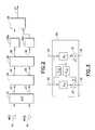
- FIG. 3is a schematic drawing of a stereo beam former used in the device shown in FIG. 1 ;
- FIG. 4is a graphical illustration of ratio thresholds/zones used in the device shown in FIG. 1 ;
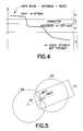
- FIG. 5is a diagram illustrating beam patterns used in the device shown in FIG. 1 ;
- FIG. 6is a block diagram of an exemplary method of the device shown in FIG. 1 ;
- FIG. 7is a block diagram of another exemplary method of the device shown in FIG. 1 .
- FIG. 1there is shown an exemplary electronic device 1 incorporating features of the invention.
- the inventionwill be described with reference to the exemplary embodiments shown in the drawings, it should be understood that the invention may be embodied in many alternate forms of embodiments.
- any suitable size, shape or type of elements or materialscould be used.
- the electronic device 1may be a wireless communication device, but it should be understood that the various embodiments of the invention are not restricted to wireless communication devices only.
- Various examples of the inventionmay be implemented in the desktop or laptop computers, for example. Additionally, features according to various exemplary embodiments of the invention could be used in any suitable type of hand-held portable electronic device such as a mobile phone, a gaming device, a music player, or a PDA, for example.
- the device 1may include multiple features or applications such as a camera, a music player, a game player, or an Internet browser, for example.
- the electronic device 1comprises at two audio input microphones 1 a , 1 b for inputting an audio signal for processing.
- the audio signalmay be amplified, by amplifier 3 and noise suppression may also be performed to produce an enhanced audio signal.
- the audio signalis divided into speech frames which means that a certain length of the audio signal is processed at one time.
- the length of the frameis usually a few milliseconds, for example 10 ms or 20 ms.
- the audio signalmay also be digitised in an analog/digital converter 4 .
- the analog/digital converter 4forms samples from the audio signal at certain intervals for example, at a certain sampling rate. After the analog/digital conversion, a speech frame may be represented by a set of samples.
- the electronic device 1may also have a speech processor 5 in which the audio signal processing can be at least partly performed.
- the speech processor 5may be, for example, a digital signal processor (DSP).
- the speech processormay also perform other operations, such as echo control in the uplink (transmission) and/or downlink (reception) of a wireless communication channel.
- the device 1 of FIG. 1may also comprise a control block 13 , in which the speech processor 5 and other controlling operations may be implemented, a keyboard 14 , a display 15 , and electronic circuitry, such as a memory 16 , for example.
- the samples of the audio signalmay be input to the speech processor 5 .
- the samplescan be processed on a frame-by-frame basis.
- the processingmay be performed in the time domain, or in the frequency domain or in both domains.
- the position detector 6 a and the spatial voice activity detector 6 bmay examine the speech samples to give an indication whether the samples of the current frame contain a speech or a non-speech signal.
- the indication from the detectors 6 a and 6 bmay be input to a third detector 6 c to make a final voice activity decision.
- the role of the position detector 6 amay be, for example, to decide if spatial VAD can be trusted or not. If the phone 1 is held differently than a design/orientation assumed by a beamformer, in the post processing stage only single channel methods may used for VAD.
- a third input to 6 cmay be the signals coming from the analog/digital converter 4 that may be used for single channel VAD, for example.
- Several operations within the electrical devicemay then utilise the voice activity decision. For example, a noise cancellation circuit may estimate and update a spectrum of the noise when the voice activity decision indicates that the signal does not contain speech.
- a noise cancellation circuitmay estimate and update a spectrum of the noise when the voice activity decision indicates that the signal does not contain speech.
- the position detector 6 amay be described in connection with the spatial voice activity detector 6 b , various exemplary embodiments of the invention may be provided without the spatial voice activity detector 6 b . Additionally, any suitable detector configuration may be provided. Further, although the position detector 6 a may be described as utilizing input from two microphones, embodiments of the invention may provide for the position detector 6 a to utilize input from more than two microphones.
- the position detector 6 aensures that two-microphone processing may be at least as good as single channel processing with one microphone. If the device, or phone, 1 is held in some odd manner (for example, a bottom of the phone pointing to a user's nose rather than to a user's mouth) two-microphone processing assuming optimal positioning could attenuate the user's own voice. Utilizing position detection, it may be possible to switch the phone to one-microphone processing, for example. In another non-limiting example, two-microphone processing may be provided even if the phone position is in an odd manner/orientation.
- the device 1may also comprise an audio/speech encoder (source encoding) 7 to encode the speech for transmission.
- the encoded speechmay be channel coded and transmitted by a transmitter 8 via a communication channel, for example a mobile communication network, to another electronic device such as a wireless communication device.
- the transmission chainmay further comprise channel coding (not shown in FIG. 1 ). However, any suitable transmission chain may be provided.
- a receiver 9for receiving signals from the communication channel.
- the receiver 9performs channel decoding and directs the channel decoded signals to a decoder 10 which reconstructs the speech frames.
- the speech frames and noiseare converted to analog signals by a digital to analog converter 11 .
- the analog signalsmay be converted to audible signal by a loudspeaker or an earpiece 12 .
- sampling frequency8 kHz is used in the analog to digital converter wherein the useful frequency range is about from 0 to 4 kHz which usually is enough for speech. It may also possible to use sampling frequencies other than 8 kHz, for example 16 kHz when also higher frequencies than 4 kHz could exist in the signal to be converted into digital form. However, any suitable sampling frequency may be utilized.
- the device 1may be configured to provide the amplifier 3 between the microphones 1 a , 1 b and the analog to digital converter 4 .
- the audio signals from the microphones 1 a , 1 bmay be input to the analog to digital converter without an amplifier (see FIG. 2 ).
- FIG. 2shows in more detail, the operation and configuration between the analog to digital converter and the position detector according to some examples of the invention.
- a filtering function 24 , a stereo beam former 29 , and power estimation units 25 b , 25 cmay be provided between the analog to digital converter 21 and the position detector 26 . It should be understood that although these components are described with reference to FIG. 2 , the filtering function 24 , the stereo beam former 29 , and the power estimation units 25 b , 25 c may be provided between the analog to digital converter 4 and the position detector 6 a in FIG. 1 . However, any suitable configuration may be provided.
- the audio signals 22 , 23are directed to the filtering function 24 , where the audio signals may be filtered.
- the filtering function 24may be provided to retain only those frequencies in the signals where the position detector operation is most effective.
- a low-pass filtermay be used.
- the low-pass filtermay have a cut-off frequency for example, at about 1 kHz to pass frequencies below that (for example, about 0-1 kHz).
- some other filterfor example, band-pass filter about 1-3 kHz may be used.
- any suitable filter configurationmay be provided.
- Filtered signals 33 , 34may then be input to the stereo beam former 29 .
- Signals 35 , 36 from the stereo beam former 29may then be input to the power estimation units 25 b , 25 c .
- the output signal 27 from the position detector 26may a binary value (1/0) for optimal/off-axis indication as described below in more detail. However, any suitable output signal may be provided.
- the filtering function 24locates after the stereo beam former 29 .
- the audio signals 22 , 23 originating from the first and the second microphones and the main and anti beam signals 35 and 36may be filtered before inputted to the power estimation units 25 b , 25 c (and to be used in the position detector 26 ).
- any suitable configurationmay be provided.
- FIG. 3shows the operation of the stereo beam former 29 in more detail.
- the beam former 29has a summation element 31 for receiving the first audio signal 34 processed by the transfer function Hc 1 and second audio signal 33 processed by the transfer function Hi 1 .
- a summation element 32receives the first audio signal 34 processed by the transfer function Hi 2 and second audio signal 33 processed by the transfer function Hc 2 .
- the output signals from the summation elements 31 , 32may be the main beam signal 35 and anti beam signal 36 which are directed to the power estimation units ( 25 b , 25 c in FIG. 2 ) and then used in the position detector 26 .
- the transfer functions Hi 1 , Hi 2 , Hc 1 and Hc 2may be designed/configured so that the main beam and anti beam signals 35 , 36 correspond to beams of 1 st order directional microphones.
- the transfer functions Hi 1 , Hi 2may be identical or different transfer functions.
- Hc 1 and Hc 2may be identical or different functions.
- both the main and anti beamsmay have a similar beam shape. Having different transfer functions enables to have different beam shapes for the main beam and anti beam.
- Ris the sensitivity, for example, the magnitude response in the function of the speech signal angle ⁇ .
- Kis a parameter describing the microphone types:
- the beam former 29may provide two beams, for example, main beam and anti beam signals 35 , 36 with opposite directional patters (K may thus be for example about 1 ⁇ 2).
- the position detector 26may classify between voice and noise based on a main-beam 35 —antibeam 36 ratio.
- b 1 and b 2refer to estimated mainbeam and antibeam signal powers, respectively. If the ratio b 1 /b 2 is very high, the phone is positioned correctly, if the ratio is moderate the phone is positioned incorrectly, and if it is very low (close to one) there is no local speech present at all.
- the position detector 26may be implemented by using several thresholds to decide when the ratio is high, moderate or low. Moreover, several counters may be used so that the position detector keeps its value for several seconds. Finally, a rough estimate of a background noise level may be estimated.
- the position detector 26may change its value from optimal to off-axis, or from off-axis back to optimal.
- the position detector 26may change its value from optimal to off-axis when the ratio b 1 /b 2 has not been very low for about 2.5 seconds, for example. However, any suitable time frame may be provided. The position detector 26 may also change its value from optimal to off-axis when the ratio has been between two thresholds that indicate moderate considerably more often than above another threshold that indicates high level. The position detector 26 may also change its value from optimal to off-axis when the signal level is considerably higher than the estimated background noise level (indicating speech presence).
- the position detector 26may change its value from off-axis back to optimal when the ratio has been more often very high (above certain threshold) considerably more often than moderate (between the other two thresholds).
- the thresholds concerning when the ratio b 1 /b 2 is high, moderate or lowmay depend on the positioning of the microphones and the design of the beam-former. Moreover, the thresholds may depend on the estimated background noise level.
- FIG. 4also depicts an exemplary graphical illustration of the basic functioning of the position detector 26 as described above.
- ratios in graphical zone Amay be a high ratio indicating an optimal position/orientation of the device 1 .
- Ratios in graphical zone Bmay be a moderate ratio indicating an off-axis position/orientation of the device 1 .
- Ratios in graphical zone Cmay be a low ratio indicating that the local speaker/user is not present (and therefore may be disregarded).
- Ratios in graphical zone Dmay indicate a transition between zones A and B (and therefore may be disregarded). It should be noted that although FIG. 4 illustrates four graphical zones, any suitable number of graphical zones may be provided.
- position detectionmay be computed using powers of two signals: main beam signal and anti beam signal.
- a position detector decisionmay then be computed, as described above using smoothed powers of these filtered signals.
- the position detector 26may be used for deciding if spatial VAD can be trusted or not. However, this may be provided as a non-limiting example, and the position detector may be used for other suitable purposes as well. It should be noted that although the position detector 26 may be described in connection with the spatial VAD, various exemplary embodiments of the invention may be provided without the spatial VAD. Additionally, any suitable detector configuration may be provided. Further, although the position detector 26 may be described as utilizing input from two microphones, embodiments of the invention may provide for the position detector 26 to utilize input from more than two microphones.
- FIG. 5illustrates a principle of main beams and anti beams in the context of mobile/wireless terminals where the two microphones and source 52 (for example, a user's mouth) are on a same line.
- the main beam and anti beam patternsmay be on a line joining the two microphones.
- FIG. 5shows a terminal 51 with microphone 1 (MIC 1 ) and microphone 2 (MIC 2 ) and the main beam 54 and anti beam 55 formed by the beam former 29 of FIG. 3 .
- Embodiments of the inventionare not limited to the use of two microphones.
- Having more than two microphonesmay allow for having, for example, several beams. Additionally, having more than two microphones may allow for having, for example, a narrower main beam instead of the main beam as shown in FIG. 5 . However, any suitable number of microphones or beam (mainbeam or antibeam) patterns may be provided.
- the spatial voice activity detector 6 b in FIG. 2may be any type of spatial voice activity detector.
- the spatial voice activity detectormay be provided as described in copending U.S. patent application Ser. No. 12/109,861 (titled “METHOD AND APPARATUS FOR VOICE ACTIVITY DETERMINATION”), filed on Apr. 25, 2008, which is hereby incorporated by reference in its entirety.
- the second voice activity detector 6 c in FIG. 1may be any type of voice activity detector.
- 3GPP standard TS 26.094(Mandatory speech codec speech processing functions; Adaptive Multi-Rate (AMR) speech codec; Voice Activity Detector (VAD)) provides one example implementation of the voice activity detector 6 b .
- AMRAdaptive Multi-Rate
- VADVoice Activity Detector
- the spatial VAD 6 cmay be any suitable kind of VAD.
- the classifier 6 cmay classify a speech frame as a noise frame (when spatial voice activity detector 6 b classifies a frame as a noise frame and position detector 6 a classifies optimal position).
- directional microphonescould be used instead of beams.
- a stereo beam formeris not required, but the ratio signal powers from the directional microphones (primary—secondary microphone ratio) may be used as decision criteria in the position detector.
- Suboptimal performancemay be obtained without filtering. Such frequency bands where there is only a very small difference in signal levels between the two signals, interfere rather than improve detection.
- Various embodiments of the inventionare directed to the field of digital signal processing, in speech enhancement.
- the intention in speech enhancementis to use mathematical methods for improving quality of speech, presented as digital signals.
- One embodiment of the inventionconsiders speech enhancement and especially noise suppression in such situations where there are two or more noisy speech signals available, for example, from two microphones.
- FIG. 6illustrates a method 100 .
- the method 100includes the following steps. Receiving a first audio signal (step 102 ). Receiving a second audio signal (step 104 ). Filtering the first and the second audio signals (step 106 ). Calculating a ratio of the first and the second audio signals (step 108 ). Determining a position of a device (step 110 ). Classifying the audio signals based on the calculated ratio and the determined position of the device (step 112 ). It should be noted that any of the above steps may be performed alone or in combination with one or more of the steps.
- FIG. 7illustrates a method 200 .
- the method 200includes the following steps. Receiving at least two audio signals. One of the at least two audio signals is received at a first microphone. Another one of the at least two audio signals is received at a second microphone (step 202 ). Determining a ratio of the at least two audio signals (step 204 ). Determining a position of a device based on the determined ratio (step 206 ). Switching a speech processor of the device from a two microphone processing mode to a one microphone processing mode based on, at least partially, the determined position of the device (step 208 ). It should be noted that any of the above steps may be performed alone or in combination with one or more of the steps.
- an apparatusincludes a first audio input device, a second audio input device, an analog to digital converter, a voice activity detector, and a position detector.
- the first audio input deviceis configured to receive a first audio signal.
- the second audio input deviceis configured to receive a second audio signal.
- the analog to digital converteris connected to the first and the second audio input devices.
- the voice activity detectoris connected to the analog to digital converter.
- the voice activity detectoris configured to receive input from the first and the second audio input devices.
- the position detectoris connected to the voice activity detector.
- the position detectoris configured to determine a position of the apparatus and classify the audio signals based on, at least partially, a ratio of the first audio signal and the second audio signal.
- a program storage devicereadable by a machine, tangibly embodying a program of instructions executable by the machine for performing operations to process audio speech signals.
- a first audio signalis received.
- a second audio signalis received.
- the first and the second audio signalsare filtered.
- a ratio of the first and the second audio signalsis calculated.
- a position of a portable deviceis determined.
- the audio signalsare classified based on the calculated ratio and the determined position of the portable device.
- components of the inventioncan be operationally coupled or connected and that any number or combination of intervening elements can exist (including no intervening elements).
- the connectionscan be direct or indirect and additionally there can merely be a functional relationship between components.
Landscapes
- Health & Medical Sciences (AREA)
- General Health & Medical Sciences (AREA)
- Otolaryngology (AREA)
- Physics & Mathematics (AREA)
- Engineering & Computer Science (AREA)
- Acoustics & Sound (AREA)
- Signal Processing (AREA)
- Circuit For Audible Band Transducer (AREA)
Abstract
Description
R(θ)=(1−K)+K*cos(θ) (1)
Claims (19)
Priority Applications (1)
| Application Number | Priority Date | Filing Date | Title |
|---|---|---|---|
| US12/429,785US8275136B2 (en) | 2008-04-25 | 2009-04-24 | Electronic device speech enhancement |
Applications Claiming Priority (3)
| Application Number | Priority Date | Filing Date | Title |
|---|---|---|---|
| US12547008P | 2008-04-25 | 2008-04-25 | |
| US12547508P | 2008-04-25 | 2008-04-25 | |
| US12/429,785US8275136B2 (en) | 2008-04-25 | 2009-04-24 | Electronic device speech enhancement |
Publications (2)
| Publication Number | Publication Date |
|---|---|
| US20090316918A1 US20090316918A1 (en) | 2009-12-24 |
| US8275136B2true US8275136B2 (en) | 2012-09-25 |
Family
ID=41431317
Family Applications (1)
| Application Number | Title | Priority Date | Filing Date |
|---|---|---|---|
| US12/429,785Active2031-01-16US8275136B2 (en) | 2008-04-25 | 2009-04-24 | Electronic device speech enhancement |
Country Status (1)
| Country | Link |
|---|---|
| US (1) | US8275136B2 (en) |
Cited By (3)
| Publication number | Priority date | Publication date | Assignee | Title |
|---|---|---|---|---|
| US20110071825A1 (en)* | 2008-05-28 | 2011-03-24 | Tadashi Emori | Device, method and program for voice detection and recording medium |
| US20140003622A1 (en)* | 2012-06-28 | 2014-01-02 | Broadcom Corporation | Loudspeaker beamforming for personal audio focal points |
| US10469944B2 (en) | 2013-10-21 | 2019-11-05 | Nokia Technologies Oy | Noise reduction in multi-microphone systems |
Families Citing this family (10)
| Publication number | Priority date | Publication date | Assignee | Title |
|---|---|---|---|---|
| EP1805918B1 (en) | 2004-09-27 | 2019-02-20 | Nielsen Media Research, Inc. | Methods and apparatus for using location information to manage spillover in an audience monitoring system |
| US8949120B1 (en) | 2006-05-25 | 2015-02-03 | Audience, Inc. | Adaptive noise cancelation |
| US8718290B2 (en) | 2010-01-26 | 2014-05-06 | Audience, Inc. | Adaptive noise reduction using level cues |
| US8473287B2 (en) | 2010-04-19 | 2013-06-25 | Audience, Inc. | Method for jointly optimizing noise reduction and voice quality in a mono or multi-microphone system |
| US9378754B1 (en)* | 2010-04-28 | 2016-06-28 | Knowles Electronics, Llc | Adaptive spatial classifier for multi-microphone systems |
| US20130282372A1 (en)* | 2012-04-23 | 2013-10-24 | Qualcomm Incorporated | Systems and methods for audio signal processing |
| US9197930B2 (en)* | 2013-03-15 | 2015-11-24 | The Nielsen Company (Us), Llc | Methods and apparatus to detect spillover in an audience monitoring system |
| KR101475894B1 (en)* | 2013-06-21 | 2014-12-23 | 서울대학교산학협력단 | Method and apparatus for improving disordered voice |
| US9769552B2 (en)* | 2014-08-19 | 2017-09-19 | Apple Inc. | Method and apparatus for estimating talker distance |
| US9848222B2 (en) | 2015-07-15 | 2017-12-19 | The Nielsen Company (Us), Llc | Methods and apparatus to detect spillover |
Citations (39)
| Publication number | Priority date | Publication date | Assignee | Title |
|---|---|---|---|---|
| EP0335521A1 (en) | 1988-03-11 | 1989-10-04 | BRITISH TELECOMMUNICATIONS public limited company | Voice activity detection |
| US5123887A (en) | 1990-01-25 | 1992-06-23 | Isowa Industry Co., Ltd. | Apparatus for determining processing positions of printer slotter |
| US5242364A (en) | 1991-03-26 | 1993-09-07 | Mathias Bauerle Gmbh | Paper-folding machine with adjustable folding rollers |
| US5276765A (en) | 1988-03-11 | 1994-01-04 | British Telecommunications Public Limited Company | Voice activity detection |
| US5383392A (en) | 1993-03-16 | 1995-01-24 | Ward Holding Company, Inc. | Sheet registration control |
| US5459814A (en) | 1993-03-26 | 1995-10-17 | Hughes Aircraft Company | Voice activity detector for speech signals in variable background noise |
| EP0734012A2 (en) | 1995-03-24 | 1996-09-25 | Mitsubishi Denki Kabushiki Kaisha | Signal discrimination circuit |
| US5657422A (en) | 1994-01-28 | 1997-08-12 | Lucent Technologies Inc. | Voice activity detection driven noise remediator |
| US5687241A (en) | 1993-12-01 | 1997-11-11 | Topholm & Westermann Aps | Circuit arrangement for automatic gain control of hearing aids |
| US5749067A (en) | 1993-09-14 | 1998-05-05 | British Telecommunications Public Limited Company | Voice activity detector |
| US5793642A (en) | 1997-01-21 | 1998-08-11 | Tektronix, Inc. | Histogram based testing of analog signals |
| US5822718A (en) | 1997-01-29 | 1998-10-13 | International Business Machines Corporation | Device and method for performing diagnostics on a microphone |
| US5963901A (en) | 1995-12-12 | 1999-10-05 | Nokia Mobile Phones Ltd. | Method and device for voice activity detection and a communication device |
| US6023674A (en) | 1998-01-23 | 2000-02-08 | Telefonaktiebolaget L M Ericsson | Non-parametric voice activity detection |
| US6182035B1 (en) | 1998-03-26 | 2001-01-30 | Telefonaktiebolaget Lm Ericsson (Publ) | Method and apparatus for detecting voice activity |
| WO2001037265A1 (en) | 1999-11-15 | 2001-05-25 | Nokia Corporation | Noise suppression |
| US20010056291A1 (en) | 2000-06-19 | 2001-12-27 | Yitzhak Zilberman | Hybrid middle ear/cochlea implant system |
| US6427134B1 (en) | 1996-07-03 | 2002-07-30 | British Telecommunications Public Limited Company | Voice activity detector for calculating spectral irregularity measure on the basis of spectral difference measurements |
| US20020103636A1 (en) | 2001-01-26 | 2002-08-01 | Tucker Luke A. | Frequency-domain post-filtering voice-activity detector |
| US6449593B1 (en) | 2000-01-13 | 2002-09-10 | Nokia Mobile Phones Ltd. | Method and system for tracking human speakers |
| US20020138254A1 (en) | 1997-07-18 | 2002-09-26 | Takehiko Isaka | Method and apparatus for processing speech signals |
| US6556967B1 (en) | 1999-03-12 | 2003-04-29 | The United States Of America As Represented By The National Security Agency | Voice activity detector |
| US6574592B1 (en) | 1999-03-19 | 2003-06-03 | Kabushiki Kaisha Toshiba | Voice detecting and voice control system |
| US6647365B1 (en) | 2000-06-02 | 2003-11-11 | Lucent Technologies Inc. | Method and apparatus for detecting noise-like signal components |
| US20030228023A1 (en) | 2002-03-27 | 2003-12-11 | Burnett Gregory C. | Microphone and Voice Activity Detection (VAD) configurations for use with communication systems |
| US6675125B2 (en) | 1999-11-29 | 2004-01-06 | Syfx | Statistics generator system and method |
| US20040042626A1 (en) | 2002-08-30 | 2004-03-04 | Balan Radu Victor | Multichannel voice detection in adverse environments |
| US20040117176A1 (en) | 2002-12-17 | 2004-06-17 | Kandhadai Ananthapadmanabhan A. | Sub-sampled excitation waveform codebooks |
| US20040122667A1 (en) | 2002-12-24 | 2004-06-24 | Mi-Suk Lee | Voice activity detector and voice activity detection method using complex laplacian model |
| EP1453349A2 (en) | 2003-02-25 | 2004-09-01 | AKG Acoustics GmbH | Self-calibration of a microphone array |
| US20050108004A1 (en) | 2003-03-11 | 2005-05-19 | Takeshi Otani | Voice activity detector based on spectral flatness of input signal |
| US20050147258A1 (en) | 2003-12-24 | 2005-07-07 | Ville Myllyla | Method for adjusting adaptation control of adaptive interference canceller |
| US20060053007A1 (en) | 2004-08-30 | 2006-03-09 | Nokia Corporation | Detection of voice activity in an audio signal |
| WO2007013525A1 (en) | 2005-07-26 | 2007-02-01 | Honda Motor Co., Ltd. | Sound source characteristic estimation device |
| US7203323B2 (en) | 2003-07-25 | 2007-04-10 | Microsoft Corporation | System and process for calibrating a microphone array |
| US20070136053A1 (en) | 2005-12-09 | 2007-06-14 | Acoustic Technologies, Inc. | Music detector for echo cancellation and noise reduction |
| WO2007138503A1 (en) | 2006-05-31 | 2007-12-06 | Philips Intellectual Property & Standards Gmbh | Method of driving a speech recognition system |
| US20080317259A1 (en) | 2006-05-09 | 2008-12-25 | Fortemedia, Inc. | Method and apparatus for noise suppression in a small array microphone system |
| US20090089053A1 (en) | 2007-09-28 | 2009-04-02 | Qualcomm Incorporated | Multiple microphone voice activity detector |
- 2009
- 2009-04-24USUS12/429,785patent/US8275136B2/enactiveActive
Patent Citations (41)
| Publication number | Priority date | Publication date | Assignee | Title |
|---|---|---|---|---|
| EP0335521A1 (en) | 1988-03-11 | 1989-10-04 | BRITISH TELECOMMUNICATIONS public limited company | Voice activity detection |
| US5276765A (en) | 1988-03-11 | 1994-01-04 | British Telecommunications Public Limited Company | Voice activity detection |
| US5123887A (en) | 1990-01-25 | 1992-06-23 | Isowa Industry Co., Ltd. | Apparatus for determining processing positions of printer slotter |
| US5242364A (en) | 1991-03-26 | 1993-09-07 | Mathias Bauerle Gmbh | Paper-folding machine with adjustable folding rollers |
| US5383392A (en) | 1993-03-16 | 1995-01-24 | Ward Holding Company, Inc. | Sheet registration control |
| US5459814A (en) | 1993-03-26 | 1995-10-17 | Hughes Aircraft Company | Voice activity detector for speech signals in variable background noise |
| US5749067A (en) | 1993-09-14 | 1998-05-05 | British Telecommunications Public Limited Company | Voice activity detector |
| US5687241A (en) | 1993-12-01 | 1997-11-11 | Topholm & Westermann Aps | Circuit arrangement for automatic gain control of hearing aids |
| US5657422A (en) | 1994-01-28 | 1997-08-12 | Lucent Technologies Inc. | Voice activity detection driven noise remediator |
| EP0734012A2 (en) | 1995-03-24 | 1996-09-25 | Mitsubishi Denki Kabushiki Kaisha | Signal discrimination circuit |
| US5963901A (en) | 1995-12-12 | 1999-10-05 | Nokia Mobile Phones Ltd. | Method and device for voice activity detection and a communication device |
| US6427134B1 (en) | 1996-07-03 | 2002-07-30 | British Telecommunications Public Limited Company | Voice activity detector for calculating spectral irregularity measure on the basis of spectral difference measurements |
| US5793642A (en) | 1997-01-21 | 1998-08-11 | Tektronix, Inc. | Histogram based testing of analog signals |
| US5822718A (en) | 1997-01-29 | 1998-10-13 | International Business Machines Corporation | Device and method for performing diagnostics on a microphone |
| US20020138254A1 (en) | 1997-07-18 | 2002-09-26 | Takehiko Isaka | Method and apparatus for processing speech signals |
| US6023674A (en) | 1998-01-23 | 2000-02-08 | Telefonaktiebolaget L M Ericsson | Non-parametric voice activity detection |
| US6182035B1 (en) | 1998-03-26 | 2001-01-30 | Telefonaktiebolaget Lm Ericsson (Publ) | Method and apparatus for detecting voice activity |
| US6556967B1 (en) | 1999-03-12 | 2003-04-29 | The United States Of America As Represented By The National Security Agency | Voice activity detector |
| US6574592B1 (en) | 1999-03-19 | 2003-06-03 | Kabushiki Kaisha Toshiba | Voice detecting and voice control system |
| US6810273B1 (en) | 1999-11-15 | 2004-10-26 | Nokia Mobile Phones | Noise suppression |
| WO2001037265A1 (en) | 1999-11-15 | 2001-05-25 | Nokia Corporation | Noise suppression |
| US6675125B2 (en) | 1999-11-29 | 2004-01-06 | Syfx | Statistics generator system and method |
| US6449593B1 (en) | 2000-01-13 | 2002-09-10 | Nokia Mobile Phones Ltd. | Method and system for tracking human speakers |
| US6647365B1 (en) | 2000-06-02 | 2003-11-11 | Lucent Technologies Inc. | Method and apparatus for detecting noise-like signal components |
| US20010056291A1 (en) | 2000-06-19 | 2001-12-27 | Yitzhak Zilberman | Hybrid middle ear/cochlea implant system |
| US20020103636A1 (en) | 2001-01-26 | 2002-08-01 | Tucker Luke A. | Frequency-domain post-filtering voice-activity detector |
| US20030228023A1 (en) | 2002-03-27 | 2003-12-11 | Burnett Gregory C. | Microphone and Voice Activity Detection (VAD) configurations for use with communication systems |
| US20040042626A1 (en) | 2002-08-30 | 2004-03-04 | Balan Radu Victor | Multichannel voice detection in adverse environments |
| US20040117176A1 (en) | 2002-12-17 | 2004-06-17 | Kandhadai Ananthapadmanabhan A. | Sub-sampled excitation waveform codebooks |
| US20040122667A1 (en) | 2002-12-24 | 2004-06-24 | Mi-Suk Lee | Voice activity detector and voice activity detection method using complex laplacian model |
| EP1453349A2 (en) | 2003-02-25 | 2004-09-01 | AKG Acoustics GmbH | Self-calibration of a microphone array |
| US20050108004A1 (en) | 2003-03-11 | 2005-05-19 | Takeshi Otani | Voice activity detector based on spectral flatness of input signal |
| US7203323B2 (en) | 2003-07-25 | 2007-04-10 | Microsoft Corporation | System and process for calibrating a microphone array |
| US20050147258A1 (en) | 2003-12-24 | 2005-07-07 | Ville Myllyla | Method for adjusting adaptation control of adaptive interference canceller |
| US20060053007A1 (en) | 2004-08-30 | 2006-03-09 | Nokia Corporation | Detection of voice activity in an audio signal |
| WO2007013525A1 (en) | 2005-07-26 | 2007-02-01 | Honda Motor Co., Ltd. | Sound source characteristic estimation device |
| US20080199024A1 (en) | 2005-07-26 | 2008-08-21 | Honda Motor Co., Ltd. | Sound source characteristic determining device |
| US20070136053A1 (en) | 2005-12-09 | 2007-06-14 | Acoustic Technologies, Inc. | Music detector for echo cancellation and noise reduction |
| US20080317259A1 (en) | 2006-05-09 | 2008-12-25 | Fortemedia, Inc. | Method and apparatus for noise suppression in a small array microphone system |
| WO2007138503A1 (en) | 2006-05-31 | 2007-12-06 | Philips Intellectual Property & Standards Gmbh | Method of driving a speech recognition system |
| US20090089053A1 (en) | 2007-09-28 | 2009-04-02 | Qualcomm Incorporated | Multiple microphone voice activity detector |
Non-Patent Citations (20)
| Title |
|---|
| "Mandatory Speech Codec speech processing functions AMR speech codec" Voice Activity Detector (VAD), Technical Specification Group Services and System Aspects; 3rd Generation Partnership Project; 3G TS 26.094 version 3.0.0, date Oct. 1999, 29 Pages. |
| Buck, et al., "Self-calibrating microphone arrays for speech signal acquisition: a systematic approach", vol. 86 , Issue 6, Jun. 2006, 1230-1238 pages. |
| Extended European Search Report received for corresponding European Patent Application No. 05775189.3, dated Nov. 3, 2008, 7 Pages. |
| File history for related (abandoned) U.S. Appl. No. 11/214,454, filed Aug. 29, 2005, 200 pages. |
| Furui, et al., Advances in Speech signal processing, Newyork: Marcel Dekker, 1992. |
| Gazor, et al., "A soft voice activity detector based on a Laplacian-Gaussian model", IEEE Transaction Speech and Audio Processing, vol. 11, No. 5, Sep. 2003, 498-505 pages. |
| Gray, Jr., et al, "A spectral-flatness measure for studying the auto correlation method of linear prediction of speech analysis", IEEE Transaction Acoustics, Speech, Signal Processing, vol. ASSP-22, Jun. 1974, 207-216 pages. |
| Hansler, et al., Acoustic echo and noise control: A Practical Approach, John Wiley & Sons, Inc. Hoboken, New Jersey, 2004. |
| Hoffman, Michael W., et al., "GSC-Based Spatial Voice Activity Detection for Enhanced Speech Coding in the Presence of Competing Speech", IEEE Transactions on Speech and Audio Processing, vol. 9, No. 2, Mar. 2001, pp. 175-179. |
| Hua, et al. "A new self-calibration technique for adaptive microphone arrays", Media and Information Research Laboratories, NEC Corporation, Kawasaki 211-8666, Japan, 4 Pages. |
| International Search Report and Written Opinion received in corresponding PCT Application No. PCT/FI2009/050302 dated Nov. 21, 2005, 11 pages. |
| International Search Report and Written Opinion received in corresponding PCT Application No. PCT/FI2009/050314 dated Sep. 3, 2009, 10 pages. |
| International Search Report and Written Opinion received in corresponding PCT Application No. PCT/IB2009/005374, dated, Aug. 12, 2009, 14 pages. |
| Ivan Tashev, "Gain Self-Calibration Procedure for Microphone Arrays", Microsoft Research, One Microsoft Way, Redmond, WA 98052, USA, 4 Pages. |
| Marzinzik, et al., "Speech pause detection for noise spectrum estimation by tracking power envelope dynamics", IEEE Transaction Speech and Audio Processing, vol. 10, No. 2, Feb. 2002, 109-118 pages. |
| Office Action received in related U.S. Appl. No. 12/109,861, dated May 5, 2011, 7 pages. |
| Prasad et al., "Comparison of Voice Activity Detection Algorithms for VoIP", Proceedings of the 7th International Symposium on Computers and Communications, dated Jul. 1-4, 2002, pp. 530-535. |
| Teutsch, et al. "An Adaptive Close-Talking Microphone Array", New Paltz, New York, Oct. 21-24, 2001, 4 Pages. |
| Widrow, Bernard, "Adaptive Noise Cancelling: Principles and Applications", Proceedings of the IEEE, vol. 63, No. 12, Dec. 1975, pp. 1692-1716. |
| Zhibo Cai, et al., "A knowledge based real-time speech detector for microphone array video conferencing system" Signal Processing, 2002 6th International Conference on Aug. 26-30, 2002, Piscataway, New Jersey, USA, IEEE, vol. 1, pp. 350-353. |
Cited By (5)
| Publication number | Priority date | Publication date | Assignee | Title |
|---|---|---|---|---|
| US20110071825A1 (en)* | 2008-05-28 | 2011-03-24 | Tadashi Emori | Device, method and program for voice detection and recording medium |
| US8589152B2 (en)* | 2008-05-28 | 2013-11-19 | Nec Corporation | Device, method and program for voice detection and recording medium |
| US20140003622A1 (en)* | 2012-06-28 | 2014-01-02 | Broadcom Corporation | Loudspeaker beamforming for personal audio focal points |
| US9119012B2 (en)* | 2012-06-28 | 2015-08-25 | Broadcom Corporation | Loudspeaker beamforming for personal audio focal points |
| US10469944B2 (en) | 2013-10-21 | 2019-11-05 | Nokia Technologies Oy | Noise reduction in multi-microphone systems |
Also Published As
| Publication number | Publication date |
|---|---|
| US20090316918A1 (en) | 2009-12-24 |
Similar Documents
| Publication | Publication Date | Title |
|---|---|---|
| US8275136B2 (en) | Electronic device speech enhancement | |
| US8244528B2 (en) | Method and apparatus for voice activity determination | |
| US8311817B2 (en) | Systems and methods for enhancing voice quality in mobile device | |
| US9997173B2 (en) | System and method for performing automatic gain control using an accelerometer in a headset | |
| US8600454B2 (en) | Decisions on ambient noise suppression in a mobile communications handset device | |
| US8626498B2 (en) | Voice activity detection based on plural voice activity detectors | |
| US9467779B2 (en) | Microphone partial occlusion detector | |
| US9100756B2 (en) | Microphone occlusion detector | |
| US10186276B2 (en) | Adaptive noise suppression for super wideband music | |
| US20170365249A1 (en) | System and method of performing automatic speech recognition using end-pointing markers generated using accelerometer-based voice activity detector | |
| JP5410603B2 (en) | System, method, apparatus, and computer-readable medium for phase-based processing of multi-channel signals | |
| US8428661B2 (en) | Speech intelligibility in telephones with multiple microphones | |
| US10271135B2 (en) | Apparatus for processing of audio signals based on device position | |
| KR101532153B1 (en) | Systems, methods, and apparatus for voice activity detection | |
| US20120123775A1 (en) | Post-noise suppression processing to improve voice quality | |
| US8750526B1 (en) | Dynamic bandwidth change detection for configuring audio processor | |
| US8924206B2 (en) | Electrical apparatus and voice signals receiving method thereof | |
| Li et al. | Robust speech coding using microphone arrays |
Legal Events
| Date | Code | Title | Description |
|---|---|---|---|
| AS | Assignment | Owner name:NOKIA CORPORATION, FINLAND Free format text:ASSIGNMENT OF ASSIGNORS INTEREST;ASSIGNORS:NIEMISTO, RIITTA ELINA;VARTIAINEN, JUKKA PETTERI;REEL/FRAME:023596/0030;SIGNING DATES FROM 20090824 TO 20090827 Owner name:NOKIA CORPORATION, FINLAND Free format text:ASSIGNMENT OF ASSIGNORS INTEREST;ASSIGNORS:NIEMISTO, RIITTA ELINA;VARTIAINEN, JUKKA PETTERI;SIGNING DATES FROM 20090824 TO 20090827;REEL/FRAME:023596/0030 | |
| FEPP | Fee payment procedure | Free format text:PAYOR NUMBER ASSIGNED (ORIGINAL EVENT CODE: ASPN); ENTITY STATUS OF PATENT OWNER: LARGE ENTITY | |
| STCF | Information on status: patent grant | Free format text:PATENTED CASE | |
| FPAY | Fee payment | Year of fee payment:4 | |
| AS | Assignment | Owner name:NOKIA TECHNOLOGIES OY, FINLAND Free format text:ASSIGNMENT OF ASSIGNORS INTEREST;ASSIGNOR:NOKIA CORPORATION;REEL/FRAME:040812/0679 Effective date:20150116 | |
| MAFP | Maintenance fee payment | Free format text:PAYMENT OF MAINTENANCE FEE, 8TH YEAR, LARGE ENTITY (ORIGINAL EVENT CODE: M1552); ENTITY STATUS OF PATENT OWNER: LARGE ENTITY Year of fee payment:8 | |
| MAFP | Maintenance fee payment | Free format text:PAYMENT OF MAINTENANCE FEE, 12TH YEAR, LARGE ENTITY (ORIGINAL EVENT CODE: M1553); ENTITY STATUS OF PATENT OWNER: LARGE ENTITY Year of fee payment:12 |