US8275090B2 - Multi-mode tomosynthesis/mammography gain calibration and image correction using gain map information from selected projection angles - Google Patents
Multi-mode tomosynthesis/mammography gain calibration and image correction using gain map information from selected projection anglesDownload PDFInfo
- Publication number
- US8275090B2 US8275090B2US13/196,518US201113196518AUS8275090B2US 8275090 B2US8275090 B2US 8275090B2US 201113196518 AUS201113196518 AUS 201113196518AUS 8275090 B2US8275090 B2US 8275090B2
- Authority
- US
- United States
- Prior art keywords
- gain
- breast
- projection
- tomosynthesis
- images
- Prior art date
- Legal status (The legal status is an assumption and is not a legal conclusion. Google has not performed a legal analysis and makes no representation as to the accuracy of the status listed.)
- Active
Links
Images


Classifications
- A—HUMAN NECESSITIES
- A61—MEDICAL OR VETERINARY SCIENCE; HYGIENE
- A61B—DIAGNOSIS; SURGERY; IDENTIFICATION
- A61B6/00—Apparatus or devices for radiation diagnosis; Apparatus or devices for radiation diagnosis combined with radiation therapy equipment
- A61B6/58—Testing, adjusting or calibrating thereof
- A61B6/582—Calibration
- A61B6/585—Calibration of detector units
- A—HUMAN NECESSITIES
- A61—MEDICAL OR VETERINARY SCIENCE; HYGIENE
- A61B—DIAGNOSIS; SURGERY; IDENTIFICATION
- A61B6/00—Apparatus or devices for radiation diagnosis; Apparatus or devices for radiation diagnosis combined with radiation therapy equipment
- A61B6/02—Arrangements for diagnosis sequentially in different planes; Stereoscopic radiation diagnosis
- A61B6/025—Tomosynthesis
- A—HUMAN NECESSITIES
- A61—MEDICAL OR VETERINARY SCIENCE; HYGIENE
- A61B—DIAGNOSIS; SURGERY; IDENTIFICATION
- A61B6/00—Apparatus or devices for radiation diagnosis; Apparatus or devices for radiation diagnosis combined with radiation therapy equipment
- A61B6/42—Arrangements for detecting radiation specially adapted for radiation diagnosis
- A61B6/4208—Arrangements for detecting radiation specially adapted for radiation diagnosis characterised by using a particular type of detector
- A61B6/4233—Arrangements for detecting radiation specially adapted for radiation diagnosis characterised by using a particular type of detector using matrix detectors
- A—HUMAN NECESSITIES
- A61—MEDICAL OR VETERINARY SCIENCE; HYGIENE
- A61B—DIAGNOSIS; SURGERY; IDENTIFICATION
- A61B6/00—Apparatus or devices for radiation diagnosis; Apparatus or devices for radiation diagnosis combined with radiation therapy equipment
- A61B6/50—Apparatus or devices for radiation diagnosis; Apparatus or devices for radiation diagnosis combined with radiation therapy equipment specially adapted for specific body parts; specially adapted for specific clinical applications
- A61B6/502—Apparatus or devices for radiation diagnosis; Apparatus or devices for radiation diagnosis combined with radiation therapy equipment specially adapted for specific body parts; specially adapted for specific clinical applications for diagnosis of breast, i.e. mammography
- G—PHYSICS
- G06—COMPUTING OR CALCULATING; COUNTING
- G06T—IMAGE DATA PROCESSING OR GENERATION, IN GENERAL
- G06T11/00—2D [Two Dimensional] image generation
- G06T11/003—Reconstruction from projections, e.g. tomography
- G06T11/005—Specific pre-processing for tomographic reconstruction, e.g. calibration, source positioning, rebinning, scatter correction, retrospective gating
- A—HUMAN NECESSITIES
- A61—MEDICAL OR VETERINARY SCIENCE; HYGIENE
- A61B—DIAGNOSIS; SURGERY; IDENTIFICATION
- A61B6/00—Apparatus or devices for radiation diagnosis; Apparatus or devices for radiation diagnosis combined with radiation therapy equipment
- A61B6/04—Positioning of patients; Tiltable beds or the like
- A61B6/0407—Supports, e.g. tables or beds, for the body or parts of the body
- A61B6/0421—Supports, e.g. tables or beds, for the body or parts of the body with immobilising means
- A—HUMAN NECESSITIES
- A61—MEDICAL OR VETERINARY SCIENCE; HYGIENE
- A61B—DIAGNOSIS; SURGERY; IDENTIFICATION
- A61B6/00—Apparatus or devices for radiation diagnosis; Apparatus or devices for radiation diagnosis combined with radiation therapy equipment
- A61B6/58—Testing, adjusting or calibrating thereof
- A61B6/582—Calibration
- A61B6/583—Calibration using calibration phantoms
Definitions
- This patent specificationis in the field of medical x-ray imaging and more specifically relates to multi-mode tomosynthesis/mammography methods and systems for imaging a patient's breast and to gain calibration and correction of breast images in such methods and systems. More specifically the patent specification relates to the generation and use of gain maps in x-ray breast imaging.
- X-ray mammographycurrently is the most widely used tool for early detection and diagnosis, and is the modality approved by the U.S. Food and Drug Administration to screen for breast cancer in women who do not show symptoms of breast disease.
- Breast tomosynthesisis a more recently developed modality and is expected to become more widely used, for diagnosis and possibly as a screening tool.
- An even more recent developmentis multi-modality breast imaging systems that have both mammography and tomosynthesis capabilities and can provide either or both of mammograms and tomosynthesis images of a patient's breast, in the same or different immobilizations of the breast.
- a typical x-ray mammography systemimmobilizes a patient's breast on a breast platform that is between an x-ray source and an x-ray imaging receptor, and takes a projection x-ray image (called here a conventional mammogram or simply mammogram) using a collimated cone or pyramid or fan beam of x-rays at appropriate factors such as mA (current), kVp (voltage) or keV (energy), and msec (exposure time).
- the x-ray sourcetypically is an x-ray tube operating at or in the neighborhood of 25-30 kVp, using a molybdenum, rhodium, or tungsten rotating anode with a focal spot of about 0.3 to 0.4 mm and, in some cases, 0.1 mm or less.
- An anti-scatter grid between the breast and the imagercan be used to reduce the effects of x-ray scatter.
- the breastis compressed to reduce patient motion and also for reasons such as reducing scatter, separating overlapping structures in the breast, reducing the x-ray thickness of the imaged breast and making it more uniform, and providing more uniform x-ray exposure.
- the imagerhas been a film/screen unit in which the x-rays impinging on the screen generate light that exposes the film.
- mammography systems using electronic digital flat panel x-ray receptorshave made significant inroads.
- a SeleniaTM digital mammography system with such a digital flat panel x-ray receptor or imageris offered by Lorad, a division of the assignee hereof, Hologic, Inc. of Bedford, Mass. See brochure “Lorad SeleniaTM” Document B-BI-SEO US/Intl (5/06) copyright Hologic 2006. Digital mammography has significant advantages and in time may fully supplant film/screen systems.
- Digital tomosynthesisalso has made advances and the assignee hereof has exhibited breast tomosynthesis systems at trade shows and has carried out clinical testing. It is a three-dimensional process in which several two-dimensional projection views are acquired at respective different angles but at lower x-ray dose each compared to a conventional mammogram, and are reconstructed into tomosynthesis slice views that can be along any desired plane in the breast and can represent any thickness of breast tissue.
- the breastis still immobilized, by compression to the same or lesser extent than in conventional mammography. See, e.g., International Application WO 2006/058160 A2 published under the Patent Cooperation Treaty on Jun. 1, 2006 and Patent Application Publication No. 2001/0038681 A1 PCT application International Publication No.
- the assignee hereofhas developed multi-mode systems in which the same x-ray data acquisition equipment can be used for either or both of mammography and tomosynthesis imaging.
- a mammogram and tomosynthesis imagescan be acquired while the patient's breast remains immobilized, or they can be acquired at different times or patient's visits.
- One such systemis known as Selenia DimensionsTM and another is known as GeminiTM. See Smith, A., Fundamentals of Breast Tomosynthesis, White Paper, Hologic Inc., WP-00007, June 2008. Additional information regarding digital mammography, tomosynthesis and multi-mode systems offered by the common assignee can be found at ⁇ www.hologic.com>.
- the imaging receptormay comprise a two-dimensional array of millions of imaging pixels, and there may be inherent differences in the response of different imaging pixels to impinging x-rays.
- pixel valueelectrical output signal
- incident x-ray intensity across the detector surfaceusually is non-uniform; for example, due to the “heel effect” the x-ray intensity drops along the direction from the chest wall to the nipple.
- the gain mapis stored in the imaging system and, when x-ray images of a patient's breast are taken, software in the system corrects the acquired pixel values according to the gain map to bring them closer to the pixel values that would have been produced if all the imaging pixels had the same response to uniform exposure to x-ray energy.
- Gain calibrationthus can be used to compensate for sensitivity differences between detector pixels and non-uniform x-ray field intensity given a particular physical relationship between the x-ray source and imaging detector.
- tomosynthesis imagingis characterized by a much greater number of changes in x-ray source projection angle during x-ray exposure, much lower x-ray exposure of the breast at any one of the projection angles, and other significant differences from conventional mammography imaging.
- gain maps typical for conventional mammographycannot be expected to work well in tomosynthesis image acquisition and image correction, particularly if the tomosynthesis projection angles may change depending on imaging protocol or decisions or preferences of the health professional in charge.
- the systemgenerates at least one initial gain map G(p) for each projection angle “p” from the projection images T(p,n) for the same projection angle “p,” by evaluating differences between expected and actual characteristics of pixel values in the projection images T(p.n).
- the systemthen forms one or more enhanced gain maps EG(p), using the initial gain maps G(p) in a computer-implemented process that combines selected parameters of the initial gain maps G(p).
- the first and second sets of projection anglesmay be the same or may differ in number of angles, in angular span, and in angle value.
- the systemgain-corrects the tomosynthesis x-ray images T′(p′) of the patient's breast using the enhanced gain maps EG(p) in a computer-implemented process to thereby produce gain-corrected breast images that can be further processed and displayed, e.g., to a health professional, or sent for storage and/or review to a remote location such as a PACS system.
- a “separate” enhanced gain mapis generated for each of the second projection angles from initial gain maps for several but not all of the first projection angles.
- a “single” enhanced gain mapis generated from the initial gain maps for all of the first projection angles and is used to gain-correct breast images for all if the second projection angles.
- a “single” gain mapis generated for each of the second projection angles from the initial gain maps for all the first projection angles, but by weighting the initial gain maps differently for each of the second projection angles.
- an “individual” enhanced gain mapis generated for each of the second projection angles from only the initial gain map for the same or closest first projection angle.
- Enhanced gain mapsalternatively are generated more directly from the phantom projection images T(p,n), without first generating initial gain maps. For example, to generate a “separate” enhanced gain map for a given second projection angle, the phantom projection images T(p,n) for several first projection angle are combined, e.g., averaged, and the differences between expected and measured pixel values, or simply the differences between measured pixel values, are used to generate an enhanced gain map for the given second projection angle.
- a tablecan be created and stored in a tomosynthesis and/or mammography system that contains gain map information from which a gain map appropriate for gain-correcting a breast image can be derived even in a case when the breast image is acquired at a projection angle in which no phantom images were acquired and/of the phantom images were acquired differently, e.g., with a different x-ray filter or a different set of technique factors such as kV and mAs.
- the tablecan store gain maps for first projection angles that do not include a particular second projection angle at which a breast image is acquired. In that case, an enhanced gain map for gain-correcting the breast image is generated by interpolation addressing the closest first projection angles. Similar interpolation can be used when the breast image is taken with an x-ray filter or a set of technique factors that differ from those of gain map information in the table.
- FIG. 1illustrates in block diagram form certain components of a breast tomosynthesis system such as said Selenia DimensionsTM and GeminiTM systems developed by the assignee hereof.
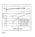
- FIG. 2illustrates graphs of CNR of a tomosynthesis projection image vs. number of scans of a gain calibration phantom used to generate different gain maps according to one disclosed embodiment.
- FIG. 3illustrates graphs of CNR of a tomosynthesis projection image vs. number of scans of a gain calibration phantom used to generate different gain maps according to another disclosed embodiment.
- FIG. 4illustrated graphs of x-ray dose penalty vs. number of scans when using differently generated gain maps.
- FIG. 5illustrates an example of information flow in generating gain map information and gain-correcting tomosynthesis breast images.
- a multi-mode tomosynthesis/mammography gantrycomprises an image acquisition unit comprising an x-ray source 100 on one side of an immobilizer 102 , and an x-ray receptor 104 on the other side.
- Immobilizer 102immobilizes a patient's breast or a phantom for tomosynthesis or for mammography x-ray exposures.
- source 100 , immobilizer 102 and receptor 104remain in a fixed rotational relationship and move together under the control of controller 106 from one imaging position to another, e.g., from a CC position to an MLO position.
- scan motion controller 106moves source 100 relative to immobilizer 102 .
- Receptor 104also moves relative to immobilizer 102 during tomosynthesis data acquisition in said Selenia DimensionsTM system but may move differently, or not at all, in other systems.
- the motionis motorized.
- the source motioncan be continuous or the source can stop and emit imaging x-rays at one projection angle before moving to another projection angle.
- X-ray receptor 104provides projection image data in the form of an array of pixel values related to incident x-ray energy, and can be a Selenium-based, direct conversion digital x-ray receptor available from the assignee hereof.
- a calibration phantomthat typically is a flat-field phantom (not shown) is secured in the immobilizer, in a position similar to that of a patient's breast when x-rays of a patient's breast are taken.
- the systemis operated in a mammography mode and x-ray projection images of the phantom are taken. Different sets of projection images can be taken for different x-ray filter and/or different technique factors.
- Each projection x-ray image T(p,n)is represented by of pixel values related to the x-rays received at respective pixel positions of an array of imaging pixels in receptor 104 .
- the number of the second projection anglescan be different, e.g., greater, than the number of first projection angles, and/or some or all of the second projection angles can be non-coincident with any of the first projection angles.
- the number of second projection angles used to acquire breast images in a tomosynthesis sequencecan be greater than the number of first projection angles used in acquiring phantom images, e.g., the initial gain maps G(p) may be derived from phantom projection images taken at first projection angles spaced angularly by 2° over a first angular interval but tomosynthesis projection images of a patient's breast may be taken over the same angular interval but at second projection angles spaced apart by 1°.
- the second projection anglesmay range over a different or a greater angular interval than the first projection angles, and some or all of the second projection angles may not coincide with any of the first projection angles. If initial gain maps are generated from phantom images taken with different x-ray filters or at different technique factors, the breast images may be taken with filters or at technique factors that do not coincide with some or all of those used in taking the phantom images.
- a workstation coupled to the acquisition unitcomprises processing equipment that receives from receptor 104 (a) the projection images of the phantom taken in the mammography mode as well as the images T(p,n) taken in the tomosynthesis mode of the system, and (b) the mammograms and the projection images T(p′) the patient's breast taken in the tomosynthesis mode of the system.
- the workstationpreferably includes a pre-processor 108 that carries out conventional preliminary processing of the image pixel values.
- the mammograms and the tomosynthesis images of the patient's breastare supplied to a unit 114 from pre-processor 112 or directly from receptor 104 .
- the phantom imagesare supplied to a system for generating gain maps, from pre-processor 108 if desired or directly from receptor 104 .
- the gain map generatorcan comprise an initial gain map generator 110 that supplies its output to an enhanced map generator 112 , or a generator that produced enhanced gain maps more directly from the phantom projection images.
- the breast images and the enhanced gain mapsare supplied to a unit 114 that carries out functions such as gain-correcting the breast images using the gain calibration maps, displaying the resulting gain-corrected images, storing images and other information, providing system control, etc.
- Image generator 114may also carry out other processing of the image data, such as CAD (compute-aided detection) to identify suspected abnormalities or selected other characteristics, processing to prepare images for display and to control the display, to prepare images for storage such as DICOM-compliant storage, to provide an interface for an x-ray technician or other health professional, and to provide other control functions and carry out other processing.
- CADcompute-aided detection
- the phantom images T(p,n) from pre-processor 110are supplied to an initial gain map generator 110 that generates an initial gain map G(p) for each of the P first projection angles used in acquiring the projection images T(p,n), using for any given initial gain map G(p) the N projection images T(p,n) of the calibration phantom acquired for the same projection angle “p.”
- Initial gain maps G(p) from generator 110are supplied to an enhanced gain map generator 112 that uses information from said initial gain maps G(p) to generate one or more enhanced gain maps EG(p′) for use in gain-calibrating breast images that are taken or will to be taken at the second projection angles.
- one or more tablescan be created and stored to record information describing such sets of images T(p,n) and/or the corresponding sets of initial gain maps G(p), where each set of maps G(p) pertains to a different x-ray filter or set of technique factors.
- the initial gain maps G(p)can be stored in the tomosynthesis system and processed in enhanced map generator 112 when needed to generate enhanced gain maps EG(p′) suitable for a particular tomosynthesis image acquisition of a patient's breast.
- enhanced gain maps EG(p′)can be generated for some of all of the breast imaging protocols of a tomosynthesis system and stored in the system for use when needed, in which case the appropriate set of enhanced gain maps EG(p′) can be automatically retrieved and used upon the selection of a tomosynthesis imaging protocol.
- a separate enhanced gain map EG(p′)is generated for each respective one of the second projection angles, using information derived from several but not all of the initial gain maps G(p).
- information from three initial gain maps G(p)is used to generate a given enhanced gain map EG(p′).
- a given enhanced gain map EG(p′)is generated using information from the several initial gain maps G(p) that are for projection angles closest to that for the given enhanced gain map EG(p′).
- the information from the several initial gain mapscan be averaged, with or without normalization, or different weighting factors can be applied to the information from the initial gain maps for different first projection angles.
- generating a given enhanced gain map EG(p′)can involve combining information in processes that include averaging, interpolation, and applying weighting factors to information derived from initial gain maps G(p).
- information from all of the initial gain maps G(p)is used in generating a single enhanced gain map EG(p′), and this single enhanced gain map is used for gain-correcting all of the breast projection images T(p′).
- the information from the initial gain mapscan be averaged, with or without normalization, or different weighting factors can be applied to the different initian gain maps.
- information from all of the initial gain mapsis used to generating each of the enhanced gain maps, but for any one of the enhanced gain maps the information from initial gain maps for different first projection angles is weighted differently.
- the greatest weightcan be accorded to information from the initial gain map for a first projection angle that is closest to the projection angle for a given enhanced gain map, and decreasing weights are applied to information from initial gain maps for first projection angles that are progressively further from the projection angle for the given enhanced weight map.
- an individual enhanced gain map EG(p′)is generated for each respective second projection angle from information derived only from a single initial map G(p).
- the map G(p)is for the first projection angle that is closest to the projection angle for the given enhanced gain map EG(p′).
- further interpolationcan be carried out in generating an enhanced gain map EG(p′) if sets of initial gain maps G(p) are available for different x-ray filters or sets of technique factors, to thereby generate an enhanced gain map EG(p′) appropriate for the x-ray filter or set of technique factors that will be used for breast images T(p′), using techniques such as interpolation.
- FIGS. 2-4illustrate effects and benefits of using certain examples of gain maps on CNR (Contrast Noise Ratio) of projection images of a phantom simulating a patient's breast and on x-ray dose.
- the projection imagesare of an ACR phantom, taken with a prototype multi-mode tomosynthesis/mammography system.
- the phantomis made to simulate a 4.2 cm compressed breast of average glandular/adipose composition, and is sold by CIRS Inc. of Norfolk, Va., and is identified as Model 015, Mammographic Accreditation Phantom. Further information regarding the phantom is available at http://www.cirsinc.com/pdfs/015 cp.pdf.
- FIG. 2shows a set of curves illustrating differences in CNR between projection x-ray images of an ACR phantom that are gain-corrected with different examples of enhanced gain maps EG(p′).
- the gain correction of an ACR phantom imagecomprises combining the image with the enhanced gain map EG(p′) to convert the pixel values of the ACR phantom image to those that would have been acquired if all the imaging pixels in the x-ray receptor produced the same pixel values when exposed to a uniform x-ray field at the appropriate x-ray filter and kV and mAs parameters.
- the left-most data point in the curve labeled “Single, 30 kV/120 mAs”was obtained by gain-correcting an ACR phantom image taken at an appropriate projection angle with an enhanced gain map generated by averaging the initial gain maps obtained from imaging a flat-field phantom in three different tomosynthesis scans through 15 projection angles (or, alternatively, averaging the gain calibration phantom images T(p,n), three of which were taken at each of 15 projection angle, and generating an initial gain map G(p) from the averaged images T(p,n)).
- An initial gain mapis obtained by taking a projection image of a gain calibration phantom that typically is a uniform (“flat-field”) phantom that should generate the same pixel value from each pixel in an ideal x-ray receptor and x-ray source.
- the initial gain maprepresents the differences between the actual measured pixel values and is an array of factors that, when combined with the actual measured pixel values, would produce a gain corrected image in which all pixel values are the same.
- Each of the two lower curves in FIG. 2show CNR values of a projection image of an ACR phantom that was gain-corrected with a “separate” enhanced gain map generated by averaging the initial gain maps obtained from the indicated numbers of images taken using a flat-field phantom at the given projection angle (rather than at all projection angles) and at the indicated kV and mAs parameters.
- the leftmost data point in the curve labeled “Sep. 30 kV/120 mAs”was obtained by gain-correcting an ACR phantom image taken at a given projection angle with a gain map generated from six projection images of a flat-field phantom at the given projection angle.
- the CNR of a gain-corrected projection image of an ACR phantomgradually improves when using separate initial gain maps, one for each projection angle, generated from a greater number of images of a flat-field phantom.
- the CNR of a gain-corrected ACR phantom imageimproves dramatically when using a “single” gain map generated from all images of flat-field phantom. Specifically, the curve labeled “Sep.
- 30 kV/120 mAsrepresents CNR values of a projection image of an ACR phantom gain-corrected with an enhanced gain map derived from the indicated numbers of projection images of a flat-field phantom taken at the same projection angle, at the indicated kV and mAs x-ray parameters. This curve has the lowest CNR.
- the curve labeled “Sep. 32 kV/140 mAs”represents CNR values of the same projection image of an ACR phantom that was gain corrected with a gain map similarly derived but at the indicated higher kV and mAs x-ray parameters, and has higher CNR values for comparable number of averaged initial gain maps.
- the gain-corrected ACR phantom projection imagehas a significantly higher CNR, as shown by the curves labeled “Single, 30 kV/120 mAs” and “Single, 32 kV/140 mAs,” and is relatively insensitive to the number of tomosynthesis scans used to acquire the flat-field phantom images.
- These top two curvesdiffer in the x-ray parameters that were used but show similar CNR characteristics, unlike the two lower curves in FIG. 2 .
- a single gain map method as indicatedhas the best CNR results and the method requires relatively smaller number of gain scan measurements, an issue in this method is an overall image non-flatness in the gain corrected images, which can degrade image quality of clinical images.
- FIG. 3shows two top curves labeled “Single, 30 kV/120 mAs” and “Single, 32 kV/140 mAs” that are the same as those similarly labeled in FIG. 2 and were obtained similarly.
- the two lower curves in FIG. 3were obtained in a different manner.
- Eachshows the CNR values of a projection image of an ACR phantom that has been gain-corrected with an enhanced gain map derived by averaging the indicated numbers of initial gain maps for a given projection angle and the indicated number of initial gain maps for the two closest neighbor projection angles.
- the curve in FIG. 3labeled “Sep.
- 30 kV, avg — 3shows CNR values for a projection image of a ACR phantom, taken at a given projection angle, that has been gain-corrected with an enhanced gain map generated by averaging the indicated numbers of initial gain maps for the given projection angle with those for the two closed neighbor projection angles, for the indicated 30 kV and 120 mAs.
- the enhanced gain map for projection angle 9is generated by averaging the initial gain maps for projection angles 8 , 9 and 10 .
- the CNR for the gain-corrected ACR phantom images in two lower curvesapproach the CNR for the two top curves, in contrast to the case in FIG. 2 . Comparing the lowest CNR curves in FIGS.
- the enhanced gain mapsprovide gain correction that is believed to be more suitable for gain correcting a breast image taken at that projection angle and to help with overall image flatness.
- the several projection images of a flat-field phantom taken at that projection anglecan be averaged into a single image for that projection angle, and that single image can be used to generate an initial gain map for that projection angle.
- the combining of initial gain maps, or of images for use in generating an initial gain mapneed not be limited to averaging. Different weights can be applied to the initial gain maps or to the images of a flat-field phantom that are being combined.
- the initial gain maps for a given projection anglecan be given a higher weight than those for the neighboring projection angles in generating an enhanced gain map for the given projection angle.
- the initial gain maps for a given projection anglecan be given a lower weight (or even zero) than those for the neighboring projection angles in generating an enhanced gain map for the given projection angle.
- FIG. 4illustrates the effects of different gain correction approaches on the dose penalty involved in obtaining the gain maps.
- dose penaltyhere refers top the increase in x-ray dose needed (the penalty) to achieve the same CNR from the “separate” gain map method as from the “single” gain map method.
- the vertical axisis “Dose penalty,” which is a parameter related to the extra x-ray dose needed in generating the separate gain maps used to gain correct ACR projection images to get the same CNR results as the single gain map.
- the two lower curves in FIG. 4show x-ray dose for the conditions of the two lower curves in FIG. 3 and have the same labels.
- the two upper curves in FIG. 4show x-ray dose for the conditions of the two lower curves in FIG.
- FIG. 4illustrates that, unexpectedly, significantly lower x-ray dose penalty is involved in gain correcting an ACR phantom image taken at a given projection angle using an enhanced gain map generated from initial gain maps for that angle and initial gain maps for two neighboring projection angles.
- Initial gain maps for three projection angleshave been combined in order to generate an enhanced projection map for one of those angles in the example discussed above, but it should be clear that this is a non-limiting example.
- Initial gain maps for a different number of projection anglescan be combined in generating a single enhanced gain map.
- different weight factorscan be applied to different initial gain map to get the final enhanced gain map at each view angle.
- 15 projection anglesmay be used in the examples discussed in this patent specification, again this is only a non-limiting example, and a greater or a lesser number of projection angles can be used in a particular tomosynthesis data acquisition sequence, and the same or a different number of enhanced gain maps may be used in order to gain-correct projection images of the patient's breast obtained in that sequence. Images acquired at a few neighboring view angles could share the same enhanced gain map generated for that view angle range.
- G(p)is an initial gain map for projection angle “p” so that P gain maps G(p) are generated.
- Each initial gain mapmay be generated from several projection images of a flat-field phantom at the same projection angle, e.g., six such images.
- an enhanced gain map EG(p)is generated as a combination (e.g., an average) of G(p ⁇ 1), G(p) and G(p+1).
- the enhanced gain map EG(1)is generated as a combination of G(1), G(2) and G(3).
- the enhanced gain mapis generated from gain maps G(P-2), G(P ⁇ 1) and G(P).
- the enhanced gain map for a given projection anglecan be generated from the initial gain map for that (or the closest) projection angle and the initial gain map for its nearest 12 projection angles.
- the combination of initial gain maps to generate the enhanced gain mapcan take the mathematical form of simple averaging, or weighted averaging, with user configurable different weight factors allowed.
- FIG. 5illustrates information flow in a process and system according to the description above.
- the images T(p,n) of a calibration phantomcan be supplied to a process for generating initial gain maps (G(p), or they can be supplied and stored in a Table.
- the initial gain mapscan be supplied to a process for generating enhanced gain maps EG(p′), or they also can be supplied to and stored in the Table.
- the enhanced gain mapsalso can be supplied to and stored in the Table.
- a gain-correction processreceives breast tomosynthesis images T(p′), and gain-corrects them using any one of (a) enhanced gain maps directly from the process that generated them, (b) enchanged gain maps stored in the Table, (c) initial gain maps stored in the Table, and (d) images T(p,n) stored in the Table. To the extent interpolation is needed or desirable, the gain-correction process interpolates using information from the Table.
Landscapes
- Health & Medical Sciences (AREA)
- Life Sciences & Earth Sciences (AREA)
- Engineering & Computer Science (AREA)
- Medical Informatics (AREA)
- Physics & Mathematics (AREA)
- Radiology & Medical Imaging (AREA)
- Heart & Thoracic Surgery (AREA)
- High Energy & Nuclear Physics (AREA)
- Veterinary Medicine (AREA)
- Nuclear Medicine, Radiotherapy & Molecular Imaging (AREA)
- Optics & Photonics (AREA)
- Pathology (AREA)
- Public Health (AREA)
- Biomedical Technology (AREA)
- Biophysics (AREA)
- Molecular Biology (AREA)
- Surgery (AREA)
- Animal Behavior & Ethology (AREA)
- General Health & Medical Sciences (AREA)
- Dentistry (AREA)
- Oral & Maxillofacial Surgery (AREA)
- General Physics & Mathematics (AREA)
- Theoretical Computer Science (AREA)
- Mathematical Physics (AREA)
- Apparatus For Radiation Diagnosis (AREA)
Abstract
Description
Claims (32)
Priority Applications (2)
| Application Number | Priority Date | Filing Date | Title |
|---|---|---|---|
| US13/196,518US8275090B2 (en) | 2008-08-29 | 2011-08-02 | Multi-mode tomosynthesis/mammography gain calibration and image correction using gain map information from selected projection angles |
| US13/603,132US9119593B2 (en) | 2008-08-29 | 2012-09-04 | Multi-mode tomosynthesis/mammography gain calibration and image correction using gain map information from selected projection angles |
Applications Claiming Priority (3)
| Application Number | Priority Date | Filing Date | Title |
|---|---|---|---|
| US9287808P | 2008-08-29 | 2008-08-29 | |
| US12/507,450US7991106B2 (en) | 2008-08-29 | 2009-07-22 | Multi-mode tomosynthesis/mammography gain calibration and image correction using gain map information from selected projection angles |
| US13/196,518US8275090B2 (en) | 2008-08-29 | 2011-08-02 | Multi-mode tomosynthesis/mammography gain calibration and image correction using gain map information from selected projection angles |
Related Parent Applications (1)
| Application Number | Title | Priority Date | Filing Date |
|---|---|---|---|
| US12/507,450ContinuationUS7991106B2 (en) | 2008-08-29 | 2009-07-22 | Multi-mode tomosynthesis/mammography gain calibration and image correction using gain map information from selected projection angles |
Related Child Applications (1)
| Application Number | Title | Priority Date | Filing Date |
|---|---|---|---|
| US13/603,132ContinuationUS9119593B2 (en) | 2008-08-29 | 2012-09-04 | Multi-mode tomosynthesis/mammography gain calibration and image correction using gain map information from selected projection angles |
Publications (2)
| Publication Number | Publication Date |
|---|---|
| US20120039437A1 US20120039437A1 (en) | 2012-02-16 |
| US8275090B2true US8275090B2 (en) | 2012-09-25 |
Family
ID=41725433
Family Applications (3)
| Application Number | Title | Priority Date | Filing Date |
|---|---|---|---|
| US12/507,450Active2029-08-26US7991106B2 (en) | 2008-08-29 | 2009-07-22 | Multi-mode tomosynthesis/mammography gain calibration and image correction using gain map information from selected projection angles |
| US13/196,518ActiveUS8275090B2 (en) | 2008-08-29 | 2011-08-02 | Multi-mode tomosynthesis/mammography gain calibration and image correction using gain map information from selected projection angles |
| US13/603,132Active2030-04-01US9119593B2 (en) | 2008-08-29 | 2012-09-04 | Multi-mode tomosynthesis/mammography gain calibration and image correction using gain map information from selected projection angles |
Family Applications Before (1)
| Application Number | Title | Priority Date | Filing Date |
|---|---|---|---|
| US12/507,450Active2029-08-26US7991106B2 (en) | 2008-08-29 | 2009-07-22 | Multi-mode tomosynthesis/mammography gain calibration and image correction using gain map information from selected projection angles |
Family Applications After (1)
| Application Number | Title | Priority Date | Filing Date |
|---|---|---|---|
| US13/603,132Active2030-04-01US9119593B2 (en) | 2008-08-29 | 2012-09-04 | Multi-mode tomosynthesis/mammography gain calibration and image correction using gain map information from selected projection angles |
Country Status (1)
| Country | Link |
|---|---|
| US (3) | US7991106B2 (en) |
Cited By (3)
| Publication number | Priority date | Publication date | Assignee | Title |
|---|---|---|---|---|
| US20120328176A1 (en)* | 2008-08-29 | 2012-12-27 | Hologic, Inc. | Multi-mode tomosynthesis/mammography gain calibration and image correction using gain map information from selected projection angles |
| US20230251210A1 (en)* | 2022-02-07 | 2023-08-10 | Hologic, Inc. | Systems and methods for adaptively controlling filament current in an x-ray tube |
| WO2024011080A1 (en)* | 2022-07-05 | 2024-01-11 | Hologic, Inc. | Wide angle automatic exposure control in tomosynthesis |
Families Citing this family (75)
| Publication number | Priority date | Publication date | Assignee | Title |
|---|---|---|---|---|
| US7123684B2 (en) | 2002-11-27 | 2006-10-17 | Hologic, Inc. | Full field mammography with tissue exposure control, tomosynthesis, and dynamic field of view processing |
| US8571289B2 (en) | 2002-11-27 | 2013-10-29 | Hologic, Inc. | System and method for generating a 2D image from a tomosynthesis data set |
| US7616801B2 (en) | 2002-11-27 | 2009-11-10 | Hologic, Inc. | Image handling and display in x-ray mammography and tomosynthesis |
| US7577282B2 (en) | 2002-11-27 | 2009-08-18 | Hologic, Inc. | Image handling and display in X-ray mammography and tomosynthesis |
| US10638994B2 (en) | 2002-11-27 | 2020-05-05 | Hologic, Inc. | X-ray mammography with tomosynthesis |
| US8565372B2 (en) | 2003-11-26 | 2013-10-22 | Hologic, Inc | System and method for low dose tomosynthesis |
| US7662082B2 (en) | 2004-11-05 | 2010-02-16 | Theragenics Corporation | Expandable brachytherapy device |
| US7702142B2 (en) | 2004-11-15 | 2010-04-20 | Hologic, Inc. | Matching geometry generation and display of mammograms and tomosynthesis images |
| EP1816965B1 (en) | 2004-11-26 | 2016-06-29 | Hologic, Inc. | Integrated multi-mode mammography/tomosynthesis x-ray system |
| US7465268B2 (en) | 2005-11-18 | 2008-12-16 | Senorx, Inc. | Methods for asymmetrical irradiation of a body cavity |
| WO2007095330A2 (en) | 2006-02-15 | 2007-08-23 | Hologic Inc | Breast biopsy and needle localization using tomosynthesis systems |
| US7630533B2 (en) | 2007-09-20 | 2009-12-08 | Hologic, Inc. | Breast tomosynthesis with display of highlighted suspected calcifications |
| US9579524B2 (en) | 2009-02-11 | 2017-02-28 | Hologic, Inc. | Flexible multi-lumen brachytherapy device |
| US9248311B2 (en) | 2009-02-11 | 2016-02-02 | Hologic, Inc. | System and method for modifying a flexibility of a brachythereapy catheter |
| US10207126B2 (en) | 2009-05-11 | 2019-02-19 | Cytyc Corporation | Lumen visualization and identification system for multi-lumen balloon catheter |
| JP2011072346A (en)* | 2009-09-29 | 2011-04-14 | Fujifilm Corp | X-ray imaging apparatus, imaging method, and imaging program |
| JP2011072605A (en)* | 2009-09-30 | 2011-04-14 | Fujifilm Corp | X-ray imaging apparatus, imaging method, and imaging program |
| JP2011072538A (en)* | 2009-09-30 | 2011-04-14 | Fujifilm Corp | X-ray imaging apparatus, imaging method, and imaging program |
| ES2862525T3 (en) | 2009-10-08 | 2021-10-07 | Hologic Inc | Needle Breast Biopsy System and Method of Use |
| JP5537190B2 (en)* | 2010-03-03 | 2014-07-02 | 富士フイルム株式会社 | Shading correction apparatus and method, and program |
| US9352172B2 (en) | 2010-09-30 | 2016-05-31 | Hologic, Inc. | Using a guide member to facilitate brachytherapy device swap |
| CA2813591C (en) | 2010-10-05 | 2020-09-22 | Hologic, Inc. | Upright x-ray breast imaging with a ct mode, multiple tomosynthesis modes, and a mammography mode |
| US20120133600A1 (en) | 2010-11-26 | 2012-05-31 | Hologic, Inc. | User interface for medical image review workstation |
| US10342992B2 (en) | 2011-01-06 | 2019-07-09 | Hologic, Inc. | Orienting a brachytherapy applicator |
| JP6057922B2 (en) | 2011-03-08 | 2017-01-11 | ホロジック, インコーポレイテッドHologic, Inc. | System and method for dual energy and / or contrast enhanced breast imaging for screening, diagnosis and biopsy |
| EP2782505B1 (en) | 2011-11-27 | 2020-04-22 | Hologic, Inc. | System and method for generating a 2d image using mammography and/or tomosynthesis image data |
| US8894280B2 (en) | 2011-12-31 | 2014-11-25 | Carestream Health, Inc. | Calibration and correction procedures for digital radiography detectors supporting multiple capture modes, methods and systems for same |
| JP6240097B2 (en) | 2012-02-13 | 2017-11-29 | ホロジック インコーポレイティッド | How to navigate a tomosynthesis stack using composite image data |
| EP2816956B1 (en) | 2012-02-22 | 2018-01-17 | Carestream Health, Inc. | Mobile radiographic apparatus/methods with tomosynthesis capability |
| US9036783B2 (en)* | 2012-08-07 | 2015-05-19 | General Electric Company | Gain calibration technique for digital imaging systems |
| CN105451657A (en) | 2013-03-15 | 2016-03-30 | 霍罗吉克公司 | System and method for navigating tomosynthesis stack including automatic focusing |
| US10092358B2 (en) | 2013-03-15 | 2018-10-09 | Hologic, Inc. | Tomosynthesis-guided biopsy apparatus and method |
| CA2925907C (en) | 2013-10-09 | 2022-03-15 | Hologic, Inc. | X-ray breast tomosynthesis enhancing spatial resolution including in the thickness direction of a flattened breast |
| EP3060132B1 (en) | 2013-10-24 | 2019-12-04 | Hologic, Inc. | System and method for navigating x-ray guided breast biopsy |
| JP6506769B2 (en) | 2014-02-28 | 2019-04-24 | ホロジック, インコーポレイテッドHologic, Inc. | System and method for generating and displaying tomosynthesis image slabs |
| US10338036B2 (en)* | 2014-05-01 | 2019-07-02 | TecScan Systems Inc. | Method and apparatus for scanning a test object and correcting for gain |
| DE102014216073A1 (en) | 2014-08-13 | 2016-02-18 | Siemens Aktiengesellschaft | Electronic correction of digital projection data |
| JP6395504B2 (en)* | 2014-08-20 | 2018-09-26 | キヤノン株式会社 | Radiation imaging apparatus evaluation method and phantom used in the evaluation method |
| KR102393294B1 (en)* | 2014-09-26 | 2022-05-03 | 삼성전자주식회사 | Medical imaging devices and controlling method thereof |
| US9917898B2 (en)* | 2015-04-27 | 2018-03-13 | Dental Imaging Technologies Corporation | Hybrid dental imaging system with local area network and cloud |
| FR3040618B1 (en)* | 2015-09-08 | 2022-07-29 | Orion France | TEST OBJECT FOR QUALITY CONTROL OF DIGITAL MAMMOGRAPHY IMAGES BY TOMOSYNTHESIS |
| JP6556005B2 (en)* | 2015-09-29 | 2019-08-07 | 富士フイルム株式会社 | Tomographic image generating apparatus, method and program |
| CN106923851A (en)* | 2015-12-29 | 2017-07-07 | 通用电气公司 | The calibrating installation and method of X-ray detecting equipment and X-ray detector |
| WO2017185028A1 (en) | 2016-04-22 | 2017-10-26 | Hologic, Inc. | Tomosynthesis with shifting focal spot x-ray system using an addressable array |
| EP3600052A1 (en) | 2017-03-30 | 2020-02-05 | Hologic, Inc. | System and method for targeted object enhancement to generate synthetic breast tissue images |
| CN110621233B (en) | 2017-03-30 | 2023-12-12 | 豪洛捷公司 | Method for processing breast tissue image data |
| EP3600047A1 (en) | 2017-03-30 | 2020-02-05 | Hologic, Inc. | System and method for hierarchical multi-level feature image synthesis and representation |
| WO2018236565A1 (en) | 2017-06-20 | 2018-12-27 | Hologic, Inc. | METHOD AND SYSTEM FOR MEDICAL IMAGING WITH DYNAMIC SELF-LEARNING |
| EP4129188A1 (en) | 2017-08-16 | 2023-02-08 | Hologic, Inc. | Techniques for breast imaging patient motion artifact compensation |
| EP3449835B1 (en) | 2017-08-22 | 2023-01-11 | Hologic, Inc. | Computed tomography system and method for imaging multiple anatomical targets |
| US10922855B2 (en)* | 2017-11-30 | 2021-02-16 | Shanghai United Imaging Healthcare Co., Ltd. | Systems and methods for determining at least one artifact calibration coefficient |
| US11051782B1 (en)* | 2018-02-23 | 2021-07-06 | Robert Edwin Douglas | Image quality by incorporating data unit assurance markers |
| EP3787520B1 (en) | 2018-05-04 | 2024-09-25 | Hologic, Inc. | Biopsy needle visualization |
| US12121304B2 (en) | 2018-05-04 | 2024-10-22 | Hologic, Inc. | Introducer and localization wire visualization |
| US11090017B2 (en) | 2018-09-13 | 2021-08-17 | Hologic, Inc. | Generating synthesized projection images for 3D breast tomosynthesis or multi-mode x-ray breast imaging |
| WO2020068851A1 (en) | 2018-09-24 | 2020-04-02 | Hologic, Inc. | Breast mapping and abnormality localization |
| WO2020068767A1 (en) | 2018-09-28 | 2020-04-02 | Hologic, Inc. | System and method for synthetic breast tissue image generation by high density element suppression |
| US11071514B2 (en)* | 2018-11-16 | 2021-07-27 | Varex Imaging Corporation | Imaging system with energy sensing and method for operation |
| WO2020107019A1 (en) | 2018-11-25 | 2020-05-28 | Hologic, Inc. | Multimodality hanging protocols |
| DE202020006044U1 (en) | 2019-03-29 | 2024-07-02 | Hologic Inc. | Report generation for cropped digital images |
| US11883206B2 (en) | 2019-07-29 | 2024-01-30 | Hologic, Inc. | Personalized breast imaging system |
| EP4439580A3 (en) | 2019-09-27 | 2024-12-25 | Hologic, Inc. | Ai system for predicting reading time and reading complexity for reviewing 2d/3d breast images |
| EP3832689A3 (en) | 2019-12-05 | 2021-08-11 | Hologic, Inc. | Systems and methods for improved x-ray tube life |
| US11481038B2 (en) | 2020-03-27 | 2022-10-25 | Hologic, Inc. | Gesture recognition in controlling medical hardware or software |
| US11471118B2 (en) | 2020-03-27 | 2022-10-18 | Hologic, Inc. | System and method for tracking x-ray tube focal spot position |
| EP4217765A1 (en) | 2020-09-25 | 2023-08-02 | Hologic, Inc. | Photon flux modulation to improve dynamic range in photon counting detectors |
| US11717967B2 (en) | 2021-03-04 | 2023-08-08 | TecScan Systems Inc. | System and method for scanning an object using an array of ultrasonic transducers |
| US11786191B2 (en) | 2021-05-17 | 2023-10-17 | Hologic, Inc. | Contrast-enhanced tomosynthesis with a copper filter |
| US12039745B2 (en) | 2021-07-27 | 2024-07-16 | GE Precision Healthcare LLC | Method and systems for removing anti-scatter grid artifacts in x-ray imaging |
| WO2023049782A1 (en)* | 2021-09-23 | 2023-03-30 | Hologic, Inc. | Tomosynthesis gain calibration and image correction |
| US12186119B2 (en) | 2021-10-05 | 2025-01-07 | Hologic, Inc. | Interactive model interface for image selection in medical imaging systems |
| US12254586B2 (en) | 2021-10-25 | 2025-03-18 | Hologic, Inc. | Auto-focus tool for multimodality image review |
| WO2023097279A1 (en) | 2021-11-29 | 2023-06-01 | Hologic, Inc. | Systems and methods for correlating objects of interest |
| CN114418916A (en)* | 2022-01-24 | 2022-04-29 | 中山大学 | A fully digital mammography image synthesis method, system, equipment and medium |
| WO2024197283A1 (en)* | 2023-03-23 | 2024-09-26 | Hologic, Inc. | Moving focal spot tube calibration |
Citations (128)
| Publication number | Priority date | Publication date | Assignee | Title |
|---|---|---|---|---|
| US3502878A (en) | 1967-09-22 | 1970-03-24 | Us Health Education & Welfare | Automatic x-ray apparatus for limiting the field size of a projected x-ray beam in response to film size and to source-to-film distance |
| US3863073A (en) | 1973-04-26 | 1975-01-28 | Machlett Lab Inc | Automatic system for precise collimation of radiation |
| US3971950A (en) | 1975-04-14 | 1976-07-27 | Xerox Corporation | Independent compression and positioning device for use in mammography |
| US4160906A (en) | 1977-06-23 | 1979-07-10 | General Electric Company | Anatomically coordinated user dominated programmer for diagnostic x-ray apparatus |
| US4310766A (en) | 1978-09-06 | 1982-01-12 | Siemens Aktiengesellschaft | Motor driven x-ray grid and film-holder assembly |
| US4496557A (en) | 1981-08-27 | 1985-01-29 | Adir | Tricyclic ethers, their preparation and the pharmaceutical compositions containing them |
| US4559641A (en) | 1983-06-24 | 1985-12-17 | Thomson-Cgr | Retractable cassette holder for a radiological and radiographic examination apparatus |
| US4706269A (en) | 1985-03-11 | 1987-11-10 | Reina Leo J | Anti-scatter grid structure |
| US4744099A (en) | 1983-11-03 | 1988-05-10 | Siemens Aktiengesellschaft | X-ray diagnostic apparatus comprising radiation filters |
| US4773086A (en) | 1983-12-16 | 1988-09-20 | Yokogawa Medical Systems, Limited | Operator console for X-ray tomographs |
| US4821727A (en) | 1986-10-30 | 1989-04-18 | Elscint Ltd. | Mammographic biopsy needle holder system |
| US4969174A (en) | 1989-09-06 | 1990-11-06 | General Electric Company | Scanning mammography system with reduced scatter radiation |
| US4989227A (en) | 1989-04-28 | 1991-01-29 | General Electric Cgr S.A. | Cassette carrier adaptable in size and position for mammography |
| US5018176A (en) | 1989-03-29 | 1991-05-21 | General Electric Cgr S.A. | Mammograph equipped with an integrated device for taking stereotaxic photographs and a method of utilization of said mammograph |
| US5029193A (en) | 1989-07-03 | 1991-07-02 | Siemens Aktiengesellschaft | X-ray diagnostic installation for mammography exposures |
| USRE33634E (en) | 1986-09-23 | 1991-07-09 | Method and structure for optimizing radiographic quality by controlling X-ray tube voltage, current focal spot size and exposure time | |
| US5051904A (en) | 1988-03-24 | 1991-09-24 | Olganix Corporation | Computerized dynamic tomography system |
| US5078142A (en) | 1989-11-21 | 1992-01-07 | Fischer Imaging Corporation | Precision mammographic needle biopsy system |
| US5163075A (en) | 1991-08-08 | 1992-11-10 | Eastman Kodak Company | Contrast enhancement of electrographic imaging |
| US5164976A (en) | 1989-09-06 | 1992-11-17 | General Electric Company | Scanning mammography system with improved skin line viewing |
| US5199056A (en) | 1989-11-28 | 1993-03-30 | Darrah Carol J | Mammography compression paddle |
| US5240011A (en) | 1991-11-27 | 1993-08-31 | Fischer Imaging Corporation | Motorized biopsy needle positioner |
| US5289520A (en) | 1991-11-27 | 1994-02-22 | Lorad Corporation | Stereotactic mammography imaging system with prone position examination table and CCD camera |
| US5359637A (en) | 1992-04-28 | 1994-10-25 | Wake Forest University | Self-calibrated tomosynthetic, radiographic-imaging system, method, and device |
| US5365562A (en) | 1993-09-20 | 1994-11-15 | Fischer Imaging Corporation | Digital imaging apparatus |
| US5415169A (en) | 1989-11-21 | 1995-05-16 | Fischer Imaging Corporation | Motorized mammographic biopsy apparatus |
| US5452367A (en) | 1993-11-29 | 1995-09-19 | Arch Development Corporation | Automated method and system for the segmentation of medical images |
| US5506877A (en) | 1994-11-23 | 1996-04-09 | The General Hospital Corporation | Mammography breast compression device and method |
| US5526394A (en) | 1993-11-26 | 1996-06-11 | Fischer Imaging Corporation | Digital scan mammography apparatus |
| US5539797A (en) | 1993-03-29 | 1996-07-23 | Ge Medical Systems Sa | Method and apparatus for digital stereotaxic mammography |
| US5553111A (en) | 1994-10-26 | 1996-09-03 | The General Hospital Corporation | Apparatus and method for improved tissue imaging |
| US5592562A (en) | 1994-01-19 | 1997-01-07 | International Business Machines Corporation | Inspection system for cross-sectional imaging |
| US5594769A (en) | 1991-11-27 | 1997-01-14 | Thermotrex Corporation | Method and apparatus for obtaining stereotactic mammographic guided needle breast biopsies |
| US5596200A (en) | 1992-10-14 | 1997-01-21 | Primex | Low dose mammography system |
| US5598454A (en) | 1994-04-26 | 1997-01-28 | Siemens Aktiengesellschaft | X-ray diagnostics installation |
| US5627869A (en) | 1995-11-22 | 1997-05-06 | Thermotrex Corporation | Mammography apparatus with proportional collimation |
| EP0775467A1 (en) | 1995-11-23 | 1997-05-28 | Planmed Oy | Method and system for controlling the functions of a mammography apparatus |
| US5668889A (en) | 1990-04-19 | 1997-09-16 | Fuji Photo Film Co., Ltd. | Apparatus for determining an image position, and method for adjusting read-out conditions and/or image processing conditions for a radiation image |
| US5769086A (en) | 1995-12-06 | 1998-06-23 | Biopsys Medical, Inc. | Control system and method for automated biopsy device |
| US5818898A (en) | 1995-11-07 | 1998-10-06 | Kabushiki Kaisha Toshiba | X-ray imaging apparatus using X-ray planar detector |
| US5828722A (en) | 1996-05-17 | 1998-10-27 | Sirona Dental Systems Gmbh & Co., Kg | X-ray diagnostic apparatus for tomosynthesis having a detector that detects positional relationships |
| US5872828A (en) | 1996-07-23 | 1999-02-16 | The General Hospital Corporation | Tomosynthesis system for breast imaging |
| US5878104A (en) | 1996-05-17 | 1999-03-02 | Sirona Dental Systems Gmbh & Co. Kg | Method for producing tomosynthesis exposures employing a reference object formed by a region of the examination subject |
| US5896437A (en) | 1996-05-17 | 1999-04-20 | Sirona Dental Systems Gmbh & Co. Kg | X-ray diagnostics apparatus for tomosynthesis having a reference object in fixed relationship to a radiation emitter |
| US5986662A (en) | 1996-10-16 | 1999-11-16 | Vital Images, Inc. | Advanced diagnostic viewer employing automated protocol selection for volume-rendered imaging |
| US6005907A (en) | 1996-05-17 | 1999-12-21 | Sirona Dental Systems Gmbh & Co. Kg | Method and apparatus for producing tomosynthesis exposures employing a reference object composed of a number of sub-objects |
| EP0982001A1 (en) | 1998-08-25 | 2000-03-01 | General Electric Company | Protocol driven image reconstruction, display, and processing in a multislice imaging system |
| US6075879A (en) | 1993-09-29 | 2000-06-13 | R2 Technology, Inc. | Method and system for computer-aided lesion detection using information from multiple images |
| US6091841A (en) | 1997-09-04 | 2000-07-18 | Qualia Computing, Inc. | Method and system for segmenting desired regions in digital mammograms |
| US6137527A (en) | 1996-12-23 | 2000-10-24 | General Electric Company | System and method for prompt-radiology image screening service via satellite |
| US6149301A (en) | 1998-12-30 | 2000-11-21 | General Electric Company | X-ray target centering apparatus for radiographic imaging system |
| US6175117B1 (en) | 1998-01-23 | 2001-01-16 | Quanta Vision, Inc. | Tissue analysis apparatus |
| US6196715B1 (en) | 1959-04-28 | 2001-03-06 | Kabushiki Kaisha Toshiba | X-ray diagnostic system preferable to two dimensional x-ray detection |
| US6216540B1 (en) | 1995-06-06 | 2001-04-17 | Robert S. Nelson | High resolution device and method for imaging concealed objects within an obscuring medium |
| US6233473B1 (en) | 1999-02-16 | 2001-05-15 | Hologic, Inc. | Determining body composition using fan beam dual-energy x-ray absorptiometry |
| US6243441B1 (en) | 1999-07-13 | 2001-06-05 | Edge Medical Devices | Active matrix detector for X-ray imaging |
| US6256370B1 (en) | 2000-01-24 | 2001-07-03 | General Electric Company | Method and apparatus for performing tomosynthesis |
| US6272207B1 (en) | 1999-02-18 | 2001-08-07 | Creatv Microtech, Inc. | Method and apparatus for obtaining high-resolution digital X-ray and gamma ray images |
| US6289235B1 (en) | 1998-03-05 | 2001-09-11 | Wake Forest University | Method and system for creating three-dimensional images using tomosynthetic computed tomography |
| US6292530B1 (en) | 1999-04-29 | 2001-09-18 | General Electric Company | Method and apparatus for reconstructing image data acquired by a tomosynthesis x-ray imaging system |
| US20010038681A1 (en) | 2000-02-11 | 2001-11-08 | Brandeis University | Method and system for low-dose three-dimensional imaging of a scene |
| US6327336B1 (en) | 2000-06-05 | 2001-12-04 | Direct Radiography Corp. | Radiogram showing location of automatic exposure control sensor |
| US6341156B1 (en) | 1999-05-14 | 2002-01-22 | Siemens Aktiengesellschaft | X-ray diagnostic apparatus with relatively moved x-ray source and detector |
| US20020012450A1 (en) | 1998-01-09 | 2002-01-31 | Osamu Tsujii | Image processing apparatus and method |
| US6375352B1 (en) | 1999-10-01 | 2002-04-23 | General Electric Company | Apparatus and method for obtaining x-ray tomosynthesis data for mammography |
| US6375353B1 (en) | 1998-12-14 | 2002-04-23 | U.S. Philips Corporation | X-ray device |
| US20020050986A1 (en) | 2000-08-11 | 2002-05-02 | Hitoshi Inoue | Image display apparatus and method, and storage medium |
| US6411836B1 (en) | 1999-12-30 | 2002-06-25 | General Electric Company | Method and apparatus for user preferences configuring in an image handling system |
| US6415015B2 (en) | 1999-12-28 | 2002-07-02 | Ge Medical Systems Sa | Method and system of compensation of thickness of an organ |
| US6442288B1 (en) | 1997-12-17 | 2002-08-27 | Siemens Aktiengesellschaft | Method for reconstructing a three-dimensional image of an object scanned in the context of a tomosynthesis, and apparatus for tomosynthesis |
| US6459925B1 (en) | 1998-11-25 | 2002-10-01 | Fischer Imaging Corporation | User interface system for mammographic imager |
| US20030018272A1 (en) | 2001-06-28 | 2003-01-23 | Treado Patrick J. | Method for Raman chemical imaging and characterization of calcification in tissue |
| WO2003020114A2 (en) | 2001-08-31 | 2003-03-13 | Analogic Corporation | Image positioning method and system for tomosynthesis in a digital x-ray radiography system |
| US6556655B1 (en) | 1998-11-27 | 2003-04-29 | Ge Medical Systems Sa | Method for automatic detection of glandular tissue |
| US20030095624A1 (en) | 2001-11-21 | 2003-05-22 | Eberhard Jeffrey Wayne | Dose management system for mammographic tomosynthesis |
| US6597762B1 (en) | 2002-11-27 | 2003-07-22 | Ge Medical Systems Global Technology Co., Llc | Method and apparatus of lesion detection and validation based on multiple reviews of a CT image |
| US6611575B1 (en) | 2001-07-27 | 2003-08-26 | General Electric Company | Method and system for high resolution 3D visualization of mammography images |
| US6620111B2 (en) | 2001-04-20 | 2003-09-16 | Ethicon Endo-Surgery, Inc. | Surgical biopsy device having automatic rotation of the probe for taking multiple samples |
| US6626849B2 (en) | 2001-11-01 | 2003-09-30 | Ethicon Endo-Surgery, Inc. | MRI compatible surgical biopsy device |
| US6633674B1 (en) | 1999-11-24 | 2003-10-14 | General Electric Company | Picture archiving and communication system employing improved data compression |
| US20030194051A1 (en) | 2002-04-15 | 2003-10-16 | General Electric | Tomosynthesis X-ray mammogram system and method with automatic drive system |
| US20030194121A1 (en) | 2002-04-15 | 2003-10-16 | General Electric Company | Computer aided detection (CAD) for 3D digital mammography |
| US20030194050A1 (en) | 2002-04-15 | 2003-10-16 | General Electric Company | Multi modality X-ray and nuclear medicine mammography imaging system and method |
| US6638235B2 (en) | 2000-11-06 | 2003-10-28 | Suros Surgical Systems, Inc. | Biopsy apparatus |
| US6647092B2 (en) | 2002-01-18 | 2003-11-11 | General Electric Company | Radiation imaging system and method of collimation |
| US20030210254A1 (en) | 2002-05-13 | 2003-11-13 | Doan William D. | Method, system and computer product for displaying axial images |
| US20030215120A1 (en) | 2002-05-15 | 2003-11-20 | Renuka Uppaluri | Computer aided diagnosis of an image set |
| US20040066884A1 (en) | 2002-10-07 | 2004-04-08 | Hermann Claus Bernhard Erich | Continuous scan tomosynthesis system and method |
| US20040094167A1 (en) | 2000-03-17 | 2004-05-20 | Brady John Michael | Three-dimensional reconstructions of a breast from two x-ray mammographics |
| US20040101095A1 (en) | 2002-11-27 | 2004-05-27 | Hologic Inc. | Full field mammography with tissue exposure control, tomosynthesis, and dynamic field of view processing |
| US6748044B2 (en) | 2002-09-13 | 2004-06-08 | Ge Medical Systems Global Technology Company, Llc | Computer assisted analysis of tomographic mammography data |
| US20040109529A1 (en) | 2002-12-10 | 2004-06-10 | General Electric Company | Full field digital tomosynthesis method and apparatus |
| US20040171986A1 (en) | 1999-04-26 | 2004-09-02 | Scimed Life System, Inc. | Apparatus and methods for guiding a needle |
| US6813334B2 (en) | 2000-10-20 | 2004-11-02 | Koninklijke Philips Electronics N.V. | Tomosynthesis in a limited angular range |
| US20050063509A1 (en) | 2001-10-19 | 2005-03-24 | Defreitas Kenneth F | Mammography system and method employing offset compression paddles automatic collimation and retractable anti-scatter grid |
| US6879660B2 (en) | 2002-12-18 | 2005-04-12 | General Electric Company | Method and apparatus for reducing spectrally-sensitive artifacts |
| US20050078797A1 (en) | 2002-03-01 | 2005-04-14 | Mats Danielsson | X-ray protection device |
| US6885724B2 (en) | 2003-08-22 | 2005-04-26 | Ge Medical Systems Global Technology Company, Llc | Radiographic tomosynthesis image acquisition utilizing asymmetric geometry |
| US20050105679A1 (en) | 2003-02-12 | 2005-05-19 | Tao Wu | Tomosynthesis imaging system and method |
| US20050113715A1 (en) | 2000-11-06 | 2005-05-26 | Jeffrey Schwindt | Biopsy apparatus |
| US20050113681A1 (en) | 2002-11-27 | 2005-05-26 | Defreitas Kenneth F. | X-ray mammography with tomosynthesis |
| US20050120172A1 (en) | 2003-11-27 | 2005-06-02 | Satoru Ozaki | Storage system, storage control device, and data relay method using storage control device |
| US20050135555A1 (en) | 2003-12-23 | 2005-06-23 | Claus Bernhard Erich H. | Method and system for simultaneously viewing rendered volumes |
| US20050135664A1 (en) | 2003-12-23 | 2005-06-23 | Kaufhold John P. | Methods and apparatus for reconstruction of volume data from projection data |
| US20050226375A1 (en) | 2004-03-31 | 2005-10-13 | Eberhard Jeffrey W | Enhanced X-ray imaging system and method |
| WO2005110230A1 (en) | 2004-05-14 | 2005-11-24 | Philips Intellectual Property & Standards Gmbh | System and method for diagnosing breast cancer |
| WO2005112767A1 (en) | 2004-05-21 | 2005-12-01 | Tissuomics Limited | Apparatus and method for penetrating radiation measurements |
| US6978040B2 (en) | 2001-12-19 | 2005-12-20 | Canon Kabushiki Kaisha | Optical recovery of radiographic geometry |
| US6999554B2 (en) | 2003-11-17 | 2006-02-14 | Siemens Aktiengesellschaft | X-ray diagnostic apparatus for mammography examinations |
| US20060098855A1 (en) | 2002-11-27 | 2006-05-11 | Gkanatsios Nikolaos A | Image handling and display in X-ray mammography and tomosynthesis |
| WO2006055830A2 (en) | 2004-11-15 | 2006-05-26 | Hologic, Inc. | Matching geometry generation and display of mammograms and tomosynthesis images |
| WO2006058160A2 (en) | 2004-11-26 | 2006-06-01 | Hologic, Inc. | Integrated multi-mode mammography/tomosynthesis x-ray system and method |
| US20060180771A1 (en) | 2005-02-16 | 2006-08-17 | Zhenxue Jing | Amorphous selenium flat panel x-ray imager for tomosynthesis and static imaging |
| US7127091B2 (en) | 2000-12-22 | 2006-10-24 | Koninklijke Philips Electronics, N.V. | Method and apparatus for visualizing a limited part of a 3D medical image-point-related data set, through basing a rendered image on an intermediate region between first and second clipping planes, and including spectroscopic viewing of such region |
| US7245694B2 (en) | 2005-08-15 | 2007-07-17 | Hologic, Inc. | X-ray mammography/tomosynthesis of patient's breast |
| US20070223651A1 (en) | 2006-03-21 | 2007-09-27 | Wagenaar Douglas J | Dual modality mammography device |
| US7283857B1 (en) | 1998-11-30 | 2007-10-16 | Hologic, Inc. | DICOM compliant file communication including quantitative and image data |
| US7303643B2 (en) | 2003-11-25 | 2007-12-04 | Hologic, Inc. | Touchless TFT panel lamination fixture and process |
| US7304308B2 (en) | 2005-02-16 | 2007-12-04 | Hologic, Inc. | Amorphous selenium flat panel x-ray imager for tomosynthesis and static imaging |
| US7315607B2 (en) | 2005-09-02 | 2008-01-01 | Siemens Aktiengesellschaft | Mammograph system with a face shield |
| US7319734B2 (en) | 2003-04-11 | 2008-01-15 | Hologic, Inc. | Method and apparatus for blocking radiographic scatter |
| US20080019581A1 (en) | 2002-11-27 | 2008-01-24 | Gkanatsios Nikolaos A | Image Handling and display in X-ray mammography and tomosynthesis |
| US7323692B2 (en) | 2004-08-10 | 2008-01-29 | Research Foundation Of State University Of New York | Flat-panel detector with avalanche gain |
| US20080045833A1 (en) | 2006-02-15 | 2008-02-21 | Defreitas Kenneth F | Breast biopsy and needle localization using tomosynthesis systems |
| US7352887B2 (en) | 2003-04-11 | 2008-04-01 | Hologic, Inc. | Scatter rejection for composite medical imaging systems |
| US7406150B2 (en) | 2002-11-29 | 2008-07-29 | Hologic, Inc. | Distributed architecture for mammographic image acquisition and processing |
| US7532706B2 (en) | 2004-08-06 | 2009-05-12 | Canon Kabushiki Kaisha | Imaging apparatus, imaging system, imaging method, and computer program |
| US7850367B2 (en) | 2006-06-16 | 2010-12-14 | Canon Kabushiki Kaisha | Imaging system and driving method thereof |
Family Cites Families (16)
| Publication number | Priority date | Publication date | Assignee | Title |
|---|---|---|---|---|
| DK654488A (en) | 1988-11-23 | 1990-05-24 | Nordisk Roentgen Tech App | ROENTGENAPPARAT |
| US6632020B2 (en)* | 2001-10-12 | 2003-10-14 | General Electric Company | Method and apparatus for calibrating an imaging system |
| US6674835B2 (en)* | 2001-10-12 | 2004-01-06 | General Electric Co. | Methods and apparatus for estimating a material composition of an imaged object |
| US6707878B2 (en)* | 2002-04-15 | 2004-03-16 | General Electric Company | Generalized filtered back-projection reconstruction in digital tomosynthesis |
| US8340373B2 (en)* | 2003-12-23 | 2012-12-25 | General Electric Company | Quantitative image reconstruction method and system |
| US7138636B2 (en)* | 2005-03-17 | 2006-11-21 | General Electric Co. | Systems, methods and apparatus to calibrate a solid state X-ray detector |
| EP1937149A1 (en)* | 2005-10-19 | 2008-07-02 | The General Hospital Corporation | Imaging system and related techniques |
| US7302031B2 (en)* | 2005-10-27 | 2007-11-27 | Sectra Mamea Ab | Method and arrangement relating to X-ray imaging |
| EP1951119A2 (en)* | 2005-11-09 | 2008-08-06 | Dexela Limited | Methods and apparatus for obtaining low-dose imaging |
| FR2897182A1 (en)* | 2006-02-09 | 2007-08-10 | Gen Electric | METHOD FOR PROCESSING TOMOSYNTHESIS PROJECTION IMAGES FOR DETECTION OF RADIOLOGICAL SIGNS |
| FR2904882B1 (en)* | 2006-08-11 | 2008-11-14 | Gen Electric | METHOD OF PROCESSING RADIOLOGICAL IMAGES FOR DETECTION OF OPACITIES |
| CN101842052B (en)* | 2007-07-19 | 2013-11-20 | 北卡罗来纳大学查珀尔希尔分校 | Fixed X-ray digital breast tomosynthesis system and related method |
| US7630533B2 (en)* | 2007-09-20 | 2009-12-08 | Hologic, Inc. | Breast tomosynthesis with display of highlighted suspected calcifications |
| US7929743B2 (en)* | 2007-10-02 | 2011-04-19 | Hologic, Inc. | Displaying breast tomosynthesis computer-aided detection results |
| US8233690B2 (en)* | 2008-04-30 | 2012-07-31 | Real-Time Tomography, Llc | Dynamic tomographic image reconstruction and rendering on-demand |
| US7991106B2 (en)* | 2008-08-29 | 2011-08-02 | Hologic, Inc. | Multi-mode tomosynthesis/mammography gain calibration and image correction using gain map information from selected projection angles |
- 2009
- 2009-07-22USUS12/507,450patent/US7991106B2/enactiveActive
- 2011
- 2011-08-02USUS13/196,518patent/US8275090B2/enactiveActive
- 2012
- 2012-09-04USUS13/603,132patent/US9119593B2/enactiveActive
Patent Citations (161)
| Publication number | Priority date | Publication date | Assignee | Title |
|---|---|---|---|---|
| US6196715B1 (en) | 1959-04-28 | 2001-03-06 | Kabushiki Kaisha Toshiba | X-ray diagnostic system preferable to two dimensional x-ray detection |
| US3502878A (en) | 1967-09-22 | 1970-03-24 | Us Health Education & Welfare | Automatic x-ray apparatus for limiting the field size of a projected x-ray beam in response to film size and to source-to-film distance |
| US3863073A (en) | 1973-04-26 | 1975-01-28 | Machlett Lab Inc | Automatic system for precise collimation of radiation |
| US3971950A (en) | 1975-04-14 | 1976-07-27 | Xerox Corporation | Independent compression and positioning device for use in mammography |
| US4160906A (en) | 1977-06-23 | 1979-07-10 | General Electric Company | Anatomically coordinated user dominated programmer for diagnostic x-ray apparatus |
| US4310766A (en) | 1978-09-06 | 1982-01-12 | Siemens Aktiengesellschaft | Motor driven x-ray grid and film-holder assembly |
| US4496557A (en) | 1981-08-27 | 1985-01-29 | Adir | Tricyclic ethers, their preparation and the pharmaceutical compositions containing them |
| US4559641A (en) | 1983-06-24 | 1985-12-17 | Thomson-Cgr | Retractable cassette holder for a radiological and radiographic examination apparatus |
| US4744099A (en) | 1983-11-03 | 1988-05-10 | Siemens Aktiengesellschaft | X-ray diagnostic apparatus comprising radiation filters |
| US4773086A (en) | 1983-12-16 | 1988-09-20 | Yokogawa Medical Systems, Limited | Operator console for X-ray tomographs |
| US4706269A (en) | 1985-03-11 | 1987-11-10 | Reina Leo J | Anti-scatter grid structure |
| USRE33634E (en) | 1986-09-23 | 1991-07-09 | Method and structure for optimizing radiographic quality by controlling X-ray tube voltage, current focal spot size and exposure time | |
| US4821727A (en) | 1986-10-30 | 1989-04-18 | Elscint Ltd. | Mammographic biopsy needle holder system |
| US5051904A (en) | 1988-03-24 | 1991-09-24 | Olganix Corporation | Computerized dynamic tomography system |
| US5018176A (en) | 1989-03-29 | 1991-05-21 | General Electric Cgr S.A. | Mammograph equipped with an integrated device for taking stereotaxic photographs and a method of utilization of said mammograph |
| US4989227A (en) | 1989-04-28 | 1991-01-29 | General Electric Cgr S.A. | Cassette carrier adaptable in size and position for mammography |
| US5029193A (en) | 1989-07-03 | 1991-07-02 | Siemens Aktiengesellschaft | X-ray diagnostic installation for mammography exposures |
| US5164976A (en) | 1989-09-06 | 1992-11-17 | General Electric Company | Scanning mammography system with improved skin line viewing |
| US4969174A (en) | 1989-09-06 | 1990-11-06 | General Electric Company | Scanning mammography system with reduced scatter radiation |
| US5078142A (en) | 1989-11-21 | 1992-01-07 | Fischer Imaging Corporation | Precision mammographic needle biopsy system |
| US6022325A (en) | 1989-11-21 | 2000-02-08 | Fischer Imaging Corporation | Mammographic biopsy apparatus |
| US5803912A (en) | 1989-11-21 | 1998-09-08 | Fischer Imaging Corporation | Positioning function mammographic biopsy function system with offset |
| US5735264A (en) | 1989-11-21 | 1998-04-07 | Fischer Imaging Corporation | Motorized mammographic biopsy apparatus |
| US5415169A (en) | 1989-11-21 | 1995-05-16 | Fischer Imaging Corporation | Motorized mammographic biopsy apparatus |
| US5199056A (en) | 1989-11-28 | 1993-03-30 | Darrah Carol J | Mammography compression paddle |
| US5668889A (en) | 1990-04-19 | 1997-09-16 | Fuji Photo Film Co., Ltd. | Apparatus for determining an image position, and method for adjusting read-out conditions and/or image processing conditions for a radiation image |
| US5163075A (en) | 1991-08-08 | 1992-11-10 | Eastman Kodak Company | Contrast enhancement of electrographic imaging |
| US5609152A (en) | 1991-11-27 | 1997-03-11 | Thermotrex Corporation | Prone position stereotactic mammography needle biopsy apparatus and method for using the same |
| US5594769A (en) | 1991-11-27 | 1997-01-14 | Thermotrex Corporation | Method and apparatus for obtaining stereotactic mammographic guided needle breast biopsies |
| US5240011A (en) | 1991-11-27 | 1993-08-31 | Fischer Imaging Corporation | Motorized biopsy needle positioner |
| US5289520A (en) | 1991-11-27 | 1994-02-22 | Lorad Corporation | Stereotactic mammography imaging system with prone position examination table and CCD camera |
| US5426685A (en) | 1991-11-27 | 1995-06-20 | Thermotrex Corporation | Stereotactic mammography system imaging |
| US5359637A (en) | 1992-04-28 | 1994-10-25 | Wake Forest University | Self-calibrated tomosynthetic, radiographic-imaging system, method, and device |
| US5596200A (en) | 1992-10-14 | 1997-01-21 | Primex | Low dose mammography system |
| US5539797A (en) | 1993-03-29 | 1996-07-23 | Ge Medical Systems Sa | Method and apparatus for digital stereotaxic mammography |
| US5365562A (en) | 1993-09-20 | 1994-11-15 | Fischer Imaging Corporation | Digital imaging apparatus |
| US6075879A (en) | 1993-09-29 | 2000-06-13 | R2 Technology, Inc. | Method and system for computer-aided lesion detection using information from multiple images |
| US5526394A (en) | 1993-11-26 | 1996-06-11 | Fischer Imaging Corporation | Digital scan mammography apparatus |
| US5452367A (en) | 1993-11-29 | 1995-09-19 | Arch Development Corporation | Automated method and system for the segmentation of medical images |
| US5719952A (en) | 1994-01-19 | 1998-02-17 | International Business Machines Corporation | Inspection system for cross-sectional imaging |
| US5592562A (en) | 1994-01-19 | 1997-01-07 | International Business Machines Corporation | Inspection system for cross-sectional imaging |
| US5598454A (en) | 1994-04-26 | 1997-01-28 | Siemens Aktiengesellschaft | X-ray diagnostics installation |
| US5553111A (en) | 1994-10-26 | 1996-09-03 | The General Hospital Corporation | Apparatus and method for improved tissue imaging |
| US5506877A (en) | 1994-11-23 | 1996-04-09 | The General Hospital Corporation | Mammography breast compression device and method |
| US6216540B1 (en) | 1995-06-06 | 2001-04-17 | Robert S. Nelson | High resolution device and method for imaging concealed objects within an obscuring medium |
| US5818898A (en) | 1995-11-07 | 1998-10-06 | Kabushiki Kaisha Toshiba | X-ray imaging apparatus using X-ray planar detector |
| US5627869A (en) | 1995-11-22 | 1997-05-06 | Thermotrex Corporation | Mammography apparatus with proportional collimation |
| EP0775467A1 (en) | 1995-11-23 | 1997-05-28 | Planmed Oy | Method and system for controlling the functions of a mammography apparatus |
| US5769086A (en) | 1995-12-06 | 1998-06-23 | Biopsys Medical, Inc. | Control system and method for automated biopsy device |
| US5896437A (en) | 1996-05-17 | 1999-04-20 | Sirona Dental Systems Gmbh & Co. Kg | X-ray diagnostics apparatus for tomosynthesis having a reference object in fixed relationship to a radiation emitter |
| US5878104A (en) | 1996-05-17 | 1999-03-02 | Sirona Dental Systems Gmbh & Co. Kg | Method for producing tomosynthesis exposures employing a reference object formed by a region of the examination subject |
| US5828722A (en) | 1996-05-17 | 1998-10-27 | Sirona Dental Systems Gmbh & Co., Kg | X-ray diagnostic apparatus for tomosynthesis having a detector that detects positional relationships |
| US6005907A (en) | 1996-05-17 | 1999-12-21 | Sirona Dental Systems Gmbh & Co. Kg | Method and apparatus for producing tomosynthesis exposures employing a reference object composed of a number of sub-objects |
| US5872828A (en) | 1996-07-23 | 1999-02-16 | The General Hospital Corporation | Tomosynthesis system for breast imaging |
| US20030073895A1 (en) | 1996-10-15 | 2003-04-17 | Nields Morgan W. | User interface system for mammographic imager |
| US5986662A (en) | 1996-10-16 | 1999-11-16 | Vital Images, Inc. | Advanced diagnostic viewer employing automated protocol selection for volume-rendered imaging |
| US6219059B1 (en) | 1996-10-16 | 2001-04-17 | Vital Images, Inc. | Interactive control of voxel attributes using selectable characteristics |
| US6137527A (en) | 1996-12-23 | 2000-10-24 | General Electric Company | System and method for prompt-radiology image screening service via satellite |
| US6091841A (en) | 1997-09-04 | 2000-07-18 | Qualia Computing, Inc. | Method and system for segmenting desired regions in digital mammograms |
| US6442288B1 (en) | 1997-12-17 | 2002-08-27 | Siemens Aktiengesellschaft | Method for reconstructing a three-dimensional image of an object scanned in the context of a tomosynthesis, and apparatus for tomosynthesis |
| US20020012450A1 (en) | 1998-01-09 | 2002-01-31 | Osamu Tsujii | Image processing apparatus and method |
| US6175117B1 (en) | 1998-01-23 | 2001-01-16 | Quanta Vision, Inc. | Tissue analysis apparatus |
| US6289235B1 (en) | 1998-03-05 | 2001-09-11 | Wake Forest University | Method and system for creating three-dimensional images using tomosynthetic computed tomography |
| EP0982001A1 (en) | 1998-08-25 | 2000-03-01 | General Electric Company | Protocol driven image reconstruction, display, and processing in a multislice imaging system |
| US6141398A (en) | 1998-08-25 | 2000-10-31 | General Electric Company | Protocol driven image reconstruction, display, and processing in a multislice imaging system |
| US6459925B1 (en) | 1998-11-25 | 2002-10-01 | Fischer Imaging Corporation | User interface system for mammographic imager |
| US6556655B1 (en) | 1998-11-27 | 2003-04-29 | Ge Medical Systems Sa | Method for automatic detection of glandular tissue |
| US7283857B1 (en) | 1998-11-30 | 2007-10-16 | Hologic, Inc. | DICOM compliant file communication including quantitative and image data |
| US6375353B1 (en) | 1998-12-14 | 2002-04-23 | U.S. Philips Corporation | X-ray device |
| US6149301A (en) | 1998-12-30 | 2000-11-21 | General Electric Company | X-ray target centering apparatus for radiographic imaging system |
| US6233473B1 (en) | 1999-02-16 | 2001-05-15 | Hologic, Inc. | Determining body composition using fan beam dual-energy x-ray absorptiometry |
| US6272207B1 (en) | 1999-02-18 | 2001-08-07 | Creatv Microtech, Inc. | Method and apparatus for obtaining high-resolution digital X-ray and gamma ray images |
| US20040171986A1 (en) | 1999-04-26 | 2004-09-02 | Scimed Life System, Inc. | Apparatus and methods for guiding a needle |
| US6292530B1 (en) | 1999-04-29 | 2001-09-18 | General Electric Company | Method and apparatus for reconstructing image data acquired by a tomosynthesis x-ray imaging system |
| US6341156B1 (en) | 1999-05-14 | 2002-01-22 | Siemens Aktiengesellschaft | X-ray diagnostic apparatus with relatively moved x-ray source and detector |
| US6243441B1 (en) | 1999-07-13 | 2001-06-05 | Edge Medical Devices | Active matrix detector for X-ray imaging |
| US6375352B1 (en) | 1999-10-01 | 2002-04-23 | General Electric Company | Apparatus and method for obtaining x-ray tomosynthesis data for mammography |
| US6912319B1 (en) | 1999-11-24 | 2005-06-28 | Ge Medical Systems Information Technologies, Inc. | Method and system for lossless wavelet decomposition, compression and decompression of data |
| US6633674B1 (en) | 1999-11-24 | 2003-10-14 | General Electric Company | Picture archiving and communication system employing improved data compression |
| US6415015B2 (en) | 1999-12-28 | 2002-07-02 | Ge Medical Systems Sa | Method and system of compensation of thickness of an organ |
| US6411836B1 (en) | 1999-12-30 | 2002-06-25 | General Electric Company | Method and apparatus for user preferences configuring in an image handling system |
| US6256370B1 (en) | 2000-01-24 | 2001-07-03 | General Electric Company | Method and apparatus for performing tomosynthesis |
| US6744848B2 (en) | 2000-02-11 | 2004-06-01 | Brandeis University | Method and system for low-dose three-dimensional imaging of a scene |
| US20010038681A1 (en) | 2000-02-11 | 2001-11-08 | Brandeis University | Method and system for low-dose three-dimensional imaging of a scene |
| US20040094167A1 (en) | 2000-03-17 | 2004-05-20 | Brady John Michael | Three-dimensional reconstructions of a breast from two x-ray mammographics |
| US6327336B1 (en) | 2000-06-05 | 2001-12-04 | Direct Radiography Corp. | Radiogram showing location of automatic exposure control sensor |
| US20020050986A1 (en) | 2000-08-11 | 2002-05-02 | Hitoshi Inoue | Image display apparatus and method, and storage medium |
| US6813334B2 (en) | 2000-10-20 | 2004-11-02 | Koninklijke Philips Electronics N.V. | Tomosynthesis in a limited angular range |
| US20060030784A1 (en) | 2000-11-06 | 2006-02-09 | Miller Michael E | Collection filter |
| US20060129062A1 (en) | 2000-11-06 | 2006-06-15 | Nicoson Zachary R | Fluid control element for biopsy apparatus |
| US20050113715A1 (en) | 2000-11-06 | 2005-05-26 | Jeffrey Schwindt | Biopsy apparatus |
| US20050049521A1 (en) | 2000-11-06 | 2005-03-03 | Suros Surgical Systems, Inc. | Collection filter for biopsy apparatus |
| US6638235B2 (en) | 2000-11-06 | 2003-10-28 | Suros Surgical Systems, Inc. | Biopsy apparatus |
| US20040267157A1 (en) | 2000-11-06 | 2004-12-30 | Miller Michael E | Biopsy apparatus |
| US20060155209A1 (en) | 2000-11-06 | 2006-07-13 | Miller Michael E | Selectively detachable outer cannula hub |
| US6758824B1 (en) | 2000-11-06 | 2004-07-06 | Suros Surgical Systems, Inc. | Biopsy apparatus |
| US7127091B2 (en) | 2000-12-22 | 2006-10-24 | Koninklijke Philips Electronics, N.V. | Method and apparatus for visualizing a limited part of a 3D medical image-point-related data set, through basing a rendered image on an intermediate region between first and second clipping planes, and including spectroscopic viewing of such region |
| US6620111B2 (en) | 2001-04-20 | 2003-09-16 | Ethicon Endo-Surgery, Inc. | Surgical biopsy device having automatic rotation of the probe for taking multiple samples |
| US20030018272A1 (en) | 2001-06-28 | 2003-01-23 | Treado Patrick J. | Method for Raman chemical imaging and characterization of calcification in tissue |
| US6611575B1 (en) | 2001-07-27 | 2003-08-26 | General Electric Company | Method and system for high resolution 3D visualization of mammography images |
| WO2003020114A2 (en) | 2001-08-31 | 2003-03-13 | Analogic Corporation | Image positioning method and system for tomosynthesis in a digital x-ray radiography system |
| US20050063509A1 (en) | 2001-10-19 | 2005-03-24 | Defreitas Kenneth F | Mammography system and method employing offset compression paddles automatic collimation and retractable anti-scatter grid |
| US7319735B2 (en) | 2001-10-19 | 2008-01-15 | Hologic, Inc. | Mammography system and method employing offset compression paddles, automatic collimation, and retractable anti-scatter grid |
| US7443949B2 (en) | 2001-10-19 | 2008-10-28 | Hologic, Inc. | Mammography system and method employing offset compression paddles, automatic collimation, and retractable anti-scatter grid |
| US6626849B2 (en) | 2001-11-01 | 2003-09-30 | Ethicon Endo-Surgery, Inc. | MRI compatible surgical biopsy device |
| US20030095624A1 (en) | 2001-11-21 | 2003-05-22 | Eberhard Jeffrey Wayne | Dose management system for mammographic tomosynthesis |
| US6751285B2 (en) | 2001-11-21 | 2004-06-15 | General Electric Company | Dose management system for mammographic tomosynthesis |
| US6978040B2 (en) | 2001-12-19 | 2005-12-20 | Canon Kabushiki Kaisha | Optical recovery of radiographic geometry |
| US6647092B2 (en) | 2002-01-18 | 2003-11-11 | General Electric Company | Radiation imaging system and method of collimation |
| US20050078797A1 (en) | 2002-03-01 | 2005-04-14 | Mats Danielsson | X-ray protection device |
| US20030194051A1 (en) | 2002-04-15 | 2003-10-16 | General Electric | Tomosynthesis X-ray mammogram system and method with automatic drive system |
| US20030194050A1 (en) | 2002-04-15 | 2003-10-16 | General Electric Company | Multi modality X-ray and nuclear medicine mammography imaging system and method |
| US6882700B2 (en) | 2002-04-15 | 2005-04-19 | General Electric Company | Tomosynthesis X-ray mammogram system and method with automatic drive system |
| US20030194121A1 (en) | 2002-04-15 | 2003-10-16 | General Electric Company | Computer aided detection (CAD) for 3D digital mammography |
| US20030210254A1 (en) | 2002-05-13 | 2003-11-13 | Doan William D. | Method, system and computer product for displaying axial images |
| US20030215120A1 (en) | 2002-05-15 | 2003-11-20 | Renuka Uppaluri | Computer aided diagnosis of an image set |
| US6748044B2 (en) | 2002-09-13 | 2004-06-08 | Ge Medical Systems Global Technology Company, Llc | Computer assisted analysis of tomographic mammography data |
| US6940943B2 (en) | 2002-10-07 | 2005-09-06 | General Electric Company | Continuous scan tomosynthesis system and method |
| US20040066884A1 (en) | 2002-10-07 | 2004-04-08 | Hermann Claus Bernhard Erich | Continuous scan tomosynthesis system and method |
| US20060098855A1 (en) | 2002-11-27 | 2006-05-11 | Gkanatsios Nikolaos A | Image handling and display in X-ray mammography and tomosynthesis |
| US7123684B2 (en) | 2002-11-27 | 2006-10-17 | Hologic, Inc. | Full field mammography with tissue exposure control, tomosynthesis, and dynamic field of view processing |
| US20050113681A1 (en) | 2002-11-27 | 2005-05-26 | Defreitas Kenneth F. | X-ray mammography with tomosynthesis |
| US7430272B2 (en) | 2002-11-27 | 2008-09-30 | Hologic, Inc. | Full field mammography with tissue exposure control, tomosynthesis, and dynamic field of view processing |
| US20080019581A1 (en) | 2002-11-27 | 2008-01-24 | Gkanatsios Nikolaos A | Image Handling and display in X-ray mammography and tomosynthesis |
| US20070030949A1 (en) | 2002-11-27 | 2007-02-08 | Zhenxue Jing | Full field mammography with tissue exposure control, tomosynthesis, and dynamic field of view processing |
| US6597762B1 (en) | 2002-11-27 | 2003-07-22 | Ge Medical Systems Global Technology Co., Llc | Method and apparatus of lesion detection and validation based on multiple reviews of a CT image |
| US20040101095A1 (en) | 2002-11-27 | 2004-05-27 | Hologic Inc. | Full field mammography with tissue exposure control, tomosynthesis, and dynamic field of view processing |
| US7406150B2 (en) | 2002-11-29 | 2008-07-29 | Hologic, Inc. | Distributed architecture for mammographic image acquisition and processing |
| EP1428473A2 (en) | 2002-12-10 | 2004-06-16 | General Electric Company | Full field digital tomosynthesis method and apparatus |
| US7110490B2 (en) | 2002-12-10 | 2006-09-19 | General Electric Company | Full field digital tomosynthesis method and apparatus |
| US20060291618A1 (en) | 2002-12-10 | 2006-12-28 | General Electric Company | Tomographic mammography method |
| US20040109529A1 (en) | 2002-12-10 | 2004-06-10 | General Electric Company | Full field digital tomosynthesis method and apparatus |
| US6879660B2 (en) | 2002-12-18 | 2005-04-12 | General Electric Company | Method and apparatus for reducing spectrally-sensitive artifacts |
| US20050105679A1 (en) | 2003-02-12 | 2005-05-19 | Tao Wu | Tomosynthesis imaging system and method |
| US7319734B2 (en) | 2003-04-11 | 2008-01-15 | Hologic, Inc. | Method and apparatus for blocking radiographic scatter |
| US7352887B2 (en) | 2003-04-11 | 2008-04-01 | Hologic, Inc. | Scatter rejection for composite medical imaging systems |
| US6885724B2 (en) | 2003-08-22 | 2005-04-26 | Ge Medical Systems Global Technology Company, Llc | Radiographic tomosynthesis image acquisition utilizing asymmetric geometry |
| US6999554B2 (en) | 2003-11-17 | 2006-02-14 | Siemens Aktiengesellschaft | X-ray diagnostic apparatus for mammography examinations |
| US7303643B2 (en) | 2003-11-25 | 2007-12-04 | Hologic, Inc. | Touchless TFT panel lamination fixture and process |
| US20050120172A1 (en) | 2003-11-27 | 2005-06-02 | Satoru Ozaki | Storage system, storage control device, and data relay method using storage control device |
| US20050135555A1 (en) | 2003-12-23 | 2005-06-23 | Claus Bernhard Erich H. | Method and system for simultaneously viewing rendered volumes |
| US20050135664A1 (en) | 2003-12-23 | 2005-06-23 | Kaufhold John P. | Methods and apparatus for reconstruction of volume data from projection data |
| US7142633B2 (en) | 2004-03-31 | 2006-11-28 | General Electric Company | Enhanced X-ray imaging system and method |
| US20050226375A1 (en) | 2004-03-31 | 2005-10-13 | Eberhard Jeffrey W | Enhanced X-ray imaging system and method |
| US20070225600A1 (en) | 2004-05-14 | 2007-09-27 | Koninklijke Philips Electronics, N.V. | System And Method For Diagnosing Breast Cancer |
| WO2005110230A1 (en) | 2004-05-14 | 2005-11-24 | Philips Intellectual Property & Standards Gmbh | System and method for diagnosing breast cancer |
| WO2005112767A1 (en) | 2004-05-21 | 2005-12-01 | Tissuomics Limited | Apparatus and method for penetrating radiation measurements |
| US7532706B2 (en) | 2004-08-06 | 2009-05-12 | Canon Kabushiki Kaisha | Imaging apparatus, imaging system, imaging method, and computer program |
| US7323692B2 (en) | 2004-08-10 | 2008-01-29 | Research Foundation Of State University Of New York | Flat-panel detector with avalanche gain |
| US20080130979A1 (en) | 2004-11-15 | 2008-06-05 | Baorui Ren | Matching Geometry Generation and Display of Mammograms and Tomosynthesis Images |
| WO2006055830A2 (en) | 2004-11-15 | 2006-05-26 | Hologic, Inc. | Matching geometry generation and display of mammograms and tomosynthesis images |
| WO2006058160A2 (en) | 2004-11-26 | 2006-06-01 | Hologic, Inc. | Integrated multi-mode mammography/tomosynthesis x-ray system and method |
| US20090003519A1 (en) | 2004-11-26 | 2009-01-01 | Kenneth Defreitas | Integrated Multi-Mode Mammography/Tomosynthesis X-Ray System And Method |
| US7304308B2 (en) | 2005-02-16 | 2007-12-04 | Hologic, Inc. | Amorphous selenium flat panel x-ray imager for tomosynthesis and static imaging |
| US20060180771A1 (en) | 2005-02-16 | 2006-08-17 | Zhenxue Jing | Amorphous selenium flat panel x-ray imager for tomosynthesis and static imaging |
| US20070242800A1 (en) | 2005-08-15 | 2007-10-18 | Zhenxue Jing | X-ray mammography/tomosynthesis of patient's breast |
| US7245694B2 (en) | 2005-08-15 | 2007-07-17 | Hologic, Inc. | X-ray mammography/tomosynthesis of patient's breast |
| US7315607B2 (en) | 2005-09-02 | 2008-01-01 | Siemens Aktiengesellschaft | Mammograph system with a face shield |
| US20080045833A1 (en) | 2006-02-15 | 2008-02-21 | Defreitas Kenneth F | Breast biopsy and needle localization using tomosynthesis systems |
| US20070223651A1 (en) | 2006-03-21 | 2007-09-27 | Wagenaar Douglas J | Dual modality mammography device |
| US7850367B2 (en) | 2006-06-16 | 2010-12-14 | Canon Kabushiki Kaisha | Imaging system and driving method thereof |
Cited By (5)
| Publication number | Priority date | Publication date | Assignee | Title |
|---|---|---|---|---|
| US20120328176A1 (en)* | 2008-08-29 | 2012-12-27 | Hologic, Inc. | Multi-mode tomosynthesis/mammography gain calibration and image correction using gain map information from selected projection angles |
| US9119593B2 (en)* | 2008-08-29 | 2015-09-01 | Hologic, Inc. | Multi-mode tomosynthesis/mammography gain calibration and image correction using gain map information from selected projection angles |
| US20230251210A1 (en)* | 2022-02-07 | 2023-08-10 | Hologic, Inc. | Systems and methods for adaptively controlling filament current in an x-ray tube |
| US12414217B2 (en)* | 2022-02-07 | 2025-09-09 | Hologic, Inc. | Systems and methods for adaptively controlling filament current in an X-ray tube |
| WO2024011080A1 (en)* | 2022-07-05 | 2024-01-11 | Hologic, Inc. | Wide angle automatic exposure control in tomosynthesis |
Also Published As
| Publication number | Publication date |
|---|---|
| US20120328176A1 (en) | 2012-12-27 |
| US7991106B2 (en) | 2011-08-02 |
| US9119593B2 (en) | 2015-09-01 |
| US20120039437A1 (en) | 2012-02-16 |
| US20100054400A1 (en) | 2010-03-04 |
Similar Documents
| Publication | Publication Date | Title |
|---|---|---|
| US8275090B2 (en) | Multi-mode tomosynthesis/mammography gain calibration and image correction using gain map information from selected projection angles | |
| US20220071582A1 (en) | X-ray mammography with tomosynthesis | |
| RU2558519C2 (en) | Device for collection protocol assessment | |
| CN105030266B (en) | X ray computed tomographics device and scan plan set supporting device | |
| Nemtoi et al. | Cone beam CT: a current overview of devices | |
| US10602998B2 (en) | Methods and systems for dynamically modifying acquisition parameter during image acquisition | |
| US10670545B2 (en) | System and method for cabinet x-ray systems with camera | |
| US8170320B2 (en) | Mammography/tomosynthesis systems and methods automatically deriving breast characteristics from breast x-ray images and automatically adjusting image processing parameters accordingly | |
| Ren et al. | Design and performance of the prototype full field breast tomosynthesis system with selenium based flat panel detector | |
| JP6534998B2 (en) | Method and apparatus for displaying a medical image | |
| US7245694B2 (en) | X-ray mammography/tomosynthesis of patient's breast | |
| US9613440B2 (en) | Digital breast Tomosynthesis reconstruction using adaptive voxel grid | |
| US20140086471A1 (en) | System and Method for Generating A 2D Image from a Tomosynthesis Data Set | |
| US20080108895A1 (en) | Method and system for defining at least one acquisition and processing parameter in a tomosynthesis system | |
| CN107106099B (en) | Imaging system for imaging an elongated region of interest of an object | |
| CN104394767A (en) | Radiation image processing device and method | |
| US11195309B2 (en) | Method for reconstructing a 2D image from a plurality of X-ray images | |
| JP5025419B2 (en) | Mammography apparatus, image processing apparatus, and mammary gland dose calculation method | |
| KR20240042194A (en) | Tomography gain correction and image correction | |
| US10089728B2 (en) | Radiation-image processing device and method | |
| CN109646035B (en) | Bone tomographic image reconstruction method and system | |
| EP3909510B1 (en) | Tomosynthesis dataset generation using pre-exposure acquisition | |
| KR101141055B1 (en) | image equalizing method of tomosynthesis system for digital X-ray photographing | |
| WO2015011889A1 (en) | Radiation-image processing device and method | |
| JP2021142132A (en) | Image processing apparatus, x-ray imaging apparatus, and image processing method |
Legal Events
| Date | Code | Title | Description |
|---|---|---|---|
| AS | Assignment | Owner name:HOLOGIC, INC., MASSACHUSETTS Free format text:ASSIGNMENT OF ASSIGNORS INTEREST;ASSIGNORS:REN, BAORUI;SMITH, ANDREW P.;JING, ZHENXUE;AND OTHERS;REEL/FRAME:028459/0935 Effective date:20081205 | |
| AS | Assignment | Owner name:GOLDMAN SACHS BANK USA, NEW YORK Free format text:SECURITY AGREEMENT;ASSIGNORS:HOLOGIC, INC.;BIOLUCENT, LLC;CYTYC CORPORATION;AND OTHERS;REEL/FRAME:028810/0745 Effective date:20120801 | |
| STCF | Information on status: patent grant | Free format text:PATENTED CASE | |
| AS | Assignment | Owner name:CYTYC SURGICAL PRODUCTS, LIMITED PARTNERSHIP, MASSACHUSETTS Free format text:SECURITY INTEREST RELEASE REEL/FRAME 028810/0745;ASSIGNOR:GOLDMAN SACHS BANK USA, AS COLLATERAL AGENT;REEL/FRAME:035820/0239 Effective date:20150529 Owner name:CYTYC CORPORATION, MASSACHUSETTS Free format text:SECURITY INTEREST RELEASE REEL/FRAME 028810/0745;ASSIGNOR:GOLDMAN SACHS BANK USA, AS COLLATERAL AGENT;REEL/FRAME:035820/0239 Effective date:20150529 Owner name:BIOLUCENT, LLC, MASSACHUSETTS Free format text:SECURITY INTEREST RELEASE REEL/FRAME 028810/0745;ASSIGNOR:GOLDMAN SACHS BANK USA, AS COLLATERAL AGENT;REEL/FRAME:035820/0239 Effective date:20150529 Owner name:SUROS SURGICAL SYSTEMS, INC., MASSACHUSETTS Free format text:SECURITY INTEREST RELEASE REEL/FRAME 028810/0745;ASSIGNOR:GOLDMAN SACHS BANK USA, AS COLLATERAL AGENT;REEL/FRAME:035820/0239 Effective date:20150529 Owner name:CYTYC SURGICAL PRODUCTS, LIMITED PARTNERSHIP, MASS Free format text:SECURITY INTEREST RELEASE REEL/FRAME 028810/0745;ASSIGNOR:GOLDMAN SACHS BANK USA, AS COLLATERAL AGENT;REEL/FRAME:035820/0239 Effective date:20150529 Owner name:HOLOGIC, INC., MASSACHUSETTS Free format text:SECURITY INTEREST RELEASE REEL/FRAME 028810/0745;ASSIGNOR:GOLDMAN SACHS BANK USA, AS COLLATERAL AGENT;REEL/FRAME:035820/0239 Effective date:20150529 Owner name:THIRD WAVE TECHNOLOGIES, INC., MASSACHUSETTS Free format text:SECURITY INTEREST RELEASE REEL/FRAME 028810/0745;ASSIGNOR:GOLDMAN SACHS BANK USA, AS COLLATERAL AGENT;REEL/FRAME:035820/0239 Effective date:20150529 Owner name:GEN-PROBE INCORPORATED, MASSACHUSETTS Free format text:SECURITY INTEREST RELEASE REEL/FRAME 028810/0745;ASSIGNOR:GOLDMAN SACHS BANK USA, AS COLLATERAL AGENT;REEL/FRAME:035820/0239 Effective date:20150529 | |
| AS | Assignment | Owner name:BANK OF AMERICA, N.A., AS COLLATERAL AGENT, NORTH CAROLINA Free format text:SECURITY AGREEMENT;ASSIGNORS:HOLOGIC, INC.;BIOLUCENT, LLC;CYTYC CORPORATION;AND OTHERS;REEL/FRAME:036307/0199 Effective date:20150529 Owner name:BANK OF AMERICA, N.A., AS COLLATERAL AGENT, NORTH Free format text:SECURITY AGREEMENT;ASSIGNORS:HOLOGIC, INC.;BIOLUCENT, LLC;CYTYC CORPORATION;AND OTHERS;REEL/FRAME:036307/0199 Effective date:20150529 | |
| FPAY | Fee payment | Year of fee payment:4 | |
| AS | Assignment | Owner name:CYTYC SURGICAL PRODUCTS, LIMITED PARTNERSHIP, MASSACHUSETTS Free format text:CORRECTIVE ASSIGNMENT TO CORRECT THE INCORRECT PATENT NO. 8081301 PREVIOUSLY RECORDED AT REEL: 035820 FRAME: 0239. ASSIGNOR(S) HEREBY CONFIRMS THE SECURITY INTEREST RELEASE;ASSIGNOR:GOLDMAN SACHS BANK USA, AS COLLATERAL AGENT;REEL/FRAME:044727/0529 Effective date:20150529 Owner name:GOLDMAN SACHS BANK USA, NEW YORK Free format text:CORRECTIVE ASSIGNMENT TO CORRECT THE INCORRECT PATENT NO. 8081301 PREVIOUSLY RECORDED AT REEL: 028810 FRAME: 0745. ASSIGNOR(S) HEREBY CONFIRMS THE SECURITY AGREEMENT;ASSIGNORS:HOLOGIC, INC.;BIOLUCENT, LLC;CYTYC CORPORATION;AND OTHERS;REEL/FRAME:044432/0565 Effective date:20120801 Owner name:CYTYC SURGICAL PRODUCTS, LIMITED PARTNERSHIP, MASS Free format text:CORRECTIVE ASSIGNMENT TO CORRECT THE INCORRECT PATENT NO. 8081301 PREVIOUSLY RECORDED AT REEL: 035820 FRAME: 0239. ASSIGNOR(S) HEREBY CONFIRMS THE SECURITY INTEREST RELEASE;ASSIGNOR:GOLDMAN SACHS BANK USA, AS COLLATERAL AGENT;REEL/FRAME:044727/0529 Effective date:20150529 Owner name:SUROS SURGICAL SYSTEMS, INC., MASSACHUSETTS Free format text:CORRECTIVE ASSIGNMENT TO CORRECT THE INCORRECT PATENT NO. 8081301 PREVIOUSLY RECORDED AT REEL: 035820 FRAME: 0239. ASSIGNOR(S) HEREBY CONFIRMS THE SECURITY INTEREST RELEASE;ASSIGNOR:GOLDMAN SACHS BANK USA, AS COLLATERAL AGENT;REEL/FRAME:044727/0529 Effective date:20150529 Owner name:THIRD WAVE TECHNOLOGIES, INC., MASSACHUSETTS Free format text:CORRECTIVE ASSIGNMENT TO CORRECT THE INCORRECT PATENT NO. 8081301 PREVIOUSLY RECORDED AT REEL: 035820 FRAME: 0239. ASSIGNOR(S) HEREBY CONFIRMS THE SECURITY INTEREST RELEASE;ASSIGNOR:GOLDMAN SACHS BANK USA, AS COLLATERAL AGENT;REEL/FRAME:044727/0529 Effective date:20150529 Owner name:CYTYC CORPORATION, MASSACHUSETTS Free format text:CORRECTIVE ASSIGNMENT TO CORRECT THE INCORRECT PATENT NO. 8081301 PREVIOUSLY RECORDED AT REEL: 035820 FRAME: 0239. ASSIGNOR(S) HEREBY CONFIRMS THE SECURITY INTEREST RELEASE;ASSIGNOR:GOLDMAN SACHS BANK USA, AS COLLATERAL AGENT;REEL/FRAME:044727/0529 Effective date:20150529 Owner name:BIOLUCENT, LLC, MASSACHUSETTS Free format text:CORRECTIVE ASSIGNMENT TO CORRECT THE INCORRECT PATENT NO. 8081301 PREVIOUSLY RECORDED AT REEL: 035820 FRAME: 0239. ASSIGNOR(S) HEREBY CONFIRMS THE SECURITY INTEREST RELEASE;ASSIGNOR:GOLDMAN SACHS BANK USA, AS COLLATERAL AGENT;REEL/FRAME:044727/0529 Effective date:20150529 Owner name:GEN-PROBE INCORPORATED, MASSACHUSETTS Free format text:CORRECTIVE ASSIGNMENT TO CORRECT THE INCORRECT PATENT NO. 8081301 PREVIOUSLY RECORDED AT REEL: 035820 FRAME: 0239. ASSIGNOR(S) HEREBY CONFIRMS THE SECURITY INTEREST RELEASE;ASSIGNOR:GOLDMAN SACHS BANK USA, AS COLLATERAL AGENT;REEL/FRAME:044727/0529 Effective date:20150529 Owner name:HOLOGIC, INC., MASSACHUSETTS Free format text:CORRECTIVE ASSIGNMENT TO CORRECT THE INCORRECT PATENT NO. 8081301 PREVIOUSLY RECORDED AT REEL: 035820 FRAME: 0239. ASSIGNOR(S) HEREBY CONFIRMS THE SECURITY INTEREST RELEASE;ASSIGNOR:GOLDMAN SACHS BANK USA, AS COLLATERAL AGENT;REEL/FRAME:044727/0529 Effective date:20150529 | |
| MAFP | Maintenance fee payment | Free format text:PAYMENT OF MAINTENANCE FEE, 8TH YEAR, LARGE ENTITY (ORIGINAL EVENT CODE: M1552); ENTITY STATUS OF PATENT OWNER: LARGE ENTITY Year of fee payment:8 | |
| MAFP | Maintenance fee payment | Free format text:PAYMENT OF MAINTENANCE FEE, 12TH YEAR, LARGE ENTITY (ORIGINAL EVENT CODE: M1553); ENTITY STATUS OF PATENT OWNER: LARGE ENTITY Year of fee payment:12 |