US8274952B2 - Transmission power management - Google Patents
Transmission power managementDownload PDFInfo
- Publication number
- US8274952B2 US8274952B2US11/545,312US54531206AUS8274952B2US 8274952 B2US8274952 B2US 8274952B2US 54531206 AUS54531206 AUS 54531206AUS 8274952 B2US8274952 B2US 8274952B2
- Authority
- US
- United States
- Prior art keywords
- base station
- user equipment
- radio channel
- transmission power
- path loss
- Prior art date
- Legal status (The legal status is an assumption and is not a legal conclusion. Google has not performed a legal analysis and makes no representation as to the accuracy of the status listed.)
- Expired - Fee Related, expires
Links
- 230000005540biological transmissionEffects0.000titleclaimsabstractdescription47
- 238000000034methodMethods0.000claimsabstractdescription28
- 230000003595spectral effectEffects0.000claimsdescription7
- 125000004122cyclic groupChemical group0.000claimsdescription3
- 238000004590computer programMethods0.000claimsdescription2
- 238000004891communicationMethods0.000abstractdescription9
- 238000001514detection methodMethods0.000description4
- 108010003272Hyaluronate lyaseProteins0.000description1
- 230000006978adaptationEffects0.000description1
- 230000003044adaptive effectEffects0.000description1
- 238000004422calculation algorithmMethods0.000description1
- 238000004364calculation methodMethods0.000description1
- 230000007812deficiencyEffects0.000description1
- 238000010586diagramMethods0.000description1
- 238000007726management methodMethods0.000description1
- 208000037918transfusion-transmitted diseaseDiseases0.000description1
Images


Classifications
- H—ELECTRICITY
- H04—ELECTRIC COMMUNICATION TECHNIQUE
- H04W—WIRELESS COMMUNICATION NETWORKS
- H04W52/00—Power management, e.g. Transmission Power Control [TPC] or power classes
- H04W52/04—Transmission power control [TPC]
- H04W52/18—TPC being performed according to specific parameters
- H04W52/24—TPC being performed according to specific parameters using SIR [Signal to Interference Ratio] or other wireless path parameters
- H04W52/242—TPC being performed according to specific parameters using SIR [Signal to Interference Ratio] or other wireless path parameters taking into account path loss
- H—ELECTRICITY
- H04—ELECTRIC COMMUNICATION TECHNIQUE
- H04W—WIRELESS COMMUNICATION NETWORKS
- H04W52/00—Power management, e.g. Transmission Power Control [TPC] or power classes
- H04W52/04—Transmission power control [TPC]
- H04W52/06—TPC algorithms
- H04W52/14—Separate analysis of uplink or downlink
- H04W52/143—Downlink power control
- H—ELECTRICITY
- H04—ELECTRIC COMMUNICATION TECHNIQUE
- H04W—WIRELESS COMMUNICATION NETWORKS
- H04W52/00—Power management, e.g. Transmission Power Control [TPC] or power classes
- H04W52/04—Transmission power control [TPC]
- H04W52/30—Transmission power control [TPC] using constraints in the total amount of available transmission power
- H04W52/36—Transmission power control [TPC] using constraints in the total amount of available transmission power with a discrete range or set of values, e.g. step size, ramping or offsets
- H04W52/367—Power values between minimum and maximum limits, e.g. dynamic range
- H—ELECTRICITY
- H04—ELECTRIC COMMUNICATION TECHNIQUE
- H04W—WIRELESS COMMUNICATION NETWORKS
- H04W52/00—Power management, e.g. Transmission Power Control [TPC] or power classes
- H04W52/04—Transmission power control [TPC]
- H04W52/06—TPC algorithms
- H04W52/10—Open loop power control
- H—ELECTRICITY
- H04—ELECTRIC COMMUNICATION TECHNIQUE
- H04W—WIRELESS COMMUNICATION NETWORKS
- H04W52/00—Power management, e.g. Transmission Power Control [TPC] or power classes
- H04W52/04—Transmission power control [TPC]
- H04W52/18—TPC being performed according to specific parameters
- H04W52/20—TPC being performed according to specific parameters using error rate
Definitions
- the present inventionrelates to radio transmissions, and more precisely to the transmission power management in a base station of a wireless communication system.
- the inventionwill be described more particularly in its non-limiting application to third generation radio communication networks of the universal mobile telecommunication system (UMTS) type.
- the inventionfinds application within the framework of the high speed uplink packet access (HSUPA) feature being specified by the 3 rd Generation Partnership Project (3GPP)—also named “FDD enhanced uplink” in 3GPP terminology, or “E-DCH” according to the transport channel's name.
- HSUPAhigh speed uplink packet access
- 3GPP3 rd Generation Partnership Project
- FDD enhanced uplinkin 3GPP terminology, or “E-DCH” according to the transport channel's name.
- This featureis described particularly in the technical specification TS 25.309, V6.6.0, “FDD Enhanced Uplink; Overall description; Stage 2 (Release 6)”, published in March 2006 by the 3GPP.
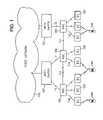
- FIG. 1shows the architecture of such a UMTS network.
- the switches 101 of the communication network belonging to a core network (CN)are linked on the one hand to one or more fixed network 103 and on the other hand, by means of a so-called lu interface, to command equipment 105 or radio network controllers (RNCs).
- RNCsradio network controllers
- Each RNC 105is linked to one or more base stations (BSs) 107 (or Node-Bs according to 3GPP specifications) by means of a so-called lub interface.
- the BSs 107distributed over the territory covered by the network, are capable of communicating by radio with the mobile terminals 109 called user equipments (UEs).
- UEsuser equipments
- Certain RNCs 105may furthermore communicate with one another by means of a so-called lur interface.
- the RNCs 105 and the BSs 107form an access network called UMTS terrestrial radio access network (UTRAN).
- UTRANUMTS terrestrial radio access network
- the UTRANcomprises elements of layers 1 and 2 of the ISO model with a view to providing the links required on the radio interface (called Uu), and a stage 201 ( FIG. 2 ) for controlling the radio resources (radio resource control, RRC) belonging to layer 3, as is described in the 3GPP TS 25.301 technical specification “Radio Interface Protocol Architecture”, version 6.4.0 published in September 2005 by the 3GPP.
- RRCradio resource control
- FIG. 2shows the RRC stages 201 a , 201 b and the stages of the lower layers which belong to the UTRAN and to a UE.
- layer 2is subdivided into a radio link control (RLC) 203 a , 203 b and a medium access control (MAC) stage 205 a , 205 b .
- Layer 1comprises a coding and multiplexing stage 207 a , 207 b .
- a radio stage 209 a , 209 bcaters for the transmission of the radio signals from trains of symbols provided by the stage 207 a , 207 b , and the reception of the signals in the other direction.
- the RRC, RLC and MAC stagesare typically located in the RNC 105 .
- the MAC sublayercan be apportioned among these RNCs 105 , with appropriate protocols for the exchanges on the lur interface, for example asynchronous transfer mode (ATM) and ATM adaptation layer No. 2 (AAL2).
- ATMasynchronous transfer mode
- AAL2ATM adaptation layer No. 2
- HSUPAhigh speed uplink packet access
- E-DCHenhanced dedicated channel
- MAC-es/MAC-ehandles scheduling and MAC-e multiplexing, HARQ retransmissions and E-DCH traffic format combination (TFC) selection.
- the MAC-ehas been introduced in the UTRAN architecture, and more specifically at the BS level to handle HARQ retransmissions, scheduling and MAC-e demultiplexing.
- SRNCserving RNC
- MAC-esis added to provide in-sequence delivery (reordering) and to handle combining of data from different BSs in case of soft handover. This architecture is illustrated in FIG. 3 , and described in the technical specification TS 25.309 “FDD eenhanced uplink; Overall description; Stage 2”, version 6.6.0, published in March 2006 by the 3GPP.
- a resource indication(scheduling grant) is required to indicate to the UE 109 the maximum size of a transport bloc, mapped onto a modulation and coding scheme (MCS) that the UE 109 can use.
- the BS 107may use quality of service (QoS) related information provided by the SNRC and from the UE 109 scheduling requests.
- QoSquality of service
- Absolute grantsprovide an absolute limitation of the maximum amount of uplink resources the UE may use.
- the absolute grantis transmitted in the downlink cell on a physical channel called enhanced absolute grant channel (E-AGCH).
- E-AGCHenhanced absolute grant channel
- One object of the inventionis to limit the above-identified deficiencies.
- a method of adjusting transmission power on a downlink radio channel from a base station to a user equipmentcomprises the following steps carried out at said base station:
- the invention in accordance with an embodiment of the inventionhas the advantage that the transmission power can be adjusted so that the cell capacity and thus the network resources are increased. This also increases the performance of the network and a better quality of service (QoS) can be provided to the users of the network.
- QoSquality of service
- a computer program productcomprising instructions for implementing any of the method steps in accordance with the first aspect of the invention when loaded and run on computer means of the base station.
- a base stationcapable of adjusting transmission power on a downlink radio channel from a base station to a user equipment, said base station comprises:
- FIG. 1is a diagram of a UMTS network to which some embodiments of the invention may be applied;
- FIG. 2is a chart showing the organisation of layers of communication protocols employed on the radio interface of the UMTS network
- FIG. 3illustrates the HSUPA protocol architecture
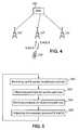
- FIG. 4illustrates how the communication system operates by using the E-DCH and E-AGCH in accordance with embodiments of the invention
- FIG. 5is a flow chart illustrating the power adjustment method in accordance with an embodiment of the invention.
- FIG. 6shows a graphical representation of a relationship between downlink path loss and BS transmit power spectral density to UE power spectral density ratio (I or /I oc );
- FIG. 7shows a graphical representation of a relationship between energy accumulated over one pseudo random chip period after despreading at the BS to BS transmit power spectral density ratio (E o /I or ) and I or /I oc ;
- FIG. 8shows the curves of FIGS. 6 and 7 drawn in the same figure
- FIG. 9is a flow chart depicting a method of detecting errors on E-AGCH in accordance with an embodiment of the invention.
- FIG. 10is a flow chart depicting the power control method in accordance with an embodiment of the invention.
- the considered radio channel between the UE 109 and the BS 107is thus a high speed uplink channel, like an E-DCH.
- the inventioncould also be applied to other channels or units assuming that an uplink power headroom (UPH) or equivalent value is signalled from the UE 109 to the BS 107 .
- UHuplink power headroom
- the inventioncan equally be applied to other types of communication systems as well.
- the network elementsare arranged to implement corresponding protocols shown in FIG. 3 .
- the BSs 107are arranged to transmit on E-AGCH.
- Uplink power headroom(UPH) is determined in the following way:
- UPHP tx , m ⁇ ⁇ ax , UE P tx , DPCCH , UE , ( 1 )
- P tx,max,UEis the maximum transmission power of the UE 109 .
- the UPH valueis signalled (step 501 ) as scheduling information (SI) from the UE 109 to the BS 107 and P tx,DPCCH,UE is the maximum transmission power of the UE 109 on an uplink dedicated physical control channel (DPCCH).
- DIscheduling information
- DPCCHuplink dedicated physical control channel
- the maximum UE 109 transmission poweris signalled by higher layer to layer 1.
- the UE 109can inform the BS 107 about the P tx,max,UE and UPH values and then the BS 107 can calculate the P tx,DPCCH,UE value itself.
- the embodiments of the present inventionuse the UPH value to adjust transmission power of the E-AGCH. This is next explained in more detail. From the radio signal propagation laws it follows:
- PL ULis uplink path loss between the BS 107 and UE 109 and P rx,DPCCH
- UERTWP UL ⁇ SIR UL ⁇ PG
- PGis the processing gain associated to the spreading factor of DPCCH known by the BS 107
- SIR ULis the uplink signal-to-noise ratio measured by the BS 107
- RTWP ULis total received wideband power at the BS 107 .
- the downlink path lossis then calculated in step 505 and a corresponding Ior/Ioc value can be obtained from a chart depicting the relationship between the PLDL and the Ior/Ioc for a specific cell type.
- Ioris the transmit power spectral density at the BS 107 and Ioc is the power spectral density as measured at the UE 109 .
- Ec/Ior value corresponding to the power dedicated to the current channelcan be deduced that has to be applied to reach a target QoS.
- Ecis energy accumulated over one chip period after despreading at the BS 107 .
- the transmission power of the E-AGCHcan be adjusted taking into account the downlink path loss value obtained in step 505 .
- FIG. 6depicts an exemplary relationship between the downlink path loss and the I or /I oc value in a cell located in an urban area.
- the I or /I oc valuesare measured in dBs and then for a certain path loss value, the corresponding I or /I oc value is exceeded with a probability of 95%.
- FIG. 7shows an exemplary relationship between the E c /I or and the I or /I oc . Different curves are obtained for different QoS values. In this example, for instance the received block error rate (BLER) is set to 1%. Such tables can be saved in the BS 107 .
- BLERreceived block error rate
- FIGS. 6 and 7can be drawn in a same figure to better illustrate the relationship between the downlink path loss and the E c /I or .
- the E c /I orindicates the percentage of a transmission power of a certain channel of the total transmission power of the BS 107 .
- the transmission power of the E-AGCHcan be adjusted based on parameters comprising the E c /I or value. In case of grouped scheduling operation (i.e. one E-AGCH is used for several UEs 109 ), the transmission power should be set to the maximum of all UEs 109 individual transmission powers.
- the above power adjustment methodcan be further used as an open loop power control method in communication systems.
- the E c /I or valueis computed every time the BS 107 receives the UPH from the UE 109 .
- the method explained abovecan be modified.
- the faster operation of the E-AGCH power adjustmentis based on the detected errors on the E-AGCH. This is next explained in more detail.
- FIG. 9depicts a flow chart describing the method of detecting errors on the E-AGCH.
- counters of the BS 107are initialised. In this case, there are two counters: a transmission time interval (TTI) counter and an error counter. Entries in the counters are first set to zero. The entries in the TTI counter are set to zero in order to detect any TTIs from the UE 109 .
- TTItransmission time interval
- step 905the BS 107 decodes information transmitted by the UE 109 on E-DPCCH.
- the purpose of decoding the E-DPCCHis here to detect (step 907 ) whether the UE 109 is using an enhanced traffic format combination identifier (E-TFCI) that does not belong to the allowed enhanced traffic format combination (E-TFC) set.
- E-TFCIenhanced traffic format combination identifier
- E-TFCallowed enhanced traffic format combination
- step 907it is detected that the E-TFCI received from the UE 109 does not belong to the E-TFC set defined by the BS 107 , in other words if in this case the used MCS is higher than what was indicated by the BS 107 , then it may be assumed that the UE 109 did not receive information sent on E-AGCH correctly.
- step 909the BS 107 decodes information transmitted on enhanced dedicated physical data channel (E-DPDCH) using the MCS within the allowed E-TFC set that maximises the likelihood of correctly decoding the information transmitted on E-DPCCH.
- E-DPDCHenhanced dedicated physical data channel
- Another E-TFCIis decoded than what was detected in step 907 .
- the purpose of decoding data on E-DPDCHis to determine in step 911 if the data can still be correctly received even if an E-DPCCH decoder does not provide an MCS within the allowed E-TFC set.
- CRCcyclic redundancy check
- step 911If in step 911 it is determined that the CRC of the received data indicates that there are errors in the received data, then in step 913 the error counter is incremented. Then in step 915 the value of the error counter is compared to a predefined maximum error counter value (Counter max ). The purpose of this comparison is to find out whether a certain threshold is exceeded or whether there is just one or few occasional errors that are likely to correspond to E-DPCCH errors on the BS 107 side rather than E-AGCH errors on the UE 109 side.
- Counter maxa predefined maximum error counter value
- step 915If in step 915 it is detected that the maximum number of errors is exceeded, then in step 917 the data that was previously transmitted on E-AGCH is transmitted again and possibly with increased transmission power. The data may be transmitted immediately on the E-AGCH without waiting the regular time interval to elapse. Then in step 919 the error counter is initialised, i.e. the entries of the counter are set to zero. In step 921 an acknowledgement is sent to the UE 109 informing whether the E-DPDCH decoding has been successful or not.
- step 903it is detected that no information is received on E-DPCCH, then it can be concluded that the UE 107 is not transmitting any data and nothing is sent back to UE.
- the error detection procedurethen resumes in step 903 by detecting on E-DPCCH.
- step 907If in step 907 it is detected that the E-TFCI sent by the UE 109 does belong to the E-TFC defined by the BS 107 , i.e. in this case the MCS the UE 109 is using does not exceed the limit set by the BS 107 , then information is decoded in step 923 on E-DPDCH and an acknowledgement is sent in step 921 to the UE 109 informing whether the decoding of the information transmitted on the E-DPDCH has been successfully decoded or not.
- step 911it is determined that the CRC indicates that the received data does not contain an error even if it is assumed that the E-DPCCH decoding provided an E-TFC value that does not belong to the allowed set of E-TFC values, then finally, an acknowledgment is sent in step 921 to the UE 109 informing whether the decoding of the information transmitted on the E-DPDCH has been successful or not.
- the error counteris not initialised and the acknowledgement is sent in step 921 .
- the error detection algorithm described abovemay be so configured that only errors in consecutive data blocks are taken into account.
- the error countersare set to zero, if there are no errors in the subsequently received data blocks.
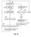
- FIG. 10shows a simplified flow chart of the power adjustment method in accordance with an embodiment of the invention.
- the power calculation based on the UPHis combined with the error detection method described in connection with FIG. 9 .
- step 1001the BS 107 decodes information received on E-DPCCH. Then in step 1003 the BS 107 decodes the scheduling information (SI) and detects that the UE 109 has sent a UPH value. Based on the obtained UPH value, the UE 109 then calculates in step 1005 a suitable transmission power. The UPH value is periodically sent by the UE 109 to the BS 107 in an Si block. The suitable transmission power is calculated as was explained above based on the UPH value. Then in step 1006 the P tx,E-AGCH obtained from the UPH is set to equal to P tx,E-AGCH,new obtained in step 1005 .
- SIscheduling information
- step 1007errors on the E-AGCH are detected.
- the errorscan be detected as was described in the context of FIG. 9 and more specifically in relation to blocks 907 , 909 , 911 and 913 .
- the error counteris initialised in step 1011 and the transmission power adjustment procedure continues in step 1013 by multiplying the current transmission power P tx,E-AGCH by a positive value X (X ⁇ 1). If however, the error counter value does not exceed the maximum value for the counter, then the transmission power adjustment procedure continues in step 1001 by decoding information transmitted on E-DPCCH.
- step 1015the transmission power on the E-AGCH (P tx,E-AGCH ) is compared to a maximum allowed transmission power value P tx,E-AGCH,max on the E-AGCH. In case the calculated P tx,E-AGCH exceeds the maximum value P tx,E-AGCH,max, the transmission power value is set to the P tx,E-AGCH,max. In case the P tx,E-AGCH as calculated is within the limits, then there is no need to change the current transmission power value.
- the BS 107can now send information to the UE 109 on the E-AGCH (step 1017 ).
- a fast open loop power controlwas depicted.
- the inventioncan also be applied to implement fast closed-loop power control.
- the received block error rate (BLER) at the BSneeds to be evaluated.
- p tp E - AGCH ⁇ ( 1 - card ⁇ ( ETFCI ⁇ ⁇ set ) 32 ) , ( 6 ) where p t is a target BLER on E-AGCH, p E-AGCH is a real BLER on E-AGCH and card function chooses the number of elements of the E-TFCI set. The maximum size of the E-TFCI set equals 32. If the MCS signalled on the E-AGCH is set to 32, then any MCS is allowed. In this case there is no way to detect errors on E-AGCH. In reality this is not the case, since in most cases a lower value is chosen for the MCS.
- the transmitted powercan be adjusted according to the following equations:
- Stepis a step function whose value f can be partitioned into a finite number of subintervals on each of which f is a constant.
- the idea of this power control adjustment methodis to set a fixed error probability on E-AGCH and then observe errors on E-AGCH. When an error is detected, the transmission power of the E-AGCH is increased by certain amount and on the other hand if an error is not detected, then the transmission power of the E-AGCH can be reduced by an increment.
- the inventionequally relates to a corresponding software program product which is arranged to implement the method steps described above when loaded and run on computer means of the system.
- the inventionequally relates to a corresponding BS 107 which is arranged to implement at least some of the method steps described above.
Landscapes
- Engineering & Computer Science (AREA)
- Computer Networks & Wireless Communication (AREA)
- Signal Processing (AREA)
- Mobile Radio Communication Systems (AREA)
Abstract
Description
- receiving an uplink power headroom indication from the user equipment;
- obtaining an estimate of an uplink path loss between the user equipment and the base station, said uplink path loss estimate taking account of said uplink power headroom;
- deriving an estimate of a downlink path loss between the user equipment and the base station, from said uplink path loss estimate; and
- adjusting the transmission power on said downlink radio channel by taking account of said downlink path loss estimate.
- means for receiving an uplink power headroom indication from the user equipment;
- means for obtaining an estimate of an uplink path loss between the user equipment and the base station, said uplink path loss estimate taking account of said uplink power headroom;
- means for deriving an estimate of a downlink path loss between the user equipment and the base station, from said uplink path loss estimate; and
- means for adjusting the transmission power on said downlink radio channel by taking account of said downlink path loss estimate.
where Ptx,max,UEis the maximum transmission power of the
Prx,DPCCH,UE=RTWPUL·SIRUL·PG, (3)
where PG is the processing gain associated to the spreading factor of DPCCH known by the
PLDL=Δ·PLUL, (4)
where Δ is a factor taking into account the propagation difference, due to different frequencies used, between the uplink and downlink. Downlink path loss can now be written:
where ptis a target BLER on E-AGCH, pE-AGCHis a real BLER on E-AGCH and card function chooses the number of elements of the E-TFCI set. The maximum size of the E-TFCI set equals 32. If the MCS signalled on the E-AGCH is set to 32, then any MCS is allowed. In this case there is no way to detect errors on E-AGCH. In reality this is not the case, since in most cases a lower value is chosen for the MCS. For instance, if the MCS is set to a value m (m<32), then errors can be detected in the range of (m+1) to 32. Once the E-TFCI set is known, an average number for errors can be estimated using the error detection method described above and finally an estimation for the errors on E-AGCH can be deduced.
where N is the number of observations on E-AGCH during the period, NE-AGCHis the number of observed errors on E-AGCH and n is the TTI index. Step is a step function whose value f can be partitioned into a finite number of subintervals on each of which f is a constant. The idea of this power control adjustment method is to set a fixed error probability on E-AGCH and then observe errors on E-AGCH. When an error is detected, the transmission power of the E-AGCH is increased by certain amount and on the other hand if an error is not detected, then the transmission power of the E-AGCH can be reduced by an increment.
Claims (6)
Priority Applications (3)
| Application Number | Priority Date | Filing Date | Title |
|---|---|---|---|
| US11/545,312US8274952B2 (en) | 2006-10-10 | 2006-10-10 | Transmission power management |
| AT07116063TATE532373T1 (en) | 2006-10-10 | 2007-09-11 | METHOD FOR ADJUSTING THE TRANSMISSION POWER USING THE UPLINK POWER HEADROOM TO CALCULATE THE UPLINK PATH LOSS |
| EP07116063AEP1912345B1 (en) | 2006-10-10 | 2007-09-11 | Method of adjusting transmission power using the uplink power headroom to calculate the uplink path loss |
Applications Claiming Priority (1)
| Application Number | Priority Date | Filing Date | Title |
|---|---|---|---|
| US11/545,312US8274952B2 (en) | 2006-10-10 | 2006-10-10 | Transmission power management |
Publications (2)
| Publication Number | Publication Date |
|---|---|
| US20080084848A1 US20080084848A1 (en) | 2008-04-10 |
| US8274952B2true US8274952B2 (en) | 2012-09-25 |
Family
ID=38828408
Family Applications (1)
| Application Number | Title | Priority Date | Filing Date |
|---|---|---|---|
| US11/545,312Expired - Fee RelatedUS8274952B2 (en) | 2006-10-10 | 2006-10-10 | Transmission power management |
Country Status (3)
| Country | Link |
|---|---|
| US (1) | US8274952B2 (en) |
| EP (1) | EP1912345B1 (en) |
| AT (1) | ATE532373T1 (en) |
Cited By (7)
| Publication number | Priority date | Publication date | Assignee | Title |
|---|---|---|---|---|
| US20080165742A1 (en)* | 2006-12-28 | 2008-07-10 | Interdigital Technology Corporation | Efficient uplink operation with high instantaneous data rates |
| US20110195735A1 (en)* | 2008-08-27 | 2011-08-11 | Ralf Irmer | Multiple Power Control Parameter Sets for Wireless Uplink Data Transmission |
| US20120213149A1 (en)* | 2010-09-21 | 2012-08-23 | Soumen Chakraborty | Method and System for Power Headroom Reporting in the Presence of Multiple Transmit Antennas |
| US20140098799A1 (en)* | 2007-09-21 | 2014-04-10 | Samsung Electronics Co., Ltd. | Apparatus and method for transmitting time interval reconfiguration in a mobile communication system |
| US20140329551A1 (en)* | 2013-05-02 | 2014-11-06 | Samsung Electronics Co., Ltd. | Method and apparatus for controlling uplink power in wireless communication system |
| US9730164B2 (en) | 2012-01-30 | 2017-08-08 | Qualcomm, Incorporated | Power control management in uplink (UL) coordinated multipoint (CoMP) transmission |
| WO2020160247A1 (en)* | 2019-01-31 | 2020-08-06 | Commscope Technologies Llc | Estimating and controlling transmit power of user equipment by a base station |
Families Citing this family (51)
| Publication number | Priority date | Publication date | Assignee | Title |
|---|---|---|---|---|
| US7548506B2 (en) | 2001-10-17 | 2009-06-16 | Nortel Networks Limited | System access and synchronization methods for MIMO OFDM communications systems and physical layer packet and preamble design |
| US8274952B2 (en)* | 2006-10-10 | 2012-09-25 | Alcatel Lucent | Transmission power management |
| GB2447439B (en) | 2007-02-02 | 2012-01-25 | Ubiquisys Ltd | Access point power control |
| US7983687B2 (en)* | 2007-05-11 | 2011-07-19 | Telefonaktiebolaget Lm Ericsson (Publ) | Signal to interference ratio error as a load instability indicator for load control in cellular systems |
| WO2009022812A2 (en)* | 2007-08-10 | 2009-02-19 | Samsung Electronics Co., Ltd. | Apparatus and method for controlling uplink dedicated channel in a mobile communication system |
| WO2009061261A2 (en) | 2007-11-06 | 2009-05-14 | Telefonaktiebolaget L M Ericsson (Publ) | Methods and arrangements in a wireless communication system |
| US20090175187A1 (en)* | 2008-01-07 | 2009-07-09 | Kristina Jersenius | Method and Arrangement for Triggering Power Headroom Report Transmissions in a Telecommunications System |
| KR20090077647A (en)* | 2008-01-11 | 2009-07-15 | 삼성전자주식회사 | Method and apparatus for transmitting available power information of terminal in mobile communication system |
| KR101597377B1 (en)* | 2008-04-28 | 2016-02-25 | 애플 인크. | Method and apparatus for candidate list generation for uplink v-mimo |
| EP2373099A1 (en)* | 2008-04-29 | 2011-10-05 | Telefonaktiebolaget L M Ericsson (Publ) | Distribution of downlink E-DCH power usage |
| WO2010016669A2 (en) | 2008-08-04 | 2010-02-11 | Samsung Electronics Co., Ltd. | Signal transmission method and apparatus for user equipment in mobile communication system |
| WO2010016741A2 (en)* | 2008-08-08 | 2010-02-11 | Samsung Electronics Co., Ltd. | Method and apparatus for dynamically activating and deactivating a supplementary cell for a wcdma system |
| US8670376B2 (en)* | 2008-08-12 | 2014-03-11 | Qualcomm Incorporated | Multi-carrier grant design |
| US8340586B2 (en)* | 2008-11-19 | 2012-12-25 | T-Mobile Usa, Inc. | System and method for link adaptation for variable link conditions |
| TWI542241B (en)* | 2008-12-03 | 2016-07-11 | 內數位專利控股公司 | Method and apparatus for reporting power headroom |
| WO2010085185A1 (en) | 2009-01-20 | 2010-07-29 | Telefonaktiebolaget L M Ericsson (Publ) | Method of estimating path loss for a channel |
| KR101675367B1 (en) | 2009-01-21 | 2016-11-11 | 삼성전자주식회사 | A method for switching mode of transmission in a wireless communication network and a system thereof |
| US8982801B2 (en) | 2009-02-09 | 2015-03-17 | Interdigital Patent Holdings, Inc. | Apparatus and method for uplink power control for a wireless transmitter/receiver unit utilizing multiple carriers |
| EP2634950B1 (en)* | 2009-03-23 | 2016-11-30 | Innovative Sonic Limited | Method and Apparatus for Power Headroom Reporting |
| CN101873657B (en)* | 2009-04-23 | 2014-12-10 | 中兴通讯股份有限公司 | Method for estimating quality of uplink signal in neighboring area and switching and optimizing method |
| US20100272091A1 (en)* | 2009-04-27 | 2010-10-28 | Motorola, Inc. | Uplink Scheduling Supoort in Multi-Carrier Wireless Communication Systems |
| US9084206B2 (en)* | 2009-06-23 | 2015-07-14 | Samsung Electronics Co., Ltd | Method and apparatus for controlling uplink transmission power in wireless communication system |
| EP3570614B1 (en)* | 2009-06-26 | 2020-04-22 | Sun Patent Trust | Radio communication apparatuses and radio communication method |
| GB2471681B (en) | 2009-07-07 | 2011-11-02 | Ubiquisys Ltd | Interference mitigation in a femtocell access point |
| GB2472597B (en) | 2009-08-11 | 2012-05-16 | Ubiquisys Ltd | Power setting |
| EP2465237B1 (en)* | 2009-08-12 | 2020-04-29 | BlackBerry Limited | System and method for modulation and coding scheme adaptation and power control in a relay network |
| CN102577191A (en) | 2009-08-12 | 2012-07-11 | 捷讯研究有限公司 | System and method for association and uplink adaptation in a relay network |
| US9025572B2 (en)* | 2009-09-03 | 2015-05-05 | Via Telecom Co., Ltd. | Apparatus, system, and method for access procedure enhancements |
| EP2806697B1 (en) | 2009-10-01 | 2021-07-28 | Interdigital Patent Holdings, Inc. | Apparatus and Method for Reporting Power Headroom |
| US8254326B2 (en)* | 2009-10-01 | 2012-08-28 | Htc Corporation | Method for transmitting power headroom report and buffer status report in a wireless communication system and related communication device |
| US8909269B2 (en)* | 2009-10-05 | 2014-12-09 | Nokia Siemens Networks Oy | Interference control |
| EP2491750B1 (en)* | 2009-10-23 | 2017-12-06 | Telefonaktiebolaget LM Ericsson (publ) | Methods and arrangements in a communication network system |
| CN101715207B (en)* | 2009-11-04 | 2014-12-31 | 中兴通讯股份有限公司 | Method for measuring power headroom, method for reporting power headroom and terminal |
| CN102685868B (en) | 2009-12-30 | 2014-05-21 | 华为技术有限公司 | A power control method and device |
| CN102271354A (en)* | 2010-06-02 | 2011-12-07 | 中兴通讯股份有限公司 | Link adaptation method for long term evolution (LTE) system, base station and terminal |
| CN101895923B (en)* | 2010-06-11 | 2013-05-08 | 新邮通信设备有限公司 | Power headroom reporting (PHR) method and user equipment in carrier aggregation communication system |
| RU2560922C2 (en) | 2010-06-18 | 2015-08-20 | Телефонактиеболагет Л М Эрикссон (Пабл) | Method for reporting power margin, ordered component carrier indices, and connected wireless terminals and base stations |
| EP2583505B1 (en) | 2010-06-21 | 2019-03-20 | Nokia Solutions and Networks Oy | Carrier aggregation with power headroom report |
| JP5364048B2 (en)* | 2010-07-07 | 2013-12-11 | 株式会社エヌ・ティ・ティ・ドコモ | Base station apparatus and method |
| US8954106B2 (en) | 2010-08-10 | 2015-02-10 | Samsung Electronics Co., Ltd. | Method and apparatus for configuring power headroom information in mobile communication system supporting carrier aggregation |
| KR101881891B1 (en)* | 2010-08-10 | 2018-08-24 | 삼성전자 주식회사 | Method and apparatus for reporting power headroom information in mobile communication for carrier aggregation |
| CN102378239B (en)* | 2010-08-11 | 2015-11-25 | 电信科学技术研究院 | The reporting of power headroom, acquisition methods and device |
| US8737333B2 (en) | 2010-11-08 | 2014-05-27 | Acer Incorporated | Method of power reporting and communication device thereof |
| US9084209B2 (en)* | 2010-11-09 | 2015-07-14 | Qualcomm Incorporated | Carrier grouping for power headroom report |
| US10798684B2 (en) | 2011-09-30 | 2020-10-06 | Interdigital Patent Holdings, Inc. | Multipoint transmission in wireless communication |
| US9392555B2 (en) | 2011-10-06 | 2016-07-12 | Telefonaktiebolaget Lm Ericsson (Publ) | Power controller, method, computer program and computer program product for controlling transmission power |
| CN103167532B (en)* | 2011-12-16 | 2015-09-09 | 鼎桥通信技术有限公司 | The method of subscriber equipment access community and radio network controller |
| US9560603B2 (en)* | 2012-02-29 | 2017-01-31 | Kyocera Corporation | Mobile communication system, mobile communication method, radio base station, and radio terminal |
| CN105191445B (en) | 2013-04-03 | 2018-11-27 | 交互数字专利控股公司 | A kind of interference detecting method, device and base station |
| CN108811070B (en)* | 2017-05-05 | 2023-10-20 | 华为技术有限公司 | Power headroom transmission method and equipment |
| CN109391999B (en)* | 2017-08-08 | 2020-08-18 | 维沃移动通信有限公司 | A PHR reporting method, related equipment and system |
Citations (39)
| Publication number | Priority date | Publication date | Assignee | Title |
|---|---|---|---|---|
| US6134444A (en)* | 1998-03-30 | 2000-10-17 | Motorola, Inc. | Method and apparatus for balancing uplink and downlink transmissions in a communication system |
| US6289217B1 (en)* | 1997-09-17 | 2001-09-11 | Nokia Mobile Phones Ltd. | Adaptive radio link |
| US20010038619A1 (en)* | 2000-04-07 | 2001-11-08 | Philips Corporation | Radio communication system and method of operating the system |
| US20020075939A1 (en)* | 2000-03-22 | 2002-06-20 | Interdigital Technology Corporation | Outer loop/weighted open-loop power control apparatus for a base station |
| US20020077138A1 (en)* | 1999-03-15 | 2002-06-20 | Gunnar Bark | Adaptive power control in a radio communications systems |
| US20020115464A1 (en)* | 2000-11-07 | 2002-08-22 | Samsung Electronics Co., Ltd. | Apparatus and method for transmitting TFCI used for DSCH in a W-CDMA mobile communication system |
| US20020181436A1 (en)* | 2001-04-02 | 2002-12-05 | Jens Mueckenheim | Method and system for UMTS packet transmission scheduling on uplink channels |
| US6584325B1 (en)* | 1999-03-17 | 2003-06-24 | Motorola, Inc. | Subscriber unit and method of cell selection for a cellular communication system |
| US6704579B2 (en)* | 2001-02-15 | 2004-03-09 | Ensemble Communications | System and method of automatically calibrating the gain for a distributed wireless communication system |
| US20040100920A1 (en)* | 2000-06-15 | 2004-05-27 | Carsten Ball | Method for regulating power and for channel allocation in downlink and/or uplink connections of packet data services in a radio communications system, and radio communications system for carrying out said method |
| US20040152481A1 (en)* | 2001-06-01 | 2004-08-05 | Eric Georgeaux | Method for controlling transmission power |
| US6856812B1 (en)* | 2000-06-30 | 2005-02-15 | Lucent Technologies Inc. | Downlink power control method for wireless packet data network |
| US20050036449A1 (en)* | 2003-08-12 | 2005-02-17 | Ranta-Aho Karri | Method and apparatus for implicit TFC reduction and L1 error handling |
| US20050143118A1 (en)* | 2003-11-25 | 2005-06-30 | Bo Bernhardsson | Method and system for determining uplink/downlink path-loss difference |
| US20060035660A1 (en)* | 2004-08-12 | 2006-02-16 | Anderson Nicholas W | Power control in a wireless communication system |
| US20060068830A1 (en)* | 2004-09-30 | 2006-03-30 | Klomsdorf Armin W | Signal configuration based transmitter adjustment in wireless communication devices |
| US20060072503A1 (en)* | 2004-09-30 | 2006-04-06 | Samsung Electronics Co., Ltd. | Method and apparatus for transmitting uplink non-scheduled data in a mobile communication system |
| US7082107B1 (en)* | 2001-11-26 | 2006-07-25 | Intel Corporation | Power control in wireless communications based on estimations of packet error rate |
| US7106694B1 (en)* | 1998-11-06 | 2006-09-12 | Nokia Networks Oy | Method for controlling bearer properties |
| US20060209692A1 (en)* | 2005-02-28 | 2006-09-21 | Ntt Docomo, Inc. | Transmission rate control method, mobile station, and radio network controller |
| US20060252450A1 (en)* | 2005-05-04 | 2006-11-09 | Nokia Corporation | Method, apparatus and computer program providing signaling of configurable power step sizes for high speed uplink packet access (HSUPA) |
| US20060256757A1 (en)* | 2005-04-26 | 2006-11-16 | Markku Kuusela | Method, system, apparatus and software product for combination of uplink dedicated physical control channel gating and enhanced uplink dedicated channel to improve capacity |
| US20060280145A1 (en)* | 2005-06-10 | 2006-12-14 | Revel Agnes M | Event trigger for scheduling information in wireless communication networks |
| US20070002801A1 (en)* | 2005-05-10 | 2007-01-04 | Ntt Docomo, Inc. | Transmission rate control method, mobile station, radio network controller, and radio base station |
| US20070019668A1 (en)* | 2005-07-19 | 2007-01-25 | Samsung Electronics Co., Ltd. | System and method for scheduling uplink in a communication system |
| US20070047501A1 (en)* | 2005-08-24 | 2007-03-01 | Ntt Docomo, Inc. | Transmission power control method, and mobile communication system |
| US7206332B2 (en)* | 2001-06-25 | 2007-04-17 | Nokia Corporation | Optimization of MCS and multi-code with TFCI signaling |
| US20070111746A1 (en)* | 2005-11-16 | 2007-05-17 | Anderson Robert J | Transmit-power control for wireless mobile services |
| US20070115871A1 (en)* | 2005-04-20 | 2007-05-24 | Interdigital Technology Corporation | Method and apparatus for scheduling transmissions via an enhanced dedicated channel |
| US20070149233A1 (en)* | 2005-12-22 | 2007-06-28 | Telefonaktiebolaget Lm Ericsson (Publ) | System and method for determining downlink signaling power in a radio communication network |
| US20080037413A1 (en)* | 2006-08-11 | 2008-02-14 | Samsung Electronics Co., Ltd. | Method and apparatus for uplink scheduling in a mobile communication system |
| US20080039129A1 (en)* | 2004-06-30 | 2008-02-14 | Xiaodong Li | Methods and Apparatus for Power Control in Multi-carier Wireless Systems |
| US7333450B2 (en)* | 1999-06-11 | 2008-02-19 | Nokia Corporation | Power control of network part transmitter in radio system |
| US20080070565A1 (en)* | 2004-11-18 | 2008-03-20 | Masaya Maeda | Method of Setting Radio Channel of Mobile Radio Base-Station |
| US20080084848A1 (en)* | 2006-10-10 | 2008-04-10 | Nortel Networks Limited | Transmission power management |
| US20080102876A1 (en)* | 2004-12-17 | 2008-05-01 | Telefonaktiebolaget Lm Ericsson (Publ) | Power Link Margin for High-Speed Downlink Packet Access |
| US20080175185A1 (en)* | 2006-09-08 | 2008-07-24 | Qualcomm Incorporated | Reverse link feedback for interference control in a wireless communication system |
| US20080254819A1 (en)* | 2005-09-22 | 2008-10-16 | Mitsubishi Electric Corporation | Mobile Station, Fixed Station, Communication System and Communication Method |
| US7656972B2 (en)* | 2001-02-15 | 2010-02-02 | Qualcomm Incorporated | System and method for transmission format detection |
- 2006
- 2006-10-10USUS11/545,312patent/US8274952B2/ennot_activeExpired - Fee Related
- 2007
- 2007-09-11EPEP07116063Apatent/EP1912345B1/ennot_activeNot-in-force
- 2007-09-11ATAT07116063Tpatent/ATE532373T1/enactive
Patent Citations (43)
| Publication number | Priority date | Publication date | Assignee | Title |
|---|---|---|---|---|
| US6289217B1 (en)* | 1997-09-17 | 2001-09-11 | Nokia Mobile Phones Ltd. | Adaptive radio link |
| US6134444A (en)* | 1998-03-30 | 2000-10-17 | Motorola, Inc. | Method and apparatus for balancing uplink and downlink transmissions in a communication system |
| US7106694B1 (en)* | 1998-11-06 | 2006-09-12 | Nokia Networks Oy | Method for controlling bearer properties |
| US20020077138A1 (en)* | 1999-03-15 | 2002-06-20 | Gunnar Bark | Adaptive power control in a radio communications systems |
| US6628956B2 (en)* | 1999-03-15 | 2003-09-30 | Telefonaktiebolaget Lm Ericsson (Publ) | Adaptive power control in a radio communications systems |
| US6584325B1 (en)* | 1999-03-17 | 2003-06-24 | Motorola, Inc. | Subscriber unit and method of cell selection for a cellular communication system |
| US7333450B2 (en)* | 1999-06-11 | 2008-02-19 | Nokia Corporation | Power control of network part transmitter in radio system |
| US20020075939A1 (en)* | 2000-03-22 | 2002-06-20 | Interdigital Technology Corporation | Outer loop/weighted open-loop power control apparatus for a base station |
| US7164660B2 (en)* | 2000-04-07 | 2007-01-16 | Koninklijke Philips Electronics, N.V. | Radio communication system and method of operating the system |
| US20010038619A1 (en)* | 2000-04-07 | 2001-11-08 | Philips Corporation | Radio communication system and method of operating the system |
| US20040100920A1 (en)* | 2000-06-15 | 2004-05-27 | Carsten Ball | Method for regulating power and for channel allocation in downlink and/or uplink connections of packet data services in a radio communications system, and radio communications system for carrying out said method |
| US6856812B1 (en)* | 2000-06-30 | 2005-02-15 | Lucent Technologies Inc. | Downlink power control method for wireless packet data network |
| US20020115464A1 (en)* | 2000-11-07 | 2002-08-22 | Samsung Electronics Co., Ltd. | Apparatus and method for transmitting TFCI used for DSCH in a W-CDMA mobile communication system |
| US7656972B2 (en)* | 2001-02-15 | 2010-02-02 | Qualcomm Incorporated | System and method for transmission format detection |
| US6704579B2 (en)* | 2001-02-15 | 2004-03-09 | Ensemble Communications | System and method of automatically calibrating the gain for a distributed wireless communication system |
| US20020181436A1 (en)* | 2001-04-02 | 2002-12-05 | Jens Mueckenheim | Method and system for UMTS packet transmission scheduling on uplink channels |
| US20040152481A1 (en)* | 2001-06-01 | 2004-08-05 | Eric Georgeaux | Method for controlling transmission power |
| US7206332B2 (en)* | 2001-06-25 | 2007-04-17 | Nokia Corporation | Optimization of MCS and multi-code with TFCI signaling |
| US7082107B1 (en)* | 2001-11-26 | 2006-07-25 | Intel Corporation | Power control in wireless communications based on estimations of packet error rate |
| US20050036449A1 (en)* | 2003-08-12 | 2005-02-17 | Ranta-Aho Karri | Method and apparatus for implicit TFC reduction and L1 error handling |
| US7302276B2 (en)* | 2003-11-25 | 2007-11-27 | Telefonaktiebolaget L M Ericsson (Publ) | Method and system for determining uplink/downlink path-loss difference |
| US20050143118A1 (en)* | 2003-11-25 | 2005-06-30 | Bo Bernhardsson | Method and system for determining uplink/downlink path-loss difference |
| US20080039129A1 (en)* | 2004-06-30 | 2008-02-14 | Xiaodong Li | Methods and Apparatus for Power Control in Multi-carier Wireless Systems |
| US20060035660A1 (en)* | 2004-08-12 | 2006-02-16 | Anderson Nicholas W | Power control in a wireless communication system |
| US20060072503A1 (en)* | 2004-09-30 | 2006-04-06 | Samsung Electronics Co., Ltd. | Method and apparatus for transmitting uplink non-scheduled data in a mobile communication system |
| US20060068830A1 (en)* | 2004-09-30 | 2006-03-30 | Klomsdorf Armin W | Signal configuration based transmitter adjustment in wireless communication devices |
| US20080070565A1 (en)* | 2004-11-18 | 2008-03-20 | Masaya Maeda | Method of Setting Radio Channel of Mobile Radio Base-Station |
| US20080102876A1 (en)* | 2004-12-17 | 2008-05-01 | Telefonaktiebolaget Lm Ericsson (Publ) | Power Link Margin for High-Speed Downlink Packet Access |
| US20060209692A1 (en)* | 2005-02-28 | 2006-09-21 | Ntt Docomo, Inc. | Transmission rate control method, mobile station, and radio network controller |
| US20070115871A1 (en)* | 2005-04-20 | 2007-05-24 | Interdigital Technology Corporation | Method and apparatus for scheduling transmissions via an enhanced dedicated channel |
| US7408895B2 (en)* | 2005-04-20 | 2008-08-05 | Interdigital Technology Corporation | Method and apparatus for scheduling transmissions via an enhanced dedicated channel |
| US20060256757A1 (en)* | 2005-04-26 | 2006-11-16 | Markku Kuusela | Method, system, apparatus and software product for combination of uplink dedicated physical control channel gating and enhanced uplink dedicated channel to improve capacity |
| US20060252450A1 (en)* | 2005-05-04 | 2006-11-09 | Nokia Corporation | Method, apparatus and computer program providing signaling of configurable power step sizes for high speed uplink packet access (HSUPA) |
| US20070002801A1 (en)* | 2005-05-10 | 2007-01-04 | Ntt Docomo, Inc. | Transmission rate control method, mobile station, radio network controller, and radio base station |
| US20060280145A1 (en)* | 2005-06-10 | 2006-12-14 | Revel Agnes M | Event trigger for scheduling information in wireless communication networks |
| US20070019668A1 (en)* | 2005-07-19 | 2007-01-25 | Samsung Electronics Co., Ltd. | System and method for scheduling uplink in a communication system |
| US20070047501A1 (en)* | 2005-08-24 | 2007-03-01 | Ntt Docomo, Inc. | Transmission power control method, and mobile communication system |
| US20080254819A1 (en)* | 2005-09-22 | 2008-10-16 | Mitsubishi Electric Corporation | Mobile Station, Fixed Station, Communication System and Communication Method |
| US20070111746A1 (en)* | 2005-11-16 | 2007-05-17 | Anderson Robert J | Transmit-power control for wireless mobile services |
| US20070149233A1 (en)* | 2005-12-22 | 2007-06-28 | Telefonaktiebolaget Lm Ericsson (Publ) | System and method for determining downlink signaling power in a radio communication network |
| US20080037413A1 (en)* | 2006-08-11 | 2008-02-14 | Samsung Electronics Co., Ltd. | Method and apparatus for uplink scheduling in a mobile communication system |
| US20080175185A1 (en)* | 2006-09-08 | 2008-07-24 | Qualcomm Incorporated | Reverse link feedback for interference control in a wireless communication system |
| US20080084848A1 (en)* | 2006-10-10 | 2008-04-10 | Nortel Networks Limited | Transmission power management |
Non-Patent Citations (2)
| Title |
|---|
| Technical Specification, "3GPP TS 25.309 V6 6.0 (Mar. 2006); 3rd Generation Partnership Project; Technical Specification Group Radion Access Network; FDD Enhanced Uplink; Overall Description; Stage 2, Release 6"; Mar. 2006.* |
| TS 25.309, V6.6.0, "FDD Enhanced Uplink; Overall description; Stage 2 (Release 6)", published in Mar. 2006 by the 3GPP.* |
Cited By (23)
| Publication number | Priority date | Publication date | Assignee | Title |
|---|---|---|---|---|
| US8824419B2 (en)* | 2006-12-28 | 2014-09-02 | Interdigital Technology Corporation | Efficient uplink operation with high instantaneous data rates |
| US20080165742A1 (en)* | 2006-12-28 | 2008-07-10 | Interdigital Technology Corporation | Efficient uplink operation with high instantaneous data rates |
| US20140098799A1 (en)* | 2007-09-21 | 2014-04-10 | Samsung Electronics Co., Ltd. | Apparatus and method for transmitting time interval reconfiguration in a mobile communication system |
| US9385841B2 (en)* | 2007-09-21 | 2016-07-05 | Samsung Electronics Co., Ltd | Apparatus and method for transmission time interval reconfiguration in a mobile communication system |
| US20110195735A1 (en)* | 2008-08-27 | 2011-08-11 | Ralf Irmer | Multiple Power Control Parameter Sets for Wireless Uplink Data Transmission |
| US20120213149A1 (en)* | 2010-09-21 | 2012-08-23 | Soumen Chakraborty | Method and System for Power Headroom Reporting in the Presence of Multiple Transmit Antennas |
| US9173178B2 (en)* | 2010-09-21 | 2015-10-27 | Broadcom Corporation | Method and system for power headroom reporting in the presence of multiple transmit antennas |
| US9730164B2 (en) | 2012-01-30 | 2017-08-08 | Qualcomm, Incorporated | Power control management in uplink (UL) coordinated multipoint (CoMP) transmission |
| US11076361B2 (en) | 2012-01-30 | 2021-07-27 | Qualcomm Incorporated | Power control management in uplink (UL) coordinated multipoint (CoMP) transmission |
| US10674453B2 (en) | 2012-01-30 | 2020-06-02 | Qualcomm Incorporated | Power control management in uplink (UL) coordinated multipoint (CoMP) transmission |
| US20140329551A1 (en)* | 2013-05-02 | 2014-11-06 | Samsung Electronics Co., Ltd. | Method and apparatus for controlling uplink power in wireless communication system |
| US10142940B2 (en)* | 2013-05-02 | 2018-11-27 | Samsung Electronics Co., Ltd. | Method and apparatus for controlling uplink power in wireless communication system |
| US20190028976A1 (en)* | 2013-05-02 | 2019-01-24 | Samsung Electronics Co., Ltd. | Method and apparatus for controlling uplink power in wireless communication system |
| US10531396B2 (en)* | 2013-05-02 | 2020-01-07 | Samsung Electronics Co., Ltd. | Method and apparatus for controlling uplink power in wireless communication system |
| US20170164298A1 (en)* | 2013-05-02 | 2017-06-08 | Samsung Electronics Co., Ltd. | Method and apparatus for controlling uplink power in wireless communication system |
| US10834682B2 (en)* | 2013-05-02 | 2020-11-10 | Samsung Electronics Co., Ltd. | Method and apparatus for controlling uplink power in wireless communication system |
| US9603098B2 (en)* | 2013-05-02 | 2017-03-21 | Samsung Electronics Co., Ltd. | Method and apparatus for controlling uplink power in wireless communication system |
| US11564175B2 (en)* | 2013-05-02 | 2023-01-24 | Samsung Electronics Co., Ltd. | Method and apparatus for controlling uplink power in wireless communication system |
| US11785554B2 (en) | 2013-05-02 | 2023-10-10 | Samsung Electronics Co., Ltd. | Method and apparatus for controlling uplink power in wireless communication system |
| US20240040512A1 (en)* | 2013-05-02 | 2024-02-01 | Samsung Electronics Co., Ltd. | Method and apparatus for controlling uplink power in wireless communication system |
| US12267786B2 (en)* | 2013-05-02 | 2025-04-01 | Samsung Electronics Co., Ltd. | Method and apparatus for controlling uplink power in wireless communication system |
| WO2020160247A1 (en)* | 2019-01-31 | 2020-08-06 | Commscope Technologies Llc | Estimating and controlling transmit power of user equipment by a base station |
| US11716694B2 (en) | 2019-01-31 | 2023-08-01 | Commscope Technologies Llc | Estimating and controlling transmit power of user equipment by a base station |
Also Published As
| Publication number | Publication date |
|---|---|
| US20080084848A1 (en) | 2008-04-10 |
| EP1912345B1 (en) | 2011-11-02 |
| ATE532373T1 (en) | 2011-11-15 |
| EP1912345A1 (en) | 2008-04-16 |
Similar Documents
| Publication | Publication Date | Title |
|---|---|---|
| US8274952B2 (en) | Transmission power management | |
| US12127262B2 (en) | Wireless communication system and method of controlling a transmission power | |
| EP1741207B1 (en) | Method and apparatus for channel sensitive scheduling in a communication system | |
| JP5265502B2 (en) | Method and system for data transmission in a communication system | |
| JP4737553B2 (en) | Wireless communication system, mobile station, base station, wireless communication system control method used therefor, and program thereof | |
| KR100828800B1 (en) | Hybrid tdm/ofdm/cdm reverse link transmission | |
| US20040252670A1 (en) | Adaptive power margin adjustment for a 1xEV-DV system | |
| EP1724978A2 (en) | Radio resource control in HSUPA system | |
| EP1594267A2 (en) | Method and apparatus for setting power for transmitting signaling information on an e-dch | |
| JPWO2007043098A1 (en) | Mobile station and communication method | |
| US20110038342A1 (en) | Distribution of downlink e-dch power usage | |
| JP4850296B2 (en) | Base station and transmission control method | |
| US20060236190A1 (en) | Power control of packet data transmission in cellular network | |
| US7376426B2 (en) | Memory management in mobile network | |
| CN100550679C (en) | HSUPA exterior ring power control implementation method | |
| WO2006031187A1 (en) | Method and arrangement in a telecommunication system | |
| Toskala et al. | High‐Speed Downlink Packet Access | |
| WO2005117363A1 (en) | Method and arrangement for uplink scheduling |
Legal Events
| Date | Code | Title | Description |
|---|---|---|---|
| AS | Assignment | Owner name:NORTEL NETWORKS LIMITED, CANADA Free format text:ASSIGNMENT OF ASSIGNORS INTEREST;ASSIGNORS:JARD, ALEXANDRE;CORBEL, JEAN-MARC;MORETTE, MICHAEL;REEL/FRAME:018872/0373;SIGNING DATES FROM 20061208 TO 20061211 Owner name:NORTEL NETWORKS LIMITED, CANADA Free format text:ASSIGNMENT OF ASSIGNORS INTEREST;ASSIGNORS:JARD, ALEXANDRE;CORBEL, JEAN-MARC;MORETTE, MICHAEL;SIGNING DATES FROM 20061208 TO 20061211;REEL/FRAME:018872/0373 | |
| AS | Assignment | Owner name:ALCATEL LUCENT, FRANCE Free format text:ASSIGNMENT OF ASSIGNORS INTEREST;ASSIGNOR:NORTEL NETWORKS LIMITED;REEL/FRAME:020947/0899 Effective date:20080513 | |
| AS | Assignment | Owner name:ROCKSTAR BIDCO, LP, NEW YORK Free format text:ASSIGNMENT OF ASSIGNORS INTEREST;ASSIGNOR:NORTEL NETWORKS LIMITED;REEL/FRAME:027143/0717 Effective date:20110729 | |
| FEPP | Fee payment procedure | Free format text:PAYOR NUMBER ASSIGNED (ORIGINAL EVENT CODE: ASPN); ENTITY STATUS OF PATENT OWNER: LARGE ENTITY | |
| STCF | Information on status: patent grant | Free format text:PATENTED CASE | |
| FPAY | Fee payment | Year of fee payment:4 | |
| FEPP | Fee payment procedure | Free format text:MAINTENANCE FEE REMINDER MAILED (ORIGINAL EVENT CODE: REM.); ENTITY STATUS OF PATENT OWNER: LARGE ENTITY | |
| LAPS | Lapse for failure to pay maintenance fees | Free format text:PATENT EXPIRED FOR FAILURE TO PAY MAINTENANCE FEES (ORIGINAL EVENT CODE: EXP.); ENTITY STATUS OF PATENT OWNER: LARGE ENTITY | |
| STCH | Information on status: patent discontinuation | Free format text:PATENT EXPIRED DUE TO NONPAYMENT OF MAINTENANCE FEES UNDER 37 CFR 1.362 | |
| FP | Lapsed due to failure to pay maintenance fee | Effective date:20200925 |