US8274289B2 - Antenna coupling component measurement tool having rotating antenna configuration - Google Patents
Antenna coupling component measurement tool having rotating antenna configurationDownload PDFInfo
- Publication number
- US8274289B2 US8274289B2US12/294,557US29455706AUS8274289B2US 8274289 B2US8274289 B2US 8274289B2US 29455706 AUS29455706 AUS 29455706AUS 8274289 B2US8274289 B2US 8274289B2
- Authority
- US
- United States
- Prior art keywords
- tool
- receiver
- transmitter
- antenna
- measurements
- Prior art date
- Legal status (The legal status is an assumption and is not a legal conclusion. Google has not performed a legal analysis and makes no representation as to the accuracy of the status listed.)
- Active, expires
Links
- 238000005259measurementMethods0.000titleclaimsabstractdescription66
- 230000008878couplingEffects0.000titleclaimsabstractdescription28
- 238000010168coupling processMethods0.000titleclaimsabstractdescription28
- 238000005859coupling reactionMethods0.000titleclaimsabstractdescription28
- 230000015572biosynthetic processEffects0.000claimsabstractdescription53
- 239000011159matrix materialSubstances0.000claimsabstractdescription24
- 230000004044responseEffects0.000claimsdescription13
- 238000000034methodMethods0.000abstractdescription17
- 238000012935AveragingMethods0.000abstract1
- 238000005755formation reactionMethods0.000description48
- 238000005553drillingMethods0.000description12
- 230000010363phase shiftEffects0.000description10
- 230000008569processEffects0.000description8
- 238000006880cross-coupling reactionMethods0.000description7
- 238000007598dipping methodMethods0.000description5
- 238000010304firingMethods0.000description5
- 238000012545processingMethods0.000description5
- XQCFHQBGMWUEMY-ZPUQHVIOSA-NNitrovinChemical compoundC=1C=C([N+]([O-])=O)OC=1\C=C\C(=NNC(=N)N)\C=C\C1=CC=C([N+]([O-])=O)O1XQCFHQBGMWUEMY-ZPUQHVIOSA-N0.000description4
- 238000012986modificationMethods0.000description4
- 230000004048modificationEffects0.000description4
- 238000010586diagramMethods0.000description3
- 238000013500data storageMethods0.000description2
- 239000012530fluidSubstances0.000description2
- 230000006698inductionEffects0.000description2
- 239000000463materialSubstances0.000description2
- 239000004215Carbon black (E152)Substances0.000description1
- 239000004593EpoxySubstances0.000description1
- 238000004364calculation methodMethods0.000description1
- 239000000919ceramicSubstances0.000description1
- 239000011231conductive fillerSubstances0.000description1
- 239000004020conductorSubstances0.000description1
- 238000005520cutting processMethods0.000description1
- 238000013461designMethods0.000description1
- 238000001514detection methodMethods0.000description1
- 230000000694effectsEffects0.000description1
- 229930195733hydrocarbonNatural products0.000description1
- 125000001183hydrocarbyl groupChemical group0.000description1
- 238000003384imaging methodMethods0.000description1
- 230000014759maintenance of locationEffects0.000description1
- 230000035515penetrationEffects0.000description1
- 239000003208petroleumSubstances0.000description1
- 238000011084recoveryMethods0.000description1
- 230000000717retained effectEffects0.000description1
- 239000005060rubberSubstances0.000description1
- 230000003068static effectEffects0.000description1
- 238000012360testing methodMethods0.000description1
- 238000012546transferMethods0.000description1
- 230000032258transportEffects0.000description1
Images


Classifications
- G—PHYSICS
- G01—MEASURING; TESTING
- G01V—GEOPHYSICS; GRAVITATIONAL MEASUREMENTS; DETECTING MASSES OR OBJECTS; TAGS
- G01V3/00—Electric or magnetic prospecting or detecting; Measuring magnetic field characteristics of the earth, e.g. declination, deviation
- G01V3/18—Electric or magnetic prospecting or detecting; Measuring magnetic field characteristics of the earth, e.g. declination, deviation specially adapted for well-logging
- G01V3/26—Electric or magnetic prospecting or detecting; Measuring magnetic field characteristics of the earth, e.g. declination, deviation specially adapted for well-logging operating with magnetic or electric fields produced or modified either by the surrounding earth formation or by the detecting device
- G01V3/28—Electric or magnetic prospecting or detecting; Measuring magnetic field characteristics of the earth, e.g. declination, deviation specially adapted for well-logging operating with magnetic or electric fields produced or modified either by the surrounding earth formation or by the detecting device using induction coils
- E—FIXED CONSTRUCTIONS
- E21—EARTH OR ROCK DRILLING; MINING
- E21B—EARTH OR ROCK DRILLING; OBTAINING OIL, GAS, WATER, SOLUBLE OR MELTABLE MATERIALS OR A SLURRY OF MINERALS FROM WELLS
- E21B47/00—Survey of boreholes or wells
- E21B47/02—Determining slope or direction
- E21B47/024—Determining slope or direction of devices in the borehole
- G—PHYSICS
- G01—MEASURING; TESTING
- G01B—MEASURING LENGTH, THICKNESS OR SIMILAR LINEAR DIMENSIONS; MEASURING ANGLES; MEASURING AREAS; MEASURING IRREGULARITIES OF SURFACES OR CONTOURS
- G01B7/00—Measuring arrangements characterised by the use of electric or magnetic techniques
- G01B7/30—Measuring arrangements characterised by the use of electric or magnetic techniques for measuring angles or tapers; for testing the alignment of axes
- G—PHYSICS
- G01—MEASURING; TESTING
- G01V—GEOPHYSICS; GRAVITATIONAL MEASUREMENTS; DETECTING MASSES OR OBJECTS; TAGS
- G01V3/00—Electric or magnetic prospecting or detecting; Measuring magnetic field characteristics of the earth, e.g. declination, deviation
- G01V3/18—Electric or magnetic prospecting or detecting; Measuring magnetic field characteristics of the earth, e.g. declination, deviation specially adapted for well-logging
- G01V3/34—Transmitting data to recording or processing apparatus; Recording data
Definitions
- induction loggingto determine the resistivity (or its inverse, conductivity) of earth formations adjacent a borehole has long been a standard and important technique in the search for and recovery of subterranean petroleum deposits.
- a transmittertransmits an electromagnetic signal that passes through formation materials around the borehole and induces a signal in ore or more receivers.
- the amplitude and/or phase of the receiver signalsare influenced by the formation resistivity, enabling resistivity measurements to be made.
- the measured signal characteristics and/or formation properties calculated therefromare recorded as a function of the tool's depth or position in the borehole, yielding a formation log that can be used by analysts.
- the resistivity of a given formationmay be isotropic (equal in all directions) or anisotropic (unequal in different directions).
- the anisotropyis generally attributable to extremely fine layering during the sedimentary build-up of the formation.
- resistivities R X and R Y in directions x and y, respectivelytend to be the same, but resistivity R Z in the z direction is different.
- the resistivity in a direction parallel to the plane of the formationi.e., the x-y plane
- the resistivity in the direction perpendicular to the plane of the formationi.e., the z direction
- boreholesare generally not perpendicular to formation beds.
- the angle between the axis of the well bore and the orientation of the formation beds(as represented by the normal vector) has two components. These components are the dip angle and the strike angle.
- the dip angleis the angle between the borehole axis and the normal vector for the formation bed.
- the strike angleis the direction in which the boreholes axis “leans away from” the normal vector. (These will be defined more rigorously in the detailed description.)
- Electromagnetic resistivity logging measurementsare a complex function of formation resistivity, formation anisotropy, and the formation dip and strike angles, which may all be unknown. Logging tools that fail to account for one or more of these parameters may provide measurement quality that is less than ideal. Conversely, tools that can be used to measure each of these parameters will provide improved resistivity measurements. Moreover, tools that are able to provide dip and strike measurements along with azimuthal orientation information, can be used for geosteering. (Geosteering is a process in which drill engineers adjust the drilling direction to increase the borehole's exposure to a hydrocarbon-bearing formation (the “payzone”).)
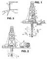
- FIG. 1shows an illustrative logging while drilling environment including dipping formation beds
- FIG. 2shows an illustrative wireline logging environment including dipping formation beds
- FIG. 3shows a relationship between the orientation of a borehole and a dipping formation bed
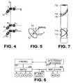
- FIG. 4shows a hypothetical antenna arrangement for a tool having an orthogonal triaxial transmitter and two orthogonal triaxial receivers
- FIG. 5shows angles for defining the orientation of a tilted antenna
- FIG. 6is a block diagram of an illustrative electronics module for an electromagnetic resistivity tool
- FIG. 8is a flow diagram of an illustrative electromagnetic resistivity logging method
- FIG. 9shows an illustrative electromagnetic resistivity logging tool having parallel tilted transmitter and receiver antennas
- FIG. 10shows an illustrative electromagnetic resistivity logging tool having transmitters tilted at a first orientation and receiver antennas tilted at a second orientation
- FIG. 11shows an illustrative electromagnetic resistivity logging tool having both parallel and non-parallel tilted transmitter and receiver antennas
- FIG. 12shows an illustrative electromagnetic resistivity logging tool having co-located tilted receiver antennas
- FIG. 13shows the division of a borehore circumference into azimuthal bins
- FIG. 14shows an illustrative electromagnetic resistivity logging tool having compensated measurements.
- Electrodesthat employ rotation of an azimuthally sensitive antenna configuration to obtain more elements of a coupling matrix than could be obtained from the static antenna configuration alone.
- Such exploitation of the rotationenables a complete antenna coupling matrix to be obtained with a tool having only two antenna orientations.
- the various resistivity measurement parameterscan be measured, including formation resistivity, formation anisotropy, and formation dip and strike angles.
- the coupling matrix valuesare combined with orientation information from the tool, geosteering or boundary detection signals may be derived. Such benefits may be obtained with a reduced cost and greater reliability due to the reduced number of antennas.
- FIG. 1An illustrative logging while drilling (LWD) environment is shown in FIG. 1 .
- a drilling platform 2supports a derrick 4 having a traveling block 6 for raising and lowering a drill string 8 .
- a kelly 10supports the drill string 8 as it is lowered through a rotary table 12 .
- a drill bit 14is driven by a downhole motor and/or rotation of the drill string 8 . As bit 14 rotates, it creates a borehole 16 that passes through various formations 18 .
- a pump 20circulates drilling fluid through a feed pipe 22 to kelly 10 , downhole through the interior of drill string 8 , through orifices in drill bit 14 , back to the surface via the annulus around drill string 8 , and into a retention pit 24 .
- the drilling fluidtransports cuttings from the borehole into the pit 24 and aids in maintaining the borehole integrity.
- An electromagnetic resistivity logging tool 26is integrated into the bottom-hole assembly near the bit 14 .
- logging tool 26collects measurements relating to various formation properties as well as the tool orientation and position and various other drilling conditions.
- the orientation measurementsmay be performed using an azimuthal orientation indicator, which may include magnetometers, inclinometers, and/or accelerometers, though other sensor types such as gyroscopes may be used.
- the toolincludes a 3-axis fluxgate magnetometer and a 3-axis accelerometer.
- the logging tool 26may take the form of a drill collar, i.e., a thick-walled tubular that provides weight and rigidity to aid the drilling process.
- a telemetry sub 28may be included to transfer tool measurements to a surface receiver 30 and to receive commands from the surface receiver.
- rotational position indicator 70may contain both a 3-axis fluxgate magnetometer and a 3-axis accelerometer.
- the combination of those two sensor systemsenables the measurement of the toolface, inclination, and azimuth orientation angles of the borehole.
- the toolface and hole inclination anglesare calculated from the accelerometer sensor output.
- the magnetometer sensor outputsare used to calculate the hole azimuth.
- a tool in accordance with the present inventioncan be used to steer the bit to the desirable bed.
- the response difference or the response ratiocan be used effectively to enter a desired payzone or to stay within the payzone of interest.
- the drill string 8may be removed from the borehole as shown in FIG. 2 .
- logging operationscan be conducted using a wireline logging tool 34 , i.e., a sensing instrument sonde suspended by a cable 42 having conductors for transporting power to the tool and telemetry from the tool to the surface.
- a resistivity imaging portion of the logging tool 34may have centralizing arms 36 that center the tool within the borehole as the tool is pulled uphole.
- a logging facility 44collects measurements from the logging tool 34 , and includes computing facilities for processing and storing the measurements gathered by the logging tool.
- FIG. 1shows that the formations 18 are not perpendicular to the borehole, which may occur naturally or due to directional drilling operations.
- the boreholemay have a coordinate system 50 defined in accordance with the borehole's long axis (the z axis) and the north side (or alternatively, the high side) of the hole (the x-axis).
- the formations 18when characterized as a plane, may have a coordinate system 51 defined in accordance with the normal to the plane (the z′′ axis) and the direction of steepest descent (the x-axis). As shown in FIG. 3 , the two coordinate systems are related by two rotations.
- a first rotation of angle ⁇is made about the z axis.
- the resulting coordinate systemis denoted (x′,y′,z′).
- Angle ⁇is the relative strike angle, which indicates the direction of the formation dip relative to the borehole's coordinate system.
- a second rotation of angle ⁇is then made about the y′ axis. This aligns the borehole coordinate system with the formation coordinate system.
- Angle ⁇is the relative dip angle, which is the slope angle of the beds relative to the long axis of the borehole.
- the vertical resistivityis generally found to be the resistivity as measured perpendicular to the plane of the formation
- the horizontal resistivityis the resistivity as measured within the plane of the formation. Determination of each of these parameters (dip angle, strike angle, vertical resistivity, and horizontal resistivity) is desirable.
- FIG. 4shows a hypothetical antenna configuration for a multi-component electromagnetic resistivity logging tool.
- the electromagnetic resistivity logging toolmay be embodied as a wireline tool and as a logging while drilling tool.
- a triad of transmitter coils T X , T Y and T Zeach oriented along a respective axis, is provided.
- At least one triad of similarly oriented receiver coils R 1X , R 1Y , and R 1Zis also provided.
- For receive signal measurements relative to the amplitude and phase of the transmit signal(sometimes called “absolute” measurements), only one receiver triad would be used.
- a second triad of similarly oriented receiver coils pairs R 2X , R 2Y , and R 2Zmay also provided when differential measurements are desired (e.g., a signal amplitude ratio or a phase difference between receiver coils oriented along a given axis). Differential measurements may offer increased spatial resolution.
- Equation (1)is:
- [ H x H y H z ][ C xx C xy C xz C yx C yy C zz C zx C zy C zz ] ⁇ [ M x M y M z ] , ( 2 )
- M X , M Y , and M Zare the magnetic moments (proportional to transmit signal strength) created by transmitters T X , T Y , and T Z , respectively.
- H X , H Y , H Zare the magnetic fields (proportional to receive signal strength) at the receiver antennas R X , R Y , and R Z , respectively.
- C IJa IJ V I J , where I is the index for receiver R X , R Y , or R Z , J is the index for transmitter T X , T Y , or T Z , a IJ is a constant determined by the tool design, and V I J is a complex value representing the signal amplitude and phase shift measured by receiver I in response to the firing of transmitter J.
- Knowledge of the complete coupling matrixenables the determination of dip angle, strike angle, vertical resistivity, and horizontal resistivity.
- dip and strike anglemay be determined from coupling matrix values as explained by Li Gao and Stanley Gianzero, U.S. Pat. No. 6,727,706 “Virtual Steering of Induction Tool for Determination of Formation Dip Angle”. Given these angles, vertical and horizontal resistivity can be determined in accordance with equations provided by Michael Bittar, U.S. Pat. No. 7,019,528 “Electromagnetic Wave Resistivity Tool Having a Tilted Antenna for Geosteering within a Desired Payzone”. Alternatively, a simultaneous solution for these parameters may be found as described in the Bittar reference.
- FIG. 5shows two angles that may be used to specify the orientation of a coil antenna.
- the coil antennamay be considered as residing in a plane having a normal vector.
- Tilt angle ⁇is the angle between the longitudinal axis of the tool and the normal vector.
- Azimuth angle ⁇is the angle between the projection of the normal vector in the X-Y plane and the tool scribe line.
- azimuthal angle ⁇may represent the angle between projection of the normal vector in the X-Y plane and the x-axis of the borehole coordinate system.
- FIG. 6shows a functional block diagram of the electronics for a resistivity tool.
- the electronicsinclude a control module 602 that is coupled to an analog switch 604 .
- Analog switch 604is configured to drive any one of the transmitter coils T 1 , T 2 , T 3 , T 4 with an alternating current (AC) signal from a signal source 606 .
- the signal sourceprovides radio frequency signals.
- the control module 602preferably selects a transmitter coil, pauses long enough for transients to die out, then signals data storage/transmit module 610 to accept an amplitude and phase sample of the signals received by each of the receivers.
- the control module 602preferably repeats this process sequentially for each of the transmitters.
- the amplitude and phase shift valuesare provided by amplitude and phase shift detector 608 which is coupled to each of the receiver coils R 1 and R 2 for this purpose.
- Control module 602may process the amplitude and phase shift measurements to obtain compensated measurements and/or measurement averages.
- the raw, compensated, or averaged measurementsmay be transmitted to the surface for processing to determine dip and strike angles, vertical and horizontal resistivity, and other information such as (i) distance to nearest bed boundary, (ii) direction of nearest bed boundary, and (iii) resistivity of any nearby adjacent beds.
- the data storage/transmitter module 610may be coupled to telemetry unit 28 ( FIG. 1 ) to transmit signal measurements to the surface. Telemetry unit 28 can use any of several known techniques for transmitting information to the surface, including but not limited to (1) mud pressure pulse; (2) hard-wire connection; (3) acoustic wave; and (4) electromagnetic waves.
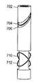
- FIG. 7shows an electromagnetic resistivity logging tool 702 having only two receiver antenna orientations.
- the tool 702is provided with one or more regions 706 of reduced diameter.
- a wire coil 704is placed in the region 706 and in some embodiments is spaced away from the surface of subassembly 702 by a constant distance.
- a non-conductive filler materialsuch as epoxy, rubber, or ceramic may be used in the reduced diameter regions 706 .
- Coil 704is a transmitter coil, and coils 710 and 712 are receiving coils. In operation, transmitter coil 704 transmits an interrogating electromagnetic signal which propagates through the borehole and surrounding formation.
- Receiver coils 710 , 712detect the interrogating electromagnetic signal and provide a measure of the electromagnetic signal's amplitude attenuation and phase shift. For differential measurements additional receiver coils parallel to coils 710 , 712 may be provided at an axially-spaced distance. From the absolute or differential amplitude attenuation and phase shift measurements, the coupling matrix components can be determined and used as the basis for determining formation parameters and as the basis for geosteering.
- the transmitter coil 704may be spaced approximately 30 inches from the receiver coils 710 , 712 .
- the transmitter and receiver coilsmay comprise as little as one loop of wire, although more loops may provide additional signal power.
- the distance between the coils and the tool surfaceis preferably in the range from 1/16 inch to 3 ⁇ 4 inch, but may be larger.
- Transmitter coil 704 and receiver coil 712may each have a tilt angle of about 45° and aligned with the same azimuth angle, while receiver coil 710 may have a tilt angle of about 45° and an azimuth 180° apart from receiver coil 712 (or equivalently, a tilt angle of minus 45° at the same azimuth angle as receiver coil 712 ).
- the signal measured by a tilted receiver in response to the firing of a tilted transmittercan be expressed in terms of the signals V I Y that would be measured by the tool of FIG. 4 .
- the tilted receiver signal V Ris
- V R[ sin ⁇ ⁇ ⁇ T ⁇ cos ⁇ ⁇ ⁇ sin ⁇ ⁇ ⁇ T ⁇ sin ⁇ ⁇ ⁇ cos ⁇ ⁇ ⁇ T ] T ⁇ [ V x x V x y V x z V y x V y y V y z V z x V z y V z z ] ⁇ [ sin ⁇ ⁇ ⁇ R ⁇ cos ⁇ ⁇ ⁇ sin ⁇ ⁇ ⁇ R ⁇ sin ⁇ ⁇ ⁇ cos ⁇ ⁇ ⁇ R ] ( 3 ) where ⁇ T is the tilt angle of the transmitter and ⁇ R is the tilt angle of the receiver. In written-out form, the tilted receiver angle is:
- V R[ V x x ⁇ sin ⁇ ⁇ ⁇ T ⁇ sin ⁇ ⁇ ⁇ R ⁇ cos 2 ⁇ ⁇ + V y x ⁇ sin ⁇ ⁇ ⁇ T ⁇ sin ⁇ ⁇ ⁇ R ⁇ sin ⁇ ⁇ ⁇ ⁇ cos ⁇ ⁇ ⁇ + V z x ⁇ cos ⁇ ⁇ ⁇ T ⁇ sin ⁇ ⁇ ⁇ R ⁇ cos ⁇ ⁇ ⁇ + V x y ⁇ sin ⁇ ⁇ ⁇ T ⁇ sin ⁇ ⁇ ⁇ R ⁇ sin ⁇ ⁇ ⁇ ⁇ cos ⁇ ⁇ + V y y ⁇ sin ⁇ ⁇ ⁇ T ⁇ sin ⁇ ⁇ ⁇ R ⁇ sin 2 ⁇ ⁇ + V z y ⁇ cos ⁇ ⁇ ⁇ T ⁇ sin ⁇ ⁇ ⁇ R ⁇ sin 2 ⁇ ⁇ + V z y ⁇ cos ⁇ ⁇ ⁇ T ⁇ sin ⁇
- V y x and V x yare equal, but such an assumption is not desirable for the remaining cross components (at least not in dipping anisotropic beds). In that situation, the cross coupling components cannot be independently determined from a single rotating tilted transmitter-receiver pair such as transmitter coil 704 and receiver coil 712 . (Note however that the diagonal elements can still be calculated.)
- a second transmitter or receiver coile.g., receiver coil 712
- receiver coil 712may be employed to provide an independent set of equations that enable the cross-coupling values to be determined.
- a linear system of equations for the measurements made by rotating tool 702is provided below.
- the borehole coordinate systemis chosen so that the x-axis aligns with the dip azimuth of the surrounding formation, causing V y x and V x y to be zero.
- the dip azimuthmay be found by determining the azimuth angles at which the imaginary component of the receive signal reaches its minimum magnitude. Alternatively, these components can be assumed to be equal and can be retained in the linear system of equations.
- the signals measured by receivers R 1 (coil 712 ) and R 2 (coil 710 ) at various azimuthal angles ⁇ 1 - ⁇ Nare:
- V R ⁇ ⁇ 2 ⁇ ( ⁇ 1 )1 2 ⁇ [ - V x x ⁇ cos 2 ⁇ ⁇ 1 - V z x ⁇ cos ⁇ ⁇ ⁇ 1 - V y y ⁇ sin 2 ⁇ ⁇ 1 - V z y ⁇ sin ⁇ ⁇ ⁇ 1 + V x z ⁇ cos ⁇ ⁇ ⁇ 1 + V y z ⁇ sin ⁇ ⁇ ⁇ 1 + V z z ] , ⁇ ... ( 5.
- V R ⁇ ⁇ 2 ⁇ ( ⁇ N )1 2 ⁇ [ - V x x ⁇ cos 2 ⁇ ⁇ N - V z x ⁇ cos ⁇ ⁇ ⁇ N - V y y ⁇ sin 2 ⁇ ⁇ N - V z y ⁇ sin ⁇ ⁇ ⁇ N + V x z ⁇ cos ⁇ ⁇ ⁇ N + V y z ⁇ sin ⁇ ⁇ ⁇ N + V z z ] . ( 5.2 ⁇ ⁇ N )
- the linear system provided abovehas seven unknowns and 2N equations. It is expected that the tool would perform measurements for at least 10 different azimuthal angles, and may perform measurements for 16 or 32 evenly-divided azimuthal bins as shown in FIG. 13 .
- the orthogonal voltage components V I Jcan be readily determined using a linear least squares algorithm.
- FIG. 8shows an illustrative logging method which may be performed by a downhole controller, by a surface computing facility that receives measurements from the tool, or performed cooperatively by both.
- an initial transmitteris selected.
- the selected transmitteris fired, and the amplitude and phase of each receiver's response is measured.
- the tool's position and orientationare also captured and used to associate the receiver response measurements with an azimuthal bin.
- An azimuthal binhas both an angular extent and an axial extent.
- the current measurementsare used to update the average response for each receiver for the given bin.
- a testis made to determine whether additional measurements are needed or will be forthcoming at the current borehole position. For example, in tools having multiple transmitters, it is desired to have measurements from each transmitter. Other reasons for needing additional measurements include having a desired number of measurements within each azimuthal bin before additional processing is performed, or having at least a given number of azimuthally different measurements before additional processing is performed. If additional measurements at the current position are expected, the additional processing may be postponed until all the relevant measurements have been collected.
- Tool 1402includes a pair of receivers 1410 , 1412 located between equally spaced transmitters 1408 , 1414 .
- receivers 1410 and 1412detect attenuation and phase shift values A 1 , ⁇ 1 and A 2 , ⁇ 2 , from which differential measurements can be determined (e.g., ( ⁇ 2 - ⁇ 1 ), or (log A 1 -log A 2 )).
- receivers 1410 and 1412In response to the firing of the second transmitter 1414 , receivers 1410 and 1412 detect attenuation and phase shift values A 4 , ⁇ 4 and A 3 , ⁇ 3 , from which differential measurements can be determined (e.g., ( ⁇ 4 - ⁇ 3 )). In each azimuthal bin, the differential measurement responses to the opposing transmitters can then be averaged together to obtain a compensated measurement, i.e., a measurement in which fixed biases in the electronics are canceled.
- the orthogonal antenna couplingsare calculated based on the compensated measurements or on the average differential or average absolute measurements of attenuation and phase shift in each azimuthal bin.
- a least squares solution to a linear system of equations(such as that provided in equations 5.1 through 5.2N above) is calculated to find these coupling values.
- the formation parameters of interestare calculated based on the orthogonal antenna couplings. The calculation of formation parameters may employ simultaneous inversion, or alternatively, some of the formation parameters may be fixed using outside information, thereby simplifying the solution process for the remaining parameters.
- a real-time log of one or more formation parametersis updated with the newly calculated parameter values from block 814 .
- the logassociates the calculated values with a depth or axial position within the borehole.
- the informationmay also be associated with azimuthal orientations to generate a borehole image of azimuthal resistivity.
- FIGS. 7 , 9 - 12 and 14show various antenna configurations for illustrative electromagnetic resistivity logging tools that may be suitable alternatives for a multi-component logging tool such as that described with respect to FIG. 4 .
- the toolincludes a single tilted transmitter antenna 704 and at least one tilted receiver antenna 712 that is parallel to the transmitter antenna.
- the use of only a single tilted transmitter and receiver antenna orientationenables the determination of the diagonal coupling matrix components, and under assumptions of cross-component equality, enables the determination of the cross-coupling components too.
- a second tilted receiver antenna 710is provided to enable determination of cross-coupling components while only assuming that the XY and YX components are equal.
- tools having a single transmitter and two receiver antenna orientationsmay provide the best tradeoff between complexity and completeness.
- Tool 702may have several variations.
- the roles of transmitter and receiverare exchanged, so that transmitters coils 710 and 712 are alternately fired and the response of receiver coil 704 is measured.
- the crossed antenna coils 710 and 712may be equally spaced in opposite directions from the antenna coil 704 .
- Antenna coils 710 and 712may retain their role as receivers responding to signals from transmitter coil 704 , or the roles may again be exchanged.
- Tool 702is intended for absolute measurements (i.e., attenuation and phase shift are measured relative to the transmit signal).
- FIG. 9shows an illustrative tool 902 intended for compensated differential measurements with different transmitter-receiver spacings.
- Tilted receiver coils 910 and 912are parallel, and may have a tilt angle of about 45° and a spacing of about 8 inches.
- a first pair of parallel transmitters coils 908 and 914are equally spaced from the receiver coil midpoint by about 32 inches, and are shown oriented parallel to the receiver antennas.
- the parallel transmitter coils 908 and 914may have any tilt angle, including a tilt angle of zero (co-axial orientation).
- a second pair of transmitter coils 904 and 916are equally spaced from the receiver coil midpoint by about 48 inches, and are parallel to the first pair of transmitter coils.
- the greater transmitter-receiver spacingenables the electromagnetic signals to provide measurements at greater penetration depths, enabling more accurate formation resistivity measurements. Since all of the transmitter coils are parallel and the receiver coils are parallel, tool 902 offers only a single transmitter antenna orientation and a single receiver orientation, meaning that the full coupling matrix can be determined only with a presumption of cross-coupling equalities. In one variation, tool 902 employs only a single receiver to absolute rather than differential measurements.
- FIG. 10shows an illustrative tool 1002 which also has parallel transmitter coils and parallel receiver coils in an antenna arrangement intended for making compensated differential measurements.
- the parallel receiver coils 1010 and 1012are shown having a tilt of about 45° in an azimuth opposite to that of the transmitter coils.
- tool 1002can enable determination of the full coupling matrix only with a presumption of cross-coupling equalities. In one uncompensated variation, tool 1002 omits transmitter coils 914 and 916 .
- FIG. 11shows an illustrative tool 1102 having parallel transmitter coils, but having receiver coils 1110 and 1112 tilted about 45° in opposite azimuthal directions. Since tool 1102 provides two receiver orientations, determination of the full coupling matrix is possible. The configuration of tool 1102 enables compensated differential measurements to be performed. In an uncompensated variation, transmitters coils 914 and 916 are omitted.
- FIG. 12shows an illustrative tool 1202 having two transmitter antenna orientations and two receiver antenna orientations.
- Receiver antennas 1210 and 1212are co-located and tilted about 45° in opposite azimuthal directions.
- a first transmitter coil pairincludes transmitter coils 1208 and 914 equally spaced in opposite axial directions from the receiver antennas by about 32 inches, and a second transmitter coil pair includes coils 1204 and 916 equally spaced in opposite axial directions from the receiver antennas by about 48 inches.
- Each transmitter coil pairhas transmitter coils tilted in opposite azimuthal directions.
- the configuration of FIG. 12may be employed to make compensated differential measurements. In a non-differential variation, one of the receiver coils is omitted. In a second variation, the transmitter and receiver roles are exchanged, possibly with the omission of coil 1212 . The role exchange between transmitter and receiver coils may be performed for each of the illustrative tools disclosed herein.
- FIG. 14shows an illustrative tool 1402 having a pair of parallel tilted receiver antennas 1410 and 1412 , with a pair of parallel co-axial transmitter antennas 1402 and 1414 equally spaced from the midpoint of the receiver antennas.
- this and other disclosed antenna configurationshave only a single transmitter orientation and a single receiver orientation, they are nevertheless sensitive to anisotropy in dipping beds and can be used to calculate the alisotropy.
- components of the coupling matrix Cmay be used as a basis for geosteering.
- the z-axisis indicative of the direction to the bed boundary, and the C XZ and C ZX components are useful for determining the boundary's proximity.
Landscapes
- Physics & Mathematics (AREA)
- Life Sciences & Earth Sciences (AREA)
- Engineering & Computer Science (AREA)
- Geology (AREA)
- Remote Sensing (AREA)
- General Life Sciences & Earth Sciences (AREA)
- Environmental & Geological Engineering (AREA)
- Geophysics (AREA)
- General Physics & Mathematics (AREA)
- Mining & Mineral Resources (AREA)
- Electromagnetism (AREA)
- Fluid Mechanics (AREA)
- Geochemistry & Mineralogy (AREA)
- Geophysics And Detection Of Objects (AREA)
Abstract
Description
h=Cm (1)
In express form, equation (1) is:
where MX, MY, and MZare the magnetic moments (proportional to transmit signal strength) created by transmitters TX, TY, and TZ, respectively. HX, HY, HZare the magnetic fields (proportional to receive signal strength) at the receiver antennas RX, RY, and RZ, respectively.
where θTis the tilt angle of the transmitter and θRis the tilt angle of the receiver. In written-out form, the tilted receiver angle is:
Claims (9)
Applications Claiming Priority (1)
| Application Number | Priority Date | Filing Date | Title |
|---|---|---|---|
| PCT/US2006/062149WO2008076130A1 (en) | 2006-12-15 | 2006-12-15 | Antenna coupling component measurement tool having rotating antenna configuration |
Related Parent Applications (1)
| Application Number | Title | Priority Date | Filing Date |
|---|---|---|---|
| PCT/US2006/062149A-371-Of-InternationalWO2008076130A1 (en) | 2006-12-15 | 2006-12-15 | Antenna coupling component measurement tool having rotating antenna configuration |
Related Child Applications (1)
| Application Number | Title | Priority Date | Filing Date |
|---|---|---|---|
| US13/588,739DivisionUS9157315B2 (en) | 2006-12-15 | 2012-08-17 | Antenna coupling component measurement tool having a rotating antenna configuration |
Publications (2)
| Publication Number | Publication Date |
|---|---|
| US20090230968A1 US20090230968A1 (en) | 2009-09-17 |
| US8274289B2true US8274289B2 (en) | 2012-09-25 |
Family
ID=39536599
Family Applications (3)
| Application Number | Title | Priority Date | Filing Date |
|---|---|---|---|
| US12/294,557Active2029-01-08US8274289B2 (en) | 2006-12-15 | 2006-12-15 | Antenna coupling component measurement tool having rotating antenna configuration |
| US13/588,739Active2027-10-27US9157315B2 (en) | 2006-12-15 | 2012-08-17 | Antenna coupling component measurement tool having a rotating antenna configuration |
| US14/880,043ActiveUS9329298B2 (en) | 2006-12-15 | 2015-10-09 | Antenna coupling component measurement tool having a rotating antenna configuration |
Family Applications After (2)
| Application Number | Title | Priority Date | Filing Date |
|---|---|---|---|
| US13/588,739Active2027-10-27US9157315B2 (en) | 2006-12-15 | 2012-08-17 | Antenna coupling component measurement tool having a rotating antenna configuration |
| US14/880,043ActiveUS9329298B2 (en) | 2006-12-15 | 2015-10-09 | Antenna coupling component measurement tool having a rotating antenna configuration |
Country Status (4)
| Country | Link |
|---|---|
| US (3) | US8274289B2 (en) |
| EP (1) | EP2066866B1 (en) |
| CN (1) | CN101460698B (en) |
| WO (1) | WO2008076130A1 (en) |
Cited By (33)
| Publication number | Priority date | Publication date | Assignee | Title |
|---|---|---|---|---|
| US20100117655A1 (en)* | 1999-01-28 | 2010-05-13 | Halliburton Energy Services, Inc. | Tool for Azimuthal Resistivity Measurement and Bed Boundary Detection |
| US20100127708A1 (en)* | 2006-08-08 | 2010-05-27 | Halliburton Energy Services Inc. | Resistivity Logging with Reduced Dip Artifacts |
| US20110234230A1 (en)* | 2008-12-16 | 2011-09-29 | Halliburton Energy Services, Inc. | Azimuthal At-Bit Resistivity and Geosteering Methods and Systems |
| US20130285665A1 (en)* | 2011-03-07 | 2013-10-31 | Halliburton Energy Services, Inc. | Signal Processing Methods for Steering to an Underground Target |
| US20140107929A1 (en)* | 2012-03-29 | 2014-04-17 | Schlumberger Technology Corporation | Electromagnetic Method For Obtaining Dip Azimuth Angle |
| US9002649B2 (en) | 2010-07-16 | 2015-04-07 | Halliburton Energy Services, Inc. | Efficient inversion systems and methods for directionally-sensitive resistivity logging tools |
| US20150268372A1 (en)* | 2014-03-20 | 2015-09-24 | Schlumberger Technology Corporation | Method and apparatus for determining formation properties using collocated triaxial antennas with non-planar sinusoidal coils |
| US20150355368A1 (en)* | 2011-05-05 | 2015-12-10 | Halliburton Energy Services, Inc. | Methods and systems for determining formation parameters using a rotating tool equipped with tilted antenna loops |
| US20150369950A1 (en)* | 2012-06-25 | 2015-12-24 | Halliburton Energy Services, Inc. | Resistivity logging systems and methods employing ratio signal set for inversion |
| US9364905B2 (en) | 2010-03-31 | 2016-06-14 | Halliburton Energy Services, Inc. | Multi-step borehole correction scheme for multi-component induction tools |
| US9423525B2 (en) | 2014-03-29 | 2016-08-23 | Schlumberger Technology Corporation | Gain compensated directional propagation measurements |
| US9541666B2 (en) | 2014-03-29 | 2017-01-10 | Schlumberger Technology Corporation | Electromagnetic logging while drilling tool |
| US9562987B2 (en) | 2011-04-18 | 2017-02-07 | Halliburton Energy Services, Inc. | Multicomponent borehole radar systems and methods |
| US9618647B2 (en) | 2014-10-27 | 2017-04-11 | Schlumberger Technology Corporation | Gain compensated symmetrized and anti-symmetrized angles |
| US9732559B2 (en) | 2008-01-18 | 2017-08-15 | Halliburton Energy Services, Inc. | EM-guided drilling relative to an existing borehole |
| US20170261631A1 (en)* | 2015-10-26 | 2017-09-14 | Halliburton Energy Services, Inc. | Frequency Ratiometric Processing Of Resistivity Logging Tool Data |
| US9766365B2 (en) | 2014-10-27 | 2017-09-19 | Schlumberger Technology Corporation | Compensated deep measurements using a tilted antenna |
| US9784880B2 (en) | 2014-11-20 | 2017-10-10 | Schlumberger Technology Corporation | Compensated deep propagation measurements with differential rotation |
| US20180038985A1 (en)* | 2016-08-08 | 2018-02-08 | Gowell International, Llc | Fractal Magnetic Sensor Array Using Mega Matrix Decomposition Method for Downhole Application |
| US9909414B2 (en) | 2009-08-20 | 2018-03-06 | Halliburton Energy Services, Inc. | Fracture characterization using directional electromagnetic resistivity measurements |
| US10027013B2 (en) | 2015-01-16 | 2018-07-17 | Halliburton Energy Services, Inc. | Collar-mountable bobbin antenna having coil and ferrite slots |
| US20180291723A1 (en)* | 2016-07-07 | 2018-10-11 | Halliburton Energy Services, Inc. | Direct Coupling Mitigation for Coil-based Electromagnetic Ranging |
| US10145234B2 (en) | 2011-08-18 | 2018-12-04 | Halliburton Energy Services, Inc. | Casing detection tools and methods |
| US10330818B2 (en) | 2011-10-31 | 2019-06-25 | Halliburton Energy Services, Inc. | Multi-component induction logging systems and methods using real-time OBM borehole correction |
| US10358911B2 (en) | 2012-06-25 | 2019-07-23 | Halliburton Energy Services, Inc. | Tilted antenna logging systems and methods yielding robust measurement signals |
| US10365395B2 (en) | 2014-03-11 | 2019-07-30 | Halliburton Energy Services, Inc. | Multi-component induction logging systems and methods using blended-model inversion |
| US10386318B2 (en) | 2014-12-31 | 2019-08-20 | Halliburton Energy Services, Inc. | Roller cone resistivity sensor |
| US10928542B2 (en) | 2018-06-07 | 2021-02-23 | Halliburton Energy Services, Inc. | Method of determining full green's tensor with resistivity measurement |
| US11015432B2 (en) | 2018-07-10 | 2021-05-25 | Halliburton Energy Services, Inc. | Relative azimuth correction for resistivity inversion |
| US11035976B2 (en) | 2019-03-06 | 2021-06-15 | Halliburton Energy Services, Inc. | Decoupling tensor components without matrix inversion |
| US11035981B2 (en) | 2018-11-16 | 2021-06-15 | Halliburton Energy Services, Inc. | Air-hang calibration for resistivity-logging tool |
| US11391859B2 (en) | 2018-06-29 | 2022-07-19 | Halliburton Energy Services, Inc. | Determining formation properties in a geological formation using an inversion process on a modified response matrix associated with a downhole tool |
| US12060789B2 (en) | 2022-05-24 | 2024-08-13 | Halliburton Energy Services, Inc. | Scaling factor for calibrating antennas of a wellbore tool |
Families Citing this family (78)
| Publication number | Priority date | Publication date | Assignee | Title |
|---|---|---|---|---|
| WO2008008386A2 (en) | 2006-07-11 | 2008-01-17 | Halliburton Energy Services, Inc. | Modular geosteering tool assembly |
| WO2008118735A1 (en) | 2007-03-27 | 2008-10-02 | Halliburton Energy Services, Inc. | Systems and methods for displaying logging data |
| WO2009131584A1 (en)* | 2008-04-25 | 2009-10-29 | Halliburton Energy Services, Inc. | Multimodal geosteering systems and methods |
| US7991555B2 (en)* | 2008-07-30 | 2011-08-02 | Schlumberger Technology Corporation | Electromagnetic directional measurements for non-parallel bed formations |
| US20110291855A1 (en)* | 2008-10-01 | 2011-12-01 | Homan Dean M | Logging tool with antennas having equal tilt angles |
| EP2361394B1 (en)* | 2008-11-24 | 2022-01-12 | Halliburton Energy Services, Inc. | A high frequency dielectric measurement tool |
| US8466682B2 (en)* | 2009-09-29 | 2013-06-18 | Schlumberger Technology Corporation | Apparatus and method for downhole electromagnetic measurement while drilling |
| US9328573B2 (en) | 2009-10-05 | 2016-05-03 | Halliburton Energy Services, Inc. | Integrated geomechanics determinations and wellbore pressure control |
| US9366780B2 (en)* | 2009-10-08 | 2016-06-14 | Precision Energy Services, Inc. | Steerable magnetic dipole antenna for measurement while drilling applications |
| WO2011090480A1 (en) | 2010-01-22 | 2011-07-28 | Halliburton Energy Services Inc. | Method and apparatus for resistivity measurements |
| CN102870014B (en)* | 2010-04-15 | 2017-01-18 | 哈里伯顿能源服务公司 | Processing and geosteering with rotating tool |
| CN105204077A (en)* | 2010-04-29 | 2015-12-30 | 普拉德研究及开发股份有限公司 | Gain-corrected measurements |
| US9115569B2 (en) | 2010-06-22 | 2015-08-25 | Halliburton Energy Services, Inc. | Real-time casing detection using tilted and crossed antenna measurement |
| US8917094B2 (en) | 2010-06-22 | 2014-12-23 | Halliburton Energy Services, Inc. | Method and apparatus for detecting deep conductive pipe |
| US8749243B2 (en)* | 2010-06-22 | 2014-06-10 | Halliburton Energy Services, Inc. | Real time determination of casing location and distance with tilted antenna measurement |
| US8844648B2 (en) | 2010-06-22 | 2014-09-30 | Halliburton Energy Services, Inc. | System and method for EM ranging in oil-based mud |
| BRPI1102948A2 (en)* | 2010-06-29 | 2013-01-15 | Prad Res & Dev Ltd | Method for determining the vertical resistivity of a subsurface formation, system for determining the vertical resistivity of a subsurface formation, and system |
| CA2800148C (en) | 2010-06-29 | 2015-06-23 | Halliburton Energy Services, Inc. | Method and apparatus for sensing elongated subterranean anomalies |
| US8558548B2 (en) | 2010-07-28 | 2013-10-15 | Schlumberger Technology Corporation | Determining anisotropic resistivity |
| US9360582B2 (en) | 2010-07-02 | 2016-06-07 | Halliburton Energy Services, Inc. | Correcting for magnetic interference in azimuthal tool measurements |
| US9529113B2 (en) | 2010-08-31 | 2016-12-27 | Halliburton Energy Services, Inc. | Method and apparatus for downhole measurement tools |
| US8536871B2 (en)* | 2010-11-02 | 2013-09-17 | Schlumberger Technology Corporation | Method of correcting resistivity measurements for toll bending effects |
| BR112013012095A2 (en)* | 2010-11-15 | 2016-08-16 | Halliburton Eneergy Services Inc | multiple array side registration tools and methods |
| US20130282289A1 (en)* | 2010-12-22 | 2013-10-24 | Amr Lotfy | Azimuthal saturation logging systems and methods |
| AU2011361786B2 (en)* | 2011-03-07 | 2014-12-18 | Halliburton Energy Services, Inc. | Signal processing methods for steering to an underground target |
| AU2011373690B2 (en)* | 2011-07-26 | 2015-01-22 | Halliburton Energy Services, Inc. | Cross-coupling based determination of anisotropic formation properties |
| US9181754B2 (en) | 2011-08-02 | 2015-11-10 | Haliburton Energy Services, Inc. | Pulsed-electric drilling systems and methods with formation evaluation and/or bit position tracking |
| WO2013048375A1 (en) | 2011-09-27 | 2013-04-04 | Halliburton Energy Services, Inc. | Systems and methods of robust determination of boundaries |
| US8854044B2 (en) | 2011-11-09 | 2014-10-07 | Haliburton Energy Services, Inc. | Instrumented core barrels and methods of monitoring a core while the core is being cut |
| US8797035B2 (en) | 2011-11-09 | 2014-08-05 | Halliburton Energy Services, Inc. | Apparatus and methods for monitoring a core during coring operations |
| WO2014003757A2 (en)* | 2012-06-28 | 2014-01-03 | Halliburton Energy Services, Inc. | Measurement calibration apparatus, methods, and systems |
| AU2013206535B2 (en)* | 2012-07-16 | 2015-01-22 | Halliburton Energy Services, Inc. | Real-time casing detection using tilted and crossed antenna measurement |
| US9651705B2 (en) | 2012-11-21 | 2017-05-16 | Halliburton Energy Services, Inc. | Reducing conductive casing effect in transient cased-hole resistivity logging |
| JP6024970B2 (en) | 2012-12-12 | 2016-11-16 | 株式会社ジェイテクト | Rotation angle detection device and electric power steering device having the same |
| JP6024971B2 (en) | 2012-12-12 | 2016-11-16 | 株式会社ジェイテクト | Rotation angle detector |
| JP6086205B2 (en) | 2012-12-12 | 2017-03-01 | 株式会社ジェイテクト | Phase difference detection device and rotation angle detection device including the same |
| JP6024969B2 (en) | 2012-12-12 | 2016-11-16 | 株式会社ジェイテクト | Rotation angle detection device and electric power steering device having the same |
| EP2743647B1 (en)* | 2012-12-12 | 2015-09-16 | JTEKT Corporation | Rotation angle detection device |
| CA2891643C (en)* | 2012-12-18 | 2018-11-13 | Halliburton Energy Services, Inc. | Methods and apparatus to acquire compensated signals for determination of formation parameters |
| EP3037847B1 (en) | 2012-12-19 | 2023-11-08 | Halliburton Energy Services, Inc. | Method and apparatus for optimizing deep resistivity measurements with multi-component antennas |
| AU2012397192B2 (en) | 2012-12-23 | 2017-01-19 | Halliburton Energy Services, Inc. | Deep formation evaluation systems and methods |
| WO2014113008A1 (en)* | 2013-01-17 | 2014-07-24 | Halliburton Energy Services, Inc. | Fast formation dip angle estimation systems and methods |
| RU2663686C2 (en)* | 2013-01-30 | 2018-08-08 | Хэллибертон Энерджи Сервисиз, Инк. | Determination of true formation resistivity |
| US9341734B2 (en)* | 2013-03-05 | 2016-05-17 | Ce Liu | Apparatus and method for bed boundary detection |
| WO2014142982A1 (en) | 2013-03-15 | 2014-09-18 | Halliburton Energy Services, Inc. | Identifying unconventional formations |
| US9389332B2 (en)* | 2013-04-01 | 2016-07-12 | Oliden Technology, Llc | Method and tool for directional electromagnetic well logging |
| DE112013007019T5 (en) | 2013-05-02 | 2016-01-21 | Halliburton Energy Services, Inc. | Devices and methods for geo-control |
| US20150035535A1 (en)* | 2013-08-01 | 2015-02-05 | Naizhen Liu | Apparatus and Method for At-Bit Resistivity Measurements |
| CN103397875A (en)* | 2013-08-06 | 2013-11-20 | 中国石油集团长城钻探工程有限公司钻井技术服务公司 | Method for detecting bed boundary |
| CN103362504A (en)* | 2013-08-06 | 2013-10-23 | 中国石油集团长城钻探工程有限公司钻井技术服务公司 | Formation interface detecting device |
| WO2015069133A1 (en)* | 2013-11-11 | 2015-05-14 | Baker Hughes Incorporated | Late time rotation processing of multicomponent transient em data for formation dip and azimuth |
| MX367602B (en)* | 2013-12-26 | 2019-08-28 | Halliburton Energy Services Inc | Gradient induction logging tool having direct field cancelation with optional compensation. |
| CA2929219C (en) | 2013-12-27 | 2018-05-01 | Halliburton Energy Services, Inc. | Apparatus and method for aligning downhole measurements |
| US20150252623A1 (en)* | 2014-03-04 | 2015-09-10 | Magnetic Field Effects, LLC | Directional drilling instrument |
| MX2016016268A (en)* | 2014-07-11 | 2017-03-31 | Halliburton Energy Services Inc | Imaging of wellbore pipes using deep azimuthal antennas. |
| BR112017000030A2 (en)* | 2014-07-31 | 2017-11-07 | Halliburton Energy Services Inc | method for obtaining information indicating a formation resistivity, non-transient processor readable medium, method for correcting formation conductivity measurement, apparatus and processor readable medium |
| WO2016028294A1 (en)* | 2014-08-20 | 2016-02-25 | Halliburton Energy Services, Inc. | Shielding device for improving dynamic range of electromagnetic measurements |
| WO2016108900A1 (en) | 2014-12-31 | 2016-07-07 | Halliburton Energy Services, Inc. | Modifying magnetic tilt angle using a magnetically anisotropic material |
| EP3359777B1 (en)* | 2015-12-18 | 2021-12-22 | Halliburton Energy Services, Inc. | Systems and methods to calibrate individual component measurement |
| CN105545297B (en)* | 2016-01-26 | 2019-12-20 | 中国石油集团长城钻探工程有限公司 | Apparatus for detecting formation boundaries with non-rotating tools |
| CN105673007B (en)* | 2016-01-26 | 2019-06-25 | 中国石油集团长城钻探工程有限公司 | With the method for non-rotary tools detection stratigraphic boundary |
| US10261209B2 (en)* | 2016-02-29 | 2019-04-16 | China Petroleum & Chemical Corporation | Near-bit ultradeep measurement system for geosteering and formation evaluation |
| US10082593B2 (en)* | 2016-03-01 | 2018-09-25 | Gowell International, Llc | Method and apparatus for synthetic magnetic sensor aperture using eddy current time transient measurement for downhole applications |
| TW201734404A (en)* | 2016-03-30 | 2017-10-01 | 啟碁科技股份有限公司 | Angle estimating method and radar system |
| CA2963194A1 (en)* | 2016-03-31 | 2017-09-30 | Pulse Directional Technologies Inc. | Tuned probe style propagation resistivity tool |
| WO2017184506A1 (en)* | 2016-04-20 | 2017-10-26 | Halliburton Energy Services, Inc. | Downhole formation evaluation using nuclear magnetic resonance inversion matrix reduction |
| NO342803B1 (en)* | 2016-06-16 | 2018-08-06 | Well Id As | Downhole calliper tool |
| US10132953B2 (en)* | 2016-08-26 | 2018-11-20 | Baker Hughes, A Ge Company, Llc | Electromagnetic wave propagation measurements without synchronization |
| US10365391B2 (en)* | 2016-09-09 | 2019-07-30 | Well Resolutions Technology | Apparatus and methods for making azimuthal resistivity measurements with off-set directional antennas |
| CN109642456B (en) | 2016-09-15 | 2022-08-16 | 李善军 | System and method for detecting instruments before drilling and laterally |
| WO2018067112A1 (en)* | 2016-10-03 | 2018-04-12 | Halliburton Energy Services, Inc. | Modeled transmitter and receiver coils with variable tilt angles for formation scanning |
| EP3485139A4 (en)* | 2016-10-20 | 2020-03-25 | Halliburton Energy Services, Inc. | DISTANCE MEASUREMENTS IN A NON-LINEAR HOLE |
| US9995840B1 (en)* | 2017-04-17 | 2018-06-12 | Nabors Drilling Technologies Usa, Inc. | Azimuthal minor averaging in a wellbore |
| WO2020159484A1 (en)* | 2019-01-29 | 2020-08-06 | Halliburton Energy Services, Inc. | Iterative borehole correction |
| CN110130883A (en)* | 2019-04-01 | 2019-08-16 | 中国矿业大学 | Method and device for determining rock formation parameters |
| CN110018351B (en)* | 2019-05-09 | 2020-01-07 | 河源广工大协同创新研究院 | A non-contact antenna impedance measurement method and measurement system thereof |
| US11914098B2 (en) | 2022-05-04 | 2024-02-27 | Halliburton Energy Services, Inc. | Multi-frequency borehole imagers utilizing resonator antennas |
| US12326078B2 (en) | 2023-07-19 | 2025-06-10 | Halliburton Energy Services, Inc. | Effective resistivity models for geosteering decisions |
Citations (96)
| Publication number | Priority date | Publication date | Assignee | Title |
|---|---|---|---|---|
| US2901689A (en) | 1957-01-23 | 1959-08-25 | Engineering Res Corp | Method of exploring the earth with electromagnetic energy |
| US3014177A (en) | 1957-06-24 | 1961-12-19 | Shell Oil Co | Electromagnetic earth surveying apparatus |
| US3187252A (en) | 1961-12-18 | 1965-06-01 | Shell Oil Co | Electromagnetic well surveying method and apparatus for obtaining both a dip and conductivity anisotropy of a formation |
| US3510757A (en) | 1966-09-01 | 1970-05-05 | Schlumberger Technology Corp | Formation dip measuring methods and apparatus using induction coils |
| US3539911A (en) | 1968-06-21 | 1970-11-10 | Dresser Ind | Induction well logging apparatus having investigative field of asymmetric sensitivity |
| US3808520A (en) | 1973-01-08 | 1974-04-30 | Chevron Res | Triple coil induction logging method for determining dip, anisotropy and true resistivity |
| US3982176A (en) | 1974-12-11 | 1976-09-21 | Texaco Inc. | Combination radio frequency dielectric and conventional induction logging system |
| US4302722A (en) | 1979-06-15 | 1981-11-24 | Schlumberger Technology Corporation | Induction logging utilizing resistive and reactive induced signal components to determine conductivity and coefficient of anisotropy |
| US4319191A (en) | 1980-01-10 | 1982-03-09 | Texaco Inc. | Dielectric well logging with radially oriented coils |
| US4360777A (en) | 1979-12-31 | 1982-11-23 | Schlumberger Technology Corporation | Induction dipmeter apparatus and method |
| US4536714A (en) | 1982-04-16 | 1985-08-20 | Schlumberger Technology Corporation | Shields for antennas of borehole logging devices |
| US4553097A (en) | 1982-09-30 | 1985-11-12 | Schlumberger Technology Corporation | Well logging apparatus and method using transverse magnetic mode |
| US4611173A (en) | 1983-01-11 | 1986-09-09 | Halliburton Company | Induction logging system featuring variable frequency corrections for propagated geometrical factors |
| US4636731A (en) | 1984-12-31 | 1987-01-13 | Texaco Inc. | Propagation anisotropic well logging system and method |
| US4651101A (en) | 1984-02-27 | 1987-03-17 | Schlumberger Technology Corporation | Induction logging sonde with metallic support |
| US4697190A (en) | 1984-11-02 | 1987-09-29 | Coal Industry (Patents) Limited | Borehole located directional antennae means for electromagnetic sensing systems |
| US4780857A (en) | 1987-12-02 | 1988-10-25 | Mobil Oil Corporation | Method for logging the characteristics of materials forming the walls of a borehole |
| US4785247A (en) | 1983-06-27 | 1988-11-15 | Nl Industries, Inc. | Drill stem logging with electromagnetic waves and electrostatically-shielded and inductively-coupled transmitter and receiver elements |
| US4808929A (en) | 1983-11-14 | 1989-02-28 | Schlumberger Technology Corporation | Shielded induction sensor for well logging |
| USRE32913E (en) | 1982-04-16 | 1989-04-25 | Schlumberger Technology Corp. | Shields for antennas of borehole logging devices |
| US4845433A (en) | 1984-05-31 | 1989-07-04 | Schlumberger Technology Corporation | Apparatus for microinductive investigation of earth formations |
| US4873488A (en) | 1985-04-03 | 1989-10-10 | Schlumberger Technology Corporation | Induction logging sonde with metallic support having a coaxial insulating sleeve member |
| US4899112A (en) | 1987-10-30 | 1990-02-06 | Schlumberger Technology Corporation | Well logging apparatus and method for determining formation resistivity at a shallow and a deep depth |
| US4933640A (en) | 1988-12-30 | 1990-06-12 | Vector Magnetics | Apparatus for locating an elongated conductive body by electromagnetic measurement while drilling |
| US4940943A (en) | 1988-04-19 | 1990-07-10 | Baroid Technology, Inc. | Method and apparatus for optimizing the reception pattern of the antenna of a propagating electromagnetic wave logging tool |
| US4945987A (en) | 1986-12-31 | 1990-08-07 | Institut Francais Du Petrole | Method and device for taking measurements and/or carrying out interventions in a sharply inclined well section and its application to production of seismic profiles |
| US4949045A (en) | 1987-10-30 | 1990-08-14 | Schlumberger Technology Corporation | Well logging apparatus having a cylindrical housing with antennas formed in recesses and covered with a waterproof rubber layer |
| US4980643A (en) | 1989-09-28 | 1990-12-25 | Halliburton Logging Services, Inc. | Induction logging and apparatus utilizing skew signal measurements in dipping beds |
| US5089779A (en) | 1990-09-10 | 1992-02-18 | Develco, Inc. | Method and apparatus for measuring strata resistivity adjacent a borehole |
| US5115198A (en) | 1989-09-14 | 1992-05-19 | Halliburton Logging Services, Inc. | Pulsed electromagnetic dipmeter method and apparatus employing coils with finite spacing |
| US5200705A (en) | 1991-10-31 | 1993-04-06 | Schlumberger Technology Corporation | Dipmeter apparatus and method using transducer array having longitudinally spaced transducers |
| US5210495A (en) | 1991-05-28 | 1993-05-11 | Schlumberger Technology Corp. | Electromagnetic logging method and apparatus with scanned magnetic dipole direction |
| US5230386A (en) | 1991-06-14 | 1993-07-27 | Baker Hughes Incorporated | Method for drilling directional wells |
| US5241273A (en) | 1991-06-24 | 1993-08-31 | Schlumberger Technology Corporation | Method for controlling directional drilling in response to horns detected by electromagnetic energy propagation resistivity measurements |
| US5260662A (en) | 1990-09-10 | 1993-11-09 | Baker Hughes Incorporated | Conductivity method and apparatus for measuring strata resistivity adjacent a borehole |
| US5278507A (en) | 1991-06-14 | 1994-01-11 | Baroid Technology, Inc. | Well logging method and apparatus providing multiple depth of investigation using multiple transmitters and single receiver pair having depth of investigation independent of formation resistivity |
| US5329448A (en) | 1991-08-07 | 1994-07-12 | Schlumberger Technology Corporation | Method and apparatus for determining horizontal conductivity and vertical conductivity of earth formations |
| US5332048A (en) | 1992-10-23 | 1994-07-26 | Halliburton Company | Method and apparatus for automatic closed loop drilling system |
| US5389881A (en) | 1992-07-22 | 1995-02-14 | Baroid Technology, Inc. | Well logging method and apparatus involving electromagnetic wave propagation providing variable depth of investigation by combining phase angle and amplitude attenuation |
| US5402068A (en) | 1988-03-24 | 1995-03-28 | Baker Hughes Incorporated | Method and apparatus for logging-while-drilling with improved performance through cancellation of systemic errors through combination of signals, utilization of dedicated transmitter drivers, and utilization of selected reference signals |
| US5442294A (en) | 1990-09-10 | 1995-08-15 | Baker Hughes Incorporated | Conductivity method and apparatus for measuring strata resistivity adjacent a borehole |
| US5508616A (en) | 1993-05-31 | 1996-04-16 | Sekiyushigen Kaihatsu Kabushiki Kaisha | Apparatus and method for determining parameters of formations surrounding a borehole in a preselected direction |
| US5530358A (en) | 1994-01-25 | 1996-06-25 | Baker Hughes, Incorporated | Method and apparatus for measurement-while-drilling utilizing improved antennas |
| US5550473A (en) | 1995-03-29 | 1996-08-27 | Atlantic Richfield Company | Method for locating thin bed hydrocarbon reserves utilizing electrical anisotropy |
| US5563512A (en) | 1994-06-14 | 1996-10-08 | Halliburton Company | Well logging apparatus having a removable sleeve for sealing and protecting multiple antenna arrays |
| US5594343A (en) | 1994-12-02 | 1997-01-14 | Schlumberger Technology Corporation | Well logging apparatus and method with borehole compensation including multiple transmitting antennas asymmetrically disposed about a pair of receiving antennas |
| US5656930A (en) | 1995-02-06 | 1997-08-12 | Halliburton Company | Method for determining the anisotropic properties of a subterranean formation consisting of a thinly laminated sand/shale sequence using an induction type logging tool |
| US5720355A (en) | 1993-07-20 | 1998-02-24 | Baroid Technology, Inc. | Drill bit instrumentation and method for controlling drilling or core-drilling |
| US5757191A (en) | 1994-12-09 | 1998-05-26 | Halliburton Energy Services, Inc. | Virtual induction sonde for steering transmitted and received signals |
| US5781436A (en) | 1996-07-26 | 1998-07-14 | Western Atlas International, Inc. | Method and apparatus for transverse electromagnetic induction well logging |
| US5886526A (en) | 1996-06-19 | 1999-03-23 | Schlumberger Technology Corporation | Apparatus and method for determining properties of anisotropic earth formations |
| US5892460A (en) | 1997-03-06 | 1999-04-06 | Halliburton Energy Services, Inc. | Logging while drilling tool with azimuthal sensistivity |
| US5923170A (en) | 1997-04-04 | 1999-07-13 | Vector Magnetics, Inc. | Method for near field electromagnetic proximity determination for guidance of a borehole drill |
| US6044325A (en) | 1998-03-17 | 2000-03-28 | Western Atlas International, Inc. | Conductivity anisotropy estimation method for inversion processing of measurements made by a transverse electromagnetic induction logging instrument |
| US6084826A (en) | 1995-01-12 | 2000-07-04 | Baker Hughes Incorporated | Measurement-while-drilling acoustic system employing multiple, segmented transmitters and receivers |
| US6147496A (en) | 1996-07-01 | 2000-11-14 | Shell Oil Company | Determining electrical conductivity of a laminated earth formation using induction logging |
| US6163155A (en) | 1999-01-28 | 2000-12-19 | Dresser Industries, Inc. | Electromagnetic wave resistivity tool having a tilted antenna for determining the horizontal and vertical resistivities and relative dip angle in anisotropic earth formations |
| US6181138B1 (en) | 1999-02-22 | 2001-01-30 | Halliburton Energy Services, Inc. | Directional resistivity measurements for azimuthal proximity detection of bed boundaries |
| US6191586B1 (en) | 1998-06-10 | 2001-02-20 | Dresser Industries, Inc. | Method and apparatus for azimuthal electromagnetic well logging using shielded antennas |
| US6218842B1 (en) | 1999-08-04 | 2001-04-17 | Halliburton Energy Services, Inc. | Multi-frequency electromagnetic wave resistivity tool with improved calibration measurement |
| US6218841B1 (en) | 1996-10-30 | 2001-04-17 | Baker Hughes Incorporated | Method and apparatus for determining dip angle, and horizontal and vertical conductivities using multi frequency measurments and a model |
| US6297639B1 (en) | 1999-12-01 | 2001-10-02 | Schlumberger Technology Corporation | Method and apparatus for directional well logging with a shield having sloped slots |
| US6304086B1 (en) | 1999-09-07 | 2001-10-16 | Schlumberger Technology Corporation | Method and apparatus for evaluating the resistivity of formations with high dip angles or high-contrast thin layers |
| US6351127B1 (en) | 1999-12-01 | 2002-02-26 | Schlumberger Technology Corporation | Shielding method and apparatus for selective attenuation of an electromagnetic energy field component |
| US6353321B1 (en) | 2000-01-27 | 2002-03-05 | Halliburton Energy Services, Inc. | Uncompensated electromagnetic wave resistivity tool for bed boundary detection and invasion profiling |
| US6359438B1 (en) | 2000-01-28 | 2002-03-19 | Halliburton Energy Services, Inc. | Multi-depth focused resistivity imaging tool for logging while drilling applications |
| US6373254B1 (en) | 1998-06-05 | 2002-04-16 | Schlumberger Technology Corporation | Method and apparatus for controlling the effect of contact impedance on a galvanic tool in a logging-while-drilling application |
| US6476609B1 (en) | 1999-01-28 | 2002-11-05 | Dresser Industries, Inc. | Electromagnetic wave resistivity tool having a tilted antenna for geosteering within a desired payzone |
| US20030055565A1 (en) | 2001-06-26 | 2003-03-20 | Dzevat Omeragic | Subsurface formation parameters from tri-axial measurements |
| US6538447B2 (en) | 2000-12-13 | 2003-03-25 | Halliburton Energy Services, Inc. | Compensated multi-mode elctromagnetic wave resistivity tool |
| US6541979B2 (en) | 2000-12-19 | 2003-04-01 | Schlumberger Technology Corporation | Multi-coil electromagnetic focusing methods and apparatus to reduce borehole eccentricity effects |
| US20030076107A1 (en) | 2001-08-03 | 2003-04-24 | Baker Hughes Incorporated | Method and apparatus for a multi-component induction instrument measuring system for geosteering and formation resistivity data interpretation in horizontal, vertical and deviated wells |
| US6566881B2 (en) | 1999-12-01 | 2003-05-20 | Schlumberger Technology Corporation | Shielding method and apparatus using transverse slots |
| US6573722B2 (en) | 2000-12-15 | 2003-06-03 | Schlumberger Technology Corporation | Method and apparatus for cancellation of borehole effects due to a tilted or transverse magnetic dipole |
| US6614229B1 (en) | 2000-03-27 | 2003-09-02 | Schlumberger Technology Corporation | System and method for monitoring a reservoir and placing a borehole using a modified tubular |
| US20030229450A1 (en)* | 2002-05-20 | 2003-12-11 | Halliburton Energy Services, Inc. | Induction well logging apparatus and method |
| US20040059513A1 (en) | 2002-09-20 | 2004-03-25 | Halliburton Energy Services, Inc. | Simultaneous resolution enhancement and dip correction of resistivity logs through nonlinear iterative deconvolution |
| US6777940B2 (en) | 2002-11-08 | 2004-08-17 | Ultima Labs, Inc. | Apparatus and method for resistivity well logging |
| US6810331B2 (en) | 2002-09-25 | 2004-10-26 | Halliburton Energy Services, Inc. | Fixed-depth of investigation log for multi-spacing multi-frequency LWD resistivity tools |
| US20050083063A1 (en) | 2003-08-08 | 2005-04-21 | Schlumberger Technology Corporation | Electromagnetic method for determining dip angles independent of mud type and borehole environment |
| US20050134280A1 (en) | 2003-12-22 | 2005-06-23 | Halliburton Energy Services, Inc. | Multi-mode oil base mud imager |
| US20050140373A1 (en) | 2003-05-22 | 2005-06-30 | Schlumberger Technology Corporation | Directional electromagnetic wave resistivity apparatus and method |
| US6944546B2 (en) | 2003-10-01 | 2005-09-13 | Halliburton Energy Services, Inc. | Method and apparatus for inversion processing of well logging data in a selected pattern space |
| US20060011385A1 (en) | 2004-07-14 | 2006-01-19 | Schlumberger Technology Corporation | Apparatus and system for well placement and reservoir characterization |
| US20060015256A1 (en) | 2004-07-15 | 2006-01-19 | Baker Hughes Incorporated | Apparent dip angle calculation and image compression based on region of interest |
| US7038455B2 (en) | 2003-08-05 | 2006-05-02 | Halliburton Energy Services, Inc. | Electromagnetic wave resistivity tool |
| US7046010B2 (en) | 2003-12-22 | 2006-05-16 | Halliburton Energy Services, Inc. | Multi-mode microresistivity tool in boreholes drilled with conductive mud |
| US20060125479A1 (en) | 2002-03-04 | 2006-06-15 | Baker Hughes Incorporated | Method for signal enhancement in azimuthal propagation resistivity while drilling |
| US7227363B2 (en) | 2001-06-03 | 2007-06-05 | Gianzero Stanley C | Determining formation anisotropy based in part on lateral current flow measurements |
| US20080018895A1 (en) | 2001-08-28 | 2008-01-24 | Jon Opsal | Detector configurations for optical metrology |
| US20080136419A1 (en) | 2004-07-14 | 2008-06-12 | Schlumberger Technology Corporation | Apparatus and system for well placement and reservoir characterization |
| US7394257B2 (en) | 2005-03-30 | 2008-07-01 | Schlumberger Technology Corporation | Modular downhole tool system |
| US7657377B2 (en) | 2007-05-31 | 2010-02-02 | Cbg Corporation | Azimuthal measurement-while-drilling (MWD) tool |
| US20110019501A1 (en) | 2008-04-03 | 2011-01-27 | Jennifer Anne Market | Acoustic Anisotropy and Imaging by Means of High Resolution Azimuthal Sampling |
| US20110221443A1 (en) | 2008-11-24 | 2011-09-15 | Halliburton Energy Services, Inc. | High Frequency Dielectric Measurement Tool |
| US8085050B2 (en) | 2007-03-16 | 2011-12-27 | Halliburton Energy Services, Inc. | Robust inversion systems and methods for azimuthally sensitive resistivity logging tools |
Family Cites Families (224)
| Publication number | Priority date | Publication date | Assignee | Title |
|---|---|---|---|---|
| US3286163A (en) | 1963-01-23 | 1966-11-15 | Chevron Res | Method for mapping a salt dome at depth by measuring the travel time of electromagnetic energy emitted from a borehole drilled within the salt dome |
| US3408561A (en) | 1963-07-29 | 1968-10-29 | Arps Corp | Formation resistivity measurement while drilling, utilizing physical conditions representative of the signals from a toroidal coil located adjacent the drilling bit |
| US3305771A (en) | 1963-08-30 | 1967-02-21 | Arps Corp | Inductive resistivity guard logging apparatus including toroidal coils mounted on a conductive stem |
| US3406766A (en) | 1966-07-07 | 1968-10-22 | Henderson John Keller | Method and devices for interconnecting subterranean boreholes |
| US3412815A (en) | 1966-11-14 | 1968-11-26 | Chevron Res | Electromagnetic radiation method for guiding the drilling of oil wells after the borehole has entered a massive earth formation of chemically deposited material, by a mistake, accident, or the like |
| FR1543425A (en) | 1967-09-12 | 1968-10-25 | Schlumberger Prospection | Induction pendagemeter |
| GB1363079A (en) | 1971-10-29 | 1974-08-14 | Marconi Co Ltd | Directional aerial systems and apparatus |
| US4072200A (en) | 1976-05-12 | 1978-02-07 | Morris Fred J | Surveying of subterranean magnetic bodies from an adjacent off-vertical borehole |
| US4104596A (en) | 1976-12-10 | 1978-08-01 | Geosource Inc. | Instantaneous floating point amplifier |
| US4258321A (en) | 1978-03-09 | 1981-03-24 | Neale Jr Dory J | Radio geophysical surveying method and apparatus |
| DE2833598C3 (en) | 1978-07-31 | 1981-02-12 | Prakla-Seismos Gmbh, 3000 Hannover | Procedure for the control of underground combustion and gasification processes |
| US4224989A (en) | 1978-10-30 | 1980-09-30 | Mobil Oil Corporation | Method of dynamically killing a well blowout |
| US4297699A (en) | 1979-10-24 | 1981-10-27 | Ensco, Inc. | Radar drill guidance system |
| US4430653A (en) | 1979-11-02 | 1984-02-07 | Conoco Inc. | Earth probing radar system |
| US4502010A (en) | 1980-03-17 | 1985-02-26 | Gearhart Industries, Inc. | Apparatus including a magnetometer having a pair of U-shaped cores for extended lateral range electrical conductivity logging |
| US4443762A (en) | 1981-06-12 | 1984-04-17 | Cornell Research Foundation, Inc. | Method and apparatus for detecting the direction and distance to a target well casing |
| US4504833A (en) | 1981-12-09 | 1985-03-12 | Xadar Corporation | Synthetic pulse radar system and method |
| AU559968B2 (en) | 1982-04-29 | 1987-03-26 | Mobil Oil Corp. | Controlled morphology high silica zeolites |
| US4458767A (en) | 1982-09-28 | 1984-07-10 | Mobil Oil Corporation | Method for directionally drilling a first well to intersect a second well |
| DE3308559C2 (en) | 1983-03-08 | 1985-03-07 | Prakla-Seismos Gmbh, 3000 Hannover | Borehole measuring device |
| US4610313A (en) | 1984-02-15 | 1986-09-09 | Reed Tool Company | Drill bit having a failure indicator |
| US4593770A (en) | 1984-11-06 | 1986-06-10 | Mobil Oil Corporation | Method for preventing the drilling of a new well into one of a plurality of production wells |
| US4700142A (en) | 1986-04-04 | 1987-10-13 | Vector Magnetics, Inc. | Method for determining the location of a deep-well casing by magnetic field sensing |
| US4825421A (en) | 1986-05-19 | 1989-04-25 | Jeter John D | Signal pressure pulse generator |
| US4791373A (en) | 1986-10-08 | 1988-12-13 | Kuckes Arthur F | Subterranean target location by measurement of time-varying magnetic field vector in borehole |
| US4814768A (en) | 1987-09-28 | 1989-03-21 | The United States Of America As Represented By The United States Department Of Energy | Downhole pulse radar |
| US4968940A (en) | 1987-10-30 | 1990-11-06 | Schlumberger Technology Corporation | Well logging apparatus and method using two spaced apart transmitters with two receivers located between the transmitters |
| US4845434A (en) | 1988-01-22 | 1989-07-04 | Vector Magnetics | Magnetometer circuitry for use in bore hole detection of AC magnetic fields |
| US4829488A (en) | 1988-03-22 | 1989-05-09 | Atlantic Richfield Company | Drive mechanism for borehole televiewer |
| US4909336A (en) | 1988-09-29 | 1990-03-20 | Applied Navigation Devices | Drill steering in high magnetic interference areas |
| US5230387A (en) | 1988-10-28 | 1993-07-27 | Magrange, Inc. | Downhole combination tool |
| US4965522A (en) | 1988-11-09 | 1990-10-23 | Schlumberger Technology Corporation | Multifrequency signal transmitter with attenuation of selected harmonies for an array induction well logging apparatus |
| US5155198A (en) | 1989-04-24 | 1992-10-13 | Cape Cod Research | Primer composition containing epoxy phosphate esters, silane coupling agent, reactive end group-terminated polydiorganosiloxane, organometallic catalysts and amine hardening agents |
| US4962490A (en) | 1990-01-18 | 1990-10-09 | Mobil Oil Corporation | Acoustic logging method for determining the dip angle and dip direction of a subsurface formation fracture |
| US5138313A (en) | 1990-11-15 | 1992-08-11 | Halliburton Company | Electrically insulative gap sub assembly for tubular goods |
| US5133418A (en) | 1991-01-28 | 1992-07-28 | Lag Steering Systems | Directional drilling system with eccentric mounted motor and biaxial sensor and method |
| US5160925C1 (en) | 1991-04-17 | 2001-03-06 | Halliburton Co | Short hop communication link for downhole mwd system |
| US5113192A (en) | 1991-05-03 | 1992-05-12 | Conoco Inc. | Method for using seismic data acquisition technology for acquisition of ground penetrating radar data |
| US5410303A (en) | 1991-05-15 | 1995-04-25 | Baroid Technology, Inc. | System for drilling deivated boreholes |
| AU654346B2 (en) | 1991-05-28 | 1994-11-03 | Schlumberger Technology B.V. | Slot antenna having two nonparallel elements |
| US5248975A (en) | 1991-06-26 | 1993-09-28 | Geophysical Survey Systems, Inc. | Ground probing radar with multiple antenna capability |
| EP0539118B1 (en) | 1991-10-22 | 1997-12-17 | Halliburton Energy Services, Inc. | Method of logging while drilling |
| US5239448A (en) | 1991-10-28 | 1993-08-24 | International Business Machines Corporation | Formulation of multichip modules |
| NO306522B1 (en) | 1992-01-21 | 1999-11-15 | Anadrill Int Sa | Procedure for acoustic transmission of measurement signals when measuring during drilling |
| FR2687228B1 (en) | 1992-02-12 | 1994-05-06 | Schlumberger Services Petroliers | DIAGRAPHY METHOD AND DEVICE FOR THE STUDY OF GEOMETRIC CHARACTERISTICS OF A WELL. |
| US5318123A (en) | 1992-06-11 | 1994-06-07 | Halliburton Company | Method for optimizing hydraulic fracturing through control of perforation orientation |
| US5491488A (en) | 1992-06-11 | 1996-02-13 | Baker Hughes Incorporated | Electromagnetic propagation tool using magnetic dipole antennas |
| RU2043656C1 (en) | 1992-09-25 | 1995-09-10 | Валерий Аркадьевич Шафтан | Method of computational tomography |
| JP4001392B2 (en) | 1992-10-02 | 2007-10-31 | 富士ゼロックス株式会社 | Structured document processing device |
| US5343152A (en) | 1992-11-02 | 1994-08-30 | Vector Magnetics | Electromagnetic homing system using MWD and current having a funamental wave component and an even harmonic wave component being injected at a target well |
| US5485089A (en) | 1992-11-06 | 1996-01-16 | Vector Magnetics, Inc. | Method and apparatus for measuring distance and direction by movable magnetic field source |
| FR2699286B1 (en) | 1992-12-15 | 1995-04-28 | Inst Francais Du Petrole | Device and method for measuring the conductivity of geological formations around a well. |
| US5358050A (en) | 1993-03-18 | 1994-10-25 | Atlantic Richfield Company | Method for killing a gas blowout of a well |
| US5357253A (en) | 1993-04-02 | 1994-10-18 | Earth Sounding International | System and method for earth probing with deep subsurface penetration using low frequency electromagnetic signals |
| US5420589A (en) | 1993-06-07 | 1995-05-30 | Wells; C. T. | System for evaluating the inner medium characteristics of non-metallic materials |
| BE1007274A5 (en) | 1993-07-20 | 1995-05-09 | Baroid Technology Inc | Method for controlling the head of drilling core drilling or device and installation for implementing the method. |
| US5377104A (en) | 1993-07-23 | 1994-12-27 | Teledyne Industries, Inc. | Passive seismic imaging for real time management and verification of hydraulic fracturing and of geologic containment of hazardous wastes injected into hydraulic fractures |
| US5511037A (en) | 1993-10-22 | 1996-04-23 | Baker Hughes Incorporated | Comprehensive method of processing measurement while drilling data from one or more sensors |
| US5589775A (en) | 1993-11-22 | 1996-12-31 | Vector Magnetics, Inc. | Rotating magnet for distance and direction measurements from a first borehole to a second borehole |
| US5541517A (en) | 1994-01-13 | 1996-07-30 | Shell Oil Company | Method for drilling a borehole from one cased borehole to another cased borehole |
| US5475309A (en) | 1994-01-21 | 1995-12-12 | Atlantic Richfield Company | Sensor in bit for measuring formation properties while drilling including a drilling fluid ejection nozzle for ejecting a uniform layer of fluid over the sensor |
| US5400030A (en) | 1994-02-09 | 1995-03-21 | Exxon Production Research Company | Detection and mapping of hydrocarbon reservoirs with radar waves |
| GB2288027B (en) | 1994-03-31 | 1998-02-04 | Western Atlas Int Inc | Well logging tool |
| US6710600B1 (en) | 1994-08-01 | 2004-03-23 | Baker Hughes Incorporated | Drillpipe structures to accommodate downhole testing |
| US5917160A (en) | 1994-08-31 | 1999-06-29 | Exxon Production Research Company | Single well system for mapping sources of acoustic energy |
| US5747750A (en) | 1994-08-31 | 1998-05-05 | Exxon Production Research Company | Single well system for mapping sources of acoustic energy |
| US5864058A (en) | 1994-09-23 | 1999-01-26 | Baroid Technology, Inc. | Detecting and reducing bit whirl |
| US5552786A (en) | 1994-12-09 | 1996-09-03 | Schlumberger Technology Corporation | Method and apparatus for logging underground formations using radar |
| US6206108B1 (en) | 1995-01-12 | 2001-03-27 | Baker Hughes Incorporated | Drilling system with integrated bottom hole assembly |
| US5530359A (en) | 1995-02-03 | 1996-06-25 | Schlumberger Technology Corporation | Borehole logging tools and methods using reflected electromagnetic signals |
| US6571886B1 (en) | 1995-02-16 | 2003-06-03 | Baker Hughes Incorporated | Method and apparatus for monitoring and recording of the operating condition of a downhole drill bit during drilling operations |
| US6230822B1 (en) | 1995-02-16 | 2001-05-15 | Baker Hughes Incorporated | Method and apparatus for monitoring and recording of the operating condition of a downhole drill bit during drilling operations |
| DE69635694T2 (en) | 1995-02-16 | 2006-09-14 | Baker-Hughes Inc., Houston | Method and device for detecting and recording the conditions of use of a drill bit during drilling |
| US5503225A (en) | 1995-04-21 | 1996-04-02 | Atlantic Richfield Company | System and method for monitoring the location of fractures in earth formations |
| US5725059A (en) | 1995-12-29 | 1998-03-10 | Vector Magnetics, Inc. | Method and apparatus for producing parallel boreholes |
| US6100839A (en) | 1996-04-16 | 2000-08-08 | Zircon Corporation | Enhanced impulse radar system |
| DE19781709T1 (en) | 1996-04-16 | 1999-05-27 | William M Sunlin | Penetrating image radar |
| US5676212A (en) | 1996-04-17 | 1997-10-14 | Vector Magnetics, Inc. | Downhole electrode for well guidance system |
| RU2107313C1 (en) | 1996-07-12 | 1998-03-20 | Дворецкий Петр Иванович | Method of geophysical studies of holes of complex configuration based on usage of directed wide-band electromagnetic pulses excited by cylindrical slot array |
| US5765642A (en) | 1996-12-23 | 1998-06-16 | Halliburton Energy Services, Inc. | Subterranean formation fracturing methods |
| US6057784A (en) | 1997-09-02 | 2000-05-02 | Schlumberger Technology Corporatioin | Apparatus and system for making at-bit measurements while drilling |
| US6188222B1 (en) | 1997-09-19 | 2001-02-13 | Schlumberger Technology Corporation | Method and apparatus for measuring resistivity of an earth formation |
| US6064210A (en) | 1997-11-14 | 2000-05-16 | Cedar Bluff Group Corporation | Retrievable resistivity logging system for use in measurement while drilling |
| JP3328593B2 (en) | 1998-02-25 | 2002-09-24 | 株式会社鷹山 | Matched filter and signal receiving device |
| US6098727A (en) | 1998-03-05 | 2000-08-08 | Halliburton Energy Services, Inc. | Electrically insulating gap subassembly for downhole electromagnetic transmission |
| US6158532A (en) | 1998-03-16 | 2000-12-12 | Ryan Energy Technologies, Inc. | Subassembly electrical isolation connector for drill rod |
| NO310384B1 (en) | 1998-06-18 | 2001-06-25 | Norges Geotekniske Inst | Method for detecting reflectors in a production well by means of a radar-like transmitter and receiver device |
| US6191588B1 (en) | 1998-07-15 | 2001-02-20 | Schlumberger Technology Corporation | Methods and apparatus for imaging earth formation with a current source, a current drain, and a matrix of voltage electrodes therebetween |
| AUPP620398A0 (en) | 1998-09-28 | 1998-10-22 | Cutting Edge Technology Pty Ltd | A mining machine |
| US6216783B1 (en) | 1998-11-17 | 2001-04-17 | Golder Sierra, Llc | Azimuth control of hydraulic vertical fractures in unconsolidated and weakly cemented soils and sediments |
| US7659722B2 (en) | 1999-01-28 | 2010-02-09 | Halliburton Energy Services, Inc. | Method for azimuthal resistivity measurement and bed boundary detection |
| US6460936B1 (en) | 1999-06-19 | 2002-10-08 | Grigori Y. Abramov | Borehole mining tool |
| US6508307B1 (en) | 1999-07-22 | 2003-01-21 | Schlumberger Technology Corporation | Techniques for hydraulic fracturing combining oriented perforating and low viscosity fluids |
| US6257334B1 (en) | 1999-07-22 | 2001-07-10 | Alberta Oil Sands Technology And Research Authority | Steam-assisted gravity drainage heavy oil recovery process |
| US6496137B1 (en) | 1999-09-19 | 2002-12-17 | Mala Geoscience Ab | Ground penetrating radar array and timing circuit |
| US6315062B1 (en) | 1999-09-24 | 2001-11-13 | Vermeer Manufacturing Company | Horizontal directional drilling machine employing inertial navigation control system and method |
| US6308787B1 (en) | 1999-09-24 | 2001-10-30 | Vermeer Manufacturing Company | Real-time control system and method for controlling an underground boring machine |
| FR2802303B1 (en) | 1999-12-14 | 2002-03-08 | Centre Nat Rech Scient | METHOD FOR OBTAINING BASEMENT IMAGING USING GROUND PENETRATION RADAR |
| US7062072B2 (en) | 1999-12-22 | 2006-06-13 | Schlumberger Technology Corporation | Methods of producing images of underground formations surrounding a borehole |
| AU2282501A (en) | 1999-12-27 | 2001-07-09 | Ball Corporation | Autonomous omnidirectional driller |
| US6491115B2 (en) | 2000-03-15 | 2002-12-10 | Vermeer Manufacturing Company | Directional drilling machine and method of directional drilling |
| US6724191B1 (en) | 2000-05-09 | 2004-04-20 | Admiralty Corporation | Systems and methods useful for detecting presence and/or location of various materials |
| US6557650B2 (en) | 2000-06-19 | 2003-05-06 | Schlumberger Technology Corp. | Method and apparatus for protecting explosives |
| US7363159B2 (en) | 2002-02-28 | 2008-04-22 | Pathfinder Energy Services, Inc. | Method of determining resistivity and/or dielectric values of an earth formation as a function of position within the earth formation |
| EP1301809B1 (en) | 2000-07-07 | 2006-11-29 | T & A Survey B.V. | 3d-borehole radar antenna |
| US6788065B1 (en) | 2000-10-12 | 2004-09-07 | Schlumberger Technology Corporation | Slotted tubulars for subsurface monitoring in directed orientations |
| US6672409B1 (en) | 2000-10-24 | 2004-01-06 | The Charles Machine Works, Inc. | Downhole generator for horizontal directional drilling |
| US6648082B2 (en) | 2000-11-07 | 2003-11-18 | Halliburton Energy Services, Inc. | Differential sensor measurement method and apparatus to detect a drill bit failure and signal surface operator |
| US7357197B2 (en) | 2000-11-07 | 2008-04-15 | Halliburton Energy Services, Inc. | Method and apparatus for monitoring the condition of a downhole drill bit, and communicating the condition to the surface |
| US6651739B2 (en) | 2001-02-21 | 2003-11-25 | The United States Of America As Represented By The Administrator Of The National Aeronautics And Space Administration | Medium frequency pseudo noise geological radar |
| US6466020B2 (en) | 2001-03-19 | 2002-10-15 | Vector Magnetics, Llc | Electromagnetic borehole surveying method |
| US6633252B2 (en) | 2001-03-28 | 2003-10-14 | Larry G. Stolarczyk | Radar plow drillstring steering |
| US6778127B2 (en) | 2001-03-28 | 2004-08-17 | Larry G. Stolarczyk | Drillstring radar |
| US6850068B2 (en) | 2001-04-18 | 2005-02-01 | Baker Hughes Incorporated | Formation resistivity measurement sensor contained onboard a drill bit (resistivity in bit) |
| US8296113B2 (en) | 2001-05-18 | 2012-10-23 | Halliburton Energy Services, Inc. | Virtual steering of induction tool attenuation and phase difference measurements |
| US6958610B2 (en) | 2001-06-03 | 2005-10-25 | Halliburton Energy Services, Inc. | Method and apparatus measuring electrical anisotropy in formations surrounding a wellbore |
| US6727706B2 (en)* | 2001-08-09 | 2004-04-27 | Halliburton Energy Services, Inc. | Virtual steering of induction tool for determination of formation dip angle |
| US6698536B2 (en) | 2001-10-01 | 2004-03-02 | Smith International, Inc. | Roller cone drill bit having lubrication contamination detector and lubrication positive pressure maintenance system |
| US6736222B2 (en) | 2001-11-05 | 2004-05-18 | Vector Magnetics, Llc | Relative drill bit direction measurement |
| WO2003042719A1 (en) | 2001-11-13 | 2003-05-22 | Weatherford/Lamb, Inc. | A borehole compensation system and method for a resistivity logging tool |
| US6927741B2 (en) | 2001-11-15 | 2005-08-09 | Merlin Technology, Inc. | Locating technique and apparatus using an approximated dipole signal |
| US6925031B2 (en) | 2001-12-13 | 2005-08-02 | Baker Hughes Incorporated | Method of using electrical and acoustic anisotropy measurements for fracture identification |
| US6909667B2 (en)* | 2002-02-13 | 2005-06-21 | Halliburton Energy Services, Inc. | Dual channel downhole telemetry |
| US7463035B2 (en) | 2002-03-04 | 2008-12-09 | Baker Hughes Incorporated | Method and apparatus for the use of multicomponent induction tool for geosteering and formation resistivity data interpretation in horizontal wells |
| AU2003226728A1 (en) | 2002-03-27 | 2003-10-08 | Tracto- Technik Gmbh | Drill head and method for controlled horizontal drilling |
| US6998844B2 (en) | 2002-04-19 | 2006-02-14 | Schlumberger Technology Corporation | Propagation based electromagnetic measurement of anisotropy using transverse or tilted magnetic dipoles |
| US20040019427A1 (en) | 2002-07-29 | 2004-01-29 | Halliburton Energy Services, Inc. | Method for determining parameters of earth formations surrounding a well bore using neural network inversion |
| US6814162B2 (en) | 2002-08-09 | 2004-11-09 | Smith International, Inc. | One cone bit with interchangeable cutting structures, a box-end connection, and integral sensory devices |
| US7345487B2 (en) | 2002-09-25 | 2008-03-18 | Halliburton Energy Services, Inc. | Method and system of controlling drilling direction using directionally sensitive resistivity readings |
| US7098858B2 (en) | 2002-09-25 | 2006-08-29 | Halliburton Energy Services, Inc. | Ruggedized multi-layer printed circuit board based downhole antenna |
| US7436183B2 (en) | 2002-09-30 | 2008-10-14 | Schlumberger Technology Corporation | Replaceable antennas for wellbore apparatus |
| US6856132B2 (en) | 2002-11-08 | 2005-02-15 | Shell Oil Company | Method and apparatus for subterranean formation flow imaging |
| GB0313281D0 (en) | 2003-06-09 | 2003-07-16 | Pathfinder Energy Services Inc | Well twinning techniques in borehole surveying |
| US6957708B2 (en) | 2003-07-08 | 2005-10-25 | Baker Hughes Incorporated | Electrical imaging in conductive and non-conductive mud |
| US7013991B2 (en) | 2003-09-24 | 2006-03-21 | Gas Technology Institute | Obstacle detection system for underground operations |
| US6940446B2 (en) | 2003-10-08 | 2005-09-06 | David B. Cist | System and methods for obtaining ground conductivity information using GPR data |
| US7425830B2 (en) | 2003-11-05 | 2008-09-16 | Shell Oil Company | System and method for locating an anomaly |
| US7306056B2 (en) | 2003-11-05 | 2007-12-11 | Baker Hughes Incorporated | Directional cased hole side track method applying rotary closed loop system and casing mill |
| WO2005049957A2 (en) | 2003-11-18 | 2005-06-02 | Halliburton Energy Services, Inc. | High temperature environment tool system and method |
| US7207215B2 (en) | 2003-12-22 | 2007-04-24 | Halliburton Energy Services, Inc. | System, method and apparatus for petrophysical and geophysical measurements at the drilling bit |
| US7046009B2 (en) | 2003-12-24 | 2006-05-16 | Baker Hughes Incorporated | Method for measuring transient electromagnetic components to perform deep geosteering while drilling |
| US20050211469A1 (en) | 2004-03-24 | 2005-09-29 | Vector Magnetics, Llc | Elongated coil assembly for electromagnetic borehole surveying |
| GB2412388B (en) | 2004-03-27 | 2006-09-27 | Schlumberger Holdings | Bottom hole assembly |
| US7525315B2 (en) | 2004-04-01 | 2009-04-28 | Schlumberger Technology Corporation | Resistivity logging tool and method for building the resistivity logging tool |
| US7503404B2 (en) | 2004-04-14 | 2009-03-17 | Halliburton Energy Services, Inc, | Methods of well stimulation during drilling operations |
| US7848887B2 (en) | 2004-04-21 | 2010-12-07 | Schlumberger Technology Corporation | Making directional measurements using a rotating and non-rotating drilling apparatus |
| US7739049B2 (en) | 2004-05-05 | 2010-06-15 | Halliburton Energy Services, Inc. | Method and apparatus for multi-mode signal processing |
| US7180825B2 (en) | 2004-06-29 | 2007-02-20 | Halliburton Energy Services, Inc. | Downhole telemetry system for wired tubing |
| US7825664B2 (en) | 2004-07-14 | 2010-11-02 | Schlumberger Technology Corporation | Resistivity tool with selectable depths of investigation |
| US7268019B2 (en) | 2004-09-22 | 2007-09-11 | Halliburton Energy Services, Inc. | Method and apparatus for high temperature operation of electronics |
| WO2006079154A1 (en) | 2004-10-22 | 2006-08-03 | Geomole Pty Ltd | Method and apparatus for sensor deployment |
| US20060102353A1 (en) | 2004-11-12 | 2006-05-18 | Halliburton Energy Services, Inc. | Thermal component temperature management system and method |
| US7228908B2 (en) | 2004-12-02 | 2007-06-12 | Halliburton Energy Services, Inc. | Hydrocarbon sweep into horizontal transverse fractured wells |
| US7313479B2 (en) | 2005-01-31 | 2007-12-25 | Baker Hughes Incorporated | Method for real-time well-site interpretation of array resistivity log data in vertical and deviated wells |
| US7350568B2 (en) | 2005-02-09 | 2008-04-01 | Halliburton Energy Services, Inc. | Logging a well |
| US7436184B2 (en) | 2005-03-15 | 2008-10-14 | Pathfinder Energy Services, Inc. | Well logging apparatus for obtaining azimuthally sensitive formation resistivity measurements |
| US7536261B2 (en)* | 2005-04-22 | 2009-05-19 | Schlumberger Technology Corporation | Anti-symmetrized electromagnetic measurements |
| US7296462B2 (en) | 2005-05-03 | 2007-11-20 | Halliburton Energy Services, Inc. | Multi-purpose downhole tool |
| WO2006124520A2 (en) | 2005-05-13 | 2006-11-23 | The Charles Machine Works, Inc. | Dipole locator using multiple measurement points |
| US7604072B2 (en) | 2005-06-07 | 2009-10-20 | Baker Hughes Incorporated | Method and apparatus for collecting drill bit performance data |
| US7849934B2 (en) | 2005-06-07 | 2010-12-14 | Baker Hughes Incorporated | Method and apparatus for collecting drill bit performance data |
| US7336222B2 (en) | 2005-06-23 | 2008-02-26 | Enerlab, Inc. | System and method for measuring characteristics of a continuous medium and/or localized targets using multiple sensors |
| US20070075455A1 (en)* | 2005-10-04 | 2007-04-05 | Siemens Power Generation, Inc. | Method of sealing a free edge of a composite material |
| US8931579B2 (en) | 2005-10-11 | 2015-01-13 | Halliburton Energy Services, Inc. | Borehole generator |
| US7812610B2 (en) | 2005-11-04 | 2010-10-12 | Schlumberger Technology Corporation | Method and apparatus for locating well casings from an adjacent wellbore |
| US20100012377A1 (en) | 2005-11-16 | 2010-01-21 | The Charles Machine Works, Inc. | System And Apparatus For Locating And Avoiding An Underground Obstacle |
| US8030937B2 (en) | 2005-12-13 | 2011-10-04 | Halliburton Energy Services, Inc. | Multiple frequency based leakage correction for imaging in oil based muds |
| AU2006334987A1 (en) | 2006-01-13 | 2007-07-19 | Anthony C.L. Fox | Detection of resistivity of offshore seismic structures mainly using vertical magnetic component of earth's naturally varying electromagnetic field |
| US7775276B2 (en) | 2006-03-03 | 2010-08-17 | Halliburton Energy Services, Inc. | Method and apparatus for downhole sampling |
| US7839148B2 (en) | 2006-04-03 | 2010-11-23 | Halliburton Energy Services, Inc. | Method and system for calibrating downhole tools for drift |
| US7568532B2 (en) | 2006-06-05 | 2009-08-04 | Halliburton Energy Services, Inc. | Electromagnetically determining the relative location of a drill bit using a solenoid source installed on a steel casing |
| AU2006344741B2 (en) | 2006-06-19 | 2011-07-07 | Halliburton Energy Services, Inc. | Antenna cutout in a downhole tubular |
| US7510030B2 (en) | 2006-06-30 | 2009-03-31 | Vector Magnetics Llc | Elongated cross coil assembly for use in borehole location determination |
| WO2008008386A2 (en) | 2006-07-11 | 2008-01-17 | Halliburton Energy Services, Inc. | Modular geosteering tool assembly |
| CN101479628B (en) | 2006-07-12 | 2012-10-03 | 哈里伯顿能源服务公司 | Method and apparatus for building a tilted antenna |
| US8593147B2 (en) | 2006-08-08 | 2013-11-26 | Halliburton Energy Services, Inc. | Resistivity logging with reduced dip artifacts |
| US7703548B2 (en) | 2006-08-16 | 2010-04-27 | Schlumberger Technology Corporation | Magnetic ranging while drilling parallel wells |
| CA2627979C (en) | 2006-09-15 | 2013-08-13 | Halliburton Energy Services, Inc. | Multi-axial antenna and method for use in downhole tools |
| US7656160B2 (en)* | 2006-12-14 | 2010-02-02 | Schlumberger Technology Corporation | Determining properties of earth formations using the electromagnetic coupling tensor |
| US8016053B2 (en) | 2007-01-19 | 2011-09-13 | Halliburton Energy Services, Inc. | Drill bit configurations for parked-bit or through-the-bit-logging |
| DE112007001720T5 (en) | 2007-01-29 | 2009-12-03 | Halliburton Energy Services, Inc., Houston | System and method with radially offset antennas for electromagnetic resistance logging |
| US8378908B2 (en) | 2007-03-12 | 2013-02-19 | Precision Energy Services, Inc. | Array antenna for measurement-while-drilling |
| US8049508B2 (en) | 2007-03-16 | 2011-11-01 | Baker Hughes Incorporated | Method and apparatus for determining formation boundary near the bit for conductive mud |
| WO2008118735A1 (en) | 2007-03-27 | 2008-10-02 | Halliburton Energy Services, Inc. | Systems and methods for displaying logging data |
| US20110187556A1 (en) | 2007-04-02 | 2011-08-04 | Halliburton Energy Services, Inc. | Use of Micro-Electro-Mechanical Systems (MEMS) in Well Treatments |
| US8316936B2 (en) | 2007-04-02 | 2012-11-27 | Halliburton Energy Services Inc. | Use of micro-electro-mechanical systems (MEMS) in well treatments |
| US9732584B2 (en) | 2007-04-02 | 2017-08-15 | Halliburton Energy Services, Inc. | Use of micro-electro-mechanical systems (MEMS) in well treatments |
| US8291975B2 (en) | 2007-04-02 | 2012-10-23 | Halliburton Energy Services Inc. | Use of micro-electro-mechanical systems (MEMS) in well treatments |
| US7982464B2 (en) | 2007-05-01 | 2011-07-19 | Halliburton Energy Services, Inc. | Drilling systems and methods using radial current flow for boundary detection or boundary distance estimation |
| CA2689977C (en) | 2007-06-18 | 2015-11-24 | Commonwealth Scientific And Industrial Research Organisation | Method and apparatus for detection using magnetic gradient tensor |
| US7962287B2 (en) | 2007-07-23 | 2011-06-14 | Schlumberger Technology Corporation | Method and apparatus for optimizing magnetic signals and detecting casing and resistivity |
| US20090045973A1 (en) | 2007-08-16 | 2009-02-19 | Rodney Paul F | Communications of downhole tools from different service providers |
| GB2486076B (en) | 2007-08-27 | 2012-08-15 | Schlumberger Holdings | Look ahead logging system |
| WO2009073008A1 (en) | 2007-12-06 | 2009-06-11 | Halliburton Energy Services, Inc. | Acoustic steering for borehole placement |
| WO2009131584A1 (en) | 2008-04-25 | 2009-10-29 | Halliburton Energy Services, Inc. | Multimodal geosteering systems and methods |
| WO2009137565A1 (en) | 2008-05-08 | 2009-11-12 | Hexion Specialty Chemicals, Inc. | Analysis of radar ranging data from a down hole radar ranging tool for determining width, height, and length of a subterranean fracture |
| US8193813B2 (en) | 2008-06-11 | 2012-06-05 | Schlumberger Technology Corporation | Measurement of formation parameters using rotating directional EM antenna |
| US8478530B2 (en) | 2008-07-07 | 2013-07-02 | Baker Hughes Incorporated | Using multicomponent induction data to identify drilling induced fractures while drilling |
| US8061442B2 (en) | 2008-07-07 | 2011-11-22 | Bp Corporation North America Inc. | Method to detect formation pore pressure from resistivity measurements ahead of the bit during drilling of a well |
| US8499830B2 (en) | 2008-07-07 | 2013-08-06 | Bp Corporation North America Inc. | Method to detect casing point in a well from resistivity ahead of the bit |
| US9182509B2 (en) | 2008-07-10 | 2015-11-10 | Schlumberger Technology Corporation | System and method for generating true depth seismic surveys |
| US8004282B2 (en) | 2008-12-01 | 2011-08-23 | Baker Hughes Incorporated | Method of measuring and imaging RXO (near wellbore resistivity) using transient EM |
| CA2745112A1 (en) | 2008-12-02 | 2010-06-10 | Schlumberger Canada Limited | Electromagnetic survey using metallic well casings as electrodes |
| BRPI0822137B1 (en) | 2008-12-16 | 2018-10-09 | Halliburton Energy Serv Inc | hole bottom set and profiling method |
| US8113298B2 (en) | 2008-12-22 | 2012-02-14 | Vector Magnetics Llc | Wireline communication system for deep wells |
| US20120133367A1 (en) | 2009-08-20 | 2012-05-31 | Halliburton Energy Services, Inc. | Fracture Characterization Using Directional Electromagnetic Resistivity Measurements |
| GB2486121B (en) | 2009-10-01 | 2014-08-13 | Halliburton Energy Serv Inc | Apparatus and methods of locating downhole anomalies |
| US8860416B2 (en) | 2009-10-05 | 2014-10-14 | Halliburton Energy Services, Inc. | Downhole sensing in borehole environments |
| US8433518B2 (en) | 2009-10-05 | 2013-04-30 | Schlumberger Technology Corporation | Multilevel workflow method to extract resistivity anisotropy data from 3D induction measurements |
| US20120186873A1 (en) | 2009-10-05 | 2012-07-26 | Halliburton Energy Services, Inc. | Well drilling method utilizing real time response to ahead of bit measurements |
| RU2542026C2 (en) | 2009-10-20 | 2015-02-20 | Шлюмбергер Текнолоджи Б.В. | Method to determine features of beds, realisation of navigation of drilling trajectories and placement of wells with regard to underground drill wells |
| WO2011090480A1 (en) | 2010-01-22 | 2011-07-28 | Halliburton Energy Services Inc. | Method and apparatus for resistivity measurements |
| CN102870014B (en) | 2010-04-15 | 2017-01-18 | 哈里伯顿能源服务公司 | Processing and geosteering with rotating tool |
| US8638104B2 (en) | 2010-06-17 | 2014-01-28 | Schlumberger Technology Corporation | Method for determining spatial distribution of fluid injected into subsurface rock formations |
| US8844648B2 (en) | 2010-06-22 | 2014-09-30 | Halliburton Energy Services, Inc. | System and method for EM ranging in oil-based mud |
| US8749243B2 (en) | 2010-06-22 | 2014-06-10 | Halliburton Energy Services, Inc. | Real time determination of casing location and distance with tilted antenna measurement |
| US8917094B2 (en) | 2010-06-22 | 2014-12-23 | Halliburton Energy Services, Inc. | Method and apparatus for detecting deep conductive pipe |
| US8558548B2 (en) | 2010-07-28 | 2013-10-15 | Schlumberger Technology Corporation | Determining anisotropic resistivity |
| US9360582B2 (en) | 2010-07-02 | 2016-06-07 | Halliburton Energy Services, Inc. | Correcting for magnetic interference in azimuthal tool measurements |
| US9612355B2 (en) | 2010-07-09 | 2017-04-04 | Halliburton Energy Services, Inc. | Imaging and sensing of subterranean reservoirs |
| WO2012008965A1 (en) | 2010-07-16 | 2012-01-19 | Halliburton Energy Services, Inc. | Efficient inversion systems and methods for directionally-sensitive resistivity logging tools |
| US8347733B2 (en) | 2010-10-25 | 2013-01-08 | Cameron International Corporation | Conditioner, apparatus and method |
| EP2628027A1 (en) | 2010-11-12 | 2013-08-21 | Halliburton Energy Services, Inc. | System and method of making environmental measurements |
| BR112013012095A2 (en) | 2010-11-15 | 2016-08-16 | Halliburton Eneergy Services Inc | multiple array side registration tools and methods |
- 2006
- 2006-12-15WOPCT/US2006/062149patent/WO2008076130A1/enactiveApplication Filing
- 2006-12-15USUS12/294,557patent/US8274289B2/enactiveActive
- 2006-12-15EPEP06840278.3Apatent/EP2066866B1/enactiveActive
- 2006-12-15CNCN2006800549436Apatent/CN101460698B/ennot_activeExpired - Fee Related
- 2012
- 2012-08-17USUS13/588,739patent/US9157315B2/enactiveActive
- 2015
- 2015-10-09USUS14/880,043patent/US9329298B2/enactiveActive
Patent Citations (117)
| Publication number | Priority date | Publication date | Assignee | Title |
|---|---|---|---|---|
| US2901689A (en) | 1957-01-23 | 1959-08-25 | Engineering Res Corp | Method of exploring the earth with electromagnetic energy |
| US3014177A (en) | 1957-06-24 | 1961-12-19 | Shell Oil Co | Electromagnetic earth surveying apparatus |
| US3187252A (en) | 1961-12-18 | 1965-06-01 | Shell Oil Co | Electromagnetic well surveying method and apparatus for obtaining both a dip and conductivity anisotropy of a formation |
| US3510757A (en) | 1966-09-01 | 1970-05-05 | Schlumberger Technology Corp | Formation dip measuring methods and apparatus using induction coils |
| US3539911A (en) | 1968-06-21 | 1970-11-10 | Dresser Ind | Induction well logging apparatus having investigative field of asymmetric sensitivity |
| US3808520A (en) | 1973-01-08 | 1974-04-30 | Chevron Res | Triple coil induction logging method for determining dip, anisotropy and true resistivity |
| US3982176A (en) | 1974-12-11 | 1976-09-21 | Texaco Inc. | Combination radio frequency dielectric and conventional induction logging system |
| US4302722A (en) | 1979-06-15 | 1981-11-24 | Schlumberger Technology Corporation | Induction logging utilizing resistive and reactive induced signal components to determine conductivity and coefficient of anisotropy |
| US4360777A (en) | 1979-12-31 | 1982-11-23 | Schlumberger Technology Corporation | Induction dipmeter apparatus and method |
| US4319191A (en) | 1980-01-10 | 1982-03-09 | Texaco Inc. | Dielectric well logging with radially oriented coils |
| US4536714A (en) | 1982-04-16 | 1985-08-20 | Schlumberger Technology Corporation | Shields for antennas of borehole logging devices |
| USRE32913E (en) | 1982-04-16 | 1989-04-25 | Schlumberger Technology Corp. | Shields for antennas of borehole logging devices |
| US4553097A (en) | 1982-09-30 | 1985-11-12 | Schlumberger Technology Corporation | Well logging apparatus and method using transverse magnetic mode |
| US4611173A (en) | 1983-01-11 | 1986-09-09 | Halliburton Company | Induction logging system featuring variable frequency corrections for propagated geometrical factors |
| US4785247A (en) | 1983-06-27 | 1988-11-15 | Nl Industries, Inc. | Drill stem logging with electromagnetic waves and electrostatically-shielded and inductively-coupled transmitter and receiver elements |
| US4808929A (en) | 1983-11-14 | 1989-02-28 | Schlumberger Technology Corporation | Shielded induction sensor for well logging |
| US4651101A (en) | 1984-02-27 | 1987-03-17 | Schlumberger Technology Corporation | Induction logging sonde with metallic support |
| US4845433A (en) | 1984-05-31 | 1989-07-04 | Schlumberger Technology Corporation | Apparatus for microinductive investigation of earth formations |
| US4697190A (en) | 1984-11-02 | 1987-09-29 | Coal Industry (Patents) Limited | Borehole located directional antennae means for electromagnetic sensing systems |
| US4636731A (en) | 1984-12-31 | 1987-01-13 | Texaco Inc. | Propagation anisotropic well logging system and method |
| US4873488A (en) | 1985-04-03 | 1989-10-10 | Schlumberger Technology Corporation | Induction logging sonde with metallic support having a coaxial insulating sleeve member |
| US4945987A (en) | 1986-12-31 | 1990-08-07 | Institut Francais Du Petrole | Method and device for taking measurements and/or carrying out interventions in a sharply inclined well section and its application to production of seismic profiles |
| US4949045A (en) | 1987-10-30 | 1990-08-14 | Schlumberger Technology Corporation | Well logging apparatus having a cylindrical housing with antennas formed in recesses and covered with a waterproof rubber layer |
| US4899112A (en) | 1987-10-30 | 1990-02-06 | Schlumberger Technology Corporation | Well logging apparatus and method for determining formation resistivity at a shallow and a deep depth |
| US4780857A (en) | 1987-12-02 | 1988-10-25 | Mobil Oil Corporation | Method for logging the characteristics of materials forming the walls of a borehole |
| US5402068A (en) | 1988-03-24 | 1995-03-28 | Baker Hughes Incorporated | Method and apparatus for logging-while-drilling with improved performance through cancellation of systemic errors through combination of signals, utilization of dedicated transmitter drivers, and utilization of selected reference signals |
| US4940943A (en) | 1988-04-19 | 1990-07-10 | Baroid Technology, Inc. | Method and apparatus for optimizing the reception pattern of the antenna of a propagating electromagnetic wave logging tool |
| US4933640A (en) | 1988-12-30 | 1990-06-12 | Vector Magnetics | Apparatus for locating an elongated conductive body by electromagnetic measurement while drilling |
| US5115198A (en) | 1989-09-14 | 1992-05-19 | Halliburton Logging Services, Inc. | Pulsed electromagnetic dipmeter method and apparatus employing coils with finite spacing |
| US4980643A (en) | 1989-09-28 | 1990-12-25 | Halliburton Logging Services, Inc. | Induction logging and apparatus utilizing skew signal measurements in dipping beds |
| US5260662A (en) | 1990-09-10 | 1993-11-09 | Baker Hughes Incorporated | Conductivity method and apparatus for measuring strata resistivity adjacent a borehole |
| US5089779A (en) | 1990-09-10 | 1992-02-18 | Develco, Inc. | Method and apparatus for measuring strata resistivity adjacent a borehole |
| US5442294A (en) | 1990-09-10 | 1995-08-15 | Baker Hughes Incorporated | Conductivity method and apparatus for measuring strata resistivity adjacent a borehole |
| US5210495A (en) | 1991-05-28 | 1993-05-11 | Schlumberger Technology Corp. | Electromagnetic logging method and apparatus with scanned magnetic dipole direction |
| US5278507A (en) | 1991-06-14 | 1994-01-11 | Baroid Technology, Inc. | Well logging method and apparatus providing multiple depth of investigation using multiple transmitters and single receiver pair having depth of investigation independent of formation resistivity |
| US5230386A (en) | 1991-06-14 | 1993-07-27 | Baker Hughes Incorporated | Method for drilling directional wells |
| US5241273A (en) | 1991-06-24 | 1993-08-31 | Schlumberger Technology Corporation | Method for controlling directional drilling in response to horns detected by electromagnetic energy propagation resistivity measurements |
| US5241273B1 (en) | 1991-06-24 | 1996-02-20 | Schlumberger Technology Corp | Method for controlling directional drilling in response to horns detected by electromagnetic energy progagation resistivity measurements |
| US5329448A (en) | 1991-08-07 | 1994-07-12 | Schlumberger Technology Corporation | Method and apparatus for determining horizontal conductivity and vertical conductivity of earth formations |
| EP0527089B1 (en) | 1991-08-07 | 1996-09-25 | Schlumberger Limited | Method and apparatus for determining horizontal conductivity and vertical conductivity of earth formations |
| US5200705A (en) | 1991-10-31 | 1993-04-06 | Schlumberger Technology Corporation | Dipmeter apparatus and method using transducer array having longitudinally spaced transducers |
| US5389881A (en) | 1992-07-22 | 1995-02-14 | Baroid Technology, Inc. | Well logging method and apparatus involving electromagnetic wave propagation providing variable depth of investigation by combining phase angle and amplitude attenuation |
| US5332048A (en) | 1992-10-23 | 1994-07-26 | Halliburton Company | Method and apparatus for automatic closed loop drilling system |
| US5508616A (en) | 1993-05-31 | 1996-04-16 | Sekiyushigen Kaihatsu Kabushiki Kaisha | Apparatus and method for determining parameters of formations surrounding a borehole in a preselected direction |
| US5720355A (en) | 1993-07-20 | 1998-02-24 | Baroid Technology, Inc. | Drill bit instrumentation and method for controlling drilling or core-drilling |
| US5530358A (en) | 1994-01-25 | 1996-06-25 | Baker Hughes, Incorporated | Method and apparatus for measurement-while-drilling utilizing improved antennas |
| US5563512A (en) | 1994-06-14 | 1996-10-08 | Halliburton Company | Well logging apparatus having a removable sleeve for sealing and protecting multiple antenna arrays |
| US5594343A (en) | 1994-12-02 | 1997-01-14 | Schlumberger Technology Corporation | Well logging apparatus and method with borehole compensation including multiple transmitting antennas asymmetrically disposed about a pair of receiving antennas |
| US5757191A (en) | 1994-12-09 | 1998-05-26 | Halliburton Energy Services, Inc. | Virtual induction sonde for steering transmitted and received signals |
| US6084826A (en) | 1995-01-12 | 2000-07-04 | Baker Hughes Incorporated | Measurement-while-drilling acoustic system employing multiple, segmented transmitters and receivers |
| US5656930A (en) | 1995-02-06 | 1997-08-12 | Halliburton Company | Method for determining the anisotropic properties of a subterranean formation consisting of a thinly laminated sand/shale sequence using an induction type logging tool |
| US5550473A (en) | 1995-03-29 | 1996-08-27 | Atlantic Richfield Company | Method for locating thin bed hydrocarbon reserves utilizing electrical anisotropy |
| EP0814349B1 (en) | 1996-06-19 | 2006-11-15 | Anadrill International SA | Apparatus and method for determining properties of anisotropic earth formations |
| US5886526A (en) | 1996-06-19 | 1999-03-23 | Schlumberger Technology Corporation | Apparatus and method for determining properties of anisotropic earth formations |
| US6147496A (en) | 1996-07-01 | 2000-11-14 | Shell Oil Company | Determining electrical conductivity of a laminated earth formation using induction logging |
| US5854991A (en) | 1996-07-26 | 1998-12-29 | Western Atlas International, Inc. | Method for inversion processing of transverse electromagnetic induction well logging measurements |
| US5999883A (en) | 1996-07-26 | 1999-12-07 | Western Atlas International, Inc. | Conductivity anisotropy estimation method for inversion processing of measurements made by a transverse electromagnetic induction logging instrument |
| US5781436A (en) | 1996-07-26 | 1998-07-14 | Western Atlas International, Inc. | Method and apparatus for transverse electromagnetic induction well logging |
| EP0840142B1 (en) | 1996-10-30 | 2004-04-14 | Baker Hughes Incorporated | Method and apparatus for determining dip angle, and horizontal and vertical conductivities |
| US6218841B1 (en) | 1996-10-30 | 2001-04-17 | Baker Hughes Incorporated | Method and apparatus for determining dip angle, and horizontal and vertical conductivities using multi frequency measurments and a model |
| US5892460A (en) | 1997-03-06 | 1999-04-06 | Halliburton Energy Services, Inc. | Logging while drilling tool with azimuthal sensistivity |
| US5923170A (en) | 1997-04-04 | 1999-07-13 | Vector Magnetics, Inc. | Method for near field electromagnetic proximity determination for guidance of a borehole drill |
| US6044325A (en) | 1998-03-17 | 2000-03-28 | Western Atlas International, Inc. | Conductivity anisotropy estimation method for inversion processing of measurements made by a transverse electromagnetic induction logging instrument |
| US6373254B1 (en) | 1998-06-05 | 2002-04-16 | Schlumberger Technology Corporation | Method and apparatus for controlling the effect of contact impedance on a galvanic tool in a logging-while-drilling application |
| US6191586B1 (en) | 1998-06-10 | 2001-02-20 | Dresser Industries, Inc. | Method and apparatus for azimuthal electromagnetic well logging using shielded antennas |
| US7948238B2 (en) | 1999-01-28 | 2011-05-24 | Halliburton Energy Services, Inc. | Electromagnetic wave resistivity tool having a tilted antenna for determining properties of earth formations |
| US8085049B2 (en) | 1999-01-28 | 2011-12-27 | Halliburton Energy Services, Inc. | Electromagnetic wave resistivity tool having a tilted antenna for geosteering within a desired payzone |
| US20050024060A1 (en) | 1999-01-28 | 2005-02-03 | Bittar Michael S. | Electromagnetic wave resistivity tool having a tilted antenna for geosteering within a desired payzone |
| US7138803B2 (en) | 1999-01-28 | 2006-11-21 | Halliburton Energy Services, Inc. | Electromagnetic wave resistivity tool having a tilted antenna for geosteering within a desired payzone |
| US6163155A (en) | 1999-01-28 | 2000-12-19 | Dresser Industries, Inc. | Electromagnetic wave resistivity tool having a tilted antenna for determining the horizontal and vertical resistivities and relative dip angle in anisotropic earth formations |
| US7019528B2 (en) | 1999-01-28 | 2006-03-28 | Halliburton Energy Services, Inc. | Electromagnetic wave resistivity tool having a tilted antenna for geosteering within a desired payzone |
| US6476609B1 (en) | 1999-01-28 | 2002-11-05 | Dresser Industries, Inc. | Electromagnetic wave resistivity tool having a tilted antenna for geosteering within a desired payzone |
| US6911824B2 (en) | 1999-01-28 | 2005-06-28 | Halliburton Energy Services, Inc. | Electromagnetic wave resistivity tool having a tilted antenna for geosteering within a desired payzone |
| US20030051914A1 (en) | 1999-01-28 | 2003-03-20 | Bittar Michael S. | Electromagnetic wave resistivity tool having a tilted antenna for geosteering within a desired payzone |
| US7265552B2 (en) | 1999-01-28 | 2007-09-04 | Halliburton Energy Services, Inc. | Electromagnetic wave resistivity tool having a tilted antenna for geosteering within a desired payzone |
| US20060244455A1 (en) | 1999-01-28 | 2006-11-02 | Halliburton Energy Services, Inc. | Electromagnetic Wave Resistivity Tool Having A Tilted Antenna For Geosteering Within A Desired Payzone |
| US6181138B1 (en) | 1999-02-22 | 2001-01-30 | Halliburton Energy Services, Inc. | Directional resistivity measurements for azimuthal proximity detection of bed boundaries |
| US6218842B1 (en) | 1999-08-04 | 2001-04-17 | Halliburton Energy Services, Inc. | Multi-frequency electromagnetic wave resistivity tool with improved calibration measurement |
| US6304086B1 (en) | 1999-09-07 | 2001-10-16 | Schlumberger Technology Corporation | Method and apparatus for evaluating the resistivity of formations with high dip angles or high-contrast thin layers |
| US6566881B2 (en) | 1999-12-01 | 2003-05-20 | Schlumberger Technology Corporation | Shielding method and apparatus using transverse slots |
| US6297639B1 (en) | 1999-12-01 | 2001-10-02 | Schlumberger Technology Corporation | Method and apparatus for directional well logging with a shield having sloped slots |
| US6351127B1 (en) | 1999-12-01 | 2002-02-26 | Schlumberger Technology Corporation | Shielding method and apparatus for selective attenuation of an electromagnetic energy field component |
| US6353321B1 (en) | 2000-01-27 | 2002-03-05 | Halliburton Energy Services, Inc. | Uncompensated electromagnetic wave resistivity tool for bed boundary detection and invasion profiling |
| US6359438B1 (en) | 2000-01-28 | 2002-03-19 | Halliburton Energy Services, Inc. | Multi-depth focused resistivity imaging tool for logging while drilling applications |
| US6614229B1 (en) | 2000-03-27 | 2003-09-02 | Schlumberger Technology Corporation | System and method for monitoring a reservoir and placing a borehole using a modified tubular |
| US6863127B2 (en) | 2000-03-27 | 2005-03-08 | Schlumberger Technology Corporation | System and method for making an opening in a subsurface tubular for reservoir monitoring |
| US6538447B2 (en) | 2000-12-13 | 2003-03-25 | Halliburton Energy Services, Inc. | Compensated multi-mode elctromagnetic wave resistivity tool |
| RU2305300C2 (en) | 2000-12-15 | 2007-08-27 | Шлюмбергер Текнолоджи Бв | Device for suppressing influences of well, caused by directional or transverse magnetic dipole (variants), device, meant for positioning on a cable, and method for changing flow of axial electric current (variants) |
| US6573722B2 (en) | 2000-12-15 | 2003-06-03 | Schlumberger Technology Corporation | Method and apparatus for cancellation of borehole effects due to a tilted or transverse magnetic dipole |
| US6541979B2 (en) | 2000-12-19 | 2003-04-01 | Schlumberger Technology Corporation | Multi-coil electromagnetic focusing methods and apparatus to reduce borehole eccentricity effects |
| RU2279697C2 (en) | 2000-12-19 | 2006-07-10 | Шлюмбергер Текнолоджи Б.В. | Device and method of measurement of electromagnet property of ground bed crossed by borehole |
| US7227363B2 (en) | 2001-06-03 | 2007-06-05 | Gianzero Stanley C | Determining formation anisotropy based in part on lateral current flow measurements |
| US20030055565A1 (en) | 2001-06-26 | 2003-03-20 | Dzevat Omeragic | Subsurface formation parameters from tri-axial measurements |
| US20040196047A1 (en) | 2001-08-03 | 2004-10-07 | Baker Hughes Incorporated | Method and apparatus for a multi-component induction instrument measuring system for geosteering and formation resistivity data interpretation in horizontal, vertical and deviated wells |
| US20030076107A1 (en) | 2001-08-03 | 2003-04-24 | Baker Hughes Incorporated | Method and apparatus for a multi-component induction instrument measuring system for geosteering and formation resistivity data interpretation in horizontal, vertical and deviated wells |
| US6900640B2 (en) | 2001-08-03 | 2005-05-31 | Baker Hughes Incorporated | Method and apparatus for a multi-component induction instrument measuring system for geosteering and formation resistivity data interpretation in horizontal, vertical and deviated wells |
| US20080018895A1 (en) | 2001-08-28 | 2008-01-24 | Jon Opsal | Detector configurations for optical metrology |
| US20060125479A1 (en) | 2002-03-04 | 2006-06-15 | Baker Hughes Incorporated | Method for signal enhancement in azimuthal propagation resistivity while drilling |
| US20030229450A1 (en)* | 2002-05-20 | 2003-12-11 | Halliburton Energy Services, Inc. | Induction well logging apparatus and method |
| US6885943B2 (en) | 2002-09-20 | 2005-04-26 | Halliburton Energy Services, Inc. | Simultaneous resolution enhancement and dip correction of resistivity logs through nonlinear iterative deconvolution |
| US20040059513A1 (en) | 2002-09-20 | 2004-03-25 | Halliburton Energy Services, Inc. | Simultaneous resolution enhancement and dip correction of resistivity logs through nonlinear iterative deconvolution |
| US6810331B2 (en) | 2002-09-25 | 2004-10-26 | Halliburton Energy Services, Inc. | Fixed-depth of investigation log for multi-spacing multi-frequency LWD resistivity tools |
| US6777940B2 (en) | 2002-11-08 | 2004-08-17 | Ultima Labs, Inc. | Apparatus and method for resistivity well logging |
| US20050140373A1 (en) | 2003-05-22 | 2005-06-30 | Schlumberger Technology Corporation | Directional electromagnetic wave resistivity apparatus and method |
| US7038455B2 (en) | 2003-08-05 | 2006-05-02 | Halliburton Energy Services, Inc. | Electromagnetic wave resistivity tool |
| US20050083063A1 (en) | 2003-08-08 | 2005-04-21 | Schlumberger Technology Corporation | Electromagnetic method for determining dip angles independent of mud type and borehole environment |
| US6944546B2 (en) | 2003-10-01 | 2005-09-13 | Halliburton Energy Services, Inc. | Method and apparatus for inversion processing of well logging data in a selected pattern space |
| US7046010B2 (en) | 2003-12-22 | 2006-05-16 | Halliburton Energy Services, Inc. | Multi-mode microresistivity tool in boreholes drilled with conductive mud |
| US20050134280A1 (en) | 2003-12-22 | 2005-06-23 | Halliburton Energy Services, Inc. | Multi-mode oil base mud imager |
| US20080136419A1 (en) | 2004-07-14 | 2008-06-12 | Schlumberger Technology Corporation | Apparatus and system for well placement and reservoir characterization |
| US20060011385A1 (en) | 2004-07-14 | 2006-01-19 | Schlumberger Technology Corporation | Apparatus and system for well placement and reservoir characterization |
| US20060015256A1 (en) | 2004-07-15 | 2006-01-19 | Baker Hughes Incorporated | Apparent dip angle calculation and image compression based on region of interest |
| US7394257B2 (en) | 2005-03-30 | 2008-07-01 | Schlumberger Technology Corporation | Modular downhole tool system |
| US8085050B2 (en) | 2007-03-16 | 2011-12-27 | Halliburton Energy Services, Inc. | Robust inversion systems and methods for azimuthally sensitive resistivity logging tools |
| US7657377B2 (en) | 2007-05-31 | 2010-02-02 | Cbg Corporation | Azimuthal measurement-while-drilling (MWD) tool |
| US20110019501A1 (en) | 2008-04-03 | 2011-01-27 | Jennifer Anne Market | Acoustic Anisotropy and Imaging by Means of High Resolution Azimuthal Sampling |
| US20110221443A1 (en) | 2008-11-24 | 2011-09-15 | Halliburton Energy Services, Inc. | High Frequency Dielectric Measurement Tool |
Non-Patent Citations (65)
Cited By (53)
| Publication number | Priority date | Publication date | Assignee | Title |
|---|---|---|---|---|
| US9465132B2 (en) | 1999-01-28 | 2016-10-11 | Halliburton Energy Services, Inc. | Tool for azimuthal resistivity measurement and bed boundary detection |
| US20100117655A1 (en)* | 1999-01-28 | 2010-05-13 | Halliburton Energy Services, Inc. | Tool for Azimuthal Resistivity Measurement and Bed Boundary Detection |
| US8593147B2 (en)* | 2006-08-08 | 2013-11-26 | Halliburton Energy Services, Inc. | Resistivity logging with reduced dip artifacts |
| US20100127708A1 (en)* | 2006-08-08 | 2010-05-27 | Halliburton Energy Services Inc. | Resistivity Logging with Reduced Dip Artifacts |
| US9851467B2 (en) | 2006-08-08 | 2017-12-26 | Halliburton Energy Services, Inc. | Tool for azimuthal resistivity measurement and bed boundary detection |
| US9732559B2 (en) | 2008-01-18 | 2017-08-15 | Halliburton Energy Services, Inc. | EM-guided drilling relative to an existing borehole |
| US20110234230A1 (en)* | 2008-12-16 | 2011-09-29 | Halliburton Energy Services, Inc. | Azimuthal At-Bit Resistivity and Geosteering Methods and Systems |
| US8581592B2 (en) | 2008-12-16 | 2013-11-12 | Halliburton Energy Services, Inc. | Downhole methods and assemblies employing an at-bit antenna |
| US9909414B2 (en) | 2009-08-20 | 2018-03-06 | Halliburton Energy Services, Inc. | Fracture characterization using directional electromagnetic resistivity measurements |
| US10365392B2 (en) | 2010-03-31 | 2019-07-30 | Halliburton Energy Services, Inc. | Multi-step borehole correction scheme for multi-component induction tools |
| US9364905B2 (en) | 2010-03-31 | 2016-06-14 | Halliburton Energy Services, Inc. | Multi-step borehole correction scheme for multi-component induction tools |
| US9002649B2 (en) | 2010-07-16 | 2015-04-07 | Halliburton Energy Services, Inc. | Efficient inversion systems and methods for directionally-sensitive resistivity logging tools |
| US10072499B2 (en)* | 2011-03-07 | 2018-09-11 | Halliburton Energy Services, Inc. | Signal processing methods for steering to an underground target |
| US20170298725A1 (en)* | 2011-03-07 | 2017-10-19 | Halliburton Energy Services, Inc. | Signal Processing Methods for Steering to an Underground Target |
| US10655463B2 (en) | 2011-03-07 | 2020-05-19 | Halliburton Energy Services, Inc. | Signal processing methods for steering to an underground target |
| US20130285665A1 (en)* | 2011-03-07 | 2013-10-31 | Halliburton Energy Services, Inc. | Signal Processing Methods for Steering to an Underground Target |
| US9759831B2 (en)* | 2011-03-07 | 2017-09-12 | Halliburton Energy Services, Inc. | Signal processing methods for steering to an underground target |
| US9562987B2 (en) | 2011-04-18 | 2017-02-07 | Halliburton Energy Services, Inc. | Multicomponent borehole radar systems and methods |
| US9753175B2 (en)* | 2011-05-05 | 2017-09-05 | Haliburton Energy Services, Inc. | Methods and systems for determining formation parameters using a rotating tool equipped with tilted antenna loops |
| US20150355368A1 (en)* | 2011-05-05 | 2015-12-10 | Halliburton Energy Services, Inc. | Methods and systems for determining formation parameters using a rotating tool equipped with tilted antenna loops |
| US10301926B2 (en) | 2011-08-18 | 2019-05-28 | Halliburton Energy Services, Inc. | Casing detection tools and methods |
| US10145234B2 (en) | 2011-08-18 | 2018-12-04 | Halliburton Energy Services, Inc. | Casing detection tools and methods |
| US10330818B2 (en) | 2011-10-31 | 2019-06-25 | Halliburton Energy Services, Inc. | Multi-component induction logging systems and methods using real-time OBM borehole correction |
| US20140107929A1 (en)* | 2012-03-29 | 2014-04-17 | Schlumberger Technology Corporation | Electromagnetic Method For Obtaining Dip Azimuth Angle |
| US9540922B2 (en)* | 2012-03-29 | 2017-01-10 | Schlumberger Technology Corporation | Electromagnetic method for obtaining dip azimuth angle |
| US9547102B2 (en)* | 2012-06-25 | 2017-01-17 | Halliburton Energy Services, Inc. | Resistivity logging systems and methods employing ratio signal set for inversion |
| US10358911B2 (en) | 2012-06-25 | 2019-07-23 | Halliburton Energy Services, Inc. | Tilted antenna logging systems and methods yielding robust measurement signals |
| US20150369950A1 (en)* | 2012-06-25 | 2015-12-24 | Halliburton Energy Services, Inc. | Resistivity logging systems and methods employing ratio signal set for inversion |
| US10365395B2 (en) | 2014-03-11 | 2019-07-30 | Halliburton Energy Services, Inc. | Multi-component induction logging systems and methods using blended-model inversion |
| US20150268372A1 (en)* | 2014-03-20 | 2015-09-24 | Schlumberger Technology Corporation | Method and apparatus for determining formation properties using collocated triaxial antennas with non-planar sinusoidal coils |
| US9423525B2 (en) | 2014-03-29 | 2016-08-23 | Schlumberger Technology Corporation | Gain compensated directional propagation measurements |
| US9581721B2 (en) | 2014-03-29 | 2017-02-28 | Schlumberger Technology Corporation | Method for making downhole electromagnetic logging while drilling measurements |
| US9448324B2 (en) | 2014-03-29 | 2016-09-20 | Schlumberger Technology Corporation | Gain compensated directional propagation measurements |
| US9541666B2 (en) | 2014-03-29 | 2017-01-10 | Schlumberger Technology Corporation | Electromagnetic logging while drilling tool |
| US10215878B2 (en) | 2014-03-29 | 2019-02-26 | Schlumberger Technology Corporation | Gain compensated directional propagation measurements |
| US9766365B2 (en) | 2014-10-27 | 2017-09-19 | Schlumberger Technology Corporation | Compensated deep measurements using a tilted antenna |
| US9618647B2 (en) | 2014-10-27 | 2017-04-11 | Schlumberger Technology Corporation | Gain compensated symmetrized and anti-symmetrized angles |
| US9784880B2 (en) | 2014-11-20 | 2017-10-10 | Schlumberger Technology Corporation | Compensated deep propagation measurements with differential rotation |
| US10914697B2 (en) | 2014-12-31 | 2021-02-09 | Halliburton Energy Services, Inc. | Roller cone resistivity sensor |
| US10386318B2 (en) | 2014-12-31 | 2019-08-20 | Halliburton Energy Services, Inc. | Roller cone resistivity sensor |
| US10027013B2 (en) | 2015-01-16 | 2018-07-17 | Halliburton Energy Services, Inc. | Collar-mountable bobbin antenna having coil and ferrite slots |
| US20170261631A1 (en)* | 2015-10-26 | 2017-09-14 | Halliburton Energy Services, Inc. | Frequency Ratiometric Processing Of Resistivity Logging Tool Data |
| US10317563B2 (en)* | 2015-10-26 | 2019-06-11 | Halliburton Energy Services, Inc. | Frequency ratiometric processing of resistivity logging tool data |
| US10787898B2 (en)* | 2016-07-07 | 2020-09-29 | Halliburton Energy Services, Inc. | Direct coupling mitigation for coil-based electromagnetic ranging |
| US20180291723A1 (en)* | 2016-07-07 | 2018-10-11 | Halliburton Energy Services, Inc. | Direct Coupling Mitigation for Coil-based Electromagnetic Ranging |
| US20180038985A1 (en)* | 2016-08-08 | 2018-02-08 | Gowell International, Llc | Fractal Magnetic Sensor Array Using Mega Matrix Decomposition Method for Downhole Application |
| US10061050B2 (en)* | 2016-08-08 | 2018-08-28 | Gowell International, Llc | Fractal magnetic sensor array using mega matrix decomposition method for downhole application |
| US10928542B2 (en) | 2018-06-07 | 2021-02-23 | Halliburton Energy Services, Inc. | Method of determining full green's tensor with resistivity measurement |
| US11391859B2 (en) | 2018-06-29 | 2022-07-19 | Halliburton Energy Services, Inc. | Determining formation properties in a geological formation using an inversion process on a modified response matrix associated with a downhole tool |
| US11015432B2 (en) | 2018-07-10 | 2021-05-25 | Halliburton Energy Services, Inc. | Relative azimuth correction for resistivity inversion |
| US11035981B2 (en) | 2018-11-16 | 2021-06-15 | Halliburton Energy Services, Inc. | Air-hang calibration for resistivity-logging tool |
| US11035976B2 (en) | 2019-03-06 | 2021-06-15 | Halliburton Energy Services, Inc. | Decoupling tensor components without matrix inversion |
| US12060789B2 (en) | 2022-05-24 | 2024-08-13 | Halliburton Energy Services, Inc. | Scaling factor for calibrating antennas of a wellbore tool |
Also Published As
| Publication number | Publication date |
|---|---|
| WO2008076130A1 (en) | 2008-06-26 |
| EP2066866A4 (en) | 2012-11-07 |
| US20090230968A1 (en) | 2009-09-17 |
| EP2066866A1 (en) | 2009-06-10 |
| CN101460698A (en) | 2009-06-17 |
| EP2066866B1 (en) | 2018-09-12 |
| US20160033669A1 (en) | 2016-02-04 |
| US9329298B2 (en) | 2016-05-03 |
| US9157315B2 (en) | 2015-10-13 |
| CN101460698B (en) | 2013-01-02 |
| US20120306500A1 (en) | 2012-12-06 |
Similar Documents
| Publication | Publication Date | Title |
|---|---|---|
| US9329298B2 (en) | Antenna coupling component measurement tool having a rotating antenna configuration | |
| US9547102B2 (en) | Resistivity logging systems and methods employing ratio signal set for inversion | |
| US8085050B2 (en) | Robust inversion systems and methods for azimuthally sensitive resistivity logging tools | |
| US10358911B2 (en) | Tilted antenna logging systems and methods yielding robust measurement signals | |
| US10655463B2 (en) | Signal processing methods for steering to an underground target | |
| US9002649B2 (en) | Efficient inversion systems and methods for directionally-sensitive resistivity logging tools | |
| EP2606385B1 (en) | Signal processing method for steering to an underground target | |
| AU2010357606A1 (en) | Efficient inversion systems and methods for directionally-sensitive resistivity logging tools | |
| US10227861B2 (en) | Cross-coupling based determination of anisotropic formation properties | |
| US10324219B2 (en) | Identifying unconventional formations |
Legal Events
| Date | Code | Title | Description |
|---|---|---|---|
| AS | Assignment | Owner name:HALLIBURTON ENERGY SERVICES, INC., TEXAS Free format text:ASSIGNMENT OF ASSIGNORS INTEREST;ASSIGNORS:BITTAR, MICHAEL S.;HU, GUOYU;SIGNING DATES FROM 20070227 TO 20070228;REEL/FRAME:019638/0913 Owner name:HALLIBURTON ENERGY SERVICES, INC., TEXAS Free format text:ASSIGNMENT OF ASSIGNORS INTEREST;ASSIGNORS:BITTAR, MICHAEL S.;HU, GUOYU;REEL/FRAME:019638/0913;SIGNING DATES FROM 20070227 TO 20070228 Owner name:HALLIBURTON ENERGY SERVICES, INC., TEXAS Free format text:ASSIGNMENT OF ASSIGNORS INTEREST;ASSIGNOR:BITTAR, MICHAEL S.;REEL/FRAME:019641/0087 Effective date:20070227 | |
| AS | Assignment | Owner name:HALLIBURTON ENERGY SERVICES, INC., TEXAS Free format text:ASSIGNMENT OF ASSIGNORS INTEREST;ASSIGNORS:BITTAR, MICHAEL S.;HU, GUOYU;REEL/FRAME:021587/0107 Effective date:20070228 | |
| FEPP | Fee payment procedure | Free format text:PAYOR NUMBER ASSIGNED (ORIGINAL EVENT CODE: ASPN); ENTITY STATUS OF PATENT OWNER: LARGE ENTITY | |
| STCF | Information on status: patent grant | Free format text:PATENTED CASE | |
| FPAY | Fee payment | Year of fee payment:4 | |
| MAFP | Maintenance fee payment | Free format text:PAYMENT OF MAINTENANCE FEE, 8TH YEAR, LARGE ENTITY (ORIGINAL EVENT CODE: M1552); ENTITY STATUS OF PATENT OWNER: LARGE ENTITY Year of fee payment:8 | |
| MAFP | Maintenance fee payment | Free format text:PAYMENT OF MAINTENANCE FEE, 12TH YEAR, LARGE ENTITY (ORIGINAL EVENT CODE: M1553); ENTITY STATUS OF PATENT OWNER: LARGE ENTITY Year of fee payment:12 |