US8274172B2 - Systems and method for limiting maximum voltage in solar photovoltaic power generation systems - Google Patents
Systems and method for limiting maximum voltage in solar photovoltaic power generation systemsDownload PDFInfo
- Publication number
- US8274172B2 US8274172B2US13/357,331US201213357331AUS8274172B2US 8274172 B2US8274172 B2US 8274172B2US 201213357331 AUS201213357331 AUS 201213357331AUS 8274172 B2US8274172 B2US 8274172B2
- Authority
- US
- United States
- Prior art keywords
- voltage
- string bus
- solar module
- controller
- lmu
- Prior art date
- Legal status (The legal status is an assumption and is not a legal conclusion. Google has not performed a legal analysis and makes no representation as to the accuracy of the status listed.)
- Active
Links
Images


Classifications
- H—ELECTRICITY
- H10—SEMICONDUCTOR DEVICES; ELECTRIC SOLID-STATE DEVICES NOT OTHERWISE PROVIDED FOR
- H10F—INORGANIC SEMICONDUCTOR DEVICES SENSITIVE TO INFRARED RADIATION, LIGHT, ELECTROMAGNETIC RADIATION OF SHORTER WAVELENGTH OR CORPUSCULAR RADIATION
- H10F77/00—Constructional details of devices covered by this subclass
- H10F77/95—Circuit arrangements
- H10F77/953—Circuit arrangements for devices having potential barriers
- H10F77/955—Circuit arrangements for devices having potential barriers for photovoltaic devices
- Y—GENERAL TAGGING OF NEW TECHNOLOGICAL DEVELOPMENTS; GENERAL TAGGING OF CROSS-SECTIONAL TECHNOLOGIES SPANNING OVER SEVERAL SECTIONS OF THE IPC; TECHNICAL SUBJECTS COVERED BY FORMER USPC CROSS-REFERENCE ART COLLECTIONS [XRACs] AND DIGESTS
- Y02—TECHNOLOGIES OR APPLICATIONS FOR MITIGATION OR ADAPTATION AGAINST CLIMATE CHANGE
- Y02E—REDUCTION OF GREENHOUSE GAS [GHG] EMISSIONS, RELATED TO ENERGY GENERATION, TRANSMISSION OR DISTRIBUTION
- Y02E10/00—Energy generation through renewable energy sources
- Y02E10/50—Photovoltaic [PV] energy
Definitions
- At least some embodiments of the disclosurerelate to photovoltaic systems in general, and more particularly but not limited to, improving photovoltaic energy generation.
- the number of solar modules connected in series in a solar array, and thus the total output power of the system,is limited by safety regulations. For instance, in the United States, the voltage on any part of the power line connecting solar modules into a solar array should not exceed 600V. In Europe this limit is 1000V.
- Conventional solar modulesmay typically generate a current and voltage that depend primarily on the intensity and wavelengths of sunlight (e.g., twilight sees decreased photon intensity, mornings see a larger number of high-energy blue photons, and cold temperatures increase solar cell efficiency and thus voltage output, to name a few). As a result, solar modules may typically generate a varying amount of power.
- solar modulesmay be designed to operate at voltages, and may be combined in limited numbers, that are well below regulator or safety limits. This buffer allows solar arrays to stay below regulatory or safety limits even when solar modules generate higher-than-average voltages.
- conventional solar arrays on averagemay typically generate less power (current and voltage) than regulatory or safety limits, and may be limited in the number of solar modules that can be connected in series with an inverter and/or combiner box (or string combiner).
- apparatusesinclude an energy production system having a string bus and first and second solar modules.
- the first solar modulemay be connected to the string bus and may generate a first voltage.
- the second solar modulemay be connected to the string bus and may generate a second voltage.
- the energy production systemmay also include a controller. The controller may be configured to limit the first voltage provided to the string bus, or to limit the second voltage provided to the string bus.
- apparatusesinclude an energy production system having a string bus, a solar module, and a controller.
- the solar modulemay be connected to the string bus and may generate a voltage.
- the controllermay be in communication with the solar module and the string bus.
- the controllermay be configured to control the voltage provided to the string bus. This control may be based on a predicted future voltage.
- a methodin another embodiment, includes monitoring a first voltage and a second voltage.
- the first voltagemay be monitored across a first string bus section that connects a first solar module to a second solar module.
- the second voltagemay be monitored across a second string bus section that connects the second solar module to a voltage output.
- the methodmay further include limiting the voltage output by limiting at least one of a voltage of the first solar module and a voltage of the second solar module.
- FIG. 1 aillustrates an embodiment of an energy production system.
- FIG. 1 billustrates another embodiment of an energy storage system
- FIG. 2illustrates an energy production system where the voltage provided to the string bus from each solar module is controlled by a local management unit.
- FIG. 3illustrates an energy storage system where the controller comprises local management units.
- FIG. 4illustrates an energy storage system where local management units reside on the solar modules.
- FIG. 5illustrates a solar module having a plurality of solar cells controlled by one or more local management units.
- FIG. 6illustrates a portion of an embodiment of an energy storage unit comprising a solar module, a local management unit, and a portion of a string bus.
- FIG. 7illustrates a portion of another embodiment of an energy storage unit comprising a solar module, a local management unit, and a portion of a string bus.
- FIG. 8illustrates a method for carrying out the functions of the systems herein disclosed.
- FIG. 9illustrates another method for carrying out the functions of the systems herein disclosed.
- FIG. 10illustrates another method for carrying out the functions of the systems herein disclosed.
- the number of solar modules (or panels) in a solar arraymay be limited by the maximum regulatory or safety voltage allowable on a string bus connecting those modules in series. It is desirable to operate a solar array at an open loop voltage (output of the entire array) as close to regulatory and safety limits as possible. Conventional systems have solar modules whose voltage output are typically difficult to control, and thus operate well below regulatory and safety limits in order to provide safety margins. The number of solar modules in an array is also limited for the same reason.
- the present disclosureovercomes these limitations by limiting (controlling or regulating) the voltage that each solar module provides to an array's output voltage. As such, solar modules can operate at higher voltages, with smaller safety buffers to regulatory and safety limits, and more solar modules can be connected in series in an array, since in times of excess energy generation module output can be reduced.
- One embodiment of the present disclosureprovides methods and systems to monitor the voltages along a string bus connecting a plurality of series-connected solar modules, and limit a portion of the voltage that each solar module provides to the string bus.
- the systems and method herein discloseddetermine what portion of a solar module's voltage to provide to the string bus based on a trend in the solar module's voltage. In this manner, a history of the solar module's generated voltage can be used to determine whether a predicted future voltage output from a solar module to the string bus will cause the voltage across any portion of the string bus to exceed a threshold voltage (e.g., regulatory limit associated with a particular solar module).
- a threshold voltagee.g., regulatory limit associated with a particular solar module.
- the systems and methodsautomatically limit the voltage output from solar modules when the voltage across any portion of the string bus exceeds another voltage threshold (e.g., a voltage just below of the regulatory or safety limit).
- the above-described operationscan be controlled by local management units (LMU's) at each solar module (e.g., between each solar module and the string bus).
- the LMU'scan be controlled via a central controller (or a controller).
- LMU's at each solar modulecan control each solar module voltage output, while one of the LMU's acts as a central controller for all of the LMU's.
- the above-described controlsalso allow control of the open loop voltage (VOC) by, for example, switching off some or all solar module connections to the string bus.
- VOCopen loop voltage
- one or more solar modulescan be disconnected from the string bus if any portion of the string bus voltage approaches a regulatory or safety limit.
- solar modulescan operate at higher average voltages and more solar modules can be installed in a solar array (a solar array is an embodiment of an “energy production system”).
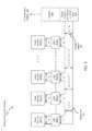
- FIG. 1 aillustrates an embodiment of an energy production system.
- the energy production system 100includes one or more solar modules 101 ( 1 ), 101 ( 2 ), 101 ( 3 ), . . . , 101 ( n ) (n is any positive integer), a string bus 110 , and a controller 150 .
- a “solar module”means a device comprising one or more solar cells connected in series or parallel. Solar cells are configured to absorb and convert photons into electricity. While solar cells can be designed to operate with visible and near-visible wavelength photons, solar cells can also absorb and convert to electricity photons having other wavelengths.
- the first solar module 101 ( 1 )may generate a first voltage V 1 (e.g., 30V), but the voltage V 1 ′ provided to the string bus 110 may be only a portion of V 1 (e.g., 20V).
- a “string bus”means a conductive medium (e.g., wire, cable, lead, to name a few) configured to carry energy from the solar modules 101 ( 1 ), 101 ( 2 ), 101 ( 3 ), . . . , 101 ( n ) to a voltage output 120 .
- the one or more solar modules 101 ( 1 ), 101 ( 2 ), 101 ( 3 ), . . . , 101 ( n )can be connected to the string bus 110 (also referred to as a string or serial bus string).
- the solar modules 101 ( 1 ), 101 ( 2 ), 101 ( 3 ), . . . , 101 ( n )can be connected serially to the string bus 110 .
- the string bus 110can carry signals.
- a signalcan be modulated on the current or voltage traveling through the string bus 110 to or from the solar modules 101 ( 1 ), 101 ( 2 ), 101 ( 3 ), . . . , 101 ( n ).
- Such signalscan represent data such as voltages and currents at different points in the system or instructions/commands for limiting solar module voltage output to name a few.
- Each solar module 101 ( 1 ), 101 ( 2 ), 101 ( 3 ), . . . , 101 ( n )can provide a voltage to the string bus 110 .
- the first solar module 102can provide a first voltage V 1 ′ to the string bus 110 ;
- the second solar module 104can provide a second voltage V 2 ′ to the string bus 110 ;
- the third solar module 106can provide a third voltage V 3 ′ to the string bus 110 , etc.
- the voltage on a segment (or portion) of the string bus 110 between any two solar modules 101 ( 1 ), 101 ( 2 ), 101 ( 3 ), . . . , 101 ( n )is equal to the sum of the voltage contributions from each solar module that came before that segment.
- V 2the voltage on the string bus 110 between the second solar module 101 ( 2 ) and the third solar module 101 ( 3 ) is V 2 .
- This voltage V 2is equal to the sum of the first voltage V 1 ′ and the second voltage V 2 ′.
- V 2V 1 ′+V 2 ′.
- V 2V 1 +V 2 ′.
- each solar module 101 ( 1 ), 101 ( 2 ), 101 ( 3 ), . . . , 101 ( n ) provides to the string bus 110can be controlled (limited or regulated) by the controller 150 .
- the controller 150may be able to prevent a voltage on the string bus from exceeding a predefined limit.
- the predefined limitcan be a regulatory or safety limitation.
- the controller 150is connected to each solar module 101 ( 1 ), 101 ( 2 ), 101 ( 3 ), . . . , 101 ( n ).
- the controller 150can monitor currents and voltages on the string bus 110 and currents and voltages provided to the string bus 110 by the solar modules 101 ( 1 ), 101 ( 2 ), 101 ( 3 ), . . . , 101 ( n ). In an embodiment (not illustrated), the controller 150 can wirelessly communicate with the solar modules 101 ( 1 ), 101 ( 2 ), 101 ( 3 ), . . . , 101 ( n ).
- a “controller”means a device that is an intelligent master to other subordinate devices. For instance, a solar module may be generating 30V, but the controller 150 may instruct the solar module to provide only 20V to the string bus 110 .
- the controller 150can ensure that the voltage on any part of the string bus 110 does not exceed a threshold (or voltage threshold).
- this thresholdis related to a regulatory voltage limit (e.g., 600V in the United States and 1000V in Europe).
- the thresholdis slightly lower than the regulatory limit thus providing a margin of error relative to the regulatory limit or buffer.
- this thresholdis related to a safety voltage limit.
- the voltage provided to the string bus 110 by a solar module 101 ( 1 ), 101 ( 2 ), 101 ( 3 ), . . . , 101 ( n )may be limited by one or more switchable connections.
- the switchable connectionsmay be coupled between each solar module 101 ( 1 ), 101 ( 2 ), 101 ( 3 ), . . . , 101 ( n ) and the string bus 110 .
- a switchable connectionmay comprise a switch, a gate, a transistor, or any other device configured to limit the current or voltage passing between the solar modules 101 ( 1 ), 101 ( 2 ), 101 ( 3 ), . . . , 101 ( n ) and the string bus 110 .
- the word “limit”should not be construed to mean a complete on or off state. In some embodiments, this may be true (e.g., a mechanical switch). However, in some embodiments, switches only decrease the current or voltage.
- the voltage output 120can be connected to any number of devices or other energy transporting mediums (e.g., power lines, other buses, to name a few).
- the voltage output 120can be connected to an inverter 140 , or to a string combiner 130 and an inverter 140 .
- the string combiner 130may also be known as a fuse box or chock box.
- the inverter 140can provide power to an electric grid, to a battery, or to some other energy-using device or system.
- the controller 150is part of the inverter 140 or the string combiner 130 .
- FIG. 1 billustrates another embodiment of an energy storage system.
- the illustrated embodiment of energy storage systemincludes a controller 150 connected directly to the string bus 110 .
- the controller 150can monitor voltages via the string bus 110 .
- the controller 150can also communicate instructions and/or data regarding the voltages to the solar modules 101 ( 1 ), 101 ( 2 ), 101 ( 3 ), . . . , 101 ( n ) via the string bus 110 , via wireless connection, or via both.
- the controller 150can also communicate instructions and/or data regarding the voltages to the LMU's (not illustrated) via the string bus 110 .
- controller 150connects to a bottom line of the string bus 110 , it should be understood that such a configuration is non-limiting.
- the controller 150can be connected to the string bus 110 in series or in parallel.
- the controller 150can also communicate with the inverter 140 or the string combiner 130 via the string bus 110 , wireless connections, or a combination of both.
- controller 150 illustrated in FIGS. 1 a and 1 bis connected to the solar modules 101 ( 1 ), 101 ( 2 ), 101 ( 3 ), . . . , 101 ( n ), it will be seen in the following discussion of FIGS. 2-4 that other embodiments of the controller 150 are also possible.
- FIG. 2illustrates an energy production system where the voltage provided to the string bus from each solar module is controlled by a LMU.
- the energy storage system 200includes one or more solar modules 201 ( 1 ), 201 ( 2 ), 201 ( 3 ), . . . , 201 ( n ) (n is any positive integer), a string bus 210 , and a controller 250 .
- the energy storage system 200also includes LMU's 202 ( 1 ), 202 ( 2 ), 202 ( 3 ), . . . , 202 ( n ) coupled between the solar modules 201 ( 1 ), 201 ( 2 ), 201 ( 3 ), . . .
- a “LMU”means a device configured to limit (or regulate or manage or control) the voltage that a solar module provides to a string bus.
- a LMUmay be variously referred to as a solar module controller (or converter) or link module unit.
- the LMU's 202 ( 1 ), 202 ( 2 ), 202 ( 3 ), . . . , 202 ( n )can limit a portion of the voltages provided to the string bus 210 from each solar module 201 ( 1 ), 201 ( 2 ), 201 ( 3 ), . . . , 201 ( n ).
- the output voltage V Omay exceed the threshold value (a regulatory or safety limit).
- the LMU 202 ( n )may limit a portion of the voltage provided to the string bus 210 to V n ′′.
- the output voltage V Owill remain below the threshold voltage.
- each LMU 202 ( 1 ), 202 ( 2 ), 202 ( 3 ), . . . , 202 ( n )acts as a voltage converter capable of down converting each solar module voltage output.
- the LMU's 202 ( 1 ), 202 ( 2 ), 202 ( 3 ), . . . , 202 ( n )limit the voltage that the solar modules 201 ( 1 ), 201 ( 2 ), 201 ( 3 ), . . . , 201 ( n ) provide to the string bus 210 via a switchable connection.
- a “switchable connection”is a connection between two conductors that can be opened and closed.
- a switchable connectionis one in which current can be selectively allowed to pass or not.
- Switchable connectionsoften comprise a switch such as a gate or transistor.
- a switchable connectionhas two states, on and off.
- the on statepasses 100% of the current and voltage. In an embodiment, the on state passes slightly less than 100% of the current and/or voltage. In an embodiment, the off state passes 0% of the current and voltage. In an embodiment, the off state passes slightly greater than 0% of the current and/or voltage.
- the associated LMU 202 ( 1 ), 202 ( 2 ), 202 ( 3 ), . . . , 202 ( n )need not limit the voltage output.
- the LMU's 202 ( 1 ), 202 ( 2 ), 202 ( 3 ), . . . , 202 ( n )may be turned off when voltage limiting is not required.
- the controller 250is connected to the LMU's 202 ( 1 ), 202 ( 2 ), 202 ( 3 ), . . . , 202 ( n ). In an embodiment, the controller 250 controls the LMU's 202 ( 1 ), 202 ( 2 ), 202 ( 3 ), . . . , 202 ( n ). In an embodiment (not illustrated), the controller 250 communicates to the LMU's 02 ( 1 ), 202 ( 2 ), 202 ( 3 ), . . . , 202 ( n ) via wired connection, wirelessly (not illustrated), or both.
- the controller 250can monitor the voltages V 1 ′, V 2 ′, V 3 ′, . . . , V n ′ provided to the LMU's 202 ( 1 ), 202 ( 2 ), 202 ( 3 ), . . . , 202 ( n ) from each solar module 201 ( 1 ), 201 ( 2 ), 201 ( 3 ), . . . , 201 ( n ).
- the solar modules 201 ( 1 ), 201 ( 2 ), 201 ( 3 ), . . . , 201 ( n )can monitor the voltages V 1 ′, V 2 ′, V 3 ′, . . .
- V n ′provided to the LMU's 202 ( 1 ), 202 ( 2 ), 202 ( 3 ), . . . , 202 ( n ) from each solar module 201 ( 1 ), 201 ( 2 ), 201 ( 3 ), . . . , 201 ( n ).
- the solar modules 201 ( 1 ), 201 ( 2 ), 201 ( 3 ), . . . , 201 ( n )can communicate data regarding the voltages V 1 ′, V 2 ′, V 3 ′, . . .
- V n ′to the controller 250 via a direct wired or wireless connection or via the LMU's 202 ( 1 ), 202 ( 2 ), 202 ( 3 ), . . . , 202 ( n ).
- the LMU's 202 ( 1 ), 202 ( 2 ), 202 ( 3 ), . . . , 202 ( n )can monitor the voltages V 1 ′, V 2 ′, V 3 ′, . . . , V n ′ and provide data regarding the voltages V 1 ′, V 2 ′, V 3 ′, . . . , V n ′ to the controller 250 .
- the controller 250 or the LMU's 202 ( 1 ), 202 ( 2 ), 202 ( 3 ), . . . , 202 ( n )can also monitor the voltage outputs V 1 ′′, V 2 ′′, V 3 ′′, . . . , V n ′′ from the LMU's 202 ( 1 ), 202 ( 2 ), 202 ( 3 ), . . . , 202 ( n ) (the voltage provided to the string bus 210 ).
- another devicesuch as a current/voltage monitoring device, can monitor currents and voltages.
- the current/voltage monitoring devicecan monitor currents and voltages on the string bus, or currents and voltages generated by the solar modules.
- the current/voltage monitoring devicecan then communicate data representing the monitored currents and voltages to LMU's or the controller (depending on the embodiment).
- the controller 250is configured to predict a voltage contribution to the string bus 210 for each solar module 201 ( 1 ), 201 ( 2 ), 201 ( 3 ), . . . , 201 ( n ).
- the controller 250may be further configured to determine if the predicted voltage contribution for each solar module 201 ( 1 ), 201 ( 2 ), 201 ( 3 ), . . . , 201 ( n ) exceeds a predefined voltage limit associated with a solar module.
- the predefined voltage limitmay be a value unique to each solar module 201 ( 1 ), 201 ( 2 ), 201 ( 3 ), . . . , 201 ( n ).
- the controller 250may be further configured to identify each solar module 201 ( 1 ), 201 ( 2 ), 201 ( 3 ), . . . , 201 ( n ) and the associated local management unit 202 ( 1 ), 202 ( 2 ), 202 ( 3 ), . . . , 202 ( n ) having a predicted voltage contribution exceeding the predefined voltage limit.
- the controller 250may be further configured to instruct each identified local management unit to limit the voltage contribution.
- the controller 250is configured to predict a voltage across a portion of the string bus 210 spanning between two solar modules or LMU's.
- the controller 250may further be configured to determine if the predicted voltage exceeds a voltage limit threshold.
- a controlling local management unitis configured to predict a voltage contribution to the string bus 210 for each solar module 201 ( 1 ), 201 ( 2 ), 201 ( 3 ), . . . , 201 ( n ).
- the controlling local management unitmay be further configured to determine if the predicted voltage contribution for each solar module 201 ( 1 ), 201 ( 2 ), 201 ( 3 ), . . . , 201 ( n ) exceeds a predefined voltage limit.
- the controlling local management unitmay be further configured to identify each solar module 201 ( 1 ), 201 ( 2 ), 201 ( 3 ), . . .
- the controlling LMUmay be further configured to instruct each identified local management unit to limit the voltage contribution.
- either the controller, the solar modules, or the local management unitscan monitor currents and/or voltage provided to the string bus from the solar modules or can monitor currents and/or voltages on the string bus.
- the controller, the solar modules, the local management unit, or a controlling local management unitcan analyze data regarding currents and/or voltages. From this analysis, the controller, the solar modules, the local management units, or the controlling local management unit can determine how to control voltages provided to the string bus so as to prevent voltages on the string bus from exceeding regulatory or safety limits.
- FIG. 3illustrates an energy storage system where the controller comprises LMU's.
- the energy storage system 300includes one or more solar modules 301 ( 1 ), 301 ( 2 ), 301 ( 3 ), . . . , 301 ( n ) (n is any positive integer), a string bus 310 , and LMU's 302 ( 1 ), 302 ( 2 ), 302 ( 3 ), . . . , 302 ( n ).
- the controlleris not separate from the LMU's 302 ( 1 ), 302 ( 2 ), 302 ( 3 ), . . . , 302 ( n ), but rather comprises them.
- the LMU's 302 ( 1 ), 302 ( 2 ), 302 ( 3 ), . . . , 302 ( n )carry out functions that a controller might carry out including, but not limited to, monitoring voltages, determining which voltages provided to the string bus 310 should be limited, predicting future voltages, comparing voltages to voltage thresholds, and limiting the voltages provided to the string bus 310 by each solar module 301 ( 1 ), 301 ( 2 ), 301 ( 3 ), . . . , 301 ( n ).
- the LMU's 302 ( 1 ), 302 ( 2 ), 302 ( 3 ), . . . , 302 ( n )can monitor voltages. In determining which voltages from solar modules 301 ( 1 ), 301 ( 2 ), 301 ( 3 ), . . . , 301 ( n ) should be limited, the LMU's 302 ( 1 ), 302 ( 2 ), 302 ( 3 ), . . . , 302 ( n ) may communicate with each other either via wired connection, wirelessly (not illustrated), or both.
- one of the LMU's 302 ( 1 ), 302 ( 2 ), 302 ( 3 ), . . . , 302 ( n )can act as the controller.
- the controlling LMU 302 ( 1 ), 302 ( 2 ), 302 ( 3 ), . . . , 302 ( n )can determine the voltages that the other LMU's 302 ( 1 ), 302 ( 2 ), 302 ( 3 ), . . . , 302 ( n ) should provide to the string bus 310 .
- 302 ( n )can also perform all analyses in determining which LMU's 302 ( 1 ), 302 ( 2 ), 302 ( 3 ), . . . , 302 ( n ) should limit voltages provided to the string bus 310 .
- the controlling LMUcan be selected using any suitable protocol.
- the first LMU that announces its intent to take control of other LMU'scan become the controlling LMU.
- the LMU's 302 ( 1 ), 302 ( 2 ), 302 ( 3 ), . . . , 302 ( n )can do this monitoring and analysis in accord or individually. For instance, one LMU can monitor the voltage output of the solar module that the LMU is connected to. One LMU can also monitor the voltages on the string bus 310 . This same LMU can then determine how much voltage provided by the solar module should be provided to the string bus 310 , and limit the voltage accordingly. Such operations can take place independent of the other LMU's 302 ( 1 ), 302 ( 2 ), 302 ( 3 ), . . . , 302 ( n ).
- FIG. 4illustrates an energy storage system where LMU's reside on the solar modules.
- the energy storage system 400includes one or more solar modules 401 ( 1 ), 401 ( 2 ), 401 ( 3 ), . . . , 401 ( n ) (n is any positive integer), a string bus 410 , and LMU's 402 ( 1 ), 402 ( 2 ), 402 ( 3 ), . . . , 402 ( n ).
- the controlleris again embodied by the set of LMU's 402 ( 1 ), 402 ( 2 ), 402 ( 3 ), . . . , 402 ( n ).
- the LMU's 402 ( 1 ), 402 ( 2 ), 402 ( 3 ), . . . , 402 ( n )are incorporated into the solar modules 401 ( 1 ), 401 ( 2 ), 401 ( 3 ), . . . , 401 ( n ). From the solar modules, 401 ( 1 ), 401 ( 2 ), 401 ( 3 ), . . . , 401 ( n ) the LMU's 402 ( 1 ), 402 ( 2 ), 402 ( 3 ), . . .
- the solar modules 401 ( 1 ), 401 ( 2 ), 401 ( 3 ), . . . , 401 ( n ) or the LMU's 402 ( 1 ), 402 ( 2 ), 402 ( 3 ), . . . , 402 ( n )can monitor voltages.
- the LMU's 402 ( 1 ), 402 ( 2 ), 402 ( 3 ), . . . , 402 ( n )can work together or independently.
- the LMU's 402 ( 1 ), 402 ( 2 ), 402 ( 3 ), . . . , 402 ( n )can communicate with each other via wired connections, via wireless connection, or via both.
- communications between componentscan be performed at least via the following three methods alone or in combination: wired connection, wireless connection, or the string bus. Multiple signals can be communicated via a single connection (e.g., multiplexing).
- FIG. 5illustrates a solar module having a plurality of solar cells controlled by one or more LMU's.
- the solar module 500has one or more strings of solar cells 506 .
- a LMU 504can control the voltage output of a group of cells 502 .
- a LMU 504can control the voltage output of individual cells 502 .
- a string of solar cells 506may be connected in series, in parallel, or in a mesh configuration.
- the LMU 504can control the voltage output of the string 506 or two or more LMU's 504 can be connected in series to form a string.
- the stringcan be connected to output connections for the solar module 500 .
- FIGS. 6-7illustrate LMU's according to some embodiments.
- LMU's 602may be configured to switch on and off the solar module 601 periodically to limit the voltage provided to the string bus 610 from each solar module 601 .
- One example of a LMU 602is any of the various LMU's (solar module controllers) offered by Tigo Energy, Inc. of Los Gatos, Calif.
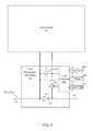
- FIG. 6illustrates a portion of an embodiment of an energy storage unit comprising a solar module, a LMU, and a portion of a string bus.
- a LMU 602is local to the solar module 601 and can be used to periodically couple the solar module 601 to the string bus 610 via the switch Q 1 606 . By periodically switching switch Q 1 606 , the voltage provided to the string bus 610 can be limited.
- the string bus 610may or may not be part of an overall mesh configuration of solar modules 601 .
- the switch Q 1 606can be switched at a particular duty cycle.
- a “duty cycle”is the amount of time that a switch is closed (i.e., passing current).
- a duty cycle of 25%provides about a quarter of the solar module's 601 voltage to the string bus 610 since, and assuming a one second period, the switch is closed for 0.25 seconds and open for 0.75 seconds.
- a 100% duty cycleprovides about 100% of the solar module's 601 voltage to the string bus 610 since the switch is continuously closed and connecting a solar module to the string bus 610 .
- the LMU 602may include a local controller 609 to control connectivity to the string bus 603 .
- the local controller 609controls connectivity to the string bus 603 via the switch Q 1 606 .
- Such controlmay be based on parameters such as duty cycle 604 a , phase 604 b , and synchronization pulse 604 c .
- the command to control the operation of the switch Q 1 606is sent to the LMU 602 over the photovoltaic (PV) string bus (power line) 610 .
- PVphotovoltaic
- separate network connectionscan be used to transmit the data and/or commands to/from the LMU 602 .
- Wireless communicationsare also possible.
- the switch Q 1 606 duty cyclecan be adjusted by the LMU 602 based on measurements taken by the LMU 602 .
- the duty cyclecan be adjusted by the LMU 602 based on measurements taken by one or more other LMU's or by a controller 150 (as in FIG. 1 a ).
- the LMU 602is an example of a switchable connection.
- the controller 250monitors the duty cycles of the LMU's 202 ( 1 ), 202 ( 2 ), 202 ( 3 ), . . . , 202 ( n ) and communicates data and/or signals representing the duty cycles to the LMU's 202 ( 1 ), 202 ( 2 ), 202 ( 3 ), . . . , 202 ( n ).
- 202 ( n )can communicate duty cycles to each other and determine their duty cycles based on those of the other LMU's.
- the LMU's 202 ( 1 ), 202 ( 2 ), 202 ( 3 ), . . . , 202 ( n )can communicate duty cycles to a single LMU acting as the controller. That single LMU can then determine appropriate duty cycles for each LMU and communicate instructions for the other LMU's to operate at the determined duty cycles.
- the LMU 602may receive inputs 604 a , 604 b , 604 c , which are illustrated separately. However, the inputs 604 a , 604 b , 604 c are not necessarily communicated to the LMU 602 via separate connections. In one embodiment the inputs 604 a , 604 b , 604 c may be received in the LMU via a single wired connection. In one embodiment, the inputs 604 a , 604 b , 604 c are received in the LMU 602 via the string bus 610 .
- the local controller 609receives the parameters 604 a , 604 b , 604 c from another LMU via the string bus 610 or a separate data communication connection (e.g., a separate data bus or a wireless connection, to name a few). In an embodiment, the local controller 609 receives the parameters 604 a , 604 b , 604 c from a controller such as that depicted in FIG. 1 a . In some embodiments, the local controller 609 may determine a parameter (e.g., 604 a and 604 b ) based on the operating parameters of the solar module 601 and/or measurements obtained by the local controller 609 without communicating with other LMU's or a controller.
- a parametere.g., 604 a and 604 b
- the LMU 602may include a capacitor C 1 605 to assist in filtering and/or ensuring that the voltage provided to the string bus 610 is relatively constant. As illustrated in FIG. 6 , the solar module 601 is connected in parallel to the capacitor C 1 605 .
- the LMU 602may include a diode D 1 607 to prevent current from traveling backwards in the string bus, for example in the case of a failure of the panel connected to said LMU. As illustrated in FIG. 6 , the diode D 1 607 is connected in series with the string bus 610 .
- the switch Q 1 606 of the LMU 602can selectively connect or disconnect the solar module 601 and the capacitor C 1 605 from a parallel connection with the diode D 1 607 . In so doing, the switch Q 1 606 connects or disconnects the solar module 601 from the string bus 610 .
- the solar module 601When the switch Q 1 606 is on (closed), the solar module 601 provides energy to the string bus 610 and is supported by the capacitor C 1 605 allowing a current larger than the current that could be provided solely by the solar panel. When the switch Q 1 606 is off (open), the solar module 601 does not provide energy to the string bus 610 but rather the solar module 601 charges the capacitor C 1 605 so it can discharge a portion of its energy during the next cycle. In other words, the capacitor C 1 605 acts to smooth the voltage output which would otherwise have a square wave profile.
- an active switchmay be added in parallel to diode D 1 607 to further enhance its efficiency (not illustrated)
- Additional filtersmay be may be used outside the diode D 1 607 to reduce noise in the string (e.g., capacitors, resistors, inductors, or any combination of these, to name a few).
- FIG. 7illustrates a portion of another embodiment of an energy storage unit comprising a solar module, a LMU, and a portion of a string bus.
- the LMU 702is connected between the solar module 701 and the string bus 710 to control or limit the voltage provided to the string bus 710 . Commands to the LMU 702 can be sent over the photovoltaic (PV) string bus (power line) 710 .
- the inputs 704 a , 704 b , 704 c to the local controller 709were drawn separately, which does not necessarily indicate that the inputs 704 a , 704 b , 704 c are provided via separate connections and/or from outside the LMU 702 .
- the local controller 709may determine the parameters 704 a , 704 b , 704 c based on measurements obtained at the LMU 702 , with or without data from outside the LMU 702 .
- FIG. 7like FIG. 6 , includes a LMU 702 coupling the solar module 701 to the string bus 710 .
- the LMU 702periodically connects and disconnects the solar module 701 to and from the string bus 710 .
- the LMU 702is parallel coupled to the solar module 701 and series connected to the string bus 710 .
- the LMU 702can be serially connected to other LMU's.
- the LMU 702has a switchable connection (e.g., switch Q 1 706 ) configured to connect and disconnect the solar module 701 to the string bus 710 .
- the LMU 702may receive, among others, three inputs or types of input data, including the following: (a) requested duty cycle 704 a , which can be expressed as a percentage (e.g., from 0 to 100%) of time the solar module 701 is to be connected to the string bus 710 via the switch Q 1 706 , (b) a phase shift 704 b in degrees (e.g., from 0 degree to 180 degree) and (c) a timing or synchronization pulse 704 c .
- These inputscan be supplied as discrete signals, or can be supplied as data on a network, or composite signals sent through the power lines (e.g., string bus 710 ) or wirelessly, and in yet other cases, as a combination of any of these input types.
- the LMU 702includes a capacitor C 1 705 and the switch Q 1 706 , as well as a diode D 1 707 .
- the diode D 1 707is supplemented with an additional switch Q 2 708 , which acts as a synchronous rectifier to increase efficiency.
- the additional switch Q 2 708is open (off) when the switch Q 1 706 is closed (on) to connect the solar module 701 (and the capacitor C 1 705 ) to the string bus 710 .
- the additional switch Q 2 708can be closed (on) to divert the current on the string bus 710 around the diode D 1 707 . In this fashion, losses from passing current through the forward-biased diode D 1 707 can be avoided.
- a filter(not shown), including a serial coil and a parallel capacitor, can be used.
- the filtermay be placed at the LMU or placed just before the fuse box or inverter, or be part of either one of those.
- the controller 709is used to process the input signals (e.g., 704 a , 704 b , 704 c ) and drive the switches Q 1 706 and Q 2 708 .
- the controller 709is a small single chip micro controller (SCMC).
- SCMCsmall single chip micro controller
- the controller 709may be implemented using Application-Specific Integrated Circuit (ASIC) or Field-Programmable Gate Array (FPGA).
- ASICApplication-Specific Integrated Circuit
- FPGAField-Programmable Gate Array
- the controller 709can even be implemented in discrete, functionally equivalent circuitry, or in other cases a combination of SCMC and discrete circuitry. It will be generally referred to as single chip micro controller (SCMC) herein, but any implementation may be used.
- SCMCsingle chip micro controller
- the local controller 709is coupled to the solar module 701 in parallel to obtain power for processing; and the controller 709 is coupled to the string bus 710 to obtain signals transmitted from other LMU's coupled to the string bus 710 , and to monitor currents and voltages on the string bus 710 .
- the switches in different LMU'scan operate at different phases to minimize voltage variance on the string bus. For example given two LMU's operating at a 50% duty cycle, the local controller of each LMU could be cycled 180 degrees (one half cycle) out of phase. As such, when one local controller opened the connection to its solar module, the other local controller closed the connection to its solar module. The result is a steadier supply of voltages to the string bus than if the two solar modules were connected and disconnected to the string bus at the same times.
- the local controller (SCMC) 709is connected (not shown in FIG. 7 ) to the solar module 701 to obtain power for controlling the switches Q 1 706 and Q 2 708 .
- the local controller (SCMC) 709is further connected (not shown in FIG. 7 ) to the string bus 710 to transmit and/or receive information from the string bus 710 .
- the local controller (SCMC) 709includes sensors (not shown in FIG. 7 ) to measure operating parameters of the solar module 701 , such as module voltage, module current, temperature, light intensity, etc.
- an energy production systemmay comprise a string bus, a solar module connected to the string bus and generating a voltage, and a controller in communication with the solar module and the string bus.
- the controllermay be configured to control what portion of the voltage is provided to the string bus based on a predicted future voltage.
- a “predicted future voltage”is an estimated voltage existing at a particular future time.
- the controllermay monitor the string bus and note that the string bus voltage is likely to exceed a regulatory limit within five minutes. The expected voltage in five minutes is called the predicted future voltage.
- the controllermay limit the voltage contribution of one or more solar modules to the string bus so that the string bus voltage remains below the regulatory limit, in some cases preferably in a balanced manner.
- the portion of a solar module's voltage provided to the string busmay be roughly inversely related to the magnitude of the predicted future voltage. In other words, the greater the predicted future voltage, the lower the voltage provided to the string bus.
- the predicted future voltagecan also be determined via a voltage trend.
- a voltage trendmay include data or analysis of data regarding voltages that have been monitored. This historical data or trend data can be used to estimate what the predicted future voltage will be.
- the voltage provided to the string busmay be limited to a default voltage.
- the voltage provided to the string bus from one or more solar modulescan be limited to a predefined default value. For instance, when the string bus voltage approaches a regulatory limit, the voltage from each solar module provided to the string bus can be limited to 50% of each solar module's maximum output. Alternatively, when the string bus voltage or some other monitored voltage becomes excessive or is predicted to become excessive, one or just a few solar modules can be limited to contributing 50% of their output voltage to the string bus.
- a voltage thresholdmay be used to determine when one or more solar modules should be limited to providing a default voltage to the string bus.
- the voltages that each solar module provides to the string busmay be limited to a default value (e.g., 75% of output or 50% of output or 25% of output, to name a few).
- a default valuee.g., 75% of output or 50% of output or 25% of output, to name a few.
- turning to the default voltagecan be triggered by a hardware (e.g., differential amplifier and a Zener diode threshold) or software safety mechanism.
- the controllermonitors a certain rate of change it may trigger commands to the LMU's to fall back to the default voltage.
- the controllercan communicate with any other part of the energy production system via one or more of the LMU's.
- the controllercan monitor voltages on the string bus via a LMU. For instance, the controller can monitor voltage on the string bus via data gathered by each of the LMU's.
- FIG. 8illustrates a method for carrying out the functions of the systems herein disclosed.
- the method 800includes a monitor first voltage operation 802 in which a first voltage is monitored across a first string bus section.
- the first string bus sectionincludes a portion of the string bus connecting a first solar module to a second solar module.
- the first voltagewill thus include the voltage provided to the string bus by the first solar module plus any voltage already contributed to the string bus via upstream solar modules (downstream being the direction that current travels).
- the method 800also includes a monitor second voltage operation 804 in which a second voltage is monitored across a second string bus section.
- the second string bus sectionincludes a portion of the string bus connecting a second solar module to a downstream solar module or an output voltage.
- the output voltagecan be connected to any number of devices or systems including a string combiner, an inverter, a power grid, or power lines, to name a few.
- the second voltagewill thus include the voltage provided to the string bus by the second solar module plus the voltage provided by the first solar module plus any voltage already contributed to the string bus via upstream solar modules.
- the first and second monitor voltage operations 802 , 804can operate simultaneously. In an embodiment, one of the two operations 802 , 804 can follow the other in time. In an embodiment, the first and second monitor voltage operations 802 , 804 may operate over different periods of time while a portion of those periods of time may overlap.
- the method 800also includes a limit first voltage or second voltage operation 806 .
- the limit operation 806may limit the first voltage by limiting the voltage output of the first solar module. With reference to FIGS. 8-10 , voltage is measured on the string bus, while voltage output is the voltage provided to the string bus from a solar module.
- the limit operation 806may limit the second voltage by limiting the voltage output of the second solar module.
- the limit operation 806may limit the first and second voltages, to the same or different values, by limiting the voltage output of the first and second solar modules. Limiting voltage output can be performed via any of the systems and methods described previously or with reference to FIGS. 1-7 . Determining when and by how much voltage will be limited can also be performed via any of the systems and methods previously described or with reference to FIGS. 1-7 .
- monitoring operations 802 , 804 and the limiting operation 806do not have to operate sequentially.
- the limiting operation 806can be carried out while monitoring continues. In other words, monitoring can be a continuous process or discrete (currents and voltages monitored at periodic intervals).
- FIG. 9illustrates another method for carrying out the functions of the systems herein disclosed.
- the method 900includes a monitor first voltage operation 902 in which a first voltage is monitored across a first string bus section.
- the first string bus sectionincludes a portion of the string bus connecting a first solar module to a second solar module.
- the first voltagewill thus include the voltage provided to the string bus by the first solar module plus any voltage already contributed to the string bus via upstream solar modules (downstream being the direction that current travels).
- the method 900also includes a monitor second voltage operation 904 in which a second voltage is monitored across a second string bus section.
- the second string bus sectionincludes a portion of the string bus connecting a second solar module to a downstream solar module or an output voltage.
- the output voltagecan be connected to any number of devices or systems including a string combiner, an inverter, a power grid, or power lines, to name a few.
- the second voltagewill thus include the voltage provided to the string bus by the second solar module plus the voltage provided by the first solar module plus any voltage already contributed to the string bus via upstream solar modules.
- the first and second monitor voltage operations 902 , 904can operate simultaneously. In an embodiment, one of the two operations 902 , 904 can follow the other in time. In an embodiment, the first and second monitor voltage operations 902 , 904 may operate over different periods of time while a portion of those periods of time may overlap.
- the method 900compares the first and second voltages to a threshold voltage via a determination operation 905 .
- the determination operation 905determines whether the first or second voltages exceed the voltage threshold. Such comparison can be performed, for instance, as a backup safety measure. Normally, the system predicts future voltages, and can scale back voltage output from solar modules in order to account for unusually high solar module voltage generation. However, sometimes string bus voltage may rise faster than the system can react to. In such an instance the determination operation 905 can lead to initiation of an automatic voltage limitation—a backup safety measure. One or more of the solar modules can automatically be instructed to limit output voltage to a specified low level when the voltage threshold is exceeded.
- the method 900ensures that solar module voltage outputs will be quickly and significantly reduced if the string bus voltage gets too close to a safety or regulatory limit.
- the threshold voltagemay be different for each section of the string bus.
- the voltage output of the first or second solar modulewhen either the first or second voltages exceed the voltage threshold, the voltage output of the first or second solar module (or both), whichever is generating excessive voltage, can be limited. In an embodiment, when either the first or second voltages (or both) exceed the voltage threshold, the voltage output of the first and second solar modules can be limited. Such, an embodiment might be used where greater safety is desired than in the embodiment where only select solar module output voltages are limited.
- the method 900includes a limit first voltage and second voltage operation 906 .
- the limit operation 906may limit the first voltage by limiting the voltage output of the first solar module.
- the limit operation 906may limit the second voltage by limiting the voltage output of the second solar module.
- the limit operation 906may limit the first and second voltages by limiting the voltage output of the first and second solar modules. Limiting voltage output can be performed via any of the methods and systems described in earlier paragraphs and with reference to FIGS. 1-7 .
- the method 900can loop back to the monitor operations 902 , 904 .
- the monitor operations 902 , 904can reinitiate after the determination operation 905 , can automatically operate at a periodic interval, or can continuously monitor voltages.
- FIG. 10illustrates another method for carrying out the functions of the systems herein disclosed.
- the duty cycle of all LMU'scan be adjusted in order to limit or regulate the string bus voltage.
- the duty cyclesmay be adjusted so that the voltage provided to the string bus do not cause the string bus voltage to exceed the maximum voltage allowed (e.g., regulatory or safety limits, to name two).
- the maximum voltagemay be limited by the string combiner 130 , the inverter 140 , or any other load connected to the string bus 110 , or limited by any regulations applicable to that system.
- the duty cyclesare adjusted to align the voltage of multiple strings.
- the method 1000includes a monitor first voltage operation 1002 and a monitor second voltage operation 1004 .
- the method 1000also includes a limit first or second voltages operation 1006 .
- the limit operation 1006limits the voltage output from either the first or second solar modules depending on which one (or both) is generating a voltage that is or may cause the string bus voltage to exceed the maximum allowable voltage. This is done via adjusting the duty cycle of switchable connections coupling the solar modules to the string bus. There is at least one switchable connection between each solar module and the string bus.
- the duty cyclesare computed for the solar modules that are connected to a string bus via corresponding LMU's.
- the duty cyclescan be calculated based on measured current and voltages of the solar modules.
- the duty cyclescan be further fine tuned and/or re-adjusted to changes in current and/or voltage.
- target voltagesare computed for the solar modules, and the duty cycles are adjusted so that the voltages provided to the string bus converge towards the target voltages.
- the methods to compute the duty cycles of the solar modulescan also be used to compute the duty cycles of the groups of solar cells within a solar module (recall FIG. 5 ).
- controllers and/or LMU'scan comprise hardware, hardware and software, or software.
- the controllercan be further connected to a private network (e.g., intranet) or the Internet. The controller could then communicate with other computers and servers. One application of such a connection would allow the controller to determine the local regulatory voltage limits and modify voltage thresholds and voltage limiting algorithms accordingly to tailor the system to those local regulatory voltage limits.
- the balance between hardware and firmware in the controllers or LMU'scan be changed without departing from the spirit of the invention.
- the controller or LMU'smay have a default voltage limit at which they operate until communications can be established.
- the methods for determining the duty cycles for the solar modulescan also be used to determine the duty cycles of groups of cells connected via LMU's in a string of solar cells within a solar module.
- the controllercan be off the shelf and possibly modified. In one embodiment, the controller can have analog circuitry. In one embodiment, the controller can be a microcontroller. In one embodiment, the controller could be a combination of these features.
Landscapes
- Control Of Electrical Variables (AREA)
- Charge And Discharge Circuits For Batteries Or The Like (AREA)
Abstract
Description
Claims (20)
Priority Applications (1)
| Application Number | Priority Date | Filing Date | Title |
|---|---|---|---|
| US13/357,331US8274172B2 (en) | 2009-07-30 | 2012-01-24 | Systems and method for limiting maximum voltage in solar photovoltaic power generation systems |
Applications Claiming Priority (3)
| Application Number | Priority Date | Filing Date | Title |
|---|---|---|---|
| US27321009P | 2009-07-30 | 2009-07-30 | |
| US12/562,933US8102074B2 (en) | 2009-07-30 | 2009-09-18 | Systems and method for limiting maximum voltage in solar photovoltaic power generation systems |
| US13/357,331US8274172B2 (en) | 2009-07-30 | 2012-01-24 | Systems and method for limiting maximum voltage in solar photovoltaic power generation systems |
Related Parent Applications (1)
| Application Number | Title | Priority Date | Filing Date |
|---|---|---|---|
| US12/562,933ContinuationUS8102074B2 (en) | 2009-07-30 | 2009-09-18 | Systems and method for limiting maximum voltage in solar photovoltaic power generation systems |
Publications (2)
| Publication Number | Publication Date |
|---|---|
| US20120119584A1 US20120119584A1 (en) | 2012-05-17 |
| US8274172B2true US8274172B2 (en) | 2012-09-25 |
Family
ID=43526296
Family Applications (2)
| Application Number | Title | Priority Date | Filing Date |
|---|---|---|---|
| US12/562,933Active2030-03-12US8102074B2 (en) | 2009-07-30 | 2009-09-18 | Systems and method for limiting maximum voltage in solar photovoltaic power generation systems |
| US13/357,331ActiveUS8274172B2 (en) | 2009-07-30 | 2012-01-24 | Systems and method for limiting maximum voltage in solar photovoltaic power generation systems |
Family Applications Before (1)
| Application Number | Title | Priority Date | Filing Date |
|---|---|---|---|
| US12/562,933Active2030-03-12US8102074B2 (en) | 2009-07-30 | 2009-09-18 | Systems and method for limiting maximum voltage in solar photovoltaic power generation systems |
Country Status (2)
| Country | Link |
|---|---|
| US (2) | US8102074B2 (en) |
| WO (1) | WO2011014274A1 (en) |
Cited By (68)
| Publication number | Priority date | Publication date | Assignee | Title |
|---|---|---|---|---|
| US8963518B2 (en) | 2004-07-13 | 2015-02-24 | Tigo Energy, Inc. | Device for distributed maximum power tracking for solar arrays |
| US9088178B2 (en) | 2006-12-06 | 2015-07-21 | Solaredge Technologies Ltd | Distributed power harvesting systems using DC power sources |
| US9112379B2 (en) | 2006-12-06 | 2015-08-18 | Solaredge Technologies Ltd. | Pairing of components in a direct current distributed power generation system |
| US9130401B2 (en) | 2006-12-06 | 2015-09-08 | Solaredge Technologies Ltd. | Distributed power harvesting systems using DC power sources |
| US9235228B2 (en) | 2012-03-05 | 2016-01-12 | Solaredge Technologies Ltd. | Direct current link circuit |
| US9291696B2 (en) | 2007-12-05 | 2016-03-22 | Solaredge Technologies Ltd. | Photovoltaic system power tracking method |
| US9318974B2 (en) | 2014-03-26 | 2016-04-19 | Solaredge Technologies Ltd. | Multi-level inverter with flying capacitor topology |
| US9362743B2 (en) | 2008-05-05 | 2016-06-07 | Solaredge Technologies Ltd. | Direct current power combiner |
| US9368964B2 (en) | 2006-12-06 | 2016-06-14 | Solaredge Technologies Ltd. | Distributed power system using direct current power sources |
| US9401599B2 (en) | 2010-12-09 | 2016-07-26 | Solaredge Technologies Ltd. | Disconnection of a string carrying direct current power |
| US9407161B2 (en) | 2007-12-05 | 2016-08-02 | Solaredge Technologies Ltd. | Parallel connected inverters |
| US9537445B2 (en) | 2008-12-04 | 2017-01-03 | Solaredge Technologies Ltd. | Testing of a photovoltaic panel |
| US9543889B2 (en) | 2006-12-06 | 2017-01-10 | Solaredge Technologies Ltd. | Distributed power harvesting systems using DC power sources |
| US9548619B2 (en) | 2013-03-14 | 2017-01-17 | Solaredge Technologies Ltd. | Method and apparatus for storing and depleting energy |
| US9590526B2 (en) | 2006-12-06 | 2017-03-07 | Solaredge Technologies Ltd. | Safety mechanisms, wake up and shutdown methods in distributed power installations |
| US20170104328A1 (en)* | 2015-08-18 | 2017-04-13 | Argentum Electronics, Inc. | Power combiner systems and methods |
| US9647442B2 (en) | 2010-11-09 | 2017-05-09 | Solaredge Technologies Ltd. | Arc detection and prevention in a power generation system |
| US9644993B2 (en) | 2006-12-06 | 2017-05-09 | Solaredge Technologies Ltd. | Monitoring of distributed power harvesting systems using DC power sources |
| US9673711B2 (en) | 2007-08-06 | 2017-06-06 | Solaredge Technologies Ltd. | Digital average input current control in power converter |
| US20170163035A1 (en)* | 2015-08-18 | 2017-06-08 | Argentum Electronics, Inc. | Wide range power distribution systems and methods |
| US9680304B2 (en) | 2006-12-06 | 2017-06-13 | Solaredge Technologies Ltd. | Method for distributed power harvesting using DC power sources |
| US9812984B2 (en) | 2012-01-30 | 2017-11-07 | Solaredge Technologies Ltd. | Maximizing power in a photovoltaic distributed power system |
| US9819178B2 (en) | 2013-03-15 | 2017-11-14 | Solaredge Technologies Ltd. | Bypass mechanism |
| US9831824B2 (en) | 2007-12-05 | 2017-11-28 | SolareEdge Technologies Ltd. | Current sensing on a MOSFET |
| US9853538B2 (en) | 2007-12-04 | 2017-12-26 | Solaredge Technologies Ltd. | Distributed power harvesting systems using DC power sources |
| US9853565B2 (en) | 2012-01-30 | 2017-12-26 | Solaredge Technologies Ltd. | Maximized power in a photovoltaic distributed power system |
| US9866098B2 (en) | 2011-01-12 | 2018-01-09 | Solaredge Technologies Ltd. | Serially connected inverters |
| US9869701B2 (en) | 2009-05-26 | 2018-01-16 | Solaredge Technologies Ltd. | Theft detection and prevention in a power generation system |
| US9876430B2 (en) | 2008-03-24 | 2018-01-23 | Solaredge Technologies Ltd. | Zero voltage switching |
| US9923516B2 (en) | 2012-01-30 | 2018-03-20 | Solaredge Technologies Ltd. | Photovoltaic panel circuitry |
| US9941813B2 (en) | 2013-03-14 | 2018-04-10 | Solaredge Technologies Ltd. | High frequency multi-level inverter |
| US9960667B2 (en) | 2006-12-06 | 2018-05-01 | Solaredge Technologies Ltd. | System and method for protection during inverter shutdown in distributed power installations |
| US9966766B2 (en) | 2006-12-06 | 2018-05-08 | Solaredge Technologies Ltd. | Battery power delivery module |
| US9991717B1 (en) | 2015-06-15 | 2018-06-05 | Roco, Llc | Method and apparatus for connecting and disconnecting a photovoltaic module to a distribution system |
| US10110007B2 (en) | 2008-11-26 | 2018-10-23 | Tigo Energy, Inc. | Systems and methods to balance solar panels in a multi-panel system |
| US20180309301A1 (en)* | 2017-04-21 | 2018-10-25 | Fan Wang | Solar array communications |
| US10115841B2 (en) | 2012-06-04 | 2018-10-30 | Solaredge Technologies Ltd. | Integrated photovoltaic panel circuitry |
| US10187115B2 (en) | 2015-07-13 | 2019-01-22 | Maxim Integrated Products, Inc. | Systems and methods for DC power line communication in a photovoltaic system |
| US10211631B2 (en) | 2013-12-17 | 2019-02-19 | Enphase Energy, Inc. | Voltage clipping |
| US10230427B2 (en) | 2015-07-13 | 2019-03-12 | Maxim Integrated Products, Inc. | Systems and methods for DC power line communication in a photovoltaic system |
| US10230310B2 (en) | 2016-04-05 | 2019-03-12 | Solaredge Technologies Ltd | Safety switch for photovoltaic systems |
| US10348095B2 (en) | 2015-07-13 | 2019-07-09 | Maxim Integrated Products, Inc. | Switching circuits having multiple operating modes and associated methods |
| US10396662B2 (en) | 2011-09-12 | 2019-08-27 | Solaredge Technologies Ltd | Direct current link circuit |
| US10673222B2 (en) | 2010-11-09 | 2020-06-02 | Solaredge Technologies Ltd. | Arc detection and prevention in a power generation system |
| US10673229B2 (en) | 2010-11-09 | 2020-06-02 | Solaredge Technologies Ltd. | Arc detection and prevention in a power generation system |
| US10778482B2 (en) | 2019-02-12 | 2020-09-15 | Texas Instruments Incorporated | Bit slicer circuit for S-FSK receiver, integrated circuit, and method associated therewith |
| US10797921B2 (en) | 2019-02-12 | 2020-10-06 | Texas Instruments Incorporated | Threshold computation circuit for S-FSK receiver, integrated circuit, and method associated therewith |
| US10931119B2 (en) | 2012-01-11 | 2021-02-23 | Solaredge Technologies Ltd. | Photovoltaic module |
| US10965126B2 (en) | 2017-05-01 | 2021-03-30 | Futurewei Technologies, Inc. | Systems and methods for control of photovoltaic arrays |
| US11018623B2 (en) | 2016-04-05 | 2021-05-25 | Solaredge Technologies Ltd. | Safety switch for photovoltaic systems |
| US11133777B2 (en) | 2017-04-21 | 2021-09-28 | Fan Wang | Solar array communications |
| US11177663B2 (en) | 2016-04-05 | 2021-11-16 | Solaredge Technologies Ltd. | Chain of power devices |
| US11190022B2 (en) | 2019-01-09 | 2021-11-30 | Texas Instruments Incorporated | Controller circuit for photovoltaic sub-module |
| US11264947B2 (en) | 2007-12-05 | 2022-03-01 | Solaredge Technologies Ltd. | Testing of a photovoltaic panel |
| US11296650B2 (en) | 2006-12-06 | 2022-04-05 | Solaredge Technologies Ltd. | System and method for protection during inverter shutdown in distributed power installations |
| US11309832B2 (en) | 2006-12-06 | 2022-04-19 | Solaredge Technologies Ltd. | Distributed power harvesting systems using DC power sources |
| US11342787B2 (en) | 2019-03-20 | 2022-05-24 | Texas Instruments Incorporated | Controller circuit for photovoltaic module |
| US11350186B2 (en) | 2019-03-20 | 2022-05-31 | Texas Instruments Incorporated | Monitoring circuit for photovoltaic module |
| US11569659B2 (en) | 2006-12-06 | 2023-01-31 | Solaredge Technologies Ltd. | Distributed power harvesting systems using DC power sources |
| US11687112B2 (en) | 2006-12-06 | 2023-06-27 | Solaredge Technologies Ltd. | Distributed power harvesting systems using DC power sources |
| US11728768B2 (en) | 2006-12-06 | 2023-08-15 | Solaredge Technologies Ltd. | Pairing of components in a direct current distributed power generation system |
| US11735910B2 (en) | 2006-12-06 | 2023-08-22 | Solaredge Technologies Ltd. | Distributed power system using direct current power sources |
| US11791633B2 (en) | 2011-07-11 | 2023-10-17 | Generac Power Systems, Inc. | Systems and methods for increasing output current quality, output power, and reliability of grid-interactive inverters |
| US11855231B2 (en) | 2006-12-06 | 2023-12-26 | Solaredge Technologies Ltd. | Distributed power harvesting systems using DC power sources |
| US11881814B2 (en) | 2005-12-05 | 2024-01-23 | Solaredge Technologies Ltd. | Testing of a photovoltaic panel |
| US11888387B2 (en) | 2006-12-06 | 2024-01-30 | Solaredge Technologies Ltd. | Safety mechanisms, wake up and shutdown methods in distributed power installations |
| US12057807B2 (en) | 2016-04-05 | 2024-08-06 | Solaredge Technologies Ltd. | Chain of power devices |
| US12418177B2 (en) | 2009-10-24 | 2025-09-16 | Solaredge Technologies Ltd. | Distributed power system using direct current power sources |
Families Citing this family (43)
| Publication number | Priority date | Publication date | Assignee | Title |
|---|---|---|---|---|
| US8860241B2 (en)* | 2008-11-26 | 2014-10-14 | Tigo Energy, Inc. | Systems and methods for using a power converter for transmission of data over the power feed |
| US9401439B2 (en) | 2009-03-25 | 2016-07-26 | Tigo Energy, Inc. | Enhanced systems and methods for using a power converter for balancing modules in single-string and multi-string configurations |
| CA2767867C (en) | 2009-07-16 | 2018-11-13 | General Cybernation Group, Inc. | Smart and scalable power inverters |
| US8102074B2 (en)* | 2009-07-30 | 2012-01-24 | Tigo Energy, Inc. | Systems and method for limiting maximum voltage in solar photovoltaic power generation systems |
| US8314375B2 (en)* | 2009-08-21 | 2012-11-20 | Tigo Energy, Inc. | System and method for local string management unit |
| CA2774982A1 (en)* | 2009-09-21 | 2011-03-24 | Renewable Energy Solution Systems, Inc. | Solar power distribution system |
| US20110148452A1 (en)* | 2009-12-16 | 2011-06-23 | Nagendra Srinivas Cherukupalli | Systems, Circuits, and Methods For Monitoring Solar Cells of an Adaptive Solar Power System |
| US9819182B1 (en)* | 2010-01-12 | 2017-11-14 | Sunpower Corporation | Systemic optimization of photovoltaic apparatus |
| JP5539750B2 (en)* | 2010-02-17 | 2014-07-02 | トヨタホーム株式会社 | Residential power system |
| US8853886B2 (en) | 2010-06-09 | 2014-10-07 | Tigo Energy, Inc. | System for use of static inverters in variable energy generation environments |
| DE102010036816A1 (en)* | 2010-08-03 | 2012-02-09 | Newtos Ag | Method and device for monitoring and controlling a photovoltaic system |
| US8946937B2 (en) | 2010-08-18 | 2015-02-03 | Volterra Semiconductor Corporation | Switching circuits for extracting power from an electric power source and associated methods |
| WO2012107919A1 (en)* | 2011-02-12 | 2012-08-16 | Solarbead Ltd. | Systems and methods for photovoltaic micro-inverter power harvesting efficiency increase in shaded conditions |
| US9093902B2 (en)* | 2011-02-15 | 2015-07-28 | Cyboenergy, Inc. | Scalable and redundant mini-inverters |
| US9184594B2 (en) | 2011-06-03 | 2015-11-10 | Schneider Electric Solar Inverters Usa, Inc. | Photovoltaic voltage regulation |
| US9331488B2 (en) | 2011-06-30 | 2016-05-03 | Cyboenergy, Inc. | Enclosure and message system of smart and scalable power inverters |
| US9431825B2 (en) | 2011-07-28 | 2016-08-30 | Tigo Energy, Inc. | Systems and methods to reduce the number and cost of management units of distributed power generators |
| US9142965B2 (en) | 2011-07-28 | 2015-09-22 | Tigo Energy, Inc. | Systems and methods to combine strings of solar panels |
| US9368965B2 (en) | 2011-07-28 | 2016-06-14 | Tigo Energy, Inc. | Enhanced system and method for string-balancing |
| US9472691B2 (en)* | 2011-08-25 | 2016-10-18 | Sunpower Corporation | Device for shunting current from photovoltaic circuit near the open circuit voltage and/or disconnecting solar module of a solar system |
| US8630077B2 (en) | 2011-12-22 | 2014-01-14 | Sunpower Corporation | Circuits and methods for limiting open circuit voltage of photovoltaic strings |
| US8575783B2 (en)* | 2012-07-20 | 2013-11-05 | Mansoon Jeong | Solar panel as infrared signal receiver and processor |
| US9267973B2 (en)* | 2012-10-26 | 2016-02-23 | Solantro Semiconductor Corp. | Power generating component connectivity resistance |
| US9331489B2 (en)* | 2013-03-07 | 2016-05-03 | Cyboenergy, Inc. | Maximizing power production at low sunlight by solar power mini-inverters |
| US9678520B2 (en) | 2013-03-15 | 2017-06-13 | Dominion Resources, Inc. | Electric power system control with planning of energy demand and energy efficiency using AMI-based data analysis |
| EP3641091B1 (en)* | 2013-03-15 | 2021-06-23 | Dominion Energy, Inc. | Maximizing of energy delivery system compatibility with voltage optimization using ami-based data control and analysis |
| US9582020B2 (en) | 2013-03-15 | 2017-02-28 | Dominion Resources, Inc. | Maximizing of energy delivery system compatibility with voltage optimization using AMI-based data control and analysis |
| US9553453B2 (en) | 2013-03-15 | 2017-01-24 | Dominion Resources, Inc. | Management of energy demand and energy efficiency savings from voltage optimization on electric power systems using AMI-based data analysis |
| US9563218B2 (en) | 2013-03-15 | 2017-02-07 | Dominion Resources, Inc. | Electric power system control with measurement of energy demand and energy efficiency using t-distributions |
| US9847639B2 (en) | 2013-03-15 | 2017-12-19 | Dominion Energy, Inc. | Electric power system control with measurement of energy demand and energy efficiency |
| JP3189106U (en)* | 2013-12-12 | 2014-02-20 | ティー・エス・ビー株式会社 | Solar power system |
| US10218307B2 (en) | 2014-12-02 | 2019-02-26 | Tigo Energy, Inc. | Solar panel junction boxes having integrated function modules |
| CN104917460B (en) | 2015-06-03 | 2017-06-06 | 华为技术有限公司 | The monitoring method and device of a kind of photovoltaic cell component |
| US10732656B2 (en) | 2015-08-24 | 2020-08-04 | Dominion Energy, Inc. | Systems and methods for stabilizer control |
| DE102016100758A1 (en)* | 2016-01-18 | 2017-07-20 | Sma Solar Technology Ag | Separating device for a photovoltaic string, solar system and operating method for a solar system with photovoltaic string |
| US20170264237A1 (en)* | 2016-03-08 | 2017-09-14 | Neotec Energy Pty. Ltd. | Method and apparatus for solar power generation |
| CN105977939B (en)* | 2016-06-17 | 2018-10-02 | 阳光电源股份有限公司 | A kind of direct current electrical source protecting equipment and method |
| US10536002B2 (en) | 2017-05-12 | 2020-01-14 | Futurewei Technologies, Inc. | Power systems with inverter input voltage control |
| CN108988378B (en)* | 2017-05-30 | 2024-05-31 | 太阳能安吉科技有限公司 | Bus bar and method and device for routing electric power |
| JP6772118B2 (en)* | 2017-08-24 | 2020-10-21 | 三菱重工業株式会社 | Distributed power system control device, distributed power system, distributed power system control method, and distributed power system control program |
| JP6575633B2 (en)* | 2018-04-19 | 2019-09-18 | 三菱電機株式会社 | Photovoltaic power generation system, electric circuit connection method between solar cell modules, and electric circuit release method between solar cell modules |
| FR3097705B1 (en)* | 2019-06-20 | 2021-07-02 | Commissariat Energie Atomique | ELECTRICAL CHARACTERIZATION PROCESS OF A CUT PHOTOVOLTAIC CELL |
| US20240429860A1 (en)* | 2023-06-20 | 2024-12-26 | Tigo Energy, Inc. | Location determination in a photovoltaic system |
Citations (77)
| Publication number | Priority date | Publication date | Assignee | Title |
|---|---|---|---|---|
| US3696286A (en) | 1970-08-06 | 1972-10-03 | North American Rockwell | System for detecting and utilizing the maximum available power from solar cells |
| US4580090A (en) | 1983-09-16 | 1986-04-01 | Motorola, Inc. | Maximum power tracker |
| EP0178757A2 (en) | 1984-10-15 | 1986-04-23 | Trw Inc. | Solar array regulator |
| US4604567A (en) | 1983-10-11 | 1986-08-05 | Sundstrand Corporation | Maximum power transfer system for a solar cell array |
| US4873480A (en) | 1988-08-03 | 1989-10-10 | Lafferty Donald L | Coupling network for improving conversion efficiency of photovoltaic power source |
| US5027051A (en) | 1990-02-20 | 1991-06-25 | Donald Lafferty | Photovoltaic source switching regulator with maximum power transfer efficiency without voltage change |
| US5235266A (en) | 1990-06-02 | 1993-08-10 | Schottel-Werft Josef Becker Gmbh & Co. Kg | Energy-generating plant, particularly propeller-type ship's propulsion plant, including a solar generator |
| US5268832A (en) | 1991-08-20 | 1993-12-07 | Kabushiki Kaisha Toshiba | DC/AC inverter controller for solar cell, including maximum power point tracking function |
| DE4232356A1 (en) | 1992-09-26 | 1994-03-31 | Inst Solare Energieversorgungstechnik Iset | Power supply system with at least two rectifier-inverter pairs - has voltage from one pair phase-shifted with respect to other pair thus eliminating unwanted harmonics |
| US5327071A (en) | 1991-11-05 | 1994-07-05 | The United States Of America As Represented By The Administrator Of The National Aeronautics & Space Administration | Microprocessor control of multiple peak power tracking DC/DC converters for use with solar cell arrays |
| JPH0716552A (en) | 1993-07-02 | 1995-01-20 | Asahi Chem Ind Co Ltd | Decoking method |
| US5504418A (en) | 1993-11-26 | 1996-04-02 | Hughes Aircraft Company | Full shunt boost switching voltage limiter for solar panel array |
| US5604430A (en) | 1994-10-11 | 1997-02-18 | Trw Inc. | Solar array maximum power tracker with arcjet load |
| US5648731A (en) | 1993-05-11 | 1997-07-15 | Trw Inc. | Method of checking solar panel characteristics in an operating solar electrical system |
| US5747967A (en) | 1996-02-22 | 1998-05-05 | Midwest Research Institute | Apparatus and method for maximizing power delivered by a photovoltaic array |
| JPH1146457A (en) | 1997-07-25 | 1999-02-16 | Tdk Corp | Charging device utilizing solar cell |
| JPH11103538A (en) | 1997-09-27 | 1999-04-13 | My Way Giken Kk | Optical power generating system |
| US5923158A (en) | 1996-08-30 | 1999-07-13 | Canon Kabushiki Kaisha | Power control apparatus for solar power generation system |
| US5932994A (en) | 1996-05-15 | 1999-08-03 | Samsung Electronics, Co., Ltd. | Solar cell power source device |
| JP2000166097A (en) | 1998-11-25 | 2000-06-16 | Daiwa House Ind Co Ltd | Parallel operation system of solar-generating inverter |
| DE19961705A1 (en) | 1999-12-21 | 2001-07-05 | Sma Regelsysteme Gmbh | Arrangement for decentralized supply of regenerative energy performs voltage regulation at combination point for controlled improvement of quality of electrical supply |
| US6275016B1 (en) | 2001-02-15 | 2001-08-14 | Texas Instruments Incorporated | Buck-boost switching regulator |
| US6448489B2 (en) | 2000-04-28 | 2002-09-10 | Sharp Kabushiki Kaisha | Solar generation system |
| WO2003012569A1 (en) | 2001-07-29 | 2003-02-13 | Stichting Energieonderzoek Centrum Nederland | Maximum powerpoint tracker |
| DE10136147A1 (en) | 2001-07-25 | 2003-02-20 | Hendrik Kolm | Photovoltaic alternating current generator has solar modules, each electrically connected to individual D.C. voltage converter that transforms to intermediate D.C. voltage and decouples module |
| US6650031B1 (en) | 1998-09-30 | 2003-11-18 | Siemens And Shell Solar Gmbh | Protective system for a solar module |
| EP1388774A1 (en) | 2002-08-09 | 2004-02-11 | Alcatel | Source conditioning circuit at a maximum power point |
| US6844739B2 (en) | 2001-03-09 | 2005-01-18 | National Institute Of Advanced Industrial Science And Technology | Maximum power point tracking method and device |
| US20050057214A1 (en) | 2003-09-15 | 2005-03-17 | Stefan Matan | Systems and methods for generating renewable energy |
| US20050057215A1 (en) | 2003-09-15 | 2005-03-17 | Stefan Matan | Systems and methods for charging a battery |
| US6894911B2 (en) | 2000-06-02 | 2005-05-17 | Iwatt, Inc. | Method of driving a power converter by using a power pulse and a sense pulse |
| WO2005069096A1 (en) | 2004-01-12 | 2005-07-28 | Koninklijke Philips Electronics, N.V. | Solar power source with maximum power-point tracking |
| US20050172995A1 (en) | 2002-05-17 | 2005-08-11 | Rudiger Rohrig | Circuit arrangement for a photovoltaic system |
| WO2005112551A2 (en) | 2004-05-21 | 2005-12-01 | Hansung Engineering Co. Ltd | Method for compensating for partial shade in photovoltaic power system |
| US20060001406A1 (en) | 2004-07-01 | 2006-01-05 | Stefan Matan | Power extractor circuit |
| US6984970B2 (en) | 2002-09-19 | 2006-01-10 | Alcatel | Conditioning circuit for a power supply at the maximum power point, a solar generator, and a conditioning method |
| US6987444B2 (en) | 2000-07-07 | 2006-01-17 | Pacific Solar Pty Limited | Power line communications method |
| AU2005262278A1 (en) | 2004-07-13 | 2006-01-19 | Tigo Energy, Inc. | A device for distributed maximum power tracking for solar arrays |
| ES2249147A1 (en) | 2004-07-01 | 2006-03-16 | Fundacion Robotiker | Intelligent photovoltaic module, has inverter that supplies alternating current to tracking algorithm point maximum power unit, and direct current to direct current converter controlled by maximum power unit |
| US7061214B2 (en) | 2003-11-25 | 2006-06-13 | Texas Instruments Incorporated | Single inductor dual output buck converter with frequency and time varying offset control |
| US7068017B2 (en) | 2003-09-05 | 2006-06-27 | Daimlerchrysler Corporation | Optimization arrangement for direct electrical energy converters |
| US20060174939A1 (en) | 2004-12-29 | 2006-08-10 | Isg Technologies Llc | Efficiency booster circuit and technique for maximizing power point tracking |
| US20060185727A1 (en) | 2004-12-29 | 2006-08-24 | Isg Technologies Llc | Converter circuit and technique for increasing the output efficiency of a variable power source |
| US20070019613A1 (en) | 2003-03-31 | 2007-01-25 | Aleandro Frezzolini | Packet communication between a collecting unit and a plurality of control devices and over the power supply line |
| US7248946B2 (en) | 2004-05-11 | 2007-07-24 | Advanced Energy Conversion, Llc | Inverter control methodology for distributed generation sources connected to a utility grid |
| US7256566B2 (en) | 2003-05-02 | 2007-08-14 | Ballard Power Systems Corporation | Method and apparatus for determining a maximum power point of photovoltaic cells |
| US7259474B2 (en) | 2003-04-09 | 2007-08-21 | Utstarcom, Inc. | Method and apparatus for aggregating power from multiple sources |
| US7276886B2 (en) | 2005-10-03 | 2007-10-02 | Texas Instruments Incorporated | Dual buck-boost converter with single inductor |
| US20070273351A1 (en) | 2004-07-01 | 2007-11-29 | Atira Technologies Llc | Dynamic switch power converter |
| US20080030305A1 (en) | 2006-05-16 | 2008-02-07 | O'connor Ruaidhri M | Systems and Methods for Using a Tag |
| US20080036440A1 (en) | 2004-06-24 | 2008-02-14 | Ambient Control Systems, Inc. | Systems and Methods for Providing Maximum Photovoltaic Peak Power Tracking |
| US7336004B2 (en) | 2002-11-22 | 2008-02-26 | Siemens Vdo Automotive Corporation | Topologies for using multiple energy sources for power conversions |
| US20080097655A1 (en) | 2006-10-19 | 2008-04-24 | Tigo Energy, Inc. | Method and system to provide a distributed local energy production system with high-voltage DC bus |
| US20080106241A1 (en) | 2006-11-02 | 2008-05-08 | Deaver Brian J | Method and System for Providing Power Factor Correction in a Power Distribution System |
| US7378820B2 (en) | 2005-12-19 | 2008-05-27 | General Electric Company | Electrical power generation system and method for generating electrical power |
| US20080122449A1 (en) | 2006-11-27 | 2008-05-29 | Besser David A | Power extractor for impedance matching |
| US20080122518A1 (en) | 2006-11-27 | 2008-05-29 | Besser David A | Multi-Source, Multi-Load Systems with a Power Extractor |
| US20080121272A1 (en) | 2006-11-27 | 2008-05-29 | Besser David A | System and apparatuses with multiple power extractors coupled to different power sources |
| US20080143188A1 (en) | 2006-12-06 | 2008-06-19 | Meir Adest | Distributed power harvesting systems using dc power sources |
| US20080150366A1 (en) | 2006-12-06 | 2008-06-26 | Solaredge, Ltd. | Method for distributed power harvesting using dc power sources |
| US7394237B2 (en) | 2006-06-16 | 2008-07-01 | Uis Abler Electronics Co., Ltd. | Maxium power point tracking method and tracking device thereof for a solar power system |
| US20080179949A1 (en) | 2006-11-27 | 2008-07-31 | Besser David A | Power extractor detecting a power change |
| WO2008097591A2 (en) | 2007-02-06 | 2008-08-14 | Xslent Energy Technologies, Llc | Multi-source, multi-load systems with a power extractor |
| WO2008125915A2 (en) | 2006-12-06 | 2008-10-23 | Solaredge, Ltd. | Monitoring of distributed power harvesting systems using dc power sources |
| US7462955B2 (en) | 2004-09-27 | 2008-12-09 | Northern Power Systems, Inc. | Electrical power distribution system and method thereof |
| US20080303503A1 (en) | 2004-07-13 | 2008-12-11 | Central Queensland University | Device For Distributed Maximum Power Tracking For Solar Arrays |
| US7518266B2 (en) | 2006-11-01 | 2009-04-14 | Electric Power Research Institute, Inc. | Method and apparatus for improving AC transmission system dispatchability, system stability, and power flow controllability using DC transmission systems |
| US7518346B2 (en) | 2006-03-03 | 2009-04-14 | Texas Instruments Deutschland Gmbh | Buck-boost DC/DC converter with overlap control using ramp shift signal |
| US7538451B2 (en) | 2004-06-15 | 2009-05-26 | Sony Corporation | Power supply system and electronic device |
| US7545053B2 (en) | 2002-09-04 | 2009-06-09 | Hitachi, Ltd. | Power supply and power supply method upon interruption of electric service |
| US7595616B2 (en) | 2004-05-28 | 2009-09-29 | Texas Instruments Deutschland Gmbh | Control circuit for a polarity inverting buck-boost DC-DC converter |
| US7602080B1 (en) | 2008-11-26 | 2009-10-13 | Tigo Energy, Inc. | Systems and methods to balance solar panels in a multi-panel system |
| US7605498B2 (en) | 2007-10-15 | 2009-10-20 | Ampt, Llc | Systems for highly efficient solar power conversion |
| US20100127570A1 (en) | 2008-11-26 | 2010-05-27 | Tigo Energy, Inc. | Systems and Methods for Using a Power Converter for Transmission of Data over the Power Feed |
| WO2010062662A2 (en) | 2008-11-26 | 2010-06-03 | Tigo Energy, Inc. | Systems and methods for using a power converter for transmission of data over the power feed |
| US20110025130A1 (en) | 2009-07-30 | 2011-02-03 | Tigo Energy, Inc. | Systems and method for limiting maximum voltage in solar photovoltaic power generation systems |
| US7900361B2 (en) | 2006-12-06 | 2011-03-08 | Solaredge, Ltd. | Current bypass for distributed power harvesting systems using DC power sources |
Family Cites Families (1)
| Publication number | Priority date | Publication date | Assignee | Title |
|---|---|---|---|---|
| JPH0716552U (en)* | 1993-07-19 | 1995-03-17 | 日新電機株式会社 | Distributed power source isolated operation prevention device |
- 2009
- 2009-09-18USUS12/562,933patent/US8102074B2/enactiveActive
- 2010
- 2010-04-05WOPCT/US2010/029915patent/WO2011014274A1/enactiveApplication Filing
- 2012
- 2012-01-24USUS13/357,331patent/US8274172B2/enactiveActive
Patent Citations (87)
| Publication number | Priority date | Publication date | Assignee | Title |
|---|---|---|---|---|
| US3696286A (en) | 1970-08-06 | 1972-10-03 | North American Rockwell | System for detecting and utilizing the maximum available power from solar cells |
| US4580090A (en) | 1983-09-16 | 1986-04-01 | Motorola, Inc. | Maximum power tracker |
| US4604567A (en) | 1983-10-11 | 1986-08-05 | Sundstrand Corporation | Maximum power transfer system for a solar cell array |
| EP0178757A2 (en) | 1984-10-15 | 1986-04-23 | Trw Inc. | Solar array regulator |
| US4873480A (en) | 1988-08-03 | 1989-10-10 | Lafferty Donald L | Coupling network for improving conversion efficiency of photovoltaic power source |
| US5027051A (en) | 1990-02-20 | 1991-06-25 | Donald Lafferty | Photovoltaic source switching regulator with maximum power transfer efficiency without voltage change |
| US5235266A (en) | 1990-06-02 | 1993-08-10 | Schottel-Werft Josef Becker Gmbh & Co. Kg | Energy-generating plant, particularly propeller-type ship's propulsion plant, including a solar generator |
| US5268832A (en) | 1991-08-20 | 1993-12-07 | Kabushiki Kaisha Toshiba | DC/AC inverter controller for solar cell, including maximum power point tracking function |
| US5327071A (en) | 1991-11-05 | 1994-07-05 | The United States Of America As Represented By The Administrator Of The National Aeronautics & Space Administration | Microprocessor control of multiple peak power tracking DC/DC converters for use with solar cell arrays |
| DE4232356A1 (en) | 1992-09-26 | 1994-03-31 | Inst Solare Energieversorgungstechnik Iset | Power supply system with at least two rectifier-inverter pairs - has voltage from one pair phase-shifted with respect to other pair thus eliminating unwanted harmonics |
| US5648731A (en) | 1993-05-11 | 1997-07-15 | Trw Inc. | Method of checking solar panel characteristics in an operating solar electrical system |
| JPH0716552A (en) | 1993-07-02 | 1995-01-20 | Asahi Chem Ind Co Ltd | Decoking method |
| US5504418A (en) | 1993-11-26 | 1996-04-02 | Hughes Aircraft Company | Full shunt boost switching voltage limiter for solar panel array |
| US5604430A (en) | 1994-10-11 | 1997-02-18 | Trw Inc. | Solar array maximum power tracker with arcjet load |
| US5747967A (en) | 1996-02-22 | 1998-05-05 | Midwest Research Institute | Apparatus and method for maximizing power delivered by a photovoltaic array |
| US5932994A (en) | 1996-05-15 | 1999-08-03 | Samsung Electronics, Co., Ltd. | Solar cell power source device |
| US5923158A (en) | 1996-08-30 | 1999-07-13 | Canon Kabushiki Kaisha | Power control apparatus for solar power generation system |
| JPH1146457A (en) | 1997-07-25 | 1999-02-16 | Tdk Corp | Charging device utilizing solar cell |
| JPH11103538A (en) | 1997-09-27 | 1999-04-13 | My Way Giken Kk | Optical power generating system |
| US6650031B1 (en) | 1998-09-30 | 2003-11-18 | Siemens And Shell Solar Gmbh | Protective system for a solar module |
| JP2000166097A (en) | 1998-11-25 | 2000-06-16 | Daiwa House Ind Co Ltd | Parallel operation system of solar-generating inverter |
| DE19961705A1 (en) | 1999-12-21 | 2001-07-05 | Sma Regelsysteme Gmbh | Arrangement for decentralized supply of regenerative energy performs voltage regulation at combination point for controlled improvement of quality of electrical supply |
| US6448489B2 (en) | 2000-04-28 | 2002-09-10 | Sharp Kabushiki Kaisha | Solar generation system |
| US6894911B2 (en) | 2000-06-02 | 2005-05-17 | Iwatt, Inc. | Method of driving a power converter by using a power pulse and a sense pulse |
| US6987444B2 (en) | 2000-07-07 | 2006-01-17 | Pacific Solar Pty Limited | Power line communications method |
| US6275016B1 (en) | 2001-02-15 | 2001-08-14 | Texas Instruments Incorporated | Buck-boost switching regulator |
| US6844739B2 (en) | 2001-03-09 | 2005-01-18 | National Institute Of Advanced Industrial Science And Technology | Maximum power point tracking method and device |
| DE10136147A1 (en) | 2001-07-25 | 2003-02-20 | Hendrik Kolm | Photovoltaic alternating current generator has solar modules, each electrically connected to individual D.C. voltage converter that transforms to intermediate D.C. voltage and decouples module |
| WO2003012569A1 (en) | 2001-07-29 | 2003-02-13 | Stichting Energieonderzoek Centrum Nederland | Maximum powerpoint tracker |
| US20050172995A1 (en) | 2002-05-17 | 2005-08-11 | Rudiger Rohrig | Circuit arrangement for a photovoltaic system |
| EP1388774A1 (en) | 2002-08-09 | 2004-02-11 | Alcatel | Source conditioning circuit at a maximum power point |
| US6919714B2 (en) | 2002-08-09 | 2005-07-19 | Alcatel | Circuit for conditioning a supply at the maximum power point |
| US7545053B2 (en) | 2002-09-04 | 2009-06-09 | Hitachi, Ltd. | Power supply and power supply method upon interruption of electric service |
| US6984970B2 (en) | 2002-09-19 | 2006-01-10 | Alcatel | Conditioning circuit for a power supply at the maximum power point, a solar generator, and a conditioning method |
| US7336004B2 (en) | 2002-11-22 | 2008-02-26 | Siemens Vdo Automotive Corporation | Topologies for using multiple energy sources for power conversions |
| US20070019613A1 (en) | 2003-03-31 | 2007-01-25 | Aleandro Frezzolini | Packet communication between a collecting unit and a plurality of control devices and over the power supply line |
| US7259474B2 (en) | 2003-04-09 | 2007-08-21 | Utstarcom, Inc. | Method and apparatus for aggregating power from multiple sources |
| US7256566B2 (en) | 2003-05-02 | 2007-08-14 | Ballard Power Systems Corporation | Method and apparatus for determining a maximum power point of photovoltaic cells |
| US7068017B2 (en) | 2003-09-05 | 2006-06-27 | Daimlerchrysler Corporation | Optimization arrangement for direct electrical energy converters |
| US20050057214A1 (en) | 2003-09-15 | 2005-03-17 | Stefan Matan | Systems and methods for generating renewable energy |
| US20050057215A1 (en) | 2003-09-15 | 2005-03-17 | Stefan Matan | Systems and methods for charging a battery |
| US7061214B2 (en) | 2003-11-25 | 2006-06-13 | Texas Instruments Incorporated | Single inductor dual output buck converter with frequency and time varying offset control |
| WO2005069096A1 (en) | 2004-01-12 | 2005-07-28 | Koninklijke Philips Electronics, N.V. | Solar power source with maximum power-point tracking |
| US7248946B2 (en) | 2004-05-11 | 2007-07-24 | Advanced Energy Conversion, Llc | Inverter control methodology for distributed generation sources connected to a utility grid |
| WO2005112551A2 (en) | 2004-05-21 | 2005-12-01 | Hansung Engineering Co. Ltd | Method for compensating for partial shade in photovoltaic power system |
| US7595616B2 (en) | 2004-05-28 | 2009-09-29 | Texas Instruments Deutschland Gmbh | Control circuit for a polarity inverting buck-boost DC-DC converter |
| US7538451B2 (en) | 2004-06-15 | 2009-05-26 | Sony Corporation | Power supply system and electronic device |
| US20080036440A1 (en) | 2004-06-24 | 2008-02-14 | Ambient Control Systems, Inc. | Systems and Methods for Providing Maximum Photovoltaic Peak Power Tracking |
| US20070273351A1 (en) | 2004-07-01 | 2007-11-29 | Atira Technologies Llc | Dynamic switch power converter |
| ES2249147A1 (en) | 2004-07-01 | 2006-03-16 | Fundacion Robotiker | Intelligent photovoltaic module, has inverter that supplies alternating current to tracking algorithm point maximum power unit, and direct current to direct current converter controlled by maximum power unit |
| US20060001406A1 (en) | 2004-07-01 | 2006-01-05 | Stefan Matan | Power extractor circuit |
| US20110062784A1 (en) | 2004-07-13 | 2011-03-17 | Tigo Energy, Inc. | Device for Distributed Maximum Power Tracking for Solar Arrays |
| US7839022B2 (en) | 2004-07-13 | 2010-11-23 | Tigo Energy, Inc. | Device for distributed maximum power tracking for solar arrays |
| US8093757B2 (en) | 2004-07-13 | 2012-01-10 | Tigo Energy, Inc. | Device for distributed maximum power tracking for solar arrays |
| AU2005262278A1 (en) | 2004-07-13 | 2006-01-19 | Tigo Energy, Inc. | A device for distributed maximum power tracking for solar arrays |
| US20080303503A1 (en) | 2004-07-13 | 2008-12-11 | Central Queensland University | Device For Distributed Maximum Power Tracking For Solar Arrays |
| US7462955B2 (en) | 2004-09-27 | 2008-12-09 | Northern Power Systems, Inc. | Electrical power distribution system and method thereof |
| US20060174939A1 (en) | 2004-12-29 | 2006-08-10 | Isg Technologies Llc | Efficiency booster circuit and technique for maximizing power point tracking |
| US20060185727A1 (en) | 2004-12-29 | 2006-08-24 | Isg Technologies Llc | Converter circuit and technique for increasing the output efficiency of a variable power source |
| US7276886B2 (en) | 2005-10-03 | 2007-10-02 | Texas Instruments Incorporated | Dual buck-boost converter with single inductor |
| US7560906B2 (en) | 2005-12-19 | 2009-07-14 | General Electric Company | Electrical power generation system |
| US7378820B2 (en) | 2005-12-19 | 2008-05-27 | General Electric Company | Electrical power generation system and method for generating electrical power |
| US7518346B2 (en) | 2006-03-03 | 2009-04-14 | Texas Instruments Deutschland Gmbh | Buck-boost DC/DC converter with overlap control using ramp shift signal |
| US20080030305A1 (en) | 2006-05-16 | 2008-02-07 | O'connor Ruaidhri M | Systems and Methods for Using a Tag |
| US7394237B2 (en) | 2006-06-16 | 2008-07-01 | Uis Abler Electronics Co., Ltd. | Maxium power point tracking method and tracking device thereof for a solar power system |
| US20080097655A1 (en) | 2006-10-19 | 2008-04-24 | Tigo Energy, Inc. | Method and system to provide a distributed local energy production system with high-voltage DC bus |
| US7518266B2 (en) | 2006-11-01 | 2009-04-14 | Electric Power Research Institute, Inc. | Method and apparatus for improving AC transmission system dispatchability, system stability, and power flow controllability using DC transmission systems |
| US20080106241A1 (en) | 2006-11-02 | 2008-05-08 | Deaver Brian J | Method and System for Providing Power Factor Correction in a Power Distribution System |
| US20080191560A1 (en) | 2006-11-27 | 2008-08-14 | Besser David A | Power extractor with control loop |
| US20080179949A1 (en) | 2006-11-27 | 2008-07-31 | Besser David A | Power extractor detecting a power change |
| US20080122518A1 (en) | 2006-11-27 | 2008-05-29 | Besser David A | Multi-Source, Multi-Load Systems with a Power Extractor |
| US20080122449A1 (en) | 2006-11-27 | 2008-05-29 | Besser David A | Power extractor for impedance matching |
| US20080121272A1 (en) | 2006-11-27 | 2008-05-29 | Besser David A | System and apparatuses with multiple power extractors coupled to different power sources |
| US20080191675A1 (en) | 2006-11-27 | 2008-08-14 | Besser David A | Power extractor detecting power and voltage changes |
| WO2008125915A2 (en) | 2006-12-06 | 2008-10-23 | Solaredge, Ltd. | Monitoring of distributed power harvesting systems using dc power sources |
| US20080143188A1 (en) | 2006-12-06 | 2008-06-19 | Meir Adest | Distributed power harvesting systems using dc power sources |
| US20080150366A1 (en) | 2006-12-06 | 2008-06-26 | Solaredge, Ltd. | Method for distributed power harvesting using dc power sources |
| US7900361B2 (en) | 2006-12-06 | 2011-03-08 | Solaredge, Ltd. | Current bypass for distributed power harvesting systems using DC power sources |
| WO2008097591A2 (en) | 2007-02-06 | 2008-08-14 | Xslent Energy Technologies, Llc | Multi-source, multi-load systems with a power extractor |
| US7719140B2 (en) | 2007-10-15 | 2010-05-18 | Ampt, Llc | Systems for boundary controlled solar power conversion |
| US7605498B2 (en) | 2007-10-15 | 2009-10-20 | Ampt, Llc | Systems for highly efficient solar power conversion |
| WO2010062662A2 (en) | 2008-11-26 | 2010-06-03 | Tigo Energy, Inc. | Systems and methods for using a power converter for transmission of data over the power feed |
| US20100127570A1 (en) | 2008-11-26 | 2010-05-27 | Tigo Energy, Inc. | Systems and Methods for Using a Power Converter for Transmission of Data over the Power Feed |
| US20100127571A1 (en) | 2008-11-26 | 2010-05-27 | Tigo Energy, Inc. | Systems and Methods to Balance Solar Panels in a Multi-Panel System |
| US7602080B1 (en) | 2008-11-26 | 2009-10-13 | Tigo Energy, Inc. | Systems and methods to balance solar panels in a multi-panel system |
| US20110025130A1 (en) | 2009-07-30 | 2011-02-03 | Tigo Energy, Inc. | Systems and method for limiting maximum voltage in solar photovoltaic power generation systems |
| US8102074B2 (en)* | 2009-07-30 | 2012-01-24 | Tigo Energy, Inc. | Systems and method for limiting maximum voltage in solar photovoltaic power generation systems |
Non-Patent Citations (20)
| Title |
|---|
| Alonso, R. et al., "A New Distributed Converter Interface for PV Panels," 20th European Photovoltaic Solar Energy Conference, Barcelona, Spain, pp. 2288-2291, Jun. 6-10, 2005. |
| Alonso, R. et al., "Experimental Results of Intelligent PV Module for Grid-Connected PV Systems," 21st European Photovoltaic Solar Energy Conference, Dresden, Germany, pp. 2297-2300, Sep. 4-8, 2006. |
| Basso, Tim, "IEEE Standard for Interrconnecting Distributed Resources With the Electric Power System," IEEE PES Meeting, Jun. 9, 2004. |
| Boostbuck.com, "The Four Boostbuck Topologies," located at http://www.boostbuck.com/TheFourTopologies.html, 2003. |
| Enslin, Johan H.R., et al., "Integrated Photovoltaic Maximum Power Point Tracking Converter," IEEE Transactions on Industrial Electronices, vol. 44, No. 6, pp. 769-773, Dec. 1997. |
| European Patent Application No. 09829487.9, Extended Search Report, Apr. 21, 2011. |
| Gautam, Nalin K. et al., "An Efficient Algorithm to Simulate the Electrical Performance of Solar Photovoltaic Arrays," Energy, vol. 27, No. 4, pp. 347-361, 2002. |
| International Patent Application No. PCT/AU2005/001017, International Search Report and Written Opinion, Aug. 18, 2005. |
| International Patent Application No. PCT/US2009/047734, International Search Report & Written Opinion, May 4, 2010. |
| International Patent Application No. PCT/US2009/062536, International Search Report & Written Opinion, Jun. 17, 2010. |
| International Patent Application No. PCT/US2010/029915, International Search Report and Written Opinion, Oct. 21, 2010. |
| Linares, Leonor et al., "Improved Energy Capture in Series String Photovoltaics via Smart Distributed Power Electronics," 24th Annual IEEE Applied Power Electronics Conference and Exposition, pp. 904-910, Feb. 15, 2009. |
| Nordmann, T. et al., "Performance of PV Systems Under Real Conditions," European Workshop on Life Cycle Analysis and Recycling of Solar Modules, The "Waste" Challenge, Brussels, Belgium, Mar. 18-19, 2004. |
| Palma, L. et al., "A Modular Fuel Cell, Modular DC-DC Converter Concept for High Performance and Enhanced Reliability," 38th IEEE Power Electronics Specialists Conference (PESC'07), pp. 2633-2638, Jun. 17, 2007. |
| Quaschning, V. et al., "Cost Effectiveness of Shadow Tolerant Photovoltaic Systems," Euronsun 96, pp. 819-824, Sep. 16, 1996. |
| Roman, Eduardo, et al., "Intelligent PV Module for Grid-Connectred PV Systems," IEEE Transactions on Industrial Electronics, vol. 53, No. 4, pp. 1066-1073, Aug. 2006. |
| Uriarte, S. et al., "Energy Integrated Management System for PV Applications," 20th European Photovoltaic Solar Energy Conference, Jun. 6, 2005. |
| Walker, G. R. et al., "Cascaded DC-DC Converter Connection of Photovoltaic Modules," 33rd IEEE Power Electronics Specialists Conference (PESC'02), vol. 1, pp. 24-29, 2002. |
| Walker, Geoffrey R. et al., "Cascaded DC-DC Converter Connection of Photovoltaic Modules," IEEE Transactions on Power Electronics, vol. 19, No. 4, pp. 1130-1139, Jul. 2004. |
| Wolfs, Peter, U.S. Appl. No. 13/316,388, filed Dec. 9, 2011. |
Cited By (179)
| Publication number | Priority date | Publication date | Assignee | Title |
|---|---|---|---|---|
| US9594392B2 (en) | 2004-07-13 | 2017-03-14 | Tigo Energy, Inc. | Device for distributed maximum power tracking for solar arrays |
| US8963518B2 (en) | 2004-07-13 | 2015-02-24 | Tigo Energy, Inc. | Device for distributed maximum power tracking for solar arrays |
| US11881814B2 (en) | 2005-12-05 | 2024-01-23 | Solaredge Technologies Ltd. | Testing of a photovoltaic panel |
| US12027970B2 (en) | 2006-12-06 | 2024-07-02 | Solaredge Technologies Ltd. | Safety mechanisms, wake up and shutdown methods in distributed power installations |
| US11687112B2 (en) | 2006-12-06 | 2023-06-27 | Solaredge Technologies Ltd. | Distributed power harvesting systems using DC power sources |
| US11031861B2 (en) | 2006-12-06 | 2021-06-08 | Solaredge Technologies Ltd. | System and method for protection during inverter shutdown in distributed power installations |
| US12316274B2 (en) | 2006-12-06 | 2025-05-27 | Solaredge Technologies Ltd. | Pairing of components in a direct current distributed power generation system |
| US11043820B2 (en) | 2006-12-06 | 2021-06-22 | Solaredge Technologies Ltd. | Battery power delivery module |
| US9368964B2 (en) | 2006-12-06 | 2016-06-14 | Solaredge Technologies Ltd. | Distributed power system using direct current power sources |
| US12281919B2 (en) | 2006-12-06 | 2025-04-22 | Solaredge Technologies Ltd. | Monitoring of distributed power harvesting systems using DC power sources |
| US11063440B2 (en) | 2006-12-06 | 2021-07-13 | Solaredge Technologies Ltd. | Method for distributed power harvesting using DC power sources |
| US12276997B2 (en) | 2006-12-06 | 2025-04-15 | Solaredge Technologies Ltd. | Distributed power harvesting systems using DC power sources |
| US9543889B2 (en) | 2006-12-06 | 2017-01-10 | Solaredge Technologies Ltd. | Distributed power harvesting systems using DC power sources |
| US12224706B2 (en) | 2006-12-06 | 2025-02-11 | Solaredge Technologies Ltd. | Pairing of components in a direct current distributed power generation system |
| US9590526B2 (en) | 2006-12-06 | 2017-03-07 | Solaredge Technologies Ltd. | Safety mechanisms, wake up and shutdown methods in distributed power installations |
| US9130401B2 (en) | 2006-12-06 | 2015-09-08 | Solaredge Technologies Ltd. | Distributed power harvesting systems using DC power sources |
| US11073543B2 (en) | 2006-12-06 | 2021-07-27 | Solaredge Technologies Ltd. | Monitoring of distributed power harvesting systems using DC power sources |
| US12107417B2 (en) | 2006-12-06 | 2024-10-01 | Solaredge Technologies Ltd. | Distributed power harvesting systems using DC power sources |
| US12068599B2 (en) | 2006-12-06 | 2024-08-20 | Solaredge Technologies Ltd. | System and method for protection during inverter shutdown in distributed power installations |
| US9644993B2 (en) | 2006-12-06 | 2017-05-09 | Solaredge Technologies Ltd. | Monitoring of distributed power harvesting systems using DC power sources |
| US11002774B2 (en) | 2006-12-06 | 2021-05-11 | Solaredge Technologies Ltd. | Monitoring of distributed power harvesting systems using DC power sources |
| US11183922B2 (en) | 2006-12-06 | 2021-11-23 | Solaredge Technologies Ltd. | Distributed power harvesting systems using DC power sources |
| US9680304B2 (en) | 2006-12-06 | 2017-06-13 | Solaredge Technologies Ltd. | Method for distributed power harvesting using DC power sources |
| US12046940B2 (en) | 2006-12-06 | 2024-07-23 | Solaredge Technologies Ltd. | Battery power control |
| US12032080B2 (en) | 2006-12-06 | 2024-07-09 | Solaredge Technologies Ltd. | Safety mechanisms, wake up and shutdown methods in distributed power installations |
| US11296650B2 (en) | 2006-12-06 | 2022-04-05 | Solaredge Technologies Ltd. | System and method for protection during inverter shutdown in distributed power installations |
| US11309832B2 (en) | 2006-12-06 | 2022-04-19 | Solaredge Technologies Ltd. | Distributed power harvesting systems using DC power sources |
| US9853490B2 (en) | 2006-12-06 | 2017-12-26 | Solaredge Technologies Ltd. | Distributed power system using direct current power sources |
| US11575261B2 (en) | 2006-12-06 | 2023-02-07 | Solaredge Technologies Ltd. | Distributed power harvesting systems using DC power sources |
| US12388492B2 (en) | 2006-12-06 | 2025-08-12 | Solaredge Technologies Ltd. | Safety mechanisms, wake up and shutdown methods in distributed power installations |
| US12027849B2 (en) | 2006-12-06 | 2024-07-02 | Solaredge Technologies Ltd. | Distributed power system using direct current power sources |
| US11658482B2 (en) | 2006-12-06 | 2023-05-23 | Solaredge Technologies Ltd. | Distributed power harvesting systems using DC power sources |
| US11962243B2 (en) | 2006-12-06 | 2024-04-16 | Solaredge Technologies Ltd. | Method for distributed power harvesting using DC power sources |
| US11476799B2 (en) | 2006-12-06 | 2022-10-18 | Solaredge Technologies Ltd. | Distributed power harvesting systems using DC power sources |
| US11888387B2 (en) | 2006-12-06 | 2024-01-30 | Solaredge Technologies Ltd. | Safety mechanisms, wake up and shutdown methods in distributed power installations |
| US9948233B2 (en) | 2006-12-06 | 2018-04-17 | Solaredge Technologies Ltd. | Distributed power harvesting systems using DC power sources |
| US9960731B2 (en) | 2006-12-06 | 2018-05-01 | Solaredge Technologies Ltd. | Pairing of components in a direct current distributed power generation system |
| US9960667B2 (en) | 2006-12-06 | 2018-05-01 | Solaredge Technologies Ltd. | System and method for protection during inverter shutdown in distributed power installations |
| US9966766B2 (en) | 2006-12-06 | 2018-05-08 | Solaredge Technologies Ltd. | Battery power delivery module |
| US11569659B2 (en) | 2006-12-06 | 2023-01-31 | Solaredge Technologies Ltd. | Distributed power harvesting systems using DC power sources |
| US9112379B2 (en) | 2006-12-06 | 2015-08-18 | Solaredge Technologies Ltd. | Pairing of components in a direct current distributed power generation system |
| US11855231B2 (en) | 2006-12-06 | 2023-12-26 | Solaredge Technologies Ltd. | Distributed power harvesting systems using DC power sources |
| US10097007B2 (en) | 2006-12-06 | 2018-10-09 | Solaredge Technologies Ltd. | Method for distributed power harvesting using DC power sources |
| US9088178B2 (en) | 2006-12-06 | 2015-07-21 | Solaredge Technologies Ltd | Distributed power harvesting systems using DC power sources |
| US11735910B2 (en) | 2006-12-06 | 2023-08-22 | Solaredge Technologies Ltd. | Distributed power system using direct current power sources |
| US11569660B2 (en) | 2006-12-06 | 2023-01-31 | Solaredge Technologies Ltd. | Distributed power harvesting systems using DC power sources |
| US11728768B2 (en) | 2006-12-06 | 2023-08-15 | Solaredge Technologies Ltd. | Pairing of components in a direct current distributed power generation system |
| US10637393B2 (en) | 2006-12-06 | 2020-04-28 | Solaredge Technologies Ltd. | Distributed power harvesting systems using DC power sources |
| US11961922B2 (en) | 2006-12-06 | 2024-04-16 | Solaredge Technologies Ltd. | Distributed power harvesting systems using DC power sources |
| US11682918B2 (en) | 2006-12-06 | 2023-06-20 | Solaredge Technologies Ltd. | Battery power delivery module |
| US10230245B2 (en) | 2006-12-06 | 2019-03-12 | Solaredge Technologies Ltd | Battery power delivery module |
| US10673253B2 (en) | 2006-12-06 | 2020-06-02 | Solaredge Technologies Ltd. | Battery power delivery module |
| US11598652B2 (en) | 2006-12-06 | 2023-03-07 | Solaredge Technologies Ltd. | Monitoring of distributed power harvesting systems using DC power sources |
| US11594882B2 (en) | 2006-12-06 | 2023-02-28 | Solaredge Technologies Ltd. | Distributed power harvesting systems using DC power sources |
| US11594881B2 (en) | 2006-12-06 | 2023-02-28 | Solaredge Technologies Ltd. | Distributed power harvesting systems using DC power sources |
| US11594880B2 (en) | 2006-12-06 | 2023-02-28 | Solaredge Technologies Ltd. | Distributed power harvesting systems using DC power sources |
| US11575260B2 (en) | 2006-12-06 | 2023-02-07 | Solaredge Technologies Ltd. | Distributed power harvesting systems using DC power sources |
| US10447150B2 (en) | 2006-12-06 | 2019-10-15 | Solaredge Technologies Ltd. | Distributed power harvesting systems using DC power sources |
| US11579235B2 (en) | 2006-12-06 | 2023-02-14 | Solaredge Technologies Ltd. | Safety mechanisms, wake up and shutdown methods in distributed power installations |
| US9673711B2 (en) | 2007-08-06 | 2017-06-06 | Solaredge Technologies Ltd. | Digital average input current control in power converter |
| US10116217B2 (en) | 2007-08-06 | 2018-10-30 | Solaredge Technologies Ltd. | Digital average input current control in power converter |
| US11594968B2 (en) | 2007-08-06 | 2023-02-28 | Solaredge Technologies Ltd. | Digital average input current control in power converter |
| US10516336B2 (en) | 2007-08-06 | 2019-12-24 | Solaredge Technologies Ltd. | Digital average input current control in power converter |
| US9853538B2 (en) | 2007-12-04 | 2017-12-26 | Solaredge Technologies Ltd. | Distributed power harvesting systems using DC power sources |
| US10693415B2 (en) | 2007-12-05 | 2020-06-23 | Solaredge Technologies Ltd. | Testing of a photovoltaic panel |
| US12055647B2 (en) | 2007-12-05 | 2024-08-06 | Solaredge Technologies Ltd. | Parallel connected inverters |
| US9979280B2 (en) | 2007-12-05 | 2018-05-22 | Solaredge Technologies Ltd. | Parallel connected inverters |
| US11894806B2 (en) | 2007-12-05 | 2024-02-06 | Solaredge Technologies Ltd. | Testing of a photovoltaic panel |
| US9291696B2 (en) | 2007-12-05 | 2016-03-22 | Solaredge Technologies Ltd. | Photovoltaic system power tracking method |
| US10644589B2 (en) | 2007-12-05 | 2020-05-05 | Solaredge Technologies Ltd. | Parallel connected inverters |
| US11693080B2 (en) | 2007-12-05 | 2023-07-04 | Solaredge Technologies Ltd. | Parallel connected inverters |
| US9407161B2 (en) | 2007-12-05 | 2016-08-02 | Solaredge Technologies Ltd. | Parallel connected inverters |
| US9831824B2 (en) | 2007-12-05 | 2017-11-28 | SolareEdge Technologies Ltd. | Current sensing on a MOSFET |
| US11264947B2 (en) | 2007-12-05 | 2022-03-01 | Solaredge Technologies Ltd. | Testing of a photovoltaic panel |
| US11183969B2 (en) | 2007-12-05 | 2021-11-23 | Solaredge Technologies Ltd. | Testing of a photovoltaic panel |
| US11183923B2 (en) | 2007-12-05 | 2021-11-23 | Solaredge Technologies Ltd. | Parallel connected inverters |
| US9876430B2 (en) | 2008-03-24 | 2018-01-23 | Solaredge Technologies Ltd. | Zero voltage switching |
| US12218498B2 (en) | 2008-05-05 | 2025-02-04 | Solaredge Technologies Ltd. | Direct current power combiner |
| US10468878B2 (en) | 2008-05-05 | 2019-11-05 | Solaredge Technologies Ltd. | Direct current power combiner |
| US9362743B2 (en) | 2008-05-05 | 2016-06-07 | Solaredge Technologies Ltd. | Direct current power combiner |
| US11424616B2 (en) | 2008-05-05 | 2022-08-23 | Solaredge Technologies Ltd. | Direct current power combiner |
| US10110007B2 (en) | 2008-11-26 | 2018-10-23 | Tigo Energy, Inc. | Systems and methods to balance solar panels in a multi-panel system |
| US10615603B2 (en) | 2008-11-26 | 2020-04-07 | Tigo Energy, Inc. | Systems and methods to balance solar panels in a multi-panel system |
| US9537445B2 (en) | 2008-12-04 | 2017-01-03 | Solaredge Technologies Ltd. | Testing of a photovoltaic panel |
| US10461687B2 (en) | 2008-12-04 | 2019-10-29 | Solaredge Technologies Ltd. | Testing of a photovoltaic panel |
| US12306215B2 (en) | 2009-05-26 | 2025-05-20 | Solaredge Technologies Ltd. | Theft detection and prevention in a power generation system |
| US9869701B2 (en) | 2009-05-26 | 2018-01-16 | Solaredge Technologies Ltd. | Theft detection and prevention in a power generation system |
| US10969412B2 (en) | 2009-05-26 | 2021-04-06 | Solaredge Technologies Ltd. | Theft detection and prevention in a power generation system |
| US11867729B2 (en) | 2009-05-26 | 2024-01-09 | Solaredge Technologies Ltd. | Theft detection and prevention in a power generation system |
| US12418177B2 (en) | 2009-10-24 | 2025-09-16 | Solaredge Technologies Ltd. | Distributed power system using direct current power sources |
| US11489330B2 (en) | 2010-11-09 | 2022-11-01 | Solaredge Technologies Ltd. | Arc detection and prevention in a power generation system |
| US12407158B2 (en) | 2010-11-09 | 2025-09-02 | Solaredge Technologies Ltd. | Arc detection and prevention in a power generation system |
| US12003215B2 (en) | 2010-11-09 | 2024-06-04 | Solaredge Technologies Ltd. | Arc detection and prevention in a power generation system |
| US9647442B2 (en) | 2010-11-09 | 2017-05-09 | Solaredge Technologies Ltd. | Arc detection and prevention in a power generation system |
| US11349432B2 (en) | 2010-11-09 | 2022-05-31 | Solaredge Technologies Ltd. | Arc detection and prevention in a power generation system |
| US10673229B2 (en) | 2010-11-09 | 2020-06-02 | Solaredge Technologies Ltd. | Arc detection and prevention in a power generation system |
| US10673222B2 (en) | 2010-11-09 | 2020-06-02 | Solaredge Technologies Ltd. | Arc detection and prevention in a power generation system |
| US10931228B2 (en) | 2010-11-09 | 2021-02-23 | Solaredge Technologies Ftd. | Arc detection and prevention in a power generation system |
| US11070051B2 (en) | 2010-11-09 | 2021-07-20 | Solaredge Technologies Ltd. | Arc detection and prevention in a power generation system |
| US9401599B2 (en) | 2010-12-09 | 2016-07-26 | Solaredge Technologies Ltd. | Disconnection of a string carrying direct current power |
| US12295184B2 (en) | 2010-12-09 | 2025-05-06 | Solaredge Technologies Ltd. | Disconnection of a string carrying direct current power |
| US11271394B2 (en) | 2010-12-09 | 2022-03-08 | Solaredge Technologies Ltd. | Disconnection of a string carrying direct current power |
| US11996488B2 (en) | 2010-12-09 | 2024-05-28 | Solaredge Technologies Ltd. | Disconnection of a string carrying direct current power |
| US9935458B2 (en) | 2010-12-09 | 2018-04-03 | Solaredge Technologies Ltd. | Disconnection of a string carrying direct current power |
| US11205946B2 (en) | 2011-01-12 | 2021-12-21 | Solaredge Technologies Ltd. | Serially connected inverters |
| US10666125B2 (en) | 2011-01-12 | 2020-05-26 | Solaredge Technologies Ltd. | Serially connected inverters |
| US12218505B2 (en) | 2011-01-12 | 2025-02-04 | Solaredge Technologies Ltd. | Serially connected inverters |
| US9866098B2 (en) | 2011-01-12 | 2018-01-09 | Solaredge Technologies Ltd. | Serially connected inverters |
| US12176719B2 (en) | 2011-07-11 | 2024-12-24 | Generac Power Systems, Inc. | Systems and methods for increasing output current quality, output power, and reliability of grid-interactive inverters |
| US11791633B2 (en) | 2011-07-11 | 2023-10-17 | Generac Power Systems, Inc. | Systems and methods for increasing output current quality, output power, and reliability of grid-interactive inverters |
| US10396662B2 (en) | 2011-09-12 | 2019-08-27 | Solaredge Technologies Ltd | Direct current link circuit |
| US11979037B2 (en) | 2012-01-11 | 2024-05-07 | Solaredge Technologies Ltd. | Photovoltaic module |
| US10931119B2 (en) | 2012-01-11 | 2021-02-23 | Solaredge Technologies Ltd. | Photovoltaic module |
| US9923516B2 (en) | 2012-01-30 | 2018-03-20 | Solaredge Technologies Ltd. | Photovoltaic panel circuitry |
| US10992238B2 (en) | 2012-01-30 | 2021-04-27 | Solaredge Technologies Ltd. | Maximizing power in a photovoltaic distributed power system |
| US11183968B2 (en) | 2012-01-30 | 2021-11-23 | Solaredge Technologies Ltd. | Photovoltaic panel circuitry |
| US11929620B2 (en) | 2012-01-30 | 2024-03-12 | Solaredge Technologies Ltd. | Maximizing power in a photovoltaic distributed power system |
| US10608553B2 (en) | 2012-01-30 | 2020-03-31 | Solaredge Technologies Ltd. | Maximizing power in a photovoltaic distributed power system |
| US12094306B2 (en) | 2012-01-30 | 2024-09-17 | Solaredge Technologies Ltd. | Photovoltaic panel circuitry |
| US9853565B2 (en) | 2012-01-30 | 2017-12-26 | Solaredge Technologies Ltd. | Maximized power in a photovoltaic distributed power system |
| US10381977B2 (en) | 2012-01-30 | 2019-08-13 | Solaredge Technologies Ltd | Photovoltaic panel circuitry |
| US11620885B2 (en) | 2012-01-30 | 2023-04-04 | Solaredge Technologies Ltd. | Photovoltaic panel circuitry |
| US12191668B2 (en) | 2012-01-30 | 2025-01-07 | Solaredge Technologies Ltd. | Maximizing power in a photovoltaic distributed power system |
| US9812984B2 (en) | 2012-01-30 | 2017-11-07 | Solaredge Technologies Ltd. | Maximizing power in a photovoltaic distributed power system |
| US10007288B2 (en) | 2012-03-05 | 2018-06-26 | Solaredge Technologies Ltd. | Direct current link circuit |
| US9639106B2 (en) | 2012-03-05 | 2017-05-02 | Solaredge Technologies Ltd. | Direct current link circuit |
| US9235228B2 (en) | 2012-03-05 | 2016-01-12 | Solaredge Technologies Ltd. | Direct current link circuit |
| US11177768B2 (en) | 2012-06-04 | 2021-11-16 | Solaredge Technologies Ltd. | Integrated photovoltaic panel circuitry |
| US12218628B2 (en) | 2012-06-04 | 2025-02-04 | Solaredge Technologies Ltd. | Integrated photovoltaic panel circuitry |
| US10115841B2 (en) | 2012-06-04 | 2018-10-30 | Solaredge Technologies Ltd. | Integrated photovoltaic panel circuitry |
| US12003107B2 (en) | 2013-03-14 | 2024-06-04 | Solaredge Technologies Ltd. | Method and apparatus for storing and depleting energy |
| US11545912B2 (en) | 2013-03-14 | 2023-01-03 | Solaredge Technologies Ltd. | High frequency multi-level inverter |
| US11742777B2 (en) | 2013-03-14 | 2023-08-29 | Solaredge Technologies Ltd. | High frequency multi-level inverter |
| US9548619B2 (en) | 2013-03-14 | 2017-01-17 | Solaredge Technologies Ltd. | Method and apparatus for storing and depleting energy |
| US12255457B2 (en) | 2013-03-14 | 2025-03-18 | Solaredge Technologies Ltd. | Method and apparatus for storing and depleting energy |
| US9941813B2 (en) | 2013-03-14 | 2018-04-10 | Solaredge Technologies Ltd. | High frequency multi-level inverter |
| US12119758B2 (en) | 2013-03-14 | 2024-10-15 | Solaredge Technologies Ltd. | High frequency multi-level inverter |
| US10778025B2 (en) | 2013-03-14 | 2020-09-15 | Solaredge Technologies Ltd. | Method and apparatus for storing and depleting energy |
| US11424617B2 (en) | 2013-03-15 | 2022-08-23 | Solaredge Technologies Ltd. | Bypass mechanism |
| US12132125B2 (en) | 2013-03-15 | 2024-10-29 | Solaredge Technologies Ltd. | Bypass mechanism |
| US9819178B2 (en) | 2013-03-15 | 2017-11-14 | Solaredge Technologies Ltd. | Bypass mechanism |
| US10651647B2 (en) | 2013-03-15 | 2020-05-12 | Solaredge Technologies Ltd. | Bypass mechanism |
| US10211631B2 (en) | 2013-12-17 | 2019-02-19 | Enphase Energy, Inc. | Voltage clipping |
| US12136890B2 (en) | 2014-03-26 | 2024-11-05 | Solaredge Technologies Ltd. | Multi-level inverter |
| US10886831B2 (en) | 2014-03-26 | 2021-01-05 | Solaredge Technologies Ltd. | Multi-level inverter |
| US10886832B2 (en) | 2014-03-26 | 2021-01-05 | Solaredge Technologies Ltd. | Multi-level inverter |
| US11855552B2 (en) | 2014-03-26 | 2023-12-26 | Solaredge Technologies Ltd. | Multi-level inverter |
| US9318974B2 (en) | 2014-03-26 | 2016-04-19 | Solaredge Technologies Ltd. | Multi-level inverter with flying capacitor topology |
| US11632058B2 (en) | 2014-03-26 | 2023-04-18 | Solaredge Technologies Ltd. | Multi-level inverter |
| US11296590B2 (en) | 2014-03-26 | 2022-04-05 | Solaredge Technologies Ltd. | Multi-level inverter |
| US9991717B1 (en) | 2015-06-15 | 2018-06-05 | Roco, Llc | Method and apparatus for connecting and disconnecting a photovoltaic module to a distribution system |
| US10187115B2 (en) | 2015-07-13 | 2019-01-22 | Maxim Integrated Products, Inc. | Systems and methods for DC power line communication in a photovoltaic system |
| US10230427B2 (en) | 2015-07-13 | 2019-03-12 | Maxim Integrated Products, Inc. | Systems and methods for DC power line communication in a photovoltaic system |
| US11532985B2 (en) | 2015-07-13 | 2022-12-20 | Maxim Integrated Products, Inc. | Switching circuits having multiple operating modes and associated methods |
| US10348095B2 (en) | 2015-07-13 | 2019-07-09 | Maxim Integrated Products, Inc. | Switching circuits having multiple operating modes and associated methods |
| US20170163035A1 (en)* | 2015-08-18 | 2017-06-08 | Argentum Electronics, Inc. | Wide range power distribution systems and methods |
| US10374423B2 (en)* | 2015-08-18 | 2019-08-06 | Argentum Electronics, Inc. | Power combiner systems and methods |
| US10374424B2 (en)* | 2015-08-18 | 2019-08-06 | Argentum Electronics, Inc. | Wide range power distribution systems and methods |
| US20170104328A1 (en)* | 2015-08-18 | 2017-04-13 | Argentum Electronics, Inc. | Power combiner systems and methods |
| US12348182B2 (en) | 2016-04-05 | 2025-07-01 | Solaredge Technologies Ltd. | Safety switch for photovoltaic systems |
| US11177663B2 (en) | 2016-04-05 | 2021-11-16 | Solaredge Technologies Ltd. | Chain of power devices |
| US11018623B2 (en) | 2016-04-05 | 2021-05-25 | Solaredge Technologies Ltd. | Safety switch for photovoltaic systems |
| US10230310B2 (en) | 2016-04-05 | 2019-03-12 | Solaredge Technologies Ltd | Safety switch for photovoltaic systems |
| US11870250B2 (en) | 2016-04-05 | 2024-01-09 | Solaredge Technologies Ltd. | Chain of power devices |
| US11201476B2 (en) | 2016-04-05 | 2021-12-14 | Solaredge Technologies Ltd. | Photovoltaic power device and wiring |
| US12057807B2 (en) | 2016-04-05 | 2024-08-06 | Solaredge Technologies Ltd. | Chain of power devices |
| US11133777B2 (en) | 2017-04-21 | 2021-09-28 | Fan Wang | Solar array communications |
| US20180309301A1 (en)* | 2017-04-21 | 2018-10-25 | Fan Wang | Solar array communications |
| US10965126B2 (en) | 2017-05-01 | 2021-03-30 | Futurewei Technologies, Inc. | Systems and methods for control of photovoltaic arrays |
| US11190022B2 (en) | 2019-01-09 | 2021-11-30 | Texas Instruments Incorporated | Controller circuit for photovoltaic sub-module |
| US10778482B2 (en) | 2019-02-12 | 2020-09-15 | Texas Instruments Incorporated | Bit slicer circuit for S-FSK receiver, integrated circuit, and method associated therewith |
| US10797921B2 (en) | 2019-02-12 | 2020-10-06 | Texas Instruments Incorporated | Threshold computation circuit for S-FSK receiver, integrated circuit, and method associated therewith |
| US11265191B2 (en) | 2019-02-12 | 2022-03-01 | Texas Instruments Incorporated | Bit slicer circuit for S-FSK receiver, integrated circuit, and method associated therewith |
| US11196596B2 (en) | 2019-02-12 | 2021-12-07 | Texas Instruments Incorporated | Bit slicer circuit for S-FSK receiver, integrated circuit, and method associated therewith |
| US11689027B2 (en) | 2019-03-20 | 2023-06-27 | Texas Instruments Incorporated | Controller circuit for photovoltaic module |
| US12244984B2 (en) | 2019-03-20 | 2025-03-04 | Texas Instruments Incorporated | Monitoring circuit for photovoltaic module |
| US11342787B2 (en) | 2019-03-20 | 2022-05-24 | Texas Instruments Incorporated | Controller circuit for photovoltaic module |
| US11350186B2 (en) | 2019-03-20 | 2022-05-31 | Texas Instruments Incorporated | Monitoring circuit for photovoltaic module |
| US11877106B2 (en) | 2019-03-20 | 2024-01-16 | Texas Instruments Incorporated | Monitoring circuit for photovoltaic module |
Also Published As
| Publication number | Publication date |
|---|---|
| US20110025130A1 (en) | 2011-02-03 |
| US8102074B2 (en) | 2012-01-24 |
| US20120119584A1 (en) | 2012-05-17 |
| WO2011014274A1 (en) | 2011-02-03 |
Similar Documents
| Publication | Publication Date | Title |
|---|---|---|
| US8274172B2 (en) | Systems and method for limiting maximum voltage in solar photovoltaic power generation systems | |
| US11152797B2 (en) | DC charging of an intelligent battery | |
| EP3410551B1 (en) | System for interconnected elements of a power system | |
| US8860246B2 (en) | Systems and methods to balance solar panels in a multi-panel system | |
| JP5880778B2 (en) | Solar power system | |
| EP3567692B1 (en) | Apparatus to increase the reliability and the service life time of photovoltaic (pv) modules | |
| US10666057B2 (en) | Backfeed power supply for solar power system | |
| AU2017201476B2 (en) | Single phase inverters cooperatively controlled to provide one two, or three phase unipolar electricity | |
| WO2012128252A1 (en) | Power storage system | |
| JP2013509635A (en) | Energy collection system and method | |
| US20250278106A1 (en) | Systems and methods for quick dissipation of stored energy from input capacitors of power inverters | |
| US10965126B2 (en) | Systems and methods for control of photovoltaic arrays | |
| WO2020133056A1 (en) | Central and distributed photovoltaic power plant and control system therefor | |
| US10014690B2 (en) | Double-stage inverter apparatus for energy conversion systems and control method thereof | |
| WO2022173516A1 (en) | Dc photovoltaic input emulation using an ac generator source | |
| KR101777230B1 (en) | Inverter system for photovoltaic power generation | |
| JP6242128B2 (en) | Power converter | |
| KR20110110939A (en) | Photovoltaic Power Generation System Using Micro Inverter | |
| NZ712076B2 (en) | Single phase inverters cooperatively controlled to provide one, two, or three phase unipolar electricity |
Legal Events
| Date | Code | Title | Description |
|---|---|---|---|
| AS | Assignment | Owner name:TIGO ENERGY, INC., CALIFORNIA Free format text:ASSIGNMENT OF ASSIGNORS INTEREST;ASSIGNORS:HADAR, RON;ARDITI, SHMUEL;MAKHOTA, MAXYM;REEL/FRAME:027587/0545 Effective date:20090917 | |
| STCF | Information on status: patent grant | Free format text:PATENTED CASE | |
| FPAY | Fee payment | Year of fee payment:4 | |
| AS | Assignment | Owner name:WESTERN ALLIANCE BANK, CALIFORNIA Free format text:SECURITY INTEREST;ASSIGNOR:TIGO ENERGY, INC.;REEL/FRAME:045312/0467 Effective date:20180208 | |
| MAFP | Maintenance fee payment | Free format text:PAYMENT OF MAINTENANCE FEE, 8TH YR, SMALL ENTITY (ORIGINAL EVENT CODE: M2552); ENTITY STATUS OF PATENT OWNER: SMALL ENTITY Year of fee payment:8 | |
| AS | Assignment | Owner name:UMB BANK, NATIONAL ASSOCIATION, AS TRUSTEE, NEW YORK Free format text:SECURITY INTEREST;ASSIGNOR:TIGO ENERGY, INC.;REEL/FRAME:052252/0289 Effective date:20200326 Owner name:NEWLIGHT CAPITAL, LLC, CALIFORNIA Free format text:SECURITY INTEREST;ASSIGNOR:TIGO ENERGY, INC.;REEL/FRAME:052252/0289 Effective date:20200326 | |
| AS | Assignment | Owner name:TIGO ENERGY INC., CALIFORNIA Free format text:RELEASE BY SECURED PARTY;ASSIGNOR:WESTERN ALLIANCE BANK;REEL/FRAME:052329/0758 Effective date:20200326 | |
| AS | Assignment | Owner name:NEWLIGHT CAPITAL LLC, CALIFORNIA Free format text:ASSIGNMENT OF ASSIGNORS INTEREST;ASSIGNOR:TIGO ENERGY, INC.;REEL/FRAME:058755/0516 Effective date:20220118 | |
| AS | Assignment | Owner name:TIGO ENERGY, INC., CALIFORNIA Free format text:RELEASE BY SECURED PARTY;ASSIGNORS:NEWLIGHT CAPITAL LLC;UMB BANK, NATIONAL ASSOCIATION, AS TRUSTEE;REEL/FRAME:062821/0250 Effective date:20230210 | |
| FEPP | Fee payment procedure | Free format text:ENTITY STATUS SET TO UNDISCOUNTED (ORIGINAL EVENT CODE: BIG.); ENTITY STATUS OF PATENT OWNER: LARGE ENTITY | |
| MAFP | Maintenance fee payment | Free format text:PAYMENT OF MAINTENANCE FEE, 12TH YEAR, LARGE ENTITY (ORIGINAL EVENT CODE: M1553); ENTITY STATUS OF PATENT OWNER: LARGE ENTITY Year of fee payment:12 |