US8273145B2 - Cam-type locking device for retaining static filter panels in a filter holding frame - Google Patents
Cam-type locking device for retaining static filter panels in a filter holding frameDownload PDFInfo
- Publication number
- US8273145B2 US8273145B2US12/880,496US88049610AUS8273145B2US 8273145 B2US8273145 B2US 8273145B2US 88049610 AUS88049610 AUS 88049610AUS 8273145 B2US8273145 B2US 8273145B2
- Authority
- US
- United States
- Prior art keywords
- cam
- filter
- holder assembly
- filter holder
- peripheral wall
- Prior art date
- Legal status (The legal status is an assumption and is not a legal conclusion. Google has not performed a legal analysis and makes no representation as to the accuracy of the status listed.)
- Expired - Fee Related, expires
Links
Images


Classifications
- F—MECHANICAL ENGINEERING; LIGHTING; HEATING; WEAPONS; BLASTING
- F02—COMBUSTION ENGINES; HOT-GAS OR COMBUSTION-PRODUCT ENGINE PLANTS
- F02C—GAS-TURBINE PLANTS; AIR INTAKES FOR JET-PROPULSION PLANTS; CONTROLLING FUEL SUPPLY IN AIR-BREATHING JET-PROPULSION PLANTS
- F02C7/00—Features, components parts, details or accessories, not provided for in, or of interest apart form groups F02C1/00 - F02C6/00; Air intakes for jet-propulsion plants
- F02C7/04—Air intakes for gas-turbine plants or jet-propulsion plants
- F02C7/05—Air intakes for gas-turbine plants or jet-propulsion plants having provisions for obviating the penetration of damaging objects or particles
- B—PERFORMING OPERATIONS; TRANSPORTING
- B01—PHYSICAL OR CHEMICAL PROCESSES OR APPARATUS IN GENERAL
- B01D—SEPARATION
- B01D46/00—Filters or filtering processes specially modified for separating dispersed particles from gases or vapours
- B01D46/10—Particle separators, e.g. dust precipitators, using filter plates, sheets or pads having plane surfaces
- B—PERFORMING OPERATIONS; TRANSPORTING
- B01—PHYSICAL OR CHEMICAL PROCESSES OR APPARATUS IN GENERAL
- B01D—SEPARATION
- B01D46/00—Filters or filtering processes specially modified for separating dispersed particles from gases or vapours
- B01D46/0002—Casings; Housings; Frame constructions
- B01D46/0005—Mounting of filtering elements within casings, housings or frames
- B—PERFORMING OPERATIONS; TRANSPORTING
- B01—PHYSICAL OR CHEMICAL PROCESSES OR APPARATUS IN GENERAL
- B01D—SEPARATION
- B01D46/00—Filters or filtering processes specially modified for separating dispersed particles from gases or vapours
- B01D46/0002—Casings; Housings; Frame constructions
- B01D46/001—Means for connecting filter housings to supports
- B—PERFORMING OPERATIONS; TRANSPORTING
- B01—PHYSICAL OR CHEMICAL PROCESSES OR APPARATUS IN GENERAL
- B01D—SEPARATION
- B01D46/00—Filters or filtering processes specially modified for separating dispersed particles from gases or vapours
- B01D46/42—Auxiliary equipment or operation thereof
- B01D46/4227—Manipulating filters or filter elements, e.g. handles or extracting tools
- B—PERFORMING OPERATIONS; TRANSPORTING
- B01—PHYSICAL OR CHEMICAL PROCESSES OR APPARATUS IN GENERAL
- B01D—SEPARATION
- B01D46/00—Filters or filtering processes specially modified for separating dispersed particles from gases or vapours
- B01D46/56—Filters or filtering processes specially modified for separating dispersed particles from gases or vapours with multiple filtering elements, characterised by their mutual disposition
- B01D46/58—Filters or filtering processes specially modified for separating dispersed particles from gases or vapours with multiple filtering elements, characterised by their mutual disposition connected in parallel
- B—PERFORMING OPERATIONS; TRANSPORTING
- B01—PHYSICAL OR CHEMICAL PROCESSES OR APPARATUS IN GENERAL
- B01D—SEPARATION
- B01D46/00—Filters or filtering processes specially modified for separating dispersed particles from gases or vapours
- B01D46/56—Filters or filtering processes specially modified for separating dispersed particles from gases or vapours with multiple filtering elements, characterised by their mutual disposition
- B01D46/62—Filters or filtering processes specially modified for separating dispersed particles from gases or vapours with multiple filtering elements, characterised by their mutual disposition connected in series
- F—MECHANICAL ENGINEERING; LIGHTING; HEATING; WEAPONS; BLASTING
- F02—COMBUSTION ENGINES; HOT-GAS OR COMBUSTION-PRODUCT ENGINE PLANTS
- F02C—GAS-TURBINE PLANTS; AIR INTAKES FOR JET-PROPULSION PLANTS; CONTROLLING FUEL SUPPLY IN AIR-BREATHING JET-PROPULSION PLANTS
- F02C7/00—Features, components parts, details or accessories, not provided for in, or of interest apart form groups F02C1/00 - F02C6/00; Air intakes for jet-propulsion plants
- F02C7/04—Air intakes for gas-turbine plants or jet-propulsion plants
- F02C7/05—Air intakes for gas-turbine plants or jet-propulsion plants having provisions for obviating the penetration of damaging objects or particles
- F02C7/055—Air intakes for gas-turbine plants or jet-propulsion plants having provisions for obviating the penetration of damaging objects or particles with intake grids, screens or guards
Definitions
- This inventionrelates to turbine inlet air filtration systems and, more specifically, to a filter holding frame assembly that incorporates devices for holding one or more filters in a surrounding frame.
- Gas turbines used for power generationare frequently located in industrial areas close to other combustion sources where the local atmosphere can contain high levels of small particulates such as carbon. Power plants may also be located in deserts and other arid environments where high levels of particulates such as sand can also significantly impair the performance of the turbine. It is therefore essential that inlet air filtration systems be optimized to minimize negative impact on turbine performance due to particulate-laden air.
- filtershave been retained in their respective holding frames by various methods.
- a lift and drop methodhas been used where a holding frame is comprised of horizontal channels, the top channel being deeper than the bottom channel. This allows a filter to be inserted into the top channel and then dropped into the bottom channel.
- the advantage of this methodis simplicity and lack of clips and/or clamps.
- the sealing of the filter and its framerelies on the airflow through the filter creating a force that compresses the filter gasket. As a result, the sealing is not 100 percent effective.
- this methodis not suitable for front panel filters.
- a spring clip methodhas also been used where four (4) spring clips are located in the respective corners of each filter to provide a more positive compression of the filter gasket. This method is more complex and costly, however, and the spring clips are not robust.
- Another techniqueemploys a screw-clamp located in each corner of the filter for compressing the filter gasket. Effective compression of the gasket is achievable, but difficult to confirm. With this technique, removal and replacement of filters is a time-consuming process, due to the length of the screws employed. The screws also pose a potential health and safety risk to the extent they protrude from the holding frame. Moreover, None of the above methods are suitable for both retention and sealing of back-to-back V-cell filters in a single frame assembly.
- a filter holder assemblycomprising at least one frame having a peripheral wall and an inwardly directed peripheral edge substantially perpendicular to the peripheral wall and adapted to support a filter; at least one cam lock lever secured to the peripheral wall at a first predetermined distance from the inwardly directed peripheral edge for compressing the filter in the frame and against the inwardly directed peripheral edge, the cam lock lever having a handle portion at one end thereof and a cam head provided with a cam foot at an opposite end thereof, wherein the cam lock lever is rotatable to cause the cam foot to move between an open position and a clamping position wherein, in the clamping position, the cam foot exerts a compressive force on the filter.
- the inventionin another aspect, relates to a filter holder assembly comprising a plurality of frames in a substantially planar grid, each of the plurality of frames defined by a peripheral wall including two pair of substantially parallel side walls and an inwardly directed peripheral edge adapted to support a filter, the grid including at least one group of four mutually adjacent frames wherein four converging side walls of the four mutually adjacent frames, respectively, intersect to define four corner quadrants, and wherein each of the four converging side walls is common to two of the four mutually adjacent frames; the peripheral wall having a height sufficient to support two filters in stacked relationship; each of the four corner quadrants having a first cam-lock lever secured by a pivot pin to one of the four converging side walls at a first predetermined distance from the inwardly directed peripheral edge for clamping one of the two filters against the inwardly directed peripheral edge, and a second cam lock lever secured by a pivot pin to an adjacent one of the four side walls at a second predetermined distance from the inwardly directed peripheral edge for clamping the
- the inventionin still another aspect, relates to A cam lock lever for holding a filter in a filter frame comprising an elongated handle portion at one end and a substantially circular cam head at an opposite end; and a cam foot extending laterally away from the substantially circular cam head.
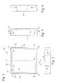
- FIG. 1is a front elevation view of a single filter frame in accordance with an exemplary but nonlimiting embodiment of the invention
- FIG. 2is a bottom plan view of the filter frame shown in FIG. 1 ;
- FIG. 3is a cross section taken along the line 3 - 3 of FIG. 1 ;
- FIG. 4is a side elevation of the frame shown in FIG. 1 ;
- FIG. 5is a cross section taken along the line 5 - 5 of FIG. 1 , but with a filter in place and a cam lock lever installed;
- FIG. 6is a partial section with the filter frame of FIG. 5 turned ninety degrees and showing the cam lock lever in locked and unlocked (in phantom) positions;
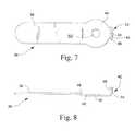
- FIG. 7is a side view of a cam lock lever in accordance with an exemplary but nonlimiting embodiment of the invention.
- FIG. 8is an edge view of the cam lock lever shown in FIG. 7 ;
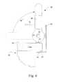
- FIG. 9is a cross section similar to FIG. 5 but showing a further exemplary embodiment where back-to-back cam lock levers are used to clamp adjacent filters within a multi-filter frame assembly;
- FIG. 10is a cross section similar to FIG. 5 but showing a further exemplary embodiment where two filters are stacked in tandem within frame, and clamped by a pair of cam lock levers oriented at ninety degrees relative to each other;
- FIG. 11is a partial perspective view of the stacked filter arrangement shown in FIG. 10 ;
- FIG. 12is a partial cross section showing an alternative pivot mount arrangement for a cam lock lever
- FIG. 13is a side elevation showing a tool used to swage the pivot pin shown in FIG. 12 ;
- FIGS. 14A and 14Bare section and side elevation views, respectively, showing an operating handle or tool for use with the cam lock lever shown in the various Figs.
- a filter holding frame 10 in an exemplary but non-limiting embodimentis substantially square in shape with two pair of substantially parallel side walls 12 , 14 , 16 and 18 .
- horizontal support flanges 20 , 22 , 24 and 26are provided for supporting a substantially planar and substantially square filter as described further herein.
- Opposed side walls 14 and 18are each provided with a pair of holes 28
- side walls 12 and 16are each provided with a pair of holes or apertures 30 .
- holes 28are located approximately 73 mm from the lower edge of the walls while holes 30 are located at approximately 43 mm above the lower edge of the walls.
- the frame as shownis designed to hold a single filter, or a pair of filters stacked in tandem.
- in holes 28 and 30support cam-locking devices at different elevations relative to the support flanges 20 , 22 , 24 and 26 as described further herein.
- the locations of the holesmay vary, of course, depending on specific applications.
- FIG. 5illustrates a portion of a substantially-square filter 32 having a resilient gasket 34 applied about the lower peripheral edge of the filter.
- the filteris supported on the lower horizontal support flanges 20 , 22 , 24 and 26 of the filter holding frame 10 .
- FIG. 5also illustrates a cam lock lever 36 mounted by way of a pivot pin 35 in one of the holes 30 of the filter holding frame 10 .
- the cam lock lever 36comprises an elongated handle portion 38 at one end and a substantially-circular cam head 40 at an opposite end.
- the cam head 40mounts (or is formed with) a laterally-extending cam foot 42 that is generally aligned along the longitudinal axis of the lever 36 .
- the cam foot 42is formed to include a lateral extension 44 which is located axially beyond the radiused surface of the cam head 40 via tab 45 , and is provided on one or both ends with a chamfered or upturned edge 46 , the purpose for which will be described later herein.
- a mounting hole or aperture 50Centrally-located within the cam head 40 , there is a mounting hole or aperture 50 also aligned along the longitudinal axis of the lever.
- the aperture 50is adapted to receive the pivot pin 35 illustrated in FIG. 5 by which the cam lock lever 36 is rotatably mounted to the frame 10 via hole 30 .
- the location of the holes 30 in the holding frame side walls 12 and 16is selected such that the cam lock levers 36 can move between open and clamped positions where, in the open position, the cam foot 42 may lightly engage, for example, the holding frame side wall 16 as shown in FIG. 6 , and when rotated 90 degrees to the clamped position, the cam foot 42 will engage the upper surface 52 of the filter 32 with the chamfered or upturned edge 46 providing a smooth engagement with the filter in the direction of rotation of the lever 38 , and then compress the filter 32 and the gasket 34 against the horizontal support flange 20 to thereby clamp and seal one corner of the filter 32 in place within the holding frame.
- cam lock lever 36is formed with an offset 48 which, at best appreciated from FIG. 5 , provides space between the holding frame side wall 12 and the handle portion 38 to reduce friction and to facilitate gripping and rotation of the handle portion 38 . It will be understood that cam-lock levers 36 may be installed in each of the four corners of the filter, utilizing the four mounting holes 30 as arranged in FIG. 1-4 .
- a filter-holding frame assemblyincludes adjacent filter-holding frames 10 , 110 , formed in part by a double-thickness, common side wall 112 .
- a second cam lock lever 136may be installed with the first lever 36 but on the opposite side of the side wall 112 .
- An extended pivot pin 35enables assembly of the double cam lock lever.
- one double-cam lock devicecan be used to independently clamp two adjacent filters 32 , 132 and their respective gaskets 34 , 134 on adjacent support surfaces 20 , 120 in the adjacent holding frames 10 , 110 .
- the filter-holding frame assemblymay be enlarged to include, for example, a planar grid that includes one or more groups of four mutually adjacent filter frames where four side walls converge at an intersection defining four corner quadrants, respectively, of four mutually adjacent frames.
- Each of the four intersecting side wallsis common to two of the four mutually adjacent frames.
- one, two or all four of the side wallsmay be provided with a double-cam lock lever device as described above, proximate the intersection. This arrangement may be repeated throughout the grid as desired.
- FIG. 12An alternative pivot pin construction particularly useful in the multi-cam lock lever arrangement of FIG. 9 is shown in FIG. 12 .
- the pivot pin 52includes a first pin component 54 that is received within a second pin component 56 .
- the pivot pin assemblyis installed from opposite sides of the holding frame wall, and a tool 60 is then used to swage the hollow end of the first pin component 54 radially outwardly into locking engagement with a beveled edge 62 of the second pin component 56 to thereby permanently secure the cam lock lever 36 to the holding-frame wall.
- a pair of filters 32 , 232may be stacked in tandem when a single holding frame 10 in which case, additional cam lock levers 64 , 164 may be secured by means of the vertically-spaced holes 28 on the holding frame side walls 14 , 18 and utilized to clamp the second or stacked filter 232 in substantially the same manner as described above. It will be appreciated that the cam lock levers mounted in the holes 30 extend substantially 90 degrees relative to the cam lock levers mounted in the holes 28 .
- cam lock leversmay be used to clamp the corners of the lower or downstream filter 32 and four cam lock devices may be used to clamp the corners of the upper or upstream filter 232 but arranged at a 90 degree angle relative to the cam lock levers clamping the lower filter.
- This arrangementallows the upper or upstream filters 232 to be removed from the filter holding frame while the underlying lower or downstream filter 32 remains clamped and sealed within the holding frame. This is important in that any particles dislodged due to removal/replacement of the upstream filter will not pass the downstream filter and, by keeping the downstream filter clamped and sealed, no dislodgement of any particles occurs at the downstream filter.
- the stacked filters 32 , 132are shown in one of four partially shown mutually perpendicular filter frames. It will be appreciated that double-cam lock lever devices may be employed here as well to conveniently lock the filters in the respective adjacent frames, with a double-cam lock lever secured to each of the four intersecting holding frame side walls as described above.
- cam lock levers and the holding frame side wallsbe provided with cooperating projections and detents to prevent accidental movement of the cam lock levers from either the open or closed (i.e., clamped) position. More specifically, detents 66 ( FIG. 11 ) are provided in the holding frame side walls where they are engaged by projections 68 stamped or otherwise formed in the cam lock levers 32 , 232 in both the open and closed (or clamped) positions. Other substantially equivalent means for providing the retention or locking function may be employed as well.
- FIG. 13illustrates a tool stand assembly 70 employed to support the tool 60 used to deform the pivot pin assembly 52 shown in FIG. 12 .
- the tool 60may be adjusted along vertical and horizontal shafts 72 , 74 to locate the tool 60 as needed.
- the frame 112is held in a U-shaped support frame 76 . Note that in this view, the individual cam-lock levers are only partially shown.
- a cam lock lever operating handle or tool 78may be slidably attached to the distal end of the elongated handle portion 38 cam lock lever 36 to facilitate rotation.
- the tool 78is comprised of a hollow sleeve that includes a first portion 80 that is substantially coaxial with the handle portion 38 and an angled portion 82 that extends angularly away from the first portion 80 .
- the angled portion 82provides a more convenient gripping surface for the user as the cam lock lever is rotated between its open and closed (or clamped) positions.
Landscapes
- Chemical & Material Sciences (AREA)
- Engineering & Computer Science (AREA)
- Chemical Kinetics & Catalysis (AREA)
- Combustion & Propulsion (AREA)
- Mechanical Engineering (AREA)
- General Engineering & Computer Science (AREA)
- Filtering Of Dispersed Particles In Gases (AREA)
Abstract
Description
Claims (20)
Priority Applications (4)
| Application Number | Priority Date | Filing Date | Title |
|---|---|---|---|
| US12/880,496US8273145B2 (en) | 2010-09-13 | 2010-09-13 | Cam-type locking device for retaining static filter panels in a filter holding frame |
| KR1020110091023AKR20120028246A (en) | 2010-09-13 | 2011-09-08 | Cam-type locking device for retaining static filter panels in a filter holding frame |
| CN2011102836103ACN102397730A (en) | 2010-09-13 | 2011-09-09 | Cam-type locking device for retaining static filter panels in a filter holding frame |
| JP2011197909AJP2012055884A (en) | 2010-09-13 | 2011-09-12 | Cam-type locking device for retaining static filter panel in filter holding frame |
Applications Claiming Priority (1)
| Application Number | Priority Date | Filing Date | Title |
|---|---|---|---|
| US12/880,496US8273145B2 (en) | 2010-09-13 | 2010-09-13 | Cam-type locking device for retaining static filter panels in a filter holding frame |
Publications (2)
| Publication Number | Publication Date |
|---|---|
| US20120060454A1 US20120060454A1 (en) | 2012-03-15 |
| US8273145B2true US8273145B2 (en) | 2012-09-25 |
Family
ID=45805308
Family Applications (1)
| Application Number | Title | Priority Date | Filing Date |
|---|---|---|---|
| US12/880,496Expired - Fee RelatedUS8273145B2 (en) | 2010-09-13 | 2010-09-13 | Cam-type locking device for retaining static filter panels in a filter holding frame |
Country Status (4)
| Country | Link |
|---|---|
| US (1) | US8273145B2 (en) |
| JP (1) | JP2012055884A (en) |
| KR (1) | KR20120028246A (en) |
| CN (1) | CN102397730A (en) |
Cited By (6)
| Publication number | Priority date | Publication date | Assignee | Title |
|---|---|---|---|---|
| US20130180221A1 (en)* | 2005-09-09 | 2013-07-18 | Dexwet Usa Llc | Filter module |
| US9297199B2 (en) | 2013-05-31 | 2016-03-29 | Houston Shutters, LLC | Frame with fasteners securing aligned members and methods for forming same |
| US10864469B2 (en) | 2017-06-05 | 2020-12-15 | Donaldson Company, Inc. | Air cleaner assemblies and methods of use |
| US11235274B2 (en) | 2011-06-30 | 2022-02-01 | Donaldson Company, Inc. | Filter systems; components; features; and, methods of assembly and use |
| US11318405B2 (en) | 2016-06-17 | 2022-05-03 | Donaldson Company, Inc. | Air cleaner assemblies and methods of use |
| US20230220694A1 (en)* | 2022-01-07 | 2023-07-13 | Blue Square Manufacturing, Llc | Skimmer and Basket Assembly |
Families Citing this family (18)
| Publication number | Priority date | Publication date | Assignee | Title |
|---|---|---|---|---|
| US8551206B2 (en)* | 2011-05-18 | 2013-10-08 | General Electric Company | System and method for securing gas turbine air filters |
| CN102872923A (en)* | 2012-10-16 | 2013-01-16 | 立德泰勀(上海)科学仪器有限公司 | Biosafety cabinet provided with easily-assembled and disassembled filters |
| US20150101344A1 (en)* | 2013-10-15 | 2015-04-16 | Bha Altair, Llc | Systems and Methods for Bypassing a Coalescer in a Gas Turbine Inlet |
| JP2015192947A (en) | 2014-03-31 | 2015-11-05 | キヤノン株式会社 | Dust collection filter |
| US10226727B2 (en)* | 2014-06-03 | 2019-03-12 | Cummins Filtration Ip, Inc. | Filter assembly with cam-lock filter interface |
| EP3189283B1 (en)* | 2014-09-04 | 2022-03-02 | Camfil AB | Filter housing |
| US10213719B2 (en) | 2014-10-03 | 2019-02-26 | Westinghouse Air Brake Technologies Corporation | Cam lock system for reciprocating air compressor inlet filter |
| CN105056656B (en)* | 2015-09-07 | 2017-03-22 | 珠海格力电器股份有限公司 | Fixed frame and filter |
| JP6654848B2 (en)* | 2015-10-08 | 2020-02-26 | ニッタ株式会社 | Insect repellent casing of air filter |
| JP7086970B2 (en)* | 2017-02-21 | 2022-06-20 | ゼネラル・エレクトリック・カンパニイ | A system that reduces start-up emissions of power plants, including gas turbines |
| US10434449B1 (en) | 2017-07-26 | 2019-10-08 | Alan Coupal | Filter retaining mechanism with filter/pre-filter clip |
| EP3599006A1 (en)* | 2018-07-24 | 2020-01-29 | Industrilås I Nässjö AB | Filter lock |
| US11351493B2 (en)* | 2019-02-27 | 2022-06-07 | Johnson Controls Tyco IP Holdings LLP | Adjustable filter track for HVAC system |
| CN113266943B (en) | 2020-02-14 | 2022-09-02 | 约克广州空调冷冻设备有限公司 | Filter fixing device and air conditioning unit using same |
| KR102813201B1 (en)* | 2020-04-21 | 2025-05-28 | 삼성전자주식회사 | Air cleaner having filter assembly unit |
| CN113617142B (en)* | 2020-05-07 | 2023-04-18 | 钰祥企业股份有限公司 | Filtering module |
| JP7690367B2 (en)* | 2021-09-30 | 2025-06-10 | 日本無機株式会社 | Filter casing and filter housing |
| WO2024238799A1 (en)* | 2023-05-18 | 2024-11-21 | Donaldson Company, Inc. | Stacked filter arrangement |
Citations (2)
| Publication number | Priority date | Publication date | Assignee | Title |
|---|---|---|---|---|
| US7540073B1 (en) | 2006-06-27 | 2009-06-02 | Braden Manufacturing, L.L.C. | Apparatus for clipping filter and coalescer elements on a frame |
| US20090158886A1 (en)* | 2006-01-23 | 2009-06-25 | O'connell Keiron | Front Access Frame Sealing Mechanism for Filter Cassettes |
Family Cites Families (8)
| Publication number | Priority date | Publication date | Assignee | Title |
|---|---|---|---|---|
| JPS5817616Y2 (en)* | 1979-03-26 | 1983-04-09 | 忍足 義見 | Air “filter” tightening device |
| JPS61291016A (en)* | 1985-06-18 | 1986-12-20 | Nitta Kk | Apparatus for mounting air filter element |
| JPH0326903Y2 (en)* | 1986-10-01 | 1991-06-11 | ||
| JPH0510901Y2 (en)* | 1988-01-25 | 1993-03-17 | ||
| CN2058619U (en)* | 1989-04-27 | 1990-06-27 | 上海华元干燥技术工程公司 | Turning-over tank filter with sealing cap |
| CN101402012A (en)* | 2008-09-01 | 2009-04-08 | 毛炳军 | Crystal cotton frameless pulse precipitation apparatus |
| US8105409B2 (en)* | 2009-01-30 | 2012-01-31 | General Electric Company | Filter retention system |
| CN201470262U (en)* | 2009-07-29 | 2010-05-19 | 康斐尔过滤设备(昆山)有限公司 | Connection structure of filter and box body |
- 2010
- 2010-09-13USUS12/880,496patent/US8273145B2/ennot_activeExpired - Fee Related
- 2011
- 2011-09-08KRKR1020110091023Apatent/KR20120028246A/ennot_activeWithdrawn
- 2011-09-09CNCN2011102836103Apatent/CN102397730A/enactivePending
- 2011-09-12JPJP2011197909Apatent/JP2012055884A/enactivePending
Patent Citations (3)
| Publication number | Priority date | Publication date | Assignee | Title |
|---|---|---|---|---|
| US20090158886A1 (en)* | 2006-01-23 | 2009-06-25 | O'connell Keiron | Front Access Frame Sealing Mechanism for Filter Cassettes |
| US8062401B2 (en)* | 2006-01-23 | 2011-11-22 | Aaf-Mcquay Inc. | Front access frame sealing mechanism for filter cassettes |
| US7540073B1 (en) | 2006-06-27 | 2009-06-02 | Braden Manufacturing, L.L.C. | Apparatus for clipping filter and coalescer elements on a frame |
Cited By (12)
| Publication number | Priority date | Publication date | Assignee | Title |
|---|---|---|---|---|
| US20130180221A1 (en)* | 2005-09-09 | 2013-07-18 | Dexwet Usa Llc | Filter module |
| US8986413B2 (en)* | 2005-09-09 | 2015-03-24 | Dexwet Usa Llc | Filter module |
| US11235274B2 (en) | 2011-06-30 | 2022-02-01 | Donaldson Company, Inc. | Filter systems; components; features; and, methods of assembly and use |
| US9297199B2 (en) | 2013-05-31 | 2016-03-29 | Houston Shutters, LLC | Frame with fasteners securing aligned members and methods for forming same |
| US9816309B2 (en) | 2013-05-31 | 2017-11-14 | Houston Shutters, LLC | Frame with fasteners securing aligned members and methods for forming same |
| US11318405B2 (en) | 2016-06-17 | 2022-05-03 | Donaldson Company, Inc. | Air cleaner assemblies and methods of use |
| US11951433B2 (en) | 2016-06-17 | 2024-04-09 | Donaldson Company, Inc. | Air cleaner assemblies and methods of use |
| US10864469B2 (en) | 2017-06-05 | 2020-12-15 | Donaldson Company, Inc. | Air cleaner assemblies and methods of use |
| US11684882B2 (en) | 2017-06-05 | 2023-06-27 | Donaldson Company, Inc. | Air cleaner assemblies and methods of use |
| US12214307B2 (en) | 2017-06-05 | 2025-02-04 | Donaldson Company, Inc. | Air cleaner assemblies and methods of use |
| US20230220694A1 (en)* | 2022-01-07 | 2023-07-13 | Blue Square Manufacturing, Llc | Skimmer and Basket Assembly |
| US12203287B2 (en)* | 2022-01-07 | 2025-01-21 | Blue Square Manufacturing, Llc | Pool skimmer assembly with securable skimmer basket facilitated by receivable engagement of the skimmer basket's handle with the skimmer housing and subsequent rotation of the handle |
Also Published As
| Publication number | Publication date |
|---|---|
| KR20120028246A (en) | 2012-03-22 |
| JP2012055884A (en) | 2012-03-22 |
| CN102397730A (en) | 2012-04-04 |
| US20120060454A1 (en) | 2012-03-15 |
Similar Documents
| Publication | Publication Date | Title |
|---|---|---|
| US8273145B2 (en) | Cam-type locking device for retaining static filter panels in a filter holding frame | |
| US10646807B2 (en) | Holding frame assembly and flexible retainers for same | |
| US10363507B2 (en) | Filter housing | |
| US8062402B2 (en) | Filter holding frame with clamping mechanism | |
| US20100192528A1 (en) | Filter retention system | |
| US7496993B2 (en) | Retention clip | |
| US8784528B2 (en) | Holding frame | |
| EP1887232A2 (en) | Cable mount | |
| AU2011201725B2 (en) | Self-centering ceiling panel | |
| US8683768B2 (en) | Ceiling panel clip | |
| US20190351840A1 (en) | Vehicle camera mounting interfaces | |
| US7540073B1 (en) | Apparatus for clipping filter and coalescer elements on a frame | |
| US20240082769A1 (en) | Cartridges for Vertically Oriented Dust Collectors | |
| US11400401B2 (en) | Filter device and filter system | |
| JP6739503B2 (en) | Bolt connector | |
| CZ2011538A3 (en) | Cam locking device for holding static filtration panels in a filter-holding frame | |
| EP4076700A1 (en) | Pleated filter element for air filter | |
| JP2011183281A (en) | Attachment mechanism of air filter |
Legal Events
| Date | Code | Title | Description |
|---|---|---|---|
| AS | Assignment | Owner name:GENERAL ELECTRIC COMPANY, NEW YORK Free format text:ASSIGNMENT OF ASSIGNORS INTEREST;ASSIGNORS:BANKS, STEPHEN FRANCIS;MCGUIGAN, PETER;REEL/FRAME:024976/0499 Effective date:20100913 | |
| AS | Assignment | Owner name:GENERAL ELECTRIC COMPANY, NEW YORK Free format text:ASSIGNMENT OF ASSIGNORS INTEREST;ASSIGNORS:BANKS, STEPHEN FRANCIS;MCGUIGAN, PETER;REEL/FRAME:026670/0785 Effective date:20110729 | |
| AS | Assignment | Owner name:GENERAL ELECTRIC COMPANY, NEW YORK Free format text:CORRECTIVE ASSIGNMENT TO CORRECT THE OMISSION OF THE TITLE ON THE ORIGINALLY-FILED ASSIGNMENT PREVIOUSLY RECORDED ON REEL 026670 FRAME 0785. ASSIGNOR(S) HEREBY CONFIRMS THE TITLE WAS INADVERTENTLY OMITTED;ASSIGNORS:BANKS, STEPHEN FRANCIS;MCGUIGAN, PETER;REEL/FRAME:026684/0249 Effective date:20110729 | |
| FEPP | Fee payment procedure | Free format text:PAYOR NUMBER ASSIGNED (ORIGINAL EVENT CODE: ASPN); ENTITY STATUS OF PATENT OWNER: LARGE ENTITY | |
| FEPP | Fee payment procedure | Free format text:PAYER NUMBER DE-ASSIGNED (ORIGINAL EVENT CODE: RMPN); ENTITY STATUS OF PATENT OWNER: LARGE ENTITY Free format text:PAYOR NUMBER ASSIGNED (ORIGINAL EVENT CODE: ASPN); ENTITY STATUS OF PATENT OWNER: LARGE ENTITY | |
| AS | Assignment | Owner name:BHA ALTAIR, LLC, TENNESSEE Free format text:ASSIGNMENT OF ASSIGNORS INTEREST;ASSIGNORS:GENERAL ELECTRIC COMPANY;BHA GROUP, INC.;ALTAIR FILTER TECHNOLOGY LIMITED;REEL/FRAME:031911/0797 Effective date:20131216 | |
| REMI | Maintenance fee reminder mailed | ||
| LAPS | Lapse for failure to pay maintenance fees | ||
| STCH | Information on status: patent discontinuation | Free format text:PATENT EXPIRED DUE TO NONPAYMENT OF MAINTENANCE FEES UNDER 37 CFR 1.362 | |
| FP | Lapsed due to failure to pay maintenance fee | Effective date:20160925 |