US8273135B2 - Method of manufacturing solid electrolytic capacitor - Google Patents
Method of manufacturing solid electrolytic capacitorDownload PDFInfo
- Publication number
- US8273135B2 US8273135B2US12/574,276US57427609AUS8273135B2US 8273135 B2US8273135 B2US 8273135B2US 57427609 AUS57427609 AUS 57427609AUS 8273135 B2US8273135 B2US 8273135B2
- Authority
- US
- United States
- Prior art keywords
- polymerization liquid
- silane compound
- oxidant
- solid electrolytic
- monomer
- Prior art date
- Legal status (The legal status is an assumption and is not a legal conclusion. Google has not performed a legal analysis and makes no representation as to the accuracy of the status listed.)
- Active, expires
Links
Images


Classifications
- H—ELECTRICITY
- H01—ELECTRIC ELEMENTS
- H01G—CAPACITORS; CAPACITORS, RECTIFIERS, DETECTORS, SWITCHING DEVICES, LIGHT-SENSITIVE OR TEMPERATURE-SENSITIVE DEVICES OF THE ELECTROLYTIC TYPE
- H01G9/00—Electrolytic capacitors, rectifiers, detectors, switching devices, light-sensitive or temperature-sensitive devices; Processes of their manufacture
- H01G9/0029—Processes of manufacture
- H01G9/0036—Formation of the solid electrolyte layer
- H—ELECTRICITY
- H01—ELECTRIC ELEMENTS
- H01G—CAPACITORS; CAPACITORS, RECTIFIERS, DETECTORS, SWITCHING DEVICES, LIGHT-SENSITIVE OR TEMPERATURE-SENSITIVE DEVICES OF THE ELECTROLYTIC TYPE
- H01G9/00—Electrolytic capacitors, rectifiers, detectors, switching devices, light-sensitive or temperature-sensitive devices; Processes of their manufacture
- H01G9/004—Details
- H01G9/008—Terminals
- H01G9/012—Terminals specially adapted for solid capacitors
- H—ELECTRICITY
- H01—ELECTRIC ELEMENTS
- H01G—CAPACITORS; CAPACITORS, RECTIFIERS, DETECTORS, SWITCHING DEVICES, LIGHT-SENSITIVE OR TEMPERATURE-SENSITIVE DEVICES OF THE ELECTROLYTIC TYPE
- H01G11/00—Hybrid capacitors, i.e. capacitors having different positive and negative electrodes; Electric double-layer [EDL] capacitors; Processes for the manufacture thereof or of parts thereof
- H01G11/54—Electrolytes
- H01G11/56—Solid electrolytes, e.g. gels; Additives therein
- H—ELECTRICITY
- H01—ELECTRIC ELEMENTS
- H01G—CAPACITORS; CAPACITORS, RECTIFIERS, DETECTORS, SWITCHING DEVICES, LIGHT-SENSITIVE OR TEMPERATURE-SENSITIVE DEVICES OF THE ELECTROLYTIC TYPE
- H01G9/00—Electrolytic capacitors, rectifiers, detectors, switching devices, light-sensitive or temperature-sensitive devices; Processes of their manufacture
- H01G9/004—Details
- H01G9/022—Electrolytes; Absorbents
- H01G9/025—Solid electrolytes
- H01G9/028—Organic semiconducting electrolytes, e.g. TCNQ
- H—ELECTRICITY
- H01—ELECTRIC ELEMENTS
- H01G—CAPACITORS; CAPACITORS, RECTIFIERS, DETECTORS, SWITCHING DEVICES, LIGHT-SENSITIVE OR TEMPERATURE-SENSITIVE DEVICES OF THE ELECTROLYTIC TYPE
- H01G9/00—Electrolytic capacitors, rectifiers, detectors, switching devices, light-sensitive or temperature-sensitive devices; Processes of their manufacture
- H01G9/15—Solid electrolytic capacitors
- Y—GENERAL TAGGING OF NEW TECHNOLOGICAL DEVELOPMENTS; GENERAL TAGGING OF CROSS-SECTIONAL TECHNOLOGIES SPANNING OVER SEVERAL SECTIONS OF THE IPC; TECHNICAL SUBJECTS COVERED BY FORMER USPC CROSS-REFERENCE ART COLLECTIONS [XRACs] AND DIGESTS
- Y02—TECHNOLOGIES OR APPLICATIONS FOR MITIGATION OR ADAPTATION AGAINST CLIMATE CHANGE
- Y02E—REDUCTION OF GREENHOUSE GAS [GHG] EMISSIONS, RELATED TO ENERGY GENERATION, TRANSMISSION OR DISTRIBUTION
- Y02E60/00—Enabling technologies; Technologies with a potential or indirect contribution to GHG emissions mitigation
- Y02E60/13—Energy storage using capacitors
- Y—GENERAL TAGGING OF NEW TECHNOLOGICAL DEVELOPMENTS; GENERAL TAGGING OF CROSS-SECTIONAL TECHNOLOGIES SPANNING OVER SEVERAL SECTIONS OF THE IPC; TECHNICAL SUBJECTS COVERED BY FORMER USPC CROSS-REFERENCE ART COLLECTIONS [XRACs] AND DIGESTS
- Y10—TECHNICAL SUBJECTS COVERED BY FORMER USPC
- Y10T—TECHNICAL SUBJECTS COVERED BY FORMER US CLASSIFICATION
- Y10T29/00—Metal working
- Y10T29/49—Method of mechanical manufacture
- Y10T29/49002—Electrical device making
- Y10T29/49117—Conductor or circuit manufacturing
Definitions
- the present inventionrelates to a method of manufacturing a solid electrolytic capacitor.
- FIGS. 1 and 2Japanese Patent Laying-Open No. 10-144574.
- a solid electrolytic capacitor 1has a capacitor element 6 having leads 8 A and 8 B, a bottomed case 9 accommodating capacitor element 6 , and a sealing member 10 sealing capacitor element 6 .
- the vicinity of an opening end of bottomed case 9is subjected to pressing in a lateral direction and curling.
- capacitor element 6is formed by winding an anode body 2 having a dielectric coating film formed on a surface thereof and a cathode body 3 together, with a separator 12 being interposed therebetween, and thereafter securing the wound object with a winding stop tape 5 ,
- Anode lead 8 Ais connected with anode body 2 through an anode lead tab 7 A
- cathode lead 8 Bis connected with cathode body 3 through a cathode lead tab 7 B.
- an electrolyte of solid electrolytic capacitor 1 with a configuration as described abovefor example, a solid electrolyte made of a conductive polymer is used. Such an electrolyte is charged into a gap between anode body 2 and cathode body 3 as electrode foils of capacitor element 6 .
- ESRrefers to an equivalent series resistance
- examples of a method of causing a solid electrolytic capacitor to have a high voltage proof propertyincludes a method of causing a dielectric coating film formed on a surface of an anode body to have a high voltage proof property by increasing chemical conversion voltage applied during chemical conversion treatment for forming the dielectric coating film.
- the chemical conversion voltageis increased, there occur problems such as increase of leak current due to degradation in leak current property, occurrence of a short circuit, and the like.
- One object of the present inventionis to provide a method of manufacturing a solid electrolytic capacitor using a conductive polymer as a solid electrolyte, in which increase of leak current and occurrence of a short circuit are suppressed, and which has a high voltage proof property.
- a first aspect of the present inventionis a method of manufacturing a solid electrolytic capacitor including a capacitor element, the capacitor element having an anode body with a dielectric coating film formed on a surface thereof and a solid electrolyte made of a conductive polymer, the method including the steps of: forming the capacitor element having the anode body with the dielectric coating film formed on the surface thereof; preparing a polymerization liquid A containing a monomer as a precursor of the conductive polymer and a silane compound; preparing a polymerization liquid B by adding an oxidant to polymerization liquid A; and performing polymerization after impregnating the capacitor element with polymerization liquid B.
- a second aspect of the present inventionis a method of manufacturing a solid electrolytic capacitor including a capacitor element, the capacitor element having an anode body with a dielectric coating film formed on a surface thereof and a solid electrolyte made of a conductive polymer, the method including the steps of: forming the capacitor element having the anode body with the dielectric coating film formed on the surface thereof; preparing a polymerization liquid A containing an oxidant and a silane compound; preparing a polymerization liquid B by adding a monomer as a precursor of the conductive polymer to polymerization liquid A; and performing polymerization after impregnating the capacitor element with polymerization liquid B.
- the silane compoundhas a concentration of 5 to 20 wt % relative to a total weight of the monomer as the precursor of the conductive polymer, the oxidant, and the silane compound.
- polymerization liquid Bis prepared when polymerization liquid A has a temperature of 5 to 40° C.
- a solid electrolytic capacitor using a conductive polymer as a solid electrolytein which increase of leak current and occurrence of a short circuit are suppressed, and which has a high voltage proof property and high reliability can be provided.
- FIG. 1is a cross sectional view of a typical solid electrolytic capacitor.
- FIG. 2is a perspective view of a capacitor element in the typical solid electrolytic capacitor.
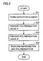
- FIG. 3is a flowchart showing a manufacturing process of the present invention.
- solid electrolytic capacitor 1includes capacitor element 6 , lead tabs 7 A and 7 B, leads 8 A and 8 B, bottomed case 9 , sealing member 10 , and a seat plate 11 .
- Leads 8 A and 8 Bare connected to capacitor element 6 through lead tabs 7 A and 7 B, respectively.
- Capacitor element 6is accommodated in bottomed case 9 such that a surface thereof onto which lead tabs 7 A and 7 B are connected is disposed at an opening end portion of bottomed case 9 .
- Capacitor element 6is sealed by disposing sealing member 10 at the opening end portion of bottomed case 9 .
- capacitor element 6includes anode body 2 connected with anode lead tab 7 A, cathode body 3 connected with cathode lead tab 7 B, and separator 12 .
- a dielectric coating filmis formed on a surface of anode body 2 .
- a dielectric coating filmmay also be formed on a surface of cathode body 3 , as with anode body 2 .
- a solid electrolyte layer made of a conductive polymeris formed in capacitor element 6 .
- the solid electrolyte layeris formed by chemically polymerizing a monomer in a solution containing the monomer, an oxidant, and a silane compound.
- the formed solid electrolyte layerhas a configuration in which the silane compound is contained in the conductive polymer.
- the silane compoundhas functions of improving molecular weight distribution and crystallinity of the conductive polymer, and strengthening binding of a conductive polymer chain by a cross-linking effect. As a result, leak current property and voltage proof property of the solid electrolytic capacitor are improved.
- capacitor element 6is formed (step S 31 ).
- the outer shape of capacitor element 6can be formed using a conventional method. Thereby, the capacitor element including anode body 2 having a dielectric coating film formed thereon, cathode body 3 , and lead tabs 7 A and 7 B connected to electrode bodies 2 and 3 , respectively, is formed.
- a polymerization liquid Ais prepared by mixing one of a monomer and an oxidant with a silane compound (step S 32 ). Then, a polymerization liquid B is prepared by adding the other (i.e., the other of the monomer and the oxidant that is not contained in polymerization liquid A) to polymerization liquid A (step S 33 ).
- polymerization liquid Aby mixing one of the monomer and the oxidant with the silane compound beforehand, and thereafter prepare polymerization liquid B by adding the other (i.e., the other of the monomer and the oxidant that is not contained in polymerization liquid A) to polymerization liquid A, as described above.
- the otheri.e., the other of the monomer and the oxidant that is not contained in polymerization liquid A
- polymerization liquid Asince the temperature of polymerization liquid A is increased by the heat of reaction after the preparation thereof, it is preferable to prepare polymerization liquid B using polymerization liquid A after the temperature of polymerization liquid A is stabilized at 5 to 40° C. If polymerization liquid A having a temperature of less than 5° C. is used, moisture incorporation due to condensation and solvent solidification may occur, and if polymerization liquid A having a temperature of more than 40° C. is used, the polymerization reaction in step S 33 may not be stabilized.
- silane compound used in the present inventionvinyltrichlorosilane, vinyltrimethoxysilane, vinyltriethoxysilane, ⁇ -(3,4-epoxy-cyclohexyl) ethyltrimethoxysilane, ⁇ -glycidoxypropyltrimethoxysilane, ⁇ -glycidoxypropyltriethoxysilane, ⁇ -methacryloxypropyltrimethoxysilane, ⁇ -glycidoxypropylmethyldiethoxysilane, p-styryltrimethoxysilane, ⁇ -methacryloxypropylmethyldimethoxysilane, ⁇ -methacryloxypropylmethyldiethoxysilane, ⁇ -methacryloxypropyltriethoxysilane, ⁇ -acryloxypropyltrimethoxysilane, N-2-(aminoethyl) ⁇ -aminopropylmethyldimethoxysilane,
- ⁇ -(3,4-epoxy-cyclohexyl)ethyltrimethoxysilane⁇ -acryloxypropyltrimethoxysilane, ⁇ -glycidoxypropyltrimethoxysilane, ⁇ -methacryloxypropyltrimethoxysilane, ⁇ -glycidoxypropylmethyldiethoxysilane, or ⁇ -glycidoxypropyltriethoxysilane is more preferable.
- two or more of the silane compoundsmay be combined and used.
- the silane compound contained in the conductive polymerhas a concentration of 5 to 20 wt %, when a total weight of the monomer, the oxidant, and the silane compound is represented as 100 wt %. Since the influence of the heat of reaction caused by addition of the silane compound is extremely reduced in the method of preparing the polymerization liquid of the present invention, the silane compound can be used in large amount. By increasing the concentration of the silane compound in the conductive polymer, leak current property and voltage proof property of the solid electrolytic capacitor can be improved.
- the conductive polymer that can be used in the present inventionpreferably contains at least one or more conductive polymers of the aliphatic series, the aromatic series, the heterocyclic series, and the heteroatom-containing series.
- a polythiophene, polyaniline, or polypyrrole conductive polymeris preferable.
- oxidanta conventionally known oxidant compound including ferric p-toluenesulfonic acid, or an oxidant solution prepared by dissolving the oxidant compound in alcohol such as ethanol, butanol, or the like can be used.
- alcoholsuch as ethanol, butanol, or the like
- an oxidant solutionit is preferable to prepare the oxidant solution such that an oxidant compound in the oxidant solution has a concentration of 35 to 70 wt %.
- capacitor element 6is impregnated with polymerization liquid B prepared as described above, chemical polymerization is performed (step S 34 ) to form a solid electrolyte in capacitor element 6 .
- polymerization liquid Bmay be applied to capacitor element 6 .
- Capacitor element 6 fabricated as described aboveis accommodated in bottomed case 9 , and the opening end portion of bottomed case 9 is sealed with sealing member 10 to complete solid electrolytic capacitor 1 .
- etching treatmentwas performed on surfaces of anode body 2 and cathode body 3 made of aluminum foil. Thereafter, a dielectric coating film was formed on the surface of anode body 2 by immersing anode body 2 subjected to etching treatment in a chemical conversion solution and applying a voltage of 150 V.
- Anode lead tab 7 A and cathode lead tab 7 Bwere connected to anode body 2 and cathode body 3 , respectively. Then, anode body 2 and cathode body 3 were wound together with separator 12 , and the outermost periphery was secured with winding stop tape 5 to fabricate capacitor element 6 .
- capacitor element 6was subjected to chemical conversion treatment of a cut section.
- Chemical conversion treatment of a cut sectionwas performed by immersing capacitor element 6 in a chemical conversion solution and applying voltage.
- a polymerization liquid for a conductive polymer as a solid electrolytewas prepared.
- a monomer3,4-ethylenedioxythiophene was used.
- an oxidanta butanol solution of ferric p-toluenesulfonic acid was used.
- a silane compound⁇ -acryloxypropyltrimethoxysilane was used. Weight percentages of ferric p-toluenesulfonic acid and butanol in the oxidant were set to 40 wt % and 60 wt %, respectively. Weight percentages of the monomer, the oxidant, and the silane compound in the polymerization liquid were set to 25 wt %, 74 wt %, and 1 wt %, respectively.
- polymerization liquid Awas prepared by mixing ferric p-toluenesulfonic acid and ⁇ -acryloxypropyltrimethoxysilane. Thereafter, polymerization liquid B was prepared by adding 3,4-ethylenedioxythiophene to polymerization liquid A.
- capacitor element 6was impregnated with polymerization liquid B and subjected to thermochemical polymerization to form a solid electrolyte layer made of a conductive polymer inside capacitor element 6 .
- capacitor element 6was accommodated in bottomed case 9 , and sealing member 10 was inserted into the opening end portion of bottomed case 9 , which was then subjected to pressing in a lateral direction and curling. Then, seat plate 11 was provided on a curled surface, and leads 8 A and 8 B were pressed and bent to fabricate solid electrolytic capacitor 1 .
- a solid electrolytic capacitorwas fabricated as in Example 1 except for setting the weight percentages of the monomer, the oxidant, and the silane compound to 25 wt %, 72 wt %, and 3 wt %, respectively.
- a solid electrolytic capacitorwas fabricated as in Example 1 except for setting the weight percentages of the monomer, the oxidant, and the silane compound to 25 wt %, 70 wt %, and 5 wt %, respectively.
- a solid electrolytic capacitorwas fabricated as in Example 1 except for setting the weight percentages of the monomer, the oxidant, and the silane compound to 25 wt %, 65 wt %, and 10 wt %, respectively.
- a solid electrolytic capacitorwas fabricated as in Example 1 except for setting the weight percentages of the monomer, the oxidant, and the silane compound to 25 wt %, 60 wt %, and 15 wt %, respectively.
- a solid electrolytic capacitorwas fabricated as in Example 1 except for setting the weight percentages of the monomer, the oxidant, and the silane compound to 25 wt %, 55 wt %, and 20 wt %, respectively.
- a solid electrolytic capacitorwas fabricated as in Example 1 except for setting the weight percentages of the monomer, the oxidant, and the silane compound to 25 wt %, 50 wt %, and 25 wt %, respectively.
- a solid electrolytic capacitorwas fabricated as in Example 1 except for using ⁇ -glycidoxypropyltrimethoxysilane as the silane compound.
- a solid electrolytic capacitorwas fabricated as in Example 2 except for using ⁇ -glycidoxypropyltrimethoxysilane as the silane compound.
- a solid electrolytic capacitorwas fabricated as in Example 3 except for using ⁇ -glycidoxypropyltrimethoxysilane as the silane compound.
- a solid electrolytic capacitorwas fabricated as in Example 4 except for using ⁇ -glycidoxypropyltrimethoxysilane as the silane compound.
- a solid electrolytic capacitorwas fabricated as in Example 5 except for using ⁇ -glycidoxypropyltrimethoxysilane as the silane compound.
- a solid electrolytic capacitorwas fabricated as in Example 6 except for using ⁇ -glycidoxypropyltrimethoxysilane as the silane compound.
- a solid electrolytic capacitorwas fabricated as in Example 7 except for using ⁇ -glycidoxypropyltrimethoxysilane as the silane compound.
- a solid electrolytic capacitorwas fabricated as in Example 1 except for setting the weight percentages of the monomer, the oxidant, and the silane compound to 24 wt %, 75 wt %, and 1 wt %, respectively, and preparing the polymerization liquid by firstly preparing polymerization liquid A by mixing 3,4-ethylenedioxythiophene and ⁇ -acryloxypropyltrimethoxysilane, and then preparing polymerization liquid B by adding ferric p-toluenesulfonic acid to polymerization liquid A.
- a solid electrolytic capacitorwas fabricated as in Example 15 except for setting the weight percentages of the monomer, the oxidant, and the silane compound to 20 wt %, 75 wt %, and 5 wt %, respectively.
- a solid electrolytic capacitorwas fabricated as in Example 15 except for setting the weight percentages of the monomer, the oxidant, and the silane compound to 15 wt %, 75 wt %, and 10 wt %, respectively.
- a solid electrolytic capacitorwas fabricated as in Example 15 except for setting the weight percentages of the monomer, the oxidant, and the silane compound to 5 wt %, 75 wt %, and 20 wt %, respectively.
- a solid electrolytic capacitorwas fabricated as in Example 1 except for not preparing polymerization liquid A, setting the weight percentages of the monomer and the oxidant to 25 wt % and 75 wt %, respectively, and using a mixed solution prepared by mixing 3,4-ethylenedioxythiophene and ferric p-toluenesulfonic acid, as polymerization liquid B.
- a solid electrolytic capacitorwas fabricated as in Example 3 except for not preparing polymerization liquid A, and using a mixed solution prepared by simultaneously mixing 3,4-ethylenedioxythiophene, ferric p-toluenesulfonic acid, and ⁇ -acryloxypropyltrimethoxysilane, as polymerization liquid B.
- a solid electrolytic capacitorwas fabricated as in Example 4 except for not preparing polymerization liquid A, and using a mixed solution prepared by simultaneously mixing 3,4-ethylenedioxythiophene, ferric p-toluenesulfonic acid, and ⁇ -acryloxypropyltrimethoxysilane, as polymerization liquid B.
- a solid electrolytic capacitorwas fabricated as in Example 6 except for not preparing polymerization liquid A, and using a mixed solution prepared by simultaneously mixing 3,4-ethylenedioxythiophene, ferric p-toluenesulfonic acid, and ⁇ -acryloxypropyltrimethoxysilane, as polymerization liquid B.
- Table 1shows a list of conditions for the polymerization liquids in the examples and the comparative examples described above. It is to be noted that 20 solid electrolytic capacitors were fabricated for each of the examples and the comparative examples.
- Table 2shows measurement results of electric properties indicating average values of 20 solid electrolytic capacitors for each of the examples and the comparative examples.
- the solid electrolytic capacitorshad a rated voltage of 35 V, a capacitance of 22 ⁇ F, and dimensions of 10 mm in diameter and 12 mm in height.
- the short circuit occurrence ratioindicates a short circuit occurrence ratio after performing aging treatment at 125° C. for five hours.
- the capacitance and the dielectric loss tangentwere measured at a frequency of 120 Hz, and the ESR was measured at a frequency of 100 kHz.
- the leak currentindicates a value obtained two minutes after application of the rated voltage.
- the BDV valueindicates a breakdown voltage for the solid electrolytic capacitor measured by applying voltage increased at a rate of 1 V/s to the solid electrolytic capacitor at room temperature.
- Example 122.3 24.9 2.3 26.2 8.9 59.3
- Example 29.6 25.4 2.4 27.1 4.3 63.5
- Example 31.8 25.3 2.6 27.3 0.5 67.1
- Example 40.5 25.5 2.8 28.2 0.9 70.9
- Example 50 25.4 3.2 30.5 0.3 72.3
- Example 60 25.1 3.7 35.2 0.4 75.4
- Example 70 25.5 5.5 99.6 0.1 80.2
- Example 821.3 25.4 2.5 27.0 10.2 60.4
- Example 910.5 25.1 2.3 27.2 3.5 62.2
- Example 101.5 25.2 2.7 27.9 1.1 66.9
- Example 110.5 25.4 2.7 28.6 0.5 71.2
- Example 120 25.2 3.1 31.2 0.4 72.1
- Example 130 25.2 3.9 34.2 0.2 74.7
- Example 140 25.4 6.2 109.1 0.2 82.8
- Example 140 25.4 6.2 109.1 0.2 82.8
- the polymerization liquidwas prepared by mixing one of the monomer and the oxidant with the silane compound beforehand, occurrence of a short circuit and increase of leak current were suppressed, and properties related to the capacitance, the ESR, and the BDV value were improved, in particular the property related to the ESR was significantly improved, when compared with the solid electrolytic capacitors of Comparative Examples 2 to 4 in which the polymerization liquid was prepared by simultaneously mixing the monomer, the oxidant, and the silane compound.
- the weight percentage of the silane compoundis preferably 5 to 20 wt % to satisfy all of the short circuit property, the leak current property, the ESR property, and the voltage proof property in a solid electrolytic capacitor.
- one embodiment of the present inventionis a winding type solid electrolytic capacitor, it may be a chip type solid electrolytic capacitor, or a multi-layered solid electrolytic capacitor having a plurality of stacked capacitor elements.
- a valve metalsuch as tantalum, niobium, titanium, or the like may be used for the anode body, other than aluminum.
Landscapes
- Engineering & Computer Science (AREA)
- Power Engineering (AREA)
- Chemical & Material Sciences (AREA)
- Chemical Kinetics & Catalysis (AREA)
- Electrochemistry (AREA)
- Microelectronics & Electronic Packaging (AREA)
- Manufacturing & Machinery (AREA)
- Polyoxymethylene Polymers And Polymers With Carbon-To-Carbon Bonds (AREA)
- Compositions Of Macromolecular Compounds (AREA)
- Addition Polymer Or Copolymer, Post-Treatments, Or Chemical Modifications (AREA)
Abstract
Description
| TABLE 1 | ||
| Weight Percentage (wt %) | ||
| Polymerization Liquid Preparation Method | Mono- | Oxi- | Silane |
| Silane Compound | Polymerization Liquid A | Polymerization Liquid B | mer | dant | Compound | ||
| Example 1 | γ-acryloxypropyltrimethoxysilane | Oxidant + Silane Compound | Polymerization Liquid A + Monomer | 25 | 74 | 1 |
| Example 2 | γ-acryloxypropyltrimethoxysilane | Oxidant + Silane Compound | Polymerization Liquid A + Monomer | 25 | 72 | 3 |
| Example 3 | γ-acryloxypropyltrimethoxysilane | Oxidant + Silane Compound | Polymerization Liquid A + Monomer | 25 | 70 | 5 |
| Example 4 | γ-acryloxypropyltrimethoxysilane | Oxidant + Silane Compound | Polymerization Liquid A + Monomer | 25 | 65 | 10 |
| Example 5 | γ-acryloxypropyltrimethoxysilane | Oxidant + Silane Compound | Polymerization Liquid A + Monomer | 25 | 60 | 15 |
| Example 6 | γ-acryloxypropyltrimethoxysilane | Oxidant + Silane Compound | Polymerization Liquid A + Monomer | 25 | 55 | 20 |
| Example 7 | γ-acryloxypropyltrimethoxysilane | Oxidant + Silane Compound | Polymerization Liquid A + Monomer | 25 | 50 | 25 |
| Example 8 | γ-glycidoxypropyltrimethoxysilane | Oxidant + Silane Compound | Polymerization Liquid A + Monomer | 25 | 74 | 1 |
| Example 9 | γ-glycidoxypropyltrimethoxysilane | Oxidant + Silane Compound | Polymerization Liquid A + Monomer | 25 | 72 | 3 |
| Example 10 | γ-glycidoxypropyltrimethoxysilane | Oxidant + Silane Compound | Polymerization Liquid A + Monomer | 25 | 70 | 5 |
| Example 11 | γ-glycidoxypropyltrimethoxysilane | Oxidant + Silane Compound | Polymerization Liquid A + Monomer | 25 | 65 | 10 |
| Example 12 | γ-glycidoxypropyltrimethoxysilane | Oxidant + Silane Compound | Polymerization Liquid A + Monomer | 25 | 60 | 15 |
| Example 13 | γ-glycidoxypropyltrimethoxysilane | Oxidant + Silane Compound | Polymerization Liquid A + Monomer | 25 | 55 | 20 |
| Example 14 | γ-glycidoxypropyltrimethoxysilane | Oxidant + Silane Compound | Polymerization Liquid A + Monomer | 25 | 50 | 25 |
| Example 15 | γ-acryloxypropyltrimethoxysilane | Monomer + Silane Compound | Polymerization Liquid A + Oxidant | 24 | 75 | 1 |
| Example 16 | γ-acryloxypropyltrimethoxysilane | Monomer + Silane Compound | Polymerization Liquid A + Oxidant | 20 | 75 | 5 |
| Example 17 | γ-acryloxypropyltrimethoxysilane | Monomer + Silane Compound | Polymerization Liquid A + Oxidant | 15 | 75 | 10 |
| Example 18 | γ-acryloxypropyltrimethoxysilane | Monomer + Silane Compound | Polymerization Liquid A + Oxidant | 5 | 75 | 20 |
| Comparative | — | — | Monomer + Oxidant | 25 | 75 | — |
| Example 1 | ||||||
| Comparative | γ-acryloxypropyltrimethoxysilane | — | Monomer + Oxidant + Silane | 25 | 70 | 5 |
| Example 2 | Compound | |||||
| Comparative | γ-acryloxypropyltrimethoxysilane | — | Monomer + Oxidant + Silane | 25 | 65 | 10 |
| Example 3 | Compound | |||||
| Comparative | γ-acryloxypropyltrimethoxysilane | — | Monomer + Oxidant + Silane | 25 | 55 | 20 |
| Example 4 | Compound | |||||
| TABLE 2 | |||||||
| Short Circuit | Capacitance | Dielectric Loss Tangent | ESR | Leak Current | BDV Value | ||
| Occurrence Ratio (%) | (μF) | (%) | (mΩ) | (μA) | (V) | ||
| Example 1 | 22.3 | 24.9 | 2.3 | 26.2 | 8.9 | 59.3 |
| Example 2 | 9.6 | 25.4 | 2.4 | 27.1 | 4.3 | 63.5 |
| Example 3 | 1.8 | 25.3 | 2.6 | 27.3 | 0.5 | 67.1 |
| Example 4 | 0.5 | 25.5 | 2.8 | 28.2 | 0.9 | 70.9 |
| Example 5 | 0 | 25.4 | 3.2 | 30.5 | 0.3 | 72.3 |
| Example 6 | 0 | 25.1 | 3.7 | 35.2 | 0.4 | 75.4 |
| Example 7 | 0 | 25.5 | 5.5 | 99.6 | 0.1 | 80.2 |
| Example 8 | 21.3 | 25.4 | 2.5 | 27.0 | 10.2 | 60.4 |
| Example 9 | 10.5 | 25.1 | 2.3 | 27.2 | 3.5 | 62.2 |
| Example 10 | 1.5 | 25.2 | 2.7 | 27.9 | 1.1 | 66.9 |
| Example 11 | 0.5 | 25.4 | 2.7 | 28.6 | 0.5 | 71.2 |
| Example 12 | 0 | 25.2 | 3.1 | 31.2 | 0.4 | 72.1 |
| Example 13 | 0 | 25.2 | 3.9 | 34.2 | 0.2 | 74.7 |
| Example 14 | 0 | 25.4 | 6.2 | 109.1 | 0.2 | 82.8 |
| Example 15 | 21.5 | 25.1 | 2.5 | 26.0 | 11.0 | 58.3 |
| Example 16 | 2.2 | 25.3 | 2.7 | 26.5 | 2.0 | 64.2 |
| Example 17 | 0.8 | 25.6 | 3.2 | 30.2 | 1.8 | 67.9 |
| Example 18 | 0.1 | 25.8 | 4.5 | 38.5 | 0.8 | 71.3 |
| Comparative Example 1 | 28.5 | 24.7 | 2.3 | 26.7 | 18.4 | 55.8 |
| Comparative Example 2 | 4.1 | 23.9 | 3.2 | 40.9 | 3.2 | 65.9 |
| Comparative Example 3 | 2.5 | 22.7 | 4.9 | 63.3 | 2.8 | 68.5 |
| Comparative Example 4 | 0.8 | 20.3 | 5.6 | 121.2 | 1.5 | 70.3 |
Claims (6)
Priority Applications (1)
| Application Number | Priority Date | Filing Date | Title |
|---|---|---|---|
| US13/555,690US9142356B2 (en) | 2008-11-05 | 2012-07-23 | Method of manufacturing solid electrolytic capacitor |
Applications Claiming Priority (2)
| Application Number | Priority Date | Filing Date | Title |
|---|---|---|---|
| JP2008284474 | 2008-11-05 | ||
| JP2008-284474 | 2008-11-05 |
Related Child Applications (1)
| Application Number | Title | Priority Date | Filing Date |
|---|---|---|---|
| US13/555,690ContinuationUS9142356B2 (en) | 2008-11-05 | 2012-07-23 | Method of manufacturing solid electrolytic capacitor |
Publications (2)
| Publication Number | Publication Date |
|---|---|
| US20100107386A1 US20100107386A1 (en) | 2010-05-06 |
| US8273135B2true US8273135B2 (en) | 2012-09-25 |
Family
ID=42129688
Family Applications (2)
| Application Number | Title | Priority Date | Filing Date |
|---|---|---|---|
| US12/574,276Active2030-04-06US8273135B2 (en) | 2008-11-05 | 2009-10-06 | Method of manufacturing solid electrolytic capacitor |
| US13/555,690Active2030-12-08US9142356B2 (en) | 2008-11-05 | 2012-07-23 | Method of manufacturing solid electrolytic capacitor |
Family Applications After (1)
| Application Number | Title | Priority Date | Filing Date |
|---|---|---|---|
| US13/555,690Active2030-12-08US9142356B2 (en) | 2008-11-05 | 2012-07-23 | Method of manufacturing solid electrolytic capacitor |
Country Status (5)
| Country | Link |
|---|---|
| US (2) | US8273135B2 (en) |
| JP (2) | JP5340872B2 (en) |
| KR (1) | KR101525258B1 (en) |
| CN (1) | CN101740236B (en) |
| TW (1) | TWI492253B (en) |
Cited By (12)
| Publication number | Priority date | Publication date | Assignee | Title |
|---|---|---|---|---|
| US9165718B2 (en) | 2013-09-16 | 2015-10-20 | Avx Corporation | Wet electrolytic capacitor containing a hydrogen protection layer |
| US9183991B2 (en) | 2013-09-16 | 2015-11-10 | Avx Corporation | Electro-polymerized coating for a wet electrolytic capacitor |
| US10186382B2 (en) | 2016-01-18 | 2019-01-22 | Avx Corporation | Solid electrolytic capacitor with improved leakage current |
| US10403444B2 (en) | 2013-09-16 | 2019-09-03 | Avx Corporation | Wet electrolytic capacitor containing a composite coating |
| US10622160B2 (en) | 2017-03-06 | 2020-04-14 | Avx Corporation | Solid electrolytic capacitor assembly |
| US10741333B2 (en) | 2016-10-18 | 2020-08-11 | Avx Corporation | Solid electrolytic capacitor with improved leakage current |
| US10763046B2 (en) | 2016-09-15 | 2020-09-01 | Avx Corporation | Solid electrolytic capacitor with improved leakage current |
| US10770238B2 (en) | 2017-07-03 | 2020-09-08 | Avx Corporation | Solid electrolytic capacitor assembly with hydrophobic coatings |
| US10892095B2 (en) | 2016-10-18 | 2021-01-12 | Avx Corporation | Solid electrolytic capacitor assembly |
| US11257628B2 (en) | 2017-07-03 | 2022-02-22 | KYOCERA AVX Components Corporation | Solid electrolytic capacitor containing a nanocoating |
| US11387047B2 (en) | 2016-10-18 | 2022-07-12 | KYOCERA AVX Components Corporation | Solid electrolytic capacitor with improved performance at high temperatures and voltages |
| US11837415B2 (en) | 2021-01-15 | 2023-12-05 | KYOCERA AVX Components Corpration | Solid electrolytic capacitor |
Families Citing this family (9)
| Publication number | Priority date | Publication date | Assignee | Title |
|---|---|---|---|---|
| US8848342B2 (en) | 2010-11-29 | 2014-09-30 | Avx Corporation | Multi-layered conductive polymer coatings for use in high voltage solid electrolytic capacitors |
| US9053861B2 (en) | 2012-03-16 | 2015-06-09 | Avx Corporation | Wet capacitor cathode containing a conductive coating formed anodic electrochemical polymerization of a colloidal suspension |
| US9076592B2 (en) | 2012-03-16 | 2015-07-07 | Avx Corporation | Wet capacitor cathode containing a conductive coating formed anodic electrochemical polymerization of a microemulsion |
| US8971020B2 (en) | 2012-03-16 | 2015-03-03 | Avx Corporation | Wet capacitor cathode containing a conductive copolymer |
| WO2015107894A1 (en)* | 2014-01-16 | 2015-07-23 | パナソニックIpマネジメント株式会社 | Electrolytic capacitor and method for manufacturing same |
| JPWO2015194129A1 (en)* | 2014-06-20 | 2017-04-20 | パナソニックIpマネジメント株式会社 | Solid electrolytic capacitor and manufacturing method thereof |
| JP7050228B2 (en)* | 2016-03-25 | 2022-04-08 | パナソニックIpマネジメント株式会社 | How to manufacture electrolytic capacitors |
| CN108178625B (en)* | 2018-01-19 | 2021-07-20 | 华南理工大学 | A kind of layered solid ceramic electrolyte, preparation method of all-solid supercapacitor |
| CN115104165A (en) | 2020-02-28 | 2022-09-23 | 松下知识产权经营株式会社 | Electrolytic capacitor and method of making the same |
Citations (9)
| Publication number | Priority date | Publication date | Assignee | Title |
|---|---|---|---|---|
| US5729428A (en)* | 1995-04-25 | 1998-03-17 | Nec Corporation | Solid electrolytic capacitor with conductive polymer as solid electrolyte and method for fabricating the same |
| JPH10144574A (en) | 1996-11-07 | 1998-05-29 | Sanyo Electric Co Ltd | Electrolytic capacitor |
| US6215651B1 (en)* | 1998-02-02 | 2001-04-10 | Nec Corporation | Solid electrolyte capacitor using conductive polymer |
| US6324051B1 (en)* | 1999-10-29 | 2001-11-27 | Matsushita Electric Industrial Co., Ltd. | Solid electrolytic capacitor |
| US6442016B2 (en)* | 2000-03-07 | 2002-08-27 | Sanyo Electric Co., Ltd. | Solid-state electrolytic capacitor |
| US6864147B1 (en)* | 2002-06-11 | 2005-03-08 | Avx Corporation | Protective coating for electrolytic capacitors |
| US7027292B2 (en)* | 2002-03-28 | 2006-04-11 | Nippon Chemi-Con Corporation | Solid electrolytic capacitor and manufacturing method thereof |
| US7126812B2 (en)* | 2004-10-15 | 2006-10-24 | Sanyo Electric Co., Ltd. | Solid electrolytic capacitor method of manufacturing the same |
| US20070183120A1 (en) | 2006-02-09 | 2007-08-09 | Sanyo Electric Co., Ltd. | Anode element, method of manufacturing the same, and solid electrolytic capacitor |
Family Cites Families (10)
| Publication number | Priority date | Publication date | Assignee | Title |
|---|---|---|---|---|
| JP3454715B2 (en)* | 1998-05-19 | 2003-10-06 | 三洋電機株式会社 | Method for manufacturing solid electrolytic capacitor |
| US6001281A (en)* | 1998-09-04 | 1999-12-14 | Kemet Electronics Corporation | Preparation of conductive polymers from stabilized precursor solutions |
| US6072694A (en)* | 1998-09-30 | 2000-06-06 | Kemet Electronics Corporation | Electrolytic capacitor with improved leakage and dissipation factor |
| JP2001220410A (en)* | 1999-11-30 | 2001-08-14 | Sanyo Chem Ind Ltd | Polymer and organic electroluminescent element by using the same |
| EP1251530A3 (en)* | 2001-04-16 | 2004-12-29 | Shipley Company LLC | Dielectric laminate for a capacitor |
| CN100590760C (en)* | 2002-03-28 | 2010-02-17 | 日本贵弥功株式会社 | Solid electrolytic capacitor and manufacturing method thereof |
| DE102005016727A1 (en)* | 2005-04-11 | 2006-10-26 | H.C. Starck Gmbh | Electrolytic capacitors with polymeric outer layer and process for their preparation |
| JP2008053479A (en)* | 2006-08-25 | 2008-03-06 | Japan Carlit Co Ltd:The | Manufacturing method of solid electrolytic capacitor |
| JP4314493B2 (en)* | 2006-11-02 | 2009-08-19 | 信越化学工業株式会社 | Perfluoropolyether rubber composition for polymer electrolyte membrane and ion conductive polymer electrolyte membrane |
| JP4823121B2 (en)* | 2007-03-29 | 2011-11-24 | 三洋電機株式会社 | Manufacturing method of solid electrolytic capacitor |
- 2009
- 2009-09-29JPJP2009224016Apatent/JP5340872B2/enactiveActive
- 2009-10-06USUS12/574,276patent/US8273135B2/enactiveActive
- 2009-10-12TWTW098134453Apatent/TWI492253B/enactive
- 2009-10-20KRKR1020090099701Apatent/KR101525258B1/ennot_activeExpired - Fee Related
- 2009-11-03CNCN2009101749524Apatent/CN101740236B/enactiveActive
- 2012
- 2012-07-23USUS13/555,690patent/US9142356B2/enactiveActive
- 2013
- 2013-07-25JPJP2013154247Apatent/JP5619969B2/enactiveActive
Patent Citations (10)
| Publication number | Priority date | Publication date | Assignee | Title |
|---|---|---|---|---|
| US5729428A (en)* | 1995-04-25 | 1998-03-17 | Nec Corporation | Solid electrolytic capacitor with conductive polymer as solid electrolyte and method for fabricating the same |
| JPH10144574A (en) | 1996-11-07 | 1998-05-29 | Sanyo Electric Co Ltd | Electrolytic capacitor |
| US6215651B1 (en)* | 1998-02-02 | 2001-04-10 | Nec Corporation | Solid electrolyte capacitor using conductive polymer |
| US6324051B1 (en)* | 1999-10-29 | 2001-11-27 | Matsushita Electric Industrial Co., Ltd. | Solid electrolytic capacitor |
| US6442016B2 (en)* | 2000-03-07 | 2002-08-27 | Sanyo Electric Co., Ltd. | Solid-state electrolytic capacitor |
| US7027292B2 (en)* | 2002-03-28 | 2006-04-11 | Nippon Chemi-Con Corporation | Solid electrolytic capacitor and manufacturing method thereof |
| US6864147B1 (en)* | 2002-06-11 | 2005-03-08 | Avx Corporation | Protective coating for electrolytic capacitors |
| US7126812B2 (en)* | 2004-10-15 | 2006-10-24 | Sanyo Electric Co., Ltd. | Solid electrolytic capacitor method of manufacturing the same |
| US20070183120A1 (en) | 2006-02-09 | 2007-08-09 | Sanyo Electric Co., Ltd. | Anode element, method of manufacturing the same, and solid electrolytic capacitor |
| CN101017735A (en) | 2006-02-09 | 2007-08-15 | 三洋电机株式会社 | Anode element, method of manufacturing the same, and solid electrolytic capacitor |
Non-Patent Citations (1)
| Title |
|---|
| Chinese Office Action issued in Application No. 20910174952.4, dated Mar. 1, 2012. |
Cited By (14)
| Publication number | Priority date | Publication date | Assignee | Title |
|---|---|---|---|---|
| US9165718B2 (en) | 2013-09-16 | 2015-10-20 | Avx Corporation | Wet electrolytic capacitor containing a hydrogen protection layer |
| US9183991B2 (en) | 2013-09-16 | 2015-11-10 | Avx Corporation | Electro-polymerized coating for a wet electrolytic capacitor |
| US10403444B2 (en) | 2013-09-16 | 2019-09-03 | Avx Corporation | Wet electrolytic capacitor containing a composite coating |
| US10186382B2 (en) | 2016-01-18 | 2019-01-22 | Avx Corporation | Solid electrolytic capacitor with improved leakage current |
| US10763046B2 (en) | 2016-09-15 | 2020-09-01 | Avx Corporation | Solid electrolytic capacitor with improved leakage current |
| US11056286B2 (en) | 2016-09-15 | 2021-07-06 | Avx Corporation | Solid electrolytic capacitor with improved leakage current |
| US10741333B2 (en) | 2016-10-18 | 2020-08-11 | Avx Corporation | Solid electrolytic capacitor with improved leakage current |
| US10892095B2 (en) | 2016-10-18 | 2021-01-12 | Avx Corporation | Solid electrolytic capacitor assembly |
| US11170942B2 (en) | 2016-10-18 | 2021-11-09 | Avx Corporation | Solid electrolytic capacitor with improved leakage current |
| US11387047B2 (en) | 2016-10-18 | 2022-07-12 | KYOCERA AVX Components Corporation | Solid electrolytic capacitor with improved performance at high temperatures and voltages |
| US10622160B2 (en) | 2017-03-06 | 2020-04-14 | Avx Corporation | Solid electrolytic capacitor assembly |
| US10770238B2 (en) | 2017-07-03 | 2020-09-08 | Avx Corporation | Solid electrolytic capacitor assembly with hydrophobic coatings |
| US11257628B2 (en) | 2017-07-03 | 2022-02-22 | KYOCERA AVX Components Corporation | Solid electrolytic capacitor containing a nanocoating |
| US11837415B2 (en) | 2021-01-15 | 2023-12-05 | KYOCERA AVX Components Corpration | Solid electrolytic capacitor |
Also Published As
| Publication number | Publication date |
|---|---|
| JP2010135751A (en) | 2010-06-17 |
| TWI492253B (en) | 2015-07-11 |
| JP2013243393A (en) | 2013-12-05 |
| TW201019356A (en) | 2010-05-16 |
| JP5619969B2 (en) | 2014-11-05 |
| US9142356B2 (en) | 2015-09-22 |
| US20120284978A1 (en) | 2012-11-15 |
| JP5340872B2 (en) | 2013-11-13 |
| CN101740236B (en) | 2012-11-21 |
| CN101740236A (en) | 2010-06-16 |
| US20100107386A1 (en) | 2010-05-06 |
| KR101525258B1 (en) | 2015-06-02 |
| KR20100050394A (en) | 2010-05-13 |
Similar Documents
| Publication | Publication Date | Title |
|---|---|---|
| US8273135B2 (en) | Method of manufacturing solid electrolytic capacitor | |
| US8470389B2 (en) | Method of manufacturing solid electrolytic capacitor | |
| US10790095B2 (en) | Electrolytic capacitor | |
| US8363385B2 (en) | Solid electrolytic capacitor and method of manufacturing thereof | |
| US12293880B2 (en) | Electrolytic capacitor | |
| US7760490B2 (en) | Solid electrolytic capacitor and method of manufacturing solid electrolytic capacitor | |
| US8243421B2 (en) | Electrolytic capacitor and method of manufacturing the same | |
| US10790098B2 (en) | Electrolytic capacitor | |
| CN102222567B (en) | The manufacture method of electrolytic capacitor | |
| CN108885942A (en) | electrolytic capacitor | |
| JP5289016B2 (en) | Manufacturing method of solid electrolytic capacitor | |
| JP2010153606A (en) | Method for manufacturing solid-state electrolytic capacitor |
Legal Events
| Date | Code | Title | Description |
|---|---|---|---|
| AS | Assignment | Owner name:SANYO ELECTRIC CO., LTD.,JAPAN Free format text:ASSIGNMENT OF ASSIGNORS INTEREST;ASSIGNORS:FURUKAWA, TAKESHI;INUTSUKA, YUICHIRO;REEL/FRAME:023345/0108 Effective date:20090909 Owner name:SAGA SANYO INDUSTRIES CO., LTD.,JAPAN Free format text:ASSIGNMENT OF ASSIGNORS INTEREST;ASSIGNORS:FURUKAWA, TAKESHI;INUTSUKA, YUICHIRO;REEL/FRAME:023345/0108 Effective date:20090909 Owner name:SANYO ELECTRIC CO., LTD., JAPAN Free format text:ASSIGNMENT OF ASSIGNORS INTEREST;ASSIGNORS:FURUKAWA, TAKESHI;INUTSUKA, YUICHIRO;REEL/FRAME:023345/0108 Effective date:20090909 Owner name:SAGA SANYO INDUSTRIES CO., LTD., JAPAN Free format text:ASSIGNMENT OF ASSIGNORS INTEREST;ASSIGNORS:FURUKAWA, TAKESHI;INUTSUKA, YUICHIRO;REEL/FRAME:023345/0108 Effective date:20090909 | |
| STCF | Information on status: patent grant | Free format text:PATENTED CASE | |
| FEPP | Fee payment procedure | Free format text:PAYOR NUMBER ASSIGNED (ORIGINAL EVENT CODE: ASPN); ENTITY STATUS OF PATENT OWNER: LARGE ENTITY | |
| CC | Certificate of correction | ||
| AS | Assignment | Owner name:PANASONIC CORPORATION, JAPAN Free format text:ASSIGNMENT OF ASSIGNORS INTEREST;ASSIGNOR:SANYO ELECTRIC CO., LTD.;REEL/FRAME:036851/0324 Effective date:20151021 Owner name:PANASONIC CORPORATION, JAPAN Free format text:ASSIGNMENT OF ASSIGNORS INTEREST;ASSIGNOR:SAGA SANYO INDUSTRIES CO., LTD.;REEL/FRAME:036851/0327 Effective date:20151021 Owner name:PANASONIC INTELLECTUAL PROPERTY MANAGEMENT CO., LT Free format text:ASSIGNMENT OF ASSIGNORS INTEREST;ASSIGNOR:PANASONIC CORPORATION;REEL/FRAME:036852/0454 Effective date:20151022 | |
| FEPP | Fee payment procedure | Free format text:PAYER NUMBER DE-ASSIGNED (ORIGINAL EVENT CODE: RMPN); ENTITY STATUS OF PATENT OWNER: LARGE ENTITY Free format text:PAYOR NUMBER ASSIGNED (ORIGINAL EVENT CODE: ASPN); ENTITY STATUS OF PATENT OWNER: LARGE ENTITY | |
| FPAY | Fee payment | Year of fee payment:4 | |
| MAFP | Maintenance fee payment | Free format text:PAYMENT OF MAINTENANCE FEE, 8TH YEAR, LARGE ENTITY (ORIGINAL EVENT CODE: M1552); ENTITY STATUS OF PATENT OWNER: LARGE ENTITY Year of fee payment:8 | |
| MAFP | Maintenance fee payment | Free format text:PAYMENT OF MAINTENANCE FEE, 12TH YEAR, LARGE ENTITY (ORIGINAL EVENT CODE: M1553); ENTITY STATUS OF PATENT OWNER: LARGE ENTITY Year of fee payment:12 |