US8273127B2 - Interbody fusion device and associated methods - Google Patents
Interbody fusion device and associated methodsDownload PDFInfo
- Publication number
- US8273127B2 US8273127B2US11/759,219US75921907AUS8273127B2US 8273127 B2US8273127 B2US 8273127B2US 75921907 AUS75921907 AUS 75921907AUS 8273127 B2US8273127 B2US 8273127B2
- Authority
- US
- United States
- Prior art keywords
- fusion
- retention device
- adjacent vertebrae
- retention
- load bearing
- Prior art date
- Legal status (The legal status is an assumption and is not a legal conclusion. Google has not performed a legal analysis and makes no representation as to the accuracy of the status listed.)
- Active, expires
Links
Images


Classifications
- A—HUMAN NECESSITIES
- A61—MEDICAL OR VETERINARY SCIENCE; HYGIENE
- A61F—FILTERS IMPLANTABLE INTO BLOOD VESSELS; PROSTHESES; DEVICES PROVIDING PATENCY TO, OR PREVENTING COLLAPSING OF, TUBULAR STRUCTURES OF THE BODY, e.g. STENTS; ORTHOPAEDIC, NURSING OR CONTRACEPTIVE DEVICES; FOMENTATION; TREATMENT OR PROTECTION OF EYES OR EARS; BANDAGES, DRESSINGS OR ABSORBENT PADS; FIRST-AID KITS
- A61F2/00—Filters implantable into blood vessels; Prostheses, i.e. artificial substitutes or replacements for parts of the body; Appliances for connecting them with the body; Devices providing patency to, or preventing collapsing of, tubular structures of the body, e.g. stents
- A61F2/02—Prostheses implantable into the body
- A61F2/30—Joints
- A61F2/44—Joints for the spine, e.g. vertebrae, spinal discs
- A61F2/4455—Joints for the spine, e.g. vertebrae, spinal discs for the fusion of spinal bodies, e.g. intervertebral fusion of adjacent spinal bodies, e.g. fusion cages
- A—HUMAN NECESSITIES
- A61—MEDICAL OR VETERINARY SCIENCE; HYGIENE
- A61B—DIAGNOSIS; SURGERY; IDENTIFICATION
- A61B17/00—Surgical instruments, devices or methods
- A61B17/56—Surgical instruments or methods for treatment of bones or joints; Devices specially adapted therefor
- A61B17/58—Surgical instruments or methods for treatment of bones or joints; Devices specially adapted therefor for osteosynthesis, e.g. bone plates, screws or setting implements
- A61B17/68—Internal fixation devices, including fasteners and spinal fixators, even if a part thereof projects from the skin
- A61B17/80—Cortical plates, i.e. bone plates; Instruments for holding or positioning cortical plates, or for compressing bones attached to cortical plates
- A61B17/8033—Cortical plates, i.e. bone plates; Instruments for holding or positioning cortical plates, or for compressing bones attached to cortical plates having indirect contact with screw heads, or having contact with screw heads maintained with the aid of additional components, e.g. nuts, wedges or head covers
- A61B17/8042—Cortical plates, i.e. bone plates; Instruments for holding or positioning cortical plates, or for compressing bones attached to cortical plates having indirect contact with screw heads, or having contact with screw heads maintained with the aid of additional components, e.g. nuts, wedges or head covers the additional component being a cover over the screw head
- A—HUMAN NECESSITIES
- A61—MEDICAL OR VETERINARY SCIENCE; HYGIENE
- A61F—FILTERS IMPLANTABLE INTO BLOOD VESSELS; PROSTHESES; DEVICES PROVIDING PATENCY TO, OR PREVENTING COLLAPSING OF, TUBULAR STRUCTURES OF THE BODY, e.g. STENTS; ORTHOPAEDIC, NURSING OR CONTRACEPTIVE DEVICES; FOMENTATION; TREATMENT OR PROTECTION OF EYES OR EARS; BANDAGES, DRESSINGS OR ABSORBENT PADS; FIRST-AID KITS
- A61F2/00—Filters implantable into blood vessels; Prostheses, i.e. artificial substitutes or replacements for parts of the body; Appliances for connecting them with the body; Devices providing patency to, or preventing collapsing of, tubular structures of the body, e.g. stents
- A61F2/02—Prostheses implantable into the body
- A61F2/30—Joints
- A61F2/44—Joints for the spine, e.g. vertebrae, spinal discs
- A61F2/4455—Joints for the spine, e.g. vertebrae, spinal discs for the fusion of spinal bodies, e.g. intervertebral fusion of adjacent spinal bodies, e.g. fusion cages
- A61F2/4465—Joints for the spine, e.g. vertebrae, spinal discs for the fusion of spinal bodies, e.g. intervertebral fusion of adjacent spinal bodies, e.g. fusion cages having a circular or kidney shaped cross-section substantially perpendicular to the axis of the spine
- A—HUMAN NECESSITIES
- A61—MEDICAL OR VETERINARY SCIENCE; HYGIENE
- A61B—DIAGNOSIS; SURGERY; IDENTIFICATION
- A61B17/00—Surgical instruments, devices or methods
- A61B17/56—Surgical instruments or methods for treatment of bones or joints; Devices specially adapted therefor
- A61B17/58—Surgical instruments or methods for treatment of bones or joints; Devices specially adapted therefor for osteosynthesis, e.g. bone plates, screws or setting implements
- A61B17/68—Internal fixation devices, including fasteners and spinal fixators, even if a part thereof projects from the skin
- A61B17/80—Cortical plates, i.e. bone plates; Instruments for holding or positioning cortical plates, or for compressing bones attached to cortical plates
- A61B17/8033—Cortical plates, i.e. bone plates; Instruments for holding or positioning cortical plates, or for compressing bones attached to cortical plates having indirect contact with screw heads, or having contact with screw heads maintained with the aid of additional components, e.g. nuts, wedges or head covers
- A—HUMAN NECESSITIES
- A61—MEDICAL OR VETERINARY SCIENCE; HYGIENE
- A61B—DIAGNOSIS; SURGERY; IDENTIFICATION
- A61B17/00—Surgical instruments, devices or methods
- A61B17/56—Surgical instruments or methods for treatment of bones or joints; Devices specially adapted therefor
- A61B17/58—Surgical instruments or methods for treatment of bones or joints; Devices specially adapted therefor for osteosynthesis, e.g. bone plates, screws or setting implements
- A61B17/68—Internal fixation devices, including fasteners and spinal fixators, even if a part thereof projects from the skin
- A61B17/84—Fasteners therefor or fasteners being internal fixation devices
- A61B17/86—Pins or screws or threaded wires; nuts therefor
- A—HUMAN NECESSITIES
- A61—MEDICAL OR VETERINARY SCIENCE; HYGIENE
- A61F—FILTERS IMPLANTABLE INTO BLOOD VESSELS; PROSTHESES; DEVICES PROVIDING PATENCY TO, OR PREVENTING COLLAPSING OF, TUBULAR STRUCTURES OF THE BODY, e.g. STENTS; ORTHOPAEDIC, NURSING OR CONTRACEPTIVE DEVICES; FOMENTATION; TREATMENT OR PROTECTION OF EYES OR EARS; BANDAGES, DRESSINGS OR ABSORBENT PADS; FIRST-AID KITS
- A61F2/00—Filters implantable into blood vessels; Prostheses, i.e. artificial substitutes or replacements for parts of the body; Appliances for connecting them with the body; Devices providing patency to, or preventing collapsing of, tubular structures of the body, e.g. stents
- A61F2/02—Prostheses implantable into the body
- A61F2/30—Joints
- A61F2/30721—Accessories
- A61F2/30744—End caps, e.g. for closing an endoprosthetic cavity
- A—HUMAN NECESSITIES
- A61—MEDICAL OR VETERINARY SCIENCE; HYGIENE
- A61F—FILTERS IMPLANTABLE INTO BLOOD VESSELS; PROSTHESES; DEVICES PROVIDING PATENCY TO, OR PREVENTING COLLAPSING OF, TUBULAR STRUCTURES OF THE BODY, e.g. STENTS; ORTHOPAEDIC, NURSING OR CONTRACEPTIVE DEVICES; FOMENTATION; TREATMENT OR PROTECTION OF EYES OR EARS; BANDAGES, DRESSINGS OR ABSORBENT PADS; FIRST-AID KITS
- A61F2/00—Filters implantable into blood vessels; Prostheses, i.e. artificial substitutes or replacements for parts of the body; Appliances for connecting them with the body; Devices providing patency to, or preventing collapsing of, tubular structures of the body, e.g. stents
- A61F2/02—Prostheses implantable into the body
- A61F2/28—Bones
- A61F2002/2835—Bone graft implants for filling a bony defect or an endoprosthesis cavity, e.g. by synthetic material or biological material
- A—HUMAN NECESSITIES
- A61—MEDICAL OR VETERINARY SCIENCE; HYGIENE
- A61F—FILTERS IMPLANTABLE INTO BLOOD VESSELS; PROSTHESES; DEVICES PROVIDING PATENCY TO, OR PREVENTING COLLAPSING OF, TUBULAR STRUCTURES OF THE BODY, e.g. STENTS; ORTHOPAEDIC, NURSING OR CONTRACEPTIVE DEVICES; FOMENTATION; TREATMENT OR PROTECTION OF EYES OR EARS; BANDAGES, DRESSINGS OR ABSORBENT PADS; FIRST-AID KITS
- A61F2/00—Filters implantable into blood vessels; Prostheses, i.e. artificial substitutes or replacements for parts of the body; Appliances for connecting them with the body; Devices providing patency to, or preventing collapsing of, tubular structures of the body, e.g. stents
- A61F2/02—Prostheses implantable into the body
- A61F2/30—Joints
- A61F2002/30001—Additional features of subject-matter classified in A61F2/28, A61F2/30 and subgroups thereof
- A61F2002/30108—Shapes
- A61F2002/3011—Cross-sections or two-dimensional shapes
- A61F2002/30112—Rounded shapes, e.g. with rounded corners
- A61F2002/30131—Rounded shapes, e.g. with rounded corners horseshoe- or crescent- or C-shaped or U-shaped
- A—HUMAN NECESSITIES
- A61—MEDICAL OR VETERINARY SCIENCE; HYGIENE
- A61F—FILTERS IMPLANTABLE INTO BLOOD VESSELS; PROSTHESES; DEVICES PROVIDING PATENCY TO, OR PREVENTING COLLAPSING OF, TUBULAR STRUCTURES OF THE BODY, e.g. STENTS; ORTHOPAEDIC, NURSING OR CONTRACEPTIVE DEVICES; FOMENTATION; TREATMENT OR PROTECTION OF EYES OR EARS; BANDAGES, DRESSINGS OR ABSORBENT PADS; FIRST-AID KITS
- A61F2/00—Filters implantable into blood vessels; Prostheses, i.e. artificial substitutes or replacements for parts of the body; Appliances for connecting them with the body; Devices providing patency to, or preventing collapsing of, tubular structures of the body, e.g. stents
- A61F2/02—Prostheses implantable into the body
- A61F2/30—Joints
- A61F2002/30001—Additional features of subject-matter classified in A61F2/28, A61F2/30 and subgroups thereof
- A61F2002/30108—Shapes
- A61F2002/30199—Three-dimensional shapes
- A61F2002/302—Three-dimensional shapes toroidal, e.g. rings
- A—HUMAN NECESSITIES
- A61—MEDICAL OR VETERINARY SCIENCE; HYGIENE
- A61F—FILTERS IMPLANTABLE INTO BLOOD VESSELS; PROSTHESES; DEVICES PROVIDING PATENCY TO, OR PREVENTING COLLAPSING OF, TUBULAR STRUCTURES OF THE BODY, e.g. STENTS; ORTHOPAEDIC, NURSING OR CONTRACEPTIVE DEVICES; FOMENTATION; TREATMENT OR PROTECTION OF EYES OR EARS; BANDAGES, DRESSINGS OR ABSORBENT PADS; FIRST-AID KITS
- A61F2/00—Filters implantable into blood vessels; Prostheses, i.e. artificial substitutes or replacements for parts of the body; Appliances for connecting them with the body; Devices providing patency to, or preventing collapsing of, tubular structures of the body, e.g. stents
- A61F2/02—Prostheses implantable into the body
- A61F2/30—Joints
- A61F2002/30001—Additional features of subject-matter classified in A61F2/28, A61F2/30 and subgroups thereof
- A61F2002/30316—The prosthesis having different structural features at different locations within the same prosthesis; Connections between prosthetic parts; Special structural features of bone or joint prostheses not otherwise provided for
- A61F2002/30329—Connections or couplings between prosthetic parts, e.g. between modular parts; Connecting elements
- A61F2002/30331—Connections or couplings between prosthetic parts, e.g. between modular parts; Connecting elements made by longitudinally pushing a protrusion into a complementarily-shaped recess, e.g. held by friction fit
- A61F2002/30352—Protrusion and recess of D-shaped cross-section
- A—HUMAN NECESSITIES
- A61—MEDICAL OR VETERINARY SCIENCE; HYGIENE
- A61F—FILTERS IMPLANTABLE INTO BLOOD VESSELS; PROSTHESES; DEVICES PROVIDING PATENCY TO, OR PREVENTING COLLAPSING OF, TUBULAR STRUCTURES OF THE BODY, e.g. STENTS; ORTHOPAEDIC, NURSING OR CONTRACEPTIVE DEVICES; FOMENTATION; TREATMENT OR PROTECTION OF EYES OR EARS; BANDAGES, DRESSINGS OR ABSORBENT PADS; FIRST-AID KITS
- A61F2/00—Filters implantable into blood vessels; Prostheses, i.e. artificial substitutes or replacements for parts of the body; Appliances for connecting them with the body; Devices providing patency to, or preventing collapsing of, tubular structures of the body, e.g. stents
- A61F2/02—Prostheses implantable into the body
- A61F2/30—Joints
- A61F2002/30001—Additional features of subject-matter classified in A61F2/28, A61F2/30 and subgroups thereof
- A61F2002/30316—The prosthesis having different structural features at different locations within the same prosthesis; Connections between prosthetic parts; Special structural features of bone or joint prostheses not otherwise provided for
- A61F2002/30329—Connections or couplings between prosthetic parts, e.g. between modular parts; Connecting elements
- A61F2002/30383—Connections or couplings between prosthetic parts, e.g. between modular parts; Connecting elements made by laterally inserting a protrusion, e.g. a rib into a complementarily-shaped groove
- A—HUMAN NECESSITIES
- A61—MEDICAL OR VETERINARY SCIENCE; HYGIENE
- A61F—FILTERS IMPLANTABLE INTO BLOOD VESSELS; PROSTHESES; DEVICES PROVIDING PATENCY TO, OR PREVENTING COLLAPSING OF, TUBULAR STRUCTURES OF THE BODY, e.g. STENTS; ORTHOPAEDIC, NURSING OR CONTRACEPTIVE DEVICES; FOMENTATION; TREATMENT OR PROTECTION OF EYES OR EARS; BANDAGES, DRESSINGS OR ABSORBENT PADS; FIRST-AID KITS
- A61F2/00—Filters implantable into blood vessels; Prostheses, i.e. artificial substitutes or replacements for parts of the body; Appliances for connecting them with the body; Devices providing patency to, or preventing collapsing of, tubular structures of the body, e.g. stents
- A61F2/02—Prostheses implantable into the body
- A61F2/30—Joints
- A61F2002/30001—Additional features of subject-matter classified in A61F2/28, A61F2/30 and subgroups thereof
- A61F2002/30316—The prosthesis having different structural features at different locations within the same prosthesis; Connections between prosthetic parts; Special structural features of bone or joint prostheses not otherwise provided for
- A61F2002/30535—Special structural features of bone or joint prostheses not otherwise provided for
- A61F2002/30604—Special structural features of bone or joint prostheses not otherwise provided for modular
- A—HUMAN NECESSITIES
- A61—MEDICAL OR VETERINARY SCIENCE; HYGIENE
- A61F—FILTERS IMPLANTABLE INTO BLOOD VESSELS; PROSTHESES; DEVICES PROVIDING PATENCY TO, OR PREVENTING COLLAPSING OF, TUBULAR STRUCTURES OF THE BODY, e.g. STENTS; ORTHOPAEDIC, NURSING OR CONTRACEPTIVE DEVICES; FOMENTATION; TREATMENT OR PROTECTION OF EYES OR EARS; BANDAGES, DRESSINGS OR ABSORBENT PADS; FIRST-AID KITS
- A61F2/00—Filters implantable into blood vessels; Prostheses, i.e. artificial substitutes or replacements for parts of the body; Appliances for connecting them with the body; Devices providing patency to, or preventing collapsing of, tubular structures of the body, e.g. stents
- A61F2/02—Prostheses implantable into the body
- A61F2/30—Joints
- A61F2/30767—Special external or bone-contacting surface, e.g. coating for improving bone ingrowth
- A61F2/30771—Special external or bone-contacting surface, e.g. coating for improving bone ingrowth applied in original prostheses, e.g. holes or grooves
- A61F2002/30904—Special external or bone-contacting surface, e.g. coating for improving bone ingrowth applied in original prostheses, e.g. holes or grooves serrated profile, i.e. saw-toothed
- A—HUMAN NECESSITIES
- A61—MEDICAL OR VETERINARY SCIENCE; HYGIENE
- A61F—FILTERS IMPLANTABLE INTO BLOOD VESSELS; PROSTHESES; DEVICES PROVIDING PATENCY TO, OR PREVENTING COLLAPSING OF, TUBULAR STRUCTURES OF THE BODY, e.g. STENTS; ORTHOPAEDIC, NURSING OR CONTRACEPTIVE DEVICES; FOMENTATION; TREATMENT OR PROTECTION OF EYES OR EARS; BANDAGES, DRESSINGS OR ABSORBENT PADS; FIRST-AID KITS
- A61F2220/00—Fixations or connections for prostheses classified in groups A61F2/00 - A61F2/26 or A61F2/82 or A61F9/00 or A61F11/00 or subgroups thereof
- A61F2220/0025—Connections or couplings between prosthetic parts, e.g. between modular parts; Connecting elements
- A61F2220/0033—Connections or couplings between prosthetic parts, e.g. between modular parts; Connecting elements made by longitudinally pushing a protrusion into a complementary-shaped recess, e.g. held by friction fit
- A—HUMAN NECESSITIES
- A61—MEDICAL OR VETERINARY SCIENCE; HYGIENE
- A61F—FILTERS IMPLANTABLE INTO BLOOD VESSELS; PROSTHESES; DEVICES PROVIDING PATENCY TO, OR PREVENTING COLLAPSING OF, TUBULAR STRUCTURES OF THE BODY, e.g. STENTS; ORTHOPAEDIC, NURSING OR CONTRACEPTIVE DEVICES; FOMENTATION; TREATMENT OR PROTECTION OF EYES OR EARS; BANDAGES, DRESSINGS OR ABSORBENT PADS; FIRST-AID KITS
- A61F2230/00—Geometry of prostheses classified in groups A61F2/00 - A61F2/26 or A61F2/82 or A61F9/00 or A61F11/00 or subgroups thereof
- A61F2230/0002—Two-dimensional shapes, e.g. cross-sections
- A61F2230/0004—Rounded shapes, e.g. with rounded corners
- A61F2230/0013—Horseshoe-shaped, e.g. crescent-shaped, C-shaped, U-shaped
- A—HUMAN NECESSITIES
- A61—MEDICAL OR VETERINARY SCIENCE; HYGIENE
- A61F—FILTERS IMPLANTABLE INTO BLOOD VESSELS; PROSTHESES; DEVICES PROVIDING PATENCY TO, OR PREVENTING COLLAPSING OF, TUBULAR STRUCTURES OF THE BODY, e.g. STENTS; ORTHOPAEDIC, NURSING OR CONTRACEPTIVE DEVICES; FOMENTATION; TREATMENT OR PROTECTION OF EYES OR EARS; BANDAGES, DRESSINGS OR ABSORBENT PADS; FIRST-AID KITS
- A61F2230/00—Geometry of prostheses classified in groups A61F2/00 - A61F2/26 or A61F2/82 or A61F9/00 or A61F11/00 or subgroups thereof
- A61F2230/0063—Three-dimensional shapes
- A61F2230/0065—Three-dimensional shapes toroidal, e.g. ring-shaped, doughnut-shaped
Definitions
- This inventionrelates to the field of spinal fusion.
- this inventionis drawn to spinal fusion devices and associated methods.
- the spinecan be considered to be a series of movable segments made up of vertebrae and discs. Due to trauma, disease, and/or aging, the spine may be subject to degeneration. This degeneration may destabilize the spine and cause pain and/or nerve damage. Medical procedures are often required to either ease back pain, repair damage, or to prevent future damage.
- Spinal fusionis a surgical technique used to combine two or more adjacent vertebrae. Supplemental bone tissue is used in conjunction with the patient's natural osteoblastic processes in a spinal fusion procedure. Spinal fusion is used primarily to eliminate back pain caused by the motion of the damaged vertebrae by immobilizing adjacent vertebrae. Conditions for which spinal fusion might be done include degenerative disc disease, treatment of a spinal tumor, a vertebral fracture, scoliosis, degeneration of the disc, spondylolisthesis, or any other condition that causes instability of the spine.
- a fusion devicemay migrate from the desired position.
- the insertion and tightening of the bone screwstends to cause device migration.
- Another problem with typical prior art fusion techniquesis that fusion devices, or associated plates or fasteners, protrude from the spine, causing discomfort, damage, or danger to surrounding vascular or neurological tissues.
- An apparatus of the inventionprovides a spinal fusion device including a fusion bearing device configured to fit between two adjacent vertebrae, and a retention device configured to be secured to at least one of the adjacent vertebrae to prevent migration of the fusion bearing device, wherein the retention device has a height that is less than the height of the fusion bearing device.
- an interbody fusion deviceincludes a first piece configured to be placed between adjacent vertebrae, a second piece configured to at least partially fit within the first piece when the first piece is inserted between adjacent vertebrae, and one or more fastening devices for securing the second piece to at least one of the adjacent vertebrae.
- a spinal fusion deviceincluding a fusion bearing device configured to fit between two adjacent vertebrae, a retention device configured to prevent migration of the fusion bearing device, wherein the retention device has a height that is less than the height of the fusion bearing device, one or more fasteners coupled to the retention device to compress the two adjacent vertebrae to the fusion bearing device.
- Another embodiment of the inventionprovides a method of fusing adjacent vertebrae including providing an interbody fusion device, inserting the interbody fusion device between two adjacent vertebrae, providing a retention device configured to fit within the interbody fusion device, sliding the retention device into the interbody fusion device, and securing the retention device to at least one of the adjacent vertebrae.
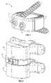
- FIG. 1is an isometric view of one example of an interbody fusion device of the present invention.
- FIG. 2is an isometric diagram of the interbody fusion device shown in FIG. 1 installed between the end plates of two adjacent vertebrae.
- FIG. 3is an exploded view of an interbody fusion device, showing a load bearing device and a retention device.
- FIG. 4is an isometric diagram of the interbody fusion device shown in FIG. 3 with the retention device inserted into the load bearing device.
- FIG. 5is a top view of the assembled interbody fusion device shown in FIG. 4 .
- FIG. 6is a sectional diagram taken along line 6 - 6 of FIG. 5 .
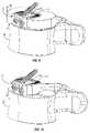
- FIG. 7is an isometric diagram of an interbody fusion device utilizing an anti-backout mechanism.
- FIG. 8is a side view of the interbody fusion device and vertebrae shown in FIG. 2 .
- FIG. 9is an isometric view similar to FIG. 2 , but with the upper vertebra removed.
- FIG. 10is an isometric view similar to FIG. 9 , but with the disc annulus and nucleus pulpous removed.
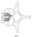
- FIG. 11is a top view of the interbody fusion device and vertebral body shown in FIG. 10 .
- the present inventionrelates to spinal fusion implants and related spinal fusion procedures for use in cervical and lumbar applications.
- spinal fusionis interbody fusion.
- an interbody fusion procedureplaces a bone graft between the vertebra in the area normally occupied by an intervertebral disc.
- the intervertebral discis removed entirely.
- a devicemay be placed between the vertebra to maintain spine alignment and disc height. Fusion then occurs between the endplates of the vertebrae.
- fusionis augmented by a process called fixation, meaning the placement of screws, rods or plates to stabilize the vertebra to facilitate bone fusion.
- fixationmeaning the placement of screws, rods or plates to stabilize the vertebra to facilitate bone fusion.
- the present inventionprovides an interbody fusion device that overcomes problems found in the prior art.
- the present inventionprovides a two piece interbody fusion device that may be used with anterior lumbar interbody fusion (ALIF).
- a first piece of the interbody fusion deviceis a U-shaped load bearing device that is designed to bear the axial loading from the end plates of adjacent vertebrae.
- a second piece of the interbody fusion deviceis a retention device whose function is to prevent migration of the load bearing device.
- One or more fastenerssuch as bone screws secure the retention device to the vertebrae above and below the load bearing device. The fasteners cause the end plates of the vertebrae to compress the end plates to the load bearing device to facilitate proper fusion.
- the fastenersmay include an anti-backout mechanism.
- FIG. 1is an isometric view of one example of an interbody fusion device of the present invention.
- FIG. 1shows an interbody fusion device 10 .
- the interbody fusion device 10includes a load bearing device 12 , a retention device 14 , and two bone screws 16 , each of which are described in more detail below.
- FIG. 2is an isometric diagram of the interbody fusion device 10 shown in FIG. 1 installed between the end plates of two adjacent vertebrae 20 and 22 to facilitate the fusion of the vertebrae 20 and 22 .
- the interbody fusion device 10provides load bearing support as well as the proper spacing between the vertebrae 20 and 22 while fusion of the vertebrae takes place. As described in more detail below, the interbody fusion device 10 is positioned between the end plates of the vertebrae 20 and 22 within the vertebral body in the area usually occupied by the intervertebral disc.
- FIGS. 3-6are views illustrating various details of one example of an interbody fusion device of the present invention.
- FIG. 3is an exploded view of the interbody fusion device 10 , showing the load bearing device 12 and the retention device 14 separately.
- the load bearing device 12is a generally U-shaped device having an open end 30 that is configured to receive the retention device 14 (described below).
- a groove 32is formed around the interior surface 34 of the load bearing device 12 .
- a corresponding tongue 36is formed around the outside surface of the retention device 14 such that, when the retention device 14 is inserted within the open end 30 of the load bearing device 12 , the tongue 36 and groove 32 tend to hold the retention device 14 in a desired position, relative to the load bearing device 12 .
- the load bearing device 12also includes a plurality of ridges 38 formed on the top and bottom ends of the device 12 .
- the ridges 38are angled and come to a point in such a way that the ridges 38 help to hold the load bearing device 12 to the end plates of the vertebrae to reduce the chance of anterior migration of the implant.
- one or more openings 40can be formed in the load bearing device 12 to facilitate instrumentation devices. In the example shown in FIG. 3 , two openings 40 are formed on opposite sides of the load bearing device 12 (the second opening 40 is hidden in FIG. 3 ).
- An implant holdercan be used to insert the load bearing device 12 into a vertebral body using the openings 40 .
- the retention device 14has a front portion 42 and a rear portion 44 that, together, form a hollow body 46 .
- the hollow body 46provides a relatively large graft volume, compared to a typical ALIF allograft.
- the hollow body 46 of the retention device 14can be filled with a prepared material that will help to facilitate fusion of the vertebrae (see FIGS. 9-10 ). Examples of a material include allograft bone, bone marrow, bone morphonogenic protein (BMP), Autologous Stem Cells, etc., to facilitate fusion through opening 46 .
- BMPbone morphonogenic protein
- the retention device 14is shaped to such that it will fit within the open end 30 of the load bearing device 12 .
- two holes 48are formed in the front portion 42 , and are adapted to received fasteners, such as bone screws, pegs, etc.
- One of the holes 48is angled down, and the other hole 48 is angled up, such that a first fastener can be secured to the vertebra above the interbody fusion device 10 , and a second fastener can be secured to the vertebra below the interbody fusion device 10 (described in more detail below).
- FIG. 4is an isometric diagram of the interbody fusion device 10 shown in FIG. 3 with the retention device 14 inserted into the load bearing device 12 .
- the retention device 14fits within the load bearing device 12 .
- the resulting assemblyprovides a load bearing structure that is safely secured in place without any fasteners having to be placed directly into the load bearing device 12 .
- FIG. 4also illustrates that the height of the retention device 14 is less than the height of the load bearing device 12 . As a result, all of the load on the vertebrae will be placed on the load bearing device 12 , and not on the retention device 14 . At the same time the load bearing device 12 is securely is the position desired by the surgeon.
- the fastening mechanismse.g., cervical plates with screws, spacers held in place by off-set screws, etc.
- the load bearing structurewill remain stationary, even as bone screws are tightened to secure the retention device in place.
- FIG. 5is a top view of the assembled interbody fusion device 10 shown in FIG. 4 .
- the interbody fusion device 10has a generally round profile, that substantially fits within a vertebral body (shown in more detail below).
- FIG. 5also illustrates how the load bearing device 12 is securely held in place by the retention device 14 , such that anterior and lateral migration is prevented. Also note that that trailing edges 18 of the load bearing device 12 are nested and contained in pockets 28 formed in the retention device 14 . This further secures the load bearing device 12 in place.
- FIG. 6is a sectional diagram taken along line 6 - 6 of FIG. 5 .
- FIG. 6shows the retention device 14 , including the front portion 42 and the rear portion 44 , which forms the hollow body 46 .
- the tongue 36 of the retention device 14fits within the groove 32 of the load bearing device 12 .
- FIG. 6also more clearly illustrates that the height of the load bearing device 12 is greater than the height of the retention device 14 .
- the load bearing device 12will be the structure (primarily, the ridges 38 ) that engages the end plates of the vertebrae, thus supporting the axial loading of the vertebrae.
- FIG. 7is an isometric diagram of the interbody fusion device 10 utilizing an anti-backout mechanism.
- the anti-backout mechanismis comprised of a set screw 50 , which can be screwed into the front portion of the retention device 14 .
- the set screw in this exampleincludes a driver socket for receiving a driver, which may be used by a surgeon to tighten the set screw 50 .
- any desired type of anti-backout devicemay also be used.
- a interbody fusion device of the present inventionis intended to be installed between the end plates of two adjacent vertebrae to facilitate the fusion of the vertebrae.
- FIGS. 8-11further illustrate the installation of an interbody fusion device of the present invention between adjacent vertebrae.
- FIG. 8is a side view of the interbody fusion device 10 and vertebrae shown in FIG. 2 .
- the interbody fusion device 10has a zero-profile anteriorly.
- the interbody fusion device 10has a shape (e.g., see FIG. 5 ) in the axial plane that substantially fits within the perimeter defined by the vertebrae.
- a cervical plate, or similar structureis affixed to the side of the vertebrae, creating an extending profile that can cause discomfort, or damage to nearby tissue.
- the interbody fusion device 10(not including the bone screws 16 ) also does not extend beyond (above or below) the end plates of the vertebrae.
- the intervertebral discPrior to the insertion of the interbody fusion device 10 , the intervertebral disc is removed, so the interbody fusion device 10 can be place between the vertebrae 20 and 22 .
- a windowis cut in the disc annulus 24 .
- portions of the nucleus pulposus 26FIGS. 9 , 10 ) are removed so that the interbody fusion device 10 can fit between the vertebrae 20 and 22 as shown in the figures.
- FIG. 9is an isometric view similar to FIG. 2 , but with the vertebra 20 removed to illustrate how the interbody fusion device 10 is positioned relative to the vertebrae and disc annulus 24 .
- FIG. 9shows the disc annulus 24 with a portion removed to allow the interbody fusion device 10 to be inserted.
- FIG. 9also shows the remaining nucleus pulpous 26 surrounding the interbody fusion device 10 .
- FIG. 10is an isometric view similar to FIG. 9 , but with the disc annulus 24 and nucleus pulpous 26 removed to further illustrate how the interbody fusion device 10 is positioned relative to the vertebrae and disc annulus 24 .
- FIGS. 9 and 10also include shading, which represents fusion material 60 , described above.
- FIG. 11is a top view of the interbody fusion device 10 and vertebral body shown in FIG. 10 . Note that, for clarity, the material 60 is not shown in FIG. 11 .
- a interbody fusion device of the present inventionmay be used in an ALIF spinal fusion procedure.
- a windowis cut in the anterior side of the disc annulus 24 ( FIG. 9 ) to allow an interbody fusion device to be inserted.
- the nucleus pulposus 26is cleaned out to provide room for the interbody fusion device.
- a load bearing device 12 of the desired sizee.g., having a height to get the desired spacing between the vertebrae
- the retention device 14can be prepared with a desire material 60 placed in the hollow body 46 .
- the retention device 14is inserted into the load bearing device 12 , with the tongue 36 and groove 32 guiding the retention device 14 .
- the retention device 14can slide into the load bearing device 12 without interfering with the relative placement of the load bearing device 12 and the end plates of the adjacent vertebrae.
- the retention device 14is stress shielded and is not axial loaded by the vertebrae.
- an anti-backout mechanism(such as the set screw 50 shown in FIG. 7 ) can be used to prevent the bone screws 16 from loosening.
- the interbody fusion device of the present inventioncan be made from any desired materials.
- the load bearing deviceis made from PEEK® (or a similar material), bone, metal, or any other structural substitute.
- the retention deviceis made from PEEK® (or a similar material), bone, metal, or any other structural substitute. If the components of the interbody fusion device are radio-lucent (such as with PEEK®), then doctors will be able monitor the fusion process better with X-rays.
- An interbody fusion device of the present inventionmay be configured to any desired size or shape.
- load bearing devicescan be provided in multiple thicknesses, allowing a surgeon to select a desired size (e.g., 10.5 mm, 12.5 mm, 14.5 mm, 16.5 mm, 1.5 mm, etc.).
- the load bearing devicehas about 6° of lordosis (e.g., see FIG. 6 ). Of course any desired angle could be used.
Landscapes
- Health & Medical Sciences (AREA)
- Engineering & Computer Science (AREA)
- Biomedical Technology (AREA)
- Orthopedic Medicine & Surgery (AREA)
- Neurology (AREA)
- Life Sciences & Earth Sciences (AREA)
- Animal Behavior & Ethology (AREA)
- Veterinary Medicine (AREA)
- Public Health (AREA)
- Heart & Thoracic Surgery (AREA)
- General Health & Medical Sciences (AREA)
- Cardiology (AREA)
- Vascular Medicine (AREA)
- Transplantation (AREA)
- Oral & Maxillofacial Surgery (AREA)
- Surgery (AREA)
- Nuclear Medicine, Radiotherapy & Molecular Imaging (AREA)
- Medical Informatics (AREA)
- Molecular Biology (AREA)
- Prostheses (AREA)
- Surgical Instruments (AREA)
Abstract
Description
Claims (11)
Priority Applications (7)
| Application Number | Priority Date | Filing Date | Title |
|---|---|---|---|
| US11/759,219US8273127B2 (en) | 2007-06-06 | 2007-06-06 | Interbody fusion device and associated methods |
| US12/018,703US8795373B2 (en) | 2007-06-06 | 2008-01-23 | Interbody fusion device, integral retention device, and associated methods |
| EP08770256AEP2166993A1 (en) | 2007-06-06 | 2008-06-06 | Interbody fusion device, integral retention device, and associated methods |
| PCT/US2008/066012WO2008154326A1 (en) | 2007-06-06 | 2008-06-06 | Interbody fusion device, integral retention device, and associated methods |
| US13/200,911US8597353B2 (en) | 2007-06-06 | 2011-10-04 | Interbody fusion device and associated methods |
| US13/506,565US9114023B2 (en) | 2007-06-06 | 2012-04-27 | Interbody fusion device with snap on anterior plate and associated methods |
| US13/506,566US10034764B2 (en) | 2007-06-06 | 2012-04-27 | Interbody fusion device with lipped anterior plate and associated methods |
Applications Claiming Priority (3)
| Application Number | Priority Date | Filing Date | Title |
|---|---|---|---|
| US11/759,219US8273127B2 (en) | 2007-06-06 | 2007-06-06 | Interbody fusion device and associated methods |
| US98141407P | 2007-10-19 | 2007-10-19 | |
| US12/018,703US8795373B2 (en) | 2007-06-06 | 2008-01-23 | Interbody fusion device, integral retention device, and associated methods |
Related Parent Applications (1)
| Application Number | Title | Priority Date | Filing Date |
|---|---|---|---|
| US12/018,703Continuation-In-PartUS8795373B2 (en) | 2007-06-06 | 2008-01-23 | Interbody fusion device, integral retention device, and associated methods |
Related Child Applications (2)
| Application Number | Title | Priority Date | Filing Date |
|---|---|---|---|
| US12/018,703Continuation-In-PartUS8795373B2 (en) | 2007-06-06 | 2008-01-23 | Interbody fusion device, integral retention device, and associated methods |
| US13/200,911Continuation-In-PartUS8597353B2 (en) | 2007-06-06 | 2011-10-04 | Interbody fusion device and associated methods |
Publications (2)
| Publication Number | Publication Date |
|---|---|
| US20080306596A1 US20080306596A1 (en) | 2008-12-11 |
| US8273127B2true US8273127B2 (en) | 2012-09-25 |
Family
ID=40096601
Family Applications (2)
| Application Number | Title | Priority Date | Filing Date |
|---|---|---|---|
| US11/759,219Active2031-06-21US8273127B2 (en) | 2007-06-06 | 2007-06-06 | Interbody fusion device and associated methods |
| US12/018,703Active2029-03-02US8795373B2 (en) | 2007-06-06 | 2008-01-23 | Interbody fusion device, integral retention device, and associated methods |
Family Applications After (1)
| Application Number | Title | Priority Date | Filing Date |
|---|---|---|---|
| US12/018,703Active2029-03-02US8795373B2 (en) | 2007-06-06 | 2008-01-23 | Interbody fusion device, integral retention device, and associated methods |
Country Status (3)
| Country | Link |
|---|---|
| US (2) | US8273127B2 (en) |
| EP (1) | EP2166993A1 (en) |
| WO (1) | WO2008154326A1 (en) |
Cited By (42)
| Publication number | Priority date | Publication date | Assignee | Title |
|---|---|---|---|---|
| US20100057206A1 (en)* | 2008-09-02 | 2010-03-04 | Duffield William E | Intervertebral fusion implant |
| US20120323330A1 (en)* | 2007-11-16 | 2012-12-20 | Synthes Usa, Llc | Low profile intervertebral implant |
| US20120330419A1 (en)* | 2005-04-12 | 2012-12-27 | Moskowitz Nathan C | Bi-directional fixating/locking transvertebral body screw/intervertebral cage stand-alone constructs |
| US8753396B1 (en) | 2010-09-13 | 2014-06-17 | Theken Spine, Llc | Intervertebral implant having back-out prevention feature |
| USD731061S1 (en) | 2012-11-28 | 2015-06-02 | Nuvasive, Inc. | Intervertebral implant |
| US9149365B2 (en) | 2013-03-05 | 2015-10-06 | Globus Medical, Inc. | Low profile plate |
| US9155631B2 (en) | 2010-04-08 | 2015-10-13 | Globus Medical Inc. | Intervertbral implant |
| US20150328010A1 (en)* | 2014-05-15 | 2015-11-19 | Globus Medical, Inc. | Standalone interbody implants |
| US20150328009A1 (en)* | 2014-05-15 | 2015-11-19 | Globus Medical, Inc. | Standalone Interbody Implants |
| US9192419B2 (en) | 2008-11-07 | 2015-11-24 | DePuy Synthes Products, Inc. | Zero-profile interbody spacer and coupled plate assembly |
| US9220604B2 (en) | 2010-12-21 | 2015-12-29 | DePuy Synthes Products, Inc. | Intervertebral implants, systems, and methods of use |
| US9237957B2 (en) | 2011-09-16 | 2016-01-19 | Globus Medical, Inc. | Low profile plate |
| US9241809B2 (en) | 2010-12-21 | 2016-01-26 | DePuy Synthes Products, Inc. | Intervertebral implants, systems, and methods of use |
| US9301854B2 (en) | 2005-04-12 | 2016-04-05 | Ahmnon D. Moskowitz | Bi-directional fixating transvertebral body screws and posterior cervical and lumbar interarticulating joint calibrated stapling devices for spinal fusion |
| US9398960B2 (en) | 2011-09-16 | 2016-07-26 | Globus Medical, Inc. | Multi-piece intervertebral implants |
| US9463097B2 (en) | 2003-02-06 | 2016-10-11 | DePuy Synthes Products, Inc. | Intervertebral implant |
| US9468536B1 (en) | 2011-11-02 | 2016-10-18 | Nuvasive, Inc. | Spinal fusion implants and related methods |
| US9532821B2 (en) | 2005-04-12 | 2017-01-03 | Nathan C. Moskowitz | Bi-directional fixating/locking transvertebral body screw/intervertebral cage stand-alone constructs with vertical hemi-bracket screw locking mechanism |
| US9539109B2 (en) | 2011-09-16 | 2017-01-10 | Globus Medical, Inc. | Low profile plate |
| US9572681B2 (en) | 2002-02-19 | 2017-02-21 | DePuy Synthes Products, Inc. | Intervertebral implant |
| US9681959B2 (en) | 2011-09-16 | 2017-06-20 | Globus Medical, Inc. | Low profile plate |
| US9814601B2 (en) | 2005-04-12 | 2017-11-14 | Nathan C. Moskowitz | Bi-directional fixating/locking transvertebral body screw/intervertebral cage stand-alone constructs |
| US9848994B2 (en)* | 2011-09-16 | 2017-12-26 | Globus Medical, Inc. | Low profile plate |
| US9848993B2 (en) | 2005-04-12 | 2017-12-26 | Nathan C. Moskowitz | Zero-profile expandable intervertebral spacer devices for distraction and spinal fusion and a universal tool for their placement and expansion |
| US9867718B2 (en) | 2014-10-22 | 2018-01-16 | DePuy Synthes Products, Inc. | Intervertebral implants, systems, and methods of use |
| US9937055B1 (en) | 2016-11-28 | 2018-04-10 | Spine Wave, Inc. | Scoring implant trial and implant inserter for spinal fusion system |
| US10076367B2 (en) | 2005-04-12 | 2018-09-18 | Moskowitz Family Llc | Bi-directional fixating transvertebral body screws, zero-profile horizontal intervertebral miniplates, total intervertebral body fusion devices, and posterior motion-calibrating interarticulating joint stapling device for spinal fusion |
| US10219916B2 (en) | 2014-01-17 | 2019-03-05 | Spine Wave, Inc. | Method for fusing spinal vertebrae |
| US10245155B2 (en) | 2011-09-16 | 2019-04-02 | Globus Medical, Inc. | Low profile plate |
| US10271960B2 (en) | 2017-04-05 | 2019-04-30 | Globus Medical, Inc. | Decoupled spacer and plate and method of installing the same |
| US10363145B2 (en) | 2015-02-23 | 2019-07-30 | Amendia, Inc. | Lateral plate and spinal implant system and method |
| US10376385B2 (en) | 2017-04-05 | 2019-08-13 | Globus Medical, Inc. | Decoupled spacer and plate and method of installing the same |
| US10500063B2 (en) | 2016-10-14 | 2019-12-10 | Spine Wave, Inc. | Modular interbody fusion device |
| US10512548B2 (en) | 2006-02-27 | 2019-12-24 | DePuy Synthes Products, Inc. | Intervertebral implant with fixation geometry |
| US10610375B2 (en) | 2015-08-19 | 2020-04-07 | Raymond J. Quinlan | Spinal fusion device and method of using same |
| US10736752B1 (en) | 2017-10-24 | 2020-08-11 | Omnia Medical, LLC | Multi-material multi-component spinal implant |
| US10842642B2 (en) | 2009-04-16 | 2020-11-24 | Nuvasive, Inc. | Methods and apparatus of performing spine surgery |
| US10888434B2 (en) | 2017-10-05 | 2021-01-12 | Spine Wave, Inc. | Modular scoring trial for anterior cervical cage |
| US11160666B2 (en)* | 2014-05-15 | 2021-11-02 | Globus Medical, Inc. | Laterally insertable intervertebral spinal implant |
| US11717417B2 (en) | 2011-09-16 | 2023-08-08 | Globus Medical Inc. | Low profile plate |
| US11766339B1 (en) | 2017-10-24 | 2023-09-26 | Omnia Medical, LLC | Multi-material multi-component spinal implant |
| US11903849B2 (en) | 2005-04-12 | 2024-02-20 | Moskowitz Family Llc | Intervertebral implant and tool assembly |
Families Citing this family (127)
| Publication number | Priority date | Publication date | Assignee | Title |
|---|---|---|---|---|
| US6206922B1 (en)* | 1995-03-27 | 2001-03-27 | Sdgi Holdings, Inc. | Methods and instruments for interbody fusion |
| FR2897259B1 (en) | 2006-02-15 | 2008-05-09 | Ldr Medical Soc Par Actions Si | INTERSOMATIC TRANSFORAMINAL CAGE WITH INTERBREBAL FUSION GRAFT AND CAGE IMPLANTATION INSTRUMENT |
| FR2824261B1 (en) | 2001-05-04 | 2004-05-28 | Ldr Medical | INTERVERTEBRAL DISC PROSTHESIS AND IMPLEMENTATION METHOD AND TOOLS |
| FR2827156B1 (en) | 2001-07-13 | 2003-11-14 | Ldr Medical | VERTEBRAL CAGE DEVICE WITH MODULAR FASTENING |
| FR2846550B1 (en) | 2002-11-05 | 2006-01-13 | Ldr Medical | INTERVERTEBRAL DISC PROSTHESIS |
| US7819903B2 (en) | 2003-03-31 | 2010-10-26 | Depuy Spine, Inc. | Spinal fixation plate |
| EP2113227B1 (en) | 2004-02-04 | 2015-07-29 | LDR Medical | Intervertebral disc prosthesis |
| FR2865629B1 (en) | 2004-02-04 | 2007-01-26 | Ldr Medical | INTERVERTEBRAL DISC PROSTHESIS |
| FR2869528B1 (en) | 2004-04-28 | 2007-02-02 | Ldr Medical | INTERVERTEBRAL DISC PROSTHESIS |
| WO2006058221A2 (en) | 2004-11-24 | 2006-06-01 | Abdou Samy M | Devices and methods for inter-vertebral orthopedic device placement |
| FR2879436B1 (en) | 2004-12-22 | 2007-03-09 | Ldr Medical | INTERVERTEBRAL DISC PROSTHESIS |
| FR2891135B1 (en) | 2005-09-23 | 2008-09-12 | Ldr Medical Sarl | INTERVERTEBRAL DISC PROSTHESIS |
| FR2893838B1 (en) | 2005-11-30 | 2008-08-08 | Ldr Medical Soc Par Actions Si | PROSTHESIS OF INTERVERTEBRAL DISC AND INSTRUMENTATION OF INSERTION OF THE PROSTHESIS BETWEEN VERTEBRATES |
| US7887595B1 (en) | 2005-12-05 | 2011-02-15 | Nuvasive, Inc. | Methods and apparatus for spinal fusion |
| US8114162B1 (en) | 2006-08-09 | 2012-02-14 | Nuvasive, Inc. | Spinal fusion implant and related methods |
| USD708747S1 (en) | 2006-09-25 | 2014-07-08 | Nuvasive, Inc. | Spinal fusion implant |
| US9039768B2 (en) | 2006-12-22 | 2015-05-26 | Medos International Sarl | Composite vertebral spacers and instrument |
| US8465546B2 (en) | 2007-02-16 | 2013-06-18 | Ldr Medical | Intervertebral disc prosthesis insertion assemblies |
| US10034764B2 (en)* | 2007-06-06 | 2018-07-31 | Spinesmith Partners, L.P. | Interbody fusion device with lipped anterior plate and associated methods |
| US8882813B2 (en)* | 2007-10-19 | 2014-11-11 | Spinesmith Partners, L.P. | Locking mechanisms and associated methods |
| US8273127B2 (en)* | 2007-06-06 | 2012-09-25 | Spinesmith Partners, L.P. | Interbody fusion device and associated methods |
| FR2916956B1 (en) | 2007-06-08 | 2012-12-14 | Ldr Medical | INTERSOMATIC CAGE, INTERVERTEBRAL PROSTHESIS, ANCHORING DEVICE AND IMPLANTATION INSTRUMENTATION |
| US20090177239A1 (en)* | 2007-08-06 | 2009-07-09 | Michael Castro | Cervical plate instrument kit |
| US20090248092A1 (en) | 2008-03-26 | 2009-10-01 | Jonathan Bellas | Posterior Intervertebral Disc Inserter and Expansion Techniques |
| US8470040B2 (en)* | 2008-04-02 | 2013-06-25 | Pioneer Surgical Technology, Inc. | Intervertebral implant devices for supporting vertebrae and devices and methods for insertion thereof |
| US8936641B2 (en) | 2008-04-05 | 2015-01-20 | DePuy Synthes Products, LLC | Expandable intervertebral implant |
| US8652182B1 (en)* | 2008-10-01 | 2014-02-18 | Spinal U.S.A. | Bone plate with retainer and stop for screw lock |
| WO2010079993A2 (en)* | 2009-01-09 | 2010-07-15 | (주)위노바 | Intervertebral cage |
| KR101040515B1 (en)* | 2009-01-09 | 2011-06-16 | 주식회사 위노바 | Intervertebral Fixed Prosthesis |
| WO2010096773A1 (en)* | 2009-02-20 | 2010-08-26 | Spartan Cage Holding, Llc | Interbody fusion system with intervertebral implant retention assembly |
| US9526620B2 (en) | 2009-03-30 | 2016-12-27 | DePuy Synthes Products, Inc. | Zero profile spinal fusion cage |
| US8641766B2 (en) | 2009-04-15 | 2014-02-04 | DePuy Synthes Products, LLC | Arcuate fixation member |
| US9408715B2 (en) | 2009-04-15 | 2016-08-09 | DePuy Synthes Products, Inc. | Arcuate fixation member |
| US9095444B2 (en) | 2009-07-24 | 2015-08-04 | Warsaw Orthopedic, Inc. | Implant with an interference fit fastener |
| CN105326585B (en) | 2009-09-17 | 2018-12-11 | Ldr控股公司 | Intervertebral implant with extensible bone anchoring element |
| KR101136427B1 (en)* | 2009-09-25 | 2012-04-20 | (주)엘앤케이바이오메드 | Cervical intervertebral fusion device |
| US8840668B1 (en) | 2009-11-11 | 2014-09-23 | Nuvasive, Inc. | Spinal implants, instruments and related methods |
| US8740983B1 (en) | 2009-11-11 | 2014-06-03 | Nuvasive, Inc. | Spinal fusion implants and related methods |
| US8764806B2 (en) | 2009-12-07 | 2014-07-01 | Samy Abdou | Devices and methods for minimally invasive spinal stabilization and instrumentation |
| US9393129B2 (en) | 2009-12-10 | 2016-07-19 | DePuy Synthes Products, Inc. | Bellows-like expandable interbody fusion cage |
| WO2011080535A1 (en) | 2009-12-31 | 2011-07-07 | Lrd Medical | Anchoring device, intervertebral implant and implantation instrument |
| US9408718B2 (en) | 2009-12-31 | 2016-08-09 | Rhausler, Inc. | Inter-vertebral implant with angled plate |
| US8945226B2 (en)* | 2009-12-31 | 2015-02-03 | Rhausler | Vertebral spacer |
| BRPI1002012A2 (en)* | 2010-02-11 | 2011-06-14 | M D T Ind E Com De Implantes Ortopedicos Ltda | anterior intervertebral fusion system of the lumbar spine |
| EP2547292B1 (en) | 2010-03-16 | 2019-04-24 | Pinnacle Spine Group, LLC | Ntervertebral implants and graft delivery systems |
| US8377139B2 (en) | 2010-06-17 | 2013-02-19 | Aesculap Implant Systems, Llc | Standalone interbody fusion device with locking and release mechanism |
| US9241810B1 (en)* | 2010-07-12 | 2016-01-26 | Spinesmith Partners, L.P. | Fusion device and associated methods |
| US20120078373A1 (en) | 2010-09-23 | 2012-03-29 | Thomas Gamache | Stand alone intervertebral fusion device |
| US11529241B2 (en) | 2010-09-23 | 2022-12-20 | DePuy Synthes Products, Inc. | Fusion cage with in-line single piece fixation |
| US20120078372A1 (en) | 2010-09-23 | 2012-03-29 | Thomas Gamache | Novel implant inserter having a laterally-extending dovetail engagement feature |
| WO2012094647A2 (en)* | 2011-01-06 | 2012-07-12 | Bergey Darren L | Interbody vertebral prosthetic device with blade anchor |
| US8940030B1 (en) | 2011-01-28 | 2015-01-27 | Nuvasive, Inc. | Spinal fixation system and related methods |
| US20120209385A1 (en)* | 2011-02-15 | 2012-08-16 | Joshua Michael Aferzon | Anterior intervertebral fusion with fixation system, device and method |
| US9579214B1 (en) | 2011-03-01 | 2017-02-28 | John W. McClellan | Peripheral vertebral body spacer implant and insertion tool |
| US20120245693A1 (en)* | 2011-03-25 | 2012-09-27 | Josef Gorek | Spinal fixation device |
| US9017412B2 (en) | 2011-04-29 | 2015-04-28 | Life Spine, Inc. | Spinal interbody implant with bone screw retention |
| US10166115B2 (en)* | 2011-07-12 | 2019-01-01 | Spinesmith Partners, L.P. | Interbody fusion device |
| US9724132B2 (en) | 2011-08-31 | 2017-08-08 | DePuy Synthes Products, Inc. | Devices and methods for cervical lateral fixation |
| US9277946B2 (en) | 2011-09-06 | 2016-03-08 | Amendia, Inc. | Spinal fusion system |
| US9248028B2 (en) | 2011-09-16 | 2016-02-02 | DePuy Synthes Products, Inc. | Removable, bone-securing cover plate for intervertebral fusion cage |
| US8845728B1 (en) | 2011-09-23 | 2014-09-30 | Samy Abdou | Spinal fixation devices and methods of use |
| US9380932B1 (en) | 2011-11-02 | 2016-07-05 | Pinnacle Spine Group, Llc | Retractor devices for minimally invasive access to the spine |
| US9913732B2 (en)* | 2011-11-02 | 2018-03-13 | Spinesmith Partners, L.P. | Interbody fusion device with separable retention component for lateral approach and associated methods |
| US8795167B2 (en) | 2011-11-15 | 2014-08-05 | Baxano Surgical, Inc. | Spinal therapy lateral approach access instruments |
| US9370435B2 (en)* | 2011-11-17 | 2016-06-21 | Zimmer Biomet Spine, Inc. | Modular anchor bone fusion cage |
| US20130226240A1 (en) | 2012-02-22 | 2013-08-29 | Samy Abdou | Spinous process fixation devices and methods of use |
| FR2987256B1 (en) | 2012-02-24 | 2014-08-08 | Ldr Medical | ANCHORING DEVICE FOR INTERVERTEBRAL IMPLANT, INTERVERTEBRAL IMPLANT AND IMPLANTATION INSTRUMENTATION |
| US9271836B2 (en) | 2012-03-06 | 2016-03-01 | DePuy Synthes Products, Inc. | Nubbed plate |
| US9693876B1 (en)* | 2012-03-30 | 2017-07-04 | Ali H. MESIWALA | Spinal fusion implant and related methods |
| US8814912B2 (en) | 2012-07-27 | 2014-08-26 | Zimmer Spine, Inc. | Bone stabilization member with bone screw retention mechanism |
| US9326861B2 (en) | 2012-08-03 | 2016-05-03 | Globus Medical, Inc. | Stabilizing joints |
| US9198767B2 (en) | 2012-08-28 | 2015-12-01 | Samy Abdou | Devices and methods for spinal stabilization and instrumentation |
| US9186257B2 (en)* | 2012-10-11 | 2015-11-17 | Rhausler, Inc. | Bone plate and fusion cage interface |
| US9320617B2 (en) | 2012-10-22 | 2016-04-26 | Cogent Spine, LLC | Devices and methods for spinal stabilization and instrumentation |
| US10182921B2 (en) | 2012-11-09 | 2019-01-22 | DePuy Synthes Products, Inc. | Interbody device with opening to allow packing graft and other biologics |
| US9572680B2 (en) | 2013-01-25 | 2017-02-21 | K2M, Inc. | Spinal implants, spinal implant kits, and surgical methods |
| US9522070B2 (en) | 2013-03-07 | 2016-12-20 | Interventional Spine, Inc. | Intervertebral implant |
| WO2014159739A1 (en) | 2013-03-14 | 2014-10-02 | Pinnacle Spine Group, Llc | Interbody implants and graft delivery systems |
| US10322006B2 (en)* | 2013-03-15 | 2019-06-18 | Globus Medical, Inc. | Interbody standalone intervertebral implant |
| FR3005569B1 (en) | 2013-05-16 | 2021-09-03 | Ldr Medical | VERTEBRAL IMPLANT, VERTEBRAL IMPLANT FIXATION DEVICE AND IMPLANTATION INSTRUMENTATION |
| US9918848B2 (en)* | 2013-10-07 | 2018-03-20 | Warsaw Orthopedic, Inc. | Spinal implant system and method |
| USD745159S1 (en)* | 2013-10-10 | 2015-12-08 | Nuvasive, Inc. | Intervertebral implant |
| FR3016793B1 (en) | 2014-01-30 | 2021-05-07 | Ldr Medical | ANCHORING DEVICE FOR SPINAL IMPLANT, SPINAL IMPLANT AND IMPLANTATION INSTRUMENTATION |
| US9889014B2 (en) | 2014-02-06 | 2018-02-13 | Life Spine, Inc. | Implant for bone fixation |
| US9877759B2 (en) | 2014-02-06 | 2018-01-30 | Life Spine, Inc. | Foot implant for bone fixation |
| US10426630B2 (en) | 2014-02-12 | 2019-10-01 | K2M, Inc. | Spinal implant |
| EP3110352B1 (en)* | 2014-02-25 | 2023-03-29 | Refai Technologies, LLC | Spinal cage device, system, and methods of assembly and use |
| FR3020756B1 (en) | 2014-05-06 | 2022-03-11 | Ldr Medical | VERTEBRAL IMPLANT, VERTEBRAL IMPLANT FIXATION DEVICE AND IMPLANT INSTRUMENTATION |
| CN104068949B (en)* | 2014-07-18 | 2016-07-06 | 山东威高骨科材料有限公司 | Anterior cervical vertebrae zero incisura inter vertebral fusing device |
| EP3203938B1 (en)* | 2014-10-08 | 2022-12-07 | Globus Medical, Inc. | Standalone interbody implants |
| USD858769S1 (en)* | 2014-11-20 | 2019-09-03 | Nuvasive, Inc. | Intervertebral implant |
| US10039648B2 (en) | 2015-05-06 | 2018-08-07 | Choice Spine, Lp | Intervertebral implant device |
| US10034768B2 (en)* | 2015-09-02 | 2018-07-31 | Globus Medical, Inc. | Implantable systems, devices and related methods |
| US10857003B1 (en) | 2015-10-14 | 2020-12-08 | Samy Abdou | Devices and methods for vertebral stabilization |
| KR101609582B1 (en)* | 2015-10-19 | 2016-04-06 | (주)엘앤케이바이오메드 | Surgical screw and fusion device using thereof |
| KR101609581B1 (en)* | 2015-10-19 | 2016-04-06 | (주)엘앤케이바이오메드 | Surgical screw and fusion device using thereof |
| USD790704S1 (en)* | 2016-04-11 | 2017-06-27 | Dongguk University Gyeongju Campus Industry-Academy Cooperation Foundation | Cage for cervical spine |
| US20200000595A1 (en) | 2016-06-07 | 2020-01-02 | HD LifeSciences LLC | High X-Ray Lucency Lattice Structures |
| EP3474784A2 (en) | 2016-06-28 | 2019-05-01 | Eit Emerging Implant Technologies GmbH | Expandable and angularly adjustable intervertebral cages with articulating joint |
| US10258483B2 (en)* | 2016-08-19 | 2019-04-16 | Degen Medical, Inc. | Laminate implantable medical devices |
| US10744000B1 (en) | 2016-10-25 | 2020-08-18 | Samy Abdou | Devices and methods for vertebral bone realignment |
| US10973648B1 (en) | 2016-10-25 | 2021-04-13 | Samy Abdou | Devices and methods for vertebral bone realignment |
| CA3061043A1 (en) | 2017-02-14 | 2018-08-23 | HD LifeSciences LLC | High x-ray lucency lattice structures and variably x-ray lucent markers |
| EP3606473A4 (en) | 2017-04-01 | 2020-12-30 | HD Lifesciences LLC | FLUID INTERFACE SYSTEM FOR IMPLANTS |
| CA3058365A1 (en) | 2017-04-01 | 2018-10-04 | HD LifeSciences LLC | Three-dimensional lattice structures for implants |
| US10940016B2 (en) | 2017-07-05 | 2021-03-09 | Medos International Sarl | Expandable intervertebral fusion cage |
| USD835277S1 (en)* | 2017-08-01 | 2018-12-04 | Ikon Spine LLC | Anterior lumbar interbody fusion device |
| USD835788S1 (en)* | 2017-08-08 | 2018-12-11 | HD LifeSciences LLC | Interbody fusion implant |
| WO2019051260A1 (en) | 2017-09-08 | 2019-03-14 | Pioneer Surgical Technology, Inc. | Intervertebral implants, instruments, and methods |
| US11801144B2 (en) | 2017-09-14 | 2023-10-31 | Degen Medical, Inc. | Methods of making medical devices |
| USD907771S1 (en) | 2017-10-09 | 2021-01-12 | Pioneer Surgical Technology, Inc. | Intervertebral implant |
| CN108969163B (en)* | 2017-12-28 | 2021-06-25 | 浙江德康医疗器械有限公司 | A zero-notch fusion device |
| EP3826582A4 (en) | 2018-07-26 | 2022-05-25 | Nanohive Medical LLC | DYNAMIC IMPLANT FIXATION PLATE |
| US11179248B2 (en) | 2018-10-02 | 2021-11-23 | Samy Abdou | Devices and methods for spinal implantation |
| KR102196502B1 (en) | 2018-10-11 | 2020-12-30 | 건양대학교 산학협력단 | Cervical Stand-Alone Cage with Porous Structure |
| US11497617B2 (en) | 2019-01-16 | 2022-11-15 | Nanohive Medical Llc | Variable depth implants |
| USD885578S1 (en)* | 2019-01-31 | 2020-05-26 | In Queue Innovations, Llc. | Spinal implant |
| US11103360B2 (en) | 2019-03-19 | 2021-08-31 | Robert Woodruff | Spinal fusion cage and method of operation |
| US11173043B1 (en)* | 2019-05-17 | 2021-11-16 | Joseph T. Robbins | Spinal interbody implants |
| WO2021062066A1 (en)* | 2019-09-24 | 2021-04-01 | Astura Medical Inc. | Standalone anterior cervical interbody spacer |
| US11273057B2 (en)* | 2019-11-26 | 2022-03-15 | GetSet Surgical SA | Spinal surgery instruments, systems, and methods |
| USD925740S1 (en) | 2019-11-26 | 2021-07-20 | GetSet Surgical SA | Spinal fusion cage |
| US11278426B2 (en)* | 2019-11-26 | 2022-03-22 | GetSet Surgical SA | Spinal surgery assemblies, systems, and methods |
| US11173042B2 (en)* | 2019-11-26 | 2021-11-16 | GetSet Surgical SA | Spinal surgery devices, systems, and methods |
| EP4216876A2 (en)* | 2020-09-24 | 2023-08-02 | Alphatec Spine, Inc. | Composite porous interbodies and methods of manufacture |
| US12324746B2 (en)* | 2021-02-01 | 2025-06-10 | GS Solutions, Inc. | Implant, system including implant, and method of using system |
| US11752009B2 (en) | 2021-04-06 | 2023-09-12 | Medos International Sarl | Expandable intervertebral fusion cage |
Citations (35)
| Publication number | Priority date | Publication date | Assignee | Title |
|---|---|---|---|---|
| US4904261A (en) | 1987-08-06 | 1990-02-27 | A. W. Showell (Surgicraft) Limited | Spinal implants |
| US4955908A (en) | 1987-07-09 | 1990-09-11 | Sulzer Brothers Limited | Metallic intervertebral prosthesis |
| US5397364A (en)* | 1993-10-12 | 1995-03-14 | Danek Medical, Inc. | Anterior interbody fusion device |
| US5861041A (en) | 1997-04-07 | 1999-01-19 | Arthit Sitiso | Intervertebral disk prosthesis and method of making the same |
| US6066175A (en) | 1993-02-16 | 2000-05-23 | Henderson; Fraser C. | Fusion stabilization chamber |
| US6235034B1 (en)* | 1997-10-24 | 2001-05-22 | Robert S. Bray | Bone plate and bone screw guide mechanism |
| EP1103236A2 (en) | 1999-11-24 | 2001-05-30 | DePuy Acromed, Inc. | Anterior lumbar interbody fusion cage with locking plate |
| US6241769B1 (en) | 1998-05-06 | 2001-06-05 | Cortek, Inc. | Implant for spinal fusion |
| US6258125B1 (en) | 1998-08-03 | 2001-07-10 | Synthes (U.S.A.) | Intervertebral allograft spacer |
| US20020138146A1 (en) | 2000-04-18 | 2002-09-26 | Jackson Roger P. | Anterior expandable spinal fusion cage system |
| US6468311B2 (en)* | 2001-01-22 | 2002-10-22 | Sdgi Holdings, Inc. | Modular interbody fusion implant |
| US20020161445A1 (en) | 1997-04-25 | 2002-10-31 | Yves Crozet | Two-part intersomatic implant |
| US6558424B2 (en) | 2001-06-28 | 2003-05-06 | Depuy Acromed | Modular anatomic fusion device |
| US6579290B1 (en) | 1997-11-29 | 2003-06-17 | Surgicraft Limited | Surgical implant and surgical fixing screw |
| US6635060B2 (en) | 2000-07-06 | 2003-10-21 | Sulzer Spine-Tech Inc. | Bone preparation instruments and methods |
| US20040034430A1 (en) | 2002-06-14 | 2004-02-19 | Falahee Mark H. | Anatomic vertebral cage |
| US6706067B2 (en) | 2000-11-03 | 2004-03-16 | Osteotech, Inc. | Spinal intervertebral implant and method of making |
| US20050101960A1 (en) | 2001-04-03 | 2005-05-12 | Vincent Fiere | Stabilised interbody fusion system for vertebrae |
| US20050143819A1 (en) | 2002-06-14 | 2005-06-30 | Falahee Mark H. | Percutaneous posterior lateral in-situ cage |
| US6953477B2 (en) | 2002-11-01 | 2005-10-11 | Sdgi Holdings, Inc. | Laterally expandable cage |
| US6972019B2 (en) | 2001-01-23 | 2005-12-06 | Michelson Gary K | Interbody spinal implant with trailing end adapted to receive bone screws |
| US6989031B2 (en) | 2001-04-02 | 2006-01-24 | Sdgi Holdings, Inc. | Hemi-interbody spinal implant manufactured from a major long bone ring or a bone composite |
| US7018414B2 (en) | 2002-07-30 | 2006-03-28 | Brau Salvador A | Support device for vertebral fusion |
| US7018416B2 (en) | 2000-07-06 | 2006-03-28 | Zimmer Spine, Inc. | Bone implants and methods |
| US7018412B2 (en) | 2001-08-20 | 2006-03-28 | Ebi, L.P. | Allograft spinal implant |
| US20060085071A1 (en) | 2003-02-06 | 2006-04-20 | Beat Lechmann | Intervertebral implant |
| US7033394B2 (en) | 1999-05-05 | 2006-04-25 | Sdgi Holdings, Inc. | Interbody spinal fusion implants with end cap for locking vertebral body penetrating members |
| US20060173543A1 (en) | 2002-07-30 | 2006-08-03 | Brau Salvador A | Support device for vertebral fusion |
| USD530423S1 (en) | 2005-03-29 | 2006-10-17 | Nuvasive, Inc. | Intervertebral implant |
| US7125424B2 (en) | 2001-09-28 | 2006-10-24 | Zimmer Spine, Inc. | Skeletal stabilization implant |
| US7135043B2 (en) | 2002-08-20 | 2006-11-14 | Showa Ika Kohgyo Co., Ltd. | Intervertebral cage |
| WO2007098288A2 (en) | 2006-02-27 | 2007-08-30 | Synthes (U.S.A.) | Intervertebral implant with fixation geometry |
| EP1847240A1 (en) | 2006-04-21 | 2007-10-24 | RSB Spine, LLC | Spine implants |
| US20080306596A1 (en) | 2007-06-06 | 2008-12-11 | Jones Robert J | Interbody fusion device and associated methods |
| US20090105831A1 (en) | 2007-10-19 | 2009-04-23 | Jones Robert J | Locking mechanisms and associated methods |
Family Cites Families (8)
| Publication number | Priority date | Publication date | Assignee | Title |
|---|---|---|---|---|
| US6845107B1 (en)* | 1997-10-15 | 2005-01-18 | Sony Corporation | Video data multiplexer, video data multiplexing control method, method and apparatus for multiplexing encoded stream, and encoding method and apparatus |
| US6413259B1 (en)* | 2000-12-14 | 2002-07-02 | Blackstone Medical, Inc | Bone plate assembly including a screw retaining member |
| JP3723173B2 (en)* | 2002-11-06 | 2005-12-07 | 株式会社東芝 | Method for manufacturing nonvolatile semiconductor memory device |
| US20040176764A1 (en)* | 2003-03-03 | 2004-09-09 | Centerpulse Spine-Tech, Inc. | Apparatus and method for spinal distraction using a flip-up portal |
| US8182518B2 (en)* | 2003-12-22 | 2012-05-22 | Life Spine, Inc. | Static and dynamic cervical plates and cervical plate constructs |
| CA2453973A1 (en)* | 2003-12-23 | 2005-06-23 | Daniel A. Rose | On-demand creation of posix locale source |
| US20060008507A1 (en)* | 2004-07-06 | 2006-01-12 | Gore Makarand P | System for generating a bioactive dosage form |
| US7850731B2 (en)* | 2006-10-04 | 2010-12-14 | Seaspine, Inc. | Articulating spinal implant |
- 2007
- 2007-06-06USUS11/759,219patent/US8273127B2/enactiveActive
- 2008
- 2008-01-23USUS12/018,703patent/US8795373B2/enactiveActive
- 2008-06-06EPEP08770256Apatent/EP2166993A1/ennot_activeWithdrawn
- 2008-06-06WOPCT/US2008/066012patent/WO2008154326A1/enactiveApplication Filing
Patent Citations (40)
| Publication number | Priority date | Publication date | Assignee | Title |
|---|---|---|---|---|
| US4955908A (en) | 1987-07-09 | 1990-09-11 | Sulzer Brothers Limited | Metallic intervertebral prosthesis |
| US4904261A (en) | 1987-08-06 | 1990-02-27 | A. W. Showell (Surgicraft) Limited | Spinal implants |
| US6066175A (en) | 1993-02-16 | 2000-05-23 | Henderson; Fraser C. | Fusion stabilization chamber |
| US5397364A (en)* | 1993-10-12 | 1995-03-14 | Danek Medical, Inc. | Anterior interbody fusion device |
| US5861041A (en) | 1997-04-07 | 1999-01-19 | Arthit Sitiso | Intervertebral disk prosthesis and method of making the same |
| US20020161445A1 (en) | 1997-04-25 | 2002-10-31 | Yves Crozet | Two-part intersomatic implant |
| US6235034B1 (en)* | 1997-10-24 | 2001-05-22 | Robert S. Bray | Bone plate and bone screw guide mechanism |
| US6579290B1 (en) | 1997-11-29 | 2003-06-17 | Surgicraft Limited | Surgical implant and surgical fixing screw |
| US6241769B1 (en) | 1998-05-06 | 2001-06-05 | Cortek, Inc. | Implant for spinal fusion |
| US6258125B1 (en) | 1998-08-03 | 2001-07-10 | Synthes (U.S.A.) | Intervertebral allograft spacer |
| US7033394B2 (en) | 1999-05-05 | 2006-04-25 | Sdgi Holdings, Inc. | Interbody spinal fusion implants with end cap for locking vertebral body penetrating members |
| EP1103236A2 (en) | 1999-11-24 | 2001-05-30 | DePuy Acromed, Inc. | Anterior lumbar interbody fusion cage with locking plate |
| US6432106B1 (en) | 1999-11-24 | 2002-08-13 | Depuy Acromed, Inc. | Anterior lumbar interbody fusion cage with locking plate |
| US20020138146A1 (en) | 2000-04-18 | 2002-09-26 | Jackson Roger P. | Anterior expandable spinal fusion cage system |
| US6635060B2 (en) | 2000-07-06 | 2003-10-21 | Sulzer Spine-Tech Inc. | Bone preparation instruments and methods |
| US7018416B2 (en) | 2000-07-06 | 2006-03-28 | Zimmer Spine, Inc. | Bone implants and methods |
| US6706067B2 (en) | 2000-11-03 | 2004-03-16 | Osteotech, Inc. | Spinal intervertebral implant and method of making |
| US6468311B2 (en)* | 2001-01-22 | 2002-10-22 | Sdgi Holdings, Inc. | Modular interbody fusion implant |
| US6972019B2 (en) | 2001-01-23 | 2005-12-06 | Michelson Gary K | Interbody spinal implant with trailing end adapted to receive bone screws |
| US6989031B2 (en) | 2001-04-02 | 2006-01-24 | Sdgi Holdings, Inc. | Hemi-interbody spinal implant manufactured from a major long bone ring or a bone composite |
| US7172627B2 (en) | 2001-04-03 | 2007-02-06 | Scient'x | Stabilized interbody fusion system for vertebrae |
| US20050101960A1 (en) | 2001-04-03 | 2005-05-12 | Vincent Fiere | Stabilised interbody fusion system for vertebrae |
| US6558424B2 (en) | 2001-06-28 | 2003-05-06 | Depuy Acromed | Modular anatomic fusion device |
| US7018412B2 (en) | 2001-08-20 | 2006-03-28 | Ebi, L.P. | Allograft spinal implant |
| US7125424B2 (en) | 2001-09-28 | 2006-10-24 | Zimmer Spine, Inc. | Skeletal stabilization implant |
| US20050143819A1 (en) | 2002-06-14 | 2005-06-30 | Falahee Mark H. | Percutaneous posterior lateral in-situ cage |
| US7674297B2 (en) | 2002-06-14 | 2010-03-09 | U.S. Spinal Technologies, Llc | Anatomic vertebral cage |
| US20040034430A1 (en) | 2002-06-14 | 2004-02-19 | Falahee Mark H. | Anatomic vertebral cage |
| US20060173543A1 (en) | 2002-07-30 | 2006-08-03 | Brau Salvador A | Support device for vertebral fusion |
| US7018414B2 (en) | 2002-07-30 | 2006-03-28 | Brau Salvador A | Support device for vertebral fusion |
| US7135043B2 (en) | 2002-08-20 | 2006-11-14 | Showa Ika Kohgyo Co., Ltd. | Intervertebral cage |
| US6953477B2 (en) | 2002-11-01 | 2005-10-11 | Sdgi Holdings, Inc. | Laterally expandable cage |
| US20060085071A1 (en) | 2003-02-06 | 2006-04-20 | Beat Lechmann | Intervertebral implant |
| US20070250167A1 (en) | 2003-04-21 | 2007-10-25 | Rsb Spine Llc | Spine implants |
| USD530423S1 (en) | 2005-03-29 | 2006-10-17 | Nuvasive, Inc. | Intervertebral implant |
| WO2007098288A2 (en) | 2006-02-27 | 2007-08-30 | Synthes (U.S.A.) | Intervertebral implant with fixation geometry |
| EP1847240A1 (en) | 2006-04-21 | 2007-10-24 | RSB Spine, LLC | Spine implants |
| US20080306596A1 (en) | 2007-06-06 | 2008-12-11 | Jones Robert J | Interbody fusion device and associated methods |
| US20090105830A1 (en) | 2007-06-06 | 2009-04-23 | Jones Robert J | Interbody fusion device, integral retention device, and associated methods |
| US20090105831A1 (en) | 2007-10-19 | 2009-04-23 | Jones Robert J | Locking mechanisms and associated methods |
Non-Patent Citations (1)
| Title |
|---|
| SynFix-LR Technique Guide, Synthes GmbH, copyright 2006. |
Cited By (118)
| Publication number | Priority date | Publication date | Assignee | Title |
|---|---|---|---|---|
| US10492922B2 (en) | 2002-02-19 | 2019-12-03 | DePuy Synthes Products, Inc. | Intervertebral implant |
| US9572681B2 (en) | 2002-02-19 | 2017-02-21 | DePuy Synthes Products, Inc. | Intervertebral implant |
| US9463097B2 (en) | 2003-02-06 | 2016-10-11 | DePuy Synthes Products, Inc. | Intervertebral implant |
| US10660765B2 (en) | 2003-02-06 | 2020-05-26 | DePuy Synthes Products, Inc. | Intervertebral implant |
| US10064740B2 (en) | 2003-02-06 | 2018-09-04 | DePuy Synthes Products, LLC | Intervertebral implant |
| US10376386B2 (en) | 2005-04-12 | 2019-08-13 | Moskowitz Family Llc | Spinal staple |
| US11141288B2 (en) | 2005-04-12 | 2021-10-12 | Moskowitz Family Llc | Bi-directional fixating/locking transvertebral body screw/intervertebral cage stand-alone constructs |
| US12144743B2 (en) | 2005-04-12 | 2024-11-19 | Moskowitz Family Llc | Intervertebral implant |
| US12011367B2 (en) | 2005-04-12 | 2024-06-18 | Moskowitz Family Llc | Expandable intervertebral device |
| US11903849B2 (en) | 2005-04-12 | 2024-02-20 | Moskowitz Family Llc | Intervertebral implant and tool assembly |
| US11759243B2 (en) | 2005-04-12 | 2023-09-19 | Moskowitz Family Llc | Spinal bone fusion system |
| US11376136B2 (en) | 2005-04-12 | 2022-07-05 | Moskowitz Family Llc | Expandable spinal implant and tool system |
| US10426633B2 (en) | 2005-04-12 | 2019-10-01 | Moskowitz Family Llc | Zero-profile expandable intervertebral spacer devices for distraction and spinal fusion and a universal tool for their placement and expansion |
| US11096797B2 (en) | 2005-04-12 | 2021-08-24 | Moskowitz Family Llc | Zero-profile expandable intervertebral spacer devices for distraction and spinal fusion and a universal tool for their placement and expansion |
| US10925753B2 (en)* | 2005-04-12 | 2021-02-23 | Moskowitz Family Llc | Bi-directional fixating/locking transvertebral body screw/intervertebral cage stand-alone constructs |
| US9301854B2 (en) | 2005-04-12 | 2016-04-05 | Ahmnon D. Moskowitz | Bi-directional fixating transvertebral body screws and posterior cervical and lumbar interarticulating joint calibrated stapling devices for spinal fusion |
| US10842542B2 (en) | 2005-04-12 | 2020-11-24 | Moskowitz Family Llc | Spinal bone fusion system |
| US20190282371A1 (en)* | 2005-04-12 | 2019-09-19 | Moskowitz Family Llc | Bi-directional fixating/locking transvertebral body screw/intervertebral cage stand-alone constructs |
| US10537442B2 (en) | 2005-04-12 | 2020-01-21 | Moskowitz Family Llc | Bidirectional fixating intervertebral implant system |
| US10478319B2 (en) | 2005-04-12 | 2019-11-19 | Moskowitz Family Llc | System with tool assembly and expandable spinal implant |
| US10390969B2 (en) | 2005-04-12 | 2019-08-27 | Moskowitz Family Llc | Bi-directional fixating transvertebral body screws and posterior cervical and lumbar interarticulating joint calibrated stapling devices for spinal fusion |
| US10307268B2 (en) | 2005-04-12 | 2019-06-04 | Moskowitz Family Llc | Intervertebral expandable implant |
| US10238505B2 (en)* | 2005-04-12 | 2019-03-26 | Moskowitz Family Llc | Bi-directional fixating/locking transvertebral body screw/intervertebral cage stand-alone constructs |
| US10098678B2 (en) | 2005-04-12 | 2018-10-16 | Moskowitz Family Llc | Bi-directional fixating/locking transvertebral body screw/intervertebral cage stand-alone constructs with vertical hemi-bracket screw locking mechanism |
| US9532821B2 (en) | 2005-04-12 | 2017-01-03 | Nathan C. Moskowitz | Bi-directional fixating/locking transvertebral body screw/intervertebral cage stand-alone constructs with vertical hemi-bracket screw locking mechanism |
| US10076367B2 (en) | 2005-04-12 | 2018-09-18 | Moskowitz Family Llc | Bi-directional fixating transvertebral body screws, zero-profile horizontal intervertebral miniplates, total intervertebral body fusion devices, and posterior motion-calibrating interarticulating joint stapling device for spinal fusion |
| US20120330419A1 (en)* | 2005-04-12 | 2012-12-27 | Moskowitz Nathan C | Bi-directional fixating/locking transvertebral body screw/intervertebral cage stand-alone constructs |
| US10016284B2 (en) | 2005-04-12 | 2018-07-10 | Moskowitz Family Llc | Zero-profile expandable intervertebral spacer devices for distraction and spinal fusion and a universal tool for their placement and expansion |
| US9907674B2 (en) | 2005-04-12 | 2018-03-06 | Nathan C. Moskowitz | Bi-directional fixating transvertebral body screws and posterior cervical and lumbar interarticulating joint calibrated stapling devices for spinal fusion |
| US9744052B2 (en)* | 2005-04-12 | 2017-08-29 | Nathan C. Moskowitz | Bi-directional fixating/locking transvertebral body screw/intervertebral cage stand-alone constructs |
| US9814601B2 (en) | 2005-04-12 | 2017-11-14 | Nathan C. Moskowitz | Bi-directional fixating/locking transvertebral body screw/intervertebral cage stand-alone constructs |
| US9895238B2 (en) | 2005-04-12 | 2018-02-20 | Nathan C. Moskowitz | Bi-directional fixating transvertebral body screws and posterior cervical and lumbar interarticulating joint calibrated stapling devices for spinal fusion |
| US9889022B2 (en) | 2005-04-12 | 2018-02-13 | Nathan C. Moskowitz | Bi-directional fixating transvertebral body screws and posterior cervical and lumbar interarticulating joint calibrated stapling devices for spinal fusion |
| US9848993B2 (en) | 2005-04-12 | 2017-12-26 | Nathan C. Moskowitz | Zero-profile expandable intervertebral spacer devices for distraction and spinal fusion and a universal tool for their placement and expansion |
| US9848998B2 (en) | 2005-04-12 | 2017-12-26 | Nathan C. Moskowitz | Bi-directional fixating transvertebral body screws and posterior cervical and lumbar interarticulating joint calibrated stapling devices for spinal fusion |
| US20180014945A1 (en)* | 2005-04-12 | 2018-01-18 | Nathan C. Moskowitz | Bi-directional fixating/locking transvertebral body screw/intervertebral cage stand-alone constructs |
| US9867719B2 (en) | 2005-04-12 | 2018-01-16 | Nathan C. Moskowitz | Bi-directional fixating transvertebral body screws and posterior cervical and lumbar interarticulating joint calibrated stapling devices for spinal fusion |
| US10512548B2 (en) | 2006-02-27 | 2019-12-24 | DePuy Synthes Products, Inc. | Intervertebral implant with fixation geometry |
| US11696837B2 (en) | 2006-02-27 | 2023-07-11 | DePuy Synthes Products, Inc. | Intervertebral implant with fixation geometry |
| US10137003B2 (en) | 2007-11-16 | 2018-11-27 | DePuy Synthes Products, Inc. | Low profile intervertebral implant |
| US10543102B2 (en) | 2007-11-16 | 2020-01-28 | DePuy Synthes Products, Inc. | Low profile intervertebral implant |
| US9744049B2 (en) | 2007-11-16 | 2017-08-29 | DePuy Synthes Products, Inc. | Low profile intervertebral implant |
| US20120323330A1 (en)* | 2007-11-16 | 2012-12-20 | Synthes Usa, Llc | Low profile intervertebral implant |
| US9005295B2 (en)* | 2007-11-16 | 2015-04-14 | DePuy Synthes Products, LLC | Low profile intervertebral implant |
| US20100057206A1 (en)* | 2008-09-02 | 2010-03-04 | Duffield William E | Intervertebral fusion implant |
| US8328872B2 (en) | 2008-09-02 | 2012-12-11 | Globus Medical, Inc. | Intervertebral fusion implant |
| US10531960B2 (en) | 2008-11-07 | 2020-01-14 | DePuy Synthes Products, Inc. | Zero-profile interbody spacer and coupled plate assembly |
| US12263096B2 (en) | 2008-11-07 | 2025-04-01 | DePuy Synthes Products, Inc. | Zero-profile interbody spacer and coupled plate assembly |
| US9414935B2 (en) | 2008-11-07 | 2016-08-16 | DePuy Synthes Products, Inc. | Zero-profile interbody spacer and coupled plate assembly |
| US10433976B2 (en) | 2008-11-07 | 2019-10-08 | DePuy Synthes Products, Inc. | Zero-profile interbody spacer and coupled plate assembly |
| US9402735B2 (en) | 2008-11-07 | 2016-08-02 | DePuy Synthes Products, Inc. | Zero-profile interbody spacer and coupled plate assembly |
| US11517444B2 (en) | 2008-11-07 | 2022-12-06 | DePuy Synthes Products, Inc. | Zero-profile interbody spacer and coupled plate assembly |
| US9192419B2 (en) | 2008-11-07 | 2015-11-24 | DePuy Synthes Products, Inc. | Zero-profile interbody spacer and coupled plate assembly |
| US11612492B2 (en) | 2008-11-07 | 2023-03-28 | DePuy Synthes Products, Inc. | Zero-profile interbody spacer and coupled plate assembly |
| US10842642B2 (en) | 2009-04-16 | 2020-11-24 | Nuvasive, Inc. | Methods and apparatus of performing spine surgery |
| US12016782B2 (en) | 2009-04-16 | 2024-06-25 | Nuvasive Inc. | Methods and apparatus of performing spine surgery |
| US11446157B2 (en) | 2009-04-16 | 2022-09-20 | Nuvasive, Inc. | Methods and apparatus of performing spine surgery |
| US9155631B2 (en) | 2010-04-08 | 2015-10-13 | Globus Medical Inc. | Intervertbral implant |
| US8753396B1 (en) | 2010-09-13 | 2014-06-17 | Theken Spine, Llc | Intervertebral implant having back-out prevention feature |
| US9848992B2 (en) | 2010-12-21 | 2017-12-26 | DePuy Synthes Products, Inc. | Intervertebral implants, systems, and methods of use |
| US10507117B2 (en) | 2010-12-21 | 2019-12-17 | DePuy Synthes Products, Inc. | Intervertebral implants, systems, and methods of use |
| US11458027B2 (en) | 2010-12-21 | 2022-10-04 | DePuy Synthes Products, Inc. | Intervertebral implants, systems, and methods of use |
| US9220604B2 (en) | 2010-12-21 | 2015-12-29 | DePuy Synthes Products, Inc. | Intervertebral implants, systems, and methods of use |
| US9241809B2 (en) | 2010-12-21 | 2016-01-26 | DePuy Synthes Products, Inc. | Intervertebral implants, systems, and methods of use |
| US10245155B2 (en) | 2011-09-16 | 2019-04-02 | Globus Medical, Inc. | Low profile plate |
| US9398960B2 (en) | 2011-09-16 | 2016-07-26 | Globus Medical, Inc. | Multi-piece intervertebral implants |
| US12303398B2 (en) | 2011-09-16 | 2025-05-20 | Globus Medical Inc. | Low profile plate |
| US9848994B2 (en)* | 2011-09-16 | 2017-12-26 | Globus Medical, Inc. | Low profile plate |
| US9539109B2 (en) | 2011-09-16 | 2017-01-10 | Globus Medical, Inc. | Low profile plate |
| US11717417B2 (en) | 2011-09-16 | 2023-08-08 | Globus Medical Inc. | Low profile plate |
| US9526630B2 (en) | 2011-09-16 | 2016-12-27 | Globus Medical, Inc. | Low profile plate |
| US10143568B2 (en) | 2011-09-16 | 2018-12-04 | Globus Medical, Inc. | Low profile plate |
| US9681959B2 (en) | 2011-09-16 | 2017-06-20 | Globus Medical, Inc. | Low profile plate |
| US9237957B2 (en) | 2011-09-16 | 2016-01-19 | Globus Medical, Inc. | Low profile plate |
| US9468536B1 (en) | 2011-11-02 | 2016-10-18 | Nuvasive, Inc. | Spinal fusion implants and related methods |
| US10098753B1 (en) | 2011-11-02 | 2018-10-16 | Nuvasive, Inc. | Spinal fusion implants and related methods |
| USD731061S1 (en) | 2012-11-28 | 2015-06-02 | Nuvasive, Inc. | Intervertebral implant |
| US9149365B2 (en) | 2013-03-05 | 2015-10-06 | Globus Medical, Inc. | Low profile plate |
| US9364340B2 (en)* | 2013-03-05 | 2016-06-14 | Globus Medical, Inc. | Low profile plate |
| US11051952B2 (en) | 2014-01-17 | 2021-07-06 | Spine Wave, Inc. | Spinal implant system |
| US10219916B2 (en) | 2014-01-17 | 2019-03-05 | Spine Wave, Inc. | Method for fusing spinal vertebrae |
| US9486327B2 (en)* | 2014-05-15 | 2016-11-08 | Globus Medical, Inc. | Standalone interbody implants |
| US11160666B2 (en)* | 2014-05-15 | 2021-11-02 | Globus Medical, Inc. | Laterally insertable intervertebral spinal implant |
| US9968461B2 (en)* | 2014-05-15 | 2018-05-15 | Globus Medical, Inc. | Standalone interbody implants |
| US12245951B2 (en)* | 2014-05-15 | 2025-03-11 | Globus Medical, Inc. | Laterally insertable intervertebral spinal implant |
| US10179053B2 (en)* | 2014-05-15 | 2019-01-15 | Globus Medical, Inc. | Standalone interbody implants |
| US20240065853A1 (en)* | 2014-05-15 | 2024-02-29 | Globus Medical, Inc. | Laterally insertable intervertebral spinal implant |
| US10925750B2 (en)* | 2014-05-15 | 2021-02-23 | Globus Medical Inc. | Standalone interbody implants |
| US20150328010A1 (en)* | 2014-05-15 | 2015-11-19 | Globus Medical, Inc. | Standalone interbody implants |
| US20150328009A1 (en)* | 2014-05-15 | 2015-11-19 | Globus Medical, Inc. | Standalone Interbody Implants |
| US11540927B2 (en) | 2014-10-22 | 2023-01-03 | DePuy Synthes Products, Inc. | Intervertebral implants, systems, and methods of use |
| US10010432B2 (en) | 2014-10-22 | 2018-07-03 | DePuy Synthes Products, Inc. | Intervertebral implants, systems, and methods of use |
| US10702394B2 (en) | 2014-10-22 | 2020-07-07 | DePuy Synthes Products, Inc. | Intervertebral implants, systems, and methods of use |
| US10130492B2 (en) | 2014-10-22 | 2018-11-20 | DePuy Synthes Products, Inc. | Intervertebral implants, systems, and methods of use |
| US9867718B2 (en) | 2014-10-22 | 2018-01-16 | DePuy Synthes Products, Inc. | Intervertebral implants, systems, and methods of use |
| US11304820B2 (en) | 2015-02-23 | 2022-04-19 | Spinal Elements, Inc. | Lateral plate and spinal implant system and method |
| US10363145B2 (en) | 2015-02-23 | 2019-07-30 | Amendia, Inc. | Lateral plate and spinal implant system and method |
| US10610375B2 (en) | 2015-08-19 | 2020-04-07 | Raymond J. Quinlan | Spinal fusion device and method of using same |
| US10500063B2 (en) | 2016-10-14 | 2019-12-10 | Spine Wave, Inc. | Modular interbody fusion device |
| US10603186B2 (en) | 2016-11-28 | 2020-03-31 | Spine Wave, Inc. | Spinal implant inserter assembly for use in spinal fusion |
| US9937055B1 (en) | 2016-11-28 | 2018-04-10 | Spine Wave, Inc. | Scoring implant trial and implant inserter for spinal fusion system |
| US10524925B2 (en) | 2016-11-28 | 2020-01-07 | Spine Wave, Inc. | Method for spinal fusion |
| US10500060B2 (en) | 2016-11-28 | 2019-12-10 | Spine Wave, Inc. | Disc preparation instrument for use in spinal fusion |
| US10271960B2 (en) | 2017-04-05 | 2019-04-30 | Globus Medical, Inc. | Decoupled spacer and plate and method of installing the same |
| US10376385B2 (en) | 2017-04-05 | 2019-08-13 | Globus Medical, Inc. | Decoupled spacer and plate and method of installing the same |
| US11285015B2 (en) | 2017-04-05 | 2022-03-29 | Globus Medical, Inc. | Decoupled spacer and plate and method of installing the same |
| US11452608B2 (en) | 2017-04-05 | 2022-09-27 | Globus Medical, Inc. | Decoupled spacer and plate and method of installing the same |
| US11678998B2 (en) | 2017-04-05 | 2023-06-20 | Globus Medical Inc. | Decoupled spacer and plate and method of installing the same |
| US11369489B2 (en) | 2017-04-05 | 2022-06-28 | Globus Medical, Inc. | Decoupled spacer and plate and method of installing the same |
| US11819222B2 (en) | 2017-10-05 | 2023-11-21 | Spine Wave, Inc. | Depth stop instrument for use in spinal surgery |
| US11813177B2 (en) | 2017-10-05 | 2023-11-14 | Spine Wave, Inc. | Spinal surgery kit comprising a plurality of modular inserter tips |
| US10888435B2 (en) | 2017-10-05 | 2021-01-12 | Spine Wave, Inc. | Modular inserter for anterior cervical cage |
| US10888434B2 (en) | 2017-10-05 | 2021-01-12 | Spine Wave, Inc. | Modular scoring trial for anterior cervical cage |
| US11819418B1 (en) | 2017-10-24 | 2023-11-21 | Omnia Medical, LLC | Multi-material multi-component spinal implant |
| US10736752B1 (en) | 2017-10-24 | 2020-08-11 | Omnia Medical, LLC | Multi-material multi-component spinal implant |
| US10918497B1 (en) | 2017-10-24 | 2021-02-16 | Omnia Medical, LLC | Multi-material multi-component spinal implant |
| US11766339B1 (en) | 2017-10-24 | 2023-09-26 | Omnia Medical, LLC | Multi-material multi-component spinal implant |
| US10751196B1 (en) | 2017-10-24 | 2020-08-25 | Omnia Medical, LLC | Multi-material multi-component spinal implant |
Also Published As
| Publication number | Publication date |
|---|---|
| US20080306596A1 (en) | 2008-12-11 |
| EP2166993A1 (en) | 2010-03-31 |
| US20090105830A1 (en) | 2009-04-23 |
| WO2008154326A1 (en) | 2008-12-18 |
| US8795373B2 (en) | 2014-08-05 |
Similar Documents
| Publication | Publication Date | Title |
|---|---|---|
| US8273127B2 (en) | Interbody fusion device and associated methods | |
| US9114023B2 (en) | Interbody fusion device with snap on anterior plate and associated methods | |
| US10034764B2 (en) | Interbody fusion device with lipped anterior plate and associated methods | |
| US9161841B2 (en) | Interbody fusion device and associated methods | |
| US9925064B2 (en) | Intervertebral fusion implant | |
| US10166115B2 (en) | Interbody fusion device | |
| US8496706B2 (en) | Bone cage with components for controlled expansion | |
| EP2328495B1 (en) | Intervertebral fusion implant | |
| US8828084B2 (en) | Dynamic interbody cage anchor system | |
| US8932358B1 (en) | Anterior intervertebral spacer and integrated plate assembly and methods of use | |
| US9060873B2 (en) | Bone fixation and fusion device | |
| US8425613B2 (en) | Expandable intervertebral implant | |
| US8641765B2 (en) | Posterior spinal implant system | |
| US8585761B2 (en) | Expandable cage with locking device | |
| US8940030B1 (en) | Spinal fixation system and related methods | |
| US20080312742A1 (en) | Anterior Spinal Fusion and Fixation Cage with Integrated Plate and Method of Use | |
| US20040092929A1 (en) | Spinal plate with means to secure a graft |
Legal Events
| Date | Code | Title | Description |
|---|---|---|---|
| AS | Assignment | Owner name:SPINESMITH PARTNERS, L.P., TEXAS Free format text:ASSIGNMENT OF ASSIGNORS INTEREST;ASSIGNORS:JONES, ROBERT J.;DUNWORTH, KEVIN;SIGNING DATES FROM 20100812 TO 20100819;REEL/FRAME:024951/0770 | |
| AS | Assignment | Owner name:SPINESMITH PARTNERS, L.P., TEXAS Free format text:CHANGE OF ADDRESS;ASSIGNOR:SPINESMITH PARTNERS, L.P.;REEL/FRAME:025021/0715 Effective date:20100915 | |
| FEPP | Fee payment procedure | Free format text:PAYOR NUMBER ASSIGNED (ORIGINAL EVENT CODE: ASPN); ENTITY STATUS OF PATENT OWNER: SMALL ENTITY | |
| STCF | Information on status: patent grant | Free format text:PATENTED CASE | |
| AS | Assignment | Owner name:SILICON VALLEY BANK, CALIFORNIA Free format text:SECURITY INTEREST;ASSIGNOR:SPINESMITH HOLDINGS, LLC;REEL/FRAME:035014/0066 Effective date:20150110 | |
| FPAY | Fee payment | Year of fee payment:4 | |
| AS | Assignment | Owner name:BLUEARC MEZZANINE PARTNERS I, L.P., GEORGIA Free format text:SECURITY INTEREST;ASSIGNOR:SPINESMITH HOLDINGS, LLC;REEL/FRAME:042071/0370 Effective date:20170315 | |
| AS | Assignment | Owner name:AMERICAN BANK, N.A., TEXAS Free format text:SECURITY INTEREST;ASSIGNOR:SPINESMITH HOLDINGS, LLC;REEL/FRAME:044882/0096 Effective date:20171206 | |
| AS | Assignment | Owner name:BLUEARC MEZZANINE PARTNERS I, LP, GEORGIA Free format text:SECURITY INTEREST;ASSIGNOR:SPINESMITH HOLDINGS, LLC;REEL/FRAME:048839/0655 Effective date:20190329 | |
| AS | Assignment | Owner name:SPINESMITH HOLDINGS, LLC, TEXAS Free format text:RELEASE BY SECURED PARTY;ASSIGNOR:SILICON VALLEY BANK;REEL/FRAME:048853/0183 Effective date:20190408 Owner name:SPINESMITH HOLIDNGS, LLC, TEXAS Free format text:RELEASE BY SECURED PARTY;ASSIGNOR:AMERICAN BANK;REEL/FRAME:048853/0105 Effective date:20190328 | |
| MAFP | Maintenance fee payment | Free format text:PAYMENT OF MAINTENANCE FEE, 8TH YR, SMALL ENTITY (ORIGINAL EVENT CODE: M2552); ENTITY STATUS OF PATENT OWNER: SMALL ENTITY Year of fee payment:8 | |
| MAFP | Maintenance fee payment | Free format text:PAYMENT OF MAINTENANCE FEE, 12TH YR, SMALL ENTITY (ORIGINAL EVENT CODE: M2553); ENTITY STATUS OF PATENT OWNER: SMALL ENTITY Year of fee payment:12 |