US8273111B2 - Growth control device - Google Patents
Growth control deviceDownload PDFInfo
- Publication number
- US8273111B2 US8273111B2US12/166,833US16683308AUS8273111B2US 8273111 B2US8273111 B2US 8273111B2US 16683308 AUS16683308 AUS 16683308AUS 8273111 B2US8273111 B2US 8273111B2
- Authority
- US
- United States
- Prior art keywords
- bone plate
- bone
- control device
- growth control
- hole
- Prior art date
- Legal status (The legal status is an assumption and is not a legal conclusion. Google has not performed a legal analysis and makes no representation as to the accuracy of the status listed.)
- Expired - Fee Related, expires
Links
- 230000012010growthEffects0.000titleclaimsabstractdescription56
- 210000000988bone and boneAnatomy0.000claimsabstractdescription162
- 230000008685targetingEffects0.000claimsdescription9
- 210000002414legAnatomy0.000description8
- 210000002303tibiaAnatomy0.000description8
- 210000000689upper legAnatomy0.000description4
- 230000008468bone growthEffects0.000description3
- 238000000034methodMethods0.000description3
- 206010070918Bone deformityDiseases0.000description2
- 230000015572biosynthetic processEffects0.000description2
- 230000007613environmental effectEffects0.000description2
- 238000012986modificationMethods0.000description2
- 230000004048modificationEffects0.000description2
- 238000001356surgical procedureMethods0.000description2
- 208000006735PeriostitisDiseases0.000description1
- 229910001069Ti alloyInorganic materials0.000description1
- 210000003484anatomyAnatomy0.000description1
- 238000000605extractionMethods0.000description1
- 210000004349growth plateAnatomy0.000description1
- 238000002513implantationMethods0.000description1
- 239000000463materialSubstances0.000description1
- 230000017074necrotic cell deathEffects0.000description1
- 210000003460periosteumAnatomy0.000description1
- 230000000452restraining effectEffects0.000description1
- 210000004872soft tissueAnatomy0.000description1
Images


Classifications
- A—HUMAN NECESSITIES
- A61—MEDICAL OR VETERINARY SCIENCE; HYGIENE
- A61B—DIAGNOSIS; SURGERY; IDENTIFICATION
- A61B17/00—Surgical instruments, devices or methods
- A61B17/56—Surgical instruments or methods for treatment of bones or joints; Devices specially adapted therefor
- A61B17/58—Surgical instruments or methods for treatment of bones or joints; Devices specially adapted therefor for osteosynthesis, e.g. bone plates, screws or setting implements
- A61B17/68—Internal fixation devices, including fasteners and spinal fixators, even if a part thereof projects from the skin
- A61B17/80—Cortical plates, i.e. bone plates; Instruments for holding or positioning cortical plates, or for compressing bones attached to cortical plates
- A—HUMAN NECESSITIES
- A61—MEDICAL OR VETERINARY SCIENCE; HYGIENE
- A61B—DIAGNOSIS; SURGERY; IDENTIFICATION
- A61B17/00—Surgical instruments, devices or methods
- A61B17/16—Instruments for performing osteoclasis; Drills or chisels for bones; Trepans
- A61B17/17—Guides or aligning means for drills, mills, pins or wires
- A61B17/1728—Guides or aligning means for drills, mills, pins or wires for holes for bone plates or plate screws
- A—HUMAN NECESSITIES
- A61—MEDICAL OR VETERINARY SCIENCE; HYGIENE
- A61B—DIAGNOSIS; SURGERY; IDENTIFICATION
- A61B17/00—Surgical instruments, devices or methods
- A61B17/56—Surgical instruments or methods for treatment of bones or joints; Devices specially adapted therefor
- A61B17/58—Surgical instruments or methods for treatment of bones or joints; Devices specially adapted therefor for osteosynthesis, e.g. bone plates, screws or setting implements
- A61B17/68—Internal fixation devices, including fasteners and spinal fixators, even if a part thereof projects from the skin
- A61B17/80—Cortical plates, i.e. bone plates; Instruments for holding or positioning cortical plates, or for compressing bones attached to cortical plates
- A61B17/8028—Cushions, i.e. elements forming interface between bone plate and bone
- A—HUMAN NECESSITIES
- A61—MEDICAL OR VETERINARY SCIENCE; HYGIENE
- A61B—DIAGNOSIS; SURGERY; IDENTIFICATION
- A61B17/00—Surgical instruments, devices or methods
- A61B17/56—Surgical instruments or methods for treatment of bones or joints; Devices specially adapted therefor
- A61B17/58—Surgical instruments or methods for treatment of bones or joints; Devices specially adapted therefor for osteosynthesis, e.g. bone plates, screws or setting implements
- A61B17/68—Internal fixation devices, including fasteners and spinal fixators, even if a part thereof projects from the skin
- A61B17/80—Cortical plates, i.e. bone plates; Instruments for holding or positioning cortical plates, or for compressing bones attached to cortical plates
- A61B17/8052—Cortical plates, i.e. bone plates; Instruments for holding or positioning cortical plates, or for compressing bones attached to cortical plates immobilised relative to screws by interlocking form of the heads and plate holes, e.g. conical or threaded
- A61B17/8057—Cortical plates, i.e. bone plates; Instruments for holding or positioning cortical plates, or for compressing bones attached to cortical plates immobilised relative to screws by interlocking form of the heads and plate holes, e.g. conical or threaded the interlocking form comprising a thread
- A—HUMAN NECESSITIES
- A61—MEDICAL OR VETERINARY SCIENCE; HYGIENE
- A61B—DIAGNOSIS; SURGERY; IDENTIFICATION
- A61B17/00—Surgical instruments, devices or methods
- A61B17/56—Surgical instruments or methods for treatment of bones or joints; Devices specially adapted therefor
- A61B17/58—Surgical instruments or methods for treatment of bones or joints; Devices specially adapted therefor for osteosynthesis, e.g. bone plates, screws or setting implements
- A61B17/68—Internal fixation devices, including fasteners and spinal fixators, even if a part thereof projects from the skin
- A61B17/80—Cortical plates, i.e. bone plates; Instruments for holding or positioning cortical plates, or for compressing bones attached to cortical plates
- A61B17/8061—Cortical plates, i.e. bone plates; Instruments for holding or positioning cortical plates, or for compressing bones attached to cortical plates specially adapted for particular bones
- A—HUMAN NECESSITIES
- A61—MEDICAL OR VETERINARY SCIENCE; HYGIENE
- A61B—DIAGNOSIS; SURGERY; IDENTIFICATION
- A61B17/00—Surgical instruments, devices or methods
- A61B17/56—Surgical instruments or methods for treatment of bones or joints; Devices specially adapted therefor
- A61B17/58—Surgical instruments or methods for treatment of bones or joints; Devices specially adapted therefor for osteosynthesis, e.g. bone plates, screws or setting implements
- A61B17/68—Internal fixation devices, including fasteners and spinal fixators, even if a part thereof projects from the skin
- A61B17/80—Cortical plates, i.e. bone plates; Instruments for holding or positioning cortical plates, or for compressing bones attached to cortical plates
- A61B17/808—Instruments for holding or positioning bone plates, or for adjusting screw-to-plate locking mechanisms
- A—HUMAN NECESSITIES
- A61—MEDICAL OR VETERINARY SCIENCE; HYGIENE
- A61B—DIAGNOSIS; SURGERY; IDENTIFICATION
- A61B17/00—Surgical instruments, devices or methods
- A61B17/56—Surgical instruments or methods for treatment of bones or joints; Devices specially adapted therefor
- A61B2017/564—Methods for bone or joint treatment
Definitions
- the present teachingsprovide a growth control device that can be used for correcting bone deformities.
- the growth control devicecan include a bone plate having a stepped profile defined by a first level, a second level and an intermediate ramp connecting the first and second levels.
- the first levelcan include a first threaded hole for receiving a first bone fastener and the second level can include a second threaded hole for receiving a second bone fastener.
- the bone platecan include a proximal pair of side female notches, a distal pair of side female notches, a proximal guide hole and a distal guide hole.
- the growth control devicecan include a bone plate as above, first and second bone fasteners receivable in the first and second holes and angulatable relative to an axis substantially orthogonal to the bone plate within a cone of angulation, and a holding device having first and second arms pivotable relative to one another, and first and second legs extending from the first and second arms.
- the first and second legshave first and second distal ends defining a curved split slot and a pair of male notches extending from a lower surface of the split notch, the first and second male notches engaging the first and second female notches when one of the proximal or distal ends of the bone plate is held in the curved split slot.
- the growth control devicecan include a plurality of bone plates of different sizes, each bone plate having first and second threaded holes and an intermediate portion between the first and second holes, the intermediate portion having a third threaded hole.
- the plurality of bone platescan include at least one stepped bone plate having an intermediated portion in the form of a ramp, and at least one arched bone plate having an intermediate portion in the form of a curved arch.
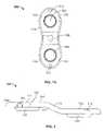
- FIG. 1is a perspective view of a growth control device according to the present teachings
- FIG. 1Ais a top view of the growth control device of FIG. 1 ;
- FIG. 2is an elevated side view of the bone plane of FIG. 1 ;
- FIG. 3is a perspective view of a growth control device according to the present teachings.
- FIG. 3Ais a top view of the growth control device of FIG. 3 ;
- FIG. 4is a perspective view of the growth control device of FIG. 1 shown with a holding device;
- FIG. 4Ais an enlarged detail of FIG. 4 ;
- FIG. 4Bis an enlarged detail of the holding device of FIG. 4 ;
- FIG. 5is a perspective view of the growth control device of FIG. 1 shown with a holding device;
- FIG. 6is an elevated side view of the growth control device of FIG. 1 shown with a targeting device;
- FIG. 7is a perspective view of the growth control device of FIG. 1 shown with a holding and targeting devices;
- FIG. 8is an environmental view showing a growth control device implanted in the femur and a growth control device implanted in the tibia according to the present teachings;
- FIG. 9is an elevated side view of the growth control device of FIG. 1 shown with variable-angle bone fasteners;
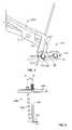
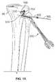
- FIGS. 10-18are views illustrating various aspects of implanting a growth control device in the tibia with associated devices according to the present teachings
- FIG. 19is a perspective view of a growth control device coupled to an extractor according to the present teachings.
- FIG. 19Ais an enlarged detail of a distal end of the extractor of FIG. 19 .
- the present teachingsare illustrated for procedures relating to femur and/or tibia, the present teachings can be used for any long bones in pediatric or other surgery. In particular, the present teaching can be used to correct angular deformities in long bones in pediatric patients.
- the growth control devicecan include one or more bone plates 100 .
- a bone plate 100can have an anatomically contoured stepped or offset profile, as illustrated in FIGS. 1 , 1 A and 2 , or an anatomically contoured humped or arched profile, as illustrated in FIGS. 2 and 3 .
- the growth control devicecan be used to provide gradual correction of an angular deformity in a long bone by restraining one side, medial or lateral, of the growing bone, causing the bone to grow on the opposite side, thereby forcing a natural correction by a non-symmetric corrective bone growth.
- the growth control devicecan include a bone plate 100 which is contoured and profiled for matching the anatomy of the particular bone, and non-locking threaded bone fasteners 150 that can angulate about an axis C perpendicular to the bone plate 100 within a cone of maximum angulation of an angle ⁇ of about 32-degrees between axes C′ and C′′, as shown in FIG. 9 .
- Each bone fastener 150can be cannulated therethrough for receiving a guide wire 300 , and can have a spherically shaped head 152 including a formation for engaging a driver 320 , as shown in FIG. 18 .
- the bone fasteners 150can be low-profile cannulated titanium alloy screws with self-cutting tips and reverse buttress threads to guard against pull out.
- the bone plate 100can have, in a side elevated view, a stepped profile 116 that includes a first level 120 , a second level 122 and an intermediate inclined or ramped portion 118 connecting the first level 120 to the second level, as shown in FIG. 2 .
- the profile 116can be shaped to conform to the anatomic contour of a long bone of a patient and can be provided in various sizes and shapes, including the relative dimensions of the first level 120 , the second level 122 and the intermediate portion 118 , to account for anatomic differences from bone to bone and from patient to patient, including patient's age, gender, and degree of deformity.
- the first level 120 and the second level 122can be disposed in parallel and spaced apart planes.
- the bone plate 100can include first and second (proximal and distal) holes 102 , 104 extending through the thickness of the bone plate 100 from an outward or upper surface 111 to an opposite bone-engaging surface 113 .
- the holes 102 , 104define corresponding inner surfaces 103 , 105 , which are threaded and spherically shaped for receiving threaded fixation bone fasteners 150 having spherically shaped heads 152 , as shown in FIG. 9 .
- the bone plate 100can also include a third or central hole 106 , positioned between the first and second holes 102 , 104 .
- the third hole 106can define a threaded inner surface 107 for engagement with a threaded distal end 408 of a post 400 of a targeting device and/or a threaded distal end 352 of an extractor 350 , as shown in FIGS. 6 , 7 and 19 .
- the bone plate 100can include two smaller end openings or guide holes 112 at the proximal and distal ends of the bone plate 100 for guiding a K-wire or other guide wire 300 therethrough, as shown in FIG. 5 , for example.
- the bone plate 100can also include two pairs of female side notches 110 , i.e., medial and lateral notches 110 at the proximal and distal ends of the bone plate 100 , for engagement with forceps or other holding device 200 , as shown in FIGS. 4 , 4 A, 4 B, for example, and described below.
- the bone plate 100can include first and second washers 130 surrounding the first and second holes 102 , 104 on the bone engaging surface 113 of the bone plate 100 .
- Each washer 130can be unitarily integrated and built-in the bone plate 100 forming a unitary device with the bone plate 100 .
- the washers 130can provide a clearance for the physis of the bone and reduce contact with the periosteum of the bone.
- a bone plate 100 having an intermediate portion 119 in the form of an arch or hump, rather than an offset rampcan be used depending on the anatomical contour of the specific patient or long bone.
- the intermediate portion 119avoids placing bearing load on the physis of the bone or injuring the physis during the correction period, when the bone plate 100 is implanted in a pediatric patient for correcting a non-symmetric growth or other unequal bone growth or deformity.
- the bone plate of FIGS. 3 and 3Ais similar to bone plates of FIGS. 1-2 .
- the profile 116 of ramped bone plate 100 of FIG. 2can match the anatomical features of the proximal tibia 90 before the bone fasteners are implanted through the bone plate 100 . Further, the ramped profile 116 allows parallel placement of bone fasteners 150 through the holes 102 , 104 of the bone plate 100 , as shown in FIG. 8 . Gradual angulation of the bone fasteners 150 relative to the bone plate 100 occurs over a longer period of time before reaching the maximum angulation of the growth control device. The extended period to maximum angulation can reduce the risk of bone fastener fracture, which can be greater when maximum angulation of the bone fastener 150 is reached such that the growth control device of the bone plate 100 and the bone fasteners 150 becomes substantially rigid while bone growth continues.
- the combination of the stepped profile 116 and other features of the bone plate 100 of FIG. 2 with the ability of the bone fasteners 150 to angulate relative to an axis C perpendicular to the bone plate within a cone of angulation of an angle ⁇can provide deformity correction during the physis growth period without closing the physis or completely preventing growth until maximum angulation is reached.
- FIGS. 4 , 4 A, 4 B and 5a holding device 200 for the bone plate 100 in the form of forceps is illustrated.
- the holding device 200has scissor-like gripping handles 216 , first and second arms 212 , 214 pivotably coupled with a pivot pin 210 , and first and second legs (forceps tips) 202 , 204 configured for holding the bone plate 100 from one end, and capturing a guide wire 300 that can pass through the corresponding end opening 122 of the bone plate 100 .
- the distal ends of the forceps legs 202 , 204define a split curved groove or slot 230 , in the form of a pair of slots 230 , between corresponding upper and lower surfaces 232 , 234 .
- a pair of male notches or press pins 240extend from the lower surface 234 substantially perpendicularly to the lower surface 234 and up to or stopping just short of the upper surface 232 of the slot 230 .
- the split slot 230is shaped to receive either end of the bone plate 100 , such that the pins 240 engage the side notches 110 of the bone plate 100 .
- the pins 240can secure the bone plate 100 to the holding device 200 and prevent unintentional shifting of the bone plate 100 during tightening of the bone fasteners 150 .
- the distal ends of the legs 202 , 204also define a split guiding bore 242 for receiving the guide wire 300 that passes through the end hole 112 of the bone plate 100 and between the legs 202 , 204 of the forceps when the bone plate 100 is held in the slot 230 of the forceps 200 , as shown in FIGS. 4A and 4B .
- the first and second legs 202 , 204 of the holding device 200can be contoured and cooperate with the spilt guiding bore 242 to provide an integrated guide for the guide wire 300 along the length of the legs 402 , 404 , as shown in FIG. 4A .
- a targeting device 400can be used for guiding the angulating bone fasteners 150 through the bone plate 100 .
- the targeting device 400can include a support bar or plate 406 having openings for receiving a support post 404 along an axis A and a tubular or cannulated drill guide 402 along an axis B at an angle a of about 16 degrees relative to the axis A, corresponding to a cone of maximum angulation of 32 degrees.
- the drill guide 402can include a proximal end with an engagement formation for driver-assisted placement.
- the support post 402can have a threaded distal end 408 threadably engaging the threaded third hole 106 of the bone plate 100 .
- the extractor 350 illustrated in FIGS. 19 and 19Acan be used as the support post 402 .
- the targeting device 400can be used with the holding device as shown in FIG. 7 .
- the growth control devicecan be provided in the form of a surgical kit including a plurality of bone plates 100 of different sizes and geometries with an arched intermediate portions 119 or a ramped intermediate portion 118 , a holding device 200 , a targeting device 400 with different size drill guides 402 , a plate extractor 350 , various guide wires 300 and drill bits and other instruments, such as an impact trocar, a ratcheting wrench, a torque driver, and the like.
- a guide wire 300can be inserted in the physis (growth plate) of the tibia 90 .
- the bone plate 100as held by the holding device 200 and with proximal and distal drill guides 402 engaging the corresponding first and second holes 102 , 104 of the bone plate 100 , can be passed over the guide wire 300 , such that the guide wire 300 passes through the third hole 106 of the bone plate, as shown in FIGS. 11 and 12 .
- the guide wire 300can inserted proximally or distally off the physis and received through the corresponding proximal or distal end hole 112 of the bone plate 100 , as shown in FIG. 4A .
- Another guide wire 300is inserted into the proximal drill guide 402 , as shown in FIG. 12 , and the bone is drilled with a cannulated drill bit 302 placed over the proximal guide wire 300 , as shown in FIG. 13 .
- An appropriately sized bone fastener 150can be selected and passed over the guide wire 300 using a driver 320 engaging the head 152 of the bone fastener 150 , as shown in FIG. 14 .
- the procedurecan be repeated for the distal bone fastener 150 .
- a distal guide wire 300can inserted through the distal drill guide 402 , as shown in FIG. 15 , and the holding device 200 can be removed, as shown in FIG. 16 .
- a drill holecan be prepared for the distal bone fastener 150 with a drill bit 302 over the distal guide wire 300 , as shown in FIG. 17 , and the distal bone fastener 150 can be passed over the distal guide wire 300 and seated through the bone plate 100 into the tibia 90 with a driver 320 , as shown in FIG. 18 .
- a bone plate 100can be similarly placed on the femur, as shown in FIG. 8 .
- the initial placement of the bone fasteners 150 in each bone plate 100can be such that the bone fasteners are substantially parallel or have a minimum amount of angulation to reduce the risk of breakage, as discussed above.
- the arched or stepped geometry of the bone plate 100permits minimal contact with the lateral physis, as shown in FIG. 8 , and can reduce the risk of pressure necrosis.
- the bone plate 100can be removed with the extractor 350 after the bone fasteners 150 have been unscrewed and removed with a driver 320 .
- the distal end 352 of the extractor 350can include threads 354 engageable to the threaded inner surface 107 of the central hole 106 of the bone plate 100 for capturing and removing the bone plate 100 .
- the distal end 352 of the extractor 150can have a cutting flute 356 for passing through fibrous soft tissue and a curved tip 358 defining a non-invasive radius for avoiding accidental damage to the physis.
Landscapes
- Health & Medical Sciences (AREA)
- Orthopedic Medicine & Surgery (AREA)
- Surgery (AREA)
- Life Sciences & Earth Sciences (AREA)
- Biomedical Technology (AREA)
- Public Health (AREA)
- Veterinary Medicine (AREA)
- Engineering & Computer Science (AREA)
- Nuclear Medicine, Radiotherapy & Molecular Imaging (AREA)
- Heart & Thoracic Surgery (AREA)
- Medical Informatics (AREA)
- Molecular Biology (AREA)
- Animal Behavior & Ethology (AREA)
- General Health & Medical Sciences (AREA)
- Neurology (AREA)
- Dentistry (AREA)
- Oral & Maxillofacial Surgery (AREA)
- Surgical Instruments (AREA)
Abstract
Description
Claims (25)
Priority Applications (5)
| Application Number | Priority Date | Filing Date | Title |
|---|---|---|---|
| US12/166,833US8273111B2 (en) | 2008-07-02 | 2008-07-02 | Growth control device |
| US13/483,231US8801760B2 (en) | 2008-07-02 | 2012-05-30 | Growth control device |
| US29/492,689USD754347S1 (en) | 2008-07-02 | 2014-06-02 | Growth control device |
| US14/456,432US9579134B2 (en) | 2008-07-02 | 2014-08-11 | Growth control device |
| US15/434,277US10130401B2 (en) | 2008-07-02 | 2017-02-16 | Growth control device |
Applications Claiming Priority (1)
| Application Number | Priority Date | Filing Date | Title |
|---|---|---|---|
| US12/166,833US8273111B2 (en) | 2008-07-02 | 2008-07-02 | Growth control device |
Related Child Applications (1)
| Application Number | Title | Priority Date | Filing Date |
|---|---|---|---|
| US13/483,231ContinuationUS8801760B2 (en) | 2008-07-02 | 2012-05-30 | Growth control device |
Publications (2)
| Publication Number | Publication Date |
|---|---|
| US20100004691A1 US20100004691A1 (en) | 2010-01-07 |
| US8273111B2true US8273111B2 (en) | 2012-09-25 |
Family
ID=41464958
Family Applications (5)
| Application Number | Title | Priority Date | Filing Date |
|---|---|---|---|
| US12/166,833Expired - Fee RelatedUS8273111B2 (en) | 2008-07-02 | 2008-07-02 | Growth control device |
| US13/483,231Expired - Fee RelatedUS8801760B2 (en) | 2008-07-02 | 2012-05-30 | Growth control device |
| US29/492,689ActiveUSD754347S1 (en) | 2008-07-02 | 2014-06-02 | Growth control device |
| US14/456,432Expired - Fee RelatedUS9579134B2 (en) | 2008-07-02 | 2014-08-11 | Growth control device |
| US15/434,277Expired - Fee RelatedUS10130401B2 (en) | 2008-07-02 | 2017-02-16 | Growth control device |
Family Applications After (4)
| Application Number | Title | Priority Date | Filing Date |
|---|---|---|---|
| US13/483,231Expired - Fee RelatedUS8801760B2 (en) | 2008-07-02 | 2012-05-30 | Growth control device |
| US29/492,689ActiveUSD754347S1 (en) | 2008-07-02 | 2014-06-02 | Growth control device |
| US14/456,432Expired - Fee RelatedUS9579134B2 (en) | 2008-07-02 | 2014-08-11 | Growth control device |
| US15/434,277Expired - Fee RelatedUS10130401B2 (en) | 2008-07-02 | 2017-02-16 | Growth control device |
Country Status (1)
| Country | Link |
|---|---|
| US (5) | US8273111B2 (en) |
Cited By (14)
| Publication number | Priority date | Publication date | Assignee | Title |
|---|---|---|---|---|
| US20150320453A1 (en)* | 2008-11-07 | 2015-11-12 | Globus Medical, Inc. | Vertical inline plate |
| US9468479B2 (en) | 2013-09-06 | 2016-10-18 | Cardinal Health 247, Inc. | Bone plate |
| USD779065S1 (en) | 2014-10-08 | 2017-02-14 | Nuvasive, Inc. | Anterior cervical bone plate |
| US9579134B2 (en) | 2008-07-02 | 2017-02-28 | Biomet Manufacturing, Llc | Growth control device |
| EP3257457A1 (en) | 2016-06-17 | 2017-12-20 | ORTHOFIX S.r.l. | Internal plate fixation device |
| USD819209S1 (en)* | 2015-08-07 | 2018-05-29 | Paragon 28, Inc. | Calc-slide bone plate |
| IT201700030628A1 (en)* | 2017-03-20 | 2018-09-20 | Orthofix Srl | Improved plaque internal fixation device |
| US20190053909A1 (en)* | 2016-08-30 | 2019-02-21 | Wright Medical Technology, Inc. | Revision total ankle implants |
| USD857899S1 (en)* | 2017-12-08 | 2019-08-27 | Paragon 28, Inc. | Bone plate |
| US10617457B2 (en) | 2016-03-03 | 2020-04-14 | Stryker European Holdings I, Llc | Forceps for handling/holding a mobile wedge plate |
| US11123117B1 (en)* | 2011-11-01 | 2021-09-21 | Nuvasive, Inc. | Surgical fixation system and related methods |
| US11457965B1 (en) | 2021-11-12 | 2022-10-04 | University Of Utah Research Foundation | Rotational guided growth devices, systems, and methods |
| US11571248B2 (en) | 2019-03-19 | 2023-02-07 | Orthoalignment, Llc | Bone implant and method for treating long bone angular deformities |
| US11607323B2 (en) | 2018-10-15 | 2023-03-21 | Howmedica Osteonics Corp. | Patellofemoral trial extractor |
Families Citing this family (37)
| Publication number | Priority date | Publication date | Assignee | Title |
|---|---|---|---|---|
| US8728133B2 (en) | 2009-06-30 | 2014-05-20 | The Penn State Research Foundation | Bone repair system and method |
| US8715326B2 (en)* | 2009-08-28 | 2014-05-06 | Competitive Global Medical, Llc | Distal interphalangeal fusion device and method of use |
| US20110082550A1 (en)* | 2009-10-07 | 2011-04-07 | Yeh An-Shih | Intervertebral fixation device |
| KR200451511Y1 (en)* | 2010-07-20 | 2010-12-17 | 이철규 | Orthodontic Fixture |
| CN101953711B (en)* | 2010-10-15 | 2012-04-18 | 上海交通大学医学院附属新华医院 | Asymmetric 8-shaped steel plate with built-in epiphyseal block and application thereof |
| US8685067B2 (en) | 2010-12-21 | 2014-04-01 | Competitive Global Medical, Llc | Compression plate apparatus |
| DE102011008557B4 (en)* | 2011-01-14 | 2015-02-05 | Stryker Leibinger Gmbh & Co. Kg | Surgical holding instrument for bone plates |
| US9078676B2 (en)* | 2011-09-28 | 2015-07-14 | Depuy (Ireland) | Patella drilling system |
| DE202011107521U1 (en)* | 2011-11-04 | 2011-12-01 | Cival Medical Gmbh | Bone surgical placement instrument and system for applying a bone surgical fastener to a bone plate |
| US10022174B2 (en)* | 2012-06-04 | 2018-07-17 | Depuy Mitek, Llc | Methods and devices for surgical guide pin placement |
| US10231767B2 (en)* | 2013-03-15 | 2019-03-19 | The Penn State Research Foundation | Bone repair system, kit and method |
| AU2014340051A1 (en)* | 2013-10-23 | 2016-06-09 | Extremity Medical Llc | Devices and methods for bone fixation using an intramedullary fixation implant |
| US9987061B2 (en)* | 2014-01-28 | 2018-06-05 | Biomet C.V. | Implant with suspended locking holes |
| US10245088B2 (en) | 2015-01-07 | 2019-04-02 | Treace Medical Concepts, Inc. | Bone plating system and method |
| DE102015001296B4 (en)* | 2015-01-14 | 2018-05-30 | Königsee Implantate GmbH | Implant for temporary Epiphyseodese or Hemiepiphyseodese |
| US10842509B2 (en)* | 2015-02-05 | 2020-11-24 | The Sydney Children's Hospitals Network (Randwick And Westmead) | Orthopaedic device for correction of deformities in a bone |
| WO2016134160A1 (en) | 2015-02-18 | 2016-08-25 | Treace Medical Concepts, Inc. | Bone plating kit for foot and ankle applications |
| WO2016197328A1 (en)* | 2015-06-09 | 2016-12-15 | 佘承鑫 | Fixing bone plate |
| WO2017021762A1 (en)* | 2015-08-06 | 2017-02-09 | Industrias Medicas Sampedro S.A.S. | Bone fixation device for use in guided growth and as a tension band |
| KR101752477B1 (en)* | 2015-12-15 | 2017-07-11 | 문성철 | Palatal expansion appliance |
| EP3184064B1 (en)* | 2015-12-23 | 2019-05-01 | Stryker European Holdings I, LLC | Bone plate with guiding channels |
| US10856919B2 (en)* | 2016-02-22 | 2020-12-08 | Life Spine, Inc. | Lateral spine plate with set screw locking of bone screws |
| EP3257458A1 (en)* | 2016-06-17 | 2017-12-20 | ORTHOFIX S.r.l. | Bone plate for epiphysiodesis |
| AU2017313725B2 (en)* | 2016-08-15 | 2022-09-22 | Triqueue Holdings, Llc | Bone fusion device, system and methods |
| US20180081370A1 (en)* | 2016-09-22 | 2018-03-22 | Robert Bosch Gmbh | Trailer hitch ball detection and location measurement using a rear view camera |
| IT201700002652A1 (en)* | 2017-01-12 | 2018-07-12 | 2B1 S R L | Improved plaque for the synthesis of a bone fracture and kit incorporating this plate. |
| IT201700006369A1 (en)* | 2017-01-20 | 2018-07-20 | Orthofix Srl | Internal plate fixation device |
| CA179380S (en)* | 2017-08-23 | 2019-01-18 | Jjgc Ind E Comercio De Materiais Dentarios S A | Prosthetic component |
| WO2019185104A1 (en) | 2018-03-28 | 2019-10-03 | Elkhawaga Ahmed Mohamed Abou Elainen | The gear dynamic compression plates |
| US11583323B2 (en) | 2018-07-12 | 2023-02-21 | Treace Medical Concepts, Inc. | Multi-diameter bone pin for installing and aligning bone fixation plate while minimizing bone damage |
| EP3856042B1 (en)* | 2018-09-27 | 2025-07-02 | Triqueue Holdings, Llc | Implant systems, plates, bone fusion systems |
| WO2020107072A1 (en)* | 2018-11-28 | 2020-06-04 | The Sydney Children's Hospitals Network (Randwick And Westmead) | Guided growth device and method |
| KR102210941B1 (en)* | 2019-01-10 | 2021-02-02 | 충남대학교산학협력단 | A animal bone plate for being implanted into the distolateral surfacief femur in distal femur osteotomy surgray |
| DE102019115476A1 (en) | 2019-06-07 | 2020-12-10 | TADMAN GmbH | Implant plate device |
| US11890039B1 (en) | 2019-09-13 | 2024-02-06 | Treace Medical Concepts, Inc. | Multi-diameter K-wire for orthopedic applications |
| USD1022194S1 (en)* | 2019-10-04 | 2024-04-09 | Shukla Medical | Strike plate for a surgical instrument |
| US20230200876A1 (en)* | 2020-05-07 | 2023-06-29 | ExsoMed Corporation | Wrist fusion system and delivery tool |
Citations (29)
| Publication number | Priority date | Publication date | Assignee | Title |
|---|---|---|---|---|
| US2511051A (en) | 1946-06-19 | 1950-06-13 | Dzus William | Fastening device |
| US4905679A (en) | 1988-02-22 | 1990-03-06 | M P Operation, Inc. | Bone fracture reduction device and method of internal fixation of bone fractures |
| US5006120A (en) | 1989-10-10 | 1991-04-09 | Carter Peter R | Distal radial fracture set and method for repairing distal radial fractures |
| US5423826A (en) | 1993-02-05 | 1995-06-13 | Danek Medical, Inc. | Anterior cervical plate holder/drill guide and method of use |
| US5531751A (en) | 1993-06-02 | 1996-07-02 | Gerhard Weber | Aiming tube assembly |
| US5752958A (en) | 1997-04-02 | 1998-05-19 | Wellisz; Tadeusz Z. | Bone fixation plate |
| US5810822A (en) | 1994-04-27 | 1998-09-22 | Mortier; Jean-Pierre | Apparatus for correcting long bone deformation |
| US5810823A (en) | 1994-09-12 | 1998-09-22 | Synthes (U.S.A.) | Osteosynthetic bone plate and lock washer |
| US5827286A (en) | 1997-02-14 | 1998-10-27 | Incavo; Stephen J. | Incrementally adjustable tibial osteotomy fixation device and method |
| US5921988A (en) | 1996-11-08 | 1999-07-13 | Proseal | Installation instrument for a blade suture clip for ostelogical removal for the treatment of inflammation of the knee joint |
| US5968046A (en) | 1998-06-04 | 1999-10-19 | Smith & Nephew, Inc. | Provisional fixation pin |
| US5984925A (en) | 1997-07-30 | 1999-11-16 | Cross Medical Products, Inc. | Longitudinally adjustable bone plates and method for use thereof |
| US6379364B1 (en) | 2000-04-28 | 2002-04-30 | Synthes (Usa) | Dual drill guide for a locking bone plate |
| US6610062B2 (en) | 2000-02-16 | 2003-08-26 | Ebi, L.P. | Method and system for spinal fixation |
| US20040102777A1 (en)* | 2002-11-19 | 2004-05-27 | Huebner Randall J. | Deformable bone plates |
| US20040111089A1 (en) | 2002-12-04 | 2004-06-10 | Stevens Peter M. | Bone alignment implant and method of use |
| US20040210228A1 (en)* | 2001-10-29 | 2004-10-21 | Carl-Goran Hagert | System for fixation of fractures comprising an elastic chassis |
| US6821278B2 (en) | 2000-06-26 | 2004-11-23 | Synthes Ag Chur | Bone plate |
| US20050015092A1 (en) | 2003-07-16 | 2005-01-20 | Rathbun David S. | Plating system with multiple function drill guide |
| US20050080421A1 (en)* | 1999-09-13 | 2005-04-14 | Synthes (Usa) | Bone plating system |
| US20050149027A1 (en)* | 2000-06-26 | 2005-07-07 | Stryker Spine | Bone screw retaining system |
| US6966911B2 (en) | 2002-01-22 | 2005-11-22 | Jorge Abel Groiso | Bone staple and methods for correcting bone deficiencies by controllably suppressing and/or inducing the growth of the epiphyseal plate |
| US7011665B2 (en) | 2002-07-22 | 2006-03-14 | Sdgi Holdings, Inc. | Guide assembly for engaging a bone plate to a bony segment |
| US7052499B2 (en) | 1998-02-18 | 2006-05-30 | Walter Lorenz Surgical, Inc. | Method and apparatus for bone fracture fixation |
| US20060142767A1 (en) | 2004-12-27 | 2006-06-29 | Green Daniel W | Orthopedic device and method for correcting angular bone deformity |
| US7081119B2 (en) | 2003-08-01 | 2006-07-25 | Hfsc Company | Drill guide assembly for a bone fixation device |
| US20060167459A1 (en) | 2002-01-22 | 2006-07-27 | Groiso Jorge A | Bone staple and methods for correcting spine disorders |
| US20080147125A1 (en)* | 2006-12-12 | 2008-06-19 | Dennis Colleran | Active Settling Plate and Method of Use |
| US20080161861A1 (en)* | 2006-10-17 | 2008-07-03 | Acumed Llc | Bone fixation with a strut-stabilized bone plate |
Family Cites Families (10)
| Publication number | Priority date | Publication date | Assignee | Title |
|---|---|---|---|---|
| US6315779B1 (en)* | 1999-04-16 | 2001-11-13 | Sdgi Holdings, Inc. | Multi-axial bone anchor system |
| US6706046B2 (en)* | 2000-02-01 | 2004-03-16 | Hand Innovations, Inc. | Intramedullary fixation device for metaphyseal long bone fractures and methods of using the same |
| USD480141S1 (en)* | 2000-06-01 | 2003-09-30 | Steve Benirschke | Bone plate |
| US8118846B2 (en)* | 2005-01-28 | 2012-02-21 | Orthohelix Surgical Designs, Inc. | Orthopedic plates for use in clavicle repair and methods for their use |
| USD520637S1 (en)* | 2005-06-16 | 2006-05-09 | Orthohelix Surgical Designs, Inc. | Orthopedic plate |
| US8100952B2 (en)* | 2005-12-22 | 2012-01-24 | Anthem Orthopaedics Llc | Drug delivering bone plate and method and targeting device for use therewith |
| US8273111B2 (en) | 2008-07-02 | 2012-09-25 | Ebi, Llc | Growth control device |
| USD630750S1 (en)* | 2009-09-17 | 2011-01-11 | Upex Holdings, Llc | Radial head/neck fracture fixation plate |
| USD648027S1 (en)* | 2010-02-09 | 2011-11-01 | Tornier, Inc. | Prosthesis |
| USD699351S1 (en)* | 2013-01-04 | 2014-02-11 | D. L. P. | Osteosynthesis plate |
- 2008
- 2008-07-02USUS12/166,833patent/US8273111B2/ennot_activeExpired - Fee Related
- 2012
- 2012-05-30USUS13/483,231patent/US8801760B2/ennot_activeExpired - Fee Related
- 2014
- 2014-06-02USUS29/492,689patent/USD754347S1/enactiveActive
- 2014-08-11USUS14/456,432patent/US9579134B2/ennot_activeExpired - Fee Related
- 2017
- 2017-02-16USUS15/434,277patent/US10130401B2/ennot_activeExpired - Fee Related
Patent Citations (32)
| Publication number | Priority date | Publication date | Assignee | Title |
|---|---|---|---|---|
| US2511051A (en) | 1946-06-19 | 1950-06-13 | Dzus William | Fastening device |
| US4905679A (en) | 1988-02-22 | 1990-03-06 | M P Operation, Inc. | Bone fracture reduction device and method of internal fixation of bone fractures |
| US5006120A (en) | 1989-10-10 | 1991-04-09 | Carter Peter R | Distal radial fracture set and method for repairing distal radial fractures |
| US5423826A (en) | 1993-02-05 | 1995-06-13 | Danek Medical, Inc. | Anterior cervical plate holder/drill guide and method of use |
| US5531751A (en) | 1993-06-02 | 1996-07-02 | Gerhard Weber | Aiming tube assembly |
| US5810822A (en) | 1994-04-27 | 1998-09-22 | Mortier; Jean-Pierre | Apparatus for correcting long bone deformation |
| US5810823A (en) | 1994-09-12 | 1998-09-22 | Synthes (U.S.A.) | Osteosynthetic bone plate and lock washer |
| US5921988A (en) | 1996-11-08 | 1999-07-13 | Proseal | Installation instrument for a blade suture clip for ostelogical removal for the treatment of inflammation of the knee joint |
| US5827286A (en) | 1997-02-14 | 1998-10-27 | Incavo; Stephen J. | Incrementally adjustable tibial osteotomy fixation device and method |
| US5752958A (en) | 1997-04-02 | 1998-05-19 | Wellisz; Tadeusz Z. | Bone fixation plate |
| US6364881B1 (en) | 1997-07-30 | 2002-04-02 | Interpore Cross International | Longitudinally adjustable bone plates and method for use thereof |
| US5984925A (en) | 1997-07-30 | 1999-11-16 | Cross Medical Products, Inc. | Longitudinally adjustable bone plates and method for use thereof |
| US7052499B2 (en) | 1998-02-18 | 2006-05-30 | Walter Lorenz Surgical, Inc. | Method and apparatus for bone fracture fixation |
| US5968046A (en) | 1998-06-04 | 1999-10-19 | Smith & Nephew, Inc. | Provisional fixation pin |
| US20050080421A1 (en)* | 1999-09-13 | 2005-04-14 | Synthes (Usa) | Bone plating system |
| US6610062B2 (en) | 2000-02-16 | 2003-08-26 | Ebi, L.P. | Method and system for spinal fixation |
| US6379364B1 (en) | 2000-04-28 | 2002-04-30 | Synthes (Usa) | Dual drill guide for a locking bone plate |
| US20050149027A1 (en)* | 2000-06-26 | 2005-07-07 | Stryker Spine | Bone screw retaining system |
| US6821278B2 (en) | 2000-06-26 | 2004-11-23 | Synthes Ag Chur | Bone plate |
| US20040210228A1 (en)* | 2001-10-29 | 2004-10-21 | Carl-Goran Hagert | System for fixation of fractures comprising an elastic chassis |
| US6966911B2 (en) | 2002-01-22 | 2005-11-22 | Jorge Abel Groiso | Bone staple and methods for correcting bone deficiencies by controllably suppressing and/or inducing the growth of the epiphyseal plate |
| US20060167459A1 (en) | 2002-01-22 | 2006-07-27 | Groiso Jorge A | Bone staple and methods for correcting spine disorders |
| US7011665B2 (en) | 2002-07-22 | 2006-03-14 | Sdgi Holdings, Inc. | Guide assembly for engaging a bone plate to a bony segment |
| US20040102777A1 (en)* | 2002-11-19 | 2004-05-27 | Huebner Randall J. | Deformable bone plates |
| US20040111089A1 (en) | 2002-12-04 | 2004-06-10 | Stevens Peter M. | Bone alignment implant and method of use |
| US7811312B2 (en) | 2002-12-04 | 2010-10-12 | Morphographics, Lc | Bone alignment implant and method of use |
| US8133230B2 (en) | 2002-12-04 | 2012-03-13 | Peter M. Stevens | Bone alignment implant and method of use |
| US20050015092A1 (en) | 2003-07-16 | 2005-01-20 | Rathbun David S. | Plating system with multiple function drill guide |
| US7081119B2 (en) | 2003-08-01 | 2006-07-25 | Hfsc Company | Drill guide assembly for a bone fixation device |
| US20060142767A1 (en) | 2004-12-27 | 2006-06-29 | Green Daniel W | Orthopedic device and method for correcting angular bone deformity |
| US20080161861A1 (en)* | 2006-10-17 | 2008-07-03 | Acumed Llc | Bone fixation with a strut-stabilized bone plate |
| US20080147125A1 (en)* | 2006-12-12 | 2008-06-19 | Dennis Colleran | Active Settling Plate and Method of Use |
Non-Patent Citations (3)
| Title |
|---|
| Biomet® Growth Control Plating System, Biomet Trauma, Pediatric Orthopedics, Copyright 2008 Biomet, Inc. |
| Biomet® Growth Control Plating System, Pre-Launch Surgical Technique, Biomet Trauma, Pediatric Orthopedics, Copyright 2008 Biomet, Inc. |
| Staple Fixation System, Implants, Instruments, Applications, Stryker Osteosynthesis, Copyright© 2007 Stryker. |
Cited By (27)
| Publication number | Priority date | Publication date | Assignee | Title |
|---|---|---|---|---|
| US9579134B2 (en) | 2008-07-02 | 2017-02-28 | Biomet Manufacturing, Llc | Growth control device |
| US10130401B2 (en) | 2008-07-02 | 2018-11-20 | Biomet Manufacturing, Llc | Growth control device |
| US20150320453A1 (en)* | 2008-11-07 | 2015-11-12 | Globus Medical, Inc. | Vertical inline plate |
| US11123117B1 (en)* | 2011-11-01 | 2021-09-21 | Nuvasive, Inc. | Surgical fixation system and related methods |
| US9468479B2 (en) | 2013-09-06 | 2016-10-18 | Cardinal Health 247, Inc. | Bone plate |
| USD798455S1 (en) | 2014-10-08 | 2017-09-26 | Nuvasive, Inc. | Anterior cervical bone plate |
| USD779065S1 (en) | 2014-10-08 | 2017-02-14 | Nuvasive, Inc. | Anterior cervical bone plate |
| USD819209S1 (en)* | 2015-08-07 | 2018-05-29 | Paragon 28, Inc. | Calc-slide bone plate |
| US11464554B2 (en) | 2016-03-03 | 2022-10-11 | Stryker European Operations Holdings Llc | Forceps for handling/holding a mobile wedge plate |
| US10617457B2 (en) | 2016-03-03 | 2020-04-14 | Stryker European Holdings I, Llc | Forceps for handling/holding a mobile wedge plate |
| IL262999B (en)* | 2016-06-17 | 2022-10-01 | Orthofix Srl | Internal plate fixation device |
| EP3257457A1 (en) | 2016-06-17 | 2017-12-20 | ORTHOFIX S.r.l. | Internal plate fixation device |
| WO2017215896A1 (en) | 2016-06-17 | 2017-12-21 | Orthofix S.R.L. | Internal plate fixation device |
| US11006987B2 (en) | 2016-06-17 | 2021-05-18 | Orthofix S.R.L. | Internal plate fixation device |
| IL262999B2 (en)* | 2016-06-17 | 2023-02-01 | Orthofix Srl | Internal plate fixation device |
| US20190053909A1 (en)* | 2016-08-30 | 2019-02-21 | Wright Medical Technology, Inc. | Revision total ankle implants |
| IT201700030628A1 (en)* | 2017-03-20 | 2018-09-20 | Orthofix Srl | Improved plaque internal fixation device |
| US11406434B2 (en) | 2017-03-20 | 2022-08-09 | Orthofix S.R.L. | Bone plate |
| US11986226B2 (en) | 2017-03-20 | 2024-05-21 | Orthofix S.R.L. | Bone plate |
| WO2018172113A1 (en) | 2017-03-20 | 2018-09-27 | Orthofix S.R.L. | Bone plate |
| USD857899S1 (en)* | 2017-12-08 | 2019-08-27 | Paragon 28, Inc. | Bone plate |
| US11712275B2 (en) | 2017-12-08 | 2023-08-01 | Paragon 28, Inc. | Bone fixation assembly, implants and methods of use |
| US20240016527A1 (en)* | 2017-12-08 | 2024-01-18 | Paragon 28, Inc. | Bone fixation assembly, implants and methods of use |
| US12290294B2 (en)* | 2017-12-08 | 2025-05-06 | Paragon 28, Inc. | Bone fixation assembly, implants and methods of use |
| US11607323B2 (en) | 2018-10-15 | 2023-03-21 | Howmedica Osteonics Corp. | Patellofemoral trial extractor |
| US11571248B2 (en) | 2019-03-19 | 2023-02-07 | Orthoalignment, Llc | Bone implant and method for treating long bone angular deformities |
| US11457965B1 (en) | 2021-11-12 | 2022-10-04 | University Of Utah Research Foundation | Rotational guided growth devices, systems, and methods |
Also Published As
| Publication number | Publication date |
|---|---|
| US20120239040A1 (en) | 2012-09-20 |
| US8801760B2 (en) | 2014-08-12 |
| USD754347S1 (en) | 2016-04-19 |
| US20170224396A1 (en) | 2017-08-10 |
| US20150032166A1 (en) | 2015-01-29 |
| US9579134B2 (en) | 2017-02-28 |
| US10130401B2 (en) | 2018-11-20 |
| US20100004691A1 (en) | 2010-01-07 |
Similar Documents
| Publication | Publication Date | Title |
|---|---|---|
| US10130401B2 (en) | Growth control device | |
| US10278750B2 (en) | Method of stabilizing a fracture at a metaphysis defining a concave articular surface | |
| US20250241694A1 (en) | Bone fixation assembly, implants and methods of use | |
| JP5868923B2 (en) | Distal tibial plate fixation device | |
| US6793659B2 (en) | Intramedullary rod for wrist fixation | |
| US6755831B2 (en) | Wrist surgery devices and techniques | |
| US20030153918A1 (en) | Volar fixation plate | |
| US10028737B2 (en) | Pelvic cable solution | |
| US8460343B2 (en) | Intramedullary tubular bone fixation | |
| KR20150126965A (en) | Bone repair system, kit and method | |
| US8357162B2 (en) | Intramedullary mandibular condyle implants and method for application of the same | |
| CN107223040B (en) | Intramedullary fixation device and system for use in hip and femur fracture surgery | |
| WO2016038456A2 (en) | System and method of soft tissue anchoring to metaphyseal bone plate | |
| CN109998656A (en) | Vertebral pedicle nail fixer for cervical vertebrae, fixed system and fixing means |
Legal Events
| Date | Code | Title | Description |
|---|---|---|---|
| AS | Assignment | Owner name:EBI, LLC, NEW JERSEY Free format text:ASSIGNMENT OF ASSIGNORS INTEREST;ASSIGNORS:AMATO, MATTHEW F.;WALULIK, STEPHEN B.;SIGNING DATES FROM 20080708 TO 20080723;REEL/FRAME:021285/0588 Owner name:EBI, LLC, NEW JERSEY Free format text:ASSIGNMENT OF ASSIGNORS INTEREST;ASSIGNORS:AMATO, MATTHEW F.;WALULIK, STEPHEN B.;REEL/FRAME:021285/0588;SIGNING DATES FROM 20080708 TO 20080723 | |
| AS | Assignment | Owner name:BANK OF AMERICA, N.A., AS ADMINISTRATIVE AGENT FOR Free format text:SECURITY AGREEMENT;ASSIGNORS:LVB ACQUISITION, INC.;BIOMET, INC.;BIOMET 3I, LLC;AND OTHERS;REEL/FRAME:023505/0241 Effective date:20091111 | |
| STCF | Information on status: patent grant | Free format text:PATENTED CASE | |
| CC | Certificate of correction | ||
| AS | Assignment | Owner name:BIOMET MANUFACTURING, LLC, INDIANA Free format text:ASSIGNMENT OF ASSIGNORS INTEREST;ASSIGNOR:EBI, LLC;REEL/FRAME:031307/0797 Effective date:20130925 | |
| AS | Assignment | Owner name:BIOMET, INC., INDIANA Free format text:RELEASE OF SECURITY INTEREST IN PATENTS RECORDED AT REEL 023505/ FRAME 0241;ASSIGNOR:BANK OF AMERICA, N.A., AS ADMINISTRATIVE AGENT;REEL/FRAME:037155/0082 Effective date:20150624 Owner name:BIOMET EUROPE LTD., INDIANA Free format text:RELEASE OF SECURITY INTEREST IN PATENTS RECORDED AT REEL 023505/ FRAME 0241;ASSIGNOR:BANK OF AMERICA, N.A., AS ADMINISTRATIVE AGENT;REEL/FRAME:037155/0082 Effective date:20150624 Owner name:BIOMET BIOLOGICS, LLC., INDIANA Free format text:RELEASE OF SECURITY INTEREST IN PATENTS RECORDED AT REEL 023505/ FRAME 0241;ASSIGNOR:BANK OF AMERICA, N.A., AS ADMINISTRATIVE AGENT;REEL/FRAME:037155/0082 Effective date:20150624 Owner name:BIOMET MICROFIXATION, LLC, FLORIDA Free format text:RELEASE OF SECURITY INTEREST IN PATENTS RECORDED AT REEL 023505/ FRAME 0241;ASSIGNOR:BANK OF AMERICA, N.A., AS ADMINISTRATIVE AGENT;REEL/FRAME:037155/0082 Effective date:20150624 Owner name:ELECTR-OBIOLOGY, LLC, INDIANA Free format text:RELEASE OF SECURITY INTEREST IN PATENTS RECORDED AT REEL 023505/ FRAME 0241;ASSIGNOR:BANK OF AMERICA, N.A., AS ADMINISTRATIVE AGENT;REEL/FRAME:037155/0082 Effective date:20150624 Owner name:EBI HOLDINGS, LLC, INDIANA Free format text:RELEASE OF SECURITY INTEREST IN PATENTS RECORDED AT REEL 023505/ FRAME 0241;ASSIGNOR:BANK OF AMERICA, N.A., AS ADMINISTRATIVE AGENT;REEL/FRAME:037155/0082 Effective date:20150624 Owner name:BIOMET SPORTS MEDICINE, LLC, INDIANA Free format text:RELEASE OF SECURITY INTEREST IN PATENTS RECORDED AT REEL 023505/ FRAME 0241;ASSIGNOR:BANK OF AMERICA, N.A., AS ADMINISTRATIVE AGENT;REEL/FRAME:037155/0082 Effective date:20150624 Owner name:BIOMET FLORIDA SERVICES, LLC, INDIANA Free format text:RELEASE OF SECURITY INTEREST IN PATENTS RECORDED AT REEL 023505/ FRAME 0241;ASSIGNOR:BANK OF AMERICA, N.A., AS ADMINISTRATIVE AGENT;REEL/FRAME:037155/0082 Effective date:20150624 Owner name:BIOMET INTERNATIONAL LTD., INDIANA Free format text:RELEASE OF SECURITY INTEREST IN PATENTS RECORDED AT REEL 023505/ FRAME 0241;ASSIGNOR:BANK OF AMERICA, N.A., AS ADMINISTRATIVE AGENT;REEL/FRAME:037155/0082 Effective date:20150624 Owner name:BIOMET HOLDINGS LTD., INDIANA Free format text:RELEASE OF SECURITY INTEREST IN PATENTS RECORDED AT REEL 023505/ FRAME 0241;ASSIGNOR:BANK OF AMERICA, N.A., AS ADMINISTRATIVE AGENT;REEL/FRAME:037155/0082 Effective date:20150624 Owner name:EBI MEDICAL SYSTEMS, LLC, INDIANA Free format text:RELEASE OF SECURITY INTEREST IN PATENTS RECORDED AT REEL 023505/ FRAME 0241;ASSIGNOR:BANK OF AMERICA, N.A., AS ADMINISTRATIVE AGENT;REEL/FRAME:037155/0082 Effective date:20150624 Owner name:BIOMET LEASING, INC., INDIANA Free format text:RELEASE OF SECURITY INTEREST IN PATENTS RECORDED AT REEL 023505/ FRAME 0241;ASSIGNOR:BANK OF AMERICA, N.A., AS ADMINISTRATIVE AGENT;REEL/FRAME:037155/0082 Effective date:20150624 Owner name:LVB ACQUISITION, INC., INDIANA Free format text:RELEASE OF SECURITY INTEREST IN PATENTS RECORDED AT REEL 023505/ FRAME 0241;ASSIGNOR:BANK OF AMERICA, N.A., AS ADMINISTRATIVE AGENT;REEL/FRAME:037155/0082 Effective date:20150624 Owner name:EBI, LLC, INDIANA Free format text:RELEASE OF SECURITY INTEREST IN PATENTS RECORDED AT REEL 023505/ FRAME 0241;ASSIGNOR:BANK OF AMERICA, N.A., AS ADMINISTRATIVE AGENT;REEL/FRAME:037155/0082 Effective date:20150624 Owner name:BIOMET TRAVEL, INC., INDIANA Free format text:RELEASE OF SECURITY INTEREST IN PATENTS RECORDED AT REEL 023505/ FRAME 0241;ASSIGNOR:BANK OF AMERICA, N.A., AS ADMINISTRATIVE AGENT;REEL/FRAME:037155/0082 Effective date:20150624 Owner name:KIRSCHNER MEDICAL CORPORATION, INDIANA Free format text:RELEASE OF SECURITY INTEREST IN PATENTS RECORDED AT REEL 023505/ FRAME 0241;ASSIGNOR:BANK OF AMERICA, N.A., AS ADMINISTRATIVE AGENT;REEL/FRAME:037155/0082 Effective date:20150624 Owner name:INTERPORE SPINE, LTD., CALIFORNIA Free format text:RELEASE OF SECURITY INTEREST IN PATENTS RECORDED AT REEL 023505/ FRAME 0241;ASSIGNOR:BANK OF AMERICA, N.A., AS ADMINISTRATIVE AGENT;REEL/FRAME:037155/0082 Effective date:20150624 Owner name:INTERPORE CROSS INTERNATIONAL, LLC, CALIFORNIA Free format text:RELEASE OF SECURITY INTEREST IN PATENTS RECORDED AT REEL 023505/ FRAME 0241;ASSIGNOR:BANK OF AMERICA, N.A., AS ADMINISTRATIVE AGENT;REEL/FRAME:037155/0082 Effective date:20150624 Owner name:BIOMET 3I, LLC, FLORIDA Free format text:RELEASE OF SECURITY INTEREST IN PATENTS RECORDED AT REEL 023505/ FRAME 0241;ASSIGNOR:BANK OF AMERICA, N.A., AS ADMINISTRATIVE AGENT;REEL/FRAME:037155/0082 Effective date:20150624 Owner name:BIOMET MANUFACTURING CORPORATION, INDIANA Free format text:RELEASE OF SECURITY INTEREST IN PATENTS RECORDED AT REEL 023505/ FRAME 0241;ASSIGNOR:BANK OF AMERICA, N.A., AS ADMINISTRATIVE AGENT;REEL/FRAME:037155/0082 Effective date:20150624 Owner name:BIOLECTRON, INC., INDIANA Free format text:RELEASE OF SECURITY INTEREST IN PATENTS RECORDED AT REEL 023505/ FRAME 0241;ASSIGNOR:BANK OF AMERICA, N.A., AS ADMINISTRATIVE AGENT;REEL/FRAME:037155/0082 Effective date:20150624 Owner name:IMPLANT INNOVATIONS HOLDINGS, LLC, INDIANA Free format text:RELEASE OF SECURITY INTEREST IN PATENTS RECORDED AT REEL 023505/ FRAME 0241;ASSIGNOR:BANK OF AMERICA, N.A., AS ADMINISTRATIVE AGENT;REEL/FRAME:037155/0082 Effective date:20150624 Owner name:CROSS MEDICAL PRODUCTS, LLC, CALIFORNIA Free format text:RELEASE OF SECURITY INTEREST IN PATENTS RECORDED AT REEL 023505/ FRAME 0241;ASSIGNOR:BANK OF AMERICA, N.A., AS ADMINISTRATIVE AGENT;REEL/FRAME:037155/0082 Effective date:20150624 Owner name:BIOMET FAIR LAWN LLC, NEW JERSEY Free format text:RELEASE OF SECURITY INTEREST IN PATENTS RECORDED AT REEL 023505/ FRAME 0241;ASSIGNOR:BANK OF AMERICA, N.A., AS ADMINISTRATIVE AGENT;REEL/FRAME:037155/0082 Effective date:20150624 Owner name:BIOMET ORTHOPEDICS, LLC, INDIANA Free format text:RELEASE OF SECURITY INTEREST IN PATENTS RECORDED AT REEL 023505/ FRAME 0241;ASSIGNOR:BANK OF AMERICA, N.A., AS ADMINISTRATIVE AGENT;REEL/FRAME:037155/0082 Effective date:20150624 | |
| FPAY | Fee payment | Year of fee payment:4 | |
| FEPP | Fee payment procedure | Free format text:PAYER NUMBER DE-ASSIGNED (ORIGINAL EVENT CODE: RMPN); ENTITY STATUS OF PATENT OWNER: LARGE ENTITY Free format text:PAYOR NUMBER ASSIGNED (ORIGINAL EVENT CODE: ASPN); ENTITY STATUS OF PATENT OWNER: LARGE ENTITY | |
| FEPP | Fee payment procedure | Free format text:MAINTENANCE FEE REMINDER MAILED (ORIGINAL EVENT CODE: REM.); ENTITY STATUS OF PATENT OWNER: LARGE ENTITY | |
| LAPS | Lapse for failure to pay maintenance fees | Free format text:PATENT EXPIRED FOR FAILURE TO PAY MAINTENANCE FEES (ORIGINAL EVENT CODE: EXP.); ENTITY STATUS OF PATENT OWNER: LARGE ENTITY | |
| STCH | Information on status: patent discontinuation | Free format text:PATENT EXPIRED DUE TO NONPAYMENT OF MAINTENANCE FEES UNDER 37 CFR 1.362 | |
| FP | Lapsed due to failure to pay maintenance fee | Effective date:20200925 |