US8273094B2 - Puncture locating device - Google Patents
Puncture locating deviceDownload PDFInfo
- Publication number
- US8273094B2 US8273094B2US11/131,120US13112005AUS8273094B2US 8273094 B2US8273094 B2US 8273094B2US 13112005 AUS13112005 AUS 13112005AUS 8273094 B2US8273094 B2US 8273094B2
- Authority
- US
- United States
- Prior art keywords
- side port
- tubular member
- inner bore
- extrudable
- vascular
- Prior art date
- Legal status (The legal status is an assumption and is not a legal conclusion. Google has not performed a legal analysis and makes no representation as to the accuracy of the status listed.)
- Expired - Fee Related, expires
Links
- 238000000034methodMethods0.000claimsabstractdescription31
- 210000004204blood vesselAnatomy0.000claimsabstractdescription8
- 230000002792vascularEffects0.000claimsdescription66
- 238000003780insertionMethods0.000claimsdescription57
- 230000037431insertionEffects0.000claimsdescription57
- 230000006835compressionEffects0.000claimsdescription11
- 238000007906compressionMethods0.000claimsdescription11
- 230000001154acute effectEffects0.000claimsdescription8
- 238000004519manufacturing processMethods0.000claimsdescription7
- 239000013013elastic materialSubstances0.000claimsdescription5
- HLXZNVUGXRDIFK-UHFFFAOYSA-Nnickel titaniumChemical compound[Ti].[Ti].[Ti].[Ti].[Ti].[Ti].[Ti].[Ti].[Ti].[Ti].[Ti].[Ni].[Ni].[Ni].[Ni].[Ni].[Ni].[Ni].[Ni].[Ni].[Ni].[Ni].[Ni].[Ni].[Ni]HLXZNVUGXRDIFK-UHFFFAOYSA-N0.000claimsdescription5
- 229910001000nickel titaniumInorganic materials0.000claimsdescription5
- 238000001125extrusionMethods0.000claimsdescription4
- 238000005452bendingMethods0.000claimsdescription2
- 230000000694effectsEffects0.000claims1
- 210000001367arteryAnatomy0.000description19
- 239000000463materialSubstances0.000description4
- 239000008280bloodSubstances0.000description3
- 210000004369bloodAnatomy0.000description3
- 238000007789sealingMethods0.000description3
- 230000000740bleeding effectEffects0.000description2
- 230000007246mechanismEffects0.000description2
- 230000003313weakening effectEffects0.000description2
- 206010003210ArteriosclerosisDiseases0.000description1
- 239000000853adhesiveSubstances0.000description1
- 230000001070adhesive effectEffects0.000description1
- 208000011775arteriosclerosis diseaseDiseases0.000description1
- 210000001105femoral arteryAnatomy0.000description1
- 239000012530fluidSubstances0.000description1
- 230000023597hemostasisEffects0.000description1
- 238000012986modificationMethods0.000description1
- 230000004048modificationEffects0.000description1
- 230000008569processEffects0.000description1
- 230000004044responseEffects0.000description1
- 238000001356surgical procedureMethods0.000description1
- 208000019553vascular diseaseDiseases0.000description1
- 230000000007visual effectEffects0.000description1
- 238000003466weldingMethods0.000description1
Images


Classifications
- A—HUMAN NECESSITIES
- A61—MEDICAL OR VETERINARY SCIENCE; HYGIENE
- A61B—DIAGNOSIS; SURGERY; IDENTIFICATION
- A61B17/00—Surgical instruments, devices or methods
- A61B17/0057—Implements for plugging an opening in the wall of a hollow or tubular organ, e.g. for sealing a vessel puncture or closing a cardiac septal defect
- A61B2017/00672—Locating means therefor, e.g. bleed back lumen
- A—HUMAN NECESSITIES
- A61—MEDICAL OR VETERINARY SCIENCE; HYGIENE
- A61B—DIAGNOSIS; SURGERY; IDENTIFICATION
- A61B17/00—Surgical instruments, devices or methods
- A61B2017/00831—Material properties
- A61B2017/00867—Material properties shape memory effect
- A—HUMAN NECESSITIES
- A61—MEDICAL OR VETERINARY SCIENCE; HYGIENE
- A61B—DIAGNOSIS; SURGERY; IDENTIFICATION
- A61B90/00—Instruments, implements or accessories specially adapted for surgery or diagnosis and not covered by any of the groups A61B1/00 - A61B50/00, e.g. for luxation treatment or for protecting wound edges
- A61B90/03—Automatic limiting or abutting means, e.g. for safety
- A61B2090/033—Abutting means, stops, e.g. abutting on tissue or skin
- A—HUMAN NECESSITIES
- A61—MEDICAL OR VETERINARY SCIENCE; HYGIENE
- A61B—DIAGNOSIS; SURGERY; IDENTIFICATION
- A61B90/00—Instruments, implements or accessories specially adapted for surgery or diagnosis and not covered by any of the groups A61B1/00 - A61B50/00, e.g. for luxation treatment or for protecting wound edges
- A61B90/03—Automatic limiting or abutting means, e.g. for safety
Definitions
- This inventionrelates generally to medical devices and more particularly to devices and methods for locating punctures or incisions in an internal tissue wall.
- vascular diseasesuch as arteriosclerosis
- an instrumente.g., a balloon or other type of catheter
- Such proceduresusually involve the percutaneous puncture of the artery so that an insertion sheath can be placed in the artery.
- the insertion sheathenables the introduction of other instruments (e.g., a catheter) to an operative position within the vascular system.
- Intravascular and intraluminal proceduresoften include instruments of certain dimensions that must be precisely located with respect to the percutaneous puncture.
- the relative position of the various instruments with respect to the puncture in the arterymust be known by an operator in order to properly conduct the intravascular procedure.
- vascular closure devicessuch as those described in U.S. Pat. Nos. 6,179,863; 6,090,130; and 6,045,569, which are hereby incorporated by this reference.
- Typical closure devicessuch as the ones described in the above-mentioned patents place a sealing plug at the tissue puncture site.
- the closure devicesmust be in a proper position relative to the puncture in order to place the sealing plug. If the location of the puncture relative to the closure device is not precisely known, the sealing plug may not be placed at a location conducive to effecting hemostasis of the puncture.
- location of the puncture within an arteryis determined by inserting the closure device and/or an insertion sheath into the artery until blood enters a lumen in the closure device or insertion sheath. As blood exits the lumen through a drip hole in the closure device or insertion sheath, the operator has visual indication of the location of the closure device. The insertion sheath and/or the closure device may then be retracted a certain distance indicated by markings on the insertion sheath to properly locate the closure device relative to the puncture.
- the present inventionprovides a vascular puncture locator.
- the vascular puncture locatorcomprises a tubular member adapted for partial insertion into a blood vessel having first and second ends and a first lumen.
- the locatoralso includes a first side port disposed in the tubular member, and a first extrudable member disposed in the first lumen and affixed at a distal end thereof to the first end of the tubular member.
- the first extrudable memberis predisposed to exit through the first side port. A proximal end of the first extrudable member may extend out of the tubular member where it is exposed to an operator.
- the locatormay include a second side port in the tubular member disposed opposite of the first side port.
- the second side port in the tubular memberis disposed azimuthally in the range of approximately 160-200 degrees from the first side port and spaced axially from the first side port. Therefore, the first and second side ports may lie in a plane at an acute angle from a plane normal to the tubular member at the first side port.
- the first extrudable membermay comprise a super-elastic material such as a nitinol ribbon or other materials. If a ribbon is used, the ribbon may have a major dimension of the same order of magnitude as a major diameter of the tubular member, and a minor dimension an order of magnitude smaller than the major diameter of the tubular member.
- the extrudable membermay be predisposed to bend at a point adjacent to the first side port. A portion of the first extrudable member extends through the first side port to create a transverse foot extending from the tubular member upon compression of a proximal end of the first extrudable member. Accordingly, an operator may retract the tubular member and receive tactile feedback indicating the position of the tubular member with respect to the puncture as the transverse foot engages an inner wall of the blood vessel.
- the tubular membermay comprise a vascular puncture closure device.
- the vascular insertion apparatuscomprises a tubular member adapted for insertion into a blood vessel having first and second ends and a first lumen.
- a first side portis disposed in the tubular member at the first end thereof, which may comprise a lower twenty-five percent portion of the tubular member.
- the vascular insertion apparatusalso includes a first flexible member disposed inside the first lumen and extending across the first side port. The arrangement of the first flexible member across the first side port facilitates extrusion of the first flexible member through the first side port in response to compression of the first flexible member.
- the vascular insertion apparatusmay further include at least a second side port in the tubular member disposed azimuthally approximately 180 degrees from the first side port.
- the second side portmay be spaced axially from the first side port. Therefore, the first and second side ports may lie in a plane at an acute angle from a plane normal to the tubular member at the first side port.
- the first flexible membermay comprise a super-elastic material having a major dimension of the same order of magnitude as the a major diameter of the tubular member, and a minor dimension an order of magnitude smaller than the major diameter of the tubular member.
- the first flexible membermay be pre-bent or weakened at the first side port.
- the first flexible membermay be extrudable through the first side port to create a transverse foot extending from the tubular member upon compression of a proximal end of the first flexible member, and retractable into the first lumen upon tension of the proximal end.
- a method of making a vascular insertion apparatusincludes providing a tubular body, disposing an extrudable member into the tubular body, rigidly affixing a distal end of the extrudable member to the tubular body, and providing a first side port in the tubular body receptive of the extrudable member.
- the methodmay include predisposing the extrudable member at the first side port to extrude through the side port upon compression of the extrudable member.
- the predisposingmay be accomplished, for example, by pre-bending the extrudable member radially outward at the first side port, weakening the extrudable member by, for example, notching the extrudable member at the first side port, or other methods.
- the methodmay include disposing at least a second extrudable member into the tubular body, rigidly affixing a distal end of the second extrudable member to the tubular body, and providing a second side port in the tubular body receptive of the second extrudable member.
- the second side portmay be spaced azimuthally approximately 160-200 degrees and offset axially from the first side port.
- Another aspect of the inventionprovides a method of locating a vascular puncture.
- the methodincludes inserting a tubular member into a vessel, extruding a first locating petal transversely through a first side port in the tubular member, retracting the tubular member, and contacting an inner wall of the vessel with the first locating petal.
- the extrudingmay comprise compressing an extrudable member, including the first locating petal, along an axis of the tubular member.
- the methodmay further include extruding a second locating petal transversely through a second side port in the tubular member and contacting the inner wall of the vessel with the second locating petal.
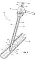
- FIG. 1is a perspective view of a vascular insertion device engaged with an artery, the artery shown in section, according to one embodiment of the present invention.
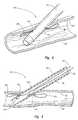
- FIG. 2is a perspective view, partly in section, of the vascular insertion device shown in FIG. 1 engaged with the artery according to one embodiment of the present invention.
- FIG. 3is a perspective view of the vascular insertion device shown in FIG. 1 , illustrating a proximal end of the device according to one embodiment of the present invention.
- FIG. 4is a perspective view of the vascular insertion device shown in FIG. 1 , with locating feet deployed according to one embodiment of the present invention.
- FIG. 5is a cross-sectional view of the vascular insertion device shown in FIG. 4 .
- FIG. 6Ais a perspective view of a locating foot predisposed to bend at a certain point according to one embodiment of the present invention.
- FIG. 6Bis a perspective view of the locating foot of FIG. 6A after it has been bent according to one embodiment of the present invention.
- vascular proceduresare conducted throughout the world and require access to an artery through a puncture.
- the arteryis a femoral artery.
- the present inventiondescribes methods and apparatus for locating a vascular puncture relative to a vascular access device.
- the methods and apparatusindicate location by tactile feedback to an operator. While the vascular instruments shown and described below include particular insertion sheaths, the application of principles described herein to are not limited to the specific devices shown. The principles described herein may be used with any vascular access device. Therefore, while the description below is directed primarily to arterial procedures and certain embodiments of a vascular access device, the methods and apparatus are only limited by the appended claims.
- Lumenrefers to a fluid passageway, for example through a vascular access sheath.
- a “super-elastic” materialrefers to material classes that may be elastically strained at least 6%, some of which can elastically strain up to at least 8-10%.
- Extrude or “extrusion”means the act or process of pushing or thrusting out, and does not necessarily mean that the object being extruded (an “extrudable” object) is changing in cross-sectional shape.
- a vascular insertion apparatusfor example an insertion sheath 100
- the insertion sheath 100is shown partially inserted into a blood vessel, which, according to the embodiment of FIG. 1 , is an artery 102 .
- the insertion sheath 100extends through a puncture 104 in the artery 102 .
- the insertion sheath 100provides access into the artery 102 to any number of vascular instruments and puncture closure devices.
- the insertion sheath 100comprises a tubular member, for example a flexible tubular member 106 .
- the flexible tubular member 106includes a first or distal end 108 , a second or proximal end 110 , and a sidewall 109 .
- the flexible tubular member 106defines a first internal lumen or central inner bore 112 receptive of vascular instruments and closure devices.
- the flexible tubular member 106has a major diameter indicated by D in FIG. 1 , and may be on the order of 0.1 inches.
- the insertion sheath 100includes at least one side port disposed in the sidewall 109 of the flexible tubular member 106 . As shown in FIG.
- the flexible tubular member 106includes a first side port 114 and a second side port 116 that facilitate locating the insertion sheath 100 relative to the puncture 104 .
- the advantages of the first and second side port 114 , 116 for locating the puncture 104are discussed in more detail below.
- the first extrudable memberis disposed in the first lumen 112 .
- the first extrudable memberis a first super elastic ribbon 118 according to FIG. 2 .
- the super elastic ribbon 118may comprise nitinol or other super elastic materials.
- the first super elastic ribbon 118is affixed at a distal end 120 to the first end 108 of the flexible tubular member 106 .
- the distal end 120 of the first super elastic ribbon 118may be affixed to the flexible tubular member 106 by adhesive, welding, or any other affixing method.
- the distal end 120 of the first super elastic ribbon 118is affixed to an inner surface of the flexible tubular member 106 distal of and adjacent to the first side port 114 .
- the first super elastic ribbon 118is preferably azimuthally aligned with the first side port 114 . Therefore, the first super elastic ribbon 118 extends across the first side port 114 .
- the insertion sheath 100may also comprise a second extrudable member such as a second super elastic ribbon 122 .
- the second super elastic ribbon 122may also comprise nitinol.
- the second super elastic ribbon 122is affixed at a distal end 124 to the flexible tubular member 106 in a manner similar or identical to the attachment between the first super elastic ribbon 118 and the flexible tubular member 106 .
- the distal end 124 of the second super elastic ribbon 122is affixed to the flexible tubular member 106 distal of the second side port 116 .
- the second super elastic ribbon 122is preferably azimuthally aligned with the second side port 116 . Therefore, the second super elastic ribbon 122 extends across the second side port 116 .
- the first and second super elastic ribbons 118 , 122extend proximally to free ends that are discussed below with reference to FIG. 3 .
- the first and second side ports 114 , 116are preferably spaced from one another azimuthally.
- the first and second side ports 114 , 116may be spaced azimuthally from one another by approximately 100-300 radial degrees, more preferably by approximately 160-200 radial degrees, and most preferably by approximately 180 degrees such that the first and second side ports 114 , 116 are arranged opposite of one another.
- the first and second side ports 114 , 116are preferably spaced from one another axially. For example, as shown in FIG.
- the first and second side ports 114 , 116lie in a plane 126 at an acute angle ⁇ from a plane 128 normal to the flexible tubular member 106 .
- the acute angle ⁇is preferably within twenty percent or substantially equal to an angle ⁇ at which the insertion sheath 100 is typically inserted relative to the artery 102 .
- the first and second super elastic ribbons 118 , 122each extend proximally to first and second free ends 128 , 130 , respectively.
- the first free end 128may be attached to a first tab 132 and the second free end 130 may be attached to a similar or identical second tab 134 .
- the first and second tabs 132 , 134are accessible to an operator, allowing the operator to apply pressure to the first and second super elastic ribbons 118 , 122 and place the super elastic ribbons in compression. Accordingly, with the insertion sheath 100 placed inside the artery 102 as shown in FIG.
- an operatormay apply pressure to the first and second tabs 132 , 134 to buckle and extrude the first and second super elastic ribbons 118 , 122 through the first and second associated side ports 114 , 116 as shown in FIG. 4 .
- the first and second super elastic ribbons 118 , 122( FIG. 3 ) therefore may act as columns, which will buckle when a critical load is reached.
- first and second super elastic ribbons 118 , 122buckle and extrude through the first and second side ports 114 , 116 , they form first and second feet or petals 136 , 138 , respectively, as shown in FIGS. 4-5 .
- the first and second feet 136 , 138preferably extend substantially parallel to an inner wall 140 of the artery 102 because the first and second ports 114 , 116 are offset axially.
- the first and second feet 136 , 138act as stops and provide tactile feedback to the operator as the insertion sheath 100 is retracted, which results in contact between the first and second feet 136 , 138 and the inner wall 140 .
- the location of the insertion sheath 100 relative to the puncture 104may be accurately determined by the operator when the operator feels the first and/or second feet 136 , 138 contact the inner wall 140 .
- Various vascular instruments or puncture closure devicesmay then be properly introduced through the insertion sheath 100 .
- the first and second feet 136 , 138may be retracted back within the insertion sheath.
- the first and second feet 136 , 138are retracted by pulling on the tabs 132 , 134 ( FIG. 3 ) or otherwise placing the first and second super elastic ribbons 118 , 122 in tension.
- the first and second super elastic ribbons 118 , 122are predisposed to buckle at the first and second side ports 114 , 116 , respectively. Therefore, as shown in FIGS. 6A-6B , the first super elastic ribbon 118 may be weakened at a point adjacent to the first side port 114 ( FIG. 1 ).
- FIGS. 6A-6Billustrate only the first super elastic ribbon 118 , but the second super elastic ribbon 122 ( FIG. 2 ) may be similarly weakened (although in an opposite direction or mirror image).
- the super elastic ribbon 118may include a pre-bend, notch 140 or other controlled weakening mechanism adjacent to the first side port 114 .
- FIG. 6Billustrates the forces on the super elastic ribbon 118 as it is placed in compression and extrudes through the first side port 114 ( FIG. 5 ).
- a major dimension M J of the super elastic ribbon 118is of the same order of magnitude as the major diameter D ( FIG. 1 ) of the flexible tubular member 106 ( FIG. 1 ).
- a minor dimension M N of the super elastic ribbon 118may be an order of magnitude smaller than the major diameter D ( FIG. 1 ) of the flexible tubular member 106 ( FIG. 1 ).
- the first super elastic ribbonmay comprise other dimensions as well.
- the second super elastic ribbon 122( FIG. 5 ) preferably has similar or identical dimensions to the first super elastic ribbon 118 .
Landscapes
- Health & Medical Sciences (AREA)
- Surgery (AREA)
- Life Sciences & Earth Sciences (AREA)
- Medical Informatics (AREA)
- Nuclear Medicine, Radiotherapy & Molecular Imaging (AREA)
- Engineering & Computer Science (AREA)
- Biomedical Technology (AREA)
- Heart & Thoracic Surgery (AREA)
- Cardiology (AREA)
- Molecular Biology (AREA)
- Animal Behavior & Ethology (AREA)
- General Health & Medical Sciences (AREA)
- Public Health (AREA)
- Veterinary Medicine (AREA)
- Surgical Instruments (AREA)
- Media Introduction/Drainage Providing Device (AREA)
Abstract
Description
Claims (33)
Priority Applications (6)
| Application Number | Priority Date | Filing Date | Title |
|---|---|---|---|
| US11/131,120US8273094B2 (en) | 2005-05-17 | 2005-05-17 | Puncture locating device |
| CA2608521ACA2608521C (en) | 2005-05-17 | 2006-04-28 | Puncture locating device |
| EP06751939.7AEP1893098B1 (en) | 2005-05-17 | 2006-04-28 | Puncture locating device |
| PCT/US2006/016499WO2006124251A2 (en) | 2005-05-17 | 2006-04-28 | Puncture locating device |
| AU2006247986AAU2006247986B2 (en) | 2005-05-17 | 2006-04-28 | Puncture locating device |
| JP2008512314AJP2008545459A (en) | 2005-05-17 | 2006-04-28 | Puncture part position finding device |
Applications Claiming Priority (1)
| Application Number | Priority Date | Filing Date | Title |
|---|---|---|---|
| US11/131,120US8273094B2 (en) | 2005-05-17 | 2005-05-17 | Puncture locating device |
Publications (2)
| Publication Number | Publication Date |
|---|---|
| US20060264978A1 US20060264978A1 (en) | 2006-11-23 |
| US8273094B2true US8273094B2 (en) | 2012-09-25 |
Family
ID=37431769
Family Applications (1)
| Application Number | Title | Priority Date | Filing Date |
|---|---|---|---|
| US11/131,120Expired - Fee RelatedUS8273094B2 (en) | 2005-05-17 | 2005-05-17 | Puncture locating device |
Country Status (6)
| Country | Link |
|---|---|
| US (1) | US8273094B2 (en) |
| EP (1) | EP1893098B1 (en) |
| JP (1) | JP2008545459A (en) |
| AU (1) | AU2006247986B2 (en) |
| CA (1) | CA2608521C (en) |
| WO (1) | WO2006124251A2 (en) |
Cited By (11)
| Publication number | Priority date | Publication date | Assignee | Title |
|---|---|---|---|---|
| US20120083829A1 (en)* | 2010-02-26 | 2012-04-05 | ProMed, Inc. | System and method for vessel access closure |
| US9554785B2 (en) | 2012-12-21 | 2017-01-31 | Essential Medical, Inc. | Vascular locating systems and methods of use |
| US10154835B2 (en) | 2013-05-09 | 2018-12-18 | Essential Medical, Inc. | Vascular closure device with conforming plug member |
| US10383611B2 (en) | 2011-10-25 | 2019-08-20 | Essential Medical, Inc. | Instrument and methods for surgically closing percutaneous punctures |
| US11350919B2 (en) | 2019-02-19 | 2022-06-07 | Teleflex Life Sciences Limited | Puncture locating system with blood pulsation indicator |
| US11364024B2 (en) | 2013-12-23 | 2022-06-21 | Teleflex Life Sciences Limited | Vascular closure device |
| US11419592B2 (en) | 2013-03-15 | 2022-08-23 | Teleflex Life Sciences Limited | Vascular closure devices and methods of use |
| US11576663B2 (en) | 2015-06-26 | 2023-02-14 | Teleflex Life Sciences Limited | Vascular closure device with removable guide member |
| US12285160B2 (en) | 2012-07-19 | 2025-04-29 | Teleflex Life Sciences Llc | Multi-lumen tamper tube |
| US12383246B2 (en) | 2020-10-12 | 2025-08-12 | Abbott Cardiovascular Systems, Inc. | Vessel closure device with improved safety and tract hemostasis |
| US12390249B2 (en) | 2020-07-31 | 2025-08-19 | Teleflex Life Sciences Llc | Access sheath with valve assembly |
Families Citing this family (11)
| Publication number | Priority date | Publication date | Assignee | Title |
|---|---|---|---|---|
| US9254124B2 (en)* | 2007-02-05 | 2016-02-09 | Boston Scientific Scimed Inc. | Self-orientating suture wound closure device |
| US8333787B2 (en) | 2007-12-31 | 2012-12-18 | St. Jude Medical Puerto Rico Llc | Vascular closure device having a flowable sealing material |
| US9456816B2 (en) | 2007-09-12 | 2016-10-04 | Transluminal Technologies, Llc | Closure device, deployment apparatus, and method of deploying a closure device |
| JP5426553B2 (en) | 2007-09-12 | 2014-02-26 | トランスルミナル テクノロジーズ リミテッド ライアビリティー カンパニー | Closure device, placement device, and method of placing a closure device |
| US8876861B2 (en) | 2007-09-12 | 2014-11-04 | Transluminal Technologies, Inc. | Closure device, deployment apparatus, and method of deploying a closure device |
| EP2533698B1 (en) | 2010-02-11 | 2018-03-28 | Boston Scientific Scimed, Inc. | Automatic vascular closure deployment devices |
| AU2011326525B2 (en) | 2010-11-09 | 2015-06-18 | Transluminal Technologies, Llc | Specially designed magnesium-aluminum alloys and medical uses thereof in a hemodynamic environment |
| US8758402B2 (en) | 2010-12-17 | 2014-06-24 | Boston Scientific Scimed, Inc. | Tissue puncture closure device |
| US20130035701A1 (en)* | 2011-08-04 | 2013-02-07 | Suture Ease, LLC | Dual insufflation and wound closure devices ans methods |
| US20140288640A1 (en)* | 2013-03-15 | 2014-09-25 | ProMed, Inc. | Systems and methods for improved vessel access closure |
| EP3007631A4 (en)* | 2013-06-11 | 2016-11-16 | Promed Inc | Improved vessel access closure |
Citations (31)
| Publication number | Priority date | Publication date | Assignee | Title |
|---|---|---|---|---|
| US4317445A (en) | 1980-03-31 | 1982-03-02 | Baxter Travenol Laboratories, Inc. | Catheter insertion unit with separate flashback indication for the cannula |
| US5061274A (en) | 1989-12-04 | 1991-10-29 | Kensey Nash Corporation | Plug device for sealing openings and method of use |
| US5222974A (en) | 1991-11-08 | 1993-06-29 | Kensey Nash Corporation | Hemostatic puncture closure system and method of use |
| US5282827A (en) | 1991-11-08 | 1994-02-01 | Kensey Nash Corporation | Hemostatic puncture closure system and method of use |
| US5304184A (en) | 1992-10-19 | 1994-04-19 | Indiana University Foundation | Apparatus and method for positive closure of an internal tissue membrane opening |
| US5306254A (en) | 1992-10-01 | 1994-04-26 | Kensey Nash Corporation | Vessel position locating device and method of use |
| US5403329A (en) | 1992-09-23 | 1995-04-04 | United States Surgical Corporation | Instrument for closing trocar puncture wounds |
| US5405354A (en) | 1993-08-06 | 1995-04-11 | Vance Products Inc. | Suture driver |
| US5411520A (en) | 1991-11-08 | 1995-05-02 | Kensey Nash Corporation | Hemostatic vessel puncture closure system utilizing a plug located within the puncture tract spaced from the vessel, and method of use |
| US5431639A (en)* | 1993-08-12 | 1995-07-11 | Boston Scientific Corporation | Treating wounds caused by medical procedures |
| US5486195A (en) | 1993-07-26 | 1996-01-23 | Myers; Gene | Method and apparatus for arteriotomy closure |
| US5496332A (en) | 1994-10-20 | 1996-03-05 | Cordis Corporation | Wound closure apparatus and method for its use |
| US5613974A (en) | 1992-12-10 | 1997-03-25 | Perclose, Inc. | Apparatus and method for vascular closure |
| US5662681A (en) | 1996-04-23 | 1997-09-02 | Kensey Nash Corporation | Self locking closure for sealing percutaneous punctures |
| US5676689A (en) | 1991-11-08 | 1997-10-14 | Kensey Nash Corporation | Hemostatic puncture closure system including vessel location device and method of use |
| US5725551A (en) | 1993-07-26 | 1998-03-10 | Myers; Gene | Method and apparatus for arteriotomy closure |
| US5728132A (en) | 1996-04-08 | 1998-03-17 | Tricardia, L.L.C. | Self-sealing vascular access device |
| US5755727A (en) | 1995-06-02 | 1998-05-26 | Cardiologics L.L.C. | Method device for locating and sealing a blood vessel |
| US5855559A (en) | 1997-02-14 | 1999-01-05 | Tricardia, Inc. | Hemostatic agent delivery device having built-in pressure sensor |
| US5868778A (en) | 1995-10-27 | 1999-02-09 | Vascular Solutions, Inc. | Vascular sealing apparatus and method |
| US6017359A (en) | 1993-05-25 | 2000-01-25 | Vascular Solutions, Inc. | Vascular sealing apparatus |
| US6042601A (en) | 1998-03-18 | 2000-03-28 | United States Surgical Corporation | Apparatus for vascular hole closure |
| US6048358A (en) | 1998-07-13 | 2000-04-11 | Barak; Shlomo | Method and apparatus for hemostasis following arterial catheterization |
| US6048357A (en) | 1998-07-09 | 2000-04-11 | X-Site, L.L.C. | Anchoring device and method for sealing punctures in vessels |
| US6110184A (en) | 1999-08-04 | 2000-08-29 | Weadock; Kevin S. | Introducer with vascular sealing mechanism |
| US6136010A (en) | 1999-03-04 | 2000-10-24 | Perclose, Inc. | Articulating suturing device and method |
| US6193670B1 (en) | 1997-02-14 | 2001-02-27 | Tricardia, Llc | Hemostatic agent delivery device having built-in pressure sensor |
| US6231561B1 (en) | 1999-09-20 | 2001-05-15 | Appriva Medical, Inc. | Method and apparatus for closing a body lumen |
| US6533762B2 (en) | 2000-09-01 | 2003-03-18 | Angiolink Corporation | Advanced wound site management systems and methods |
| US6682489B2 (en) | 2001-01-12 | 2004-01-27 | Radi Medical Systems Ab | Technique to confirm correct positioning of arterial wall sealing device |
| US20040225301A1 (en) | 2003-05-05 | 2004-11-11 | St. Jude Medical, Daig Division, Inc. | Loop closure apparatus and method |
- 2005
- 2005-05-17USUS11/131,120patent/US8273094B2/ennot_activeExpired - Fee Related
- 2006
- 2006-04-28EPEP06751939.7Apatent/EP1893098B1/ennot_activeNot-in-force
- 2006-04-28CACA2608521Apatent/CA2608521C/ennot_activeExpired - Fee Related
- 2006-04-28AUAU2006247986Apatent/AU2006247986B2/ennot_activeExpired - Fee Related
- 2006-04-28WOPCT/US2006/016499patent/WO2006124251A2/enactiveApplication Filing
- 2006-04-28JPJP2008512314Apatent/JP2008545459A/ennot_activeWithdrawn
Patent Citations (32)
| Publication number | Priority date | Publication date | Assignee | Title |
|---|---|---|---|---|
| US4317445A (en) | 1980-03-31 | 1982-03-02 | Baxter Travenol Laboratories, Inc. | Catheter insertion unit with separate flashback indication for the cannula |
| US5061274A (en) | 1989-12-04 | 1991-10-29 | Kensey Nash Corporation | Plug device for sealing openings and method of use |
| US5222974A (en) | 1991-11-08 | 1993-06-29 | Kensey Nash Corporation | Hemostatic puncture closure system and method of use |
| US5282827A (en) | 1991-11-08 | 1994-02-01 | Kensey Nash Corporation | Hemostatic puncture closure system and method of use |
| US5411520A (en) | 1991-11-08 | 1995-05-02 | Kensey Nash Corporation | Hemostatic vessel puncture closure system utilizing a plug located within the puncture tract spaced from the vessel, and method of use |
| US5441517A (en) | 1991-11-08 | 1995-08-15 | Kensey Nash Corporation | Hemostatic puncture closure system and method of use |
| US5676689A (en) | 1991-11-08 | 1997-10-14 | Kensey Nash Corporation | Hemostatic puncture closure system including vessel location device and method of use |
| US5403329A (en) | 1992-09-23 | 1995-04-04 | United States Surgical Corporation | Instrument for closing trocar puncture wounds |
| US5306254A (en) | 1992-10-01 | 1994-04-26 | Kensey Nash Corporation | Vessel position locating device and method of use |
| US5304184A (en) | 1992-10-19 | 1994-04-19 | Indiana University Foundation | Apparatus and method for positive closure of an internal tissue membrane opening |
| US5613974A (en) | 1992-12-10 | 1997-03-25 | Perclose, Inc. | Apparatus and method for vascular closure |
| US6017359A (en) | 1993-05-25 | 2000-01-25 | Vascular Solutions, Inc. | Vascular sealing apparatus |
| US5725551A (en) | 1993-07-26 | 1998-03-10 | Myers; Gene | Method and apparatus for arteriotomy closure |
| US5486195A (en) | 1993-07-26 | 1996-01-23 | Myers; Gene | Method and apparatus for arteriotomy closure |
| US5405354A (en) | 1993-08-06 | 1995-04-11 | Vance Products Inc. | Suture driver |
| US5431639A (en)* | 1993-08-12 | 1995-07-11 | Boston Scientific Corporation | Treating wounds caused by medical procedures |
| US5496332A (en) | 1994-10-20 | 1996-03-05 | Cordis Corporation | Wound closure apparatus and method for its use |
| US5755727A (en) | 1995-06-02 | 1998-05-26 | Cardiologics L.L.C. | Method device for locating and sealing a blood vessel |
| US5868778A (en) | 1995-10-27 | 1999-02-09 | Vascular Solutions, Inc. | Vascular sealing apparatus and method |
| US5728132A (en) | 1996-04-08 | 1998-03-17 | Tricardia, L.L.C. | Self-sealing vascular access device |
| US5662681A (en) | 1996-04-23 | 1997-09-02 | Kensey Nash Corporation | Self locking closure for sealing percutaneous punctures |
| US5855559A (en) | 1997-02-14 | 1999-01-05 | Tricardia, Inc. | Hemostatic agent delivery device having built-in pressure sensor |
| US6193670B1 (en) | 1997-02-14 | 2001-02-27 | Tricardia, Llc | Hemostatic agent delivery device having built-in pressure sensor |
| US6042601A (en) | 1998-03-18 | 2000-03-28 | United States Surgical Corporation | Apparatus for vascular hole closure |
| US6048357A (en) | 1998-07-09 | 2000-04-11 | X-Site, L.L.C. | Anchoring device and method for sealing punctures in vessels |
| US6048358A (en) | 1998-07-13 | 2000-04-11 | Barak; Shlomo | Method and apparatus for hemostasis following arterial catheterization |
| US6136010A (en) | 1999-03-04 | 2000-10-24 | Perclose, Inc. | Articulating suturing device and method |
| US6110184A (en) | 1999-08-04 | 2000-08-29 | Weadock; Kevin S. | Introducer with vascular sealing mechanism |
| US6231561B1 (en) | 1999-09-20 | 2001-05-15 | Appriva Medical, Inc. | Method and apparatus for closing a body lumen |
| US6533762B2 (en) | 2000-09-01 | 2003-03-18 | Angiolink Corporation | Advanced wound site management systems and methods |
| US6682489B2 (en) | 2001-01-12 | 2004-01-27 | Radi Medical Systems Ab | Technique to confirm correct positioning of arterial wall sealing device |
| US20040225301A1 (en) | 2003-05-05 | 2004-11-11 | St. Jude Medical, Daig Division, Inc. | Loop closure apparatus and method |
Cited By (19)
| Publication number | Priority date | Publication date | Assignee | Title |
|---|---|---|---|---|
| US9439635B2 (en)* | 2010-02-26 | 2016-09-13 | ProMed, Inc. | Method for vessel access closure |
| US20120083829A1 (en)* | 2010-02-26 | 2012-04-05 | ProMed, Inc. | System and method for vessel access closure |
| US10485524B2 (en) | 2011-10-25 | 2019-11-26 | Essential Medical, Inc. | Instrument and methods for surgically closing percutaneous punctures |
| US11589855B2 (en) | 2011-10-25 | 2023-02-28 | Teleflex Life Sciences Limited | Instrument and methods for surgically closing percutaneous punctures |
| US10383611B2 (en) | 2011-10-25 | 2019-08-20 | Essential Medical, Inc. | Instrument and methods for surgically closing percutaneous punctures |
| US12285160B2 (en) | 2012-07-19 | 2025-04-29 | Teleflex Life Sciences Llc | Multi-lumen tamper tube |
| US10182804B2 (en) | 2012-12-21 | 2019-01-22 | Essential Medical, Inc. | Vascular locating systems and methods of use |
| US10835225B2 (en) | 2012-12-21 | 2020-11-17 | Arrow International, Inc. | Vascular locating systems and methods of use |
| US11759191B2 (en) | 2012-12-21 | 2023-09-19 | Teleflex Life Sciences Limited | Vascular locating systems and methods of use |
| US9554785B2 (en) | 2012-12-21 | 2017-01-31 | Essential Medical, Inc. | Vascular locating systems and methods of use |
| US11419592B2 (en) | 2013-03-15 | 2022-08-23 | Teleflex Life Sciences Limited | Vascular closure devices and methods of use |
| US12426865B2 (en) | 2013-03-15 | 2025-09-30 | Teleflex Life Sciences Llc | Vascular closure devices and methods of use |
| US10154835B2 (en) | 2013-05-09 | 2018-12-18 | Essential Medical, Inc. | Vascular closure device with conforming plug member |
| US11364024B2 (en) | 2013-12-23 | 2022-06-21 | Teleflex Life Sciences Limited | Vascular closure device |
| US11779320B2 (en) | 2013-12-23 | 2023-10-10 | Teleflex Life Sciences Limited | Vascular closure device |
| US11576663B2 (en) | 2015-06-26 | 2023-02-14 | Teleflex Life Sciences Limited | Vascular closure device with removable guide member |
| US11350919B2 (en) | 2019-02-19 | 2022-06-07 | Teleflex Life Sciences Limited | Puncture locating system with blood pulsation indicator |
| US12390249B2 (en) | 2020-07-31 | 2025-08-19 | Teleflex Life Sciences Llc | Access sheath with valve assembly |
| US12383246B2 (en) | 2020-10-12 | 2025-08-12 | Abbott Cardiovascular Systems, Inc. | Vessel closure device with improved safety and tract hemostasis |
Also Published As
| Publication number | Publication date |
|---|---|
| CA2608521A1 (en) | 2006-11-23 |
| EP1893098A4 (en) | 2011-09-14 |
| WO2006124251A2 (en) | 2006-11-23 |
| EP1893098A2 (en) | 2008-03-05 |
| AU2006247986A1 (en) | 2006-11-23 |
| WO2006124251A3 (en) | 2009-04-23 |
| JP2008545459A (en) | 2008-12-18 |
| AU2006247986B2 (en) | 2012-07-12 |
| CA2608521C (en) | 2013-10-01 |
| US20060264978A1 (en) | 2006-11-23 |
| EP1893098B1 (en) | 2014-01-15 |
Similar Documents
| Publication | Publication Date | Title |
|---|---|---|
| CA2608521C (en) | Puncture locating device | |
| EP1371333B1 (en) | Closure device | |
| US5320639A (en) | Vascular plug delivery system | |
| CA2152061C (en) | Surgical depth measuring instrument and method | |
| US6494848B1 (en) | Measuring device for use with a hemostatic puncture closure device | |
| JP5248659B2 (en) | Dilator device for ventricular puncture | |
| US20130144331A1 (en) | Introducer sheath | |
| CA2341228C (en) | Sizing catheter for measuring septal defects | |
| US20050096696A1 (en) | Arteriotomy closure device with anti-roll anchor | |
| US20050096697A1 (en) | Vascular insertion sheath with stiffened tip | |
| JP2006524550A (en) | Apparatus and method for installing a closure device | |
| US20110077598A1 (en) | Vascular access to closure sheath and methods | |
| CN106943183B (en) | Minimally invasive flexible puncture tube and minimally invasive channel puncture assembly | |
| US20230087959A1 (en) | Depth gauge system | |
| US20220361861A1 (en) | Concentric core puncture locating system | |
| EP1442708B1 (en) | Introducer sheath | |
| AU779675B2 (en) | Measuring device for use with a hemostatic puncture closure device | |
| DE112022005969T5 (en) | Probe for determining the size of an opening in a blood vessel |
Legal Events
| Date | Code | Title | Description |
|---|---|---|---|
| AS | Assignment | Owner name:ST. JUDE MEDICAL PUERTO RICO B.V., NETHERLANDS Free format text:ASSIGNMENT OF ASSIGNORS INTEREST;ASSIGNORS:BELHE, KEDAR R.;ROOP, JOHN AVI;SIGNING DATES FROM 20050720 TO 20050721;REEL/FRAME:016864/0029 Owner name:ST. JUDE MEDICAL PUERTO RICO B.V., NETHERLANDS Free format text:ASSIGNMENT OF ASSIGNORS INTEREST;ASSIGNORS:BELHE, KEDAR R.;ROOP, JOHN AVI;REEL/FRAME:016864/0029;SIGNING DATES FROM 20050720 TO 20050721 | |
| AS | Assignment | Owner name:ST. JUDE MEDICAL PUERTO RICO LLC, PUERTO RICO Free format text:ACQUISITION;ASSIGNOR:ST. JUDE MEDICAL PUERTO RICO B.V.;REEL/FRAME:021998/0591 Effective date:20071228 Owner name:ST. JUDE MEDICAL PUERTO RICO LLC,PUERTO RICO Free format text:ACQUISITION;ASSIGNOR:ST. JUDE MEDICAL PUERTO RICO B.V.;REEL/FRAME:021998/0591 Effective date:20071228 | |
| STCF | Information on status: patent grant | Free format text:PATENTED CASE | |
| FPAY | Fee payment | Year of fee payment:4 | |
| MAFP | Maintenance fee payment | Free format text:PAYMENT OF MAINTENANCE FEE, 8TH YEAR, LARGE ENTITY (ORIGINAL EVENT CODE: M1552); ENTITY STATUS OF PATENT OWNER: LARGE ENTITY Year of fee payment:8 | |
| FEPP | Fee payment procedure | Free format text:MAINTENANCE FEE REMINDER MAILED (ORIGINAL EVENT CODE: REM.); ENTITY STATUS OF PATENT OWNER: LARGE ENTITY | |
| LAPS | Lapse for failure to pay maintenance fees | Free format text:PATENT EXPIRED FOR FAILURE TO PAY MAINTENANCE FEES (ORIGINAL EVENT CODE: EXP.); ENTITY STATUS OF PATENT OWNER: LARGE ENTITY | |
| STCH | Information on status: patent discontinuation | Free format text:PATENT EXPIRED DUE TO NONPAYMENT OF MAINTENANCE FEES UNDER 37 CFR 1.362 | |
| FP | Lapsed due to failure to pay maintenance fee | Effective date:20240925 |