US8273015B2 - Methods for imaging the anatomy with an anatomically secured scanner assembly - Google Patents
Methods for imaging the anatomy with an anatomically secured scanner assemblyDownload PDFInfo
- Publication number
- US8273015B2 US8273015B2US11/749,188US74918807AUS8273015B2US 8273015 B2US8273015 B2US 8273015B2US 74918807 AUS74918807 AUS 74918807AUS 8273015 B2US8273015 B2US 8273015B2
- Authority
- US
- United States
- Prior art keywords
- scanner assembly
- anatomy
- scanner
- assembly
- collector
- Prior art date
- Legal status (The legal status is an assumption and is not a legal conclusion. Google has not performed a legal analysis and makes no representation as to the accuracy of the status listed.)
- Expired - Fee Related, expires
Links
- 210000003484anatomyAnatomy0.000titleclaimsabstractdescription76
- 238000003384imaging methodMethods0.000titleclaimsdescription28
- 238000000034methodMethods0.000titleabstractdescription21
- 230000005855radiationEffects0.000claimsabstractdescription36
- 239000000835fiberSubstances0.000claimsdescription32
- 238000003780insertionMethods0.000claimsdescription20
- 230000037431insertionEffects0.000claimsdescription20
- 239000000463materialSubstances0.000description13
- 230000000149penetrating effectEffects0.000description7
- 230000001225therapeutic effectEffects0.000description7
- 210000001519tissueAnatomy0.000description6
- 230000007246mechanismEffects0.000description5
- 238000007493shaping processMethods0.000description5
- 206010019909HerniaDiseases0.000description4
- 210000001015abdomenAnatomy0.000description4
- 238000010586diagramMethods0.000description4
- 238000002560therapeutic procedureMethods0.000description4
- 238000011282treatmentMethods0.000description4
- 230000008901benefitEffects0.000description3
- 239000003550markerSubstances0.000description3
- 239000013307optical fiberSubstances0.000description3
- 239000000853adhesiveSubstances0.000description2
- 230000001070adhesive effectEffects0.000description2
- 210000000988bone and boneAnatomy0.000description2
- 238000003745diagnosisMethods0.000description2
- 238000004519manufacturing processMethods0.000description2
- 239000002184metalSubstances0.000description2
- 229910052751metalInorganic materials0.000description2
- 238000012986modificationMethods0.000description2
- 230000004048modificationEffects0.000description2
- HLXZNVUGXRDIFK-UHFFFAOYSA-Nnickel titaniumChemical compound[Ti].[Ti].[Ti].[Ti].[Ti].[Ti].[Ti].[Ti].[Ti].[Ti].[Ti].[Ni].[Ni].[Ni].[Ni].[Ni].[Ni].[Ni].[Ni].[Ni].[Ni].[Ni].[Ni].[Ni].[Ni]HLXZNVUGXRDIFK-UHFFFAOYSA-N0.000description2
- 229910001000nickel titaniumInorganic materials0.000description2
- 230000003287optical effectEffects0.000description2
- 210000000056organAnatomy0.000description2
- 239000011800void materialSubstances0.000description2
- 210000000436anusAnatomy0.000description1
- 238000005452bendingMethods0.000description1
- 230000005540biological transmissionEffects0.000description1
- 210000004204blood vesselAnatomy0.000description1
- 230000008859changeEffects0.000description1
- 238000006243chemical reactionMethods0.000description1
- 210000001072colonAnatomy0.000description1
- 238000010276constructionMethods0.000description1
- 238000012937correctionMethods0.000description1
- 238000001514detection methodMethods0.000description1
- 238000002405diagnostic procedureMethods0.000description1
- 201000010099diseaseDiseases0.000description1
- 208000037265diseases, disorders, signs and symptomsDiseases0.000description1
- 210000003238esophagusAnatomy0.000description1
- 239000004744fabricSubstances0.000description1
- 239000012530fluidSubstances0.000description1
- 239000007850fluorescent dyeSubstances0.000description1
- 230000006870functionEffects0.000description1
- 230000014509gene expressionEffects0.000description1
- PCHJSUWPFVWCPO-UHFFFAOYSA-NgoldChemical compound[Au]PCHJSUWPFVWCPO-UHFFFAOYSA-N0.000description1
- 239000010931goldSubstances0.000description1
- 229910052737goldInorganic materials0.000description1
- 238000001727in vivoMethods0.000description1
- 210000000936intestineAnatomy0.000description1
- 238000013507mappingMethods0.000description1
- 239000011159matrix materialSubstances0.000description1
- 238000012544monitoring processMethods0.000description1
- 229920000642polymerPolymers0.000description1
- 239000002861polymer materialSubstances0.000description1
- 229920001296polysiloxanePolymers0.000description1
- 238000007639printingMethods0.000description1
- 238000012545processingMethods0.000description1
- 210000002307prostateAnatomy0.000description1
- 230000000717retained effectEffects0.000description1
- 230000035945sensitivityEffects0.000description1
- 210000004872soft tissueAnatomy0.000description1
- 239000007787solidSubstances0.000description1
- 210000002784stomachAnatomy0.000description1
- 239000000126substanceSubstances0.000description1
- 238000004381surface treatmentMethods0.000description1
- 239000004753textileSubstances0.000description1
- 210000000115thoracic cavityAnatomy0.000description1
- 210000001113umbilicusAnatomy0.000description1
- 210000000626ureterAnatomy0.000description1
- 210000003708urethraAnatomy0.000description1
- 210000004291uterusAnatomy0.000description1
- 210000001835visceraAnatomy0.000description1
Images


Classifications
- A—HUMAN NECESSITIES
- A61—MEDICAL OR VETERINARY SCIENCE; HYGIENE
- A61B—DIAGNOSIS; SURGERY; IDENTIFICATION
- A61B1/00—Instruments for performing medical examinations of the interior of cavities or tubes of the body by visual or photographical inspection, e.g. endoscopes; Illuminating arrangements therefor
- A61B1/04—Instruments for performing medical examinations of the interior of cavities or tubes of the body by visual or photographical inspection, e.g. endoscopes; Illuminating arrangements therefor combined with photographic or television appliances
- A61B1/041—Capsule endoscopes for imaging
- A—HUMAN NECESSITIES
- A61—MEDICAL OR VETERINARY SCIENCE; HYGIENE
- A61B—DIAGNOSIS; SURGERY; IDENTIFICATION
- A61B1/00—Instruments for performing medical examinations of the interior of cavities or tubes of the body by visual or photographical inspection, e.g. endoscopes; Illuminating arrangements therefor
- A61B1/00064—Constructional details of the endoscope body
- A61B1/00071—Insertion part of the endoscope body
- A61B1/0008—Insertion part of the endoscope body characterised by distal tip features
- A61B1/00096—Optical elements
- A—HUMAN NECESSITIES
- A61—MEDICAL OR VETERINARY SCIENCE; HYGIENE
- A61B—DIAGNOSIS; SURGERY; IDENTIFICATION
- A61B1/00—Instruments for performing medical examinations of the interior of cavities or tubes of the body by visual or photographical inspection, e.g. endoscopes; Illuminating arrangements therefor
- A61B1/00147—Holding or positioning arrangements
- A61B1/00148—Holding or positioning arrangements using anchoring means
- A—HUMAN NECESSITIES
- A61—MEDICAL OR VETERINARY SCIENCE; HYGIENE
- A61B—DIAGNOSIS; SURGERY; IDENTIFICATION
- A61B1/00—Instruments for performing medical examinations of the interior of cavities or tubes of the body by visual or photographical inspection, e.g. endoscopes; Illuminating arrangements therefor
- A61B1/00147—Holding or positioning arrangements
- A61B1/00158—Holding or positioning arrangements using magnetic field
- A—HUMAN NECESSITIES
- A61—MEDICAL OR VETERINARY SCIENCE; HYGIENE
- A61B—DIAGNOSIS; SURGERY; IDENTIFICATION
- A61B1/00—Instruments for performing medical examinations of the interior of cavities or tubes of the body by visual or photographical inspection, e.g. endoscopes; Illuminating arrangements therefor
- A61B1/00163—Optical arrangements
- A61B1/00172—Optical arrangements with means for scanning
- A—HUMAN NECESSITIES
- A61—MEDICAL OR VETERINARY SCIENCE; HYGIENE
- A61B—DIAGNOSIS; SURGERY; IDENTIFICATION
- A61B1/00—Instruments for performing medical examinations of the interior of cavities or tubes of the body by visual or photographical inspection, e.g. endoscopes; Illuminating arrangements therefor
- A61B1/00163—Optical arrangements
- A61B1/00174—Optical arrangements characterised by the viewing angles
- A61B1/00183—Optical arrangements characterised by the viewing angles for variable viewing angles
- A—HUMAN NECESSITIES
- A61—MEDICAL OR VETERINARY SCIENCE; HYGIENE
- A61B—DIAGNOSIS; SURGERY; IDENTIFICATION
- A61B5/00—Measuring for diagnostic purposes; Identification of persons
- A61B5/68—Arrangements of detecting, measuring or recording means, e.g. sensors, in relation to patient
- A61B5/6846—Arrangements of detecting, measuring or recording means, e.g. sensors, in relation to patient specially adapted to be brought in contact with an internal body part, i.e. invasive
- A61B5/6879—Means for maintaining contact with the body
- A61B5/6882—Anchoring means
- A—HUMAN NECESSITIES
- A61—MEDICAL OR VETERINARY SCIENCE; HYGIENE
- A61B—DIAGNOSIS; SURGERY; IDENTIFICATION
- A61B1/00—Instruments for performing medical examinations of the interior of cavities or tubes of the body by visual or photographical inspection, e.g. endoscopes; Illuminating arrangements therefor
- A61B1/06—Instruments for performing medical examinations of the interior of cavities or tubes of the body by visual or photographical inspection, e.g. endoscopes; Illuminating arrangements therefor with illuminating arrangements
- A61B1/0638—Instruments for performing medical examinations of the interior of cavities or tubes of the body by visual or photographical inspection, e.g. endoscopes; Illuminating arrangements therefor with illuminating arrangements providing two or more wavelengths
- A—HUMAN NECESSITIES
- A61—MEDICAL OR VETERINARY SCIENCE; HYGIENE
- A61B—DIAGNOSIS; SURGERY; IDENTIFICATION
- A61B1/00—Instruments for performing medical examinations of the interior of cavities or tubes of the body by visual or photographical inspection, e.g. endoscopes; Illuminating arrangements therefor
- A61B1/06—Instruments for performing medical examinations of the interior of cavities or tubes of the body by visual or photographical inspection, e.g. endoscopes; Illuminating arrangements therefor with illuminating arrangements
- A61B1/07—Instruments for performing medical examinations of the interior of cavities or tubes of the body by visual or photographical inspection, e.g. endoscopes; Illuminating arrangements therefor with illuminating arrangements using light-conductive means, e.g. optical fibres
- A—HUMAN NECESSITIES
- A61—MEDICAL OR VETERINARY SCIENCE; HYGIENE
- A61B—DIAGNOSIS; SURGERY; IDENTIFICATION
- A61B2562/00—Details of sensors; Constructional details of sensor housings or probes; Accessories for sensors
- A61B2562/02—Details of sensors specially adapted for in-vivo measurements
- A61B2562/028—Microscale sensors, e.g. electromechanical sensors [MEMS]
Definitions
- the present applicationrelates generally to imaging the anatomy with a resonant scanner that has been secured to an anatomical structure.
- U.S. Published application 2005/0020926discloses a scanned beam imager that may be used in applications in which cameras have been used in the past. In particular it can be used in medical devices such as video endoscopes, laparoscopes, etc.
- the scanned beam imager disclosedhas an illuminator that creates a first beam of light and a scanner that deflects the first beam of light across a field-of-view (FOV).
- the scanned beam of lightsequentially illuminates spots in the FOV corresponding to various beam positions. While the beam illuminates the spots, the illuminating light beam is reflected, absorbed, scattered, refracted, or otherwise affected by the object or material in the FOV to produce scattered light energy. A portion of the scattered light energy travels to detectors that receive the light and produce electrical signals corresponding to the amount of light energy received, which is then converted to separate electrical signals.
- the electrical signalspass to a controller that builds up a digital image and transmits it for further processing, decoding, archiving, printing, display, or other treatment or use.
- Such scanned beam imagersare a useful tool for imaging, but may be useful for much more.
- the “imager”is more than just and imager, but is a scanner assembly that may be able to image, diagnose, analyze, treat, or activate a portion of the FOV or a substance within the FOV.
- the scanner assemblymay be made on a smaller scale than typical cameras, deployable or incorporated into a medical instrument, and/or include zoom capabilities, which all make for a less invasive medical procedure. Less invasive medical procedures are easier for a patient to recover from. More specifically, a smaller scanner assembly will reduce the size of the incision or opening necessary to introduce the scanner assembly.
- the deployable scanner assembly itself or a medical instrument with the scanner assembly incorporated within its structurewill reduce the number of instruments that need to be introduced into the body. Zoom capabilities allow the user to enlarge or reduce the image without moving the actual scanner assembly once inside the body.
- the inventionincludes a method for viewing a portion of a patient's anatomy that comprises placing a scanner assembly including an oscillating reflector in the anatomy, securing the scanner assembly to an anatomical structure, scanning the anatomy with the scanner assembly secured to the anatomical structure, collecting radiation returned from the scanned anatomy, and generating a displayable image of the anatomy.
- the inventionincludes a scanner assembly for use with a scanning beam device.
- the scanner assemblycomprises a housing, an oscillating reflector to direct a beam of radiation onto a portion of a patient's anatomy, a cable extending from the housing to link the reflector to a component of a scanning beam device, and a connecting structure to secure the housing to an anatomical structure.
- the inventionin another embodiment, includes a scanner assembly and a collector that converts from a first conformation to facilitate insertion into the anatomy and a second conformation to facilitate imaging the anatomy that comprises a scanner assembly with a plurality of fiber bundles arranged around its periphery, the bundles being longitudinally staggered in the first conformation such that the combination of the bundles and the assembly provides a pointed end for inserting into the anatomy and in the second conformation the plurality of collecting fiber bundles are aligned the scanner assembly to provide an imaging end.
- FIG. 1is a block diagram of an embodiment of a medical device system including a scanner assembly
- FIG. 2is a block diagram of an embodiment of a source assembly including multiple sources for generating imaging, therapeutic and aiming beams;
- FIG. 3is a block diagram illustrating radiation paths
- FIG. 4is an illustration of a bi-sinusoidal scan pattern and a rectangular coordinate pattern plotted together;
- FIG. 5is a perspective view of an embodiment of a scanner assembly
- FIG. 6is a side, section view of the scanner assembly of FIG. 5 along line 6 - 6 ;
- FIG. 7is a perspective view of an embodiment of a collector
- FIG. 8Ais a side view of a scanner assembly including a connecting structure
- FIGS. 8B , 8 Care side views of a scanner assembly including a anchor type connecting structure
- FIG. 9illustrates the scanner assembly of FIG. 8A secured to an anatomical structure
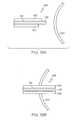
- FIG. 10is a side view of a scanner assembly including an expandable connecting structure that is within an introducer;
- FIG. 11illustrates the scanner assembly of FIG. 10 secured to an anatomical structure
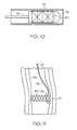
- FIG. 12is a side view of a scanner assembly including an expandable connecting structure having a barb that is within an introducer;
- FIG. 13illustrates the scanner assembly of FIG. 12 secured to an anatomical structure
- FIG. 14is a flow chart of a method for viewing a portion of a patient's internal anatomy
- FIG. 15is a side section view of a body with a scanning module inserted therein;
- FIG. 16is a side section view of a body with an introducer including a scanning module inserted therein;
- FIG. 17is a cross-sectional view of the body including a separate scanner assembly and collector;
- FIGS. 18A and 18Bare cross-sectional views of a body illustrating the separate insertion of a scanner assembly and a collector that after insertion are magnetically coupled;
- FIGS. 19A and 19Bare perspective views of an adjustable combined scanner assembly and collector.
- an embodiment of a scanning beam device 1which may be part of a medical device, includes scanner assembly 2 , collector 3 , radiation source assembly 4 , detector assembly 5 , controller 6 , and user interface 7 .
- the radiation source assembly 4 , detector assembly 5 , controller 6 and user interface 7make up functional element 8 that is known herein as a “console.”
- the radiation source assembly 4as selected by the user via the user interface 7 , and acting through the controller 6 , generates a wavelength of radiation (e.g., in the visible wavelength range and/or otherwise). This radiation is conveyed in a beam to scanner assembly 2 , which causes the beam to be swept across an anatomical surface.
- the extent of this swept areais generally known as the “field of view” (FOV).
- Radiation returned from the scene (e.g., tissue, structures, and organs) within the FOVmay be received by collector 3 and passed to detector assembly 5 .
- the detector assemblyconverts the received radiation to electrical signals that are then processed by the controller to form an image on a display assembly, which in one embodiment may be included in user interface 7 .
- FIG. 2is a block diagram of one implementation of source assembly 4 .
- Source assembly 4includes multiple sources, each capable of generating radiation at a selected wavelength. Five sources are shown here, numbered 11 thru 15 . It should be noted that while five sources are illustrated, there may be more or fewer sources depending, for example, on the end use.
- the outputs of the radiation sources 11 - 15may be brought together in combiner 16 to yield output beam 17 .
- Combiner 16may also include beam-shaping optics such as one or more collimating lenses and/or apertures.
- the sourcesmay be of various types such as, but not limited thereto, light emitting diodes (LEDs), lasers, thermal sources, arc sources, fluorescent sources, gas discharge sources, or others.
- LEDslight emitting diodes
- laserslasers
- thermal sourcesthermal sources
- arc sourcesfluorescent sources
- gas discharge sourcesor others.
- sources 11 , 12 and 13comprise three lasers; a red diode laser, a green diode-pumped solid state (DPSS) laser, and a blue DPSS laser at approximately 635 nm, 532 nm, and 473 nm, respectively.
- Signals 42may be provided by controller 6 ( FIG. 1 ) to one or more of the sources and optionally combiner 16 .
- Signals 42may optionally control wavelength, power, modulation or other beam properties.
- the power of the beammay be modulated by a modulator, as taught in commonly assigned U.S. patent application Ser. No. 11/716,911, titled POWER MODULATION OF A SCANNING BEAM FOR IMAGING, THERAPY, AND/OR DIAGNOSIS, which is hereby incorporated by reference in its entirety.
- the wavelength of radiationmay be selected for imaging, therapy, or aiming.
- an “imaging beam”refers to radiation selected for use in creating an image of a surface or region
- a “therapeutic beam”refers to radiation selected to provide treatment of a condition such as diseased or damaged tissue
- an “aiming beam”refers to radiation selected to accentuate a portion of the FOV.
- an additional sourcemay provide a “diagnostic beam.”
- a “diagnostic beam” as used hereinrefers to radiation selected for analysis or detection of a disease or other medical condition including, for example, to visualize the presence of (or to activate) a diagnostic marker.
- the diagnostic markercould be naturally occurring (e.g., auto or self fluorescence) or introduced as part of the diagnostic procedure (e.g., fluorescent dyes).
- the apparatus to operate such beamsis disclosed in commonly assigned U.S. patent application Ser. No. 11/716,806, titled MEDICAL DEVICE INCLUDING SCANNED BEAM UNIT FOR IMAGING, THERAPY, AND/OR DIAGNOSIS, as well as the operation of treatment mapping or selecting a treatment path. This reference is hereby incorporated by reference in its entirety.
- FIG. 3illustrates the operation of device 1 .
- Reflector 27which is usually included in scanner assembly 2 , receives a beam of radiation 17 from source assembly 4 and directs the beam onto surface 20 , for example, for one or more of imaging, therapy, diagnostic, or aiming purposes. At one point in time, the beam deflected by reflector 27 is in the direction shown as 21 , and impinges upon the surface to illuminate point 23 . Reflector 27 oscillates in at least one axis (two axes in some embodiments), as indicated by the nearby arrowed arc, so that at some other point in time the deflected beam is in the direction indicated as 22 where, it illuminates point 24 .
- Radiationis, in general, reflected, absorbed, scattered, refracted or otherwise affected by the properties of the surface. Radiation may leave the surface in many directions. Collector 3 , however, may only receive that fraction of radiation which is returned from the surface and falls into the area subtended by its aperture. Regions 25 and 26 show the returned radiation that is captured by collector 3 when the beam is illuminating points 23 and 24 respectively. Directions 21 and 22 are not intended to represent any special part of the scan as the beam may be scanned using reflector 27 beyond them, and scans all points between them as well. Furthermore, a simplified two-dimensional view is represented by FIG. 3 , and in general reflector 27 and collector 3 are adapted to illuminate and receive radiation from surfaces occupying space in three dimensions. Radiation returned from the FOV received by collector 3 is passed to detector assembly 5 .
- MEMS scanner reflectoruses a micro-electromechanical (MEMS) scanner reflector to direct the imaging, aiming and therapeutic beams onto the surface.
- MEMS scanner reflectorsare described in, for example, U.S. Pat. No. 6,140,979, entitled SCANNED DISPLAY WITH PINCH, TIMING, AND DISTORTION CORRECTION; U.S. Pat. No. 6,245,590, entitled FREQUENCY TUNABLE RESONANT SCANNER AND METHOD OF MAKING; U.S. Pat. No. 6,285,489, entitled FREQUENCY TUNABLE RESONANT SCANNER WITH AUXILIARY ARMS; U.S. Pat. No.
- reflector 27scans the beam of radiation in a pattern shown as an idealized bi-resonant or bi-sinusoidal scan pattern.
- High-speed MEMS reflectors and other resonant deflectors as described hereinare configured and driven to execute sinusoidal angular deflections in two orthogonal axes, yielding the Lissajous pattern shown in FIG. 4 .
- Most current display devicesare configured to address display data in a Cartesian form, for example as row and column, or a particular pixel along a nearly-horizontal scan line.
- the bi-resonant or Lissajous scan path 30is shown overlaid with the Cartesian or rectilinear grid 31 .
- the intersections between the vertical and horizontal lines of the Cartesian grid 30represent display pixel positions while the Lissajous trace 31 represents the actual path taken by the scanned spot. As the actual scan path does not align perfectly with all the rectilinear pixel positions, these image values may be determined through interpolation. In some embodiments, registration of the Lissajous trace 30 to the Cartesian grid 31 is based on a marker that links a reference point in the scan to a point in the rectilinear matrix.
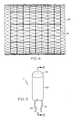
- FIG. 5is an external view of one embodiment of the scanner assembly 2 .
- Scanner assembly 2includes a housing 50 that encloses the reflector 27 and other components.
- a source fiber 51is used to deliver radiation from the source assembly 4 to the scanner assembly 2 .
- Source fiber 51may be a single mode optical fiber.
- one or more fibersmay be used to deliver imaging beams and one or more other fibers may be used to deliver a therapeutic beam (e.g., therapeutic beams having longer wavelengths, e.g., greater than 1700 nm and/or higher power).
- a different type of fibersuch as a holey fiber, may be used to transmit energy from the source assembly 4 .
- the same optical fiber 51is used to deliver both the imaging beams and the therapeutic beams to the reflector, the optical fiber defining a common path for both types of beams.
- Electrical wires 52convey drive signals for the reflector 27 and other signals (position feedback, temperature, etc.) to and from controller 6 ( FIG. 1 ). Wires 52 may also provide control and feedback connections for controlling focus characteristics of the beam shaping optic 56 .
- source fiber 51 , electrical wires 52 and any other fibers or wires connected to scanner assembly 2may be bound together into a cable (shown as 76 in FIG. 8 ).
- the distal end of the scanner assembly 2may be fitted with an optical element 53 which allows the scanned beam to illuminate the FOV.
- This element 53is generally referred to and illustrated as a dome; however, its curvature, contour, and surface treatments may depend on the application and optical properties required.
- dome 53provides a hermetic seal with the housing 50 to protect the internal elements from the environment.
- FIG. 6shows one embodiment for the internal components of scanner assembly 2 .
- Source fiber 51is affixed to the housing 50 by ferrule 54 .
- the end of the source fiber 51may be polished to create a beam 55 of known divergence.
- the beam 55may be shaped by a beam shaping optic or lens 56 to create a beam shape appropriate for transmission through the system.
- shaped beam 57is fed through an aperture in the center of reflector 27 , then reflected off a first reflecting surface 58 .
- First reflecting surface 58may have a beam shaping function. Beam 57 is then directed onto reflector 27 and then out of scanner assembly 2 , the details of which (in the case of an imaging beam) are described in U.S.
- reflector 27Any suitable materials can be used to form reflector 27 .
- the reflective surface of reflector 27may be formed of gold or other suitable material for directing each of the beams including relative high energy therapeutic radiation.
- a multilayer dielectric configurationmay be used in forming reflector 27 .
- scanning beam device 1may include a zoom mechanism.
- the zoom mechanismmay operate by adjusting the scan of the oscillating reflector included in scanner assembly 2 .
- the zoom mechanismadjusts the scan by reducing the frequency of the scan to collect more data within each specified area, e.g., a pixel, of the FOV.
- the zoom mechanismadjusts the scan by reducing the area the scanner sweeps across within the FOV, which allows the collection of more data within the reduced area. In this way, scanner assembly 2 does not need to be physically moved nearer or farther from the FOV to get a larger or smaller image.
- Scanner assembly 2may be about 2 to about 4 millimeters by about 4 to about 10 millimeters, or any other suitable dimension. Scanner assembly 2 may by cylindrical, rectangular, or any other configuration that can be inserted into the body, or made part of an introducer. Scanner assembly 2 may be capable of being deployed within the anatomy. In one embodiment, scanner assembly 2 may enter the anatomy through a natural orifice (i.e. the mouth, nasal passage, anus, urethra, ureter, etc.) for a less invasive procedure.
- a natural orificei.e. the mouth, nasal passage, anus, urethra, ureter, etc.
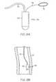
- collector 3may include face 60 , central void 61 , housing 62 , and collecting fibers 63 . Radiation reflected from the FOV impinges on the face 60 of collector 3 , which constitutes the receiving aperture. Face 60 may be made up of the polished ends of a large number of small diameter, multimode collecting fibers 63 which conduct the radiation to detector assembly 5 ( FIGS. 1 and 3 ).
- scanner assembly 2is inserted into central void 61 of housing 62 to form a module 70 that has a cable to connect the module 70 to the console 8 of scanning beam device 1 .
- the cablemay include the bundle of collecting fibers, the source fiber, and any other wiring for controlling scanner assembly 2 and collector 3 .
- the fiber ends making up face 60may be formed in a plane, or into other geometries to control the pattern of receiving sensitivity. They may be coated with diffusing or other materials to improve their angle of acceptance, to provide wavelength conversion, or wavelength selectivity.
- detector assembly 5may be configured to form the receiving aperture and mounted in position to receive the reflected radiation directly, without the need for a separate collector 3 .
- Module 70may include a connecting structure. Referring to FIG. 8A , the connecting structure illustrated is a suture loop 72 . Suture loop 72 may be used to secure module 70 to an anatomical structure to scan the FOV from the secured position. Suture loop 72 is attached to housing 50 by tether 74 (e.g., formed of an absorbable or non-absorbable material). Tether 74 may be formed of any suitable material such as a polymer, Nitinol or other metal, or textile materials. Module 70 may include cable 76 to connect the module 70 to console 8 of scanning beam device 1 . In another embodiment, module 70 may include collector 3 within housing 50 or in an embodiment similar to that shown in FIG. 7 .
- tether 74e.g., formed of an absorbable or non-absorbable material
- Tether 74may be formed of any suitable material such as a polymer, Nitinol or other metal, or textile materials.
- Module 70may include cable 76 to connect the module 70 to console 8 of scanning beam device 1
- module 70includes, as shown in FIGS. 8B and 8C , an anchor 73 as the connecting structure.
- the anchor 73is introduced into the tissue of the anatomical structure 77 or a bone and is retained using methods known in the art, such as but not limited to the Mitek soft tissue anchor and Mitek bone anchor by DePuy Mitek, Inc. a Johnson & Johnson Company.
- Anchors used in hernia proceduresare taught in commonly assigned U.S. Pat. Nos. 6,447,524 FASTENER FOR HERNIA FIXATION and 6,425,900 METHOD FOR ATTACHING HERNIA MESH, which are hereby incorporated by reference in their entirety.
- the fasteners disclosed for the hernia proceduresmay be applicable for use in procedures in other anatomical structures as disclosed herein.
- the anchormay be comprised of a material such as Nitinol or a polymer material. Upon completion of the procedure, the anchor may be removed. Alternatively, the anchor may be comprised of bioabsorbable materials, in which case the scanner may be disconnected from the anchor for removal.
- FIG. 9illustrates module 70 secured to an anatomical structure 77 within a patient's body using suture loop 72 .
- Anatomical structure 77may be any portion of the body.
- Suture loop 72may be used to secure module 70 to or within tissue, a lumen wall, a cavity wall, or the surface of an internal organ or structure.
- Suture loop 72secures module 70 at a position within the body chosen by a clinician to image a portion of the anatomy.
- suture loop 72is looped around a protuberance 78 of the anatomical structure 77 .
- An introducer 75may be used to place module 70 within the body.
- Introducer 75may be a needle, trocar, endoscope or other medical scope, a grasper, a surgical tool, a cutting tool, or any other medical instrument that is capable of delivering module 70 to the chosen position.
- module 70includes stent-like, expandable connecting structure 80 (e.g., formed of metal, silicone or a hybrid material) for securing module 70 in an anatomical structure 77 .
- FIG. 10shows connecting structure 80 in a collapsed configuration inside a channel 79 of introducer 75 for delivery to an imaging location.
- module 70is removed from channel 79 and connecting structure 80 is expanded into contact with the surrounding anatomical structure 77 .
- the anatomical structureis lumen 81 .
- Module 70may be placed near to the lumen wall 82 so as to place module 70 away from the center of lumen 81 to facilitate passage of fluid thereby.
- Expandable connecting structure 80may be self-expanding (e.g., outwardly biased or formed of a memory shape material). In another embodiment, expandable connecting structure 80 may be expanded by a balloon, for example but not limited thereto.
- FIGS. 12 and 13illustrate another embodiment of module 70 including expandable connecting structure 84 with barbs 85 for use in securing module 70 to an anatomical structure 77 .
- FIG. 12shows connecting structure 84 in a collapsed configuration inside channel 79 of introducer 75 for delivery to an imaging location.
- FIG. 13after module 70 is delivered to the imaging location by introducer 75 , module 70 is removed from channel 79 and connecting structure 84 is expanded into contact with the surrounding anatomical structure 77 , as shown with barbs 85 penetrating anatomical structure 77 to secure module 70 thereto.
- FIG. 13illustrated module 70 secured within lumen 81 by barbs 85 penetrating the lumen wall 85 .
- module 70may be located at the imaging location using the anatomy itself without any need for connecting structure or material.
- module 70may be attached to an introducer or other medical instrument inserted into the anatomy at a fixed location, such as a trocar or needle.
- the methodincludes the steps of placing a scanner assembly 2 including an oscillating reflector into the anatomy 90 , securing the scanner assembly 2 to an anatomical structure 92 , scanning the anatomy with the scanner assembly 94 , collecting radiation returned from the scanned anatomy 96 , and generating a displayable image of the anatomy 98 .
- the displayable imagemay be displayed on a display system that may be included as a component of the scanning beam device 1 .
- the methodmay include the step of removing the scanner assembly 2 when the need for the scanner assembly 2 to be secured to the anatomical structure is over.
- the assembly 2may only extend minimally off the anatomical structure it is secured to.
- the scanner assembly 2may be combined with a collector 3 in a module 70 to be placed into the anatomy.
- scanner assembly 2may be inserted percutaneously into the abdomen 106 or any other location within body 100 .
- Scanner assembly 2includes reflector 27 , as shown in FIGS. 3 and 6 , that oscillates to scan a beam of radiation across the anatomy.
- Scanner assembly 2may have zoom capabilities provided by a zoom mechanism that may be a component of scanning beam device 1 .
- scanner assembly 2may be inserted into a body cavity at a point to provide a central viewpoint of the cavity. In the abdomen 106 , the umbilicus may be a point of insertion that provides the central viewpoint.
- Inserting scanner assembly 2may be by any medical procedure or instrument that is capable of placing the scanner assembly 2 at the desired anatomical structure.
- the insertionmay be, but is not limited to, the scanner assembly 2 itself having a penetrating tip, a trocar or needle containing or capable of deploying the scanner assembly 2 , an endoscope or other medical instrument carrying scanner assembly 2 in a working channel from which the assembly may be deployed, a surgical tool that carries scanner assembly 2 through an open incision, or placement of scanner assembly 2 through a natural or non-natural opening in the body with or without using an introducer.
- the insertion of scanner assembly 2may be in any location within the anatomy.
- Scanner assembly 2may be, but is not limited to, placement within a lumen, a body cavity, an organ, and/or tissue.
- a few specific examplesinclude, but are not limited to, the colon, the uterus, the prostate, the esophagus, the stomach, the intestines, the abdomen, the thoracic cavity, the blood vessels, and the heart.
- Scanner assembly insertionis also described in U.S. application Ser. No. 11/651,255, filed Jan. 9, 2007, entitled METHOD OF IN VIVO MONITORING USING AN IMAGING SYSTEM INCLUDING SCANNED BEAM IMAGING UNIT, the details of which are hereby incorporated by reference.
- an introducer 75may be used to insert scanner assembly 2 including cable 76 into body 100 within the abdomen 106 .
- Introducer 75may have a penetrating tip. The penetrating tip may be used to penetrate percutaneously into body 100 .
- the introducermay have scanner assembly 2 built into the penetrating tip or body of the introducer, or the introducer may have an open channel through which scanner assembly 2 may be fed into body 100 .
- the introducer from which scanner assembly 2 is fed into the bodymay be removed or may remain in the body.
- the introducermay be a needle, a trocar, or any other medical instrument capable of introducing the scanner assembly 2 into the body.
- cable 76may be used to feed scanner assembly 2 through the open channel within the introducer, and may be used to push scanner assembly 2 out of the channel into the body.
- a rodmay be pushed through the channel and used to push scanner assembly 2 into the body.
- Securing the scanner assembly 2 to an anatomical structure within the bodymay be by any means that will hold scanner assembly 2 in place.
- the advantageis that the clinician does not have to continue to hold scanner assembly 2 in place or move it during the procedure.
- Scanner assembly 2may be moved if the clinician desires, but ideally once scanner assembly 2 is in place, it stays in place during the procedure.
- Scanner assembly 2may be held in place against an anatomical structure by pulling cable 76 until the assembly is against the anatomical structure.
- a counterweightmay be applied to cable 76 to pull the assembly against the structure.
- a removable adhesivemay be coated onto scanner assembly 2 to adhere the assembly to the anatomical structure.
- scanner assembly 2may include a connecting structure.
- the connecting structuremay be a suture loop 72 , as illustrated in FIGS. 8 and 9 , to suspend scanner assembly 2 from tissue or protuberances within the body.
- the connecting structuremay be expandable, and may include barbs.
- the connecting structuremay be a magnet and/or a clamp.
- the method for viewing a portion of a patient's anatomyfurther includes the step of inserting collector 3 having collecting fibers 63 into body 100 at a location removed from the insertion point of scanner assembly 2 having cable 76 .
- Cable 76 and collecting fibers 63may be adapted to connect to a component of scanning beam device 1 .
- Scanner assembly 2 and collector 3may each be equipped with a pointed or penetrating element to facilitate insertion percutaneously into the anatomy.
- scanner assembly 2 and collector 3may each be part of separate introducers that may be inserted into the anatomy. The introducer may be any of the introducers explained above.
- scanner assembly 2 and collector 3may each include a magnet.
- the magnets included in scanner assembly 2 and collector 3are of opposite polarity.
- Scanner assembly 2 and collector 3are inserted separately into body 100 , yet in close enough proximity to one another that the magnets in scanner assembly 2 and collector 3 are attracted to one another to magnetically couple scanner assembly 2 and collector 3 .
- FIG. 18Aillustrates the insertion of scanner assembly 2 and collector 3 in close enough proximity for the magnets to attract.
- FIG. 18Billustrates scanner assembly 2 and collector 3 magnetically coupled together after insertion into body 100 .
- Scanner assembly 2 and collector 3may be within a flexible housing to enable the movement or bending of scanner assembly 2 and collector 3 when the magnetic attraction pulls them together.
- collector 3 and scanner assembly 2may be mechanically coupled together, for example, by a clasp, a latch, tooth and hook fabric, or the like.
- scanner assembly 2may be coupled with a collector 3 in a module and inserted into the anatomy.
- Another collector 3may also be inserted into the anatomy at a location removed from the module.
- the separate collector 3may provide a secondary nuanced view of the scanned anatomy.
- the secondary nuanced image of the anatomyis of the same portion of the anatomy, but the image may have varied shading, obscuration, glints, or color changes that may indicate useful information about the anatomy to the clinician.
- a scanner assembly 141 and a collector as a plurality of collecting fiber bundles 142may convert from a first conformation 145 to facilitate insertion into the body 100 or the anatomy and a second conformation 146 to facilitate imaging the anatomy.
- a central scanner assembly 141 having an insertion end 143has a plurality of collecting fiber bundles 142 around its periphery.
- the collecting fiber bundles 142may be longitudinally staggered around the scanner assembly 141 .
- the collecting fiber bundles 142may be movable such that the fiber bundles 142 can change to the second conformation 146 .
- Scanner assembly 141may include any of the features described above for scanner assembly 2 .
- the first conformation 145may be inserted percutaneously into the body. After insertion the collecting fibers bundles 142 may be moved forward toward the insertion end 143 of the scanner assembly 141 to form the second conformation 146 .
Landscapes
- Health & Medical Sciences (AREA)
- Life Sciences & Earth Sciences (AREA)
- Surgery (AREA)
- Medical Informatics (AREA)
- Molecular Biology (AREA)
- Veterinary Medicine (AREA)
- Pathology (AREA)
- Public Health (AREA)
- Biophysics (AREA)
- Engineering & Computer Science (AREA)
- Biomedical Technology (AREA)
- Heart & Thoracic Surgery (AREA)
- Physics & Mathematics (AREA)
- General Health & Medical Sciences (AREA)
- Animal Behavior & Ethology (AREA)
- Nuclear Medicine, Radiotherapy & Molecular Imaging (AREA)
- Radiology & Medical Imaging (AREA)
- Optics & Photonics (AREA)
- Endoscopes (AREA)
Abstract
Description
Claims (2)
Priority Applications (1)
| Application Number | Priority Date | Filing Date | Title |
|---|---|---|---|
| US11/749,188US8273015B2 (en) | 2007-01-09 | 2007-05-16 | Methods for imaging the anatomy with an anatomically secured scanner assembly |
Applications Claiming Priority (2)
| Application Number | Priority Date | Filing Date | Title |
|---|---|---|---|
| US11/651,255US8801606B2 (en) | 2007-01-09 | 2007-01-09 | Method of in vivo monitoring using an imaging system including scanned beam imaging unit |
| US11/749,188US8273015B2 (en) | 2007-01-09 | 2007-05-16 | Methods for imaging the anatomy with an anatomically secured scanner assembly |
Related Parent Applications (1)
| Application Number | Title | Priority Date | Filing Date |
|---|---|---|---|
| US11/651,255Continuation-In-PartUS8801606B2 (en) | 2007-01-09 | 2007-01-09 | Method of in vivo monitoring using an imaging system including scanned beam imaging unit |
Publications (2)
| Publication Number | Publication Date |
|---|---|
| US20080167546A1 US20080167546A1 (en) | 2008-07-10 |
| US8273015B2true US8273015B2 (en) | 2012-09-25 |
Family
ID=39594888
Family Applications (1)
| Application Number | Title | Priority Date | Filing Date |
|---|---|---|---|
| US11/749,188Expired - Fee RelatedUS8273015B2 (en) | 2007-01-09 | 2007-05-16 | Methods for imaging the anatomy with an anatomically secured scanner assembly |
Country Status (1)
| Country | Link |
|---|---|
| US (1) | US8273015B2 (en) |
Cited By (1)
| Publication number | Priority date | Publication date | Assignee | Title |
|---|---|---|---|---|
| US9448394B2 (en) | 2013-03-14 | 2016-09-20 | The Board Of Trustees Of The Leland Stanford Junior University | Arrayed dual axis confocal microscopes |
Families Citing this family (5)
| Publication number | Priority date | Publication date | Assignee | Title |
|---|---|---|---|---|
| US9125552B2 (en)* | 2007-07-31 | 2015-09-08 | Ethicon Endo-Surgery, Inc. | Optical scanning module and means for attaching the module to medical instruments for introducing the module into the anatomy |
| US9220514B2 (en)* | 2008-02-28 | 2015-12-29 | Smith & Nephew, Inc. | System and method for identifying a landmark |
| US20120296163A1 (en)* | 2011-05-19 | 2012-11-22 | Tyco Healthcare Group Lp | Integrated visualization apparatus, systems and methods thereof |
| US9662018B2 (en) | 2012-03-30 | 2017-05-30 | Covidien Lp | Integrated self-fixating visualization devices, systems and methods |
| US9186053B2 (en)* | 2012-05-03 | 2015-11-17 | Covidien Lp | Methods of using light to repair hernia defects |
Citations (340)
| Publication number | Priority date | Publication date | Assignee | Title |
|---|---|---|---|---|
| US3758199A (en) | 1971-11-22 | 1973-09-11 | Sperry Rand Corp | Piezoelectrically actuated light deflector |
| US3959582A (en) | 1975-03-31 | 1976-05-25 | The United States Of America As Represented By The Secretary Of The Navy | Solid state electronically rotatable raster scan for television cameras |
| US3961621A (en)* | 1974-02-06 | 1976-06-08 | Akademiet For De Tekniske Videnskaber, Svejsecentralen | Surgical tool for taking biological samples |
| US4082635A (en) | 1976-08-02 | 1978-04-04 | Ciba-Geigy Corporation | Ultraviolet light-curable diacrylate hydantoin adhesive compositions |
| US4141362A (en) | 1977-05-23 | 1979-02-27 | Richard Wolf Gmbh | Laser endoscope |
| US4313431A (en) | 1978-12-06 | 1982-02-02 | Messerschmitt-Boelkow-Blohm Gesellschaft Mit Beschraenkter Haftung | Endoscopic apparatus with a laser light conductor |
| US4319563A (en)* | 1977-12-02 | 1982-03-16 | Olympus Optical Co., Ltd. | Endoscope with a smoothly curved distal end face |
| US4379039A (en) | 1979-12-29 | 1983-04-05 | Toyo Boseki Kabushiki Kaish | Ultraviolet curable resin composition |
| US4403273A (en) | 1981-01-26 | 1983-09-06 | Olympus Optical Co., Ltd. | Illuminating system for endoscopes |
| US4409477A (en) | 1981-06-22 | 1983-10-11 | Sanders Associates, Inc. | Scanning optical system |
| US4421382A (en) | 1980-04-01 | 1983-12-20 | Asahi Kogaku Kogyo Kabushiki Kaisha | Fiber retaining device for power laser |
| US4524761A (en) | 1981-03-16 | 1985-06-25 | Olympus Optical Co., Ltd. | Endoscope apparatus |
| US4527552A (en) | 1981-03-25 | 1985-07-09 | Olympus Optical Co., Ltd. | Endoscope apparatus |
| US4573465A (en) | 1981-11-19 | 1986-03-04 | Nippon Infrared Industries Co., Ltd. | Laser irradiation apparatus |
| US4576999A (en) | 1982-05-06 | 1986-03-18 | General Electric Company | Ultraviolet radiation-curable silicone release compositions with epoxy and/or acrylic functionality |
| US4597380A (en) | 1982-09-30 | 1986-07-01 | Laser Industries Ltd. | Endoscopic attachment to a surgical laser |
| US4643967A (en) | 1983-07-07 | 1987-02-17 | Bryant Bernard J | Antibody method for lowering risk of susceptibility to HLA-associated diseases in future human generations |
| US4676231A (en) | 1984-09-14 | 1987-06-30 | Olympus Optical Co., Ltd. | Laser probe |
| US4760840A (en) | 1986-12-16 | 1988-08-02 | The Regents Of The University Of California | Endoscopic laser instrument |
| US4803550A (en) | 1987-04-17 | 1989-02-07 | Olympus Optical Co., Ltd. | Imaging apparatus having illumination means |
| US4872458A (en) | 1986-09-16 | 1989-10-10 | Olympus Optical Co., Ltd. | Thermotherapy apparatus |
| US4902083A (en) | 1988-05-31 | 1990-02-20 | Reflection Technology, Inc. | Low vibration resonant scanning unit for miniature optical display apparatus |
| US4902115A (en) | 1986-09-22 | 1990-02-20 | Olympus Optical Co., Ltd. | Optical system for endoscopes |
| DE3837248A1 (en) | 1988-10-28 | 1990-05-03 | Teichmann Heinrich Otto Dr Phy | Device for treating skin lesions |
| US4934773A (en) | 1987-07-27 | 1990-06-19 | Reflection Technology, Inc. | Miniature video display system |
| US4938205A (en) | 1988-05-27 | 1990-07-03 | The University Of Connecticut | Endoscope with traced raster and elemental photodetectors |
| US5003300A (en) | 1987-07-27 | 1991-03-26 | Reflection Technology, Inc. | Head mounted display for miniature video display system |
| US5023905A (en) | 1988-07-25 | 1991-06-11 | Reflection Technology, Inc. | Pocket data receiver with full page visual display |
| US5048077A (en) | 1988-07-25 | 1991-09-10 | Reflection Technology, Inc. | Telephone handset with full-page visual display |
| US5074860A (en) | 1989-06-09 | 1991-12-24 | Heraeus Lasersonics, Inc. | Apparatus for directing 10.6 micron laser radiation to a tissue site |
| US5078150A (en) | 1988-05-02 | 1992-01-07 | Olympus Optical Co., Ltd. | Spectral diagnosing apparatus with endoscope |
| US5163936A (en) | 1991-01-22 | 1992-11-17 | Reliant Laser Corp. | Endoscopic mirror laser beam delivery system and method for controlling alignment |
| US5163945A (en) | 1991-10-18 | 1992-11-17 | Ethicon, Inc. | Surgical clip applier |
| US5172685A (en) | 1988-05-27 | 1992-12-22 | The University Of Connecticut | Endoscope and video laser camera system therefor |
| US5192288A (en) | 1992-05-26 | 1993-03-09 | Origin Medsystems, Inc. | Surgical clip applier |
| US5200838A (en) | 1988-05-27 | 1993-04-06 | The University Of Connecticut | Lateral effect imaging system |
| US5200819A (en) | 1988-05-27 | 1993-04-06 | The University Of Connecticut | Multi-dimensional imaging system for endoscope |
| US5207670A (en) | 1990-06-15 | 1993-05-04 | Rare Earth Medical, Inc. | Photoreactive suturing of biological materials |
| US5218195A (en) | 1991-06-25 | 1993-06-08 | Fuji Photo Film Co., Ltd. | Scanning microscope, scanning width detecting device, and magnification indicating apparatus |
| US5251025A (en) | 1987-03-05 | 1993-10-05 | Fuji Optical Systems, Inc. | Electronic video dental camera |
| US5251613A (en) | 1991-05-06 | 1993-10-12 | Adair Edwin Lloyd | Method of cervical videoscope with detachable camera |
| US5269289A (en) | 1990-12-25 | 1993-12-14 | Olympus Optical Co., Ltd. | Cavity insert device using fuzzy theory |
| US5318024A (en) | 1985-03-22 | 1994-06-07 | Massachusetts Institute Of Technology | Laser endoscope for spectroscopic imaging |
| US5334991A (en) | 1992-05-15 | 1994-08-02 | Reflection Technology | Dual image head-mounted display |
| US5368015A (en) | 1991-03-18 | 1994-11-29 | Wilk; Peter J. | Automated surgical system and apparatus |
| US5370643A (en) | 1992-07-06 | 1994-12-06 | Ceramoptec, Inc. | Multiple effect laser delivery device and system for medical procedures |
| US5387197A (en) | 1993-02-25 | 1995-02-07 | Ethicon, Inc. | Trocar safety shield locking mechanism |
| US5393647A (en) | 1993-07-16 | 1995-02-28 | Armand P. Neukermans | Method of making superhard tips for micro-probe microscopy and field emission |
| US5429604A (en)* | 1992-03-18 | 1995-07-04 | Spectranetics Corporation | Fiber optic catheter with twistable tip |
| US5436655A (en) | 1991-08-09 | 1995-07-25 | Olympus Optical Co., Ltd. | Endoscope apparatus for three dimensional measurement for scanning spot light to execute three dimensional measurement |
| US5467104A (en) | 1992-10-22 | 1995-11-14 | Board Of Regents Of The University Of Washington | Virtual retinal display |
| US5488862A (en) | 1993-10-18 | 1996-02-06 | Armand P. Neukermans | Monolithic silicon rate-gyro with integrated sensors |
| US5531740A (en) | 1994-09-06 | 1996-07-02 | Rapistan Demag Corporation | Automatic color-activated scanning treatment of dermatological conditions by laser |
| US5545211A (en) | 1993-09-27 | 1996-08-13 | Sooho Medi-Tech Co., Ltd. | Stent for expanding a lumen |
| US5552452A (en) | 1993-03-15 | 1996-09-03 | Arch Development Corp. | Organic tissue glue for closure of wounds |
| US5557444A (en) | 1994-10-26 | 1996-09-17 | University Of Washington | Miniature optical scanner for a two axis scanning system |
| US5590660A (en) | 1994-03-28 | 1997-01-07 | Xillix Technologies Corp. | Apparatus and method for imaging diseased tissue using integrated autofluorescence |
| US5596339A (en) | 1992-10-22 | 1997-01-21 | University Of Washington | Virtual retinal display with fiber optic point source |
| US5608451A (en) | 1994-03-11 | 1997-03-04 | Olympus Optical Co., Ltd. | Endoscope apparatus |
| US5629790A (en) | 1993-10-18 | 1997-05-13 | Neukermans; Armand P. | Micromachined torsional scanner |
| US5643175A (en) | 1992-09-01 | 1997-07-01 | Adair; Edwin L. | Sterilizable endoscope with separable disposable tube assembly |
| US5649952A (en) | 1993-12-28 | 1997-07-22 | Advanced Cardiovascular Systems, Inc. | Expandable stents and method for making same |
| US5653677A (en) | 1994-04-12 | 1997-08-05 | Fuji Photo Optical Co. Ltd | Electronic endoscope apparatus with imaging unit separable therefrom |
| US5657165A (en) | 1995-10-11 | 1997-08-12 | Reflection Technology, Inc. | Apparatus and method for generating full-color images using two light sources |
| US5694237A (en) | 1996-09-25 | 1997-12-02 | University Of Washington | Position detection of mechanical resonant scanner mirror |
| US5701132A (en) | 1996-03-29 | 1997-12-23 | University Of Washington | Virtual retinal display with expanded exit pupil |
| US5713891A (en) | 1995-06-02 | 1998-02-03 | Children's Medical Center Corporation | Modified solder for delivery of bioactive substances and methods of use thereof |
| US5728121A (en) | 1996-04-17 | 1998-03-17 | Teleflex Medical, Inc. | Surgical grasper devices |
| US5735792A (en) | 1992-11-25 | 1998-04-07 | Clarus Medical Systems, Inc. | Surgical instrument including viewing optics and an atraumatic probe |
| US5742421A (en) | 1996-03-01 | 1998-04-21 | Reflection Technology, Inc. | Split lens video display system |
| US5742419A (en) | 1995-11-07 | 1998-04-21 | The Board Of Trustees Of The Leland Stanford Junior Universtiy | Miniature scanning confocal microscope |
| US5768461A (en) | 1995-11-02 | 1998-06-16 | General Scanning, Inc. | Scanned remote imaging method and system and method of determining optimum design characteristics of a filter for use therein |
| US5797944A (en) | 1992-11-12 | 1998-08-25 | Ethicon Endo-Surgery, Inc. | Visualization trocar |
| US5817061A (en) | 1997-05-16 | 1998-10-06 | Ethicon Endo-Surgery, Inc. | Trocar assembly |
| US5823943A (en) | 1994-08-02 | 1998-10-20 | Olympus Optical Co., Ltd | Light source device for endoscopes |
| US5827176A (en) | 1996-02-13 | 1998-10-27 | Fuji Photo Optical Co., Ltd. | Endoscopic imaging system with rotating photoelectric line sensor |
| US5841553A (en) | 1995-12-26 | 1998-11-24 | Xros, Inc. | Compact document scanner or printer engine |
| US5861549A (en) | 1996-12-10 | 1999-01-19 | Xros, Inc. | Integrated Silicon profilometer and AFM head |
| US5867297A (en) | 1997-02-07 | 1999-02-02 | The Regents Of The University Of California | Apparatus and method for optical scanning with an oscillatory microelectromechanical system |
| US5895866A (en) | 1996-01-22 | 1999-04-20 | Neukermans; Armand P. | Micromachined silicon micro-flow meter |
| US5903397A (en) | 1998-05-04 | 1999-05-11 | University Of Washington | Display with multi-surface eyepiece |
| US5907425A (en) | 1995-12-19 | 1999-05-25 | The Board Of Trustees Of The Leland Stanford Junior University | Miniature scanning confocal microscope |
| US5913591A (en) | 1998-01-20 | 1999-06-22 | University Of Washington | Augmented imaging using a silhouette to improve contrast |
| US5947930A (en) | 1997-03-26 | 1999-09-07 | Ethicon Endo-Surgery, Inc. | Trocar having protector with sinusoidal member |
| US5969465A (en) | 1997-04-01 | 1999-10-19 | Xros, Inc. | Adjusting operating characteristics of micromachined torsional oscillators |
| US5982555A (en) | 1998-01-20 | 1999-11-09 | University Of Washington | Virtual retinal display with eye tracking |
| US5982528A (en) | 1998-01-20 | 1999-11-09 | University Of Washington | Optical scanner having piezoelectric drive |
| US5995264A (en) | 1998-01-20 | 1999-11-30 | University Of Washington | Counter balanced optical scanner |
| US6008781A (en) | 1992-10-22 | 1999-12-28 | Board Of Regents Of The University Of Washington | Virtual retinal display |
| US6011889A (en)* | 1996-04-29 | 2000-01-04 | Eclipse Surgical Technologies, Inc. | Piercing point optical fiber device for laser surgery procedures |
| US6013025A (en) | 1996-07-11 | 2000-01-11 | Micro Medical Devices, Inc. | Integrated illumination and imaging system |
| US6016440A (en) | 1996-07-29 | 2000-01-18 | Bruker Analytik Gmbh | Device for infrared (IR) spectroscopic investigations of internal surfaces of a body |
| US6017603A (en) | 1995-04-28 | 2000-01-25 | Nippon Kayaku Kabushiki Kaisha | Ultraviolet-curing adhesive composition and article |
| US6017356A (en) | 1997-09-19 | 2000-01-25 | Ethicon Endo-Surgery Inc. | Method for using a trocar for penetration and skin incision |
| US6024744A (en) | 1997-08-27 | 2000-02-15 | Ethicon, Inc. | Combined bipolar scissor and grasper |
| US6043799A (en) | 1998-02-20 | 2000-03-28 | University Of Washington | Virtual retinal display with scanner array for generating multiple exit pupils |
| US6046720A (en) | 1997-05-07 | 2000-04-04 | University Of Washington | Point source scanning apparatus and method |
| US6044705A (en) | 1993-10-18 | 2000-04-04 | Xros, Inc. | Micromachined members coupled for relative rotation by torsion bars |
| US6049407A (en) | 1997-05-05 | 2000-04-11 | University Of Washington | Piezoelectric scanner |
| US6057952A (en) | 1999-01-14 | 2000-05-02 | Olympus Optical Co., Ltd. | Light scanning device and confocal optical device using the same |
| US6056721A (en) | 1997-08-08 | 2000-05-02 | Sunscope International, Inc. | Balloon catheter and method |
| US6059720A (en) | 1997-03-07 | 2000-05-09 | Asahi Kogaku Kogyo Kabushiki Kaisha | Endoscope system with amplification of fluorescent image |
| US6064779A (en) | 1997-07-23 | 2000-05-16 | Xros, Inc. | Handheld document scanner |
| US6086528A (en) | 1997-09-11 | 2000-07-11 | Adair; Edwin L. | Surgical devices with removable imaging capability and methods of employing same |
| US6097353A (en) | 1998-01-20 | 2000-08-01 | University Of Washington | Augmented retinal display with view tracking and data positioning |
| US6122394A (en) | 1996-05-01 | 2000-09-19 | Xros, Inc. | Compact, simple, 2D raster, image-building fingerprint scanner |
| US6139175A (en) | 1996-05-15 | 2000-10-31 | Olympus Optical Co., Ltd. | Light source for endoscopes, having different numerical-aperture light collection system |
| US6140979A (en) | 1998-08-05 | 2000-10-31 | Microvision, Inc. | Scanned display with pinch, timing, and distortion correction |
| US6151167A (en) | 1998-08-05 | 2000-11-21 | Microvision, Inc. | Scanned display with dual signal fiber transmission |
| US6154321A (en) | 1998-01-20 | 2000-11-28 | University Of Washington | Virtual retinal display with eye tracking |
| US6172789B1 (en) | 1999-01-14 | 2001-01-09 | The Board Of Trustees Of The Leland Stanford Junior University | Light scanning device and confocal optical device using the same |
| US6178346B1 (en) | 1998-10-23 | 2001-01-23 | David C. Amundson | Infrared endoscopic imaging in a liquid with suspended particles: method and apparatus |
| US6179776B1 (en) | 1999-03-12 | 2001-01-30 | Scimed Life Systems, Inc. | Controllable endoscopic sheath apparatus and related method of use |
| US6192267B1 (en) | 1994-03-21 | 2001-02-20 | Scherninski Francois | Endoscopic or fiberscopic imaging device using infrared fluorescence |
| US6191761B1 (en) | 1998-11-09 | 2001-02-20 | University Of Washington | Method and apparatus for determining optical distance |
| US6200595B1 (en) | 1998-04-24 | 2001-03-13 | Kuraray Co., Ltd. | Medical adhesive |
| US6204832B1 (en) | 1997-05-07 | 2001-03-20 | University Of Washington | Image display with lens array scanning relative to light source array |
| US6207392B1 (en) | 1997-11-25 | 2001-03-27 | The Regents Of The University Of California | Semiconductor nanocrystal probes for biological applications and process for making and using such probes |
| US6210401B1 (en) | 1991-08-02 | 2001-04-03 | Shui T. Lai | Method of, and apparatus for, surgery of the cornea |
| US6221068B1 (en) | 1998-01-15 | 2001-04-24 | Northwestern University | Method for welding tissue |
| US6229139B1 (en) | 1998-07-23 | 2001-05-08 | Xros, Inc. | Handheld document scanner |
| US6235017B1 (en) | 1997-03-11 | 2001-05-22 | Vitcon Projektconsult Gmbh | Device for ablation of material by means of laser radiation |
| US6245590B1 (en) | 1999-08-05 | 2001-06-12 | Microvision Inc. | Frequency tunable resonant scanner and method of making |
| US6256131B1 (en) | 1999-08-05 | 2001-07-03 | Microvision Inc. | Active tuning of a torsional resonant structure |
| US20010012429A1 (en)* | 1995-11-20 | 2001-08-09 | Cirrex Corp. | Method and apparatus for improved fiber optic light management |
| US6276798B1 (en) | 1998-09-29 | 2001-08-21 | Applied Spectral Imaging, Ltd. | Spectral bio-imaging of the eye |
| US6281862B1 (en) | 1998-11-09 | 2001-08-28 | University Of Washington | Scanned beam display with adjustable accommodation |
| US6285489B1 (en) | 1999-08-05 | 2001-09-04 | Microvision Inc. | Frequency tunable resonant scanner with auxiliary arms |
| US6284185B1 (en) | 1995-04-28 | 2001-09-04 | Nippon Kayaku Kabushiki Kaisha | Ultraviolet-curable adhesive composition for bonding opaque substrates |
| US6292287B1 (en) | 1999-05-20 | 2001-09-18 | Olympus Optical Co., Ltd. | Scanning confocal optical device |
| US6294239B1 (en) | 1995-04-28 | 2001-09-25 | Nippon Kayaku Kabushiki Kaisha | Ultraviolet-curable adhesive composition |
| US6293911B1 (en) | 1996-11-20 | 2001-09-25 | Olympus Optical Co., Ltd. | Fluorescent endoscope system enabling simultaneous normal light observation and fluorescence observation in infrared spectrum |
| US6294775B1 (en) | 1999-06-08 | 2001-09-25 | University Of Washington | Miniature image acquistion system using a scanning resonant waveguide |
| US6296608B1 (en)* | 1996-07-08 | 2001-10-02 | Boston Scientific Corporation | Diagnosing and performing interventional procedures on tissue in vivo |
| EP1139141A2 (en) | 2000-03-27 | 2001-10-04 | Cronos Integrated Microsystems, Inc. | Microelectromechanical devices having brake assemblies therein to control movement of optical shutters and other movable elements |
| US6323037B1 (en) | 1998-04-06 | 2001-11-27 | Cornell Research Foundation, Inc. | Composition for tissue welding and method of use |
| US6327493B1 (en) | 1997-08-28 | 2001-12-04 | Olympus Optical Co., Ltd. | Light scanning devices of a water-tight structure to be inserted into a body cavity to obtain optical information on inside of a biological tissue |
| US6331909B1 (en) | 1999-08-05 | 2001-12-18 | Microvision, Inc. | Frequency tunable resonant scanner |
| US6333110B1 (en) | 1998-11-10 | 2001-12-25 | Bio-Pixels Ltd. | Functionalized nanocrystals as visual tissue-specific imaging agents, and methods for fluorescence imaging |
| US20010055462A1 (en) | 2000-06-19 | 2001-12-27 | Seibel Eric J. | Medical imaging, diagnosis, and therapy using a scanning single optical fiber system |
| US6338641B2 (en) | 1998-07-24 | 2002-01-15 | Krone Gmbh | Electrical connector |
| US20020015724A1 (en) | 1998-08-10 | 2002-02-07 | Chunlin Yang | Collagen type i and type iii hemostatic compositions for use as a vascular sealant and wound dressing |
| US20020024495A1 (en) | 1998-08-05 | 2002-02-28 | Microvision, Inc. | Scanned beam display |
| US6353183B1 (en) | 1996-05-23 | 2002-03-05 | The Siemon Company | Adapter plate for use with cable adapters |
| US6362912B1 (en) | 1999-08-05 | 2002-03-26 | Microvision, Inc. | Scanned imaging apparatus with switched feeds |
| US6364829B1 (en) | 1999-01-26 | 2002-04-02 | Newton Laboratories, Inc. | Autofluorescence imaging system for endoscopy |
| US6366726B1 (en)* | 1995-11-20 | 2002-04-02 | Cirrex Corp. | Fiber optic probes for indwelling investigations |
| US6370422B1 (en) | 1998-03-19 | 2002-04-09 | Board Of Regents, The University Of Texas System | Fiber-optic confocal imaging apparatus and methods of use |
| US6369928B1 (en) | 2000-11-01 | 2002-04-09 | Optical Biopsy Technologies, Inc. | Fiber-coupled, angled-dual-illumination-axis confocal scanning microscopes for performing reflective and two-photon fluorescence imaging |
| US6369954B1 (en) | 1997-10-08 | 2002-04-09 | Universite Joseph Fourier | Lens with variable focus |
| US6373995B1 (en) | 1998-11-05 | 2002-04-16 | Agilent Technologies, Inc. | Method and apparatus for processing image data acquired by an optical scanning device |
| US20020050956A1 (en) | 2000-09-11 | 2002-05-02 | Microvision, Inc. | Scanned display with pinch, timing, and distortion correction |
| US6384406B1 (en) | 1999-08-05 | 2002-05-07 | Microvision, Inc. | Active tuning of a torsional resonant structure |
| US6392220B1 (en) | 1998-09-02 | 2002-05-21 | Xros, Inc. | Micromachined members coupled for relative rotation by hinges |
| US6396461B1 (en) | 1998-08-05 | 2002-05-28 | Microvision, Inc. | Personal display with vision tracking |
| US20020075284A1 (en) | 2000-08-03 | 2002-06-20 | Rabb Maurice F. | Display of images and image transitions |
| US6414779B1 (en) | 2000-11-30 | 2002-07-02 | Opeical Biopsy Technologies, Inc. | Integrated angled-dual-axis confocal scanning endoscopes |
| US6417502B1 (en) | 1998-08-05 | 2002-07-09 | Microvision, Inc. | Millimeter wave scanning imaging system having central reflectors |
| US20020088925A1 (en) | 1998-08-05 | 2002-07-11 | Microvision, Inc. | Low light viewer with image simulation |
| US6423956B1 (en) | 2000-07-28 | 2002-07-23 | Optical Biopsy Technologies | Fiber-coupled, high-speed, integrated, angled-dual-axis confocal scanning microscopes employing vertical cross-section scanning |
| US6425900B1 (en) | 2000-10-19 | 2002-07-30 | Ethicon Endo-Surgery | Method for attaching hernia mesh |
| US6426013B1 (en) | 1993-10-18 | 2002-07-30 | Xros, Inc. | Method for fabricating micromachined members coupled for relative rotation |
| US6433907B1 (en) | 1999-08-05 | 2002-08-13 | Microvision, Inc. | Scanned display with plurality of scanning assemblies |
| US6435637B1 (en) | 1999-10-29 | 2002-08-20 | Scitex Digital Printing, Inc. | Fluid and vacuum control in an ink jet printing system |
| US20020115922A1 (en) | 2001-02-12 | 2002-08-22 | Milton Waner | Infrared assisted monitoring of a catheter |
| US6441356B1 (en) | 2000-07-28 | 2002-08-27 | Optical Biopsy Technologies | Fiber-coupled, high-speed, angled-dual-axis optical coherence scanning microscopes |
| US6445362B1 (en) | 1999-08-05 | 2002-09-03 | Microvision, Inc. | Scanned display with variation compensation |
| US6447524B1 (en) | 2000-10-19 | 2002-09-10 | Ethicon Endo-Surgery, Inc. | Fastener for hernia mesh fixation |
| US20020141026A1 (en) | 2001-02-06 | 2002-10-03 | Wiklof Christopher A. | Scanner and method for sweeping a beam across a target |
| US6462770B1 (en) | 1998-04-20 | 2002-10-08 | Xillix Technologies Corp. | Imaging system with automatic gain control for reflectance and fluorescence endoscopy |
| US6464363B1 (en) | 1999-03-17 | 2002-10-15 | Olympus Optical Co., Ltd. | Variable mirror, optical apparatus and decentered optical system which include variable mirror, variable-optical characteristic optical element or combination thereof |
| US6467345B1 (en) | 1993-10-18 | 2002-10-22 | Xros, Inc. | Method of operating micromachined members coupled for relative rotation |
| US6470124B1 (en) | 1998-09-15 | 2002-10-22 | Assistance Publique - Hopitaux De Paris | Device for observation inside a body providing improved quality of observation |
| US20020158814A1 (en) | 2001-04-09 | 2002-10-31 | Bright Gregory Scott | Electronically scanned beam display |
| US6477403B1 (en) | 1999-08-09 | 2002-11-05 | Asahi Kogaku Kogyo Kabushiki Kaisha | Endoscope system |
| US6478809B1 (en) | 2000-02-04 | 2002-11-12 | Gregory R. Brotz | Suture and method of use |
| US20020171776A1 (en) | 2001-05-15 | 2002-11-21 | Microvision, Inc. | System and method for capturing, transmitting, and displaying an image |
| US20020171937A1 (en) | 2001-05-15 | 2002-11-21 | Microvision, Inc. | System and method for producing an image with a screen using erase (off) and image (on) light sources |
| US6485413B1 (en) | 1991-04-29 | 2002-11-26 | The General Hospital Corporation | Methods and apparatus for forward-directed optical scanning instruments |
| US6494578B1 (en) | 2000-07-13 | 2002-12-17 | The Regents Of The University Of California | Virtual reality peripheral vision scotoma screening |
| US6503196B1 (en) | 1997-01-10 | 2003-01-07 | Karl Storz Gmbh & Co. Kg | Endoscope having a composite distal closure element |
| US6510338B1 (en) | 1998-02-07 | 2003-01-21 | Karl Storz Gmbh & Co. Kg | Method of and devices for fluorescence diagnosis of tissue, particularly by endoscopy |
| US6513939B1 (en) | 2002-03-18 | 2003-02-04 | Nortel Networks Limited | Micro-mirrors with variable focal length, and optical components comprising micro-mirrors |
| US6515781B2 (en) | 1999-08-05 | 2003-02-04 | Microvision, Inc. | Scanned imaging apparatus with switched feeds |
| US20030030753A1 (en) | 2000-02-10 | 2003-02-13 | Tetsujiro Kondo | Image processing device and method, and recording medium |
| US20030032143A1 (en) | 2000-07-24 | 2003-02-13 | Neff Thomas B. | Collagen type I and type III compositions for use as an adhesive and sealant |
| US6520972B2 (en) | 2000-02-04 | 2003-02-18 | Stephen F. Peters | Surgical clip applier |
| US20030034709A1 (en) | 2001-07-31 | 2003-02-20 | Iolon, Inc. | Micromechanical device having braking mechanism |
| US6525310B2 (en) | 1999-08-05 | 2003-02-25 | Microvision, Inc. | Frequency tunable resonant scanner |
| US6529770B1 (en) | 2000-11-17 | 2003-03-04 | Valentin Grimblatov | Method and apparatus for imaging cardiovascular surfaces through blood |
| US6527708B1 (en) | 1999-07-02 | 2003-03-04 | Pentax Corporation | Endoscope system |
| US6530698B1 (en) | 1999-07-09 | 2003-03-11 | Sumitomo Electric Industries, Ltd. | Optical device |
| US6537211B1 (en) | 1998-01-26 | 2003-03-25 | Massachusetts Institute Of Technology | Flourescence imaging endoscope |
| US20030058190A1 (en) | 2001-09-21 | 2003-03-27 | Microvision, Inc. | Scanned display with pinch, timing, and distortion correction |
| US6545260B1 (en) | 1999-11-19 | 2003-04-08 | Olympus Optical Co., Ltd. | Light scanning optical device which acquires a high resolution two-dimensional image without employing a charge-coupled device |
| US20030086172A1 (en) | 2001-11-02 | 2003-05-08 | Microvision, Inc. | Apparatus and methods for generating multiple exit-pupil images in an expanded exit pupil |
| US6563106B1 (en) | 2000-02-01 | 2003-05-13 | Calient Networks, Inc. | Micro-electro-mechanical-system (MEMS) mirror device and methods for fabricating the same |
| US6563105B2 (en) | 1999-06-08 | 2003-05-13 | University Of Washington | Image acquisition with depth enhancement |
| US20030092995A1 (en) | 2001-11-13 | 2003-05-15 | Medtronic, Inc. | System and method of positioning implantable medical devices |
| US6572606B2 (en) | 2000-01-12 | 2003-06-03 | Lasersight Technologies, Inc. | Laser fluence compensation of a curved surface |
| US6583772B1 (en) | 1998-08-05 | 2003-06-24 | Microvision, Inc. | Linked scanner imaging system and method |
| US6583117B2 (en) | 1995-01-20 | 2003-06-24 | The Microsearch Foundation Of Australia | Method of tissue repair |
| US6585642B2 (en) | 2000-07-18 | 2003-07-01 | Evergreen Medical Incorporated | Endoscope with a removable suction tube |
| US20030130562A1 (en) | 2002-01-09 | 2003-07-10 | Scimed Life Systems, Inc. | Imaging device and related methods |
| US20030142934A1 (en) | 2001-12-10 | 2003-07-31 | Carnegie Mellon University And University Of Pittsburgh | Endoscopic imaging system |
| US6603552B1 (en) | 1999-12-22 | 2003-08-05 | Xillix Technologies Corp. | Portable system for detecting skin abnormalities based on characteristic autofluorescence |
| US6608297B2 (en) | 1997-07-23 | 2003-08-19 | Xeros, Inc. | Scanner document speed encoder |
| US20030159447A1 (en) | 2000-05-29 | 2003-08-28 | Massimo Sergio | Refrigerated beverage dispenser provided with a sanitizing device |
| US6632171B2 (en)* | 1997-12-22 | 2003-10-14 | Given Imaging Ltd. | Method for in vivo delivery of autonomous capsule |
| US6639719B2 (en) | 2001-05-15 | 2003-10-28 | Microvision, Inc. | System and method for using multiple beams to respectively scan multiple regions of an image |
| US20030208107A1 (en)* | 2000-01-13 | 2003-11-06 | Moshe Refael | Encapsulated medical imaging device and method |
| US6650877B1 (en) | 1999-04-30 | 2003-11-18 | Microvision, Inc. | Method and system for identifying data locations associated with real world observations |
| US20030214460A1 (en) | 2002-05-17 | 2003-11-20 | Microvision, Inc. | Scanning-mirror structure having a cut or a composite design to reduce deformation of the mirror face, and related system and method |
| US20030216729A1 (en) | 2002-05-20 | 2003-11-20 | Marchitto Kevin S. | Device and method for wound healing and uses therefor |
| US6653621B2 (en) | 2001-03-23 | 2003-11-25 | Microvision, Inc. | Frequency tunable resonant scanner and method of making |
| US6654158B2 (en) | 2001-04-20 | 2003-11-25 | Microvision, Inc. | Frequency tunable resonant scanner with auxiliary arms |
| US6661393B2 (en) | 1999-08-05 | 2003-12-09 | Microvision, Inc. | Scanned display with variation compensation |
| US20040004585A1 (en) | 2002-05-17 | 2004-01-08 | Microvision, Inc. | Apparatus and method for bi-directionally sweeping an image beam in the vertical dimension and related apparati and methods |
| US6685804B1 (en) | 1999-10-22 | 2004-02-03 | Sanyo Electric Co., Ltd. | Method for fabricating electrode for rechargeable lithium battery |
| US6689056B1 (en)* | 1999-04-07 | 2004-02-10 | Medtronic Endonetics, Inc. | Implantable monitoring probe |
| US6699170B1 (en) | 1997-01-31 | 2004-03-02 | Endologix, Inc. | Radiation delivery balloon catheter |
| US20040057103A1 (en) | 2002-09-25 | 2004-03-25 | Bernstein Jonathan Jay | Magnetic damping for MEMS rotational devices |
| US20040076390A1 (en) | 2000-07-10 | 2004-04-22 | Dong Yang Victor Xiao | Method and apparatus for high resolution coherent optical imaging |
| US20040085617A1 (en) | 2002-11-01 | 2004-05-06 | Microvision, Inc. | Frequency tunable resonant scanner with auxiliary arms |
| US20040087844A1 (en) | 2002-11-01 | 2004-05-06 | Brian Yen | Apparatus and method for pattern delivery of radiation and biological characteristic analysis |
| US6741884B1 (en) | 1998-09-03 | 2004-05-25 | Hypermed, Inc. | Infrared endoscopic balloon probes |
| US20040101822A1 (en) | 2002-11-26 | 2004-05-27 | Ulrich Wiesner | Fluorescent silica-based nanoparticles |
| US6749346B1 (en) | 1995-11-07 | 2004-06-15 | The Board Of Trustees Of The Leland Stanford Junior University | Miniature scanning confocal microscope |
| US20040113059A1 (en) | 2002-12-16 | 2004-06-17 | Olympus America Inc. | Confocal microscope |
| US20040119004A1 (en) | 2002-11-25 | 2004-06-24 | Microvision, Inc. | Frequency tunable resonant scanner and method of making |
| US20040122328A1 (en) | 2000-06-19 | 2004-06-24 | University Of Washington | Integrated optical scanning image acquisition and display |
| US20040118821A1 (en) | 2002-12-21 | 2004-06-24 | Eo Technics Co., Ltd. | Chip scale marker and marking method |
| US6755536B2 (en) | 2001-05-15 | 2004-06-29 | Microvision, Inc. | System and method for displaying/projecting a color image |
| US6768588B2 (en) | 2001-11-02 | 2004-07-27 | Microvision, Inc. | Apparatus and methods for generating multiple exit-pupil images in an expanded exit pupil |
| US6771001B2 (en) | 2001-03-16 | 2004-08-03 | Optical Coating Laboratory, Inc. | Bi-stable electrostatic comb drive with automatic braking |
| US20040151466A1 (en) | 2003-01-24 | 2004-08-05 | Janet Crossman-Bosworth | Optical beam scanning system for compact image display or image acquisition |
| US20040155834A1 (en) | 1998-08-05 | 2004-08-12 | Microvision, Inc. | Display system and method for reducing the magnitude of or eliminating a visual artifact caused by a shift in a viewer's gaze |
| US6782748B2 (en) | 2002-11-12 | 2004-08-31 | Honeywell International, Inc. | High-G acceleration protection by caging |
| US6786382B1 (en) | 2003-07-09 | 2004-09-07 | Ethicon Endo-Surgery, Inc. | Surgical stapling instrument incorporating an articulation joint for a firing bar track |
| US6790173B2 (en)* | 2002-06-13 | 2004-09-14 | Usgi Medical, Inc. | Shape lockable apparatus and method for advancing an instrument through unsupported anatomy |
| US6795221B1 (en) | 1999-08-05 | 2004-09-21 | Microvision, Inc. | Scanned display with switched feeds and distortion correction |
| US6802809B2 (en) | 2001-06-29 | 2004-10-12 | Olympus Corporation | Endoscope |
| US6814699B2 (en)* | 1999-12-29 | 2004-11-09 | Keymed (Medical & Industrial Equipment) Ltd. | Light source for borescopes and endoscopes |
| US20040225222A1 (en) | 2003-05-08 | 2004-11-11 | Haishan Zeng | Real-time contemporaneous multimodal imaging and spectroscopy uses thereof |
| US6821245B2 (en) | 2000-07-14 | 2004-11-23 | Xillix Technologies Corporation | Compact fluorescence endoscopy video system |
| US20040236371A1 (en) | 2003-01-24 | 2004-11-25 | Mcnally-Heintzelman Karen M. | Light-activated adhesive composite, system, and methods of use thereof |
| US20040240866A1 (en) | 2002-02-21 | 2004-12-02 | Ramsbottom Andrew Paul | Image capture and display system |
| US20040254474A1 (en) | 2001-05-07 | 2004-12-16 | Eric Seibel | Optical fiber scanner for performing multimodal optical imaging |
| US20040252377A1 (en) | 2001-11-02 | 2004-12-16 | Microvision, Inc. | Apparatus and methods for generating multiple exit-pupil images in an expanded exit pupil |
| US6845190B1 (en) | 2000-11-27 | 2005-01-18 | University Of Washington | Control of an optical fiber scanner |
| US20050014995A1 (en) | 2001-11-09 | 2005-01-20 | David Amundson | Direct, real-time imaging guidance of cardiac catheterization |
| US20050020926A1 (en) | 2003-06-23 | 2005-01-27 | Wiklof Christopher A. | Scanning endoscope |
| US20050020877A1 (en) | 2003-05-16 | 2005-01-27 | Olympus Corporation | Optical imaging apparatus for imaging living tissue |
| US20050023356A1 (en) | 2003-07-29 | 2005-02-03 | Microvision, Inc., A Corporation Of The State Of Washington | Method and apparatus for illuminating a field-of-view and capturing an image |
| US20050030305A1 (en) | 1999-08-05 | 2005-02-10 | Margaret Brown | Apparatuses and methods for utilizing non-ideal light sources |
| US6856436B2 (en) | 2002-06-26 | 2005-02-15 | Innovations In Optics, Inc. | Scanning light source system |
| US6856712B2 (en) | 2000-11-27 | 2005-02-15 | University Of Washington | Micro-fabricated optical waveguide for use in scanning fiber displays and scanned fiber image acquisition |
| US20050038322A1 (en) | 2003-08-11 | 2005-02-17 | Scimed Life Systems | Imaging endoscope |
| US6879428B2 (en) | 2001-12-26 | 2005-04-12 | Intermec Ip Corp. | Frame grabbing with laser scanner with sweeping by silicon planar electrostatics actuator |
| US6888552B2 (en) | 2001-06-08 | 2005-05-03 | University Of Southern California | High dynamic range image editing |
| US6894823B2 (en) | 2002-04-26 | 2005-05-17 | Corning Intellisense Llc | Magnetically actuated microelectromechanical devices and method of manufacture |
| US6899675B2 (en) | 2002-01-15 | 2005-05-31 | Xillix Technologies Corp. | Fluorescence endoscopy video systems with no moving parts in the camera |
| US20050116038A1 (en)* | 2003-11-14 | 2005-06-02 | Lewis John R. | Scanned beam imager |
| US6902527B1 (en) | 1999-05-18 | 2005-06-07 | Olympus Corporation | Endoscope system with charge multiplying imaging device and automatic gain control |
| US6905057B2 (en) | 2003-09-29 | 2005-06-14 | Ethicon Endo-Surgery, Inc. | Surgical stapling instrument incorporating a firing mechanism having a linked rack transmission |
| US20050162762A1 (en) | 2004-01-26 | 2005-07-28 | Nikon Corporation | Adaptive-optics actuator arrays and methods for using such arrays |
| US20050165272A1 (en)* | 2003-12-01 | 2005-07-28 | Yuta Okada | Endoscope system |
| US20050187441A1 (en) | 2004-01-19 | 2005-08-25 | Kenji Kawasaki | Laser-scanning examination apparatus |
| US6939364B1 (en) | 2001-10-09 | 2005-09-06 | Tissue Adhesive Technologies, Inc. | Composite tissue adhesive |
| US20050203343A1 (en) | 2004-03-05 | 2005-09-15 | Korea Electrotechnology Research Institute | Fluorescent endoscope system having improved image detection module |
| US20050215911A1 (en) | 2004-01-16 | 2005-09-29 | The City College Of The University Of New York | Micro-scale compact device for in vivo medical diagnosis combining optical imaging and point fluorescence spectroscopy |
| US6957898B2 (en) | 2003-02-13 | 2005-10-25 | San-Hua Yu | Adhesive type LED lead frame |
| US20050240147A1 (en) | 2004-04-21 | 2005-10-27 | Exploramed Ii, Inc. | Devices, systems and methods for diagnosing and treating sinusitus and other disorders of the ears, nose and/or throat |
| US6967757B1 (en) | 2003-11-24 | 2005-11-22 | Sandia Corporation | Microelectromechanical mirrors and electrically-programmable diffraction gratings based on two-stage actuation |
| US6974472B2 (en) | 2001-04-04 | 2005-12-13 | Taewoong Medical Co., Ltd. | Flexible self-expandable stent using shape memory alloy and method and apparatus for fabricating the same |
| US6976994B2 (en) | 1997-10-01 | 2005-12-20 | Boston Scientific Scimed, Inc. | Flexible metal wire stent |
| US6978921B2 (en) | 2003-05-20 | 2005-12-27 | Ethicon Endo-Surgery, Inc. | Surgical stapling instrument incorporating an E-beam firing mechanism |
| US20050288555A1 (en)* | 2004-06-28 | 2005-12-29 | Binmoeller Kenneth E | Methods and devices for illuminating, vievwing and monitoring a body cavity |
| US6985271B2 (en) | 2002-03-12 | 2006-01-10 | Corning Incorporated | Pointing angle control of electrostatic micro mirrors |
| US20060010985A1 (en) | 2004-07-14 | 2006-01-19 | Jds Uniphase Corporation | Method and system for reducing operational shock sensitivity of MEMS devices |
| US6991602B2 (en) | 2002-01-11 | 2006-01-31 | Olympus Corporation | Medical treatment method and apparatus |
| WO2006020605A2 (en) | 2004-08-10 | 2006-02-23 | The Regents Of The University Of California | Device and method for the delivery and/or elimination of compounds in tissue |
| US7005195B2 (en) | 2003-03-21 | 2006-02-28 | General Motors Corporation | Metallic-based adhesion materials |
| US7009634B2 (en) | 2000-03-08 | 2006-03-07 | Given Imaging Ltd. | Device for in-vivo imaging |
| US7015956B2 (en) | 2002-01-25 | 2006-03-21 | Omnivision Technologies, Inc. | Method of fast automatic exposure or gain control in a MOS image sensor |
| US7013730B2 (en) | 2003-12-15 | 2006-03-21 | Honeywell International, Inc. | Internally shock caged serpentine flexure for micro-machined accelerometer |
| US7018401B1 (en) | 1999-02-01 | 2006-03-28 | Board Of Regents, The University Of Texas System | Woven intravascular devices and methods for making the same and apparatus for delivery of the same |
| US7025777B2 (en) | 2002-07-31 | 2006-04-11 | Unison Therapeutics, Inc. | Flexible and conformable stent and method of forming same |
| US20060084867A1 (en) | 2003-10-17 | 2006-04-20 | Tremblay Brian M | Method and apparatus for surgical navigation |
| US7035777B2 (en) | 2000-03-31 | 2006-04-25 | Hitachi, Ltd. | Method of offering wall-thickness thinning prediction information, and computer-readable recording medium storing wall-thickness thinning prediction program, and method of planning piping work plan |
| US7033348B2 (en) | 2001-04-10 | 2006-04-25 | The Research Foundation Of The City University Of New York | Gelatin based on Power-gel™ as solders for Cr4+laser tissue welding and sealing of lung air leak and fistulas in organs |
| US20060122522A1 (en)* | 2004-12-03 | 2006-06-08 | Abhi Chavan | Devices and methods for positioning and anchoring implantable sensor devices |
| US7065301B2 (en) | 2003-05-08 | 2006-06-20 | Sioptical, Inc. | High speed, silicon-based electro-optic modulator |
| US7066879B2 (en) | 2003-07-15 | 2006-06-27 | The Trustees Of Columbia University In The City Of New York | Insertable device and system for minimal access procedure |
| US7071594B1 (en) | 2002-11-04 | 2006-07-04 | Microvision, Inc. | MEMS scanner with dual magnetic and capacitive drive |
| US7078378B1 (en) | 1998-06-18 | 2006-07-18 | Avastra Ltd. | Method of tissue repair II |
| US20060195014A1 (en) | 2005-02-28 | 2006-08-31 | University Of Washington | Tethered capsule endoscope for Barrett's Esophagus screening |
| US7108656B2 (en) | 2002-08-06 | 2006-09-19 | Olympus Optical Co., Ltd. | Endoscope apparatus |
| US7112302B2 (en) | 2003-05-23 | 2006-09-26 | Yoshimi Inc. | Methods for making shape memory alloy products |
| US7126903B2 (en) | 2002-02-14 | 2006-10-24 | Koninklijke Philips Electronics N. V. | Variable focus lens |
| US20060238774A1 (en) | 2003-01-20 | 2006-10-26 | Michael Lindner | Interferometric measuring device |
| US20060245971A1 (en) | 2005-05-02 | 2006-11-02 | Burns Andrew A | Photoluminescent silica-based sensors and methods of use |
| EP1716802A1 (en) | 2004-02-16 | 2006-11-02 | Olympus Corporation | Endoscope and endoscope system |
| US20060284790A1 (en) | 1998-08-05 | 2006-12-21 | Tegreene Clarence T | Optical scanning system with correction |
| US20070038119A1 (en) | 2005-04-18 | 2007-02-15 | Zhongping Chen | Optical coherent tomographic (OCT) imaging apparatus and method using a fiber bundle |
| US20070046778A1 (en) | 2005-08-31 | 2007-03-01 | Olympus Corporation | Optical imaging device |
| US7189961B2 (en) | 2005-02-23 | 2007-03-13 | University Of Washington | Scanning beam device with detector assembly |
| US20070135770A1 (en) | 2005-12-13 | 2007-06-14 | Ethicon Endo-Surgery, Inc. | Endoscopic device stabilizer |
| EP1797813A1 (en) | 2005-12-13 | 2007-06-20 | Siemens Aktiengesellschaft | Optical measuring device for measuring a hollow space |
| US20070142714A1 (en)* | 2005-12-15 | 2007-06-21 | U.S. Government As Represented By The Secretary Of The Army | Precision sensing and treatment delivery device for promoting healing in living tissue |
| US20070156021A1 (en) | 2005-09-14 | 2007-07-05 | Bradford Morse | Remote imaging apparatus having an adaptive lens |
| US20070161876A1 (en) | 2005-11-18 | 2007-07-12 | Spectrx, Inc. | Method and apparatus for rapid detection and diagnosis of tissue abnormalities |
| US20070162093A1 (en) | 2006-01-11 | 2007-07-12 | Porter Roger D | Therapeutic laser treatment |
| US20070167681A1 (en) | 2001-10-19 | 2007-07-19 | Gill Thomas J | Portable imaging system employing a miniature endoscope |
| US20070173707A1 (en) | 2003-07-23 | 2007-07-26 | Lockheed Martin Corporation | Method of and Apparatus for Detecting Diseased Tissue by Sensing Two Bands of Infrared Radiation |
| US20070173686A1 (en)* | 2006-01-24 | 2007-07-26 | Lin Chun M | Capsular endoscope device with an orientation/release mechanism |
| US20070179366A1 (en) | 2000-09-25 | 2007-08-02 | Critisense Ltd. | Apparatus and Method for Monitoring Tissue Vitality Parameters |
| US20070197865A1 (en) | 2006-02-21 | 2007-08-23 | Fujinon Corporation | Body cavity observation apparatus |
| US20070197875A1 (en) | 2003-11-14 | 2007-08-23 | Osaka Shoji | Endoscope device and imaging method using the same |
| US20070197874A1 (en) | 2006-02-23 | 2007-08-23 | Olympus Corporation | Endoscope observation device, observation device and observation method using endoscope |
| US20070203413A1 (en) | 2003-09-15 | 2007-08-30 | Beth Israel Deaconess Medical Center | Medical Imaging Systems |
| EP1747751A3 (en) | 2005-07-29 | 2007-09-12 | Fujinon Corporation | Optical diagnosis and treatment apparatus |
| US20070213618A1 (en) | 2006-01-17 | 2007-09-13 | University Of Washington | Scanning fiber-optic nonlinear optical imaging and spectroscopy endoscope |
| US20070213588A1 (en) | 2006-02-28 | 2007-09-13 | Olympus Corporation | Endoscope system and observation method using the same |
| US7271383B2 (en) | 2004-08-11 | 2007-09-18 | Lexmark International, Inc. | Scanning system with feedback for a MEMS oscillating scanner |
| JP2007244680A (en) | 2006-03-16 | 2007-09-27 | Olympus Medical Systems Corp | Imaging system |
| JP2007244590A (en) | 2006-03-15 | 2007-09-27 | Olympus Medical Systems Corp | Imaging system |
| US20070225695A1 (en) | 2004-05-03 | 2007-09-27 | Woodwelding Ag | Light Diffuser and Process for Producing the Same |
| US20070238930A1 (en) | 2006-02-27 | 2007-10-11 | Wiklof Christopher A | Endoscope tips, scanned beam endoscopes using same, and methods of use |
| US20070244365A1 (en) | 2006-04-17 | 2007-10-18 | Microvision, Inc. | Scanned beam imagers and endoscopes with positionable light collector |
| US20070260121A1 (en) | 2006-05-08 | 2007-11-08 | Ethicon Endo-Surgery, Inc. | Endoscopic Translumenal Surgical Systems |
| US20070260273A1 (en) | 2006-05-08 | 2007-11-08 | Ethicon Endo-Surgery, Inc. | Endoscopic Translumenal Surgical Systems |
| WO2007041542A3 (en) | 2005-09-30 | 2007-11-15 | Cornova Inc | Systems and methods for analysis and treatment of a body lumen |
| WO2007070831A3 (en) | 2005-12-15 | 2007-12-13 | Microvision Inc | Method and apparatus for calibrating an endoscope system |
| US20080013960A1 (en)* | 2000-11-10 | 2008-01-17 | The General Hospital Corporation | Apparatus and method for providing information for at least one structure |
| US20080058629A1 (en) | 2006-08-21 | 2008-03-06 | University Of Washington | Optical fiber scope with both non-resonant illumination and resonant collection/imaging for multiple modes of operation |
| US20090005636A1 (en) | 2005-11-28 | 2009-01-01 | Mport Pte Ltd | Device for Laparoscopic or Thoracoscopic Surgery |
| US20090182202A1 (en)* | 2005-04-04 | 2009-07-16 | Invuity, Inc. | Optical Waveguide Sheath |
| US20100056864A1 (en)* | 2006-11-22 | 2010-03-04 | Kolen Co., Ltd. | Capsule-type image photographing apparatus and endoscopy using the same |
| US7727145B2 (en)* | 2001-07-30 | 2010-06-01 | Olympus Corporation | Capsule-type medical device and medical system |
- 2007
- 2007-05-16USUS11/749,188patent/US8273015B2/ennot_activeExpired - Fee Related
Patent Citations (408)
| Publication number | Priority date | Publication date | Assignee | Title |
|---|---|---|---|---|
| US3758199A (en) | 1971-11-22 | 1973-09-11 | Sperry Rand Corp | Piezoelectrically actuated light deflector |
| US3961621A (en)* | 1974-02-06 | 1976-06-08 | Akademiet For De Tekniske Videnskaber, Svejsecentralen | Surgical tool for taking biological samples |
| US3959582A (en) | 1975-03-31 | 1976-05-25 | The United States Of America As Represented By The Secretary Of The Navy | Solid state electronically rotatable raster scan for television cameras |
| US4082635A (en) | 1976-08-02 | 1978-04-04 | Ciba-Geigy Corporation | Ultraviolet light-curable diacrylate hydantoin adhesive compositions |
| US4141362A (en) | 1977-05-23 | 1979-02-27 | Richard Wolf Gmbh | Laser endoscope |
| US4319563A (en)* | 1977-12-02 | 1982-03-16 | Olympus Optical Co., Ltd. | Endoscope with a smoothly curved distal end face |
| US4313431A (en) | 1978-12-06 | 1982-02-02 | Messerschmitt-Boelkow-Blohm Gesellschaft Mit Beschraenkter Haftung | Endoscopic apparatus with a laser light conductor |
| US4379039A (en) | 1979-12-29 | 1983-04-05 | Toyo Boseki Kabushiki Kaish | Ultraviolet curable resin composition |
| US4421382A (en) | 1980-04-01 | 1983-12-20 | Asahi Kogaku Kogyo Kabushiki Kaisha | Fiber retaining device for power laser |
| US4403273A (en) | 1981-01-26 | 1983-09-06 | Olympus Optical Co., Ltd. | Illuminating system for endoscopes |
| US4524761A (en) | 1981-03-16 | 1985-06-25 | Olympus Optical Co., Ltd. | Endoscope apparatus |
| US4527552A (en) | 1981-03-25 | 1985-07-09 | Olympus Optical Co., Ltd. | Endoscope apparatus |
| US4409477A (en) | 1981-06-22 | 1983-10-11 | Sanders Associates, Inc. | Scanning optical system |
| US4573465A (en) | 1981-11-19 | 1986-03-04 | Nippon Infrared Industries Co., Ltd. | Laser irradiation apparatus |
| US4576999A (en) | 1982-05-06 | 1986-03-18 | General Electric Company | Ultraviolet radiation-curable silicone release compositions with epoxy and/or acrylic functionality |
| US4597380A (en) | 1982-09-30 | 1986-07-01 | Laser Industries Ltd. | Endoscopic attachment to a surgical laser |
| US4643967A (en) | 1983-07-07 | 1987-02-17 | Bryant Bernard J | Antibody method for lowering risk of susceptibility to HLA-associated diseases in future human generations |
| US4676231A (en) | 1984-09-14 | 1987-06-30 | Olympus Optical Co., Ltd. | Laser probe |
| US5318024A (en) | 1985-03-22 | 1994-06-07 | Massachusetts Institute Of Technology | Laser endoscope for spectroscopic imaging |
| US4872458A (en) | 1986-09-16 | 1989-10-10 | Olympus Optical Co., Ltd. | Thermotherapy apparatus |
| US4902115A (en) | 1986-09-22 | 1990-02-20 | Olympus Optical Co., Ltd. | Optical system for endoscopes |
| US4760840A (en) | 1986-12-16 | 1988-08-02 | The Regents Of The University Of California | Endoscopic laser instrument |
| US5251025A (en) | 1987-03-05 | 1993-10-05 | Fuji Optical Systems, Inc. | Electronic video dental camera |
| US4803550A (en) | 1987-04-17 | 1989-02-07 | Olympus Optical Co., Ltd. | Imaging apparatus having illumination means |
| US4934773A (en) | 1987-07-27 | 1990-06-19 | Reflection Technology, Inc. | Miniature video display system |
| US5003300A (en) | 1987-07-27 | 1991-03-26 | Reflection Technology, Inc. | Head mounted display for miniature video display system |
| US5078150A (en) | 1988-05-02 | 1992-01-07 | Olympus Optical Co., Ltd. | Spectral diagnosing apparatus with endoscope |
| US5172685A (en) | 1988-05-27 | 1992-12-22 | The University Of Connecticut | Endoscope and video laser camera system therefor |
| US5200819A (en) | 1988-05-27 | 1993-04-06 | The University Of Connecticut | Multi-dimensional imaging system for endoscope |
| US4938205A (en) | 1988-05-27 | 1990-07-03 | The University Of Connecticut | Endoscope with traced raster and elemental photodetectors |
| US5200838A (en) | 1988-05-27 | 1993-04-06 | The University Of Connecticut | Lateral effect imaging system |
| US4902083A (en) | 1988-05-31 | 1990-02-20 | Reflection Technology, Inc. | Low vibration resonant scanning unit for miniature optical display apparatus |
| US5023905A (en) | 1988-07-25 | 1991-06-11 | Reflection Technology, Inc. | Pocket data receiver with full page visual display |
| US5048077A (en) | 1988-07-25 | 1991-09-10 | Reflection Technology, Inc. | Telephone handset with full-page visual display |
| DE3837248A1 (en) | 1988-10-28 | 1990-05-03 | Teichmann Heinrich Otto Dr Phy | Device for treating skin lesions |
| US5074860A (en) | 1989-06-09 | 1991-12-24 | Heraeus Lasersonics, Inc. | Apparatus for directing 10.6 micron laser radiation to a tissue site |
| US5207670A (en) | 1990-06-15 | 1993-05-04 | Rare Earth Medical, Inc. | Photoreactive suturing of biological materials |
| US5269289A (en) | 1990-12-25 | 1993-12-14 | Olympus Optical Co., Ltd. | Cavity insert device using fuzzy theory |
| US5163936A (en) | 1991-01-22 | 1992-11-17 | Reliant Laser Corp. | Endoscopic mirror laser beam delivery system and method for controlling alignment |
| US5368015A (en) | 1991-03-18 | 1994-11-29 | Wilk; Peter J. | Automated surgical system and apparatus |
| US6485413B1 (en) | 1991-04-29 | 2002-11-26 | The General Hospital Corporation | Methods and apparatus for forward-directed optical scanning instruments |
| US5251613A (en) | 1991-05-06 | 1993-10-12 | Adair Edwin Lloyd | Method of cervical videoscope with detachable camera |
| US5218195A (en) | 1991-06-25 | 1993-06-08 | Fuji Photo Film Co., Ltd. | Scanning microscope, scanning width detecting device, and magnification indicating apparatus |
| US6210401B1 (en) | 1991-08-02 | 2001-04-03 | Shui T. Lai | Method of, and apparatus for, surgery of the cornea |
| US5436655A (en) | 1991-08-09 | 1995-07-25 | Olympus Optical Co., Ltd. | Endoscope apparatus for three dimensional measurement for scanning spot light to execute three dimensional measurement |
| US5163945A (en) | 1991-10-18 | 1992-11-17 | Ethicon, Inc. | Surgical clip applier |
| US5429604A (en)* | 1992-03-18 | 1995-07-04 | Spectranetics Corporation | Fiber optic catheter with twistable tip |
| US5334991A (en) | 1992-05-15 | 1994-08-02 | Reflection Technology | Dual image head-mounted display |
| US5192288A (en) | 1992-05-26 | 1993-03-09 | Origin Medsystems, Inc. | Surgical clip applier |
| US5370643A (en) | 1992-07-06 | 1994-12-06 | Ceramoptec, Inc. | Multiple effect laser delivery device and system for medical procedures |
| US5643175A (en) | 1992-09-01 | 1997-07-01 | Adair; Edwin L. | Sterilizable endoscope with separable disposable tube assembly |
| US6317103B1 (en) | 1992-10-22 | 2001-11-13 | University Of Washington | Virtual retinal display and method for tracking eye position |
| US6008781A (en) | 1992-10-22 | 1999-12-28 | Board Of Regents Of The University Of Washington | Virtual retinal display |
| US5659327A (en) | 1992-10-22 | 1997-08-19 | Board Of Regents Of The University Of Washington | Virtual retinal display |
| US20020163484A1 (en) | 1992-10-22 | 2002-11-07 | University Of Washington | Display with variably transmissive element |
| US5467104A (en) | 1992-10-22 | 1995-11-14 | Board Of Regents Of The University Of Washington | Virtual retinal display |
| US5596339A (en) | 1992-10-22 | 1997-01-21 | University Of Washington | Virtual retinal display with fiber optic point source |
| US6639570B2 (en) | 1992-10-22 | 2003-10-28 | University Of Washington | Retinal display scanning of image with plurality of image sectors |
| US5797944A (en) | 1992-11-12 | 1998-08-25 | Ethicon Endo-Surgery, Inc. | Visualization trocar |
| US5735792A (en) | 1992-11-25 | 1998-04-07 | Clarus Medical Systems, Inc. | Surgical instrument including viewing optics and an atraumatic probe |
| US5387197A (en) | 1993-02-25 | 1995-02-07 | Ethicon, Inc. | Trocar safety shield locking mechanism |
| US5552452A (en) | 1993-03-15 | 1996-09-03 | Arch Development Corp. | Organic tissue glue for closure of wounds |
| US5658710A (en) | 1993-07-16 | 1997-08-19 | Adagio Associates, Inc. | Method of making superhard mechanical microstructures |
| US5393647A (en) | 1993-07-16 | 1995-02-28 | Armand P. Neukermans | Method of making superhard tips for micro-probe microscopy and field emission |
| US5545211A (en) | 1993-09-27 | 1996-08-13 | Sooho Medi-Tech Co., Ltd. | Stent for expanding a lumen |
| US6467345B1 (en) | 1993-10-18 | 2002-10-22 | Xros, Inc. | Method of operating micromachined members coupled for relative rotation |
| US6044705A (en) | 1993-10-18 | 2000-04-04 | Xros, Inc. | Micromachined members coupled for relative rotation by torsion bars |
| US5648618A (en) | 1993-10-18 | 1997-07-15 | Armand P. Neukermans | Micromachined hinge having an integral torsion sensor |
| US5629790A (en) | 1993-10-18 | 1997-05-13 | Neukermans; Armand P. | Micromachined torsional scanner |
| US6426013B1 (en) | 1993-10-18 | 2002-07-30 | Xros, Inc. | Method for fabricating micromachined members coupled for relative rotation |
| US5488862A (en) | 1993-10-18 | 1996-02-06 | Armand P. Neukermans | Monolithic silicon rate-gyro with integrated sensors |
| US5649952A (en) | 1993-12-28 | 1997-07-22 | Advanced Cardiovascular Systems, Inc. | Expandable stents and method for making same |
| US5608451A (en) | 1994-03-11 | 1997-03-04 | Olympus Optical Co., Ltd. | Endoscope apparatus |
| US6192267B1 (en) | 1994-03-21 | 2001-02-20 | Scherninski Francois | Endoscopic or fiberscopic imaging device using infrared fluorescence |
| US5827190A (en) | 1994-03-28 | 1998-10-27 | Xillix Technologies Corp. | Endoscope having an integrated CCD sensor |
| US5590660A (en) | 1994-03-28 | 1997-01-07 | Xillix Technologies Corp. | Apparatus and method for imaging diseased tissue using integrated autofluorescence |
| US5653677A (en) | 1994-04-12 | 1997-08-05 | Fuji Photo Optical Co. Ltd | Electronic endoscope apparatus with imaging unit separable therefrom |
| US5823943A (en) | 1994-08-02 | 1998-10-20 | Olympus Optical Co., Ltd | Light source device for endoscopes |
| US6086531A (en) | 1994-08-02 | 2000-07-11 | Olympus Optical Co., Ltd. | Light source device for endoscopes |
| US5993037A (en) | 1994-08-02 | 1999-11-30 | Olympus Optical Co., Ltd. | Light source device for endoscopes |
| US5531740A (en) | 1994-09-06 | 1996-07-02 | Rapistan Demag Corporation | Automatic color-activated scanning treatment of dermatological conditions by laser |
| US6288816B1 (en) | 1994-10-26 | 2001-09-11 | University Of Washington | Miniature optical scanner for a two axis scanning system |
| US5557444A (en) | 1994-10-26 | 1996-09-17 | University Of Washington | Miniature optical scanner for a two axis scanning system |
| US5751465A (en) | 1994-10-26 | 1998-05-12 | University Of Washington | Miniature optical scanner for a two axis scanning system |
| US6583117B2 (en) | 1995-01-20 | 2003-06-24 | The Microsearch Foundation Of Australia | Method of tissue repair |
| US6284185B1 (en) | 1995-04-28 | 2001-09-04 | Nippon Kayaku Kabushiki Kaisha | Ultraviolet-curable adhesive composition for bonding opaque substrates |
| US6017603A (en) | 1995-04-28 | 2000-01-25 | Nippon Kayaku Kabushiki Kaisha | Ultraviolet-curing adhesive composition and article |
| US6294239B1 (en) | 1995-04-28 | 2001-09-25 | Nippon Kayaku Kabushiki Kaisha | Ultraviolet-curable adhesive composition |
| US5713891A (en) | 1995-06-02 | 1998-02-03 | Children's Medical Center Corporation | Modified solder for delivery of bioactive substances and methods of use thereof |
| US5657165A (en) | 1995-10-11 | 1997-08-12 | Reflection Technology, Inc. | Apparatus and method for generating full-color images using two light sources |
| US5768461A (en) | 1995-11-02 | 1998-06-16 | General Scanning, Inc. | Scanned remote imaging method and system and method of determining optimum design characteristics of a filter for use therein |
| US5742419A (en) | 1995-11-07 | 1998-04-21 | The Board Of Trustees Of The Leland Stanford Junior Universtiy | Miniature scanning confocal microscope |
| US6749346B1 (en) | 1995-11-07 | 2004-06-15 | The Board Of Trustees Of The Leland Stanford Junior University | Miniature scanning confocal microscope |
| US20010012429A1 (en)* | 1995-11-20 | 2001-08-09 | Cirrex Corp. | Method and apparatus for improved fiber optic light management |
| US6366726B1 (en)* | 1995-11-20 | 2002-04-02 | Cirrex Corp. | Fiber optic probes for indwelling investigations |
| US6370406B1 (en) | 1995-11-20 | 2002-04-09 | Cirrex Corp. | Method and apparatus for analyzing a test material by inducing and detecting light-matter interactions |
| US6272907B1 (en) | 1995-12-11 | 2001-08-14 | Xros, Inc. | Integrated silicon profilometer and AFM head |
| US5907425A (en) | 1995-12-19 | 1999-05-25 | The Board Of Trustees Of The Leland Stanford Junior University | Miniature scanning confocal microscope |
| US6154305A (en) | 1995-12-19 | 2000-11-28 | The Board Of Trustees Of The Leland Stanford Junior University | Miniature scanning confocal microscope |
| US6007208A (en) | 1995-12-19 | 1999-12-28 | The Board Of Trustees Of The Leland Stanford Junior University | Miniature scanning confocal microscope |
| US6088145A (en) | 1995-12-19 | 2000-07-11 | The Board Of Trustees Of The Leland Stanford Junior University | Miniature scanning confocal microscope |
| US5841553A (en) | 1995-12-26 | 1998-11-24 | Xros, Inc. | Compact document scanner or printer engine |
| US5895866A (en) | 1996-01-22 | 1999-04-20 | Neukermans; Armand P. | Micromachined silicon micro-flow meter |
| US5827176A (en) | 1996-02-13 | 1998-10-27 | Fuji Photo Optical Co., Ltd. | Endoscopic imaging system with rotating photoelectric line sensor |
| US5742421A (en) | 1996-03-01 | 1998-04-21 | Reflection Technology, Inc. | Split lens video display system |
| US6157352A (en) | 1996-03-29 | 2000-12-05 | University Of Washington | Virtual retinal display with expanded exit pupil |
| US5969871A (en) | 1996-03-29 | 1999-10-19 | University Of Washington | Virtual retinal display with lens array for expanding exit pupil |
| US5701132A (en) | 1996-03-29 | 1997-12-23 | University Of Washington | Virtual retinal display with expanded exit pupil |
| US6700552B2 (en) | 1996-03-29 | 2004-03-02 | University Of Washington | Scanning display with expanded exit pupil |
| US5728121A (en) | 1996-04-17 | 1998-03-17 | Teleflex Medical, Inc. | Surgical grasper devices |
| US6011889A (en)* | 1996-04-29 | 2000-01-04 | Eclipse Surgical Technologies, Inc. | Piercing point optical fiber device for laser surgery procedures |
| US6122394A (en) | 1996-05-01 | 2000-09-19 | Xros, Inc. | Compact, simple, 2D raster, image-building fingerprint scanner |
| US6139175A (en) | 1996-05-15 | 2000-10-31 | Olympus Optical Co., Ltd. | Light source for endoscopes, having different numerical-aperture light collection system |
| US6353183B1 (en) | 1996-05-23 | 2002-03-05 | The Siemon Company | Adapter plate for use with cable adapters |
| US6296608B1 (en)* | 1996-07-08 | 2001-10-02 | Boston Scientific Corporation | Diagnosing and performing interventional procedures on tissue in vivo |
| US6013025A (en) | 1996-07-11 | 2000-01-11 | Micro Medical Devices, Inc. | Integrated illumination and imaging system |
| US6016440A (en) | 1996-07-29 | 2000-01-18 | Bruker Analytik Gmbh | Device for infrared (IR) spectroscopic investigations of internal surfaces of a body |
| US6061163A (en) | 1996-09-25 | 2000-05-09 | University Of Washington | Position detection of mechanical resonant scanner mirror |
| US5694237A (en) | 1996-09-25 | 1997-12-02 | University Of Washington | Position detection of mechanical resonant scanner mirror |
| US6069725A (en) | 1996-09-25 | 2000-05-30 | University Of Washington | Position detection of mechanical resonant scanner mirror |
| US6243186B1 (en) | 1996-09-25 | 2001-06-05 | University Of Washington | Position detection of mechanical resonant scanner mirror |
| US6293911B1 (en) | 1996-11-20 | 2001-09-25 | Olympus Optical Co., Ltd. | Fluorescent endoscope system enabling simultaneous normal light observation and fluorescence observation in infrared spectrum |
| US5861549A (en) | 1996-12-10 | 1999-01-19 | Xros, Inc. | Integrated Silicon profilometer and AFM head |
| US6503196B1 (en) | 1997-01-10 | 2003-01-07 | Karl Storz Gmbh & Co. Kg | Endoscope having a composite distal closure element |
| US6699170B1 (en) | 1997-01-31 | 2004-03-02 | Endologix, Inc. | Radiation delivery balloon catheter |
| US5867297A (en) | 1997-02-07 | 1999-02-02 | The Regents Of The University Of California | Apparatus and method for optical scanning with an oscillatory microelectromechanical system |
| US6059720A (en) | 1997-03-07 | 2000-05-09 | Asahi Kogaku Kogyo Kabushiki Kaisha | Endoscope system with amplification of fluorescent image |
| US6235017B1 (en) | 1997-03-11 | 2001-05-22 | Vitcon Projektconsult Gmbh | Device for ablation of material by means of laser radiation |
| US5947930A (en) | 1997-03-26 | 1999-09-07 | Ethicon Endo-Surgery, Inc. | Trocar having protector with sinusoidal member |
| US5969465A (en) | 1997-04-01 | 1999-10-19 | Xros, Inc. | Adjusting operating characteristics of micromachined torsional oscillators |
| US6049407A (en) | 1997-05-05 | 2000-04-11 | University Of Washington | Piezoelectric scanner |
| US6046720A (en) | 1997-05-07 | 2000-04-04 | University Of Washington | Point source scanning apparatus and method |
| US6204832B1 (en) | 1997-05-07 | 2001-03-20 | University Of Washington | Image display with lens array scanning relative to light source array |
| US5817061A (en) | 1997-05-16 | 1998-10-06 | Ethicon Endo-Surgery, Inc. | Trocar assembly |
| US6064779A (en) | 1997-07-23 | 2000-05-16 | Xros, Inc. | Handheld document scanner |
| US6608297B2 (en) | 1997-07-23 | 2003-08-19 | Xeros, Inc. | Scanner document speed encoder |
| US6056721A (en) | 1997-08-08 | 2000-05-02 | Sunscope International, Inc. | Balloon catheter and method |
| US6024744A (en) | 1997-08-27 | 2000-02-15 | Ethicon, Inc. | Combined bipolar scissor and grasper |
| US6327493B1 (en) | 1997-08-28 | 2001-12-04 | Olympus Optical Co., Ltd. | Light scanning devices of a water-tight structure to be inserted into a body cavity to obtain optical information on inside of a biological tissue |
| US6086528A (en) | 1997-09-11 | 2000-07-11 | Adair; Edwin L. | Surgical devices with removable imaging capability and methods of employing same |
| US6017356A (en) | 1997-09-19 | 2000-01-25 | Ethicon Endo-Surgery Inc. | Method for using a trocar for penetration and skin incision |
| US6976994B2 (en) | 1997-10-01 | 2005-12-20 | Boston Scientific Scimed, Inc. | Flexible metal wire stent |
| US6369954B1 (en) | 1997-10-08 | 2002-04-09 | Universite Joseph Fourier | Lens with variable focus |
| US6207392B1 (en) | 1997-11-25 | 2001-03-27 | The Regents Of The University Of California | Semiconductor nanocrystal probes for biological applications and process for making and using such probes |
| US6632171B2 (en)* | 1997-12-22 | 2003-10-14 | Given Imaging Ltd. | Method for in vivo delivery of autonomous capsule |
| US6221068B1 (en) | 1998-01-15 | 2001-04-24 | Northwestern University | Method for welding tissue |
| US6560028B2 (en) | 1998-01-20 | 2003-05-06 | University Of Washington | Virtual retinal display with eye tracking |
| US5982528A (en) | 1998-01-20 | 1999-11-09 | University Of Washington | Optical scanner having piezoelectric drive |
| US6535183B2 (en) | 1998-01-20 | 2003-03-18 | University Of Washington | Augmented retinal display with view tracking and data positioning |
| US6257727B1 (en) | 1998-01-20 | 2001-07-10 | University Of Washington | Augmented imaging using silhouette to improve contrast |
| US6369953B2 (en) | 1998-01-20 | 2002-04-09 | University Of Washington | Virtual retinal display with eye tracking |
| US6097353A (en) | 1998-01-20 | 2000-08-01 | University Of Washington | Augmented retinal display with view tracking and data positioning |
| US6220711B1 (en) | 1998-01-20 | 2001-04-24 | University Of Washington | Augmented imaging using a silhouette to improve contrast |
| US5995264A (en) | 1998-01-20 | 1999-11-30 | University Of Washington | Counter balanced optical scanner |
| US5913591A (en) | 1998-01-20 | 1999-06-22 | University Of Washington | Augmented imaging using a silhouette to improve contrast |
| US5982555A (en) | 1998-01-20 | 1999-11-09 | University Of Washington | Virtual retinal display with eye tracking |
| US6285505B1 (en) | 1998-01-20 | 2001-09-04 | University Of Washington | Virtual retinal display with eye tracking |
| US6166841A (en) | 1998-01-20 | 2000-12-26 | University Of Washington | Counter balanced optical scanner |
| US6154321A (en) | 1998-01-20 | 2000-11-28 | University Of Washington | Virtual retinal display with eye tracking |
| US6537211B1 (en) | 1998-01-26 | 2003-03-25 | Massachusetts Institute Of Technology | Flourescence imaging endoscope |
| US6510338B1 (en) | 1998-02-07 | 2003-01-21 | Karl Storz Gmbh & Co. Kg | Method of and devices for fluorescence diagnosis of tissue, particularly by endoscopy |
| US6043799A (en) | 1998-02-20 | 2000-03-28 | University Of Washington | Virtual retinal display with scanner array for generating multiple exit pupils |
| US6352344B2 (en) | 1998-02-20 | 2002-03-05 | University Of Washington | Scanned retinal display with exit pupil selected based on viewer's eye position |
| US6204829B1 (en) | 1998-02-20 | 2001-03-20 | University Of Washington | Scanned retinal display with exit pupil selected based on viewer's eye position |
| US6370422B1 (en) | 1998-03-19 | 2002-04-09 | Board Of Regents, The University Of Texas System | Fiber-optic confocal imaging apparatus and methods of use |
| US6323037B1 (en) | 1998-04-06 | 2001-11-27 | Cornell Research Foundation, Inc. | Composition for tissue welding and method of use |
| US6462770B1 (en) | 1998-04-20 | 2002-10-08 | Xillix Technologies Corp. | Imaging system with automatic gain control for reflectance and fluorescence endoscopy |
| US6200595B1 (en) | 1998-04-24 | 2001-03-13 | Kuraray Co., Ltd. | Medical adhesive |
| US5903397A (en) | 1998-05-04 | 1999-05-11 | University Of Washington | Display with multi-surface eyepiece |
| US7078378B1 (en) | 1998-06-18 | 2006-07-18 | Avastra Ltd. | Method of tissue repair II |
| US6229139B1 (en) | 1998-07-23 | 2001-05-08 | Xros, Inc. | Handheld document scanner |
| US6338641B2 (en) | 1998-07-24 | 2002-01-15 | Krone Gmbh | Electrical connector |
| US20020167462A1 (en) | 1998-08-05 | 2002-11-14 | Microvision, Inc. | Personal display with vision tracking |
| US6151167A (en) | 1998-08-05 | 2000-11-21 | Microvision, Inc. | Scanned display with dual signal fiber transmission |
| US20040155834A1 (en) | 1998-08-05 | 2004-08-12 | Microvision, Inc. | Display system and method for reducing the magnitude of or eliminating a visual artifact caused by a shift in a viewer's gaze |
| US20040155186A1 (en) | 1998-08-05 | 2004-08-12 | Microvision, Inc. | Scanned beam display |
| US20020024495A1 (en) | 1998-08-05 | 2002-02-28 | Microvision, Inc. | Scanned beam display |
| US20060284790A1 (en) | 1998-08-05 | 2006-12-21 | Tegreene Clarence T | Optical scanning system with correction |
| US6324007B1 (en) | 1998-08-05 | 2001-11-27 | Microvision, Inc. | Scanned display with dual signal fiber transmission |
| US20040085261A1 (en) | 1998-08-05 | 2004-05-06 | Microvision, Inc. | Linked scanner imaging system and method |
| US6583772B1 (en) | 1998-08-05 | 2003-06-24 | Microvision, Inc. | Linked scanner imaging system and method |
| US20020088925A1 (en) | 1998-08-05 | 2002-07-11 | Microvision, Inc. | Low light viewer with image simulation |
| US6396461B1 (en) | 1998-08-05 | 2002-05-28 | Microvision, Inc. | Personal display with vision tracking |
| US6140979A (en) | 1998-08-05 | 2000-10-31 | Microvision, Inc. | Scanned display with pinch, timing, and distortion correction |
| US7190329B2 (en) | 1998-08-05 | 2007-03-13 | Microvision, Inc. | Apparatus for remotely imaging a region |
| US6417502B1 (en) | 1998-08-05 | 2002-07-09 | Microvision, Inc. | Millimeter wave scanning imaging system having central reflectors |
| US20020015724A1 (en) | 1998-08-10 | 2002-02-07 | Chunlin Yang | Collagen type i and type iii hemostatic compositions for use as a vascular sealant and wound dressing |
| US6392220B1 (en) | 1998-09-02 | 2002-05-21 | Xros, Inc. | Micromachined members coupled for relative rotation by hinges |
| US6741884B1 (en) | 1998-09-03 | 2004-05-25 | Hypermed, Inc. | Infrared endoscopic balloon probes |
| US6470124B1 (en) | 1998-09-15 | 2002-10-22 | Assistance Publique - Hopitaux De Paris | Device for observation inside a body providing improved quality of observation |
| US6276798B1 (en) | 1998-09-29 | 2001-08-21 | Applied Spectral Imaging, Ltd. | Spectral bio-imaging of the eye |
| US6178346B1 (en) | 1998-10-23 | 2001-01-23 | David C. Amundson | Infrared endoscopic imaging in a liquid with suspended particles: method and apparatus |
| US6373995B1 (en) | 1998-11-05 | 2002-04-16 | Agilent Technologies, Inc. | Method and apparatus for processing image data acquired by an optical scanning device |
| US6281862B1 (en) | 1998-11-09 | 2001-08-28 | University Of Washington | Scanned beam display with adjustable accommodation |
| US20030016187A1 (en) | 1998-11-09 | 2003-01-23 | University Of Washington | Optical scanning system with variable focus lens |
| US6734835B2 (en) | 1998-11-09 | 2004-05-11 | University Of Washington | Patent scanned beam display with adjustable light intensity |
| US6492962B2 (en) | 1998-11-09 | 2002-12-10 | University Of Washington | Optical scanning system with variable focus lens |
| US6538625B2 (en) | 1998-11-09 | 2003-03-25 | University Of Washington | Scanned beam display with adjustable accommodation |
| US6388641B2 (en) | 1998-11-09 | 2002-05-14 | University Of Washington | Scanned beam display with adjustable accommodation |
| US6191761B1 (en) | 1998-11-09 | 2001-02-20 | University Of Washington | Method and apparatus for determining optical distance |
| US6333110B1 (en) | 1998-11-10 | 2001-12-25 | Bio-Pixels Ltd. | Functionalized nanocrystals as visual tissue-specific imaging agents, and methods for fluorescence imaging |
| US6172789B1 (en) | 1999-01-14 | 2001-01-09 | The Board Of Trustees Of The Leland Stanford Junior University | Light scanning device and confocal optical device using the same |
| US6057952A (en) | 1999-01-14 | 2000-05-02 | Olympus Optical Co., Ltd. | Light scanning device and confocal optical device using the same |
| US6364829B1 (en) | 1999-01-26 | 2002-04-02 | Newton Laboratories, Inc. | Autofluorescence imaging system for endoscopy |
| US7018401B1 (en) | 1999-02-01 | 2006-03-28 | Board Of Regents, The University Of Texas System | Woven intravascular devices and methods for making the same and apparatus for delivery of the same |
| US6179776B1 (en) | 1999-03-12 | 2001-01-30 | Scimed Life Systems, Inc. | Controllable endoscopic sheath apparatus and related method of use |
| US6464363B1 (en) | 1999-03-17 | 2002-10-15 | Olympus Optical Co., Ltd. | Variable mirror, optical apparatus and decentered optical system which include variable mirror, variable-optical characteristic optical element or combination thereof |
| US6689056B1 (en)* | 1999-04-07 | 2004-02-10 | Medtronic Endonetics, Inc. | Implantable monitoring probe |
| US6674993B1 (en) | 1999-04-30 | 2004-01-06 | Microvision, Inc. | Method and system for identifying data locations associated with real world observations |
| US6650877B1 (en) | 1999-04-30 | 2003-11-18 | Microvision, Inc. | Method and system for identifying data locations associated with real world observations |
| US20050010787A1 (en) | 1999-04-30 | 2005-01-13 | Microvision, Inc. | Method and system for identifying data locations associated with real world observations |
| US20040133786A1 (en) | 1999-04-30 | 2004-07-08 | Microvision, Inc. | Method and system for identifying data locations associated with real world observations |
| US6902527B1 (en) | 1999-05-18 | 2005-06-07 | Olympus Corporation | Endoscope system with charge multiplying imaging device and automatic gain control |
| US6292287B1 (en) | 1999-05-20 | 2001-09-18 | Olympus Optical Co., Ltd. | Scanning confocal optical device |
| US6294775B1 (en) | 1999-06-08 | 2001-09-25 | University Of Washington | Miniature image acquistion system using a scanning resonant waveguide |
| US6563105B2 (en) | 1999-06-08 | 2003-05-13 | University Of Washington | Image acquisition with depth enhancement |
| US6527708B1 (en) | 1999-07-02 | 2003-03-04 | Pentax Corporation | Endoscope system |
| US6530698B1 (en) | 1999-07-09 | 2003-03-11 | Sumitomo Electric Industries, Ltd. | Optical device |
| US6661393B2 (en) | 1999-08-05 | 2003-12-09 | Microvision, Inc. | Scanned display with variation compensation |
| US20040179254A1 (en) | 1999-08-05 | 2004-09-16 | Microvision, Inc. | Scanned imaging apparatus with switched feeds |
| US6362912B1 (en) | 1999-08-05 | 2002-03-26 | Microvision, Inc. | Scanned imaging apparatus with switched feeds |
| US20050030305A1 (en) | 1999-08-05 | 2005-02-10 | Margaret Brown | Apparatuses and methods for utilizing non-ideal light sources |
| US6433907B1 (en) | 1999-08-05 | 2002-08-13 | Microvision, Inc. | Scanned display with plurality of scanning assemblies |
| US6525310B2 (en) | 1999-08-05 | 2003-02-25 | Microvision, Inc. | Frequency tunable resonant scanner |
| US6795221B1 (en) | 1999-08-05 | 2004-09-21 | Microvision, Inc. | Scanned display with switched feeds and distortion correction |
| US6515781B2 (en) | 1999-08-05 | 2003-02-04 | Microvision, Inc. | Scanned imaging apparatus with switched feeds |
| US6384406B1 (en) | 1999-08-05 | 2002-05-07 | Microvision, Inc. | Active tuning of a torsional resonant structure |
| US6285489B1 (en) | 1999-08-05 | 2001-09-04 | Microvision Inc. | Frequency tunable resonant scanner with auxiliary arms |
| US6535325B2 (en) | 1999-08-05 | 2003-03-18 | Microvision, Inc. | Frequency tunable resonant scanner with auxiliary arms |
| US6515278B2 (en) | 1999-08-05 | 2003-02-04 | Microvision, Inc. | Frequency tunable resonant scanner and method of making |
| US20040196518A1 (en) | 1999-08-05 | 2004-10-07 | Microvision, Inc. | Active tuning of a torsional resonant structure |
| US6445362B1 (en) | 1999-08-05 | 2002-09-03 | Microvision, Inc. | Scanned display with variation compensation |
| US20040223202A1 (en) | 1999-08-05 | 2004-11-11 | Microvision, Inc. | Scanned beam image capture device with a plurality of scan regions |
| US6245590B1 (en) | 1999-08-05 | 2001-06-12 | Microvision Inc. | Frequency tunable resonant scanner and method of making |
| US6762867B2 (en) | 1999-08-05 | 2004-07-13 | Microvision, Inc. | Scanned display with plurality of scanning assemblies |
| US6331909B1 (en) | 1999-08-05 | 2001-12-18 | Microvision, Inc. | Frequency tunable resonant scanner |
| US6803561B2 (en) | 1999-08-05 | 2004-10-12 | Microvision, Inc. | Frequency tunable resonant scanner |
| US6256131B1 (en) | 1999-08-05 | 2001-07-03 | Microvision Inc. | Active tuning of a torsional resonant structure |
| US6477403B1 (en) | 1999-08-09 | 2002-11-05 | Asahi Kogaku Kogyo Kabushiki Kaisha | Endoscope system |
| US6685804B1 (en) | 1999-10-22 | 2004-02-03 | Sanyo Electric Co., Ltd. | Method for fabricating electrode for rechargeable lithium battery |
| US6435637B1 (en) | 1999-10-29 | 2002-08-20 | Scitex Digital Printing, Inc. | Fluid and vacuum control in an ink jet printing system |
| US6545260B1 (en) | 1999-11-19 | 2003-04-08 | Olympus Optical Co., Ltd. | Light scanning optical device which acquires a high resolution two-dimensional image without employing a charge-coupled device |
| US6603552B1 (en) | 1999-12-22 | 2003-08-05 | Xillix Technologies Corp. | Portable system for detecting skin abnormalities based on characteristic autofluorescence |
| US6814699B2 (en)* | 1999-12-29 | 2004-11-09 | Keymed (Medical & Industrial Equipment) Ltd. | Light source for borescopes and endoscopes |
| US6572606B2 (en) | 2000-01-12 | 2003-06-03 | Lasersight Technologies, Inc. | Laser fluence compensation of a curved surface |
| US20030208107A1 (en)* | 2000-01-13 | 2003-11-06 | Moshe Refael | Encapsulated medical imaging device and method |
| US6563106B1 (en) | 2000-02-01 | 2003-05-13 | Calient Networks, Inc. | Micro-electro-mechanical-system (MEMS) mirror device and methods for fabricating the same |
| US6520972B2 (en) | 2000-02-04 | 2003-02-18 | Stephen F. Peters | Surgical clip applier |
| US6478809B1 (en) | 2000-02-04 | 2002-11-12 | Gregory R. Brotz | Suture and method of use |
| US20030030753A1 (en) | 2000-02-10 | 2003-02-13 | Tetsujiro Kondo | Image processing device and method, and recording medium |
| US7009634B2 (en) | 2000-03-08 | 2006-03-07 | Given Imaging Ltd. | Device for in-vivo imaging |
| EP1139141A2 (en) | 2000-03-27 | 2001-10-04 | Cronos Integrated Microsystems, Inc. | Microelectromechanical devices having brake assemblies therein to control movement of optical shutters and other movable elements |
| US7035777B2 (en) | 2000-03-31 | 2006-04-25 | Hitachi, Ltd. | Method of offering wall-thickness thinning prediction information, and computer-readable recording medium storing wall-thickness thinning prediction program, and method of planning piping work plan |
| US20030159447A1 (en) | 2000-05-29 | 2003-08-28 | Massimo Sergio | Refrigerated beverage dispenser provided with a sanitizing device |
| US20010055462A1 (en) | 2000-06-19 | 2001-12-27 | Seibel Eric J. | Medical imaging, diagnosis, and therapy using a scanning single optical fiber system |
| US20040122328A1 (en) | 2000-06-19 | 2004-06-24 | University Of Washington | Integrated optical scanning image acquisition and display |
| US6975898B2 (en) | 2000-06-19 | 2005-12-13 | University Of Washington | Medical imaging, diagnosis, and therapy using a scanning single optical fiber system |
| US20040076390A1 (en) | 2000-07-10 | 2004-04-22 | Dong Yang Victor Xiao | Method and apparatus for high resolution coherent optical imaging |
| US7242833B2 (en)* | 2000-07-10 | 2007-07-10 | University Health Network | Method and apparatus for high resolution coherent optical imaging |
| US6736511B2 (en) | 2000-07-13 | 2004-05-18 | The Regents Of The University Of California | Virtual reality peripheral vision scotoma screening |
| US6494578B1 (en) | 2000-07-13 | 2002-12-17 | The Regents Of The University Of California | Virtual reality peripheral vision scotoma screening |
| US6821245B2 (en) | 2000-07-14 | 2004-11-23 | Xillix Technologies Corporation | Compact fluorescence endoscopy video system |
| US6585642B2 (en) | 2000-07-18 | 2003-07-01 | Evergreen Medical Incorporated | Endoscope with a removable suction tube |
| US20030032143A1 (en) | 2000-07-24 | 2003-02-13 | Neff Thomas B. | Collagen type I and type III compositions for use as an adhesive and sealant |
| US6441356B1 (en) | 2000-07-28 | 2002-08-27 | Optical Biopsy Technologies | Fiber-coupled, high-speed, angled-dual-axis optical coherence scanning microscopes |
| US6423956B1 (en) | 2000-07-28 | 2002-07-23 | Optical Biopsy Technologies | Fiber-coupled, high-speed, integrated, angled-dual-axis confocal scanning microscopes employing vertical cross-section scanning |
| US20020075284A1 (en) | 2000-08-03 | 2002-06-20 | Rabb Maurice F. | Display of images and image transitions |
| US20020050956A1 (en) | 2000-09-11 | 2002-05-02 | Microvision, Inc. | Scanned display with pinch, timing, and distortion correction |
| US20070179366A1 (en) | 2000-09-25 | 2007-08-02 | Critisense Ltd. | Apparatus and Method for Monitoring Tissue Vitality Parameters |
| US6425900B1 (en) | 2000-10-19 | 2002-07-30 | Ethicon Endo-Surgery | Method for attaching hernia mesh |
| US6447524B1 (en) | 2000-10-19 | 2002-09-10 | Ethicon Endo-Surgery, Inc. | Fastener for hernia mesh fixation |
| US6369928B1 (en) | 2000-11-01 | 2002-04-09 | Optical Biopsy Technologies, Inc. | Fiber-coupled, angled-dual-illumination-axis confocal scanning microscopes for performing reflective and two-photon fluorescence imaging |
| US20080013960A1 (en)* | 2000-11-10 | 2008-01-17 | The General Hospital Corporation | Apparatus and method for providing information for at least one structure |
| US6529770B1 (en) | 2000-11-17 | 2003-03-04 | Valentin Grimblatov | Method and apparatus for imaging cardiovascular surfaces through blood |
| US6856712B2 (en) | 2000-11-27 | 2005-02-15 | University Of Washington | Micro-fabricated optical waveguide for use in scanning fiber displays and scanned fiber image acquisition |
| US6845190B1 (en) | 2000-11-27 | 2005-01-18 | University Of Washington | Control of an optical fiber scanner |
| US6414779B1 (en) | 2000-11-30 | 2002-07-02 | Opeical Biopsy Technologies, Inc. | Integrated angled-dual-axis confocal scanning endoscopes |
| US6522444B2 (en) | 2000-11-30 | 2003-02-18 | Optical Biopsy Technologies, Inc. | Integrated angled-dual-axis confocal scanning endoscopes |
| US20020141026A1 (en) | 2001-02-06 | 2002-10-03 | Wiklof Christopher A. | Scanner and method for sweeping a beam across a target |
| US20020115922A1 (en) | 2001-02-12 | 2002-08-22 | Milton Waner | Infrared assisted monitoring of a catheter |
| US6771001B2 (en) | 2001-03-16 | 2004-08-03 | Optical Coating Laboratory, Inc. | Bi-stable electrostatic comb drive with automatic braking |
| US6512622B2 (en) | 2001-03-23 | 2003-01-28 | Microvision, Inc. | Active tuning of a torsional resonant structure |
| US6653621B2 (en) | 2001-03-23 | 2003-11-25 | Microvision, Inc. | Frequency tunable resonant scanner and method of making |
| US6687034B2 (en) | 2001-03-23 | 2004-02-03 | Microvision, Inc. | Active tuning of a torsional resonant structure |
| US6974472B2 (en) | 2001-04-04 | 2005-12-13 | Taewoong Medical Co., Ltd. | Flexible self-expandable stent using shape memory alloy and method and apparatus for fabricating the same |
| US7061450B2 (en) | 2001-04-09 | 2006-06-13 | Microvision, Inc. | Electronically scanned beam display |
| US20020158814A1 (en) | 2001-04-09 | 2002-10-31 | Bright Gregory Scott | Electronically scanned beam display |
| US20060164330A1 (en) | 2001-04-09 | 2006-07-27 | Microvision, Inc. | Scanned light beam display with brightness compensation |
| US7033348B2 (en) | 2001-04-10 | 2006-04-25 | The Research Foundation Of The City University Of New York | Gelatin based on Power-gel™ as solders for Cr4+laser tissue welding and sealing of lung air leak and fistulas in organs |
| US6714331B2 (en) | 2001-04-20 | 2004-03-30 | Microvision, Inc. | Scanned imaging apparatus with switched feeds |
| US6654158B2 (en) | 2001-04-20 | 2003-11-25 | Microvision, Inc. | Frequency tunable resonant scanner with auxiliary arms |
| US20040254474A1 (en) | 2001-05-07 | 2004-12-16 | Eric Seibel | Optical fiber scanner for performing multimodal optical imaging |
| US20020171776A1 (en) | 2001-05-15 | 2002-11-21 | Microvision, Inc. | System and method for capturing, transmitting, and displaying an image |
| US20020171937A1 (en) | 2001-05-15 | 2002-11-21 | Microvision, Inc. | System and method for producing an image with a screen using erase (off) and image (on) light sources |
| US6755536B2 (en) | 2001-05-15 | 2004-06-29 | Microvision, Inc. | System and method for displaying/projecting a color image |
| US6639719B2 (en) | 2001-05-15 | 2003-10-28 | Microvision, Inc. | System and method for using multiple beams to respectively scan multiple regions of an image |
| US6888552B2 (en) | 2001-06-08 | 2005-05-03 | University Of Southern California | High dynamic range image editing |
| US6802809B2 (en) | 2001-06-29 | 2004-10-12 | Olympus Corporation | Endoscope |
| US7727145B2 (en)* | 2001-07-30 | 2010-06-01 | Olympus Corporation | Capsule-type medical device and medical system |
| US20030034709A1 (en) | 2001-07-31 | 2003-02-20 | Iolon, Inc. | Micromechanical device having braking mechanism |
| US7023402B2 (en) | 2001-09-21 | 2006-04-04 | Microvision, Inc. | Scanned display with pinch, timing, and distortion correction |
| US20030058190A1 (en) | 2001-09-21 | 2003-03-27 | Microvision, Inc. | Scanned display with pinch, timing, and distortion correction |
| US6939364B1 (en) | 2001-10-09 | 2005-09-06 | Tissue Adhesive Technologies, Inc. | Composite tissue adhesive |
| US20070167681A1 (en) | 2001-10-19 | 2007-07-19 | Gill Thomas J | Portable imaging system employing a miniature endoscope |
| US20040252377A1 (en) | 2001-11-02 | 2004-12-16 | Microvision, Inc. | Apparatus and methods for generating multiple exit-pupil images in an expanded exit pupil |
| US20030086172A1 (en) | 2001-11-02 | 2003-05-08 | Microvision, Inc. | Apparatus and methods for generating multiple exit-pupil images in an expanded exit pupil |
| US6768588B2 (en) | 2001-11-02 | 2004-07-27 | Microvision, Inc. | Apparatus and methods for generating multiple exit-pupil images in an expanded exit pupil |
| US20050014995A1 (en) | 2001-11-09 | 2005-01-20 | David Amundson | Direct, real-time imaging guidance of cardiac catheterization |
| US20030092995A1 (en) | 2001-11-13 | 2003-05-15 | Medtronic, Inc. | System and method of positioning implantable medical devices |
| US20030142934A1 (en) | 2001-12-10 | 2003-07-31 | Carnegie Mellon University And University Of Pittsburgh | Endoscopic imaging system |
| US6879428B2 (en) | 2001-12-26 | 2005-04-12 | Intermec Ip Corp. | Frame grabbing with laser scanner with sweeping by silicon planar electrostatics actuator |
| US20030130562A1 (en) | 2002-01-09 | 2003-07-10 | Scimed Life Systems, Inc. | Imaging device and related methods |
| US6991602B2 (en) | 2002-01-11 | 2006-01-31 | Olympus Corporation | Medical treatment method and apparatus |
| US6899675B2 (en) | 2002-01-15 | 2005-05-31 | Xillix Technologies Corp. | Fluorescence endoscopy video systems with no moving parts in the camera |
| US7015956B2 (en) | 2002-01-25 | 2006-03-21 | Omnivision Technologies, Inc. | Method of fast automatic exposure or gain control in a MOS image sensor |
| US7126903B2 (en) | 2002-02-14 | 2006-10-24 | Koninklijke Philips Electronics N. V. | Variable focus lens |
| US20040240866A1 (en) | 2002-02-21 | 2004-12-02 | Ramsbottom Andrew Paul | Image capture and display system |
| US6985271B2 (en) | 2002-03-12 | 2006-01-10 | Corning Incorporated | Pointing angle control of electrostatic micro mirrors |
| US6513939B1 (en) | 2002-03-18 | 2003-02-04 | Nortel Networks Limited | Micro-mirrors with variable focal length, and optical components comprising micro-mirrors |
| US6894823B2 (en) | 2002-04-26 | 2005-05-17 | Corning Intellisense Llc | Magnetically actuated microelectromechanical devices and method of manufacture |
| US20030214460A1 (en) | 2002-05-17 | 2003-11-20 | Microvision, Inc. | Scanning-mirror structure having a cut or a composite design to reduce deformation of the mirror face, and related system and method |
| US20040004585A1 (en) | 2002-05-17 | 2004-01-08 | Microvision, Inc. | Apparatus and method for bi-directionally sweeping an image beam in the vertical dimension and related apparati and methods |
| US20030216729A1 (en) | 2002-05-20 | 2003-11-20 | Marchitto Kevin S. | Device and method for wound healing and uses therefor |
| US6790173B2 (en)* | 2002-06-13 | 2004-09-14 | Usgi Medical, Inc. | Shape lockable apparatus and method for advancing an instrument through unsupported anatomy |
| US6856436B2 (en) | 2002-06-26 | 2005-02-15 | Innovations In Optics, Inc. | Scanning light source system |
| US7025777B2 (en) | 2002-07-31 | 2006-04-11 | Unison Therapeutics, Inc. | Flexible and conformable stent and method of forming same |
| US7108656B2 (en) | 2002-08-06 | 2006-09-19 | Olympus Optical Co., Ltd. | Endoscope apparatus |
| US7071931B2 (en) | 2002-08-09 | 2006-07-04 | Microvision, Inc. | Image capture device with projected display |
| US20040075624A1 (en) | 2002-08-09 | 2004-04-22 | Microvision, Inc. | Image capture device with projected display |
| US20040057103A1 (en) | 2002-09-25 | 2004-03-25 | Bernstein Jonathan Jay | Magnetic damping for MEMS rotational devices |
| US20040085617A1 (en) | 2002-11-01 | 2004-05-06 | Microvision, Inc. | Frequency tunable resonant scanner with auxiliary arms |
| US20040087844A1 (en) | 2002-11-01 | 2004-05-06 | Brian Yen | Apparatus and method for pattern delivery of radiation and biological characteristic analysis |
| US7071594B1 (en) | 2002-11-04 | 2006-07-04 | Microvision, Inc. | MEMS scanner with dual magnetic and capacitive drive |
| US6782748B2 (en) | 2002-11-12 | 2004-08-31 | Honeywell International, Inc. | High-G acceleration protection by caging |
| US20040119004A1 (en) | 2002-11-25 | 2004-06-24 | Microvision, Inc. | Frequency tunable resonant scanner and method of making |
| US20040101822A1 (en) | 2002-11-26 | 2004-05-27 | Ulrich Wiesner | Fluorescent silica-based nanoparticles |
| US20060183246A1 (en) | 2002-11-26 | 2006-08-17 | Ulrich Wiesner | Fluorescent silica-based nanoparticles |
| US20040113059A1 (en) | 2002-12-16 | 2004-06-17 | Olympus America Inc. | Confocal microscope |
| US20040118821A1 (en) | 2002-12-21 | 2004-06-24 | Eo Technics Co., Ltd. | Chip scale marker and marking method |
| US20060238774A1 (en) | 2003-01-20 | 2006-10-26 | Michael Lindner | Interferometric measuring device |
| US20040151466A1 (en) | 2003-01-24 | 2004-08-05 | Janet Crossman-Bosworth | Optical beam scanning system for compact image display or image acquisition |
| US20040236371A1 (en) | 2003-01-24 | 2004-11-25 | Mcnally-Heintzelman Karen M. | Light-activated adhesive composite, system, and methods of use thereof |
| US6957898B2 (en) | 2003-02-13 | 2005-10-25 | San-Hua Yu | Adhesive type LED lead frame |
| US7005195B2 (en) | 2003-03-21 | 2006-02-28 | General Motors Corporation | Metallic-based adhesion materials |
| US7065301B2 (en) | 2003-05-08 | 2006-06-20 | Sioptical, Inc. | High speed, silicon-based electro-optic modulator |
| US20040225222A1 (en) | 2003-05-08 | 2004-11-11 | Haishan Zeng | Real-time contemporaneous multimodal imaging and spectroscopy uses thereof |
| US20050020877A1 (en) | 2003-05-16 | 2005-01-27 | Olympus Corporation | Optical imaging apparatus for imaging living tissue |
| US6978921B2 (en) | 2003-05-20 | 2005-12-27 | Ethicon Endo-Surgery, Inc. | Surgical stapling instrument incorporating an E-beam firing mechanism |
| US7112302B2 (en) | 2003-05-23 | 2006-09-26 | Yoshimi Inc. | Methods for making shape memory alloy products |
| US20050020926A1 (en) | 2003-06-23 | 2005-01-27 | Wiklof Christopher A. | Scanning endoscope |
| US6786382B1 (en) | 2003-07-09 | 2004-09-07 | Ethicon Endo-Surgery, Inc. | Surgical stapling instrument incorporating an articulation joint for a firing bar track |
| US20070032701A1 (en)* | 2003-07-15 | 2007-02-08 | Fowler Dennis L | Insertable device and system for minimal access procedure |
| US7066879B2 (en) | 2003-07-15 | 2006-06-27 | The Trustees Of Columbia University In The City Of New York | Insertable device and system for minimal access procedure |
| US20070173707A1 (en) | 2003-07-23 | 2007-07-26 | Lockheed Martin Corporation | Method of and Apparatus for Detecting Diseased Tissue by Sensing Two Bands of Infrared Radiation |
| US20050023356A1 (en) | 2003-07-29 | 2005-02-03 | Microvision, Inc., A Corporation Of The State Of Washington | Method and apparatus for illuminating a field-of-view and capturing an image |
| US20050038322A1 (en) | 2003-08-11 | 2005-02-17 | Scimed Life Systems | Imaging endoscope |
| US20070203413A1 (en) | 2003-09-15 | 2007-08-30 | Beth Israel Deaconess Medical Center | Medical Imaging Systems |
| US6905057B2 (en) | 2003-09-29 | 2005-06-14 | Ethicon Endo-Surgery, Inc. | Surgical stapling instrument incorporating a firing mechanism having a linked rack transmission |
| US20060084867A1 (en) | 2003-10-17 | 2006-04-20 | Tremblay Brian M | Method and apparatus for surgical navigation |
| US20070197875A1 (en) | 2003-11-14 | 2007-08-23 | Osaka Shoji | Endoscope device and imaging method using the same |
| US7232071B2 (en) | 2003-11-14 | 2007-06-19 | Microvision, Inc. | Scanned beam imager |
| US20050116038A1 (en)* | 2003-11-14 | 2005-06-02 | Lewis John R. | Scanned beam imager |
| US6967757B1 (en) | 2003-11-24 | 2005-11-22 | Sandia Corporation | Microelectromechanical mirrors and electrically-programmable diffraction gratings based on two-stage actuation |
| US20050165272A1 (en)* | 2003-12-01 | 2005-07-28 | Yuta Okada | Endoscope system |
| US7013730B2 (en) | 2003-12-15 | 2006-03-21 | Honeywell International, Inc. | Internally shock caged serpentine flexure for micro-machined accelerometer |
| US20050215911A1 (en) | 2004-01-16 | 2005-09-29 | The City College Of The University Of New York | Micro-scale compact device for in vivo medical diagnosis combining optical imaging and point fluorescence spectroscopy |
| US20050187441A1 (en) | 2004-01-19 | 2005-08-25 | Kenji Kawasaki | Laser-scanning examination apparatus |
| US20050162762A1 (en) | 2004-01-26 | 2005-07-28 | Nikon Corporation | Adaptive-optics actuator arrays and methods for using such arrays |
| EP1716802A1 (en) | 2004-02-16 | 2006-11-02 | Olympus Corporation | Endoscope and endoscope system |
| US20050203343A1 (en) | 2004-03-05 | 2005-09-15 | Korea Electrotechnology Research Institute | Fluorescent endoscope system having improved image detection module |
| US20050240147A1 (en) | 2004-04-21 | 2005-10-27 | Exploramed Ii, Inc. | Devices, systems and methods for diagnosing and treating sinusitus and other disorders of the ears, nose and/or throat |
| US20070225695A1 (en) | 2004-05-03 | 2007-09-27 | Woodwelding Ag | Light Diffuser and Process for Producing the Same |
| US20050288555A1 (en)* | 2004-06-28 | 2005-12-29 | Binmoeller Kenneth E | Methods and devices for illuminating, vievwing and monitoring a body cavity |
| US20060010985A1 (en) | 2004-07-14 | 2006-01-19 | Jds Uniphase Corporation | Method and system for reducing operational shock sensitivity of MEMS devices |
| WO2006020605A2 (en) | 2004-08-10 | 2006-02-23 | The Regents Of The University Of California | Device and method for the delivery and/or elimination of compounds in tissue |
| US7271383B2 (en) | 2004-08-11 | 2007-09-18 | Lexmark International, Inc. | Scanning system with feedback for a MEMS oscillating scanner |
| US20060122522A1 (en)* | 2004-12-03 | 2006-06-08 | Abhi Chavan | Devices and methods for positioning and anchoring implantable sensor devices |
| US7189961B2 (en) | 2005-02-23 | 2007-03-13 | University Of Washington | Scanning beam device with detector assembly |
| US7391013B2 (en) | 2005-02-23 | 2008-06-24 | University Of Washington | Scanning beam device with detector assembly |
| US20060195014A1 (en) | 2005-02-28 | 2006-08-31 | University Of Washington | Tethered capsule endoscope for Barrett's Esophagus screening |
| US7530948B2 (en)* | 2005-02-28 | 2009-05-12 | University Of Washington | Tethered capsule endoscope for Barrett's Esophagus screening |
| US20090182202A1 (en)* | 2005-04-04 | 2009-07-16 | Invuity, Inc. | Optical Waveguide Sheath |
| US20070038119A1 (en) | 2005-04-18 | 2007-02-15 | Zhongping Chen | Optical coherent tomographic (OCT) imaging apparatus and method using a fiber bundle |
| US20060245971A1 (en) | 2005-05-02 | 2006-11-02 | Burns Andrew A | Photoluminescent silica-based sensors and methods of use |
| EP1747751A3 (en) | 2005-07-29 | 2007-09-12 | Fujinon Corporation | Optical diagnosis and treatment apparatus |
| US20070046778A1 (en) | 2005-08-31 | 2007-03-01 | Olympus Corporation | Optical imaging device |
| US20070156021A1 (en) | 2005-09-14 | 2007-07-05 | Bradford Morse | Remote imaging apparatus having an adaptive lens |
| WO2007041542A3 (en) | 2005-09-30 | 2007-11-15 | Cornova Inc | Systems and methods for analysis and treatment of a body lumen |
| US20070161876A1 (en) | 2005-11-18 | 2007-07-12 | Spectrx, Inc. | Method and apparatus for rapid detection and diagnosis of tissue abnormalities |
| US20090005636A1 (en) | 2005-11-28 | 2009-01-01 | Mport Pte Ltd | Device for Laparoscopic or Thoracoscopic Surgery |
| EP1797813A1 (en) | 2005-12-13 | 2007-06-20 | Siemens Aktiengesellschaft | Optical measuring device for measuring a hollow space |
| US20070135770A1 (en) | 2005-12-13 | 2007-06-14 | Ethicon Endo-Surgery, Inc. | Endoscopic device stabilizer |
| US20070142714A1 (en)* | 2005-12-15 | 2007-06-21 | U.S. Government As Represented By The Secretary Of The Army | Precision sensing and treatment delivery device for promoting healing in living tissue |
| WO2007070831A3 (en) | 2005-12-15 | 2007-12-13 | Microvision Inc | Method and apparatus for calibrating an endoscope system |
| US20070162093A1 (en) | 2006-01-11 | 2007-07-12 | Porter Roger D | Therapeutic laser treatment |
| US20070213618A1 (en) | 2006-01-17 | 2007-09-13 | University Of Washington | Scanning fiber-optic nonlinear optical imaging and spectroscopy endoscope |
| US20070173686A1 (en)* | 2006-01-24 | 2007-07-26 | Lin Chun M | Capsular endoscope device with an orientation/release mechanism |
| US20070197865A1 (en) | 2006-02-21 | 2007-08-23 | Fujinon Corporation | Body cavity observation apparatus |
| US20070197874A1 (en) | 2006-02-23 | 2007-08-23 | Olympus Corporation | Endoscope observation device, observation device and observation method using endoscope |
| US20070238930A1 (en) | 2006-02-27 | 2007-10-11 | Wiklof Christopher A | Endoscope tips, scanned beam endoscopes using same, and methods of use |
| US20070213588A1 (en) | 2006-02-28 | 2007-09-13 | Olympus Corporation | Endoscope system and observation method using the same |
| JP2007244590A (en) | 2006-03-15 | 2007-09-27 | Olympus Medical Systems Corp | Imaging system |
| JP2007244680A (en) | 2006-03-16 | 2007-09-27 | Olympus Medical Systems Corp | Imaging system |
| US20070244365A1 (en) | 2006-04-17 | 2007-10-18 | Microvision, Inc. | Scanned beam imagers and endoscopes with positionable light collector |
| US20070260273A1 (en) | 2006-05-08 | 2007-11-08 | Ethicon Endo-Surgery, Inc. | Endoscopic Translumenal Surgical Systems |
| US20070260121A1 (en) | 2006-05-08 | 2007-11-08 | Ethicon Endo-Surgery, Inc. | Endoscopic Translumenal Surgical Systems |
| US20080058629A1 (en) | 2006-08-21 | 2008-03-06 | University Of Washington | Optical fiber scope with both non-resonant illumination and resonant collection/imaging for multiple modes of operation |
| US20100056864A1 (en)* | 2006-11-22 | 2010-03-04 | Kolen Co., Ltd. | Capsule-type image photographing apparatus and endoscopy using the same |
Non-Patent Citations (39)
| Title |
|---|
| "Bladeless Trocars," by Johnson & Johnson, http://www.jnjgateway.com (date of first publication unknown). |
| "Crystalplex Technology-PlxBead(TM) Superior Qualities," http://www.crystalplex.com (date of first publication unknown). |
| "Crystalplex Technology—PlxBead™ Superior Qualities," http://www.crystalplex.com (date of first publication unknown). |
| "Custom Polarzing Cube Beamsplitters," from GlobalSpec The Engineering Search Engine, http://www.globalspec.com (date of first publication unknown). |
| "Holographic Beam Combiner for Ladar, Printer, Fiber Optics, and Cancer Treatment," by Digital Optics Technologies, Inc., http://www.mdatechnology.net (date of first publication unknown). |
| "Microvision [illuminating information] Products/Overview, Corporate Overview Presentation 2006" (2006). |
| "Press Information-Phillips' Fluid Lenses Bring Things into Focus," http://www.newscenter.philips.com (Mar. 3, 2004). |
| "Scan Mode Strategies for SCUBA-2" (May 25, 2005). |
| "Volcano Products-IVUS Imaging Visions® PV018," http://www.volcanotherapeutics.com (date of first publication unknown). |
| Barhoum, E.S. et al., "Optical modeling of an ultrathin scanning fiber endoscope, a preliminary study of confocal versus non-confocal detection," Optics Express, vol. 13, No. 19, pp. 7548-7652 (Sep. 19, 2005). |
| Brown, D.M., Abstract from SPIE Digital Library for "High-power laser diode beam combiner," Optical Engineering, vol. 42, Issue 11 (2003). |
| Hammond, S.W., "Architecture and Operation of a Systolic Sparse Matrix Engine," Proceedings of the 3rd SIAM Conference on Parallel Processing for Scientific Computing, pp. 419-423 (1987). |
| International Search Report issued regarding International Application No. PCT/US2007/078868 (Mar. 28, 2008). |
| Invitation to Pay Additional Fees with Partial International Search Report, PCT/US2008/074273 (Dec. 30, 2008). |
| Invitation to Pay Additional Fees with Partial International Search Report, PCT/US2008/074275 (Jan. 16, 2009). |
| James, R. et al., "Update on MEMS-based Scanned Beam Imager" (date of first publication unknown). |
| Jutzi, B. et al., "Sub-Pixel Edge Localization Based on Laser Waveform Analysis," ISPRS WG III/3, III/4, V/3 Workshop "Laser scanning 2005," Enschede, The Netherlands (Sep. 12-14, 2005). |
| Kiang, M-H et al., "Surface-Micromachined Electrostatic-Comb Driven Scanning Micromirrors for Barcode Scanners" (date of first publication unknown). |
| Lettice, J., "The $5 'no moving parts' fluid zoom lens-twice," The Register (Mar. 15, 2004). |
| Lewis, J.R. et al., "Scanned beam medical imager," MOEMS Display and Imaging Systems II, Proceedings of SPIE vol. 5348, pp. 40-51 (2004). |
| Literature entitled "All fiber beam combiner from Point Source" (Oct. 13, 2006). |
| Literature entitled "Dallas Semiconductor MAXIM-Visible-Laser Driver has Digitally Controlled Power Modulation," by Maxim Intergrated Products, http://www.maxim-ic.com (Jul. 1, 2001). |
| Park, H. et al., "Development of Double-Sided Silicon Strip Position Sensor," 2005 IEEE Nuclear Science Symposium Conference Record, pp. 781-785 (2005). |
| PCT, International Search Report, PCT/US2007/087923 (May 21, 2008). |
| PCT, International Search Report, PCT/US2007/087930 (Jul. 3, 2008). |
| PCT, International Search Report, PCT/US2008/051274 (Jul. 18, 2008). |
| PCT, International Search Report, PCT/US2008/056589 (Jul. 30, 2008). |
| PCT, International Search Report, PCT/US2008/056596 (Jun. 23, 2008). |
| PCT, International Search Report, PCT/US2008/059231 (Jul. 4, 2008). |
| PCT, International Search Report, PCT/US2008/059235 (Jul. 14, 2008). |
| PCT, International Search Report, PCT/US2008/066552 (Oct. 23, 2008). |
| Ra, H. et al., "Biomedical Optics & Medical Imaging-Microtechnology enables endoscopic confocal microscopy," SPIE (http://spie.org) (2007). |
| Seifert, M. et al., "High Power Diode Laser Beam Scanning in Multi-Kilowatt Range," Proceedings of the 23rd International Congress on Applications of Lasers and Electro-Optics (2004). |
| US, Advisory Action, U.S. Appl. No. 11/651,255 (Jun. 14, 2011). |
| US, Office Action, U.S. Appl. No. 11/651,255 (Apr. 5, 2011). |
| US, Office Action, U.S. Appl. No. 11/651,255 (Nov. 10, 2010). |
| Wiklof, C., "Display technology spawns laser camera," Laser Focus World (Dec. 2004). |
| Xu, Q. et al., "Micrometre-scale silicon electro-optic modulator," Nature, vol. 435, pp. 325-327 (May 19, 2005). |
| Yeh, R. et al., "Microelectromechanical Components for Articulated Microrobots" (date of first publication unknown). |
Cited By (1)
| Publication number | Priority date | Publication date | Assignee | Title |
|---|---|---|---|---|
| US9448394B2 (en) | 2013-03-14 | 2016-09-20 | The Board Of Trustees Of The Leland Stanford Junior University | Arrayed dual axis confocal microscopes |
Also Published As
| Publication number | Publication date |
|---|---|
| US20080167546A1 (en) | 2008-07-10 |
Similar Documents
| Publication | Publication Date | Title |
|---|---|---|
| US9125552B2 (en) | Optical scanning module and means for attaching the module to medical instruments for introducing the module into the anatomy | |
| US8273015B2 (en) | Methods for imaging the anatomy with an anatomically secured scanner assembly | |
| EP1464165B1 (en) | Imaging device and related methods | |
| AU2016213748B2 (en) | Laparoscope system | |
| US8027710B1 (en) | Imaging system for endoscopic surgery | |
| JP4691361B2 (en) | Endoscopic imaging system with removable deflection device | |
| JP4481565B2 (en) | Multi-view endoscope | |
| US20100057109A1 (en) | Endoscopic suturing device | |
| US20100152539A1 (en) | Positionable imaging medical devices | |
| JP2011504782A (en) | Elimination of irradiation crosstalk during imaging using multiple imaging devices | |
| EP3150103A1 (en) | Endoscope system | |
| JPH07222712A (en) | Fluorescent endoscope system | |
| JP2011504783A (en) | Add imaging capability to the distal end of medical instruments, catheters, and conduits | |
| AU2012202350B2 (en) | Integrated visualization apparatus, systems and methods of thereof | |
| WO2013179760A1 (en) | Endoscopic system | |
| US8801606B2 (en) | Method of in vivo monitoring using an imaging system including scanned beam imaging unit | |
| CN109068970B (en) | Endoscope device | |
| US12121219B2 (en) | Medical image processing device, medical imaging device, medical observation system, image processing method, and computer-readable recording medium | |
| US20240245288A1 (en) | Systems and methods for laser-based medical device illumination | |
| JPH06511173A (en) | Video laparoscope with high illumination, low wattage light source | |
| US20210298953A1 (en) | Miniature precision medical device | |
| US20220031155A1 (en) | Medical observation system, medical light source apparatus, and medical illumination method | |
| US8216214B2 (en) | Power modulation of a scanning beam for imaging, therapy, and/or diagnosis | |
| WO2013002050A1 (en) | Laser light irradiation device | |
| US20220175232A1 (en) | Light-powered light-emitting tissue marker |
Legal Events
| Date | Code | Title | Description |
|---|---|---|---|
| AS | Assignment | Owner name:ETHICON ENDO-SURGERY, INC., OHIO Free format text:ASSIGNMENT OF ASSIGNORS INTEREST;ASSIGNORS:YOUMANS, DAVID C.;SHEETZ, JANE A.;LONG, GARY L.;AND OTHERS;REEL/FRAME:019424/0645;SIGNING DATES FROM 20070604 TO 20070612 Owner name:ETHICON ENDO-SURGERY, INC., OHIO Free format text:ASSIGNMENT OF ASSIGNORS INTEREST;ASSIGNORS:YOUMANS, DAVID C.;SHEETZ, JANE A.;LONG, GARY L.;AND OTHERS;SIGNING DATES FROM 20070604 TO 20070612;REEL/FRAME:019424/0645 | |
| STCF | Information on status: patent grant | Free format text:PATENTED CASE | |
| FPAY | Fee payment | Year of fee payment:4 | |
| MAFP | Maintenance fee payment | Free format text:PAYMENT OF MAINTENANCE FEE, 8TH YEAR, LARGE ENTITY (ORIGINAL EVENT CODE: M1552); ENTITY STATUS OF PATENT OWNER: LARGE ENTITY Year of fee payment:8 | |
| FEPP | Fee payment procedure | Free format text:MAINTENANCE FEE REMINDER MAILED (ORIGINAL EVENT CODE: REM.); ENTITY STATUS OF PATENT OWNER: LARGE ENTITY | |
| LAPS | Lapse for failure to pay maintenance fees | Free format text:PATENT EXPIRED FOR FAILURE TO PAY MAINTENANCE FEES (ORIGINAL EVENT CODE: EXP.); ENTITY STATUS OF PATENT OWNER: LARGE ENTITY | |
| STCH | Information on status: patent discontinuation | Free format text:PATENT EXPIRED DUE TO NONPAYMENT OF MAINTENANCE FEES UNDER 37 CFR 1.362 | |
| FP | Lapsed due to failure to pay maintenance fee | Effective date:20240925 |