US8273006B2 - Tissue irradiation - Google Patents
Tissue irradiationDownload PDFInfo
- Publication number
- US8273006B2 US8273006B2US12/386,100US38610009AUS8273006B2US 8273006 B2US8273006 B2US 8273006B2US 38610009 AUS38610009 AUS 38610009AUS 8273006 B2US8273006 B2US 8273006B2
- Authority
- US
- United States
- Prior art keywords
- radiation
- treatment location
- filling member
- distal
- cavity
- Prior art date
- Legal status (The legal status is an assumption and is not a legal conclusion. Google has not performed a legal analysis and makes no representation as to the accuracy of the status listed.)
- Active, expires
Links
- 230000005855radiationEffects0.000claimsabstractdescription222
- 238000011282treatmentMethods0.000claimsabstractdescription86
- 239000012530fluidSubstances0.000claimsdescription23
- 239000011358absorbing materialSubstances0.000claimsdescription15
- 238000004891communicationMethods0.000claimsdescription12
- TZCXTZWJZNENPQ-UHFFFAOYSA-Lbarium sulfateChemical compound[Ba+2].[O-]S([O-])(=O)=OTZCXTZWJZNENPQ-UHFFFAOYSA-L0.000claimsdescription6
- 239000010931goldSubstances0.000claimsdescription4
- BASFCYQUMIYNBI-UHFFFAOYSA-NplatinumChemical compound[Pt]BASFCYQUMIYNBI-UHFFFAOYSA-N0.000claimsdescription4
- PCHJSUWPFVWCPO-UHFFFAOYSA-NgoldChemical compound[Au]PCHJSUWPFVWCPO-UHFFFAOYSA-N0.000claimsdescription3
- 229910052737goldInorganic materials0.000claimsdescription3
- 229910000014Bismuth subcarbonateInorganic materials0.000claimsdescription2
- MGLUJXPJRXTKJM-UHFFFAOYSA-Lbismuth subcarbonateChemical compoundO=[Bi]OC(=O)O[Bi]=OMGLUJXPJRXTKJM-UHFFFAOYSA-L0.000claimsdescription2
- 229940036358bismuth subcarbonateDrugs0.000claimsdescription2
- 229910052697platinumInorganic materials0.000claimsdescription2
- 229910052715tantalumInorganic materials0.000claimsdescription2
- GUVRBAGPIYLISA-UHFFFAOYSA-Ntantalum atomChemical compound[Ta]GUVRBAGPIYLISA-UHFFFAOYSA-N0.000claimsdescription2
- WFKWXMTUELFFGS-UHFFFAOYSA-NtungstenChemical compound[W]WFKWXMTUELFFGS-UHFFFAOYSA-N0.000claimsdescription2
- 229910052721tungstenInorganic materials0.000claimsdescription2
- 239000010937tungstenSubstances0.000claimsdescription2
- 238000000034methodMethods0.000abstractdescription18
- 238000007789sealingMethods0.000abstractdescription16
- 206010028980NeoplasmDiseases0.000abstractdescription12
- 201000011510cancerDiseases0.000abstractdescription7
- 230000006378damageEffects0.000abstractdescription2
- 230000001678irradiating effectEffects0.000abstract1
- 238000000576coating methodMethods0.000description11
- 238000001574biopsyMethods0.000description10
- 239000000463materialSubstances0.000description8
- 230000000845anti-microbial effectEffects0.000description6
- 239000011248coating agentSubstances0.000description6
- 239000007788liquidSubstances0.000description6
- 239000007787solidSubstances0.000description6
- 239000003795chemical substances by applicationSubstances0.000description5
- 239000003814drugSubstances0.000description4
- 239000000853adhesiveSubstances0.000description3
- 230000001070adhesive effectEffects0.000description3
- 238000002725brachytherapyMethods0.000description3
- 210000000481breastAnatomy0.000description3
- 238000002512chemotherapyMethods0.000description3
- 230000000694effectsEffects0.000description3
- 238000003780insertionMethods0.000description3
- 230000037431insertionEffects0.000description3
- 230000002285radioactive effectEffects0.000description3
- 238000001959radiotherapyMethods0.000description3
- 229910052709silverInorganic materials0.000description3
- 239000004332silverSubstances0.000description3
- -1silver ionsChemical class0.000description3
- 230000008901benefitEffects0.000description2
- 229910052751metalInorganic materials0.000description2
- 239000002184metalSubstances0.000description2
- 238000002271resectionMethods0.000description2
- 238000001356surgical procedureMethods0.000description2
- 238000002560therapeutic procedureMethods0.000description2
- 238000007669thermal treatmentMethods0.000description2
- 230000000451tissue damageEffects0.000description2
- 231100000827tissue damageToxicity0.000description2
- YNHSMXYDYCINCR-UHFFFAOYSA-N1-chlorohexa-1,3-dieneChemical compoundCCC=CC=CClYNHSMXYDYCINCR-UHFFFAOYSA-N0.000description1
- ZCYVEMRRCGMTRW-UHFFFAOYSA-N7553-56-2Chemical compound[I]ZCYVEMRRCGMTRW-UHFFFAOYSA-N0.000description1
- 241000380873AlgonSpecies0.000description1
- 229920002799BoPETPolymers0.000description1
- 239000005041Mylar™Substances0.000description1
- 230000009471actionEffects0.000description1
- 229910052782aluminiumInorganic materials0.000description1
- XAGFODPZIPBFFR-UHFFFAOYSA-NaluminiumChemical compound[Al]XAGFODPZIPBFFR-UHFFFAOYSA-N0.000description1
- 230000002421anti-septic effectEffects0.000description1
- 239000004599antimicrobialSubstances0.000description1
- XBYNNYGGLWJASC-UHFFFAOYSA-Nbarium titaniumChemical compound[Ti].[Ba]XBYNNYGGLWJASC-UHFFFAOYSA-N0.000description1
- KCXMKQUNVWSEMD-UHFFFAOYSA-Nbenzyl chlorideChemical compoundClCC1=CC=CC=C1KCXMKQUNVWSEMD-UHFFFAOYSA-N0.000description1
- 229940073608benzyl chlorideDrugs0.000description1
- 229920001222biopolymerPolymers0.000description1
- VYQRBKCKQCRYEE-UHFFFAOYSA-Nctk1a7239Chemical compoundC12=CC=CC=C2N2CC=CC3=NC=CC1=C32VYQRBKCKQCRYEE-UHFFFAOYSA-N0.000description1
- 230000002939deleterious effectEffects0.000description1
- 239000000645desinfectantSubstances0.000description1
- 238000001514detection methodMethods0.000description1
- 238000003745diagnosisMethods0.000description1
- 238000002594fluoroscopyMethods0.000description1
- 230000004927fusionEffects0.000description1
- 238000010438heat treatmentMethods0.000description1
- 239000012052hydrophilic carrierSubstances0.000description1
- 238000002513implantationMethods0.000description1
- 230000008676importEffects0.000description1
- 208000015181infectious diseaseDiseases0.000description1
- 229910052740iodineInorganic materials0.000description1
- 239000011630iodineSubstances0.000description1
- 238000007737ion beam depositionMethods0.000description1
- 150000002500ionsChemical class0.000description1
- 230000007794irritationEffects0.000description1
- 239000011133leadSubstances0.000description1
- 230000003902lesionEffects0.000description1
- 210000004072lungAnatomy0.000description1
- 230000003211malignant effectEffects0.000description1
- 238000004519manufacturing processMethods0.000description1
- 238000012986modificationMethods0.000description1
- 230000004048modificationEffects0.000description1
- 210000000056organAnatomy0.000description1
- 230000001575pathological effectEffects0.000description1
- 230000037361pathwayEffects0.000description1
- 229920000642polymerPolymers0.000description1
- 239000012857radioactive materialSubstances0.000description1
- 239000002331radioactive microsphereSubstances0.000description1
- 239000002002slurrySubstances0.000description1
- 238000012360testing methodMethods0.000description1
- 230000001225therapeutic effectEffects0.000description1
- 238000002604ultrasonographyMethods0.000description1
- 230000000007visual effectEffects0.000description1
Images


Classifications
- A—HUMAN NECESSITIES
- A61—MEDICAL OR VETERINARY SCIENCE; HYGIENE
- A61N—ELECTROTHERAPY; MAGNETOTHERAPY; RADIATION THERAPY; ULTRASOUND THERAPY
- A61N5/00—Radiation therapy
- A61N5/10—X-ray therapy; Gamma-ray therapy; Particle-irradiation therapy
- A61N5/1001—X-ray therapy; Gamma-ray therapy; Particle-irradiation therapy using radiation sources introduced into or applied onto the body; brachytherapy
- A61N5/1014—Intracavitary radiation therapy
- A61N5/1015—Treatment of resected cavities created by surgery, e.g. lumpectomy
- A—HUMAN NECESSITIES
- A61—MEDICAL OR VETERINARY SCIENCE; HYGIENE
- A61B—DIAGNOSIS; SURGERY; IDENTIFICATION
- A61B17/00—Surgical instruments, devices or methods
- A61B17/34—Trocars; Puncturing needles
- A61B17/3417—Details of tips or shafts, e.g. grooves, expandable, bendable; Multiple coaxial sliding cannulas, e.g. for dilating
- A61B2017/3419—Sealing means between cannula and body
- A—HUMAN NECESSITIES
- A61—MEDICAL OR VETERINARY SCIENCE; HYGIENE
- A61N—ELECTROTHERAPY; MAGNETOTHERAPY; RADIATION THERAPY; ULTRASOUND THERAPY
- A61N5/00—Radiation therapy
- A61N5/10—X-ray therapy; Gamma-ray therapy; Particle-irradiation therapy
- A61N5/1001—X-ray therapy; Gamma-ray therapy; Particle-irradiation therapy using radiation sources introduced into or applied onto the body; brachytherapy
- A61N5/1002—Intraluminal radiation therapy
- A61N2005/1005—Intraluminal radiation therapy with asymmetrical radiation pattern
Definitions
- This inventionrelates generally to the fields of medical treatment devices and methods.
- the inventionrelates to devices and methods for treating tissue surrounding a body cavity, such as a site from which cancerous, pre-cancerous, or other tissue has been removed.
- a biopsyIn diagnosing and treating certain medical conditions, it is often desirable to perform a biopsy, in which a specimen or sample of tissue is removed for pathological examination, tests and analysis.
- a biopsytypically results in a biopsy cavity occupying the space formerly occupied by the tissue that was removed.
- obtaining a tissue sample by biopsy and the subsequent examinationare typically employed in the diagnosis of cancers and other malignant tumors, or to confirm that a suspected lesion or tumor is not malignant.
- Treatment of cancers identified by biopsymay include subsequent removal of tissue surrounding the biopsy site, leaving an enlarged cavity in the patient's body.
- Cancerous tissueis often treated by application of radiation, by chemotherapy, or by thermal treatment (e.g., local heating, cryogenic therapy, and other treatments to heat, cool, or freeze tissue).
- Cancer treatmentmay be directed to a natural cavity, or to a cavity in a patient's body from which tissue has been removed, typically following removal of cancerous tissue during a biopsy or surgical procedure.
- U.S. Pat. No. 6,923,754 to Lubock and U.S. patent application Ser. No. 10/849,410 to Lubockdescribe devices for implantation into a cavity resulting from the removal of cancerous tissue which can be used to deliver cancer treatments to surrounding tissue.
- One form of radiation treatment used to treat cancer near a body cavity remaining following removal of tissueis “brachytherapy” in which a source of radiation is placed near to the site to be treated.
- Lubock abovedescribes implantable devices for treating tissue surrounding a cavity left by surgical removal of cancerous or other tissue that includes an inflatable balloon constructed for placement in the cavity. Such devices may be used to apply one or more of radiation therapy, chemotherapy, and thermal therapy to the tissue surrounding the cavity from which the tissue was removed.
- the delivery lumen of the devicemay receive a solid or a liquid radiation source. Radiation treatment is applied to tissue adjacent the balloon of the device by placing radioactive material such as radioactive “seeds” in a delivery lumen. Such treatments may be repeated if desired.
- a “MammoSite® Radiation Therapy System”(MammoSite® RTS, Proxima Therapeutics, Inc., Alpharetta, Ga. 30005 USA) includes a balloon catheter with a radiation source that can be placed within a tumor resection cavity in a breast after a lumpectomy. It can deliver a prescribed dose of radiation from inside the tumor resection cavity to the tissue surrounding the original tumor.
- the radiation sourceis typically a solid radiation source; however, a liquid radiation source may also be used with a balloon catheter placed within a body cavity (e.g., Iotrex®, Proxima Therapeutics, Inc.).
- a radiation sourcesuch as a miniature or microminiature x-ray tube may also be used (e.g. U.S. Pat.
- the x-ray tubesare small, flexible and are believed to be maneuverable enough to reach the desired treatment location within a patient's body.
- the radiation sourceis to be removed following each treatment session, or remains in place as long as the balloon remains within the body cavity.
- Inflatable treatment delivery devices and systemssuch as the MammoSite® RTS and similar devices and systems (e.g., GliaSite® RTS (Proxima Therapeutics, Inc.)), are useful to treat cancer in tissue adjacent a body cavity.
- Tissue cavitiestypically are not uniform or regular in their sizes and shapes, so that differences in dosages applied to different regions of surrounding tissue, including “hot spots” and regions of relatively low dosage, often result from radiation treatment.
- a treatment delivery device for treating tissue adjacent a body cavityhas been disclosed in U.S. Pat. No. 6,923,754.
- This deviceapplies a partial-vacuum or suction to bring tissue towards a radiation source and allows for uniform application of radiation to tissue surrounding a body cavity.
- An advantage of the present inventionis that it allows for the protection of healthy tissue within that body cavity and provides a seal in the passageway leading to the body cavity while treating the desired tissue.
- This inventionis generally directed to treating a patient's body cavity or other intracorporeal site, such as by irradiation, and devices and methods for such treatments.
- the inventionis particularly suitable for treating tissue adjacent a patient's body cavity formed by removal of tissue for a biopsy.
- a device embodying features of the inventionincludes a treatment location at a distal portion thereof which is configured to receive or which includes a source for a treatment agent, such as a radiation source.
- the distal portion of the devicehas one or more radiation shielding components that partially surround the treatment in order to absorb part of the radiation emitted from the radiation source to thereby protect tissue defining the cavity which is shielded by the shielding component and to allow irradiation treatment of tissue defining the cavity which is not shielded by the shielding component.
- the radiation shielding componentis designed to reduce or minimize damaging irradiation of healthy tissue which surrounds the body cavity or other site while treating nearby areas having diseased tissue with radiation emitted from the radiation source.
- the radiation shielding componentsinclude one or more radiation shields disposed about a delivery shaft containing the radiation source.
- the radiation shielding componentmay also include radiation shields proximal and/or distal to the treatment location to control axial and near axial radiation emissions of the radiation source.
- the location of the pair of radiation shieldsmay be configured to be adjustable to accommodate anatomical structural variations or to adjust treatment parameters.
- the radiation shield which partially encircles the treatment locationpreferably has or defines at least in part a window to control the dispersal of radiation from a radiation source.
- the window defined at least in part by the centrally located radiation shieldhas a length between about 2 millimeters and 5 centimeters.
- the shielded area of the centrally located radiation shieldis arcuate with an angular range from about 20° to about 240°. While the centrally located radiation shield may be utilized by itself, preferably, it is configured to be deployed between the proximal and distal shields such as discussed above.
- the shielding componentmay be one or more separate shielding elements formed at least in part of radiation absorbing materials or, alternatively, the shielding component may be a radiation absorbing material coat onto or incorporated within the device.
- the radiation absorbing materialcan extend over various locations on the cavity filling member depending upon the needs of the particular procedure.
- coatings of radiation absorbing materialshould be located on a cavity filling member surrounding the treatment location so as to be between the radiation source within the cavity filing member and tissue surrounding the treatment location which might be damaged by the radiation, e.g. the patient's skin.
- the radiation absorbing materialcan extend longitudinally along the cavity filling member.
- radiation absorbing materialmay cover an end of the cavity filling member.
- Other configurationsmay be provided depending upon the needs of the procedure.
- a device embodying features of the inventionpreferably has an elongated shaft with an inner lumen extending from a proximal shaft portion to the treatment location in the distal shaft portion configured to guide a treatment agent such as a radiation source to the treatment location. Additionally, the device has a cavity filling member on the distal shaft portion which surrounds at least in part the treatment location and which is configured to at least partially fill the cavity or intracorporeal site to be treated. The device may also be provided with one or more vacuum lumens within the elongated shaft which are configured to be in communication with a vacuum source at a proximal end thereof and in communication with one or more exterior vacuum ports in the distal shaft portion. By applying a vacuum to the body cavity or other intracorporeal site, tissue surrounding the cavity filling member can be made to conform to the exterior of the cavity filling member so as to provide a more uniform irradiation of tissue surrounding the cavity or intracorporeal site.
- the cavity filling member embodying features of the inventionpreferably is enlarged or enlargeable at the treatment location to at least in part fill the body cavity.
- the cavity filling memberis inflatable such as a balloon.
- An inner lumenis provided in the elongated shaft which is in fluid communication with the inflatable cavity filling member.
- the vacuum ports of a preferred devicehas vacuum ports proximal and or distal to the cavity filling member such as described in U.S. Pat. No. 6,923,754 and co-pending application Ser. No. 10/849,410 filed on May 19, 2004, both of which are assigned to the present assignee.
- Application of a vacuum within the inner lumenmay also be employed to aspirate fluid in the cavity or other site through the one or more vacuum ports.
- the elongated shaft of the devicemay have one or more additional inner lumens which are configured to lead one or more radiation shielding members to the treatment location.
- a method for treating a body cavity or other intracorporeal site of a patientinclude delivering a source for a treatment agent such as a radiation source to a body cavity or other site to treat the desired tissue defining or otherwise surrounding in part the cavity or site while minimizing damaging irradiation of healthy tissue defining or otherwise surrounding in part the cavity or site. More specifically, a method for treating a body cavity includes providing a device having a treatment location in a distal portion of the device with a radiation source configured to be deposited in the treatment location and a radiation shielding component partially encircling the treatment location and configured to control in part the emission of radiation emitted from the treatment location.
- the deviceis advanced within the patient until the distal portion of the device having the treatment location is disposed within the body cavity or other site and the radiation source is positioned within the treatment location.
- the radiation shielding componentis positioned to shield portions of the body cavity or other site from radiation emitted from the radiation source.
- Placing patterns or radiation absorbing materials on the surface or within the cavity filling member such as the wall of the cavity filling member (e.g. balloon)would aid in shielding the skin or in other cases sensitive organs (e.g., heart, lung, etc.) from unnecessary radiation.
- radiation absorbing materialsinclude—mylar with aluminum, balloon coatings with gold, lead, titanium barium and barium sulfate or silver ions incorporated within the balloon wall.
- the surface (inside or outside) of the balloon or within the balloon wallmay be provided with indicator marks for location or orientation detection during the procedures. For example, dots or lines to help place balloon in appropriate position under CT, x-ray, fluoroscopy.
- the indicator marksmay be radiopaque. Alternatively, or additionally, ultrasound indicators or MRI and direct visual indicators could be incorporated.
- the indicator marksmay extend along the catheter shaft to help with placement of the catheter device during the treatment procedure.
- the radiation shieldmay be secured to a control rod or band within the catheter device so that the location of the shield may be adjusted.
- the radiation shieldmay be secured within or onto the catheter device.
- a device embodying features of another aspect of the inventionincludes an elongate shaft with a sealing member located on the elongate shaft proximal to the treatment location to seal the intracorporeal passageway through which the device is advanced.
- the sealing memberis expanded or expandable and configured to minimize the loss of vacuum within the body cavity when a vacuum is developed therein.
- the sealing memberis also configured to seal the passageway when aspirating fluid from the body cavity or delivering fluid, e.g. treatment fluid, to the body cavity.
- a patient's skinis susceptible to damage from radiation delivered by isotopes (e.g. seeds) or x-ray catheters in a lumen of a radiation balloon catheter if the radiation source is to close to the skin.
- Radiation treatments using a radiation balloon catheterare usually not performed on patients where the body cavity (e.g. from a lumpectomy) is less than 5 mm, sometimes less than 7 mm from the patient's skin.
- the application of a vacuum to the body cavitymay help to conform the cavity tissue to the cavity filling member and increase cavity to skin surface distances. Over extending the cavity by over inflation of the balloon which can thin and stretch the skin. In some instances it would still be too thin to treat.
- the number of potential patients which are suitable candidates for treatments with radiation balloonsis significantly reduce due to the potential for skin tissue damage.
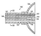
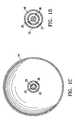
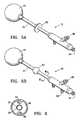
- FIG. 1Ais a schematic view of a device embodying features of the invention including a cavity filling member.
- FIG. 1Bis a longitudinal cross sectional view of the device along lines 1 B- 1 B in FIG. 1A .
- FIG. 1Cis a transverse cross sectional view of the device taken along lines 1 C- 1 C in FIG. 1A .
- FIG. 1Dis a transverse cross sectional view of the device taken along lines 1 D- 1 D.
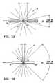
- FIGS. 2A and 2Bare diagramatic views of a radiation shielding component which includes a proximal radiation shield and a distal radiation shield.
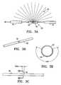
- FIG. 3Ais a diagramatic view of a central radiation shield which is configured to partially encircle the treatment location so as to control the emissions from a radiation source at the treatment location.
- FIG. 3Bis a perspective view of a central radiation shield including a window.
- FIG. 3Cis an elevational view of the central radiation shield shown in FIG. 3B .
- FIG. 3Dis a transverse cross sectional view of the central radiation shield taken along lines 3 D- 3 D in FIG. 3C .
- FIG. 3Eis a perspective view of a central radiation shield including a window similar to but longer than the window shown in FIG. 3B .
- FIG. 3Fis an elevational view of the central radiation shield shown in FIG. 3E .
- FIG. 3Gis a transverse cross sectional view of the central radiation shield taken along lines 3 G- 3 G in FIG. 3F .
- FIGS. 4A and 4Bare transverse cross sectional views of an elongated shaft of a device embodying features of the invention which includes three chambers, some of which contain radiation shields.
- FIG. 5Ais perspective view of a device embodying features of the invention including a sealing member which is formed of an adhesive material.
- FIG. 5Bis a perspective view of a device embodying features of the invention including an inflatable sealing member.
- FIG. 6is a cross sectional view of the device shown in FIG. 5B taken along line 6 - 6 .
- FIGS. 7A and 7Bshow the steps of a method for treating a body cavity utilizing the device shown in FIG. 5B .
- FIG. 8is a partial elevational view of a distal portion of a radiation balloon catheter device having a circular radiation shield region on the balloon.
- FIGS. 9A and 9Bare partial elevational views of distal portions of radiation balloon catheter devices having elongated radiation shield regions (oval and lenticular shaped) on the balloon.
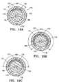
- FIGS. 10A and 10Bare partial elevational views of distal portions of radiation balloon catheter devices having radiation shield regions on the distal and proximal ends of the balloons.
- the regionsmay be hemispherical or cover only a side of the end of the balloon.
- FIGS. 11A and 11Bare partial elevational views of distal portions of radiation balloon catheter devices having locator or orientation marks on the balloon.
- FIG. 12is a partial longitudinal view, in section, of the elongated shaft of a catheter device having a radiation absorbing shield to control radiation emissions.
- FIG. 13is a transverse cross-sectional view of the device shown in FIG. 12 taken along the lines 13 - 13 .
- FIG. 14is a transverse cross-sectional view of a device similar to that shown in FIG. 12 with separate lumens for inflation of the balloon and vacuum delivery.
- FIG. 15is a transverse cross-sectional view of a device similar to that shown in FIG. 12 with an alternative structure with a radiation shield fixed within a recess of the inner member within the balloon.
- FIG. 16a transverse cross-sectional view of a device similar to that shown in FIG. 12 with a radiation shield fixed within an inner lumen within the inner member within the balloon.
- FIG. 17is an elevational view, partially in section of a device similar to that shown in FIG. 12 with a balloon having a pocket configured to receive radiation absorbing material such as contrast fluid.
- FIG. 18is a transverse cross-sectional view of the device shown in FIG. 17 .
- FIGS. 19A-Cillustrate another embodiment wherein a radiation shield is provided on an inner catheter which is rotatably disposed within an inner lumen of an outer catheter to reduce radiation on one side of the catheter.
- the present inventionprovides devices and methods for treatment of a patient's body cavity or other intracorporeal site.
- devices and methods having features of the inventionare used to deliver treatment into a biopsy site or into a cavity or site left after removal of cancerous tissue from the patient's body.
- a tissue treating device 10 embodying features of the inventionincludes an elongated shaft 12 with a treatment location 14 in a distal portion 16 of the elongate shaft 12 .
- the treatment location 14includes a source for a treatment agent such as a radiation source 18 which has a push rod 20 for advancing the source within the device.
- the elongate shaft 12has a delivery lumen 22 which leads to treatment location 14 for advancement of the radiation source 18 to the treatment location.
- the elongated shaft 12also includes a delivery port 24 in fluid communication with the delivery lumen 22 through which the radiation source 18 is advanced.
- the device 10has one or more radiation shielding components 26 disposed about the radiation source 18 deployed within the treatment location to control in part the radiation emitted from the radiation source.
- the radiation shielding component 26is designed to reduce or minimize damaging irradiation of healthy tissue surrounding a body cavity while treating nearby areas having diseased tissue with radiation emitted from the radiation source 18 .
- the radiation shielding component 26includes at least one radiation shield 28 which is configured to be deployed proximal to, distal to, or within the treatment location 14 .
- the radiation shielding component 26has a pair of radiation shields including a proximal radiation shield 30 and a distal radiation shield 32 ( FIGS. 2A-2B ).
- the proximal shield 30is deployed proximal to the treatment location 14 and the distal shield 32 is deployed distal to the treatment location 14 .
- the shieldsallow for control, at least in part, of the axial and near axial emissions from the proximal and distal end portions of the elongate shaft 12 .
- the radiation dispersal pattern 34When the proximal end of distal radiation shield 32 is adjacent the radiation source 18 and the distal end of the proximal radiation shield 30 is adjacent the radiation source 18 the radiation dispersal pattern 34 would be a small cone emanating from the radiation source 18 . As the proximal end of the distal radiation shield 32 and the distal end of the proximal radiation shield 30 move further away from the radiation source 18 the radiation dispersal pattern 34 increases to a near spherical shape having an axial cone of shielding 36 expanding from the radiation source 18 along the longitudinal axis in both directions.
- the pair of radiation shields 30 and 32are preferably configured to be adjustable to accommodate anatomical structural variations or to adjust treatment parameters.
- the radiation shielding component 26includes one or more radiation shields 28 .
- the radiation shields 28are formed of a suitably radiopaque metal or polymer containing at least in part a radiation absorbing material and are preferably tubular.
- the shieldsare preferably slidably disposed about the delivery lumen 22 of the device 10 .
- Suitable radiation absorbing materialsinclude tantalum, bismuth subcarbonate, barium sulfate, platinum, gold and tungsten.
- the radiation source 18 of the device 10can include a radiation source which is solid or liquid.
- Suitable liquid radiation sourcesinclude, for example, a liquid containing a radioactive iodine isotope (e.g., I 125 or I 131 ), a slurry of a solid isotope, for example, 198 Au or 169 Yb, or a gel containing a radioactive isotope.
- Liquid radiation sourcesare commercially available (e.g., Iotrex®, Proxima Therapeutics, Inc., Alpharetta, Ga.).
- the radiation source 18preferably includes brachytherapy seeds or other solid radiation sources used in radiation therapy, for example, a radioactive microsphere available from 3M Company of St. Paul, Minn.
- the radiation source 18is either preloaded into the device 10 at the time of manufacture or is loaded into the device 10 after placement into a body cavity of a patient.
- Solid radionuclides suitable for use with a device 10 embodying features of the present inventionare currently generally available as brachytherapy radiation sources (e.g., I-Plant.TM, Med-Tec, Orange City, Iowa.). Radiation may also be delivered by a device such as the x-ray tube of U.S. Pat. No. 6,319,188.
- the x-ray tubesare small, flexible and are believed to be capable of being maneuverable enough to reach the desired location within a patient's body.
- One embodiment of the device 10also includes a vacuum lumen 38 which is configured to be in fluid communication with a vacuum source (not shown) and one or more vacuum ports 42 in the exterior of the distal portion of the elongated shaft 12 .
- the vacuum ports 42are in fluid communication with the vacuum lumen 38 to provide a vacuum within a body cavity or other intracorporeal site.
- the device 10includes a cavity filling member 44 on the distal portion 16 of the shaft 12 which at least in part fills the body cavity or other site.
- the cavity filling member 44can be inflatable or expandable and configured to contact tissue surfaces defining the body cavity.
- the cavity filling member 44is in fluid communication with a first inflation lumen 46 which has a first inflation port 48 .
- the vacuum ports 42 for the vacuum lumen 38preferably are located proximal and or distal to the cavity filling member 44 which at least partially fills the body cavity.
- a central radiation shield 50shown in FIG. 3A , can be deployed between the proximal 30 and distal 32 radiation shields.
- the central radiation shield 50preferably defines at least in part a window 52 to allow for dispersal of radiation from a radiation source 18 .
- the central radiation shield 50defines a window 52 which may have a variable length as shown in FIGS. 3B-G .
- the length of the window 52is between about 2 millimeters to 5 centimeters and the central radiation shield is tubular in shape.
- the shielding areais arcuate with an angular range from about 20° to about 240°.
- the central radiation shield 50comprises a pair of separately rotatable members to allow for adjusting the window dimensions. The central radiation shield 50 is rotated or advanced to position the window 52 near the target tissue.
- FIGS. 4A and 4BAnother embodiment of the invention shown in FIGS. 4A and 4B includes a partitioned shaft 54 disposed about the delivery shaft 20 .
- the partitioned shaft 54has a lumen 56 which is divided into at least two chambers 58 by spacing elements 60 .
- Radiation shields 28are configured to be inserted into one or more chambers 58 through the proximal end of the elongate shaft 12 to surround at least a portion of the treatment location 14 .
- the radiation shields 28reduce or minimize irradiation of healthy portions of the body cavity while treating nearby areas with the radiation source 18 .
- the radiation shield 28has varying densities acting as a filter to allow for some controlled amount of radiation to pass through yielding a non-symmetric radiation dosing.
- the radiation shields 28are constructed of sintered metal to block radiation and still allow for a fluid pathway for suction or vacuum of the body cavity.
- the devicein another embodiment of the invention depicted in FIGS. 5A , 5 B and 6 the device includes an elongate shaft 12 with a sealing member 62 located on the elongate shaft 12 to seal the passageway 64 through which the device 10 is advanced.
- the sealing membercan be inflated via a second inflation lumen 66 ( FIGS. 5B and 6A ) which is in fluid communication with a second inflation port 68 on the proximal end of the elongate shaft 12 .
- the sealing member 62allows for closer contact with the walls of the passageway 64 .
- the device 10also includes a cavity filling member 44 which at least in part fills the body cavity and which is inflatable or expandable.
- the sealing member 62is located on the elongate shaft 12 proximal to the distal end of the elongate shaft.
- the device 10can include a sealing member 62 formed of a flange or cuff having an adhesive distal face and located toward the proximal end of the elongate shaft 12 .
- the sealing member 62preferably is configured to form a seal in the passageway 64 leading to the body cavity by adhering to a patient's skin.
- the device 10preferably includes a vacuum lumen 38 configured to be in fluid communication with a proximal vacuum source and one or more vacuum ports 42 preferably proximal and or distal to the cavity filling member 44 .
- Application of a vacuum within the vacuum lumen 38aspirates fluid in the cavity through one or more vacuum ports 42 and pulls tissue surrounding the cavity onto the exterior of the cavity filling member 44 deployed within the cavity.
- the sealing member 62preferably is expanded or expandable, such as a balloon, and configured to minimize the loss of vacuum within the body cavity when a vacuum is developed.
- a device 10 having features of the inventioncan include contoured pads for use on the elongate shaft 12 of the device 10 .
- the contoured padsare provided on the proximal portion of the elongated shaft 12 of the device 10 and are configured to cover a portion of the shaft.
- the contoured padspreferably are comprised of material having soft tapered edges to minimize irritation to the skin caused by movement or dressing and undressing.
- the padsare taped externally to the patient or alternatively are attached to the patient with a double sided tape or adhesive material.
- a device 10 having features of the inventioncan be provided, at least in part, with a lubricious coating, such as a hydrophilic material.
- a lubricious coatingsuch as a hydrophilic material.
- the lubricious coatingpreferably is applied to the elongate shaft 12 or to the cavity filling member 44 , if one is present, to reduce sticking and friction during insertion of a device 10 .
- Hydrophilic coatingssuch as those provided by AST, Surmodics, TUA Systems, Hydromer, or STS Biopolymers are suitable.
- a device 10 having features of the inventionmay also include an antimicrobial coating that covers all or a portion of the device 10 to minimize the risk of introducing of an infection during extended treatments.
- the antimicrobial coatingpreferably is comprised of silver ions impregnated into a hydrophilic carrier. Alternatively the silver ions are implanted onto the surface of the device 10 by ion beam deposition.
- the antimicrobial coatingpreferably is be comprised of an antiseptic or disinfectant such as chlorhexadiene, benzyl chloride or other suitable biocompatible antimicrobial materials impregnated into hydrophilic coatings.
- Antimicrobial coatingssuch as those provided by Spire, AST, Algon, Surfacine, Ion Fusion, or Bacterin International would be suitable.
- a cuff member covered with the antimicrobial coatingis provided on the elongated shaft of the delivery device 10 at the point where the device 10 enters the skin.
- FIGS. 7A and 7BA method for treating a body cavity 70 of a patient is shown in FIGS. 7A and 7B .
- the methodincludes delivering a radiation source 18 to a body cavity 70 to treat the desired tissue adjacent a device 10 embodying features of the invention while minimizing damaging irradiation of healthy tissue.
- the methodincludes inserting a device 10 embodying features of the invention into the body cavity 70 , positioning a radiation shielding component 26 to shield healthy tissue in the body cavity 70 and positioning a source for a treatment agent, such as radiation source 18 within the treatment location 14 in a distal portion 16 of the shaft 12 .
- a method for treating tissue adjacent a body cavity 70may also include sealing a passageway 64 leading to a body cavity 70 .
- the methodincludes inserting a device 10 embodying features of the invention into the body cavity 70 and sealing the passageway 64 leading to the body cavity 70 ( FIG. 7A ) and then at least in part contacting the passageway 64 with a sealing member 62 on the elongate shaft 12 ( FIG. 7B ).
- FIG. 8illustrates a radiation balloon catheter device 80 having a circular radiation absorbing region 81 on the balloon 82 of the catheter device.
- FIG. 9Aillustrates a radiation balloon catheter device 85 having an elongated radiation absorbing region 86 on balloon 87 .
- FIG. 9Billustrates an alternative structure to that shown in FIG. 9A where the elongated radiation region 86 b tapers at the ends thereof.
- FIGS. 10A and 10Billustrate alternative radiation balloon devices 90 A and 90 B where the radiation shield regions 91 A and 91 B are respectively located on the distal and proximal ends of the balloons.
- FIGS. 11A and 11Billustrate alternative locator marks on a radiation balloon catheter device such as shown in FIG. 8 .
- the locator marks 95are a series of longitudinally oriented marks both proximal and distal to the radiation absorbing region 96 on the balloon which may be formed of radiopaque materials.
- the locator marks 97are linear marks extending from the proximal and distal ends of the radiation shielding region 98 .
- FIGS. 12 and 13illustrate a radiation balloon catheter device 100 which has a shield lumen 101 configured to slidably receive radiation shield 102 , a radiation source lumen 103 for radiation source 104 and a vacuum lumen 105 for generating a vacuum within the biopsy cavity through port 106 .
- the radiation shield 102has an elongated shaft 107 for manipulation of the shield for the treatment. While not shown, the proximal end of the shaft 107 is provided with a wing or other extension or indicia to indicate the position of the shield.
- the radiation source 104has an elongated shaft 108 to facilitate movement of the radiation source to the desired therapeutic location within the catheter device.
- the vacuum lumen 105is utilized for delivery of inflation fluid to the interior of the cavity filling balloon 109 .
- FIG. 14is a transverse cross section of an alternative catheter device 110 similar to that shown in FIGS. 12 and 13 but with a separate inflation lumen 111 for delivery of inflation fluid to the interior of the cavity filling balloon (not shown).
- FIG. 15illustrates an alternative structure wherein the radiation shield 120 is fixed within a recess in the exterior of inner member 121
- FIG. 16is an alternate structure where the radiation shield 130 is secured within a third inner lumen 131 .
- FIGS. 17 and 18depict an alternative structure for a radiation balloon catheter device 160 embodying features of the invention.
- the balloon 161has an inner liner 162 that defines an inner chamber 163 within the balloon that receives contrast fluid from the inner lumen 164 .
- the inner liner 162 as shownis an envelope secured to the interior of the balloon, but it may be formed integrally with the balloon wall. Contrast fluid within the inner chamber 163 shields the tissue adjacent thereto from radiation to avoid tissue damage.
- FIG. 19Aillustrates a shaft 170 of an alternative device which has an outer catheter 171 with an inner lumen 172 , an inner catheter 173 rotatably disposed within inner lumen 172 and a radiation shield 174 on the inner catheter 173 .
- FIGS. 19B and 19Cillustrate the same concept except that the radiation shields 175 and 176 cover greater regions of the inner catheter 173 and provide greater angles of radiation attenuation as shown.
- the outer catheter 171has an inflatable cavity filling member (not shown) on a distal portion thereof as in the prior examples.
- the wall of outer catheter 171has at least one lumen 177 for directing inflation fluid to the interior of the cavity filling member.
- the outer catheter 121also has vacuum ports (not shown) proximal and distal to the cavity filling member on the distal portion of the device 170 .
- the wall of the outer catheter 171also has at least one lumen 178 which is in fluid communication with one or both of the vacuum ports.
- the inner catheter 173has a central inner lumen 179 configured to receive a radiation source 180 to provide a radiation dose.
- the devicemay be formed of conventional materials.
- the balloonis preferably formed of semi-compliant or non-compliant polymeric materials so that the balloon can be inflated to a predetermined diameter within the body cavity or other site.
Landscapes
- Health & Medical Sciences (AREA)
- Engineering & Computer Science (AREA)
- Biomedical Technology (AREA)
- Nuclear Medicine, Radiotherapy & Molecular Imaging (AREA)
- Surgery (AREA)
- Pathology (AREA)
- Heart & Thoracic Surgery (AREA)
- Radiology & Medical Imaging (AREA)
- Life Sciences & Earth Sciences (AREA)
- Animal Behavior & Ethology (AREA)
- General Health & Medical Sciences (AREA)
- Public Health (AREA)
- Veterinary Medicine (AREA)
- Radiation-Therapy Devices (AREA)
Abstract
Description
Claims (28)
Priority Applications (2)
| Application Number | Priority Date | Filing Date | Title |
|---|---|---|---|
| US12/386,100US8273006B2 (en) | 2005-11-18 | 2009-04-14 | Tissue irradiation |
| US13/608,522US20130006037A1 (en) | 2005-11-18 | 2012-09-10 | Tissue irradiation |
Applications Claiming Priority (6)
| Application Number | Priority Date | Filing Date | Title |
|---|---|---|---|
| US11/283,236US7413539B2 (en) | 2005-11-18 | 2005-11-18 | Treatment of a body cavity |
| US77426606P | 2006-02-16 | 2006-02-16 | |
| US81992006P | 2006-07-11 | 2006-07-11 | |
| US81991906P | 2006-07-11 | 2006-07-11 | |
| US11/593,678US7517310B2 (en) | 2005-11-18 | 2006-11-06 | Methods for tissue irradiation with shielding |
| US12/386,100US8273006B2 (en) | 2005-11-18 | 2009-04-14 | Tissue irradiation |
Related Parent Applications (1)
| Application Number | Title | Priority Date | Filing Date |
|---|---|---|---|
| US11/593,678ContinuationUS7517310B2 (en) | 2005-11-18 | 2006-11-06 | Methods for tissue irradiation with shielding |
Related Child Applications (1)
| Application Number | Title | Priority Date | Filing Date |
|---|---|---|---|
| US13/608,522ContinuationUS20130006037A1 (en) | 2005-11-18 | 2012-09-10 | Tissue irradiation |
Publications (2)
| Publication Number | Publication Date |
|---|---|
| US20090209805A1 US20090209805A1 (en) | 2009-08-20 |
| US8273006B2true US8273006B2 (en) | 2012-09-25 |
Family
ID=40955742
Family Applications (2)
| Application Number | Title | Priority Date | Filing Date |
|---|---|---|---|
| US12/386,100Active2027-08-03US8273006B2 (en) | 2005-11-18 | 2009-04-14 | Tissue irradiation |
| US13/608,522AbandonedUS20130006037A1 (en) | 2005-11-18 | 2012-09-10 | Tissue irradiation |
Family Applications After (1)
| Application Number | Title | Priority Date | Filing Date |
|---|---|---|---|
| US13/608,522AbandonedUS20130006037A1 (en) | 2005-11-18 | 2012-09-10 | Tissue irradiation |
Country Status (1)
| Country | Link |
|---|---|
| US (2) | US8273006B2 (en) |
Cited By (1)
| Publication number | Priority date | Publication date | Assignee | Title |
|---|---|---|---|---|
| US20110215260A1 (en)* | 2009-12-18 | 2011-09-08 | Timo Kleinwaechter | Applicator means for radiation therapy as well as radiation therapy device |
Families Citing this family (19)
| Publication number | Priority date | Publication date | Assignee | Title |
|---|---|---|---|---|
| US7662082B2 (en) | 2004-11-05 | 2010-02-16 | Theragenics Corporation | Expandable brachytherapy device |
| US20090188098A1 (en) | 2008-01-24 | 2009-07-30 | Senorx, Inc. | Multimen brachytherapy balloon catheter |
| US8546773B2 (en) | 2009-09-02 | 2013-10-01 | John P. Stokes | Irradiation system and method |
| US10589071B2 (en) | 2010-09-23 | 2020-03-17 | Best Medical International, Inc. | Multiple function balloon catheter |
| US10744307B2 (en) | 2010-09-23 | 2020-08-18 | Best Medical International, Inc. | Multi-purpose balloon catheter for intra cavity radiation delivery |
| WO2014021947A1 (en)* | 2012-07-31 | 2014-02-06 | University Of Iowa Research Foundation | Advanced rotating-shield brachytherapy and planning of the same |
| US10029118B2 (en)* | 2012-07-31 | 2018-07-24 | University Of Iowa Research Foundation | Advanced rotating-shield brachytherapy and planning of the same |
| WO2015023307A1 (en)* | 2012-10-05 | 2015-02-19 | The Regents Of The University Of California | Brachytherapy applicator and methods for generating anisotropic directional radiation profiles |
| EP2946567B1 (en)* | 2013-01-18 | 2020-02-26 | iRobot Corporation | Environmental management systems including mobile robots and methods using same |
| DE102013110375A1 (en)* | 2013-09-19 | 2015-03-19 | IDTM GmbH | Applicator and depot for a radioactive radiation source for brachytherapy |
| JP6684784B2 (en)* | 2014-09-26 | 2020-04-22 | コーニンクレッカ フィリップス エヌ ヴェKoninklijke Philips N.V. | Brachytherapy Two-stage localization of radioactive seeds |
| KR101794128B1 (en)* | 2016-07-01 | 2017-11-30 | 국립암센터 | Apparatus for body- inserting having controllable radiation direction |
| IL310828A (en) | 2017-03-31 | 2024-04-01 | Empyrean Medical Systems Inc | A three-dimensional beam that creates an x-ray radiation source |
| US10709475B2 (en)* | 2018-03-07 | 2020-07-14 | Edward J. Mikol | Pumping surgical cannula |
| US11672491B2 (en) | 2018-03-30 | 2023-06-13 | Empyrean Medical Systems, Inc. | Validation of therapeutic radiation treatment |
| US20200391052A1 (en)* | 2019-06-14 | 2020-12-17 | Sensus Healthcare, Inc. | Balloon applicator for directional intraoperative and brachy radiation therapy with conformal phantom for 3d anatomical image registration |
| US20240189620A1 (en)* | 2021-04-28 | 2024-06-13 | Arizona Board Of Regents On Behalf Of The University Of Arizona | Device and associated methods for precision radiation treatment |
| US20240082600A1 (en)* | 2021-09-10 | 2024-03-14 | Arnold M. Herskovic | Hyperthermia brachytherapy device and method for treating tumors |
| US12350515B1 (en)* | 2024-07-26 | 2025-07-08 | Arnold M. Herskovic | Variable volume brachytherapy stent, method for delivering variable dosimetries in brachytherapy |
Citations (129)
| Publication number | Priority date | Publication date | Assignee | Title |
|---|---|---|---|---|
| US3324847A (en) | 1964-06-01 | 1967-06-13 | Elias G Zoumboulis | Radioactive catheter |
| US3872856A (en) | 1971-06-09 | 1975-03-25 | Ralph S Clayton | Apparatus for treating the walls and floor of the pelvic cavity with radiation |
| US3975350A (en) | 1972-08-02 | 1976-08-17 | Princeton Polymer Laboratories, Incorporated | Hydrophilic or hydrogel carrier systems such as coatings, body implants and other articles |
| US4119094A (en) | 1977-08-08 | 1978-10-10 | Biosearch Medical Products Inc. | Coated substrate having a low coefficient of friction hydrophilic coating and a method of making the same |
| US4690677A (en) | 1985-09-25 | 1987-09-01 | Daltex Medical Sciences, Inc. | Urine collection system for females |
| US4763642A (en) | 1986-04-07 | 1988-08-16 | Horowitz Bruce S | Intracavitational brachytherapy |
| US4998930A (en) | 1988-08-03 | 1991-03-12 | Phototherapeutic Systems | Intracavity laser phototherapy method |
| US5059166A (en) | 1989-12-11 | 1991-10-22 | Medical Innovative Technologies R & D Limited Partnership | Intra-arterial stent with the capability to inhibit intimal hyperplasia |
| US5106360A (en) | 1987-09-17 | 1992-04-21 | Olympus Optical Co., Ltd. | Thermotherapeutic apparatus |
| US5167622A (en) | 1990-12-07 | 1992-12-01 | Smiths Industries Medical Systems, Inc. | Triple conduit suction catheter |
| US5227969A (en) | 1988-08-01 | 1993-07-13 | W. L. Systems, Inc. | Manipulable three-dimensional projection imaging method |
| US5259847A (en) | 1992-06-25 | 1993-11-09 | Montefiore Hospital And Medical Center | Catheter to maintain minimally invasive access for exchanging internal biliary stents |
| US5302168A (en) | 1991-09-05 | 1994-04-12 | Hess Robert L | Method and apparatus for restenosis treatment |
| US5312356A (en) | 1989-05-22 | 1994-05-17 | Target Therapeutics | Catheter with low-friction distal segment |
| US5314518A (en) | 1991-06-24 | 1994-05-24 | Sumitomo Electric Industries, Ltd. | Method for producing glass preform for optical fiber |
| US5342305A (en) | 1992-08-13 | 1994-08-30 | Cordis Corporation | Variable distention angioplasty balloon assembly |
| US5381504A (en) | 1993-11-15 | 1995-01-10 | Minnesota Mining And Manufacturing Company | Optical fiber element having a permanent protective coating with a Shore D hardness value of 65 or more |
| EP0642766A2 (en) | 1993-09-15 | 1995-03-15 | United States Surgical Corporation | Manipulator apparatus |
| US5417687A (en) | 1993-04-30 | 1995-05-23 | Medical Scientific, Inc. | Bipolar electrosurgical trocar |
| US5428658A (en) | 1994-01-21 | 1995-06-27 | Photoelectron Corporation | X-ray source with flexible probe |
| US5429582A (en) | 1991-06-14 | 1995-07-04 | Williams; Jeffery A. | Tumor treatment |
| US5535817A (en) | 1989-07-28 | 1996-07-16 | Uop | Sorption cooling process and apparatus |
| US5566221A (en) | 1994-07-12 | 1996-10-15 | Photoelectron Corporation | Apparatus for applying a predetermined x-radiation flux to an interior surface of a body cavity |
| US5603991A (en) | 1995-09-29 | 1997-02-18 | Target Therapeutics, Inc. | Method for coating catheter lumens |
| WO1997012540A1 (en) | 1995-10-06 | 1997-04-10 | Photoelectron Corporation | Improved apparatus for applying x-rays to an interior surface of a body cavity |
| US5621780A (en) | 1990-09-05 | 1997-04-15 | Photoelectron Corporation | X-ray apparatus for applying a predetermined flux to an interior surface of a body cavity |
| EP0536440B1 (en) | 1991-10-11 | 1997-05-28 | Erbe Elektromedizin GmbH | H.F. surgical instrument for cutting and coagulating |
| US5653683A (en) | 1995-02-28 | 1997-08-05 | D'andrea; Mark A. | Intracavitary catheter for use in therapeutic radiation procedures |
| US5662580A (en) | 1994-12-08 | 1997-09-02 | Neocardia, Llc | Combined angioplasty and intravascular radiotherapy method and apparatus |
| US5704926A (en) | 1994-11-23 | 1998-01-06 | Navarre Biomedical, Ltd. | Flexible catheter |
| WO1998015315A1 (en) | 1996-10-07 | 1998-04-16 | Proxima Therapeutics Inc. | Inflatable devices for tumor treatment |
| JPH10137250A (en) | 1996-11-07 | 1998-05-26 | Olympus Optical Co Ltd | Suction biopsy tool |
| US5759173A (en) | 1994-11-23 | 1998-06-02 | Micro Interventional Systems | High torque balloon catheter |
| US5782742A (en) | 1997-01-31 | 1998-07-21 | Cardiovascular Dynamics, Inc. | Radiation delivery balloon |
| US5820594A (en) | 1994-01-31 | 1998-10-13 | Cordis Corporation | Balloon catheter |
| US5863285A (en) | 1997-01-30 | 1999-01-26 | Cordis Corporation | Balloon catheter with radioactive means |
| EP0867200A3 (en) | 1997-03-28 | 1999-04-07 | Navius Corporation | Intravascular radiation delivery device |
| US5908406A (en) | 1996-01-31 | 1999-06-01 | E. I. Du Pont De Nemours And Company | Dilatation catheter balloons with improved puncture resistance |
| US5913813A (en) | 1997-07-24 | 1999-06-22 | Proxima Therapeutics, Inc. | Double-wall balloon catheter for treatment of proliferative tissue |
| US5916143A (en) | 1996-04-30 | 1999-06-29 | Apple; Marc G. | Brachytherapy catheter system |
| US5919473A (en) | 1997-05-12 | 1999-07-06 | Elkhoury; George F. | Methods and devices for delivering opioid analgesics to wounds via a subdermal implant |
| WO1999034869A1 (en) | 1998-01-08 | 1999-07-15 | Nucletron B.V. | Improved method and apparatus for treating a blood vessel lesion |
| US5924973A (en) | 1996-09-26 | 1999-07-20 | The Trustees Of Columbia University In The City Of New York | Method of treating a disease process in a luminal structure |
| US5935098A (en) | 1996-12-23 | 1999-08-10 | Conceptus, Inc. | Apparatus and method for accessing and manipulating the uterus |
| US5993972A (en) | 1996-08-26 | 1999-11-30 | Tyndale Plains-Hunter, Ltd. | Hydrophilic and hydrophobic polyether polyurethanes and uses therefor |
| US6036631A (en) | 1998-03-09 | 2000-03-14 | Urologix, Inc. | Device and method for intracavitary cancer treatment |
| US6086970A (en) | 1998-04-28 | 2000-07-11 | Scimed Life Systems, Inc. | Lubricious surface extruded tubular members for medical devices |
| US6093142A (en) | 1998-04-30 | 2000-07-25 | Medtronic Inc. | Device for in vivo radiation delivery and method for delivery |
| US6095966A (en) | 1997-02-21 | 2000-08-01 | Xrt Corp. | X-ray device having a dilation structure for delivering localized radiation to an interior of a body |
| US6143013A (en) | 1995-04-28 | 2000-11-07 | Target Therapeutics, Inc. | High performance braided catheter |
| EP1070514A1 (en) | 1999-07-23 | 2001-01-24 | Nucletron B.V. | Apparatus and method for temporarily inserting a radioactive source in an animal body |
| US6200257B1 (en) | 1999-03-24 | 2001-03-13 | Proxima Therapeutics, Inc. | Catheter with permeable hydrogel membrane |
| US6217565B1 (en) | 1998-07-16 | 2001-04-17 | Mark Cohen | Reinforced variable stiffness tubing |
| JP2001120561A (en) | 1999-10-27 | 2001-05-08 | Olympus Optical Co Ltd | Treatment tool for endoscope |
| US6251059B1 (en) | 1997-09-11 | 2001-06-26 | Cook Incorporated | Medical radiation treatment delivery apparatus |
| US6256529B1 (en) | 1995-07-26 | 2001-07-03 | Burdette Medical Systems, Inc. | Virtual reality 3D visualization for surgical procedures |
| US20010016725A1 (en) | 1991-07-16 | 2001-08-23 | Kirsten L. Valley | Endovascular system for arresting the heart |
| US6282142B1 (en) | 1999-10-13 | 2001-08-28 | Oki Electric Industry Co., Ltd. | Semiconductor memory device |
| US20010049464A1 (en) | 1999-06-23 | 2001-12-06 | Robert A. Ganz | Therapeutic method and apparatus for debilitating or killing microorganisms within the body |
| US20010051669A1 (en) | 1998-10-07 | 2001-12-13 | Mcghee Diane | Lubricious coating |
| RU2177350C2 (en) | 1996-04-04 | 2001-12-27 | Новосте Корпорейшн | Radiation therapy for treating cardiovascular system diseases |
| US20020045893A1 (en) | 1999-08-23 | 2002-04-18 | Miriam Lane | Endovascular cryotreatment catheter |
| US6378137B1 (en) | 1997-10-01 | 2002-04-30 | Ansell Shah Alam Sdn Bhd | Powder-free medical gloves |
| US6390968B1 (en) | 2000-06-07 | 2002-05-21 | Paxton Equities, Llc | Cervical applicator for high dose radiation brachytherapy |
| US6390967B1 (en) | 2000-09-14 | 2002-05-21 | Xoft Microtube, Inc. | Radiation for inhibiting hyperplasia after intravascular intervention |
| US6398708B1 (en) | 1996-02-29 | 2002-06-04 | Scimed Life Systems, Inc. | Perfusion balloon and radioactive wire delivery system |
| US6413203B1 (en) | 1998-09-16 | 2002-07-02 | Scimed Life Systems, Inc. | Method and apparatus for positioning radioactive fluids within a body lumen |
| US6416492B1 (en) | 2000-09-28 | 2002-07-09 | Scimed Life Systems, Inc. | Radiation delivery system utilizing intravascular ultrasound |
| US20020095114A1 (en) | 2001-01-17 | 2002-07-18 | Maria Palasis | Therapeutic delivery balloon |
| US6458069B1 (en) | 1998-02-19 | 2002-10-01 | Endology, Inc. | Multi layer radiation delivery balloon |
| US6482142B1 (en) | 1997-07-24 | 2002-11-19 | Proxima Therapeutics, Inc. | Asymmetric radiation dosing apparatus and method |
| US20020177804A1 (en) | 1992-08-13 | 2002-11-28 | Radiant Medical, Inc. | Heat transfer catcheters methods of making and using same |
| US6512942B1 (en) | 1997-11-24 | 2003-01-28 | Computerized Medical Systems, Inc. | Radiation therapy and real time imaging of a patient treatment region |
| US6527693B2 (en) | 2001-01-30 | 2003-03-04 | Implant Sciences Corporation | Methods and implants for providing radiation to a patient |
| EP0693293B1 (en) | 1994-07-07 | 2003-03-26 | Terumo Kabushiki Kaisha | Medical instruments that exhibit surface lubricity when wetted |
| US6540655B1 (en) | 2000-11-10 | 2003-04-01 | Scimed Life Systems, Inc. | Miniature x-ray unit |
| US6605030B2 (en) | 1998-11-09 | 2003-08-12 | The Trustees Of Columbia University In The City Of New York | Apparatus and method for treating a disease process in a luminal structure |
| US6610013B1 (en) | 1999-10-01 | 2003-08-26 | Life Imaging Systems, Inc. | 3D ultrasound-guided intraoperative prostate brachytherapy |
| US6615070B2 (en) | 2000-06-01 | 2003-09-02 | Georgia Tech Research Corporation | Automated planning volume contouring algorithm for adjuvant brachytherapy treatment planning in sarcoma |
| US6673006B2 (en) | 2001-06-15 | 2004-01-06 | Proxima Therapeutics, Inc. | Tissue positioning apparatus and method for protecting tissue from radiotherapy |
| US20040039437A1 (en) | 2002-08-13 | 2004-02-26 | Medtronic, Inc. | Medical device exhibiting improved adhesion between polymeric coating and substrate |
| US6706014B2 (en) | 2000-11-10 | 2004-03-16 | Scimed Life Systems, Inc. | Miniature x-ray unit |
| US20040054366A1 (en) | 1998-08-11 | 2004-03-18 | Arthrocare Corporation | Instrument for electrosurgical tissue treatment |
| US6723052B2 (en) | 2001-06-07 | 2004-04-20 | Stanley L. Mills | Echogenic medical device |
| US20040087827A1 (en) | 2002-11-06 | 2004-05-06 | Senorx | Vacuum device and method for treating tissue adjacent a body cavity |
| US6746392B2 (en) | 2001-06-20 | 2004-06-08 | Medtronic Ave, Inc. | Brachytherapy catheter with twisted lumens and methods of use |
| US20040116767A1 (en) | 2002-09-10 | 2004-06-17 | Lebovic Gail S. | Brachytherapy apparatus and methods of using same |
| US6752752B2 (en) | 2000-11-10 | 2004-06-22 | Scimed Life Systems, Inc. | Multi-source x-ray catheter |
| EP0853957B1 (en) | 1997-01-21 | 2004-06-30 | Cordis Corporation | Catheter having an expandable radioactive source |
| US6770058B1 (en) | 1997-03-11 | 2004-08-03 | Interventional Therapies, Llc | Treatment catheter insert |
| US20040260142A1 (en) | 2003-06-18 | 2004-12-23 | Lovoi Paul A. | Method for intraoperative radiation treatment of breast cancer |
| US20050061771A1 (en) | 2003-09-22 | 2005-03-24 | Scimed Life Systems, Inc. | Surface modified reinforcing member for medical device and method for making same |
| US20050080313A1 (en) | 2003-10-10 | 2005-04-14 | Stewart Daren L. | Applicator for radiation treatment of a cavity |
| WO2005039655A1 (en) | 2003-10-16 | 2005-05-06 | Kimberly-Clark Worldwide, Inc. | Method for reducing odor using metal-modified silica particles |
| WO2005039665A1 (en) | 2003-10-23 | 2005-05-06 | Sherwood Services Ag | Lubricant compositions, their preparation and articles coated therewith |
| US20050124843A1 (en) | 2003-12-09 | 2005-06-09 | Washington University | Method and apparatus for delivering targeted therapy to a patient |
| EP0719571B1 (en) | 1994-12-27 | 2005-06-15 | Olympus Optical Co., Ltd. | Medical apparatus |
| US20050240073A1 (en) | 2004-04-26 | 2005-10-27 | Apffelstaedt Justus P | Devices and methods to conform and treat body cavities |
| US20060020256A1 (en) | 2004-07-20 | 2006-01-26 | Barbara Bell | Reinforced venous access catheter |
| US20060100475A1 (en) | 2004-11-05 | 2006-05-11 | White Jack C | Expandable brachytherapy device |
| US20060116546A1 (en) | 2004-10-04 | 2006-06-01 | Eng Tony Y | System and method for high dose rate radiation intracavitary brachytherapy |
| US20060136051A1 (en) | 1998-07-27 | 2006-06-22 | Icon Interventional Systems, Inc. | Coated medical device |
| US20060167416A1 (en) | 2004-11-23 | 2006-07-27 | Mark Mathis | Steerable device for accessing a target site and methods |
| US20060173235A1 (en) | 2003-06-18 | 2006-08-03 | Alex Lim | Gynecological brachytherapy applicator and system |
| US20060173233A1 (en) | 2003-06-18 | 2006-08-03 | Lovoi Paul A | Brachytherapy applicator for delivery and assessment of low-level ionizing radiation therapy and methods of use |
| US7098463B2 (en) | 2003-03-03 | 2006-08-29 | Heuris Pharma, Llc | Three-dimensional dosimeter for penetrating radiation and method of use |
| US20060205992A1 (en) | 2002-11-06 | 2006-09-14 | Senorx, Inc. | Temporary catheter for biopsy site tissue fixation |
| US20070005003A1 (en) | 2003-12-31 | 2007-01-04 | Patterson Ryan C | Reinforced multi-lumen catheter |
| EP1402922B1 (en) | 2002-09-27 | 2007-02-07 | Nucletron B.V. | Device for radiation treatment of proliferative tissue surrounding a cavity in an animal body |
| US20070055144A1 (en) | 2004-08-12 | 2007-03-08 | Navotek Medical Ltd. | Medical Treatment System and Method |
| US7201715B2 (en) | 1997-11-24 | 2007-04-10 | Computerized Medical Systems, Inc. | Real time brachytherapy spatial registration and visualization system |
| US20070167666A1 (en) | 2005-11-18 | 2007-07-19 | Senorx, Inc. | Asymmetrical irradiation of a body cavity |
| US20070191667A1 (en) | 2005-11-18 | 2007-08-16 | Senorx, Inc. | Methods for tissue irradiation with shielding |
| US20070270627A1 (en) | 2005-12-16 | 2007-11-22 | North American Scientific | Brachytherapy apparatus for asymmetrical body cavities |
| US20080057298A1 (en) | 2006-08-29 | 2008-03-06 | Surmodics, Inc. | Low friction particulate coatings |
| US20080091055A1 (en) | 2006-10-08 | 2008-04-17 | Cianna Medical, Inc. | Expandable brachytherapy apparatus and methods for using them |
| US7407476B2 (en)* | 2005-11-18 | 2008-08-05 | Senorx, Inc. | Tissue irradiation with shielding |
| US20080221384A1 (en) | 2006-06-02 | 2008-09-11 | Cianna Medical, Inc. | Expandable brachytherapy apparatus and methods for using them |
| US20080221444A1 (en) | 2007-03-07 | 2008-09-11 | Ritchie Paul G | Integrated Imaging and Biopsy System with Integrated Surgical, Therapy, and Diagnostic Devices |
| US20080228025A1 (en) | 2007-03-12 | 2008-09-18 | Senorx, Inc. | Radiation catheter with multilayered balloon |
| US20080228150A1 (en) | 2007-03-15 | 2008-09-18 | Senorx, Inc. | Soft body catheter with low friction lumen |
| EP1051990B1 (en) | 1998-01-30 | 2008-10-29 | Kaneka Corporation | Balloon catheter and method of production |
| US20080287801A1 (en) | 2006-08-14 | 2008-11-20 | Novelis, Inc. | Imaging device, imaging system, and methods of imaging |
| US7476235B2 (en) | 2001-12-14 | 2009-01-13 | The Regents Of The University Of California | Catheter based balloon for therapy modification and positioning of tissue |
| US7513861B2 (en) | 2003-06-18 | 2009-04-07 | Xoft, Inc. | Real time verification in radiation treatment |
| US20090188098A1 (en) | 2008-01-24 | 2009-07-30 | Senorx, Inc. | Multimen brachytherapy balloon catheter |
| EP1618924B1 (en) | 2004-07-20 | 2009-09-09 | Nucletron B.V. | Device for radiation treatment of proliferative tissue surrounding a cavity in an animal body |
| US7885382B2 (en) | 2003-10-10 | 2011-02-08 | Xoft, Inc. | Radiation treatment using x-ray source |
| US7887476B2 (en) | 2005-11-10 | 2011-02-15 | Cianna Medical, Inc. | Helical brachytherapy apparatus and methods of using same |
Family Cites Families (4)
| Publication number | Priority date | Publication date | Assignee | Title |
|---|---|---|---|---|
| US642766A (en)* | 1899-09-18 | 1900-02-06 | John Thomson | Water-meter. |
| IT1288728B1 (en)* | 1996-10-04 | 1998-09-24 | Bridgestone Firestone Tech | METALLIC HEEL FOR TIRES AND METHOD FOR ITS REALIZATION. |
| US6983754B1 (en)* | 2002-10-11 | 2006-01-10 | Anderson Randy M | Bag washing apparatus and method |
| US7071097B2 (en)* | 2004-07-09 | 2006-07-04 | International Business Machines Corporation | Method for improved process latitude by elongated via integration |
- 2009
- 2009-04-14USUS12/386,100patent/US8273006B2/enactiveActive
- 2012
- 2012-09-10USUS13/608,522patent/US20130006037A1/ennot_activeAbandoned
Patent Citations (160)
| Publication number | Priority date | Publication date | Assignee | Title |
|---|---|---|---|---|
| US3324847A (en) | 1964-06-01 | 1967-06-13 | Elias G Zoumboulis | Radioactive catheter |
| US3872856A (en) | 1971-06-09 | 1975-03-25 | Ralph S Clayton | Apparatus for treating the walls and floor of the pelvic cavity with radiation |
| US3975350A (en) | 1972-08-02 | 1976-08-17 | Princeton Polymer Laboratories, Incorporated | Hydrophilic or hydrogel carrier systems such as coatings, body implants and other articles |
| US4119094A (en) | 1977-08-08 | 1978-10-10 | Biosearch Medical Products Inc. | Coated substrate having a low coefficient of friction hydrophilic coating and a method of making the same |
| US4690677A (en) | 1985-09-25 | 1987-09-01 | Daltex Medical Sciences, Inc. | Urine collection system for females |
| US4763642A (en) | 1986-04-07 | 1988-08-16 | Horowitz Bruce S | Intracavitational brachytherapy |
| US5106360A (en) | 1987-09-17 | 1992-04-21 | Olympus Optical Co., Ltd. | Thermotherapeutic apparatus |
| US5227969A (en) | 1988-08-01 | 1993-07-13 | W. L. Systems, Inc. | Manipulable three-dimensional projection imaging method |
| US4998930A (en) | 1988-08-03 | 1991-03-12 | Phototherapeutic Systems | Intracavity laser phototherapy method |
| US5312356A (en) | 1989-05-22 | 1994-05-17 | Target Therapeutics | Catheter with low-friction distal segment |
| US5535817A (en) | 1989-07-28 | 1996-07-16 | Uop | Sorption cooling process and apparatus |
| US5059166A (en) | 1989-12-11 | 1991-10-22 | Medical Innovative Technologies R & D Limited Partnership | Intra-arterial stent with the capability to inhibit intimal hyperplasia |
| US5621780A (en) | 1990-09-05 | 1997-04-15 | Photoelectron Corporation | X-ray apparatus for applying a predetermined flux to an interior surface of a body cavity |
| US5167622A (en) | 1990-12-07 | 1992-12-01 | Smiths Industries Medical Systems, Inc. | Triple conduit suction catheter |
| US5429582A (en) | 1991-06-14 | 1995-07-04 | Williams; Jeffery A. | Tumor treatment |
| US6022308A (en) | 1991-06-14 | 2000-02-08 | Proxima Therapeutics, Inc. | Tumor treatment |
| US5611767A (en) | 1991-06-14 | 1997-03-18 | Oncocath, Inc. | Radiation treatment of tumors using inflatable devices |
| US6083148A (en) | 1991-06-14 | 2000-07-04 | Proxima Therapeutics, Inc. | Tumor treatment |
| US5931774A (en) | 1991-06-14 | 1999-08-03 | Proxima Therapeutics, Inc. | Inflatable devices for tumor treatment |
| US5314518A (en) | 1991-06-24 | 1994-05-24 | Sumitomo Electric Industries, Ltd. | Method for producing glass preform for optical fiber |
| US6913600B2 (en) | 1991-07-16 | 2005-07-05 | Heartport, Inc. | Endovascular system for arresting the heart |
| US20010016725A1 (en) | 1991-07-16 | 2001-08-23 | Kirsten L. Valley | Endovascular system for arresting the heart |
| US5302168A (en) | 1991-09-05 | 1994-04-12 | Hess Robert L | Method and apparatus for restenosis treatment |
| US5411466A (en) | 1991-09-05 | 1995-05-02 | Robert L. Hess | Apparatus for restenosis treatment |
| EP0536440B1 (en) | 1991-10-11 | 1997-05-28 | Erbe Elektromedizin GmbH | H.F. surgical instrument for cutting and coagulating |
| US5259847A (en) | 1992-06-25 | 1993-11-09 | Montefiore Hospital And Medical Center | Catheter to maintain minimally invasive access for exchanging internal biliary stents |
| US5342305A (en) | 1992-08-13 | 1994-08-30 | Cordis Corporation | Variable distention angioplasty balloon assembly |
| US20020177804A1 (en) | 1992-08-13 | 2002-11-28 | Radiant Medical, Inc. | Heat transfer catcheters methods of making and using same |
| US5417687A (en) | 1993-04-30 | 1995-05-23 | Medical Scientific, Inc. | Bipolar electrosurgical trocar |
| EP0642766A2 (en) | 1993-09-15 | 1995-03-15 | United States Surgical Corporation | Manipulator apparatus |
| US5381504A (en) | 1993-11-15 | 1995-01-10 | Minnesota Mining And Manufacturing Company | Optical fiber element having a permanent protective coating with a Shore D hardness value of 65 or more |
| US5428658A (en) | 1994-01-21 | 1995-06-27 | Photoelectron Corporation | X-ray source with flexible probe |
| US5820594A (en) | 1994-01-31 | 1998-10-13 | Cordis Corporation | Balloon catheter |
| EP0693293B1 (en) | 1994-07-07 | 2003-03-26 | Terumo Kabushiki Kaisha | Medical instruments that exhibit surface lubricity when wetted |
| US5566221A (en) | 1994-07-12 | 1996-10-15 | Photoelectron Corporation | Apparatus for applying a predetermined x-radiation flux to an interior surface of a body cavity |
| US5704926A (en) | 1994-11-23 | 1998-01-06 | Navarre Biomedical, Ltd. | Flexible catheter |
| US5759173A (en) | 1994-11-23 | 1998-06-02 | Micro Interventional Systems | High torque balloon catheter |
| US5662580A (en) | 1994-12-08 | 1997-09-02 | Neocardia, Llc | Combined angioplasty and intravascular radiotherapy method and apparatus |
| EP0719571B1 (en) | 1994-12-27 | 2005-06-15 | Olympus Optical Co., Ltd. | Medical apparatus |
| US5720717A (en) | 1995-02-28 | 1998-02-24 | D'andrea; Mark A. | Intracavitary catheter for use in therapeutic radiation procedures |
| US5653683A (en) | 1995-02-28 | 1997-08-05 | D'andrea; Mark A. | Intracavitary catheter for use in therapeutic radiation procedures |
| US6143013A (en) | 1995-04-28 | 2000-11-07 | Target Therapeutics, Inc. | High performance braided catheter |
| US6256529B1 (en) | 1995-07-26 | 2001-07-03 | Burdette Medical Systems, Inc. | Virtual reality 3D visualization for surgical procedures |
| US7171255B2 (en) | 1995-07-26 | 2007-01-30 | Computerized Medical Systems, Inc. | Virtual reality 3D visualization for surgical procedures |
| US5603991A (en) | 1995-09-29 | 1997-02-18 | Target Therapeutics, Inc. | Method for coating catheter lumens |
| WO1997012540A1 (en) | 1995-10-06 | 1997-04-10 | Photoelectron Corporation | Improved apparatus for applying x-rays to an interior surface of a body cavity |
| US5908406A (en) | 1996-01-31 | 1999-06-01 | E. I. Du Pont De Nemours And Company | Dilatation catheter balloons with improved puncture resistance |
| US6398708B1 (en) | 1996-02-29 | 2002-06-04 | Scimed Life Systems, Inc. | Perfusion balloon and radioactive wire delivery system |
| RU2177350C2 (en) | 1996-04-04 | 2001-12-27 | Новосте Корпорейшн | Radiation therapy for treating cardiovascular system diseases |
| US5916143A (en) | 1996-04-30 | 1999-06-29 | Apple; Marc G. | Brachytherapy catheter system |
| US5993972A (en) | 1996-08-26 | 1999-11-30 | Tyndale Plains-Hunter, Ltd. | Hydrophilic and hydrophobic polyether polyurethanes and uses therefor |
| US5924973A (en) | 1996-09-26 | 1999-07-20 | The Trustees Of Columbia University In The City Of New York | Method of treating a disease process in a luminal structure |
| WO1998015315A1 (en) | 1996-10-07 | 1998-04-16 | Proxima Therapeutics Inc. | Inflatable devices for tumor treatment |
| JPH10137250A (en) | 1996-11-07 | 1998-05-26 | Olympus Optical Co Ltd | Suction biopsy tool |
| US5935098A (en) | 1996-12-23 | 1999-08-10 | Conceptus, Inc. | Apparatus and method for accessing and manipulating the uterus |
| EP0853957B1 (en) | 1997-01-21 | 2004-06-30 | Cordis Corporation | Catheter having an expandable radioactive source |
| US5863285A (en) | 1997-01-30 | 1999-01-26 | Cordis Corporation | Balloon catheter with radioactive means |
| US5782742A (en) | 1997-01-31 | 1998-07-21 | Cardiovascular Dynamics, Inc. | Radiation delivery balloon |
| US6095966A (en) | 1997-02-21 | 2000-08-01 | Xrt Corp. | X-ray device having a dilation structure for delivering localized radiation to an interior of a body |
| US6770058B1 (en) | 1997-03-11 | 2004-08-03 | Interventional Therapies, Llc | Treatment catheter insert |
| US6033357A (en) | 1997-03-28 | 2000-03-07 | Navius Corporation | Intravascular radiation delivery device |
| EP0867200A3 (en) | 1997-03-28 | 1999-04-07 | Navius Corporation | Intravascular radiation delivery device |
| US5919473A (en) | 1997-05-12 | 1999-07-06 | Elkhoury; George F. | Methods and devices for delivering opioid analgesics to wounds via a subdermal implant |
| US5913813A (en) | 1997-07-24 | 1999-06-22 | Proxima Therapeutics, Inc. | Double-wall balloon catheter for treatment of proliferative tissue |
| US6482142B1 (en) | 1997-07-24 | 2002-11-19 | Proxima Therapeutics, Inc. | Asymmetric radiation dosing apparatus and method |
| US6413204B1 (en) | 1997-07-24 | 2002-07-02 | Proxima Therapeutics, Inc. | Interstitial brachytherapy apparatus and method for treatment of proliferative tissue diseases |
| US6251059B1 (en) | 1997-09-11 | 2001-06-26 | Cook Incorporated | Medical radiation treatment delivery apparatus |
| US6378137B1 (en) | 1997-10-01 | 2002-04-30 | Ansell Shah Alam Sdn Bhd | Powder-free medical gloves |
| US6512942B1 (en) | 1997-11-24 | 2003-01-28 | Computerized Medical Systems, Inc. | Radiation therapy and real time imaging of a patient treatment region |
| US7201715B2 (en) | 1997-11-24 | 2007-04-10 | Computerized Medical Systems, Inc. | Real time brachytherapy spatial registration and visualization system |
| WO1999034869A1 (en) | 1998-01-08 | 1999-07-15 | Nucletron B.V. | Improved method and apparatus for treating a blood vessel lesion |
| EP1051990B1 (en) | 1998-01-30 | 2008-10-29 | Kaneka Corporation | Balloon catheter and method of production |
| US6458069B1 (en) | 1998-02-19 | 2002-10-01 | Endology, Inc. | Multi layer radiation delivery balloon |
| US6036631A (en) | 1998-03-09 | 2000-03-14 | Urologix, Inc. | Device and method for intracavitary cancer treatment |
| US6086970A (en) | 1998-04-28 | 2000-07-11 | Scimed Life Systems, Inc. | Lubricious surface extruded tubular members for medical devices |
| US6093142A (en) | 1998-04-30 | 2000-07-25 | Medtronic Inc. | Device for in vivo radiation delivery and method for delivery |
| US6217565B1 (en) | 1998-07-16 | 2001-04-17 | Mark Cohen | Reinforced variable stiffness tubing |
| US20060136051A1 (en) | 1998-07-27 | 2006-06-22 | Icon Interventional Systems, Inc. | Coated medical device |
| US20040054366A1 (en) | 1998-08-11 | 2004-03-18 | Arthrocare Corporation | Instrument for electrosurgical tissue treatment |
| US6413203B1 (en) | 1998-09-16 | 2002-07-02 | Scimed Life Systems, Inc. | Method and apparatus for positioning radioactive fluids within a body lumen |
| US20010051669A1 (en) | 1998-10-07 | 2001-12-13 | Mcghee Diane | Lubricious coating |
| US6605030B2 (en) | 1998-11-09 | 2003-08-12 | The Trustees Of Columbia University In The City Of New York | Apparatus and method for treating a disease process in a luminal structure |
| US6200257B1 (en) | 1999-03-24 | 2001-03-13 | Proxima Therapeutics, Inc. | Catheter with permeable hydrogel membrane |
| US20010049464A1 (en) | 1999-06-23 | 2001-12-06 | Robert A. Ganz | Therapeutic method and apparatus for debilitating or killing microorganisms within the body |
| EP1070514A1 (en) | 1999-07-23 | 2001-01-24 | Nucletron B.V. | Apparatus and method for temporarily inserting a radioactive source in an animal body |
| US20020045893A1 (en) | 1999-08-23 | 2002-04-18 | Miriam Lane | Endovascular cryotreatment catheter |
| US6610013B1 (en) | 1999-10-01 | 2003-08-26 | Life Imaging Systems, Inc. | 3D ultrasound-guided intraoperative prostate brachytherapy |
| US6282142B1 (en) | 1999-10-13 | 2001-08-28 | Oki Electric Industry Co., Ltd. | Semiconductor memory device |
| JP2001120561A (en) | 1999-10-27 | 2001-05-08 | Olympus Optical Co Ltd | Treatment tool for endoscope |
| US7107089B2 (en) | 2000-06-01 | 2006-09-12 | Georgia Tech Research Corporation | Automated planning volume contouring algorithm for adjuvant brachytherapy treatment planning in sarcoma |
| US6615070B2 (en) | 2000-06-01 | 2003-09-02 | Georgia Tech Research Corporation | Automated planning volume contouring algorithm for adjuvant brachytherapy treatment planning in sarcoma |
| US6390968B1 (en) | 2000-06-07 | 2002-05-21 | Paxton Equities, Llc | Cervical applicator for high dose radiation brachytherapy |
| US6390967B1 (en) | 2000-09-14 | 2002-05-21 | Xoft Microtube, Inc. | Radiation for inhibiting hyperplasia after intravascular intervention |
| US6416492B1 (en) | 2000-09-28 | 2002-07-09 | Scimed Life Systems, Inc. | Radiation delivery system utilizing intravascular ultrasound |
| US6540655B1 (en) | 2000-11-10 | 2003-04-01 | Scimed Life Systems, Inc. | Miniature x-ray unit |
| US6752752B2 (en) | 2000-11-10 | 2004-06-22 | Scimed Life Systems, Inc. | Multi-source x-ray catheter |
| US6706014B2 (en) | 2000-11-10 | 2004-03-16 | Scimed Life Systems, Inc. | Miniature x-ray unit |
| US20020095114A1 (en) | 2001-01-17 | 2002-07-18 | Maria Palasis | Therapeutic delivery balloon |
| US6527693B2 (en) | 2001-01-30 | 2003-03-04 | Implant Sciences Corporation | Methods and implants for providing radiation to a patient |
| US6723052B2 (en) | 2001-06-07 | 2004-04-20 | Stanley L. Mills | Echogenic medical device |
| US6673006B2 (en) | 2001-06-15 | 2004-01-06 | Proxima Therapeutics, Inc. | Tissue positioning apparatus and method for protecting tissue from radiotherapy |
| US6746392B2 (en) | 2001-06-20 | 2004-06-08 | Medtronic Ave, Inc. | Brachytherapy catheter with twisted lumens and methods of use |
| US7476235B2 (en) | 2001-12-14 | 2009-01-13 | The Regents Of The University Of California | Catheter based balloon for therapy modification and positioning of tissue |
| US20090171157A1 (en) | 2001-12-14 | 2009-07-02 | The Regents Of The University Of California | Catheter based balloon for therapy modification and positioning of tissue |
| US20040039437A1 (en) | 2002-08-13 | 2004-02-26 | Medtronic, Inc. | Medical device exhibiting improved adhesion between polymeric coating and substrate |
| US20040116767A1 (en) | 2002-09-10 | 2004-06-17 | Lebovic Gail S. | Brachytherapy apparatus and methods of using same |
| EP1402922B1 (en) | 2002-09-27 | 2007-02-07 | Nucletron B.V. | Device for radiation treatment of proliferative tissue surrounding a cavity in an animal body |
| US7404791B2 (en) | 2002-09-27 | 2008-07-29 | Nucletron B.V. | Device for radiation treatment of proliferative tissue surrounding a cavity in an animal body |
| US7214178B2 (en) | 2002-11-06 | 2007-05-08 | Senorx, Inc. | Vacuum device and method for treating tissue adjacent a body cavity |
| US6955641B2 (en) | 2002-11-06 | 2005-10-18 | Senorx, Inc. | Vacuum device and method for treating tissue adjacent a body cavity |
| US20050240074A1 (en) | 2002-11-06 | 2005-10-27 | Senorx, Inc. | Vacuum device and method for treating tissue adjacent a body cavity |
| US20050182286A1 (en) | 2002-11-06 | 2005-08-18 | Senorx, Inc. | Vacuum device and method for treating tissue adjacent a body cavity |
| US6923754B2 (en) | 2002-11-06 | 2005-08-02 | Senorx, Inc. | Vacuum device and method for treating tissue adjacent a body cavity |
| US20060205992A1 (en) | 2002-11-06 | 2006-09-14 | Senorx, Inc. | Temporary catheter for biopsy site tissue fixation |
| US20040087827A1 (en) | 2002-11-06 | 2004-05-06 | Senorx | Vacuum device and method for treating tissue adjacent a body cavity |
| US20080064915A1 (en) | 2002-11-06 | 2008-03-13 | Senorx, Inc. | Vacuum device and method for treating tissue adjacent a body cavity |
| US20040215048A1 (en) | 2002-11-06 | 2004-10-28 | Senorx, Inc. | Vacuum device and method for treating tissue adjacent a body cavity |
| US7098463B2 (en) | 2003-03-03 | 2006-08-29 | Heuris Pharma, Llc | Three-dimensional dosimeter for penetrating radiation and method of use |
| US20060173233A1 (en) | 2003-06-18 | 2006-08-03 | Lovoi Paul A | Brachytherapy applicator for delivery and assessment of low-level ionizing radiation therapy and methods of use |
| US7513861B2 (en) | 2003-06-18 | 2009-04-07 | Xoft, Inc. | Real time verification in radiation treatment |
| US20040260142A1 (en) | 2003-06-18 | 2004-12-23 | Lovoi Paul A. | Method for intraoperative radiation treatment of breast cancer |
| US20060173235A1 (en) | 2003-06-18 | 2006-08-03 | Alex Lim | Gynecological brachytherapy applicator and system |
| US7322929B2 (en) | 2003-06-18 | 2008-01-29 | Xoft, Inc. | Method for radiation treatment |
| US20050061771A1 (en) | 2003-09-22 | 2005-03-24 | Scimed Life Systems, Inc. | Surface modified reinforcing member for medical device and method for making same |
| US7885382B2 (en) | 2003-10-10 | 2011-02-08 | Xoft, Inc. | Radiation treatment using x-ray source |
| US20050080313A1 (en) | 2003-10-10 | 2005-04-14 | Stewart Daren L. | Applicator for radiation treatment of a cavity |
| WO2005039655A1 (en) | 2003-10-16 | 2005-05-06 | Kimberly-Clark Worldwide, Inc. | Method for reducing odor using metal-modified silica particles |
| WO2005039665A1 (en) | 2003-10-23 | 2005-05-06 | Sherwood Services Ag | Lubricant compositions, their preparation and articles coated therewith |
| US20050124843A1 (en) | 2003-12-09 | 2005-06-09 | Washington University | Method and apparatus for delivering targeted therapy to a patient |
| US20070005003A1 (en) | 2003-12-31 | 2007-01-04 | Patterson Ryan C | Reinforced multi-lumen catheter |
| US20050240073A1 (en) | 2004-04-26 | 2005-10-27 | Apffelstaedt Justus P | Devices and methods to conform and treat body cavities |
| US20060020256A1 (en) | 2004-07-20 | 2006-01-26 | Barbara Bell | Reinforced venous access catheter |
| EP1618924B1 (en) | 2004-07-20 | 2009-09-09 | Nucletron B.V. | Device for radiation treatment of proliferative tissue surrounding a cavity in an animal body |
| US20070055144A1 (en) | 2004-08-12 | 2007-03-08 | Navotek Medical Ltd. | Medical Treatment System and Method |
| US20060116546A1 (en) | 2004-10-04 | 2006-06-01 | Eng Tony Y | System and method for high dose rate radiation intracavitary brachytherapy |
| US7497820B2 (en) | 2004-11-05 | 2009-03-03 | Theragenics Corporation | Expandable brachytherapy device |
| US7497819B2 (en) | 2004-11-05 | 2009-03-03 | Theragenics Corporation | Expandable brachytherapy device |
| US20060100475A1 (en) | 2004-11-05 | 2006-05-11 | White Jack C | Expandable brachytherapy device |
| US20060167416A1 (en) | 2004-11-23 | 2006-07-27 | Mark Mathis | Steerable device for accessing a target site and methods |
| US7887476B2 (en) | 2005-11-10 | 2011-02-15 | Cianna Medical, Inc. | Helical brachytherapy apparatus and methods of using same |
| US20070191667A1 (en) | 2005-11-18 | 2007-08-16 | Senorx, Inc. | Methods for tissue irradiation with shielding |
| US7413539B2 (en) | 2005-11-18 | 2008-08-19 | Senorx, Inc. | Treatment of a body cavity |
| US20070167666A1 (en) | 2005-11-18 | 2007-07-19 | Senorx, Inc. | Asymmetrical irradiation of a body cavity |
| US20090124845A1 (en) | 2005-11-18 | 2009-05-14 | Senorx, Inc. | Methods for asymmetrical irradiation of a body cavity |
| US20080281142A1 (en) | 2005-11-18 | 2008-11-13 | Paul Lubock | Methods for asymmetrical irradiation of a body cavity |
| US20080281143A1 (en) | 2005-11-18 | 2008-11-13 | Paul Lubock | Methods for asymmetrical irradiation of a body cavity |
| US20080188705A1 (en) | 2005-11-18 | 2008-08-07 | Senorx, Inc. | Treatment of a body cavity |
| US7465268B2 (en) | 2005-11-18 | 2008-12-16 | Senorx, Inc. | Methods for asymmetrical irradiation of a body cavity |
| US7407476B2 (en)* | 2005-11-18 | 2008-08-05 | Senorx, Inc. | Tissue irradiation with shielding |
| US20070270627A1 (en) | 2005-12-16 | 2007-11-22 | North American Scientific | Brachytherapy apparatus for asymmetrical body cavities |
| US20080221384A1 (en) | 2006-06-02 | 2008-09-11 | Cianna Medical, Inc. | Expandable brachytherapy apparatus and methods for using them |
| US20080287801A1 (en) | 2006-08-14 | 2008-11-20 | Novelis, Inc. | Imaging device, imaging system, and methods of imaging |
| US20080057298A1 (en) | 2006-08-29 | 2008-03-06 | Surmodics, Inc. | Low friction particulate coatings |
| US20080091055A1 (en) | 2006-10-08 | 2008-04-17 | Cianna Medical, Inc. | Expandable brachytherapy apparatus and methods for using them |
| US20080221444A1 (en) | 2007-03-07 | 2008-09-11 | Ritchie Paul G | Integrated Imaging and Biopsy System with Integrated Surgical, Therapy, and Diagnostic Devices |
| US20090030259A1 (en) | 2007-03-12 | 2009-01-29 | Senorx, Inc. | Radiation catheter with multilayered balloon |
| US20080228025A1 (en) | 2007-03-12 | 2008-09-18 | Senorx, Inc. | Radiation catheter with multilayered balloon |
| US20080228024A1 (en) | 2007-03-15 | 2008-09-18 | Senorx, Inc. | Soft body catheter with low friction lumen |
| US20080228150A1 (en) | 2007-03-15 | 2008-09-18 | Senorx, Inc. | Soft body catheter with low friction lumen |
| US20090188098A1 (en) | 2008-01-24 | 2009-07-30 | Senorx, Inc. | Multimen brachytherapy balloon catheter |
Non-Patent Citations (62)
| Title |
|---|
| "Variable shield for radiation-therapy source wire and centering catheter", Research disclosure, Mason Publications, Hampshire, GB, vol. 438, No. 48, Oct. 2000, XP007126916. |
| Abstracts of the 11th International Conference on Brain tumor Research and Therapy Oct. 31-Nov. 3, 1995, Silverado Country Club and Resort, Napa, California, Journal of Neuro-Oncology 28:72, 1996. |
| Akagi, Y, et al., "Optimum Fractionation for High-Dose-Rate Endoesophageal Brachytherapy Following External Irradiation of Early State Esophageal Cancer", Int. J. Radiation Oncology Biol. Phys., vol. 43, 1999, pp. 525-530, Elsevier Science, Inc. |
| Bowsher, W. G., et al., "Update on Urology-Prostate Cancer, 4-Treatment of Local Disease", European Journal of Surgical Oncology, 1995 pp. 679-682, vol. 21, No. 6. |
| Cuttino, L. W., et al., "CT-Guided Multi-Catheter Insertion Technique for Partial Breast Brachytherapy: Reliable Target Coverage and Dose Homogeneity", Brachytherapy 4, 2005, pp. 10-17, Elsevier. |
| Das, R. K., et al., "3D-CT-Based High-Dose-Rate Breast Brachytherapy Implants: Treatment Planning and Quality Assurance", Int. J. Radiation Oncology Biol. Phys. 2004, pp. 1224-1228, vol. 59, No. 4, Elsevier Inc. |
| Debicki, M. P., et al., "Localized Current Field Hyperthermia in Carcinoma of the Cervix: 3-D Computer Simulation of SAR Distribution", International Journal of Hyperthermia, 1999, pp. 427-440, vol. 15, No. 5. |
| Demanes, D, J., et al., "The Use and Advantages of a Multichannel Vaginal Cylinder in High-Dose-Rate Brachytherapy", Int. J. Radiation Oncology Biol. Phys., (1999), pp. 211-219, vol. 44, No. 1, Elsevier Science Inc. |
| Dempsey, J. F., et al., "Dosimetric Properties of a Novel Brachytherapy Balloon Applicator for the Treatment of Malignant Brain-Tumor Resection-Cavity Margins" Int. J. Radiation Oncology Biol. Phys., May 1998, pp. 421-429, vol. 42, No. 2, Elsevier. |
| Devic, et al., "Advantages of Inflatable Multichannel Endorectal Applicator in the Neo-Adjuvant Treatment of Patients With Locally Advanced Rectal Cancer With HDR Brachytherapy", Journal of Applied Clinical Medical Physics, Spring 2005, pp. 44-49, vol. 6, No. 2. |
| Fowler, J. F., "Brief Summary of Radiobiological Principles in Fractionated Radiotherapy", Seminars in Radiation Oncology, Jan. 1992, pp. 16-21, vol. 2, No. 1, W. B. Saunders Company. |
| Friedman, M, et al., "A New Technic for the Radium Treatment of Carcinoma of the Bladder", Presented at the Thirty-fourth Annual Meeting of the Radiological Society of North America, Dec. 5-10, 1948, pp. 342-362. |
| Friedman, M, et al., "Irradiation of Carcinoma of the Bladder by a Central Intracavitary Radium or Cobalt 60 Source (The Walter Reed Technique)", Presented at the Annual Meeting of the American Radium Society, 1955, pp. 6-31. |
| Garipagaoglu, M, et al., "Geometric and Dosimetric Variations of ICRU Bladder and Rectum Reference Points in Vaginal Cuff Brachytherapy Using Ovoids", Int. J. Radiation Oncology Biol. Phys.. 2004, pp. 1607-1615, Elsevier Inc. |
| Gaspar, L. E., et al., "Esophageal Brachytherapy", Principles and Practice of Brachytherapy, 1997, pp. 305-321, Futrua Publishing Company, Inc., Armouk, New York. |
| Glasgow, G. P., et al. "Remote Afterloading Technology", AAPM Report No. 41, 1993, pp. i-vi and 1-107, American Institute of Physics, Inc. |
| Gregory K. Edmundson et al., "Dosimetric Charateristics of the Mammosite RTS, a New Breast Brachytherapy Applicator", Int. J. Radiation Oncology Biol. Phys, vol. 52, No. 4, pp. 1132-1139, 2002. |
| Hall, J. W., et al., "Histologic Changes in Squamous-Cell Carcinoma of the Mouth and Oropharynx Produced by Fractionated External Roentgen Irradiation", Radiological Society of North America, 1948, pp. 318-350, 50/3/Mar. |
| Harada, T, et al., "Transcystoscopic Intracavitary irradiation for Carcinoma of the Bladder: Technique and Preliminary Clinical Results", The Journal of Urology, Oct. 1987, pp. 771-774, vol. 138, No. 4, The Williams & Wilkins Co. |
| Hewitt, C. B., et al., "Intracavitary Radiation in the Treatment of Bladder Tumors", The Journal of Urology, vol. 107, Apr. 1972, pp. 603-606, The Williams & Wilkins Co. |
| Hewitt, C. B., et al., "Update on Intracavitary Radiation in the Treatment of Bladder Tumors", The Journal of Urology; Official Journal of the American Urological Association, Inc., 1981, pp. 323-325, vol. 126 September, The Williams & Wilkins Co. |
| Hieshima,G. B., et al. "A Detachable Balloon for Therapeutic Transcatheter Occlusions 1", Technical Notes, Jan. 1981, pp. 227-228, vol. 138. |
| Hine, G. J., et al., "Isodose Measurements of Linear Radium Sources in Air and Water by Means of an Automatic Isodose Recorder",The American Journal of Roentgenology and Radium Therapy, 1950, pp. 989-998, vol. 64, No. 6, The Societies. |
| Hologic, Inc., CYTYC Corp., and Hologic L.P. v. Senorx, Inc.; Northern District of California, San Jose Division, Case No.: 08-CV-0133 RMW, Defendant Senorx, Inc.'s Notice of Motion and Motion for Summary Udgment of Invalidity ('142 Patent, Claims 1 & 8) and Non-Infringement ('813 Patent, Claims 11 & 12; '204 Patent, Claims 4 & 17), filed May 20, 2009, pp. 7-22. |
| Hoshino, T., "Brain Tumor Research Center", Abstracts of the 11th Conference on Brain Tumor Research and Therapy, Journal of Neuro-Oncology 28, 1996, pp. 31-113. |
| Johannesen, T.B. et al, "Intracavity Fractioned Balloon Brachytherapy in Glioblastoma", Acta Neurochir (Wien) (1999) 141: 127-133. |
| Kaufman, N., "Remote Afterloading Intraluminal Brachytherapy in the Treatment of Rectal, Rectosigmoid, and Anal Cancer: A Feasibility Study", International Journal of Radiation Oncology, Biology, Physics, Sep. 1989, pp. 663-668, vol. 17, Issue 3, Pergamon Press plc. |
| Kolotas, C., et al., "CT Guided Interstitial High Dose Rate Brachytherapy for Recurrent Malignant Gliomas", The British Journal of Radiology, 72, (1999), pp. 805-808. |
| Kuettel, M. R., et al., "Treatment of Female Urethral Carcinoma in Medically Inoperable Patients Using External Beam Irradiation and High Dose Rate Intracavitary Brachytherapy" The Journal of Urology, May 1997, pp. 1669-1671, vol. 157, The American Urological Association, Inc. |
| Lewis, J, et al., "Intracranial Brachytherapy Using a High Dose Rate Microselectron", Northern Centre for Cancer Treatement, Dept. of Neurosciences, Regional Medical Physics Department, New Castle General Hospital, New Castle Upon Tyne, UK, p. 179. |
| Low-Beer, B. V. A., "Radioisotope Therapy", "The Clinical Use of Radioactive Isotopes" 1950, pp. 284-349, Charles C. Thomas, Publisher, Springfield, Illinois, U.S.A., See pp. 343-349. |
| Low-Beer, B. V. A., "The Therapeutic Use of Radioactive Isotopes", "Practical Therapeutics", Dec. 1954, pp. 69-87, vol. X, No. 6. |
| Marshall V. F., et al., "Current Clinical Problems Regarding Bladder Tumors", Symposium on Bladder Tumors, 1956, pp. 543-550, 9/3/May-Jun., J. B. Lippincott Co, Etc. |
| Melvin A. Astrahan, PhD et al., "Optimization of Mammosite therapy", Int. J. Radiation Oncology Biol. Phys, vol. 58, No. 1, pp. 220-232, 2004. |
| Micheletti, E., et al., "High-Dose-Rate Brachytherapy for Poor-Prognosis, High-Grade Glioma: (Phase II) Preliminary Results", Tumori, 1996, pp. 339-344. |
| Muller, J. H., "Radiotherapy of Bladder Cancer by Means of Rubber Balloons Filled in Situ With solutions of a Radioactive Isotope (Co60)", Cancer, A Journal of the American Cancer Society, Jul.-Aug. 1955, pp. 1035-1043, vol. 8, No. 4, J. B. Lippincott Company, Philidelphia. |
| Nag, S, "Modern Techniques of Radiation Therapy for Endometrial Cancer", Clinical Obstetrics and Gynecology, Sep. 1996, pp. 728-744, vol. 39, No. 3, Lippincott-Raven Publishers. |
| Nag, S., et al., "Perineal Template Interstitial Barchytherapy Salvage for Recurrent Endometrial Adenocarcinoma Metastatic to the Vagina", Necologic Oncology 66, 1997, pp. 16-19, Article No. GO974722, Academic Press. |
| Nag, S., et al., "Remote Controlled High Dose Rate Brachytherapy", Critical Reviews in Oncology/Hematology 22, 1996, pp. 127-150, Elsevier Science Ireland Ltd. |
| Nag, S., et al., "The Future of High Dose Rate Brachytherapy", High Dose Rate Brachytherapy: A Textbook, 1994, pp. 447-453, Futura Publishing Company, Inc. , Armonk, New York 10504. |
| Paul V. Harper, "Some Therapeutic Applications of Radioisotopes", Journal of the Mississippi State Medical Association, Oct. 1966, vol. VII, pp. 526-533. |
| Pernot, M., "Combined Surgery and Brachytherapy in the Treatment of Some Cancers of the Bladder (Partial Cystectomy and Interstitial Iridium-192)", Radiotherapy & Oncology, 1996, pp. 115-120, Elsevier Science Ireland Ltd. |
| Philip H. Gutin, et al., "A coaxial catheter system for afterloading radioactive sources for the interstitial irradiation of brain tumors", J. Neurosur, vol. 56, pp. 734-735, 1982. |
| R. D. Ashpole et al., "A New Technique of Brachytherapy for Malignant Gliomas with Caesium-137; A New Method Utilizing a Remote Afterloading system", Clinical Oncology, (1990). |
| Rotman, M., et al., "The Intracavitary Applicator in Relation to Complications of Pelvic Radiation-The Ernst System", Int. J. Radiation Oncology Biol. Phys., 1978, pp. 951-956, vol. 4, Pergamon Press Inc. |
| Russel, A. H., et al, "Intracavitary Irradiation for Carcinoma of the Urinary Bladder: Rationale, Technique, and Preliminary Results", Int. J. Radiation Oncology. Phys,. 1984, pp. 215-219, vol. 10, Pergamon Press Ltd. |
| Slevin, N. J., et al., "Intracavitary Radiotherapy Boosting for Nasopharynx Cancer" The British Journal of Radiology, 70, Apr. 1997, pp. 412-414. |
| Sneed, P, K., et al., Interstitial Brachytherapy Procedures for Brain Tumors, Seminars in Surgical Oncology 1997; 13: 157-166, Wiley-LIss, Inc. |
| Stubbs, J. B., et al., "Preclinical Evaluation of a Novel Device for Delivering Brachytherapy to the Margins of Resected Brain Tumor Cavities", J. Neurosurg 96, Feb. 2002, pp. 335-343, vol. 96. |
| Sylvester, J., et al., "Interstitial Implantation Techniques in Prostate Cancer" Journal of Surgical Oncology 1997; 66: 65-75, Wiley-Liss, Inc. |
| Symon, et al. "Individual Fraction Optimization vs. First Fraction Optimization for Multichannel Applicator Vaginal Cuff High-Dose-Rate Brachytherapy", pp. 211-215, Brachytherapy 5 (2006), Elsevier. |
| Tan, L. T., et al., Radical Radiotherapy for Carcinoma of the Uterine Cervix Using External Beam Radiotherapy and a Single Line Source Brachytherapy Technique: The Clatterbridge Technique, The British Journal of Radiology, 70, date Dec. 1997, pp. 1252-1258. |
| Tanderup, et al, "Multi-Channel Intracavitary Vaginal Brachytherapy Using Three-Dimensional Optimization of Source Geometry", Radiation & Oncology Journal of the European Society for Therapeutic Radiology and Oncology, 2004, pp. 81-85, Radiotherapy and Oncology 70 (2004), Elsevier Ireland Ltd. |
| Vicini, F. A., et al, "Dose-Volume Analysis for Quality Assurance of Interstitial Brachytherapy for Breast Cancer", Int. J. Radiation Oncology Biol. Phys., vol. 45, 1999, pp. 803-810, Elsevier Science Inc. |
| Voung, T, et al., "High-Dose-Rate Endorectal Brachytherapy in the Treatment of Loacally Advanced Rectal Carcinoma: Technical Aspects", Brachytherapy 4, 2005, pp. 230-235, Elsevier. |
| Walton, R. J., "Therapeutic Uses of Radioactive Isotopes in the Royal Cancer Hospital", The British Journal of Radiology, 1950, pp. 559-599, William Heinemann, Publisher. |
| Walton, R. J., et al., Radioactive Solution (24Na and 82 Br) In the Treatment of Carcinoma of the Bladder:, British Medical Bulletin, 1952, pp. 158-165, Medical Dept., The British Council. |
| Wang, C. C., "Carcinoma of the Nasopharynx", Radiation Therapy of Head and Neck Neoplasms, 1997, pp. 257-280, Chapter 10, Wiley-Liss, Inc. |
| Wolf, C. D., et al., "A Unique Nasopharynx Brachytherapy Technique", Official Journal of the American Association of Medical Dosimetrists, 1990, pp. 133-136, vol. 15, Issue No. 3., Pergamon Press. |
| XP007904995:retrieved from the internet: URL: http://www2.dupont.com/Teflon-Industrial/en-US/assets/downloads/h88800.pdf. |
| Xu, Z., et al., "Calculation of Dose Distribution Near an Innovative Concentric Balloon Catheter for Endovascular Brachytherapy", Cardiovascular Radiation Medicine 2, 2000, pp. 26-31, Elsevier Science Inc. |
| Yin, W., "Brachtherapy of Carcinoma of the Esophagus in China, 1970-1974 and 1982-1984", Brachytherapy HDR and LDR, May 4-6, 1989, pp. 52-56. |
Cited By (1)
| Publication number | Priority date | Publication date | Assignee | Title |
|---|---|---|---|---|
| US20110215260A1 (en)* | 2009-12-18 | 2011-09-08 | Timo Kleinwaechter | Applicator means for radiation therapy as well as radiation therapy device |
Also Published As
| Publication number | Publication date |
|---|---|
| US20130006037A1 (en) | 2013-01-03 |
| US20090209805A1 (en) | 2009-08-20 |
Similar Documents
| Publication | Publication Date | Title |
|---|---|---|
| US7407476B2 (en) | Tissue irradiation with shielding | |
| US7517310B2 (en) | Methods for tissue irradiation with shielding | |
| US8273006B2 (en) | Tissue irradiation | |
| US10413750B2 (en) | Brachytherapy device for facilitating asymmetrical irradiation of a body cavity | |
| US8740763B2 (en) | Multilumen brachytherapy balloon catheter | |
| US20080228025A1 (en) | Radiation catheter with multilayered balloon | |
| US20100010287A1 (en) | Brachytherapy device with one or more toroidal balloons |
Legal Events
| Date | Code | Title | Description |
|---|---|---|---|
| AS | Assignment | Owner name:SENORX, INC., CALIFORNIA Free format text:ASSIGNMENT OF ASSIGNORS INTEREST;ASSIGNORS:LUBOCK, PAUL;JONES, MICHAEL L.;SIGNING DATES FROM 20100727 TO 20100729;REEL/FRAME:024819/0945 | |
| STCF | Information on status: patent grant | Free format text:PATENTED CASE | |
| AS | Assignment | Owner name:HOLOGIC, INC., MASSACHUSETTS Free format text:ASSIGNMENT OF ASSIGNORS INTEREST;ASSIGNOR:SENORX, INC.;REEL/FRAME:030530/0229 Effective date:20130531 | |
| AS | Assignment | Owner name:GOLDMAN SACHS BANK USA, NEW JERSEY Free format text:SECURITY AGREEMENT;ASSIGNORS:HOLOGIC, INC.;BIOLUCENT, LLC;CYTYC CORPORATION;AND OTHERS;REEL/FRAME:030755/0031 Effective date:20130708 | |
| AS | Assignment | Owner name:CYTYC SURGICAL PRODUCTS, LIMITED PARTNERSHIP, MASSACHUSETTS Free format text:SECURITY INTEREST RELEASE R/F 030755 0031;ASSIGNOR:GOLDMAN SACHS BANK USA, AS COLLATERAL AGENT;REEL/FRAME:036127/0538 Effective date:20150529 Owner name:THIRD WAVE TECHNOLOGIES, INC., MASSACHUSETTS Free format text:SECURITY INTEREST RELEASE R/F 030755 0031;ASSIGNOR:GOLDMAN SACHS BANK USA, AS COLLATERAL AGENT;REEL/FRAME:036127/0538 Effective date:20150529 Owner name:DIRECT RADIOGRAPHY CORP., MASSACHUSETTS Free format text:SECURITY INTEREST RELEASE R/F 030755 0031;ASSIGNOR:GOLDMAN SACHS BANK USA, AS COLLATERAL AGENT;REEL/FRAME:036127/0538 Effective date:20150529 Owner name:GEN-PROBE INCORPORATED, MASSACHUSETTS Free format text:SECURITY INTEREST RELEASE R/F 030755 0031;ASSIGNOR:GOLDMAN SACHS BANK USA, AS COLLATERAL AGENT;REEL/FRAME:036127/0538 Effective date:20150529 Owner name:CYTYC CORPORATION, MASSACHUSETTS Free format text:SECURITY INTEREST RELEASE R/F 030755 0031;ASSIGNOR:GOLDMAN SACHS BANK USA, AS COLLATERAL AGENT;REEL/FRAME:036127/0538 Effective date:20150529 Owner name:HOLOGIC, INC., MASSACHUSETTS Free format text:SECURITY INTEREST RELEASE R/F 030755 0031;ASSIGNOR:GOLDMAN SACHS BANK USA, AS COLLATERAL AGENT;REEL/FRAME:036127/0538 Effective date:20150529 Owner name:CYTYC SURGICAL PRODUCTS, LIMITED PARTNERSHIP, MASS Free format text:SECURITY INTEREST RELEASE R/F 030755 0031;ASSIGNOR:GOLDMAN SACHS BANK USA, AS COLLATERAL AGENT;REEL/FRAME:036127/0538 Effective date:20150529 Owner name:BIOLUCENT, LLC, MASSACHUSETTS Free format text:SECURITY INTEREST RELEASE R/F 030755 0031;ASSIGNOR:GOLDMAN SACHS BANK USA, AS COLLATERAL AGENT;REEL/FRAME:036127/0538 Effective date:20150529 Owner name:SUROS SURGICAL SYSTEMS, INC., MASSACHUSETTS Free format text:SECURITY INTEREST RELEASE R/F 030755 0031;ASSIGNOR:GOLDMAN SACHS BANK USA, AS COLLATERAL AGENT;REEL/FRAME:036127/0538 Effective date:20150529 | |
| AS | Assignment | Owner name:BANK OF AMERICA, N.A., AS COLLATERAL AGENT, NORTH CAROLINA Free format text:SECURITY AGREEMENT;ASSIGNORS:HOLOGIC, INC.;BIOLUCENT, LLC;CYTYC CORPORATION;AND OTHERS;REEL/FRAME:036307/0199 Effective date:20150529 Owner name:BANK OF AMERICA, N.A., AS COLLATERAL AGENT, NORTH Free format text:SECURITY AGREEMENT;ASSIGNORS:HOLOGIC, INC.;BIOLUCENT, LLC;CYTYC CORPORATION;AND OTHERS;REEL/FRAME:036307/0199 Effective date:20150529 | |
| FPAY | Fee payment | Year of fee payment:4 | |
| MAFP | Maintenance fee payment | Free format text:PAYMENT OF MAINTENANCE FEE, 8TH YEAR, LARGE ENTITY (ORIGINAL EVENT CODE: M1552); ENTITY STATUS OF PATENT OWNER: LARGE ENTITY Year of fee payment:8 | |
| MAFP | Maintenance fee payment | Free format text:PAYMENT OF MAINTENANCE FEE, 12TH YEAR, LARGE ENTITY (ORIGINAL EVENT CODE: M1553); ENTITY STATUS OF PATENT OWNER: LARGE ENTITY Year of fee payment:12 |