US8270695B2 - Diagnostic image processing with automatic self image quality validation - Google Patents
Diagnostic image processing with automatic self image quality validationDownload PDFInfo
- Publication number
- US8270695B2 US8270695B2US12/485,072US48507209AUS8270695B2US 8270695 B2US8270695 B2US 8270695B2US 48507209 AUS48507209 AUS 48507209AUS 8270695 B2US8270695 B2US 8270695B2
- Authority
- US
- United States
- Prior art keywords
- image
- rendering
- image quality
- aim
- features
- Prior art date
- Legal status (The legal status is an assumption and is not a legal conclusion. Google has not performed a legal analysis and makes no representation as to the accuracy of the status listed.)
- Active, expires
Links
Images


Classifications
- G—PHYSICS
- G06—COMPUTING OR CALCULATING; COUNTING
- G06T—IMAGE DATA PROCESSING OR GENERATION, IN GENERAL
- G06T7/00—Image analysis
- G06T7/0002—Inspection of images, e.g. flaw detection
- G—PHYSICS
- G06—COMPUTING OR CALCULATING; COUNTING
- G06T—IMAGE DATA PROCESSING OR GENERATION, IN GENERAL
- G06T7/00—Image analysis
- G06T7/10—Segmentation; Edge detection
- G06T7/12—Edge-based segmentation
- G—PHYSICS
- G06—COMPUTING OR CALCULATING; COUNTING
- G06T—IMAGE DATA PROCESSING OR GENERATION, IN GENERAL
- G06T2200/00—Indexing scheme for image data processing or generation, in general
- G06T2200/24—Indexing scheme for image data processing or generation, in general involving graphical user interfaces [GUIs]
- G—PHYSICS
- G06—COMPUTING OR CALCULATING; COUNTING
- G06T—IMAGE DATA PROCESSING OR GENERATION, IN GENERAL
- G06T2207/00—Indexing scheme for image analysis or image enhancement
- G06T2207/20—Special algorithmic details
- G06T2207/20092—Interactive image processing based on input by user
- G—PHYSICS
- G06—COMPUTING OR CALCULATING; COUNTING
- G06T—IMAGE DATA PROCESSING OR GENERATION, IN GENERAL
- G06T2207/00—Indexing scheme for image analysis or image enhancement
- G06T2207/30—Subject of image; Context of image processing
- G06T2207/30004—Biomedical image processing
- G—PHYSICS
- G06—COMPUTING OR CALCULATING; COUNTING
- G06T—IMAGE DATA PROCESSING OR GENERATION, IN GENERAL
- G06T2207/00—Indexing scheme for image analysis or image enhancement
- G06T2207/30—Subject of image; Context of image processing
- G06T2207/30168—Image quality inspection
- G—PHYSICS
- G06—COMPUTING OR CALCULATING; COUNTING
- G06T—IMAGE DATA PROCESSING OR GENERATION, IN GENERAL
- G06T2207/00—Indexing scheme for image analysis or image enhancement
- G06T2207/30—Subject of image; Context of image processing
- G06T2207/30196—Human being; Person
Definitions
- the present inventionrelates generally to image processing of diagnostic images and in particular to a method for rendering the diagnostic image within a feedback loop for automatic adjustment and validation of image quality.
- digital radiographic systemshave been adopted by the medical imaging community and now represent the standard of care at many hospitals and imaging centers.
- digital radiographic imaginghas an expanded dynamic range, with the potential for providing much richer information about anatomic structures for image diagnosis than is available using conventional analog radiographic images.
- this expanded capabilitybrings with it some additional complexity, requiring image processing that is capable of handling the digital radiographic image data in order to best render the image for diagnostic use.
- One method for diagnostic image renderingis taught, for example, in commonly assigned U.S. Pat. No. 7,266,229 entitled “Method for Rendering Digital Radiographic Images for Display Based on Independent Control of Fundamental Image Quality Parameters” to Couwenhoven et al.
- Consistent renderingcan be but one of a number of aspects of image rendering that are of particular interest for diagnostic review and assessment. While there can be value for consistent rendering in some applications, other imaging situations benefit more from a proper choice of suitable parameters that show particular details of the image content more effectively for diagnosis. Thus, other image rendering goals can be to maximize global or detail-related contrast, brightness, and sharpness, for example, which may override image consistency considerations.
- an aspect of diagnostic value for digital x-rays and other diagnostic imagesrelates to image presentation, that is, to how the image data is rendered for display to the clinician. Viewer preference plays an important part in how effectively the digital image can be used, as is acknowledged in commonly assigned U.S. Pat. No. 7,386,155 entitled “Transforming Visual Preference Terminology for Radiographic Images” to Foos et al.
- a specific practitionermay have preferred settings for image characteristics such as brightness, sharpness of detail, contrast, and latitude, for example. Values for these image characteristics can be adjusted over a range of settings according to how the image is rendered.
- some diagnostic display systemsmay allow viewer adjustment of rendering parameters from one image to the next, this adjustment and rendering processing takes time and it can be burdensome to the radiologist workload to make adjustments to individual images in order to suit viewer preferences.
- the present inventionprovides a method for medical diagnostic image processing executed at least in part by a computer and comprising: obtaining digital image data for a diagnostic image; extracting one or more image features from the image data and obtaining one or more image properties from the one or more extracted features; obtaining an image quality aim for rendered image appearance according to one or more stored viewer preferences; generating rendering parameters according to the obtained image quality aim and the one or more obtained image properties; rendering the image according to the generated rendering parameters; and validating the image rendering against the selected image quality aim.
- a feature of the present inventionthat it provides a feedback loop that allows more than one rendering iteration in order to obtain a target image quality.
- An advantage of the present inventionthat it allows evaluation of a rendered image against any of a number of different image quality aims.
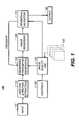
- FIG. 1is a logic flow diagram of an image rendering process according to a predetermined target in one embodiment.
- FIG. 2Ais a block diagram of an image analysis method in one embodiment of the present invention.
- FIG. 2Bshows the result image of feature line extraction from the processing shown in FIG. 2A .
- FIG. 2Cshows the extracted ROIs from the processing of FIG. 2A .
- FIG. 3shows an example of tone scale function generation using image analysis results.
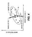
- FIG. 4illustrates image features relative to an image quality aim.
- FIG. 5Ashows an operator interface for obtaining image quality aim parameters.
- FIG. 5Bshows an alternate operator interface for obtaining image quality aim parameters.
- the processing of the present inventionis performed, at least in part, on a computer or other type of control logic processor, such as a dedicated or special-purpose processor, for example, that executes programmed instructions for consistency control.
- a computer or other type of control logic processorsuch as a dedicated or special-purpose processor, for example, that executes programmed instructions for consistency control.
- the computer or other type of control logic processor that is usedis equipped with and in communication with the needed electronic data storage and memory circuitry for executing programmed logic instructions and for storing results.
- the computermay include one or more storage media, for example: magnetic storage media such as magnetic disk or magnetic tape; optical storage media such as optical disk, optical tape, or machine readable bar code or other optical encoding; solid-state electronic data storage devices such as random access memory (RAM) or read-only memory (ROM); or any other physical device or media employed to store computer software having instructions for controlling one or more computers and related data to practice the method according to the present invention.
- magnetic storage mediasuch as magnetic disk or magnetic tape
- optical storage mediasuch as optical disk, optical tape, or machine readable bar code or other optical encoding
- solid-state electronic data storage devicessuch as random access memory (RAM) or read-only memory (ROM); or any other physical device or media employed to store computer software having instructions for controlling one or more computers and related data to practice the method according to the present invention.
- the description in this sectionis directed primarily to chest x-rays in one exemplary embodiment.
- the method of the present inventionis not limited to any one type of radiological image, but can be any of a number of modalities and can be used for imaging other parts of the body as well.
- FIG. 1is a logic flow diagram of an image rendering process 100 according to a predetermined target in one embodiment.
- An input digital image 20can originate from any diagnostic image modality and may be, for example, a computed radiography (CR), digital radiography (DR), computed tomography (CT) or Magnetic Resonance Imaging (MRI) image.
- CRcomputed radiography
- DRdigital radiography
- CTcomputed tomography
- MRIMagnetic Resonance Imaging
- a goal of image rendering process 100is to process the input image so that its appearance satisfies a predetermined image quality preference aim.
- an analysis and feature extraction step 110is first implemented to analyze the properties of input digital image 20 and use the extracted image features to identify and characterize these properties. These obtained properties are then used to direct the generation of rendering parameters.
- the aim that is usedmay be derived from a model that has been set up as a guide to system parameters and performance.
- analysis and feature extraction step 110is expected to provide the image features of the anatomical structures that are of interest as illustrated in FIG. 2A .
- This processincludes three sub-steps.
- a segmentation step 112is performed to detect the body part in the radiographic image. This step can be achieved by any of a number of suitable image segmentation methods known to those skilled in the imaging arts.
- a detection step 114the major anatomical structures inside the skinline of the body part are analyzed and their outlines are detected to provide a rough representation of anatomical structures of the body part.
- chest PAposteroanterior
- an ROI (region of interest) location step 116locates one or more ROIs 30 of the chest image, as shown in FIG. 2C , including diaphragm, mediastinum, apex and lung regions, inside the body part skinline, for example.
- ROIs 30represent major anatomical structures of chest images.
- Feature extraction techniques for obtaining image characteristics or propertiesare familiar to those skilled in the imaging arts and can provide considerable information about the image content. Feature extraction can accurately capture the characteristics or properties of each of the input images and ROIs and provide useful information for subsequent generation of suitable rendering parameters for the image.
- properties that can be computed from the image data and are of particular interest for feature extractioninclude image code value range and statistical data, image contrast, image density, image brightness, latitude, sharpness, regional density, signal-to-noise ratio, contrast-to-noise ratio, image histogram values, image data range, and other computed values that relate to image appearance.
- derived features from the above parameterscan also be extracted from the image data and used to represent other useful image properties or characteristics.
- the parameters typically used to adjust imagessuch as image sharpness, latitudes, brightness, and detail contrast can also be detected using known algorithms and used as image features.
- analysis and feature extraction step 110further provides a frequency band decomposition step 118 , allowing feature extraction and analysis processing to operate on different frequency content, executing on multiple frequency band images.
- frequency band decomposition step 118the image content is de-composed according to multiple frequency bands, in the manner described in the '229 Couwenhoven et al. patent noted earlier.
- Each frequency band imagepresents image characteristics of a certain frequency range. For example, low frequency band image content contains the most information about large size image features, while high frequency band image content corresponds to the detail or fine structure features in the images.
- Feature extraction techniquesobtain characteristics or properties from each frequency band image generated in this decomposition and quantify them, forming feature vectors that can be used to present the image. Depending on rendering preferences, the detected ROIs can be used in the frequency band images to assist local feature extraction. As shown in FIG. 2A , a feature computation step 122 follows, in which one or more properties for each feature or region of interest are computed.
- an electronically stored or derived image quality aim 130provides important information that is first used to help define the overall image rendering process.
- image quality aim 130which may also be termed a preference aim, would use a set of images whose appearances have been manually selected or adjusted by users using operator controls 120 , such as by being prompted for identifying a preferred image rendering from a user interface, for example.
- a particular image quality aim 130may use a library or database that stores multiple instances of image quality aim 130 as shown in FIG. 1 , indexed according to viewer identification, type of image, imaging system, or other criteria.
- image quality aim 130is a distribution of image properties for features generated from a set of one or more images that are known to have aim quality. Using the image feature distribution from a set of aim quality images as representative of the image quality aim can help to more accurately identify desirable image properties. With a database of electronically stored aim quality images, statistical analysis can be used to define image quality aims. For doing this, properties of features from images in the image quality aim database, obtained using any of a number of appropriate image analysis utilities, can provide a distribution of image parameters that are most useful for image quality assessment and validation. For example, a distribution of the image quality aim for chest x-ray characteristics can be generated by studying the full set of chest images that are stored for the image quality aim.
- the analyzed range/distributioncan then be used as the image quality aim in order to direct image rendering parameter generation and evaluation of image rendering results.
- a rendering parameter generation step 140then uses image properties information extracted from the input image in extraction step 110 and data from image quality aim 130 in order to produce parameters suitable for an image rendering step 160 .
- the information about the image and features of the input imagerepresent the specific characteristics or properties of the input image.
- Rendering parameter generation step 140generates a set of parameters for rendering the image in accordance with the image quality aim or the target image.
- the tone scale functionprovides image rendering parameters that transform the image from log exposure to density.
- the tone scale functionadjusts not only the overall image density and dynamic range of the image, but also adjusts image contrast in order to optimize the image display quality of the rendered image in one embodiment.
- rendering parameter generation step 140calculates a tone scale function that enables the transformation of major anatomical structures and other features of the original image into the desired density range specified by the image quality aim.
- rendering a PA view chest x-ray image in conformance with a preferred appearancerequires that the image densities of diaphragm, mediastinum, apex, and lung regions be within certain ranges, as shown in the density/log exposure graph of FIG. 3 .
- the original image log exposure intensities of these regionsare first detected.
- the image intensity ranges and average value of significant anatomy structurescan be readily computed or estimated from ROIs of the structures.
- These average image intensities and ranges, together with an image histogram 40are characteristics or properties of features of the input image usable for rendering parameter generation.
- a mapping procedurethen re-maps these values to a desired range, as shown in the example of FIG. 3 , according to the selected image quality aim 130 .
- a prediction modelcan be generated, using techniques well known in the image analysis arts, by using properties of image features of the input images and the image quality aim to predict a tone scale function.
- Generation of the prediction modelcan be achieved by statistical computation or using machine learning methods, both familiar to those skilled in the image analysis arts.
- machine learning methodseach time a new image is provided, properties related to its image features can be computed.
- the prediction modelis used to predict a tone scale function that is used to process the image so that subsequent rendering satisfies the image quality aim.
- possible rendering parametersinclude other parameters in addition to the tone scale function, such as the global contrast and detail contrast, as described in the Couwenhoven et al. '229 disclosure noted earlier.
- rendering parameters used for manipulating the difference frequency band imagescould be used. These rendering parameters can be derived from both the properties and characteristics of image features and pre-trained parameter models.
- Image rendering step 160uses results from the frequency decomposition operation of frequency band de-composition/manipulation step 118 and parameters generated for rendering in step 140 , as just described.
- the image contentcan now be manipulated according to its frequencies, allowing a number of operations for adjustment to image rendering.
- lower frequency bandsgenerally represent features of large size anatomical structures in the image. Manipulation of lower frequency band data has a pronounced effect on dynamic range or latitude of the image and affects the global appearance of the image.
- Mid-range frequency bandsgenerally represent mid-sized image features. Manipulation of these frequencies has a pronounced effect on image contrast, with little impact on the dynamic range.
- Mid- to high-frequency rangesrepresent smaller features in the image. Manipulation of mid- to high-frequency content affects sharpness or blurring of smaller structure features. The higher frequency ranges represent very fine image detail.
- the image formed in image rendering step 160is evaluated for its conformance to the specified image quality aim 130 .
- Thisis achieved in a rendering validation step 170 .
- rendering validationone or more image quality features are extracted from the rendered image and their properties compared against comparable values in an image quality aim distribution.
- the graph of FIG. 4shows a target distribution 50 as determined by image quality aim 130 .
- target distribution 50is based on two extracted image feature properties; in practice, more than two dimensions may apply, depending on the number of properties of image features selected for image quality evaluation and specified as image quality aim 130 .
- the image property for evaluationmay be, for example, any of contrast, brightness, sharpness, or other characteristic, as described previously.
- properties for two image featuresare extracted from a given rendered image, with at least one property obtained.
- the rendered imageis represented as a point with coordinates (f 1 ,f 2 ) in the two-dimensional image feature space of FIG. 4 . If point (f 1 , f 2 ) lies within the target distribution 50 as depicted for Image 1 in FIG. 4 , the rendered image conforms to the requirement of image quality aim 130 . Therefore, the rendered image achieves the image quality aim requirement and can be output as the final rendering result.
- This looping rendering and validation actioncan be repeated as many times as needed, with different levels of correction applied, until properties of interest for the given features (represented as F 1 and F 2 in the example just described) conform closely enough to the specified image quality aim 130 .
- properties of interest for the given featuresrepresented as F 1 and F 2 in the example just described
- FIG. 4as adjustments from this feedback loop have the intended effect, the corresponding (f 1 , f 2 ) coordinates for the image move closer to or fall within the bounds of target distribution 50 .
- An output rendered imageis provided at output 60 when the aim is met.
- image contrast for the rendered image or region of interestmay be less than satisfactory, the values for this property falling outside of an acceptable range that is specified in the selected image quality aim 130 .
- a variable parameter generated by rendering parameter generation step 140 and used by the rendering algorithm for image rendering step 160can be appropriately increased or decreased and rendering step 160 executed once again for the image or ROI within the image.
- the next execution of rendering validation step 170may indicate that the rendered image now exhibits acceptable contrast and conforms to image quality aim 130 .
- the next execution of rendering validation step 170may indicate that the resulting change in contrast does not provide sufficient improvement, or there may even be a reduction in the measured contrast. Correction can then be applied by rendering parameter generation step 140 , followed by another iteration of rendering and validation.
- this examplecan be expanded to encompass multiple image features and their properties. It can also be appreciated that there can be added complexity in cases wherein changes to rendering parameters may improve performance with respect to some properties for specific features, but have unintended effects for other features. For example, increasing the dynamic range may also have the unintended effect of increasing the signal-to-noise ratio for an image.
- the feedback loopexits rendering validation step 170 if acceptable quality is not measured after a fixed number of iterations.
- image quality aim 130typically obtained from some type of image processing model, is first used as one factor that helps to condition how rendering parameters are generated in step 140 . Then, following rendering, image quality aim 130 is used for measurement, providing one or more parameters against which image rendering can be validated.
- an adaptive systemthat limits the number of feedback loop iterations that are used during image processing. For example, if two or more processing iterations are regularly needed for processing a large percentage of the acquired images, processing efficiency can be improved by updating the prediction model and its generated image processing parameters or other data used to determine how the image is processed.
- Embodiments of the present inventionmonitor the relative frequency of feedback loop iterations and respond to excessive processing by analyzing information relevant to errors and adjusting various image processing parameters accordingly. The adjusted parameters can themselves be tested in order to further refine how images are processed and to reduce the number of images requiring multiple rendering processes.
- embodiments of the present inventionset a maximum feedback loop number. Once an image reaches the maximal number, its rendered image is outputted as the final result, along with an alert that indicates reaching the maximal feedback loop number.
- Such an alertcan be displayed for the technologist to review, and can give the technologist the opportunity to correct any capture condition or parameters in order to improve the retake image quality.
- the technologistmay want to change one or more technique settings, such as the kVp or mAs settings, or use an appropriate grid to improve the image quality.
- An alertmay also indicate the need for system calibration or other procedure.
- a measure of consistencycan thus be obtained in rendering diagnostic images.
- the relative degree of consistency that can be achievedis based, at least in part, on the setup of image quality aim 130 .
- parameters of image quality aim 130effectively determine the size and shape of target distribution 50 and thus the amount of difference that is allowed between values of properties for identified features.
- output 60includes a message for informing the user, displayed on an operator console for example, or a data record provided in some form that indicates failure of the rendering control loop to provide a suitable rendered output image for some reason.
- output 60provides information to a networked Quality Assurance (QA) system for assessment of a performance problem or other problem related to the imaging process.
- QAQuality Assurance
- the processmay directly prompt the viewer to review results of feedback loop execution in order to obtain approval or to adjust parameters accordingly.
- the phrase “feedback loop” as used hereinis a term of art generally used in digital processing to describe a looping operation that repeats one or more procedures based on assessing “feedback” or results data from previous processing. This distinguishes a feedback loop operation from a looping process that simply increments a counter to repeat an operation a fixed number of times, for example.
- the feedback loop of the present inventioncan be constrained to operate no more than a fixed number of times, as tracked by the extra step of incrementing and checking a counter, for example, not specifically shown in the basic flow diagram of FIG. 1 .
- An image quality aim 130that is suited to a particular radiologist, to a specified image type, or for a designated imaging apparatus, hospital, or other entity, can be set up in a number of ways.
- a benchmark image 26is provided on a display screen 32 .
- the viewerthen enters suitable image quality parameters using a set of controls 34 , or using some other entry mechanism.
- Softwareallows the viewer to generate, edit, and save one or more image quality aims suitable for a specific image type or feature by viewing and making changes to the appearance of the corresponding benchmark image.
- the softwareanalyzes the benchmark image when saved by the viewer and extracts the needed information as to suitable image characteristics.
- a number of user interface utilitiescan be used in order to obtain viewer entries and selections, including graphical user interface (GUI) tools that use a touchscreen or use a mouse or other pointer, for example.
- GUIgraphical user interface
- these same procedurescould be used for setting up image quality aims 130 ( FIG. 1 ) for a full benchmark image 26 or for one or more regions of interest (ROI) 36 within the benchmark image.
- ROIregions of interest
- a touchscreen or other pointer entrycan be used to specify ROI 36 and to electronically save settings of controls 34 specifically for this particular type of ROI within the chest x-ray or other type of image.
- This same type of sequencecan be used where there are multiple ROIs or other features, allowing individual parameter settings and corresponding image quality aim 130 for each of a set of multiple ROIs within an image.
- FIG. 5Bshows an alternate user interface arrangement in which a set of thumbnail images 42 appear, each image having different appearance due to different rendering parameter settings.
- detailis increased moving up the screen, dynamic range is increased in moving across from left to right.
- the viewer selectionis then saved and used to set up the corresponding image quality aim 130 ( FIG. 1 ).
- softwareis provided to analyze the particular image selected by the viewer and to extract the needed information as to suitable image quality characteristics.
- Multiple image quality aims 130can also be obtained and stored from a user interface display in this manner.
- a series of benchmark imagesare used as a training set and one or more skilled viewers are presented with the different images in the training set in order to grade or score them for suitability.
- Neural network or other adaptive logic for “learning” viewer responsesis then trained according to rendering characteristics that are judged most suitable by the expert viewers.
- the softwareanalyzes user scoring and preferences and determines what quality metrics apply for each image type. For example, automated image processing tools can detect image contrast or other characteristics. Over time, additional data points can be gathered, improving the statistical accuracy available for obtaining suitable properties for the various image features.
- image quality aims 130are obtained from statistical data computed from a given set of multiple images, without the need for specific expert observer evaluation of each individual image.
- the PA chest x-rayis one type of image that is particularly rich in the type of information it can provide and can be used for diagnosis of a number of different conditions.
- Radiologist Aprefers image sharpness and a high level of detail contrast for chest x-ray images for viewing lung fields.
- Radiologist Bwith a slightly different purpose, prefers a very broad dynamic range for the same type of image.
- the same stored image quality aim 130is not likely to satisfy both radiologists.
- a first image quality aimis set up and electronically stored for use by radiologist A, providing heightened contrast over the lung field ROI.
- An alternate image quality aim with a broadened dynamic range over denser (darker) areas of the ROIis set up and stored for use by radiologist B.
- the image rendering process of FIG. 1is carried out for each image quality aim 130 , with feedback based upon validation of the rendering process as described earlier.
- Rendering an imagecan be highly complex, involving a number of variables, with results and acceptability to an individual viewer difficult to predict. This problem is further complicated because of variables such as imaging system differences; patient size, age, gender, and positioning; technologist training and performance; and other characteristics that affect the overall image quality and appearance of the obtained x-ray.
- the feedback loop of the present inventionprovides an automated way to validate that specific parameters or ranges of values have been applied and, where needed, to readjust rendering parameters and repeat the rendering process when rendered results fall outside of an acceptable range with respect to one or more particular image features and their attributes.
- image quality aimsthe image can be rendered, analyzed, and checked against those aims to determine whether or not the image is rendered appropriately. This method can be used for the complete image as well as for one or more regions of interest or individual features within the image.
- Supplementary information that relates to technologist, equipment, or departmental performancecan also be extracted from the image quality validation process. Such information can be used in conjunction with various image metadata in order to provide statistical data that may help administrators to determine training needs, maintenance or calibration requirements, or other needed support functions.
- image processing toolswith a control loop to assess and correct image rendering, in order to provide more usable and accurate diagnostic imaging.
- the processing performed for the present inventionis executed at a computer or other type of processor or may be executed over a network using more than a single processor.
- image quality aimsmay be set up and stored at different locations along a network and may be addressed and accessible by a separate processor that executes the basic image processing function.
- image rendering and image displayare also processor-intensive operations, making particular demands on computer processing power where the display is a high-resolution display, such as that used in the diagnostic imaging environment.
Landscapes
- Engineering & Computer Science (AREA)
- Computer Vision & Pattern Recognition (AREA)
- Physics & Mathematics (AREA)
- General Physics & Mathematics (AREA)
- Theoretical Computer Science (AREA)
- Quality & Reliability (AREA)
- Apparatus For Radiation Diagnosis (AREA)
- Image Processing (AREA)
Abstract
Description
- A preference range of the diaphragm region in chest images is within [1500, 2000].
- A preference range of the mediastrinum region in chest images is within [1100, 1300].
- A preference range of the apex and shoulder regions in chest images is within [800, 1000].
- A preference range of lung fields in chest images is within [500, 750].
- 20. Image
- 24. Spine midline
- 26. Benchmark image
- 28. Lung centerline
- 30. ROI
- 32. Display screen
- 34. Control
- 36. Region of interest
- 40. Histogram
- 42. Set of thumbnail images
- 50. Target distribution
- 60. Output
- 100. Image rendering process
- 110. Analysis and feature extraction step
- 112. Segmentation step
- 114. Detection step
- 116. ROI location step
- 118. Frequency band decomposition step
- 120. Operator control
- 122. Feature computation step
- 130. Image quality aim
- 140. Rendering parameter generation step
- 160. Image rendering step
- 170. Rendering validation step
- F1, F1′, F1″,F2. Feature
- ΔF1′,ΔF1″ Difference
Claims (20)
Priority Applications (1)
| Application Number | Priority Date | Filing Date | Title |
|---|---|---|---|
| US12/485,072US8270695B2 (en) | 2008-10-07 | 2009-06-16 | Diagnostic image processing with automatic self image quality validation |
Applications Claiming Priority (2)
| Application Number | Priority Date | Filing Date | Title |
|---|---|---|---|
| US10333808P | 2008-10-07 | 2008-10-07 | |
| US12/485,072US8270695B2 (en) | 2008-10-07 | 2009-06-16 | Diagnostic image processing with automatic self image quality validation |
Publications (2)
| Publication Number | Publication Date |
|---|---|
| US20100086182A1 US20100086182A1 (en) | 2010-04-08 |
| US8270695B2true US8270695B2 (en) | 2012-09-18 |
Family
ID=42075858
Family Applications (2)
| Application Number | Title | Priority Date | Filing Date |
|---|---|---|---|
| US12/485,072Active2031-07-02US8270695B2 (en) | 2008-10-07 | 2009-06-16 | Diagnostic image processing with automatic self image quality validation |
| US12/486,230Active2032-02-01US8571290B2 (en) | 2007-08-06 | 2009-06-17 | Automated quantification of digital radiographic image quality |
Family Applications After (1)
| Application Number | Title | Priority Date | Filing Date |
|---|---|---|---|
| US12/486,230Active2032-02-01US8571290B2 (en) | 2007-08-06 | 2009-06-17 | Automated quantification of digital radiographic image quality |
Country Status (1)
| Country | Link |
|---|---|
| US (2) | US8270695B2 (en) |
Cited By (5)
| Publication number | Priority date | Publication date | Assignee | Title |
|---|---|---|---|---|
| US20100086189A1 (en)* | 2008-10-07 | 2010-04-08 | Xiaohui Wang | Automated quantification of digital radiographic image quality |
| US20120010495A1 (en)* | 2010-07-07 | 2012-01-12 | Siemens Aktiengesellschaft | Method For Generating MR Images And An Appropriately Designed Magnetic Resonance System |
| US20150286780A1 (en)* | 2014-04-08 | 2015-10-08 | Siemens Medical Solutions Usa, Inc. | Imaging Protocol Optimization With Consensus Of The Community |
| US9928592B2 (en) | 2016-03-14 | 2018-03-27 | Sensors Unlimited, Inc. | Image-based signal detection for object metrology |
| US10007971B2 (en) | 2016-03-14 | 2018-06-26 | Sensors Unlimited, Inc. | Systems and methods for user machine interaction for image-based metrology |
Families Citing this family (55)
| Publication number | Priority date | Publication date | Assignee | Title |
|---|---|---|---|---|
| US7787672B2 (en) | 2004-11-04 | 2010-08-31 | Dr Systems, Inc. | Systems and methods for matching, naming, and displaying medical images |
| US7970625B2 (en) | 2004-11-04 | 2011-06-28 | Dr Systems, Inc. | Systems and methods for retrieval of medical data |
| US7920152B2 (en) | 2004-11-04 | 2011-04-05 | Dr Systems, Inc. | Systems and methods for viewing medical 3D imaging volumes |
| US7660488B2 (en) | 2004-11-04 | 2010-02-09 | Dr Systems, Inc. | Systems and methods for viewing medical images |
| US7885440B2 (en) | 2004-11-04 | 2011-02-08 | Dr Systems, Inc. | Systems and methods for interleaving series of medical images |
| US7953614B1 (en) | 2006-11-22 | 2011-05-31 | Dr Systems, Inc. | Smart placement rules |
| EP2283463B1 (en)* | 2008-05-30 | 2014-10-29 | GE Healthcare Bio-Sciences Corp. | System and method for detecting and eliminating one or more defocused or low contrast-to-noise ratio images |
| US8402066B2 (en) | 2008-10-07 | 2013-03-19 | Gemological Institute Of America (Gia) | Method and system for providing a clarity grade for a gem |
| US8380533B2 (en) | 2008-11-19 | 2013-02-19 | DR Systems Inc. | System and method of providing dynamic and customizable medical examination forms |
| US8478012B2 (en)* | 2009-09-14 | 2013-07-02 | General Electric Company | Methods, apparatus and articles of manufacture to process cardiac images to detect heart motion abnormalities |
| US8712120B1 (en) | 2009-09-28 | 2014-04-29 | Dr Systems, Inc. | Rules-based approach to transferring and/or viewing medical images |
| JP5416845B2 (en)* | 2010-10-13 | 2014-02-12 | 株式会社日立製作所 | Medical image display device, medical information management server |
| JP5868119B2 (en)* | 2010-12-09 | 2016-02-24 | キヤノン株式会社 | Image processing apparatus, radiation imaging system, image processing method, and recording medium |
| CN103261878B (en)* | 2010-12-13 | 2016-03-30 | 皇家飞利浦电子股份有限公司 | Method and apparatus for analyzing a region of interest in an object using X-rays |
| US20140140595A1 (en)* | 2011-06-30 | 2014-05-22 | Ge Healthcare Bio-Sciences Corp. | Microscopy system and method for biological imaging |
| WO2013002720A1 (en)* | 2011-06-30 | 2013-01-03 | Ge Healthcare Bio-Sciences Corp | Image quality optimization of biological imaging |
| US9075899B1 (en) | 2011-08-11 | 2015-07-07 | D.R. Systems, Inc. | Automated display settings for categories of items |
| CN103020947B (en) | 2011-09-23 | 2016-04-06 | 阿里巴巴集团控股有限公司 | A kind of mass analysis method of image and device |
| US9117289B2 (en)* | 2011-11-11 | 2015-08-25 | Konica Minolta, Inc. | Medical imaging system, medical image processing apparatus, and computer-readable medium |
| DE102011090047A1 (en)* | 2011-12-28 | 2013-07-25 | Klinikum der Universität München - Campus Innenstadt | Control procedure and control system |
| US9741098B2 (en)* | 2012-10-12 | 2017-08-22 | Nvidia Corporation | System and method for optimizing image quality in a digital camera |
| US9495604B1 (en) | 2013-01-09 | 2016-11-15 | D.R. Systems, Inc. | Intelligent management of computerized advanced processing |
| US8824752B1 (en)* | 2013-03-15 | 2014-09-02 | Heartflow, Inc. | Methods and systems for assessing image quality in modeling of patient anatomic or blood flow characteristics |
| US10395350B2 (en)* | 2013-07-26 | 2019-08-27 | Li-Cor, Inc. | Adaptive background detection and signal quantification systems and methods |
| US10025479B2 (en)* | 2013-09-25 | 2018-07-17 | Terarecon, Inc. | Advanced medical image processing wizard |
| DE102013221949B4 (en)* | 2013-10-29 | 2019-03-28 | Siemens Healthcare Gmbh | Method for displaying medical image data |
| US9152761B2 (en) | 2014-01-10 | 2015-10-06 | Heartflow, Inc. | Systems and methods for identifying medical image acquisition parameters |
| US9754082B2 (en) | 2014-05-30 | 2017-09-05 | Heartflow, Inc. | Systems and methods for reporting blood flow characteristics |
| CN106688014B (en)* | 2014-10-30 | 2018-04-24 | 皇家飞利浦有限公司 | Apparatus and method for the picture quality for determining radiographic image |
| US20170046483A1 (en) | 2015-04-30 | 2017-02-16 | D.R. Systems, Inc. | Database systems and interactive user interfaces for dynamic interaction with, and comparison of, digital medical image data |
| US9706112B2 (en)* | 2015-09-02 | 2017-07-11 | Mediatek Inc. | Image tuning in photographic system |
| US9916525B2 (en)* | 2015-10-13 | 2018-03-13 | Siemens Healthcare Gmbh | Learning-based framework for personalized image quality evaluation and optimization |
| EP3169069A1 (en)* | 2015-11-10 | 2017-05-17 | FEI Company | Systems and methods for imaging device interfaces |
| US10984528B2 (en) | 2016-07-19 | 2021-04-20 | Volpara Health Technologies Limited | System and apparatus for clinical decision optimisation |
| EP3545523B1 (en)* | 2016-11-23 | 2023-10-18 | Koninklijke Philips N.V. | A closed-loop system for contextually-aware image-quality collection and feedback |
| KR101929412B1 (en) | 2017-02-28 | 2018-12-14 | 연세대학교 산학협력단 | Image database-based real-time registration method of 2d x-ray image and 3d ct image, and an apparatus thereof |
| US10977509B2 (en) | 2017-03-27 | 2021-04-13 | Samsung Electronics Co., Ltd. | Image processing method and apparatus for object detection |
| CN108664840A (en)* | 2017-03-27 | 2018-10-16 | 北京三星通信技术研究有限公司 | Image-recognizing method and device |
| US10467507B1 (en)* | 2017-04-19 | 2019-11-05 | Amazon Technologies, Inc. | Image quality scoring |
| EP3417781A1 (en)* | 2017-06-23 | 2018-12-26 | Koninklijke Philips N.V. | Method and system for image analysis of a medical image |
| WO2019092575A1 (en)* | 2017-11-07 | 2019-05-16 | Volpara Health Technologies Limited | System and method for quantification of tissue over time |
| EP3503528B1 (en) | 2017-12-21 | 2020-10-07 | Axis AB | Determination of a contrast value for a digital image |
| JP6881611B2 (en)* | 2018-01-09 | 2021-06-02 | 株式会社島津製作所 | Image creation device and trained model generation method |
| CN108921191B (en)* | 2018-05-25 | 2021-10-26 | 北方工业大学 | Multi-biological-feature fusion recognition method based on image quality evaluation |
| BR102018071293A2 (en)* | 2018-10-16 | 2020-04-28 | Soc Beneficente Israelita Brasileira Hospital Albert Einstein | method for automating resolution testing on digital images |
| CA3120480A1 (en) | 2018-11-24 | 2020-05-28 | Densitas Incorporated | System and method for assessing medical images |
| TWI741429B (en)* | 2019-12-04 | 2021-10-01 | 晶睿通訊股份有限公司 | Image analyzing method of increasing analysis accuracy and related image monitoring apparatus |
| WO2021141681A1 (en)* | 2020-01-10 | 2021-07-15 | Carestream Health, Inc. | Method amd system to predict prognosis for critically ill patients |
| CN113610744A (en)* | 2020-04-20 | 2021-11-05 | 锐珂(上海)医疗器材有限公司 | X-ray image quality control system |
| EP3910644A1 (en)* | 2020-05-12 | 2021-11-17 | Koninklijke Philips N.V. | Quality control in medical imaging |
| EP3923293A1 (en)* | 2020-06-09 | 2021-12-15 | Koninklijke Philips N.V. | System and method for analysis of medical image data based on an interaction of quality metrics |
| CN114359129B (en)* | 2020-10-13 | 2025-07-01 | 深圳迈瑞生物医疗电子股份有限公司 | DR image analysis method and electronic device |
| EP4134972A1 (en)* | 2021-08-13 | 2023-02-15 | Koninklijke Philips N.V. | Machine learning based quality assessment of medical imagery and its use in facilitating imaging operations |
| EP4145457A1 (en) | 2021-09-07 | 2023-03-08 | Siemens Healthcare GmbH | Method and system for image-based operational decision support |
| US20240105325A1 (en)* | 2022-09-26 | 2024-03-28 | Jay Harary | Remote rescue |
Citations (12)
| Publication number | Priority date | Publication date | Assignee | Title |
|---|---|---|---|---|
| US6370277B1 (en) | 1998-12-07 | 2002-04-09 | Kofax Image Products, Inc. | Virtual rescanning: a method for interactive document image quality enhancement |
| US20050063575A1 (en)* | 2003-09-22 | 2005-03-24 | Ge Medical Systems Global Technology, Llc | System and method for enabling a software developer to introduce informational attributes for selective inclusion within image headers for medical imaging apparatus applications |
| US20050256743A1 (en) | 2004-05-11 | 2005-11-17 | Dale Richard B | Medical imaging-quality assessment and improvement system (QAISys) |
| US20060095429A1 (en) | 2004-10-29 | 2006-05-04 | Eastman Kodak Company | Networked system for routing medical images |
| US20060155579A1 (en)* | 2005-01-07 | 2006-07-13 | Frank Reid | Medical image viewing management and status system |
| US7266229B2 (en) | 2003-07-24 | 2007-09-04 | Carestream Health, Inc. | Method for rendering digital radiographic images for display based on independent control of fundamental image quality parameters |
| US7321674B2 (en) | 2002-02-22 | 2008-01-22 | Agfa Healthcare, N.V. | Method of normalising a digital signal representation of an image |
| JP2008076616A (en) | 2006-09-20 | 2008-04-03 | Konica Minolta Business Technologies Inc | Image forming apparatus, its manufacturing method, its maintenance method, and its intermediate transfer member |
| US20080118139A1 (en) | 2006-11-22 | 2008-05-22 | Zhimin Huo | Roi-based rendering for diagnostic image consistency |
| US7386155B2 (en) | 2004-11-22 | 2008-06-10 | Carestream Health, Inc. | Transforming visual preference terminology for radiographic images |
| US7466323B2 (en)* | 2003-06-03 | 2008-12-16 | Ge Medical Systems Information Technologies, Inc. | Key image note display and annotation system and method |
| US8051386B2 (en)* | 2006-12-21 | 2011-11-01 | Sectra Ab | CAD-based navigation of views of medical image data stacks or volumes |
Family Cites Families (17)
| Publication number | Priority date | Publication date | Assignee | Title |
|---|---|---|---|---|
| US6775399B1 (en)* | 1999-11-17 | 2004-08-10 | Analogic Corporation | ROI segmentation image processing system |
| GB0314162D0 (en)* | 2003-06-18 | 2003-07-23 | British Telecomm | Edge analysis in video quality assessment |
| US7394925B2 (en)* | 2003-06-18 | 2008-07-01 | Canon Kabushiki Kaisha | Radiography apparatus and radiography method |
| US7512286B2 (en)* | 2003-10-27 | 2009-03-31 | Hewlett-Packard Development Company, L.P. | Assessing image quality |
| US7090640B2 (en)* | 2003-11-12 | 2006-08-15 | Q-Vision | System and method for automatic determination of a region of interest within an image |
| US7672491B2 (en)* | 2004-03-23 | 2010-03-02 | Siemens Medical Solutions Usa, Inc. | Systems and methods providing automated decision support and medical imaging |
| WO2006046228A1 (en)* | 2004-10-26 | 2006-05-04 | Moshe Keydar | Systems and methods for simultaneous and automatic digital images processing |
| DE102004060127B4 (en)* | 2004-12-13 | 2007-05-24 | Siemens Ag | X-ray diagnostic device and method for operating an X-ray diagnostic device for determining the image quality of the X-ray diagnostic device or the visibility of clinically relevant objects determining values |
| EP1878239A2 (en)* | 2005-04-28 | 2008-01-16 | Bruce Reiner | Method and apparatus for automated quality assurance in medical imaging |
| US7532942B2 (en)* | 2006-01-30 | 2009-05-12 | Bruce Reiner | Method and apparatus for generating a technologist quality assurance scorecard |
| US8184874B2 (en)* | 2006-12-22 | 2012-05-22 | Carestream Health, Inc. | Enhanced display of medical images |
| WO2008115410A2 (en)* | 2007-03-16 | 2008-09-25 | Sti Medical Systems, Llc | A method to provide automated quality feedback to imaging devices to achieve standardized imaging data |
| US7860286B2 (en)* | 2007-04-24 | 2010-12-28 | Microsoft Corporation | Medical image acquisition error detection |
| US8086007B2 (en)* | 2007-10-18 | 2011-12-27 | Siemens Aktiengesellschaft | Method and system for human vision model guided medical image quality assessment |
| US8275201B2 (en)* | 2008-03-06 | 2012-09-25 | Tyco Healthcare Group Lp | Image enhancement and application functionality for medical and other uses |
| US8203340B2 (en)* | 2008-08-11 | 2012-06-19 | Siemens Medical Solutions Usa, Inc. | Magnetic resonance method and apparatus for generating a perfusion image |
| US8270695B2 (en)* | 2008-10-07 | 2012-09-18 | Carestream Health, Inc. | Diagnostic image processing with automatic self image quality validation |
- 2009
- 2009-06-16USUS12/485,072patent/US8270695B2/enactiveActive
- 2009-06-17USUS12/486,230patent/US8571290B2/enactiveActive
Patent Citations (12)
| Publication number | Priority date | Publication date | Assignee | Title |
|---|---|---|---|---|
| US6370277B1 (en) | 1998-12-07 | 2002-04-09 | Kofax Image Products, Inc. | Virtual rescanning: a method for interactive document image quality enhancement |
| US7321674B2 (en) | 2002-02-22 | 2008-01-22 | Agfa Healthcare, N.V. | Method of normalising a digital signal representation of an image |
| US7466323B2 (en)* | 2003-06-03 | 2008-12-16 | Ge Medical Systems Information Technologies, Inc. | Key image note display and annotation system and method |
| US7266229B2 (en) | 2003-07-24 | 2007-09-04 | Carestream Health, Inc. | Method for rendering digital radiographic images for display based on independent control of fundamental image quality parameters |
| US20050063575A1 (en)* | 2003-09-22 | 2005-03-24 | Ge Medical Systems Global Technology, Llc | System and method for enabling a software developer to introduce informational attributes for selective inclusion within image headers for medical imaging apparatus applications |
| US20050256743A1 (en) | 2004-05-11 | 2005-11-17 | Dale Richard B | Medical imaging-quality assessment and improvement system (QAISys) |
| US20060095429A1 (en) | 2004-10-29 | 2006-05-04 | Eastman Kodak Company | Networked system for routing medical images |
| US7386155B2 (en) | 2004-11-22 | 2008-06-10 | Carestream Health, Inc. | Transforming visual preference terminology for radiographic images |
| US20060155579A1 (en)* | 2005-01-07 | 2006-07-13 | Frank Reid | Medical image viewing management and status system |
| JP2008076616A (en) | 2006-09-20 | 2008-04-03 | Konica Minolta Business Technologies Inc | Image forming apparatus, its manufacturing method, its maintenance method, and its intermediate transfer member |
| US20080118139A1 (en) | 2006-11-22 | 2008-05-22 | Zhimin Huo | Roi-based rendering for diagnostic image consistency |
| US8051386B2 (en)* | 2006-12-21 | 2011-11-01 | Sectra Ab | CAD-based navigation of views of medical image data stacks or volumes |
Cited By (7)
| Publication number | Priority date | Publication date | Assignee | Title |
|---|---|---|---|---|
| US20100086189A1 (en)* | 2008-10-07 | 2010-04-08 | Xiaohui Wang | Automated quantification of digital radiographic image quality |
| US8571290B2 (en) | 2008-10-07 | 2013-10-29 | Carestream Health, Inc. | Automated quantification of digital radiographic image quality |
| US20120010495A1 (en)* | 2010-07-07 | 2012-01-12 | Siemens Aktiengesellschaft | Method For Generating MR Images And An Appropriately Designed Magnetic Resonance System |
| US8988074B2 (en)* | 2010-07-07 | 2015-03-24 | Siemens Aktiengesellschaft | Method for generating MR images and correspondingly embodied magnetic resonance scanner |
| US20150286780A1 (en)* | 2014-04-08 | 2015-10-08 | Siemens Medical Solutions Usa, Inc. | Imaging Protocol Optimization With Consensus Of The Community |
| US9928592B2 (en) | 2016-03-14 | 2018-03-27 | Sensors Unlimited, Inc. | Image-based signal detection for object metrology |
| US10007971B2 (en) | 2016-03-14 | 2018-06-26 | Sensors Unlimited, Inc. | Systems and methods for user machine interaction for image-based metrology |
Also Published As
| Publication number | Publication date |
|---|---|
| US20100086189A1 (en) | 2010-04-08 |
| US8571290B2 (en) | 2013-10-29 |
| US20100086182A1 (en) | 2010-04-08 |
Similar Documents
| Publication | Publication Date | Title |
|---|---|---|
| US8270695B2 (en) | Diagnostic image processing with automatic self image quality validation | |
| US11615508B2 (en) | Systems and methods for consistent presentation of medical images using deep neural networks | |
| US8238630B2 (en) | Image processing apparatus and program for the same | |
| CN107464231B (en) | System and method for determining optimal operating parameters for medical imaging | |
| US8150110B2 (en) | ROI-based rendering for diagnostic image consistency | |
| US9536316B2 (en) | Apparatus and method for lesion segmentation and detection in medical images | |
| US20210012488A1 (en) | Automated scan quality monitoring system | |
| US11779288B2 (en) | Methods, systems, and apparatus for determining radiation doses | |
| EP4022562B1 (en) | Image processing for stroke characterization | |
| KR20150073628A (en) | System and method for adapting diagnosis model of computer aided diagnosis | |
| CN111242947A (en) | CT scanning image quality evaluation method, computer readable storage medium and CT scanning device | |
| US7697739B2 (en) | Method, apparatus and program for image processing, and abnormal shadow detection | |
| CN118675683A (en) | Quality control and retrieval system for digital images and reports | |
| US8965070B2 (en) | Interactive computer-aided diagnosis | |
| US20240169537A1 (en) | Methods and systems for automatic ct image quality assessment | |
| US20250209626A1 (en) | Methods and systems for automatic ct image quality assessment | |
| US20240120072A1 (en) | System and method for obtaining quality image data and measurements from a medical imaging device | |
| EP4599771A1 (en) | Defining imaging parameters of a medical imaging system | |
| Hoye | Truth-based Radiomics for Prediction of Lung Cancer Prognosis | |
| JP2025518611A (en) | Compensating for differences in medical images | |
| CN117094939A (en) | Automatic quantitative evaluation method for medical image quality based on clinical application targets | |
| CN116258661A (en) | DR image analysis method, DR imaging device and electronic device | |
| CN114271837A (en) | Image diagnosis support device and image processing method | |
| CN114341934A (en) | Confidence Maps for Radiographic Image Optimization |
Legal Events
| Date | Code | Title | Description |
|---|---|---|---|
| AS | Assignment | Owner name:CARESTREAM HEALTH, INC.,NEW YORK Free format text:ASSIGNMENT OF ASSIGNORS INTEREST;ASSIGNORS:LUO, HUI;WANG, XIAOHUI;COUWENHOVEN, MARY E.;SIGNING DATES FROM 20090710 TO 20090803;REEL/FRAME:023101/0159 Owner name:CARESTREAM HEALTH, INC., NEW YORK Free format text:ASSIGNMENT OF ASSIGNORS INTEREST;ASSIGNORS:LUO, HUI;WANG, XIAOHUI;COUWENHOVEN, MARY E.;SIGNING DATES FROM 20090710 TO 20090803;REEL/FRAME:023101/0159 | |
| AS | Assignment | Owner name:CREDIT SUISSE AG, CAYMAN ISLANDS BRANCH, NEW YORK Free format text:INTELLECTUAL PROPERTY SECURITY AGREEMENT;ASSIGNORS:CARESTREAM HEALTH, INC.;CARESTREAM DENTAL, LLC;QUANTUM MEDICAL IMAGING, L.L.C.;AND OTHERS;REEL/FRAME:026269/0411 Effective date:20110225 | |
| FEPP | Fee payment procedure | Free format text:PAYOR NUMBER ASSIGNED (ORIGINAL EVENT CODE: ASPN); ENTITY STATUS OF PATENT OWNER: LARGE ENTITY | |
| AS | Assignment | Owner name:CARESTREAM HEALTH, INC., NEW YORK Free format text:RELEASE OF SECURITY INTEREST IN INTELLECTUAL PROPERTY (SECOND LIEN);ASSIGNOR:CREDIT SUISSE AG, CAYMAN ISLANDS BRANCH;REEL/FRAME:027851/0812 Effective date:20110225 | |
| STCF | Information on status: patent grant | Free format text:PATENTED CASE | |
| AS | Assignment | Owner name:CREDIT SUISSE AG, CAYMAN ISLANDS BRANCH, NEW YORK Free format text:AMENDED AND RESTATED INTELLECTUAL PROPERTY SECURITY AGREEMENT (FIRST LIEN);ASSIGNORS:CARESTREAM HEALTH, INC.;CARESTREAM DENTAL LLC;QUANTUM MEDICAL IMAGING, L.L.C.;AND OTHERS;REEL/FRAME:030711/0648 Effective date:20130607 | |
| AS | Assignment | Owner name:CREDIT SUISSE AG, CAYMAN ISLANDS BRANCH, NEW YORK Free format text:SECOND LIEN INTELLECTUAL PROPERTY SECURITY AGREEMENT;ASSIGNORS:CARESTREAM HEALTH, INC.;CARESTREAM DENTAL LLC;QUANTUM MEDICAL IMAGING, L.L.C.;AND OTHERS;REEL/FRAME:030724/0154 Effective date:20130607 | |
| FPAY | Fee payment | Year of fee payment:4 | |
| MAFP | Maintenance fee payment | Free format text:PAYMENT OF MAINTENANCE FEE, 8TH YEAR, LARGE ENTITY (ORIGINAL EVENT CODE: M1552); ENTITY STATUS OF PATENT OWNER: LARGE ENTITY Year of fee payment:8 | |
| AS | Assignment | Owner name:JPMORGAN CHASE BANK, N.A., ILLINOIS Free format text:GRANT OF SECURITY INTEREST IN PATENT RIGHTS - TL;ASSIGNOR:CARESTREAM HEALTH, INC.;REEL/FRAME:061579/0341 Effective date:20220930 Owner name:JPMORGAN CHASE BANK, N.A., ILLINOIS Free format text:GRANT OF SECURITY INTEREST IN PATENT RIGHTS - ABL;ASSIGNOR:CARESTREAM HEALTH, INC.;REEL/FRAME:061579/0301 Effective date:20220930 | |
| AS | Assignment | Owner name:TROPHY DENTAL INC., GEORGIA Free format text:RELEASE BY SECURED PARTY;ASSIGNOR:CREDIT SUISSE AG, CAYMAN ISLANDS BRANCH;REEL/FRAME:061681/0380 Effective date:20220930 Owner name:QUANTUM MEDICAL HOLDINGS, LLC, NEW YORK Free format text:RELEASE BY SECURED PARTY;ASSIGNOR:CREDIT SUISSE AG, CAYMAN ISLANDS BRANCH;REEL/FRAME:061681/0380 Effective date:20220930 Owner name:QUANTUM MEDICAL IMAGING, L.L.C., NEW YORK Free format text:RELEASE BY SECURED PARTY;ASSIGNOR:CREDIT SUISSE AG, CAYMAN ISLANDS BRANCH;REEL/FRAME:061681/0380 Effective date:20220930 Owner name:CARESTREAM DENTAL, LLC, GEORGIA Free format text:RELEASE BY SECURED PARTY;ASSIGNOR:CREDIT SUISSE AG, CAYMAN ISLANDS BRANCH;REEL/FRAME:061681/0380 Effective date:20220930 Owner name:CARESTREAM HEALTH, INC., NEW YORK Free format text:RELEASE BY SECURED PARTY;ASSIGNOR:CREDIT SUISSE AG, CAYMAN ISLANDS BRANCH;REEL/FRAME:061681/0380 Effective date:20220930 Owner name:TROPHY DENTAL INC., GEORGIA Free format text:RELEASE OF SECURITY INTEREST IN INTELLECTUAL PROPERTY (SECOND LIEN);ASSIGNOR:CREDIT SUISSE AG, CAYMAN ISLANDS BRANCH;REEL/FRAME:061683/0601 Effective date:20220930 Owner name:QUANTUM MEDICAL IMAGING, L.L.C., NEW YORK Free format text:RELEASE OF SECURITY INTEREST IN INTELLECTUAL PROPERTY (SECOND LIEN);ASSIGNOR:CREDIT SUISSE AG, CAYMAN ISLANDS BRANCH;REEL/FRAME:061683/0601 Effective date:20220930 Owner name:CARESTREAM DENTAL LLC, GEORGIA Free format text:RELEASE OF SECURITY INTEREST IN INTELLECTUAL PROPERTY (SECOND LIEN);ASSIGNOR:CREDIT SUISSE AG, CAYMAN ISLANDS BRANCH;REEL/FRAME:061683/0601 Effective date:20220930 Owner name:CARESTREAM HEALTH, INC., NEW YORK Free format text:RELEASE OF SECURITY INTEREST IN INTELLECTUAL PROPERTY (SECOND LIEN);ASSIGNOR:CREDIT SUISSE AG, CAYMAN ISLANDS BRANCH;REEL/FRAME:061683/0601 Effective date:20220930 Owner name:TROPHY DENTAL INC., NEW YORK Free format text:RELEASE OF SECURITY INTEREST IN INTELLECTUAL PROPERTY (FIRST LIEN);ASSIGNOR:CREDIT SUISSE AG, CAYMAN ISLANDS BRANCH;REEL/FRAME:061683/0441 Effective date:20220930 Owner name:QUANTUM MEDICAL IMAGING, L.L.C., NEW YORK Free format text:RELEASE OF SECURITY INTEREST IN INTELLECTUAL PROPERTY (FIRST LIEN);ASSIGNOR:CREDIT SUISSE AG, CAYMAN ISLANDS BRANCH;REEL/FRAME:061683/0441 Effective date:20220930 Owner name:CARESTREAM DENTAL LLC, GEORGIA Free format text:RELEASE OF SECURITY INTEREST IN INTELLECTUAL PROPERTY (FIRST LIEN);ASSIGNOR:CREDIT SUISSE AG, CAYMAN ISLANDS BRANCH;REEL/FRAME:061683/0441 Effective date:20220930 Owner name:CARESTREAM HEALTH, INC., NEW YORK Free format text:RELEASE OF SECURITY INTEREST IN INTELLECTUAL PROPERTY (FIRST LIEN);ASSIGNOR:CREDIT SUISSE AG, CAYMAN ISLANDS BRANCH;REEL/FRAME:061683/0441 Effective date:20220930 | |
| MAFP | Maintenance fee payment | Free format text:PAYMENT OF MAINTENANCE FEE, 12TH YEAR, LARGE ENTITY (ORIGINAL EVENT CODE: M1553); ENTITY STATUS OF PATENT OWNER: LARGE ENTITY Year of fee payment:12 |