US8270513B2 - Fully saturated multi-tone transceiver - Google Patents
Fully saturated multi-tone transceiverDownload PDFInfo
- Publication number
- US8270513B2 US8270513B2US11/753,225US75322507AUS8270513B2US 8270513 B2US8270513 B2US 8270513B2US 75322507 AUS75322507 AUS 75322507AUS 8270513 B2US8270513 B2US 8270513B2
- Authority
- US
- United States
- Prior art keywords
- signals
- antenna
- signal
- transmitting
- transmitted
- Prior art date
- Legal status (The legal status is an assumption and is not a legal conclusion. Google has not performed a legal analysis and makes no representation as to the accuracy of the status listed.)
- Expired - Fee Related, expires
Links
- 229920006395saturated elastomerPolymers0.000titleclaimsabstractdescription12
- 238000000034methodMethods0.000claimsabstractdescription31
- 230000005540biological transmissionEffects0.000claimsabstractdescription27
- 230000003321amplificationEffects0.000abstractdescription13
- 238000003199nucleic acid amplification methodMethods0.000abstractdescription13
- 238000012545processingMethods0.000description10
- 238000005516engineering processMethods0.000description8
- 238000004891communicationMethods0.000description7
- 238000013459approachMethods0.000description3
- 239000002131composite materialSubstances0.000description3
- 230000008569processEffects0.000description3
- 230000011664signalingEffects0.000description3
- 230000001427coherent effectEffects0.000description2
- 238000010586diagramMethods0.000description2
- 239000004065semiconductorSubstances0.000description2
- 230000009286beneficial effectEffects0.000description1
- 230000008901benefitEffects0.000description1
- 230000000903blocking effectEffects0.000description1
- 239000003990capacitorSubstances0.000description1
- 230000008859changeEffects0.000description1
- 125000004122cyclic groupChemical group0.000description1
- 238000013461designMethods0.000description1
- 238000011161developmentMethods0.000description1
- 238000001914filtrationMethods0.000description1
- 230000003993interactionEffects0.000description1
- 239000000203mixtureSubstances0.000description1
- 238000012986modificationMethods0.000description1
- 230000004048modificationEffects0.000description1
- 230000010363phase shiftEffects0.000description1
- 230000005855radiationEffects0.000description1
- 238000002310reflectometryMethods0.000description1
- 238000012827research and developmentMethods0.000description1
- 238000005204segregationMethods0.000description1
- 238000000926separation methodMethods0.000description1
- 238000001228spectrumMethods0.000description1
Images


Classifications
- H—ELECTRICITY
- H04—ELECTRIC COMMUNICATION TECHNIQUE
- H04L—TRANSMISSION OF DIGITAL INFORMATION, e.g. TELEGRAPHIC COMMUNICATION
- H04L27/00—Modulated-carrier systems
- H04L27/26—Systems using multi-frequency codes
- H04L27/2601—Multicarrier modulation systems
- H04L27/2626—Arrangements specific to the transmitter only
- H04L27/2627—Modulators
- H04L27/2637—Modulators with direct modulation of individual subcarriers
Definitions
- the present inventionis directed towards wireless communications, more specifically to multi-tone wireless communications.
- MIMOmultiple-input multiple-output
- MIMO technologyincreases the spatial diversity of a wireless communication system by including multiple antennas.
- this spatial diversitycomes at a price.
- MIMO communication systemsgenerally function by sending out non-constant envelope signals. These signals require linear amplification which utilizes less efficient amplifiers that consume more power, generate more heat and are more expensive than other amplifier counterparts used in constant envelope signaling.
- One aspect of the inventionis a method of transmitting a multi-tone signal decomposed into a plurality of constant envelope signals over a multiple input multiple output (MIMO) system.
- the MIMO systemhas two or more transmitting antennas, and the method comprises: (a) generating first and second signals having different frequencies; (b) transmitting the first signal on a first antenna and the second signal on a second antenna for a predetermined time period; and (c) transmitting the second signal on the first antenna and the first signal on the second antenna for the predetermined time period.
- the signalsare transmitted using an amplifier that is essentially fully saturated.
- the methodcomprises (a) generating a plurality of signals having different frequencies; and (b) transmitting individually each of the signals on each of the antennas for a predetermined time period and in a predetermined sequence.
- the signalsare transmitted using an amplifier that is essentially fully saturated.
- the systemcomprises an amplifier circuit comprising (a) a signal generator for generating tones of constant envelope signals; (b) an upconverter for converting said tones to a transmittable frequency band; (c) an amplifier for amplifying each converted tone for transmission by a separate antenna.
- the bank of upconverter mixers and amplifier circuitis integrated on a chip.
- the transmitteris preferably a single CMOS or BiCMOS integrated circuit chip, although other semiconductor technologies are possible.
- the amplifier circuitalso comprises a matching circuit to tune each tone to its antenna. In one embodiment, the amplifier circuit also comprises the antennas.
- FIG. 1is a flow chart illustrating one embodiment of the present invention.
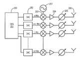
- FIG. 2is a circuit diagram illustrating an integrated amplifier and transmission circuit according to principles of the present invention.
- FIG. 3is a timing diagram illustrating the functionality of multiple transmitters according to principles of the present invention.
- the present inventionprovides a method and system for transmitting a multi-frequency signal composed of discrete tones of constant envelope parts that are amplified by a bank of fully saturated transmitters operating in their most power efficient mode. After amplification and transmission, the signals are multiplexed in the air as opposed to multiplexing before amplification, which allows for more efficient amplification as well.
- This conceptis related to U.S. Pat. No. 7,151,476, hereby incorporated by reference. Therefore, the present invention provides a wireless transmitter that operates at high efficiency while transmitting a multi-tone signal.
- the present inventionwill be more and more advantageous since both processing speed and power efficiency can still be improved, but are currently being held back by hardware technology. Furthermore, power efficiency of linear amplification, as is used in prior art MIMO techniques, is changing very slowly, if at all.
- the present inventionovercomes the limitation of linear amplification by placing the burden of efficiency on the processing of the tones, and utilizing amplifiers in their theoretically most efficient mode.
- a flow chart 100 of a preferred embodiment of the method of the present inventionis shown.
- the methodrelates generally to transmitting a multi-tone signal decomposed into a plurality of constant envelope signals over a multiple input multiple output (MIMO) system having two or more transmitting antennas.
- MIMOmultiple input multiple output
- step 101first and second signals having different frequencies and the same payload are generated.
- the first signalis transmitted on a first antenna and the second signal is transmitted on a second antenna in step 102 .
- the second signalis transmitted on the first antenna and the first signal is transmitted on the second antenna for the predetermined time period.
- a multi-frequency signalis generated as a composition of discrete tones, each tone being a constant envelope modulated signal.
- individual tonesare generated and modulated using digital signal processing.
- This processcan be carried out by a wave generator, or more specifically, by a direct digital synthesizer (DDS) 201 which is known in the art.
- DDSdirect digital synthesizer
- each generated toneis modulated using a constant envelope modulation scheme, such as frequency shifting or phase shift keying.
- Each modulated toneis then processed in one of a bank of separate digital to analogue converters (DAC) 202 .
- each DACconverts a digitally represented sampled waveform code to an analog signal that is either constant envelope or has very small peak to average power ratio for further processing.
- the signalsare passed to a bank of parallel single sideband mixers 203 driven by a frequency oscillator 207 .
- the signalsare upconverted to an appropriate transmission frequency band.
- the tonesthemselves are offset in frequency by an appropriate frequency separation as required by the signal being transmitted.
- the modulated tonesare orthogonal to facilitate digital frequency demultiplexing (e.g. filtering based on Discrete Fourier Transforms). Utilizing current hardware technology, it is reasonable to generate a dozen such tones separated by at least 1 MHz.
- each toneis then sent to a power amplifier 204 that operates at or near its saturation level.
- CMOS technology100 mW power is a realistic output power for each amplifier, with a combined transmit power well over 1 W. This level of operation is much more efficient than known prior art as the present invention utilizes fully saturated amplifiers operating at a much higher level of efficiency.
- Step 102Transmission of Signals
- the tonesare passed to a reactive circuit 205 that is preferably an on-chip circuit.
- This reactive circuit 205is used to match an antenna to a specific amplifier.
- the matching circuitis tuned to one of several widely differing carrier frequencies by switching a bank of capacitors or inductors. With this wideband tuning, carrier frequencies in the range of 900 MHz to 6000 MHz are achievable for broadcasting each tone.
- the purpose of the tuning elementsis to allow the antennas to operate with high efficiency operation (e.g., with very high return loss) across the fully available spectrum.
- These matching circuits 205 , or tuners as they are used in this case,are especially important for hand-held wireless devices where any signal radiating element will have to be very small and therefore inherently narrow band if to operate efficiently.
- the present inventionwill facilitate the transmission through the antennas with little reflectivity as each antenna will see only a narrowband part of the composite wideband signal at any given time.
- each individually generated, processed and amplified toneis transmitted through an antenna 206 .
- antennas 206There can be a varying amount of antennas 206 based upon the system design, but at the least there must be one antenna for each individual tone being transmitted.
- two antennasare used to broadcast two individual tones at separate frequencies.
- four antennasare used to transmit four individual tones, each antenna transmitting at a separate frequency.
- the modulated tonesare orthogonal. By transmitting different frequencies using separate antennas with their proper matching, the tones are radiated without mutual interaction in the air.
- Another known fault in the prior artis the power when utilizing a single amplifier has to be reduced to avoid tone-to-tone intersymbol interference caused by the nonlinear distortion of the amplifier.
- Step 103MIMO operation
- OFDMorthogonal frequency division multiple access
- MIMOmultiple input multiple output
- the modulated subcarriersare grouped together and each group is transmitted on the same carrier frequency through a power amplifier and an antenna.
- These groupsare all similar OFDM signals and are related to each other through their digital coding employed in the information encoder.
- the transmittersall transmit groups of modulated tones.
- a transmitterneeds to transmit a single tone at any given time through a bank of individual amplifiers. This is achieved by permitting the tones in time through the amplifier bank. By the end of transmission all the tones will have been transmitted through all amplifiers and antennas. In this way, MIMO operation is across both frequency and across time segments.
- FIG. 3shows an example process with four carrier frequencies to transmit over (e.g., f 1 , f 2 , f 3 , and f 4 ) over four separate amplifiers and antennas.
- tone 1is transmitted over antenna 1 at f 1 and tone 2 is transmitted over antenna 2 at f 2 , etc.
- the changesoccur in the next transmission steps.
- tone 1is transmitted over antenna 4 at f 1 and tone 2 is transmitted over antenna 1 at f 2 , etc.
- a third transmission stepinvolves tone 1 being transmitted over antenna 3 at f 1 and tone 2 being transmitted over antenna 4 at f 2 , etc.
- a fourth transmission stepinvolves tone 1 being transmitted over antenna 2 at f 1 and tone 2 being transmitted over antenna 3 at f 2 etc.
- the antennasare denoted by A 1 , A 2 , A 3 , A 4 and the time intervals t 1 , t 2 , t 3 , t 4 , and let A 1 (t k ) denote the frequency of the tone at time t k through antenna A 1 .
- the receivertherefore, can process these four transmissions corresponding to the same carrier frequencies as in any other conventional MIMO signal processing with the advantage of their being always constant envelope, hence higher transmit power and of lower or no distortion for the same amplifier.
- FIG. 3shows the time evolution of the four-tone signal transmitted through four saturated power amplifiers.
- Each transmittertransmits a fully saturated waveform on one of each carrier frequency f 1 , f 2 , f 3 , f 4 .
- the pictureshows a particular sequence of tone permutations but others are also possible.
- each modulated toneis sent at each frequency for a predetermined period of time as before.
- the carrier frequenciesare permuted periodically or some randomized manner. Randomization may be preferred in military application to improve the covertness of the signal.
- Each differently shaded block on FIG. 3represents a segment of constant envelope modulated waveform whose horizontal length corresponds to the time extent of that particular segment. This way, a four-tone signal is formed from constant envelope waveforms. If the modulations are orthogonal to each other for the particular tone spacing, then it is four-tone OFDM.
- the envelope of the resulting composite waveform of the several tonesis, of course, widely fluctuating as much as that of any conventional multi-tone signal, but the composite is formed in the air after radiation and after any power amplification. This as mentioned above, facilitates high efficiency amplification with low or no distortion.
- MIMO processingcan now be applied providing that it is recognized that under constant channel conditions, there is, as in the example illustrated in FIG. 3 , a four-tone signal along the time (horizontal) axis for each transmitter. Constant channel condition here is to be understood relative to the channel's coherence time in which communications is to take place.
- this approachis restricted by the channel coherence time. For example, in the embodiment described above, it needs to be at least four times longer than in normal MIMO processing.
- the power amplifiers used in this approachrequire at least 6 to 10 dB less peak power than in conventional OFDM or multi-tone system. In fact, if 1 W peak were needed in a comparable conventional OFDM, the transmission can be performed using CMOS technology.
- the transmitteris preferably a single CMOS or BiCMOS integrated circuit chip, although other semiconductor technologies are possible.
- the coherence timemay also be quite long, in which case this scheme is available and could be used without any hardware change to the existing four-transmitter OFDM MIMO radio.
- the present inventioncan be modified to accommodate various numbers of tones, antennas, and carrier frequencies.
Landscapes
- Engineering & Computer Science (AREA)
- Computer Networks & Wireless Communication (AREA)
- Signal Processing (AREA)
- Transmitters (AREA)
- Radio Transmission System (AREA)
- Amplifiers (AREA)
Abstract
Description
Claims (16)
Priority Applications (1)
| Application Number | Priority Date | Filing Date | Title |
|---|---|---|---|
| US11/753,225US8270513B2 (en) | 2006-05-31 | 2007-05-24 | Fully saturated multi-tone transceiver |
Applications Claiming Priority (2)
| Application Number | Priority Date | Filing Date | Title |
|---|---|---|---|
| US80990106P | 2006-05-31 | 2006-05-31 | |
| US11/753,225US8270513B2 (en) | 2006-05-31 | 2007-05-24 | Fully saturated multi-tone transceiver |
Publications (2)
| Publication Number | Publication Date |
|---|---|
| US20070280372A1 US20070280372A1 (en) | 2007-12-06 |
| US8270513B2true US8270513B2 (en) | 2012-09-18 |
Family
ID=38802003
Family Applications (1)
| Application Number | Title | Priority Date | Filing Date |
|---|---|---|---|
| US11/753,225Expired - Fee RelatedUS8270513B2 (en) | 2006-05-31 | 2007-05-24 | Fully saturated multi-tone transceiver |
Country Status (3)
| Country | Link |
|---|---|
| US (1) | US8270513B2 (en) |
| EP (1) | EP2092678A2 (en) |
| WO (1) | WO2007142950A2 (en) |
Cited By (3)
| Publication number | Priority date | Publication date | Assignee | Title |
|---|---|---|---|---|
| US20140235186A1 (en)* | 2013-02-15 | 2014-08-21 | Institut Polytechnique De Bordeaux | Radio frequency signal transmission method and device |
| US20160073582A1 (en)* | 2014-09-15 | 2016-03-17 | Kondex Corporation | Agricultural blades and machine parts with amorphous metal laser cladding |
| US20220321063A1 (en)* | 2018-01-26 | 2022-10-06 | Skyworks Solutions, Inc. | Universal memory-based model for nonlinear power amplifier behaviors |
Families Citing this family (4)
| Publication number | Priority date | Publication date | Assignee | Title |
|---|---|---|---|---|
| US9602228B1 (en) | 2013-01-18 | 2017-03-21 | Gregory R. Warnes | Method and apparatus for transmission and reception of a signal over multiple frequencies with time offset encoding at each frequency |
| NL1040028C2 (en)* | 2013-01-29 | 2014-08-04 | Avenir D Or B V L | Antenna system. |
| KR102183646B1 (en)* | 2015-12-02 | 2020-11-27 | 노키아 솔루션스 앤드 네트웍스 오와이 | Methods, systems and devices |
| CN107104605A (en)* | 2016-02-23 | 2017-08-29 | 成都凯天电子股份有限公司 | Multichannel power supply equipment for sensor |
Citations (19)
| Publication number | Priority date | Publication date | Assignee | Title |
|---|---|---|---|---|
| US5732113A (en) | 1996-06-20 | 1998-03-24 | Stanford University | Timing and frequency synchronization of OFDM signals |
| US5914933A (en) | 1996-03-08 | 1999-06-22 | Lucent Technologies Inc. | Clustered OFDM communication system |
| US6130918A (en) | 1997-12-01 | 2000-10-10 | Nortel Networks Limited | Method and apparatus for reducing the peak-to-average ratio in a multicarrier communication system |
| US6392588B1 (en) | 2000-05-03 | 2002-05-21 | Ramot University Authority For Applied Research & Industrial Development Ltd. | Multifrequency signal structure for radar systems |
| US20020176510A1 (en) | 2001-05-15 | 2002-11-28 | Flarion Technologies, Inc. | Multi - tone signal transmission methods and apparatus |
| US20050013379A1 (en) | 2003-06-24 | 2005-01-20 | Globespanvirata, Inc. | Technique for improving multiple-channel multi-tone transmissions |
| US6882619B1 (en) | 2001-02-21 | 2005-04-19 | At&T Corp. | Interference suppressing OFDM method for wireless communications |
| US20050175116A1 (en) | 1998-08-10 | 2005-08-11 | Kamilo Feher | OFDM, CDMA, spread spectrum,TDMA, cross-correlated and filtered modulation |
| US6944122B2 (en) | 1998-05-26 | 2005-09-13 | Matsushita Electric Industrial Co., Ltd. | Modulator, demodulator, and transmission system for use in OFDM transmission |
| US20060034389A1 (en)* | 2004-08-12 | 2006-02-16 | Tsuguhide Aoki | Wireless transmitting device and method |
| US7016431B2 (en) | 1999-12-23 | 2006-03-21 | Robert Bosch Gmbh | Transmitter for transmitting signals over radio channels and method for transmitting signals over radio channels |
| US20060146952A1 (en)* | 2005-01-04 | 2006-07-06 | Texas Instruments Incorporated | Scalable post-channel estimate phase corrector, method of correction and mimo communication system empolying the corrector and method |
| US20060222141A1 (en)* | 2005-03-28 | 2006-10-05 | Tyco Electronics Corporation | Electronic applicator counter |
| US7151476B2 (en) | 2004-06-28 | 2006-12-19 | M/A-Com, Inc. | Radar system having a beamless emission signature |
| US20070032266A1 (en)* | 2005-08-03 | 2007-02-08 | Kamilo Feher | GPS and non GPS position finder, emergency, MIMO, spread spectrum, CDMA, GSM and OFDM |
| US7184492B2 (en)* | 2003-02-10 | 2007-02-27 | Ericsson Inc. | Using antenna arrays in multipath environment |
| US20070058586A1 (en)* | 2005-09-09 | 2007-03-15 | Fujitsu Limited | Wireless telecommunication system, transmitter and receiver |
| US20070092020A1 (en)* | 2005-10-24 | 2007-04-26 | Fujitsu Limited | Radio communication method and system, and receiver apparatus and transmitter apparatus |
| US20070238483A1 (en)* | 2006-04-05 | 2007-10-11 | Olivier Boireau | Antenna sharing techniques |
- 2007
- 2007-05-24USUS11/753,225patent/US8270513B2/ennot_activeExpired - Fee Related
- 2007-05-30EPEP07795476Apatent/EP2092678A2/ennot_activeWithdrawn
- 2007-05-30WOPCT/US2007/012712patent/WO2007142950A2/enactiveApplication Filing
Patent Citations (19)
| Publication number | Priority date | Publication date | Assignee | Title |
|---|---|---|---|---|
| US5914933A (en) | 1996-03-08 | 1999-06-22 | Lucent Technologies Inc. | Clustered OFDM communication system |
| US5732113A (en) | 1996-06-20 | 1998-03-24 | Stanford University | Timing and frequency synchronization of OFDM signals |
| US6130918A (en) | 1997-12-01 | 2000-10-10 | Nortel Networks Limited | Method and apparatus for reducing the peak-to-average ratio in a multicarrier communication system |
| US6944122B2 (en) | 1998-05-26 | 2005-09-13 | Matsushita Electric Industrial Co., Ltd. | Modulator, demodulator, and transmission system for use in OFDM transmission |
| US20050175116A1 (en) | 1998-08-10 | 2005-08-11 | Kamilo Feher | OFDM, CDMA, spread spectrum,TDMA, cross-correlated and filtered modulation |
| US7016431B2 (en) | 1999-12-23 | 2006-03-21 | Robert Bosch Gmbh | Transmitter for transmitting signals over radio channels and method for transmitting signals over radio channels |
| US6392588B1 (en) | 2000-05-03 | 2002-05-21 | Ramot University Authority For Applied Research & Industrial Development Ltd. | Multifrequency signal structure for radar systems |
| US6882619B1 (en) | 2001-02-21 | 2005-04-19 | At&T Corp. | Interference suppressing OFDM method for wireless communications |
| US20020176510A1 (en) | 2001-05-15 | 2002-11-28 | Flarion Technologies, Inc. | Multi - tone signal transmission methods and apparatus |
| US7184492B2 (en)* | 2003-02-10 | 2007-02-27 | Ericsson Inc. | Using antenna arrays in multipath environment |
| US20050013379A1 (en) | 2003-06-24 | 2005-01-20 | Globespanvirata, Inc. | Technique for improving multiple-channel multi-tone transmissions |
| US7151476B2 (en) | 2004-06-28 | 2006-12-19 | M/A-Com, Inc. | Radar system having a beamless emission signature |
| US20060034389A1 (en)* | 2004-08-12 | 2006-02-16 | Tsuguhide Aoki | Wireless transmitting device and method |
| US20060146952A1 (en)* | 2005-01-04 | 2006-07-06 | Texas Instruments Incorporated | Scalable post-channel estimate phase corrector, method of correction and mimo communication system empolying the corrector and method |
| US20060222141A1 (en)* | 2005-03-28 | 2006-10-05 | Tyco Electronics Corporation | Electronic applicator counter |
| US20070032266A1 (en)* | 2005-08-03 | 2007-02-08 | Kamilo Feher | GPS and non GPS position finder, emergency, MIMO, spread spectrum, CDMA, GSM and OFDM |
| US20070058586A1 (en)* | 2005-09-09 | 2007-03-15 | Fujitsu Limited | Wireless telecommunication system, transmitter and receiver |
| US20070092020A1 (en)* | 2005-10-24 | 2007-04-26 | Fujitsu Limited | Radio communication method and system, and receiver apparatus and transmitter apparatus |
| US20070238483A1 (en)* | 2006-04-05 | 2007-10-11 | Olivier Boireau | Antenna sharing techniques |
Non-Patent Citations (7)
| Title |
|---|
| Cimini L J et al: "Clustered OFDM With Transmitter Diversity and Coding" Communications: The Key to Global Prosperity. GLOBECOM 1996. London, Nov. 18-22, 1986, Global Telecommunications Conference (GLOBECOM), New York, IEEE, US, vol. 1, Nov. 18, 1996, pp. 703-707. |
| International Search Report, International application No. PCT/US2007/012712, International filed May 30, 2007. |
| Kaiser S Ed-Institute of Electrical and Electronics Engineers: "Spatial Transmit Diversity Techniques for Broadband OFDM Systems" GLOBECOM'00. 2000 IEEE Global Telecommunications Conference. San Francisco, CA, Nov. 27-Dec. 1, 2000, IEEE Global Telecommunications Conference, New York, NY: IEEE, US, vol. 3 of 3, Nov. 27, 2000, pp. 1824-1828. |
| Kaiser S Ed—Institute of Electrical and Electronics Engineers: "Spatial Transmit Diversity Techniques for Broadband OFDM Systems" GLOBECOM'00. 2000 IEEE Global Telecommunications Conference. San Francisco, CA, Nov. 27-Dec. 1, 2000, IEEE Global Telecommunications Conference, New York, NY: IEEE, US, vol. 3 of 3, Nov. 27, 2000, pp. 1824-1828. |
| Quachani I et al: "Trading rate versus diversity in space-time-frequency block coding schemes" Control, Communications and Signal Processing, 2004. First International Symposium on Hammamet, Tunisia Mar. 21-24, 2004, Piscataway, NJ, USA, IEEE, Mar. 21, 2004, pp. 171-174. |
| van Zelst, Allert, Student Member, IEEE; Schenk, Tim, C.W., Student Member, IEEE; Implementation of a MIMO OFDM-Based Wireless LAN System, Feb. 2004, IEEE Transactions on Signal Processing, vol. 52, No. 2, pp. 483-494. |
| Zhang, Zhan; Ilow, Jacek; Frequency Domain Equalization for MIMO Space-Time Transmissions with Single Carrier Signaling, The 14th IEEE 2003 International Symposium on Personal, Indoor and Mobile Radio Communication Proceedings, pp. 2262-2266. |
Cited By (6)
| Publication number | Priority date | Publication date | Assignee | Title |
|---|---|---|---|---|
| US20140235186A1 (en)* | 2013-02-15 | 2014-08-21 | Institut Polytechnique De Bordeaux | Radio frequency signal transmission method and device |
| US9270300B2 (en)* | 2013-02-15 | 2016-02-23 | Stmicroelectronics Sa | Radio frequency signal transmission method and device |
| US20160073582A1 (en)* | 2014-09-15 | 2016-03-17 | Kondex Corporation | Agricultural blades and machine parts with amorphous metal laser cladding |
| US9717176B2 (en)* | 2014-09-15 | 2017-08-01 | Kondex Corporation | Agricultural blades and machine parts with amorphous metal laser cladding |
| US20220321063A1 (en)* | 2018-01-26 | 2022-10-06 | Skyworks Solutions, Inc. | Universal memory-based model for nonlinear power amplifier behaviors |
| US11658617B2 (en)* | 2018-01-26 | 2023-05-23 | Skyworks Solutions, Inc. | Universal memory-based model for nonlinear power amplifier behaviors |
Also Published As
| Publication number | Publication date |
|---|---|
| US20070280372A1 (en) | 2007-12-06 |
| EP2092678A2 (en) | 2009-08-26 |
| WO2007142950A3 (en) | 2008-02-28 |
| WO2007142950A2 (en) | 2007-12-13 |
Similar Documents
| Publication | Publication Date | Title |
|---|---|---|
| US8270513B2 (en) | Fully saturated multi-tone transceiver | |
| EP1692836B1 (en) | Multi-carrier transmitter assembly | |
| KR100830614B1 (en) | Signal transmission system using multiple antenna and signal transmission method thereof | |
| US6175555B1 (en) | Transmit/receive compensation | |
| CN1285223C (en) | Multi-carrier CDMA transmission system with frequency and transmit diversity | |
| US6091715A (en) | Hybrid radio transceiver for wireless networks | |
| JP4875072B2 (en) | Multicarrier constant envelope signaling for power efficient and bandwidth efficient communication | |
| WO2001071928A3 (en) | High efficiency, high performance communications system employing multi-carrier modulation | |
| US6973118B1 (en) | Digital broadcasting apparatus | |
| KR19990014914A (en) | Dual Orthogonal Code and Frequency Division Multiple Access Communication System | |
| CA2566487A1 (en) | Time varying cyclic delay diversity of ofdm | |
| JPH04296684A (en) | Digital beamforming network and digital beamforming method | |
| JPH11504168A (en) | Practical means for digital generation and combination of multiple CDMA / FDMA signals | |
| US6411645B1 (en) | Modulation apparatus of multicarrier direct sequence spread spectrum communication system | |
| US7330513B2 (en) | Apparatus of transmitter and receiver for MIMO MC-CDMA system | |
| KR20060013497A (en) | Method and transmitter for transmitting data in a multi-carrier system via multiple transmit antennas | |
| US11362869B2 (en) | Method, transmitter, structure, transceiver and access point for provision of multi-carrier on-off keying signal | |
| JP4488190B2 (en) | Method for generating FSK symbols in a communication network and OFDM transmitter | |
| KR20120092634A (en) | Signal transmission and reception apparatus using on-off modulation | |
| US20220116251A1 (en) | Structure, method, transmitter, transceiver and access point suitable for low-complexity implementation | |
| Ishimura et al. | Simultaneous transmission of aggregated microwave and millimeter-wave signals over fiber with parallel IM/PM transmitter for mobile fronthaul links | |
| US20040235419A1 (en) | Method and system for broadcasting information from a satellite | |
| EP1678838A1 (en) | Multi-channel coded orthogonal frequency division modulation system | |
| JP2024108041A (en) | Radio transmission device and radio transmission method | |
| WO2002003641A1 (en) | Cofdm transmitter with diversity and time delay |
Legal Events
| Date | Code | Title | Description |
|---|---|---|---|
| AS | Assignment | Owner name:M/A-COM, INC., MASSACHUSETTS Free format text:ASSIGNMENT OF ASSIGNORS INTEREST;ASSIGNORS:EGRI, ROBERT;PERRAND, LAURENT;REEL/FRAME:019354/0614;SIGNING DATES FROM 20070522 TO 20070523 Owner name:M/A-COM, INC., MASSACHUSETTS Free format text:ASSIGNMENT OF ASSIGNORS INTEREST;ASSIGNORS:EGRI, ROBERT;PERRAND, LAURENT;SIGNING DATES FROM 20070522 TO 20070523;REEL/FRAME:019354/0614 | |
| AS | Assignment | Owner name:COBHAM DEFENSE ELECTRONIC SYSTEMS CORPORATION, MAS Free format text:ASSIGNMENT OF ASSIGNORS INTEREST;ASSIGNORS:M/A COM, INC.;RAYCHEM INTERNATIONAL;TYCO ELECTRONICS CORPORATION;AND OTHERS;REEL/FRAME:022266/0400;SIGNING DATES FROM 20080108 TO 20090113 Owner name:COBHAM DEFENSE ELECTRONIC SYSTEMS CORPORATION,MASS Free format text:ASSIGNMENT OF ASSIGNORS INTEREST;ASSIGNORS:M/A COM, INC.;RAYCHEM INTERNATIONAL;TYCO ELECTRONICS CORPORATION;AND OTHERS;SIGNING DATES FROM 20080108 TO 20090113;REEL/FRAME:022266/0400 Owner name:COBHAM DEFENSE ELECTRONIC SYSTEMS CORPORATION, MAS Free format text:ASSIGNMENT OF ASSIGNORS INTEREST;ASSIGNORS:M/A COM, INC.;RAYCHEM INTERNATIONAL;TYCO ELECTRONICS CORPORATION;AND OTHERS;SIGNING DATES FROM 20080108 TO 20090113;REEL/FRAME:022266/0400 | |
| REMI | Maintenance fee reminder mailed | ||
| LAPS | Lapse for failure to pay maintenance fees | ||
| STCH | Information on status: patent discontinuation | Free format text:PATENT EXPIRED DUE TO NONPAYMENT OF MAINTENANCE FEES UNDER 37 CFR 1.362 | |
| FP | Lapsed due to failure to pay maintenance fee | Effective date:20160918 | |
| AS | Assignment | Owner name:SENSOR AND ANTENNA SYSTEMS, LANSDALE, INC., MASSACHUSETTS Free format text:MERGER;ASSIGNOR:COBHAM DEFENSE ELECTRONIC SYSTEMS CORPORATION;REEL/FRAME:055793/0619 Effective date:20140929 | |
| AS | Assignment | Owner name:COBHAM ADVANCED ELECTRONIC SOLUTIONS INC., MASSACHUSETTS Free format text:CHANGE OF NAME;ASSIGNOR:SENSOR AND ANTENNA SYSTEMS, LANSDALE, INC.;REEL/FRAME:055822/0083 Effective date:20140929 |