US8270434B2 - Method and system for reducing transceiver power via a variable number of channels - Google Patents
Method and system for reducing transceiver power via a variable number of channelsDownload PDFInfo
- Publication number
- US8270434B2 US8270434B2US11/859,482US85948207AUS8270434B2US 8270434 B2US8270434 B2US 8270434B2US 85948207 AUS85948207 AUS 85948207AUS 8270434 B2US8270434 B2US 8270434B2
- Authority
- US
- United States
- Prior art keywords
- ethernet
- resources
- utilization
- channels
- availability
- Prior art date
- Legal status (The legal status is an assumption and is not a legal conclusion. Google has not performed a legal analysis and makes no representation as to the accuracy of the status listed.)
- Expired - Fee Related, expires
Links
- 238000000034methodMethods0.000titleclaimsabstractdescription22
- 239000000872bufferSubstances0.000claimsabstractdescription12
- 238000004590computer programMethods0.000claimsdescription5
- 238000012544monitoring processMethods0.000abstractdescription3
- 239000010410layerSubstances0.000description40
- 238000004891communicationMethods0.000description15
- 230000005540biological transmissionEffects0.000description14
- 238000010586diagramMethods0.000description10
- 230000000694effectsEffects0.000description5
- 230000008859changeEffects0.000description4
- 230000011664signalingEffects0.000description4
- 230000008901benefitEffects0.000description3
- 238000006243chemical reactionMethods0.000description3
- RYGMFSIKBFXOCR-UHFFFAOYSA-NCopperChemical compound[Cu]RYGMFSIKBFXOCR-UHFFFAOYSA-N0.000description2
- 230000003044adaptive effectEffects0.000description2
- 229910052802copperInorganic materials0.000description2
- 239000010949copperSubstances0.000description2
- 238000001514detection methodMethods0.000description2
- 238000005516engineering processMethods0.000description2
- 230000006870functionEffects0.000description2
- 239000002346layers by functionSubstances0.000description2
- 239000000463materialSubstances0.000description2
- 230000006855networkingEffects0.000description2
- 238000012545processingMethods0.000description2
- 230000007704transitionEffects0.000description2
- 101100458289Drosophila melanogaster msps geneProteins0.000description1
- 238000013459approachMethods0.000description1
- 238000010348incorporationMethods0.000description1
- 230000010365information processingEffects0.000description1
- 238000012986modificationMethods0.000description1
- 230000004048modificationEffects0.000description1
- 238000005192partitionMethods0.000description1
- 230000004044responseEffects0.000description1
- 239000000758substrateSubstances0.000description1
- 238000012546transferMethods0.000description1
Images


Classifications
- H—ELECTRICITY
- H04—ELECTRIC COMMUNICATION TECHNIQUE
- H04L—TRANSMISSION OF DIGITAL INFORMATION, e.g. TELEGRAPHIC COMMUNICATION
- H04L12/00—Data switching networks
- H04L12/28—Data switching networks characterised by path configuration, e.g. LAN [Local Area Networks] or WAN [Wide Area Networks]
- H04L12/40—Bus networks
- H04L12/407—Bus networks with decentralised control
- H04L12/413—Bus networks with decentralised control with random access, e.g. carrier-sense multiple-access with collision detection [CSMA-CD]
- H—ELECTRICITY
- H04—ELECTRIC COMMUNICATION TECHNIQUE
- H04L—TRANSMISSION OF DIGITAL INFORMATION, e.g. TELEGRAPHIC COMMUNICATION
- H04L12/00—Data switching networks
- H04L12/28—Data switching networks characterised by path configuration, e.g. LAN [Local Area Networks] or WAN [Wide Area Networks]
- H04L12/40—Bus networks
- H04L12/40006—Architecture of a communication node
- H04L12/40039—Details regarding the setting of the power status of a node according to activity on the bus
- H—ELECTRICITY
- H04—ELECTRIC COMMUNICATION TECHNIQUE
- H04L—TRANSMISSION OF DIGITAL INFORMATION, e.g. TELEGRAPHIC COMMUNICATION
- H04L12/00—Data switching networks
- H04L12/28—Data switching networks characterised by path configuration, e.g. LAN [Local Area Networks] or WAN [Wide Area Networks]
- H04L12/40—Bus networks
- H04L12/4013—Management of data rate on the bus
- H04L12/40136—Nodes adapting their rate to the physical link properties
- Y—GENERAL TAGGING OF NEW TECHNOLOGICAL DEVELOPMENTS; GENERAL TAGGING OF CROSS-SECTIONAL TECHNOLOGIES SPANNING OVER SEVERAL SECTIONS OF THE IPC; TECHNICAL SUBJECTS COVERED BY FORMER USPC CROSS-REFERENCE ART COLLECTIONS [XRACs] AND DIGESTS
- Y02—TECHNOLOGIES OR APPLICATIONS FOR MITIGATION OR ADAPTATION AGAINST CLIMATE CHANGE
- Y02D—CLIMATE CHANGE MITIGATION TECHNOLOGIES IN INFORMATION AND COMMUNICATION TECHNOLOGIES [ICT], I.E. INFORMATION AND COMMUNICATION TECHNOLOGIES AIMING AT THE REDUCTION OF THEIR OWN ENERGY USE
- Y02D30/00—Reducing energy consumption in communication networks
- Y02D30/50—Reducing energy consumption in communication networks in wire-line communication networks, e.g. low power modes or reduced link rate
Definitions
- Certain embodiments of the inventionrelate to networking. More specifically, certain embodiments of the invention relate to a method and system for low reducing transceiver power via a variable number of channels.
- Ethernet networksare increasingly being relied on to transmit various types and sizes of data for a variety of applications.
- Ethernet networksare increasingly being utilized to carry, for example, voice, data, and multimedia. Due to the rapidly increasing dependence on Ethernet networks, an increasing number and types of devices are being equipped to interface to Ethernet networks.
- a system and/or methodfor reducing transceiver power via a variable number of channels, substantially as shown in and/or described in connection with at least one of the figures, as set forth more completely in the claims.
- FIG. 1is a block diagram illustrating an Ethernet connection between a local link partner and a remote link partner, in connection with an embodiment of the invention.
- FIG. 2is a block diagram illustrating an exemplary Ethernet over twisted pair PHY device architecture comprising a multi-rate physical block, in accordance with an embodiment of the invention.
- FIG. 3is a diagram illustrating exemplary activity on an Ethernet channel, in accordance with an embodiment of the invention.
- FIG. 4is a diagram illustrating an exemplary system enabled for reduced power consumption during periods of low link utilization, in accordance with an embodiment of the invention.
- FIG. 5is a diagram illustrating alternating channels being placed in a low(er) power state, in accordance with an embodiment of the invention.
- FIG. 6is a flow chart illustrating exemplary steps for varying a channel configuration in an Ethernet network, in accordance with an embodiment of the invention.
- Certain embodiments of the inventionmay be found in a method and system for reducing transceiver power via a variable number of channels.
- utilization and/or availability of network resources and/or device resourcesmay be determined and a configuration of channels utilized for transmitting data may be determined based on the determined utilization and/or availability of resources.
- the number of channels over which data is communicatedmay be altered based on thresholds for the utilization and/or availability of resources.
- the configuration of channels utilized for communicating datamay be dynamically altered by monitoring changes to the utilization and/or availability of resources.
- the number of channelsmay be altered based on available bandwidth on one or more channels, based on capacity and/or available space of one or more buffers, and/or based on available power or desired power consumption of a transmitter.
- Aspects of the inventionmay be found in, for example, Ethernet PHY devices which transmit at data rates of 1 Gbps and higher.
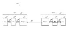
- FIG. 1is a block diagram illustrating an Ethernet connection between a local link partner and a remote link partner, in accordance with an embodiment of the invention.
- a system 100that comprises a local link partner 102 and a remote link partner 104 .
- the local link partner 102 and the remote link partner 104communicate via a cable 112 .
- the cable 112may comprise up to four or more channels, each of which may, for example, comprise an unshielded twisted pair (UTP).
- the local link partner 102 and the remote link partner 104may communicate via two or more channels comprising the cable 112 .
- Ethernet over twisted pair standards 10 Base-T and 100 Base-TXmay utilize two pairs of UTP while Ethernet over twisted pair standards 1000 Base-T and 10 GBase-T may utilize four pairs of UTP.
- the local link partner 102may comprise a host 106 a , a medium access control (MAC) controller 108 a , and a PHY device 104 a .
- the remote link partner 104may comprise a host 106 b , a MAC controller 108 b , and a PHY device 110 b .
- the link partner 102 and/or 104may comprise, for example, computer systems or audio/video (A/V) enabled equipment.
- A/V equipmentmay, for example, comprise, a microphone, an instrument, a sound board, a sound card, a video camera, a media player, a graphics card, or other audio and/or video device.
- the link partners 102 and 104may be enabled to utilize Audio/Video Bridging and/or Audio/video bridging extensions (collectively referred to herein as AVB) for the exchange of multimedia content and associated control and/or auxiliary data.
- AVBAudio/Video Bridging and/or Audio/video bridging extensions
- the PHY devices 110 a and 110 bmay each comprise suitable logic, circuitry, and/or code that may enable communication, for example, transmission and reception of data, between the local link partner 102 and the remote link partner 104 .
- the PHY devices 110 a and 110 bmay support, for example, Ethernet operations.
- the PHY devices 110 a and 110 bmay enable multi-rate communications, such as 10 Mbps, 100 Mbps, 1000 Mbps (or 1 Gbps), 2.5 Gbps, 4 Gbps, 10 Gbps, or 40 Gbps, for example.
- the PHY devices 110 a and 110 bmay support standard-based data rates and/or non-standard data rates.
- the PHY devices 110 a and 110 bmay support standard Ethernet link lengths or ranges of operation and/or extended ranges of operation.
- the PHY devices 110 a and 110 bmay enable communication between the local link partner 102 and the remote link partner 104 by utilizing a link discovery signaling (LDS) operation that enables detection of active operations in the other link partner.
- LDSlink discovery signaling
- the LDS operationmay be configured for supporting a standard Ethernet operation and/or an extended range Ethernet operation.
- the PHY devices 110 a and 110 bmay also support autonegotiation for identifying and selecting communication parameters such as speed and duplex mode.
- the PHY devices 110 a and 110 bmay be enabled to select the fastest configuration supported by both.
- the PHY devices 110 a and 110 bmay comprise suitable logic, circuitry, and/or code that may enable transmission and/or reception at a high(er) data in one direction and transmission and/or reception at a low(er) data rate in the other direction.
- the local link partner 102may comprise a multimedia server and the remote link partner 104 may comprise a multimedia client.
- the local link partner 102may transmit multimedia data, for example, to the remote partner 104 at high(er) data rates while the remote link partner 104 may transmit control or auxiliary data associated with the multimedia content at low(er) data rates.
- the data transmitted and/or received by the PHY devices 110 a and 110 bmay be formatted in accordance with the well-known OSI protocol standard.
- the OSI modelpartitions operability and functionality into seven distinct and hierarchical layers. Generally, each layer in the OSI model is structured so that it may provide a service to the immediately higher interfacing layer. For example, layer 1, or physical layer, may provide services to layer 2 and layer 2 may provide services to layer 3.
- the data transmittedmay comprise frames of Ethernet media independent interface (MII) data which may be delimited by start of stream and end of stream delimiters, for example.
- the data transmittedmay also comprise IDLE symbols that may be communicated between frames of data.
- MIIEthernet media independent interface
- the hosts 106 a and 106 bmay represent layer 3 and above, the MAC controllers 108 a and 108 b may represent layer 2 and above and the PHY devices 110 a and 110 b may represent the operability and/or functionality of layer 1 or the physical layer.
- the PHY devices 110 a and 110 bmay be referred to as Physical layer transmitters and/or receivers, physical layer transceivers, PHY transceivers, PHYceivers, or PHY, for example.
- the hosts 106 a and 106 bmay comprise suitable logic, circuitry, and/or code that may enable operability and/or functionality of the five highest functional layers for data packets that are to be transmitted over the cable 112 . Since each layer in the OSI model provides a service to the immediately higher interfacing layer, the MAC controllers 108 a and 108 b may provide the necessary services to the hosts 106 a and 106 b to ensure that packets are suitably formatted and communicated to the PHY devices 110 a and 110 b . During transmission, each layer adds its own header to the data passed on from the interfacing layer above it. However, during reception, a compatible device having a similar OSI stack may strip off the headers as the message passes from the lower layers up to the higher layers.
- the PHY devices 110 a and 110 bmay be configured to handle all the physical layer requirements, which include, but are not limited to, packetization, data transfer and serialization/deserialization (SERDES), in instances where such an operation is required.
- Data packets received by the PHY devices 110 a and 110 b from MAC controllers 108 a and 108 b , respectively,may include data and header information for each of the above six functional layers.
- the PHY devices 110 a and 110 bmay be configured to encode data packets that are to be transmitted over the cable 112 and/or to decode data packets received from the cable 112 .
- the MAC controller 108 amay comprise suitable logic, circuitry, and/or code that may enable handling of data link layer, layer 2, operability and/or functionality in the local link partner 102 .
- the MAC controller 108 bmay comprise suitable logic, circuitry, and/or code that may enable handling of layer 2 operability and/or functionality in the remote link partner 104 .
- the MAC controllers 108 a and 108 bmay be configured to implement Ethernet protocols, such as those based on the IEEE 802.3 standard, for example. Notwithstanding, the invention is not limited in this regard.
- the MAC controller 108 amay communicate with the PHY device 110 a via an interface 114 a and with the host 106 a via a bus controller interface 116 a .
- the MAC controller 108 bmay communicate with the PHY device 110 b via an interface 114 b and with the host 106 b via a bus controller interface 116 b .
- the interfaces 114 a and 114 bcorrespond to Ethernet interfaces that comprise protocol and/or link management control signals.
- the interfaces 114 a and 114 bmay be multi-rate interfaces and/or media independent interfaces (MII).
- the bus controller interfaces 116 a and 116 bmay correspond to PCI or PCI-X interfaces. Notwithstanding, the invention is not limited in this regard.
- PHY devicessuch as the PHY devices 110 a and 110 b may conventionally transmit data via a fixed number of channels which may result in network links being underutilized for significant portions of time.
- conventional PHY devicesmay distribute traffic evenly over all available channels and may continuously transmit IDLE symbols between packets of actual data.
- conventional PHY devicesmay use a significant amount of power transmitting at a higher data rate than necessary.
- aspects of the inventionmay enable varying the number of channels that may be utilized. In this regards, the number of channels over which data may be transmitted may be reduced when link utilization is low and/or when network or device resources (e.g., power, buffer space, processor time, etc.) are limited.
- the number of channels over which data may be transmittedmay be increased when link utilization is high and/or when resources (e.g., power, buffers, processor time, etc.) are limited.
- bit error rates and/or packet error rates of one or more channels comprising the cable 112may be a factor in determining a configuration of channels for communication between the link partners 102 and 104 .
- aspects of the inventionmay enable powering that channel down and communicating over remaining channels comprising the cable 112 .
- aspects of the inventionmay enable increasing the number of channels such that data rates may be maintained but symbol rates may be reduced.
- the link partner 102may initially transmit data via a first, high(er), data rate via a high(er) number of channels and may determine that the first, high(er) data rate is unnecessary. Accordingly, the link partner 102 may reduce the number of channels over which data may be transmitted. In this regard, the link partner 102 may need a way to coordinate which channels and/or how many channels may be utilized to transmit data to the link partner 104 . In this manner, coordinating a change in the transmission channels may prevent receive errors at the link partner 104 . Accordingly, aspects of the invention may enable the link partner 102 to transmit one or more symbols to indicate a forthcoming change in which channels and/or how many channels may be utilized to transmit data.
- one or more unique symbolsmay be defined to identify each of a plurality of possible channels and/or channel combinations. Accordingly, in various embodiments of the invention, prior to changing to a particular channel and/or changing the number of channels that may be utilized for transmitting data, the link partner 102 may transmit one or more symbols which signals a forthcoming change in channels. Moreover, the symbols which identify changes in a channel configuration may be in addition to, in place of, or a modified form of conventional IDLE symbols. In various embodiments of the invention, the new symbol rate may be negotiated in a manner similar to autonegotiation.
- FIG. 2is a block diagram illustrating an exemplary Ethernet over twisted pair PHY device architecture comprising a multi-rate physical block, in accordance with an embodiment of the invention.
- a link partner 200which may comprises an Ethernet over twisted pair PHY device 202 , a MAC controller 204 , a host 206 , an interface 208 , and a bus controller interface 210 .
- the PHY device 202may be an integrated device which may comprise a multi-rate physical layer block 212 , one or more transmitters 214 , one or more receivers 220 , a memory 216 , a memory interface 218 , and one or more input/output interfaces 222 .
- the PHY device 202may be an integrated device that comprises a multi-rate physical layer block 212 , one or more transmitters 214 , one or more receivers 220 , a memory 216 , a memory interface 218 , and one or more input/output interfaces 222 .
- the operation of the PHY device 202may be the same as or substantially similar to that of the PHY devices 110 a and 110 b disclosed in FIG. 1 .
- the PHY device 202may provide layer 1 (physical layer) operability and/or functionality that enables communication with a remote PHY device.
- the operation of the MAC controller 204 , the host 206 , the interface 208 , and the bus controller 210may be the same as or substantially similar to the respective MAC controllers 108 a and 108 b , hosts 106 a and 106 b , interfaces 114 a and 114 b , and bus controller interfaces 116 a and 116 b as described in FIG. 1 .
- the MAC controller 204may comprise a multi-rate interface 204 a that may comprise suitable logic, circuitry, and/or code to enable communication with the PHY device 202 at a plurality of data rates via the interface 208 .
- the multi-rate physical layer block 212 in the PHY device 202may comprise suitable logic, circuitry, and/or code that may enable operability and/or functionality of physical layer requirements.
- the multi-rate physical layer block 212may enable generating the appropriate link discovery signaling utilized for establishing communication with a remote PHY device in a remote link partner.
- a 10base-T PHY devicemay transmit normal link pulses (NLPs) periodically.
- NLPsnormal link pulses
- 100 Base-TX, 1000 Base-T, and 10 Gbase-T PHY devicesmay transmit fast link pulse (FLP) bursts, where each burst comprises a train of NLPs.
- FLPfast link pulse
- the multi-rate physical layer block 212may communicate with the MAC controller 204 via the interface 208 .
- the interface 208may be a media independent interface (MII) and may be configured to utilize a plurality of serial data lanes for receiving data from the multi-rate physical layer block 212 and/or for transmitting data to the multi-rate physical layer block 212 , in order to achieve higher operational speeds such as 1 Gbps or 10 Gbps, for example.
- the multi-rate physical layer block 212may be configured to operate in one or more of a plurality of communication modes, where each communication mode may implement a different communication protocol.
- the multi-rate physical layer block 212may be configured to operate in a particular mode of operation upon initialization or during operation. For example, auto-negotiation may utilize the FLP bursts to establish a rate (e.g. 10 Mbps, 100 Mbps, 1000 Mbps, or 10 Gbps) and mode (half-duplex or full-duplex) for transmitting information.
- a ratee.g. 10 Mbps, 100 Mbps, 1000 Mbps, or 10 Gbps
- modehalf-duplex or full-duplex
- the multi-rate physical layer block 212may be coupled to memory 216 through the memory interface 218 , which may be implemented as a serial interface or a bus.
- the memory 216may comprise suitable logic, circuitry, and/or code that may enable storage or programming of information that includes parameters and/or code that may effectuate the operation of the multi-rate physical layer block 212 .
- the parametersmay comprise configuration data and the code may comprise operational code such as software and/or firmware, but the information need not be limited in this regard.
- the parametersmay include adaptive filter and/or block coefficients for use by the multi-rate physical layer block 212 , for example.
- Each of the transmitters 214 a , 214 b , 214 c , 214 dmay comprise suitable logic, circuitry, and/or code that may enable transmission of data from the link partner 200 to a remote link partner via, for example, the cable 112 in FIG. 1 .
- the receivers 220 a , 220 b , 220 c , 220 dmay comprise suitable logic, circuitry, and/or code that may enable receiving data from a remote link partner.
- Each of the transmitters 214 a , 214 b , 214 c , 214 d and receivers 220 a , 220 b , 220 c , 220 d in the PHY device 202may correspond to a channel that may comprise the cable 112 .
- a transmitter/receiver pairmay interface with each of the channels 224 a , 224 b , 224 c , 224 d .
- the transmitter/receiver pairsmay be enabled to provide the appropriate communication rate and mode for each channel.
- the input/output interfaces 222may comprise suitable logic circuitry, and/or code that may enable the PHY device 202 to impress signal information onto a physical medium comprising a channel, for example a twisted pair channel comprising the cable 112 disclosed in FIG. 1 . Consequently, the input/output interfaces 222 may, for example, provide conversion between differential and single-ended, balanced and unbalanced, signaling methods. In this regard, the conversion may depend on the signaling method utilized by the transmitter 214 , the receiver 220 , and the type of medium comprising the channel. Accordingly, the input/output interfaces 222 may comprise one or more baluns and/or transformers and may, for example, enable transmission over a twisted pair.
- the input/output interfaces 222may be internal or external to the PHY device 202 .
- internalmay, for example, refer to being “on-chip” and/or sharing the same substrate.
- PHY device 202comprises one or more discrete components, then “internal” may, for example, refer to being on the same printed circuit board or being within a common physical package.
- the PHY device 202may be enabled to transmit and receive simultaneously over up to four or more physical links.
- the PHY device 202may be enabled to transmit and receive data at 1 Gbps, 10 Gbps or higher.
- the PHY device 202may be 1 GBASE-T and/or 10 GBASE-T compliant.
- the link partner 200may comprise a number of hybrids 226 corresponding to the number of physical links.
- Each hybrid 226may comprise suitable logic, circuitry, and/or code that may enable separating transmitted and received signals from a physical link.
- Each hybrid 226 in the local link partner 300may be communicatively coupled to an input/output interface 222 .
- the link partner 200may communicate with a remote partner via the cable 112 .
- the link partner 200may transmit data to and receive data from a remote partner via the channels 224 a , 224 b , 224 c , and 224 d .
- the link partner 200may transmit IDLE symbols to maintain synchronization with the remote link partner. In this manner, power consumption of a network may be largely independent of the amount of actual data being transmitted over the network.
- aspects of the inventionmay disable, or put into a low(er) power state, one or more of the channels 224 , when those one or more channels are not required to meet current and/or future demand of network and/or device resources, such as power, bandwidth, processor time, and buffer capacity.
- the link partner 200may communicate with a remote partner via, for example, the cable 112 .
- the link partner 200may transmit, for example, multimedia content to a remote partner via the channel 224 a and may receive control and/or auxiliary data associated with the multimedia content from the remote partner via the link 224 b .
- the link partner 200may be enabled to utilize AVB for the transmission and/or reception of data over the channels 224 a and/or 224 b .
- the link partnermay be enabled to transmit at a first data rate and receive at a second, possibly different, data rate.
- the link partner 200may transmit multimedia content via the channel 224 a at a data rate of 1 Gbps and may receive control data via the channel 224 b at a rate of 500 Mbps.
- multimedia contentmay be transmitted utilizing a first, high(er), number of channels and auxiliary and/or control data may be transmitted utilizing a second, low(er), number of channels. Transmitting auxiliary and/or control data utilizing a low(er) number of channels may result in power savings for the link partner 200 and/or a remote link partner with which the link partner 200 may communicate.
- FIG. 3is a diagram illustrating exemplary activity on an Ethernet channel, in accordance with an embodiment of the invention. Referring to FIG. 3 , there is shown an exemplary Ethernet frame 302 , preceded and followed by IDLE symbols 320 .
- the Ethernet frame 302may comprise a preamble 304 , destination MAC address field 306 , a source MAC address field 308 , an Ethertype field 310 , a data field 312 , and a frame check sequence (FCS) 314 .
- FCSframe check sequence
- the first 62 bits of the preamblemay be utilized to phase lock a receiving PHY device to a transmitting PHY device.
- the last 2 bits of the preamble, ‘11’may indicate the end of the preamble and that the next bit received may be real data.
- the final byte of the preamble(the last 8 bits ending in ‘11’) is also known as a start of frame delimiter (SFD) 316 .
- the first 8 bits of the preamblemay be replaced with a start of stream delimiter (SSD) 316 to indicate the end of an inter-frame gap and the beginning of a frame.
- the destination MAC address field 306may comprise information that may be utilized to identify the node that the frame is to be sent to.
- the source MAC address 308 fieldmay comprise information that may be utilized to identify the node that originated the frame.
- the Ethertype field 310may comprise information that may be utilized to identify the protocol (e.g. IPv4 or IPv6) being transported in the packet.
- the data field 312may contain the data being transmitted.
- the FCS 314may comprise information that may be utilized to provide error detection for the packet.
- the frame 302may be immediately followed by an end of sequence delimiter (ESD) 318 to indicate the end of a frame and the beginning of an inter-frame gap.
- ESDend of sequence delimiter
- Ethernet framesmay be transmitted utilizing a variable number of channels. For example, when an amount of data stored in one or more buffers is below a threshold, aspects of the invention may enable reducing the number of channels over which data may be transmitted. Similarly, when an amount of data stored in one or more buffers is above a threshold, for example, aspects of the invention may enable increasing the number of channels over which data may be transmitted.
- FIG. 4is a diagram illustrating an exemplary system enabled for reduced power consumption during periods of low link utilization, in accordance with an embodiment of the invention.
- four physical channels 500 a , 500 b , 500 c , and 500 dwhich may exist, for example, between two link partners such as the link partner 200 of FIG. 2 .
- power savingsmay be realized by reducing one or more channels to a low(er) power or reduced activity state.
- the data ratemay be reduced to 750 Mbp, 500 mbps, or 250 Mbps by disabling or putting into a low(er) power state, 1, 2, or 3, respectively, of the 4 channels 500 a , 500 b , 500 c , 500 d .
- channels put into a low(er) power statemay transmit signals to maintain link status.
- synchronization functions, equalization, automatic gain control, adaptive echo cancellation, or other signal processing operationsmay be maintained during low(er) power periods transmission so that a link partner may quickly transition between different data rates.
- a 10 Gbps Ethernet networkmay transmit on only a single channel with a data rate approximately 2.5 times slower than the conventional 800 Msps to provide a data rate of 1 Gbps.
- FIG. 5is a diagram illustrating alternating channels placed into a low(er) power state, in accordance with an embodiment of the invention. Referring to FIG. 5 there is activity on four channels 600 a , 600 b , 600 c , 600 d during intervals 602 to 616 .
- one or more channels comprising a cablemay be disabled during periods of low(er) activity.
- 3 of the 4 channels 600 a , 600 b , 600 c , 600 dmay be disabled or reduced to a low(er) power state and actual data may be transmitted on a reduced number of channels during a time interval.
- datamay be transmitted on the channel 600 b during the interval 616 , the channel 600 c during the interval 614 , the channel 600 d during the time interval 612 , and so forth.
- the length of the intervals 602 - 616may be chosen such that a minimum period of inactivity for each of the channels 600 a , 600 b , 600 c , and 600 d is maintained at less than a determined amount of time. In this manner, the length of the intervals 602 to 616 may be chosen such that each of the channels 600 a , 600 b , 600 c , and 600 d is able to maintain synchronization and/or other parameters necessary for the rapid transition to a higher data rate.
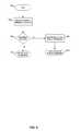
- FIG. 6is a flow chart illustrating exemplary step varying a channel configuration in an Ethernet network, in accordance with an embodiment of the invention.
- the exemplary stepsmay begin with a start step 602 .
- the exemplary stepsmay advance to step 604 .
- the state of one or more network channels and the availability of resources in the networkmay be determined.
- channel statemay comprise, for example, bit error rate, packet error rate, and channel utilization; and resources may comprise, for example, power, buffer space, and processor time.
- the exemplary stepsmay advance to step 606 .
- step 606it may be determined whether to alter the number of channels and/or which channels are utilized for network communication in response to the determined channel state and/or status of network resources and/or device resources. Accordingly, if the channel state and/or resource availability is outside of a determined range, a new channel configuration may be determined based on the channel status and/or condition of network resources and the exemplary steps may advance to step 608 .
- the new channel configurationmay be indicated to other nodes coupled to the channel via one or more transmitted symbols.
- the new ratemay be determined by a single or “master” node or may be negotiated between multiple nodes coupled to the channel.
- the exemplary stepsmay advance to step 610 . In step 610 , transmission of data at the symbol rate determined in step 606 may begin.
- step 606if the channel status and/or resources are within a determined range, or if a channel configuration change is determined to be unnecessary or not possible, then the exemplary steps may advance to step 614 .
- step 614transmission of data may continue over an unchanged channel configuration.
- the exemplary stepsmay periodically return to step 604 in order to monitor and/or discover changes to utilization and/or availability of resources.
- one or more flag bitsmay be asserted when utilization and/or availability of resources reaches a threshold.
- aspects of a method and system for reducing transceiver power via a variable number of channelsare provided.
- utilization and/or availability of network and/or device resourcesmay be determined and a configuration of channels, such as the channels 224 , utilized for transmitting data may be determined based on the determined utilization and/or availability of resources.
- the number of channels over which data is communicatedmay be altered based on determined thresholds for the utilization and/or availability of resources.
- the configuration of channels utilized for communicating datamay be dynamically altered by monitoring changes to the utilization and/or availability of resources.
- the number of channelsmay be altered based on available bandwidth on one or more channels, based on capacity and/or available space of one or more buffers, and/or based on available power or desired power consumption of a transmitter.
- Aspects of the inventionmay be found in, for example, Ethernet PHY devices which transmit at data rates of 1 Gbps and higher.
- Another embodiment of the inventionmay provide a machine-readable storage, having stored thereon, a computer program having at least one code section executable by a machine, thereby causing the machine to perform the steps as described herein for low reducing transceiver power via a variable number of channels.
- the present inventionmay be realized in hardware, software, or a combination of hardware and software.
- the present inventionmay be realized in a centralized fashion in at least one computer system, or in a distributed fashion where different elements are spread across several interconnected computer systems. Any kind of computer system or other apparatus adapted for carrying out the methods described herein is suited.
- a typical combination of hardware and softwaremay be a general-purpose computer system with a computer program that, when being loaded and executed, controls the computer system such that it carries out the methods described herein.
- the present inventionmay also be embedded in a computer program product, which comprises all the features enabling the implementation of the methods described herein, and which when loaded in a computer system is able to carry out these methods.
- Computer program in the present contextmeans any expression, in any language, code or notation, of a set of instructions intended to cause a system having an information processing capability to perform a particular function either directly or after either or both of the following: a) conversion to another language, code or notation; b) reproduction in a different material form.
Landscapes
- Engineering & Computer Science (AREA)
- Computer Networks & Wireless Communication (AREA)
- Signal Processing (AREA)
- Quality & Reliability (AREA)
- Small-Scale Networks (AREA)
Abstract
Description
Claims (27)
Priority Applications (2)
| Application Number | Priority Date | Filing Date | Title |
|---|---|---|---|
| US11/859,482US8270434B2 (en) | 2007-03-12 | 2007-09-21 | Method and system for reducing transceiver power via a variable number of channels |
| US13/601,996US8891395B2 (en) | 2007-03-12 | 2012-08-31 | Method and system for reducing transceiver power via a variable number of channels |
Applications Claiming Priority (3)
| Application Number | Priority Date | Filing Date | Title |
|---|---|---|---|
| US89424007P | 2007-03-12 | 2007-03-12 | |
| US91787007P | 2007-05-14 | 2007-05-14 | |
| US11/859,482US8270434B2 (en) | 2007-03-12 | 2007-09-21 | Method and system for reducing transceiver power via a variable number of channels |
Related Child Applications (1)
| Application Number | Title | Priority Date | Filing Date |
|---|---|---|---|
| US13/601,996ContinuationUS8891395B2 (en) | 2007-03-12 | 2012-08-31 | Method and system for reducing transceiver power via a variable number of channels |
Publications (2)
| Publication Number | Publication Date |
|---|---|
| US20080225894A1 US20080225894A1 (en) | 2008-09-18 |
| US8270434B2true US8270434B2 (en) | 2012-09-18 |
Family
ID=39762596
Family Applications (6)
| Application Number | Title | Priority Date | Filing Date |
|---|---|---|---|
| US11/859,459Active2028-07-02US8665902B2 (en) | 2007-03-12 | 2007-09-21 | Method and system for reducing transceiver power via a variable symbol rate |
| US11/859,482Expired - Fee RelatedUS8270434B2 (en) | 2007-03-12 | 2007-09-21 | Method and system for reducing transceiver power via a variable number of channels |
| US11/859,385Active2029-05-04US7920597B2 (en) | 2007-03-12 | 2007-09-21 | Method and system for low power idle signal transmission in ethernet networks |
| US11/859,429Active2029-12-17US8218567B2 (en) | 2007-03-12 | 2007-09-21 | Method and system for reducing transceiver power via a variable signal constellation |
| US13/492,602ActiveUS8509259B2 (en) | 2007-03-12 | 2012-06-08 | Method and system for reducing transceiver power via a variable signal constellation |
| US13/601,996Active2028-03-28US8891395B2 (en) | 2007-03-12 | 2012-08-31 | Method and system for reducing transceiver power via a variable number of channels |
Family Applications Before (1)
| Application Number | Title | Priority Date | Filing Date |
|---|---|---|---|
| US11/859,459Active2028-07-02US8665902B2 (en) | 2007-03-12 | 2007-09-21 | Method and system for reducing transceiver power via a variable symbol rate |
Family Applications After (4)
| Application Number | Title | Priority Date | Filing Date |
|---|---|---|---|
| US11/859,385Active2029-05-04US7920597B2 (en) | 2007-03-12 | 2007-09-21 | Method and system for low power idle signal transmission in ethernet networks |
| US11/859,429Active2029-12-17US8218567B2 (en) | 2007-03-12 | 2007-09-21 | Method and system for reducing transceiver power via a variable signal constellation |
| US13/492,602ActiveUS8509259B2 (en) | 2007-03-12 | 2012-06-08 | Method and system for reducing transceiver power via a variable signal constellation |
| US13/601,996Active2028-03-28US8891395B2 (en) | 2007-03-12 | 2012-08-31 | Method and system for reducing transceiver power via a variable number of channels |
Country Status (1)
| Country | Link |
|---|---|
| US (6) | US8665902B2 (en) |
Cited By (2)
| Publication number | Priority date | Publication date | Assignee | Title |
|---|---|---|---|---|
| US20100080132A1 (en)* | 2008-09-30 | 2010-04-01 | Sadagopan Srinivasan | Dynamic configuration of potential links between processing elements |
| US20110188519A1 (en)* | 2008-09-18 | 2011-08-04 | Yang Yu | Method and System for Communication Capacity Negotiation of Physical Layer Chips |
Families Citing this family (113)
| Publication number | Priority date | Publication date | Assignee | Title |
|---|---|---|---|---|
| US9323311B2 (en)* | 2006-06-22 | 2016-04-26 | Broadcom Corporation | Method and system for packet based signaling between A Mac and A PHY to manage energy efficient network devices and/or protocols |
| US20100115306A1 (en)* | 2008-11-05 | 2010-05-06 | Wael William Diab | Method and system for control of energy efficiency and associated policies in a physical layer device |
| US8576829B2 (en)* | 2006-08-08 | 2013-11-05 | Aeroscout, Ltd. | Multi-channel TDOA system |
| US8665902B2 (en)* | 2007-03-12 | 2014-03-04 | Broadcom Corporation | Method and system for reducing transceiver power via a variable symbol rate |
| US8615018B2 (en)* | 2007-03-12 | 2013-12-24 | Broadcom Corporation | Method and system for dynamically determining when to train ethernet link partners to support energy efficient ethernet networks |
| EP1976140A1 (en)* | 2007-03-26 | 2008-10-01 | Nokia Siemens Networks Gmbh & Co. Kg | Method and device for reducing transmission power of packet oriented data and communication system comprising such device |
| US8391354B2 (en)* | 2007-05-14 | 2013-03-05 | Broadcom Corporation | Method and system for transforming uncompressed video traffic to network-aware ethernet traffic with A/V bridging capabilities and A/V bridging extensions |
| US7962670B2 (en)* | 2007-06-06 | 2011-06-14 | Lantiq Deutschland Gmbh | Pin multiplexing |
| US7787375B2 (en)* | 2007-08-06 | 2010-08-31 | International Business Machines Corporation | Performing a recovery action in response to a credit depletion notification |
| US7975027B2 (en)* | 2007-08-06 | 2011-07-05 | International Business Machines Corporation | Credit depletion notification for transmitting frames between a port pair |
| US8102776B2 (en)* | 2007-09-05 | 2012-01-24 | Spirent Communications, Inc. | Methods and apparatus for generating simulated network traffic |
| US8532139B2 (en)* | 2007-09-21 | 2013-09-10 | Broadcom Corporation | Method and system for indicating a transition in rate and/or power consumption utilizing a distinct physical pattern on one or more idle channel(s) |
| US20090097401A1 (en) | 2007-10-12 | 2009-04-16 | Wael William Diab | Method and system for configurable data rate thresholds for energy efficient ethernet |
| US7864794B2 (en)* | 2007-10-12 | 2011-01-04 | Broadcom Corporation | Method and system for managing an energy efficient network utilizing audio video bridging |
| JP5240590B2 (en) | 2007-11-12 | 2013-07-17 | マーベル インターナショナル リミテッド | Active idle communication system |
| US8295163B1 (en)* | 2007-11-16 | 2012-10-23 | Marvell International Ltd. | Reassigning signals to cable channels |
| US8194548B2 (en)* | 2007-12-17 | 2012-06-05 | Broadcom Corporation | Method and system for duty cycling portions of a network device based on aggregate throughput of the device |
| US8724464B2 (en)* | 2007-12-17 | 2014-05-13 | Broadcom Corporation | Method and system for near continuous data rate limit adjustment via a plurality of link variables in an energy efficient network |
| US8588254B2 (en)* | 2007-12-17 | 2013-11-19 | Broadcom Corporation | Method and system for energy efficient signaling for 100mbps Ethernet using a subset technique |
| US9455912B2 (en)* | 2007-12-17 | 2016-09-27 | Broadcom Corporation | Method and system for a distinct physical pattern on an active channel to indicate a data rate transition for energy efficient ethernet |
| US8184572B1 (en)* | 2007-12-19 | 2012-05-22 | Rockwell Collins, Inc. | Real time control and management of a TDMA radio |
| US8326975B2 (en)* | 2008-01-18 | 2012-12-04 | Realtek Semiconductor Corp. | Power-saving network apparatus having physical layer circuit capable of entering low power state |
| US8127164B2 (en)* | 2008-02-12 | 2012-02-28 | Broadcom Corporation | System and method for energy savings on a PHY/MAC interface for energy efficient ethernet |
| US8276013B2 (en)* | 2008-02-13 | 2012-09-25 | Broadcom Corporation | System and method for reducing a link failure detection delay using a link energy signal while in a low power idle mode |
| US8130786B2 (en)* | 2008-03-14 | 2012-03-06 | Broadcom Corporation | Multi-rate backplane transceiver |
| US8670335B2 (en)* | 2008-04-02 | 2014-03-11 | Marvell World Trade Ltd. | Reduced power transmission |
| US8565269B2 (en)* | 2008-04-15 | 2013-10-22 | Broadcom Corporation | Method and system for MAC and PHY synchronization for energy efficient networking |
| US8275261B2 (en)* | 2008-04-17 | 2012-09-25 | Pmc Sierra Ltd | Power saving in IEEE 802-style networks |
| US7930373B2 (en)* | 2008-06-30 | 2011-04-19 | Broadcom Corporation | System and method for controlling a PHY attached to a MAC interface for energy efficient ethernet |
| US8270389B2 (en)* | 2008-08-11 | 2012-09-18 | Marvell International Ltd. | Method of synchronization for low power idle |
| TWI382711B (en)* | 2008-10-09 | 2013-01-11 | Realtek Semiconductor Corp | Communication device with adjustable consuming power and method thereof and ethernet communication device |
| US8982753B2 (en)* | 2008-11-05 | 2015-03-17 | Broadcom Corporation | Method and system for low latency state transitions for energy efficiency |
| US8107365B2 (en) | 2008-11-24 | 2012-01-31 | Cisco Technology, Inc. | Interim PHY solution for LPI compatibility with legacy devices |
| TWI424731B (en)* | 2008-12-03 | 2014-01-21 | Realtek Semiconductor Corp | Master device for an ethernet system and related clock synchronization method |
| US8279788B2 (en)* | 2009-01-12 | 2012-10-02 | Broadcom Corporation | Method and system for stateful negotiation of energy efficient parameters in layer 2 |
| EP2211479A1 (en)* | 2009-01-15 | 2010-07-28 | ABB Technology AG | Communication method and system |
| US8169999B2 (en) | 2009-01-16 | 2012-05-01 | Broadcom Corporation | Method and system for preserving content timing across femtocell interfaces via timestamp insertion |
| US8732501B1 (en) | 2009-02-09 | 2014-05-20 | Cisco Technology, Inc. | System and method for intelligent energy management in a network environment |
| US8352769B1 (en) | 2009-02-09 | 2013-01-08 | Cisco Technology, Inc. | System and method for querying for energy data in a network environment |
| US9118728B2 (en)* | 2009-03-04 | 2015-08-25 | Broadcom Corporation | Method and system for determining physical layer traversal time |
| US8995289B2 (en)* | 2009-03-04 | 2015-03-31 | Broadcom Corporation | Method and system for implementing energy efficient ethernet techniques in a MACSec enabled PHY |
| US8214665B2 (en)* | 2009-03-12 | 2012-07-03 | Broadcom Corporation | Method and system for transmit queue management for energy efficient networking |
| US8259617B2 (en) | 2009-03-18 | 2012-09-04 | Broadcom Corporation | Method and system for timely delivery of multimedia content via a femtocell |
| US8230240B2 (en)* | 2009-04-08 | 2012-07-24 | Broadcom Corporation | Method and system for energy efficient networking over a serial communication channel based on forward error correction support |
| US20100287402A1 (en)* | 2009-05-11 | 2010-11-11 | Electronics And Telecommunications Research Institute | Timestamping apparatus and method |
| US8462674B2 (en) | 2009-06-04 | 2013-06-11 | Broadcom Corporation | Method and system for symmetric transmit and receive latencies in an energy efficient PHY |
| US8295312B2 (en)* | 2009-06-08 | 2012-10-23 | Broadcom Corporation | Method and system for compensated time stamping for time-sensitive network communications |
| US20100312909A1 (en)* | 2009-06-08 | 2010-12-09 | Wael William Diab | Method and system for traffic based decisions for energy efficient networking |
| US9065736B2 (en) | 2009-06-08 | 2015-06-23 | Broadcom Corporation | Method and system for compensated time stamping for time-sensitive network communications |
| US8416774B2 (en)* | 2009-06-12 | 2013-04-09 | Broadcom Corporation | Method and system for energy-efficiency-based packet classification |
| US7936777B2 (en)* | 2009-06-19 | 2011-05-03 | Broadcom Corporation | Parallel detection of remote LPI request and send zero mode |
| US20120051748A1 (en)* | 2009-07-14 | 2012-03-01 | Mitsubishi Electric Corporation | Optical line terminal and pon system |
| US8300655B2 (en)* | 2009-07-31 | 2012-10-30 | Broadcom Corporation | System and method for dynamic power control for energy efficient physical layer communication devices |
| US8619604B2 (en)* | 2009-10-14 | 2013-12-31 | Broadcom Corporation | System and method for auto 10BASE-T/10BASE-Te selection based on cable characteristics |
| US8250392B2 (en)* | 2009-11-20 | 2012-08-21 | Lsi Corporation | Fast turn-on/off for energy efficient ethernet |
| US9712459B1 (en) | 2010-01-27 | 2017-07-18 | Marvell International Ltd. | Low-to-high speed cut-through communication |
| US8996900B2 (en)* | 2010-02-04 | 2015-03-31 | Cisco Technology, Inc. | System and method for managing power consumption in data propagation environments |
| US8621255B2 (en)* | 2010-02-18 | 2013-12-31 | Broadcom Corporation | System and method for loop timing update of energy efficient physical layer devices using subset communication techniques |
| US9026812B2 (en) | 2010-06-29 | 2015-05-05 | Cisco Technology, Inc. | System and method for providing intelligent power management in a network environment |
| JP5576212B2 (en)* | 2010-08-23 | 2014-08-20 | ラピスセミコンダクタ株式会社 | Information processing apparatus, communication system, information processing method, program, and irradiation apparatus |
| US9106360B2 (en) | 2011-03-30 | 2015-08-11 | University Of Houston | Methods and apparatus for traffic management in multi-mode switching DWDM networks |
| US9350423B2 (en)* | 2011-06-30 | 2016-05-24 | The Boeing Company | Methods and system for increasing data transmission rates across a three-phase power system |
| US8849473B2 (en) | 2011-08-17 | 2014-09-30 | Cisco Technology, Inc. | System and method for notifying and for controlling power demand |
| US8856570B2 (en)* | 2011-08-31 | 2014-10-07 | Broadcom Corporation | Energy efficiency ethernet with low power active idle transmission mode |
| US9058167B2 (en) | 2011-09-06 | 2015-06-16 | Cisco Technology, Inc. | Power conservation in a distributed digital video recorder/content delivery network system |
| US20130132745A1 (en) | 2011-11-22 | 2013-05-23 | Cisco Technology Inc. | System and method for network enabled wake for networks |
| US9141169B2 (en) | 2012-01-20 | 2015-09-22 | Cisco Technology, Inc. | System and method to conserve power in an access network without loss of service quality |
| GB2499050A (en)* | 2012-02-06 | 2013-08-07 | British Broadcasting Corp | Non-uniform QAM constellations with constellation points at positions of maximum capacity for a selected signal to noise ratio |
| US8767767B2 (en) | 2012-02-21 | 2014-07-01 | Honeywell International Inc. | System and method for out-of-band signaling |
| EP2823604B1 (en) | 2012-03-05 | 2017-04-19 | Qualcomm Incorporated | Low power idle signaling for gigabit media independent interfaces operating in legacy modes |
| US9130695B1 (en)* | 2012-03-06 | 2015-09-08 | Aquantia Corp. | Adaptive rate control of 10GBASE-T data transport system |
| CN104221290B (en)* | 2012-03-23 | 2017-11-07 | 高通股份有限公司 | Configurable Multimode Media Independent Interface |
| US8934372B2 (en)* | 2012-04-04 | 2015-01-13 | Broadcom Corporation | System and method for next generation BASE-T communication |
| US9735905B2 (en)* | 2012-08-10 | 2017-08-15 | Avago Technologies General Ip (Singapore) Pte. Ltd. | Systems and methods for implementing bi-directional synchronization propagation |
| US9105377B2 (en)* | 2012-11-13 | 2015-08-11 | Broadcom Corporation | System and method for enhanced auto-negotiation for NGBASE-T |
| US9958924B2 (en) | 2013-08-28 | 2018-05-01 | Cisco Technology, Inc. | Configuration of energy savings |
| WO2015176303A1 (en)* | 2014-05-23 | 2015-11-26 | Qualcomm Incorporated | Auto-detection of fiber working modes |
| CA2955623C (en) | 2014-07-25 | 2024-05-28 | Gatekeeper Systems, Inc. | Monitoring usage or status of cart retrievers |
| US10999124B1 (en)* | 2014-12-05 | 2021-05-04 | Marvell Asia Pte, Ltd. | Rapid rate adaptation in NBASE-T ethernet |
| JP2017027196A (en)* | 2015-07-17 | 2017-02-02 | 株式会社リコー | Communication device, power control method, and power control program |
| US10235516B2 (en) | 2016-05-10 | 2019-03-19 | Cisco Technology, Inc. | Method for authenticating a networked endpoint using a physical (power) challenge |
| US11165533B1 (en)* | 2016-07-28 | 2021-11-02 | Marvell Asia Pte, Ltd. | Ethernet over a reduced number of twisted pair channels |
| NO342582B1 (en)* | 2016-10-19 | 2018-06-18 | Roxar Flow Measurement As | Communication system for downhole network. |
| US10261923B2 (en)* | 2017-07-26 | 2019-04-16 | Intel Corporation | Configurable interconnect apparatus and method |
| US11115151B1 (en) | 2019-03-22 | 2021-09-07 | Marvell Asia Pte, Ltd. | Method and apparatus for fast retraining of ethernet transceivers based on trickling error |
| US11228465B1 (en) | 2019-03-22 | 2022-01-18 | Marvell Asia Pte, Ltd. | Rapid training method for high-speed ethernet |
| US10771100B1 (en) | 2019-03-22 | 2020-09-08 | Marvell Asia Pte., Ltd. | Method and apparatus for efficient fast retraining of ethernet transceivers |
| US11323435B2 (en) | 2019-05-08 | 2022-05-03 | The Boeing Company | Method and apparatus for advanced security systems over a power line connection |
| CN112019787B (en)* | 2019-05-31 | 2023-06-06 | 技嘉科技股份有限公司 | Motherboard and operating system capable of outputting image data |
| US11044044B2 (en) | 2019-07-16 | 2021-06-22 | Microsoft Technology Licensing, Llc | Peak to average power ratio reduction of optical systems utilizing error correction |
| US11075656B2 (en) | 2019-07-16 | 2021-07-27 | Microsoft Technology Licensing, Llc | Bit error reduction of communication systems using error correction |
| US11063696B2 (en) | 2019-07-16 | 2021-07-13 | Microsoft Technology Licensing, Llc | Increasing average power levels to reduce peak-to-average power levels using error correction codes |
| US11031961B2 (en) | 2019-07-16 | 2021-06-08 | Microsoft Technology Licensing, Llc | Smart symbol changes for optimization of communications using error correction |
| US11086719B2 (en) | 2019-07-16 | 2021-08-10 | Microsoft Technology Licensing, Llc | Use of error correction codes to prevent errors in neighboring storage |
| US11172455B2 (en) | 2019-07-16 | 2021-11-09 | Microsoft Technology Licensing, Llc | Peak to average power output reduction of RF systems utilizing error correction |
| US10911284B1 (en) | 2019-07-16 | 2021-02-02 | Microsoft Technology Licensing, Llc | Intelligent optimization of communication systems utilizing error correction |
| US10911141B1 (en) | 2019-07-30 | 2021-02-02 | Microsoft Technology Licensing, Llc | Dynamically selecting a channel model for optical communications |
| US10868580B1 (en)* | 2019-08-28 | 2020-12-15 | Marvell Asia Pte., Ltd. | Ethernet link transmit power method based on alien crosstalk feedback |
| CN111131265A (en)* | 2019-12-26 | 2020-05-08 | 武汉宏数信息技术有限责任公司 | Video encryption transmission method in engineering investigation design |
| US12081427B2 (en) | 2020-04-20 | 2024-09-03 | Mellanox Technologies, Ltd. | Time-synchronization testing in a network element |
| US11652698B2 (en)* | 2021-03-10 | 2023-05-16 | Arista Networks, Inc. | Virtual layer 1 (LI) connectivity across a network |
| US12111681B2 (en) | 2021-05-06 | 2024-10-08 | Mellanox Technologies, Ltd. | Network adapter providing isolated self-contained time services |
| US12021729B2 (en) | 2021-11-22 | 2024-06-25 | Spirent Communications, Inc. | Dual frame sequence tables for network testing |
| US12028155B2 (en)* | 2021-11-24 | 2024-07-02 | Mellanox Technologies, Ltd. | Controller which adjusts clock frequency based on received symbol rate |
| US11907754B2 (en) | 2021-12-14 | 2024-02-20 | Mellanox Technologies, Ltd. | System to trigger time-dependent action |
| US11835999B2 (en) | 2022-01-18 | 2023-12-05 | Mellanox Technologies, Ltd. | Controller which adjusts clock frequency based on received symbol rate |
| US12294469B2 (en) | 2022-05-12 | 2025-05-06 | Mellanox Technologies, Ltd | Boundary clock synchronized loop |
| US12308952B2 (en) | 2022-07-06 | 2025-05-20 | Mellanox Technologies, Ltd. | Companion metadata for precision time protocol (PTP) hardware clock |
| US12289388B2 (en) | 2022-07-20 | 2025-04-29 | Mellanox Technologies, Ltd | Syntonization through physical layer of interconnects |
| US11917045B2 (en) | 2022-07-24 | 2024-02-27 | Mellanox Technologies, Ltd. | Scalable synchronization of network devices |
| US12375199B2 (en) | 2022-12-19 | 2025-07-29 | Mellanox Technologies, Ltd | Hybrid clock synchronization |
| US12216489B2 (en) | 2023-02-21 | 2025-02-04 | Mellanox Technologies, Ltd | Clock adjustment holdover |
| US12289389B2 (en) | 2023-08-13 | 2025-04-29 | Mellanox Technologies, Ltd. | Physical layer syntonization using digitally controlled oscillator |
Citations (35)
| Publication number | Priority date | Publication date | Assignee | Title |
|---|---|---|---|---|
| GB2337672A (en) | 1998-05-20 | 1999-11-24 | 3Com Technologies Ltd | Reducing the data rate when idle state symbol errors exceed a threshold |
| WO2000031923A1 (en) | 1998-11-24 | 2000-06-02 | Koninklijke Philips Electronics N.V. | Data transmission system for reducing terminal power consumption in a wireless network |
| US6483870B1 (en) | 1997-10-15 | 2002-11-19 | Cisco Technology, Inc. | Data communication using a modifiable number of XDSL modems |
| US20020172274A1 (en) | 2001-05-18 | 2002-11-21 | Carlson Arthur J. | Method of intelligently restricting symbol size in ADSL modems |
| US20030137937A1 (en)* | 2002-01-22 | 2003-07-24 | Nippon Telegraph And Telephone Corp. | Capacity variable link apparatus and capacity variable link setting method |
| US6611503B1 (en)* | 1998-05-22 | 2003-08-26 | Tandberg Telecom As | Method and apparatus for multimedia conferencing with dynamic bandwidth allocation |
| US20030198224A1 (en)* | 2002-04-23 | 2003-10-23 | Via Technologies, Inc. | Method for filtering packets and associated controller |
| US20040006769A1 (en) | 2002-07-08 | 2004-01-08 | Ahmad Ansari | System for providing DBS and DSL video services to multiple television sets |
| US6724829B1 (en) | 1999-03-18 | 2004-04-20 | Conexant Systems, Inc. | Automatic power control in a data transmission system |
| US6732190B1 (en)* | 1999-03-09 | 2004-05-04 | Intel Corporation | Method and apparatus for conserving power consumed by a network interface device in packet filtering mode |
| US6763097B1 (en) | 1999-06-24 | 2004-07-13 | Coppergate Communications Ltd. | Source adaptive digital subscriber line and method |
| US6795450B1 (en) | 2000-09-28 | 2004-09-21 | Tdk Semiconductor Corporation | Method and apparatus for supporting physical layer link-suspend operation between network nodes |
| US6795407B2 (en)* | 2000-04-22 | 2004-09-21 | Atheros Communications, Inc. | Methods for controlling shared access to wireless transmission systems and increasing throughput of the same |
| EP1473870A2 (en) | 2003-05-01 | 2004-11-03 | Lucent Technologies Inc. | Adaptive sleeping and awakening protocol for an energy efficient adhoc network |
| EP1484876A2 (en) | 1995-11-06 | 2004-12-08 | Sun Microsystems, Inc. | Full duplex flow control for ethernet networks |
| EP1494407A1 (en) | 2003-06-30 | 2005-01-05 | Nokia Corporation | Low energy communication mode |
| US6856597B1 (en) | 2000-02-10 | 2005-02-15 | Paradyne Corporation | System and method for statistical control of power dissipation with host enforcement |
| US20060034295A1 (en) | 2004-05-21 | 2006-02-16 | Intel Corporation | Dynamically modulating link width |
| US7003333B2 (en) | 2002-09-17 | 2006-02-21 | Motorola, Inc. | Latch mechanism and electronic device employing a latch mechanism |
| US7050517B1 (en) | 2000-04-28 | 2006-05-23 | National Semiconductor Corporation | System and method suitable for receiving gigabit ethernet signals |
| US20060109864A1 (en)* | 2004-11-24 | 2006-05-25 | Infineon Technologies North American Corp. | Pre-emption mechanism for packet transport |
| US20060182139A1 (en)* | 2004-08-09 | 2006-08-17 | Mark Bugajski | Method and system for transforming video streams using a multi-channel flow-bonded traffic stream |
| US7116682B1 (en) | 2001-03-19 | 2006-10-03 | Cisco Technology, Inc. | Methods and apparatus for dynamic bandwidth adjustment |
| US20070280239A1 (en) | 2006-05-30 | 2007-12-06 | Martin Lund | Method and system for power control based on application awareness in a packet network switch |
| US7308058B2 (en) | 2003-10-27 | 2007-12-11 | Rambus Inc. | Transparent multi-mode PAM interface |
| US20070291775A1 (en)* | 2004-09-21 | 2007-12-20 | Michael Frantz | Self-Adapting Bandwidth Management |
| US7315967B2 (en) | 2003-07-31 | 2008-01-01 | Terayon Communication Systems, Inc. | Method and apparatus for automatic rate adaptation in a DOCSIS upstream |
| US20080049766A1 (en)* | 2006-08-25 | 2008-02-28 | Harrington Kendra S | Apparatus and method for range-confined communications |
| US20080056284A1 (en) | 2006-09-06 | 2008-03-06 | Scott Powell | Method and system for an asymmetric phy in extended range ethernet lans |
| US20080069014A1 (en) | 2006-09-19 | 2008-03-20 | Scott Powell | Method and system for an extended range ethernet link discovery signaling |
| US20080225841A1 (en) | 2007-03-12 | 2008-09-18 | Bruce Conway | Method and system for low power idle signal transmission in ethernet networks |
| US7555301B2 (en)* | 2002-11-21 | 2009-06-30 | Bandspeed, Inc. | Method and apparatus for coverage and throughput enhancement in a wireless communication system |
| US20090180529A1 (en) | 1998-11-09 | 2009-07-16 | Agazzi Oscar E | Multi-pair gigabit ethernet transceiver |
| US7656890B2 (en)* | 1999-10-13 | 2010-02-02 | Cisco Technology, Inc. | Downstream channel change technique implemented in an access network |
| US7782898B2 (en)* | 2003-02-04 | 2010-08-24 | Cisco Technology, Inc. | Wideband cable system |
Family Cites Families (49)
| Publication number | Priority date | Publication date | Assignee | Title |
|---|---|---|---|---|
| US6385203B2 (en)* | 1996-03-29 | 2002-05-07 | Cisco Technology, Inc. | Communication server apparatus and method |
| US5912895A (en)* | 1996-05-01 | 1999-06-15 | Northern Telecom Limited | Information network access apparatus and methods for communicating information packets via telephone lines |
| US5805597A (en)* | 1996-06-04 | 1998-09-08 | National Semiconductor Corporation | Method and apparatus for providing low power basic telephony type service over a twisted pair ethernet physical layer |
| JP3783363B2 (en)* | 1996-10-03 | 2006-06-07 | ソニー株式会社 | Data communication method, electronic apparatus, and physical layer integrated circuit |
| US6198776B1 (en)* | 1996-11-13 | 2001-03-06 | Motorola Inc. | Device and method for precoding data signals for PCM transmission |
| US6192422B1 (en)* | 1997-04-16 | 2001-02-20 | Alcatel Internetworking, Inc. | Repeater with flow control device transmitting congestion indication data from output port buffer to associated network node upon port input buffer crossing threshold level |
| US6542481B2 (en)* | 1998-06-01 | 2003-04-01 | Tantivy Communications, Inc. | Dynamic bandwidth allocation for multiple access communication using session queues |
| US6728216B1 (en)* | 1998-02-27 | 2004-04-27 | Advanced Micro Devices, Inc. | Arrangement in a network repeater for monitoring link integrity and selectively down shifting link speed based on local configuration signals |
| US6690650B1 (en)* | 1998-02-27 | 2004-02-10 | Advanced Micro Devices, Inc. | Arrangement in a network repeater for monitoring link integrity by monitoring symbol errors across multiple detection intervals |
| TW387192B (en)* | 1998-03-17 | 2000-04-11 | Winbond Electronics Corp | A power saving method for networking system |
| US6529957B1 (en)* | 1998-08-25 | 2003-03-04 | Intel Corporation | Method for increasing performance on a dedicated multi-speed Ethernet link segment |
| ATE412289T1 (en)* | 1998-10-30 | 2008-11-15 | Broadcom Corp | CABLE MODEM SYSTEM |
| US5999540A (en)* | 1998-12-22 | 1999-12-07 | Cisco Technology, Inc. | Rate adaptive XDSL communication system and method |
| US7216348B1 (en)* | 1999-01-05 | 2007-05-08 | Net2Phone, Inc. | Method and apparatus for dynamically balancing call flow workloads in a telecommunications system |
| US6853637B1 (en)* | 1999-05-29 | 2005-02-08 | 3Com Corporation | Converged home gateway |
| US6731692B1 (en)* | 2000-03-23 | 2004-05-04 | Agere Systems Inc. | Symbol encoding and decoding architecture for trellis-coded modulation in gigabit ethernet |
| US7388853B2 (en)* | 2000-04-07 | 2008-06-17 | Broadcom Corporation | Method for providing dynamic adjustment of frame encoding parameters in a frame-based communications network |
| US20020027985A1 (en)* | 2000-06-12 | 2002-03-07 | Farrokh Rashid-Farrokhi | Parallel processing for multiple-input, multiple-output, DSL systems |
| US7274679B2 (en)* | 2000-06-22 | 2007-09-25 | Mati Amit | Scalable virtual channel |
| US7814354B2 (en)* | 2000-06-22 | 2010-10-12 | Broadcom Corporation | Method and apparatus for regulating transceiver power consumption for a transceiver in a communications network |
| US6952399B1 (en)* | 2000-10-12 | 2005-10-04 | Sprint Communications Company L.P. | Method and apparatus for synchronizing the coding and decoding of information in an integrated services hub |
| US6807227B2 (en)* | 2000-10-26 | 2004-10-19 | Rockwell Scientific Licensing, Llc | Method of reconfiguration of radio parameters for power-aware and adaptive communications |
| US6510166B2 (en)* | 2001-03-31 | 2003-01-21 | Redback Networks, Inc. | Stuffing filter mechanism for data transmission signals |
| US20040003296A1 (en)* | 2001-04-16 | 2004-01-01 | Robert Stephen Mc | Arrangement for reducing power in a networking device configured for operating at selected network speeds |
| US20030053493A1 (en)* | 2001-09-18 | 2003-03-20 | Joseph Graham Mobley | Allocation of bit streams for communication over-multi-carrier frequency-division multiplexing (FDM) |
| US7106715B1 (en)* | 2001-11-16 | 2006-09-12 | Vixs Systems, Inc. | System for providing data to multiple devices and method thereof |
| US8095857B2 (en)* | 2001-12-18 | 2012-01-10 | Agere Systems Inc. | Method and apparatus for joint equalization and decoding of multidimensional codes transmitted over multiple symbol durations |
| US20030152112A1 (en)* | 2002-01-30 | 2003-08-14 | Spediant Systems Ltd. | Inverse multiplexing via disparate links |
| GB2388501A (en)* | 2002-05-09 | 2003-11-12 | Sony Uk Ltd | Data packet and clock signal transmission via different paths |
| US7003331B2 (en)* | 2002-06-26 | 2006-02-21 | Lenovo (Singapore) Pte. Ltd. | Apparatus, method and program to optimize battery life in a wireless device |
| US7065167B2 (en)* | 2002-07-10 | 2006-06-20 | Solarflare Communications, Inc. | Method and apparatus for constellation shaping |
| US7633971B1 (en)* | 2002-09-13 | 2009-12-15 | Ceterus Networks, Inc. | Method and system for transport of packet-based datastreams over frame-based transport systems employing physically diverse transmission channels |
| US7864689B2 (en)* | 2003-07-02 | 2011-01-04 | Broadcom Corp. | Method and system for automatic media dependent interface reconfiguration and repair |
| US7447261B2 (en)* | 2003-07-08 | 2008-11-04 | Conexant Systems, Inc. | Adaptive frequency equalizer |
| US7376738B2 (en)* | 2003-12-11 | 2008-05-20 | West Corporation | Method of dynamically allocating usage of a shared resource |
| US7539208B2 (en)* | 2004-05-25 | 2009-05-26 | Cisco Technology, Inc. | Timing system for modular cable modem termination system |
| US7555037B2 (en)* | 2005-03-18 | 2009-06-30 | 2Wire, Inc. | Methods and apparatuses to provide synchronization symbol on demand for DSL systems |
| US7525982B2 (en)* | 2005-07-15 | 2009-04-28 | Teknovus, Inc. | Method and apparatus for facilitating asymmetric line rates in an Ethernet passive optical network |
| US7492825B2 (en)* | 2005-08-17 | 2009-02-17 | Siverge Networks Ltd | Methods and apparatuses for processing data channels |
| US20070192505A1 (en)* | 2006-02-13 | 2007-08-16 | Teranetics, Inc. | Auto-sequencing transmission speed of a data port |
| US7890840B2 (en)* | 2006-03-03 | 2011-02-15 | Pmc-Sierra Israel Ltd. | Enhancing the Ethernet FEC state machine to strengthen correlator performance |
| US20070242676A1 (en)* | 2006-04-13 | 2007-10-18 | Corrigent Systems Ltd. | Interface between a synchronous network and high-speed ethernet |
| US8693482B2 (en)* | 2007-01-03 | 2014-04-08 | Alcatel Lucent | Apparatus, and associated method, for facilitating multi-media service in an ethernet network |
| US20080178243A1 (en)* | 2007-01-19 | 2008-07-24 | Suiwu Dong | Multimedia client/server system with audio synchronization and methods for use therewith |
| US8037329B2 (en)* | 2007-01-31 | 2011-10-11 | Hewlett-Packard Development Company, L.P. | Systems and methods for determining power consumption profiles for resource users and using the profiles for resource allocation |
| US20080181154A1 (en)* | 2007-01-31 | 2008-07-31 | Texas Instruments Incorporated | Apparatus for and method of low power wireless local area network independent basic service set mode operation |
| US8176181B2 (en)* | 2007-02-06 | 2012-05-08 | Entropic Communications, Inc. | Layer-2 management entity messaging framework in a network |
| US8565337B2 (en)* | 2007-02-07 | 2013-10-22 | Valens Semiconductor Ltd. | Devices for transmitting digital video and data over the same wires |
| US8391354B2 (en)* | 2007-05-14 | 2013-03-05 | Broadcom Corporation | Method and system for transforming uncompressed video traffic to network-aware ethernet traffic with A/V bridging capabilities and A/V bridging extensions |
- 2007
- 2007-09-21USUS11/859,459patent/US8665902B2/enactiveActive
- 2007-09-21USUS11/859,482patent/US8270434B2/ennot_activeExpired - Fee Related
- 2007-09-21USUS11/859,385patent/US7920597B2/enactiveActive
- 2007-09-21USUS11/859,429patent/US8218567B2/enactiveActive
- 2012
- 2012-06-08USUS13/492,602patent/US8509259B2/enactiveActive
- 2012-08-31USUS13/601,996patent/US8891395B2/enactiveActive
Patent Citations (36)
| Publication number | Priority date | Publication date | Assignee | Title |
|---|---|---|---|---|
| EP1484876A2 (en) | 1995-11-06 | 2004-12-08 | Sun Microsystems, Inc. | Full duplex flow control for ethernet networks |
| US6483870B1 (en) | 1997-10-15 | 2002-11-19 | Cisco Technology, Inc. | Data communication using a modifiable number of XDSL modems |
| GB2337672A (en) | 1998-05-20 | 1999-11-24 | 3Com Technologies Ltd | Reducing the data rate when idle state symbol errors exceed a threshold |
| US6538994B1 (en) | 1998-05-20 | 2003-03-25 | 3Com Technologies | Monitoring of connection between an ethernet hub and an end station |
| US6611503B1 (en)* | 1998-05-22 | 2003-08-26 | Tandberg Telecom As | Method and apparatus for multimedia conferencing with dynamic bandwidth allocation |
| US20090180529A1 (en) | 1998-11-09 | 2009-07-16 | Agazzi Oscar E | Multi-pair gigabit ethernet transceiver |
| WO2000031923A1 (en) | 1998-11-24 | 2000-06-02 | Koninklijke Philips Electronics N.V. | Data transmission system for reducing terminal power consumption in a wireless network |
| US6732190B1 (en)* | 1999-03-09 | 2004-05-04 | Intel Corporation | Method and apparatus for conserving power consumed by a network interface device in packet filtering mode |
| US6724829B1 (en) | 1999-03-18 | 2004-04-20 | Conexant Systems, Inc. | Automatic power control in a data transmission system |
| US6763097B1 (en) | 1999-06-24 | 2004-07-13 | Coppergate Communications Ltd. | Source adaptive digital subscriber line and method |
| US7656890B2 (en)* | 1999-10-13 | 2010-02-02 | Cisco Technology, Inc. | Downstream channel change technique implemented in an access network |
| US6856597B1 (en) | 2000-02-10 | 2005-02-15 | Paradyne Corporation | System and method for statistical control of power dissipation with host enforcement |
| US6795407B2 (en)* | 2000-04-22 | 2004-09-21 | Atheros Communications, Inc. | Methods for controlling shared access to wireless transmission systems and increasing throughput of the same |
| US7050517B1 (en) | 2000-04-28 | 2006-05-23 | National Semiconductor Corporation | System and method suitable for receiving gigabit ethernet signals |
| US6795450B1 (en) | 2000-09-28 | 2004-09-21 | Tdk Semiconductor Corporation | Method and apparatus for supporting physical layer link-suspend operation between network nodes |
| US7116682B1 (en) | 2001-03-19 | 2006-10-03 | Cisco Technology, Inc. | Methods and apparatus for dynamic bandwidth adjustment |
| US20020172274A1 (en) | 2001-05-18 | 2002-11-21 | Carlson Arthur J. | Method of intelligently restricting symbol size in ADSL modems |
| US20030137937A1 (en)* | 2002-01-22 | 2003-07-24 | Nippon Telegraph And Telephone Corp. | Capacity variable link apparatus and capacity variable link setting method |
| US20030198224A1 (en)* | 2002-04-23 | 2003-10-23 | Via Technologies, Inc. | Method for filtering packets and associated controller |
| US20040006769A1 (en) | 2002-07-08 | 2004-01-08 | Ahmad Ansari | System for providing DBS and DSL video services to multiple television sets |
| US7003333B2 (en) | 2002-09-17 | 2006-02-21 | Motorola, Inc. | Latch mechanism and electronic device employing a latch mechanism |
| US7555301B2 (en)* | 2002-11-21 | 2009-06-30 | Bandspeed, Inc. | Method and apparatus for coverage and throughput enhancement in a wireless communication system |
| US7782898B2 (en)* | 2003-02-04 | 2010-08-24 | Cisco Technology, Inc. | Wideband cable system |
| EP1473870A2 (en) | 2003-05-01 | 2004-11-03 | Lucent Technologies Inc. | Adaptive sleeping and awakening protocol for an energy efficient adhoc network |
| EP1494407A1 (en) | 2003-06-30 | 2005-01-05 | Nokia Corporation | Low energy communication mode |
| US7315967B2 (en) | 2003-07-31 | 2008-01-01 | Terayon Communication Systems, Inc. | Method and apparatus for automatic rate adaptation in a DOCSIS upstream |
| US7308058B2 (en) | 2003-10-27 | 2007-12-11 | Rambus Inc. | Transparent multi-mode PAM interface |
| US20060034295A1 (en) | 2004-05-21 | 2006-02-16 | Intel Corporation | Dynamically modulating link width |
| US20060182139A1 (en)* | 2004-08-09 | 2006-08-17 | Mark Bugajski | Method and system for transforming video streams using a multi-channel flow-bonded traffic stream |
| US20070291775A1 (en)* | 2004-09-21 | 2007-12-20 | Michael Frantz | Self-Adapting Bandwidth Management |
| US20060109864A1 (en)* | 2004-11-24 | 2006-05-25 | Infineon Technologies North American Corp. | Pre-emption mechanism for packet transport |
| US20070280239A1 (en) | 2006-05-30 | 2007-12-06 | Martin Lund | Method and system for power control based on application awareness in a packet network switch |
| US20080049766A1 (en)* | 2006-08-25 | 2008-02-28 | Harrington Kendra S | Apparatus and method for range-confined communications |
| US20080056284A1 (en) | 2006-09-06 | 2008-03-06 | Scott Powell | Method and system for an asymmetric phy in extended range ethernet lans |
| US20080069014A1 (en) | 2006-09-19 | 2008-03-20 | Scott Powell | Method and system for an extended range ethernet link discovery signaling |
| US20080225841A1 (en) | 2007-03-12 | 2008-09-18 | Bruce Conway | Method and system for low power idle signal transmission in ethernet networks |
Non-Patent Citations (8)
| Title |
|---|
| Bennett et al., "Energy Efficient Ethernet", [Online] IEEE 802 Tutorial, Jul. 16, 2007, http://www.ieee802.org/802-tutorials/july07/IEEE-tutorial-energy-efficient-ethernet.pdf. |
| Bennett et al., "Energy Efficient Ethernet", [Online] IEEE 802 Tutorial, Jul. 16, 2007, http://www.ieee802.org/802—tutorials/july07/IEEE-tutorial-energy-efficient-ethernet.pdf. |
| Grow, "802.1 and Energy Efficient Ethernet", [Online] Sep. 11, 2007, pp. 1-6, http://www.ieee802.org/3/eee-study/public/sep07/grow-1-0907.pdf. |
| Grow, "802.1 and Energy Efficient Ethernet", [Online] Sep. 11, 2007, pp. 1-6, http://www.ieee802.org/3/eee—study/public/sep07/grow—1—0907.pdf. |
| Gupta et al., "Dynamic Ethernet Link Shutdown for Energy Conservation on Ethernet Links." IEEE, Jun. 24, 2007. XP002524616. |
| Teener, "Audio/Video Bridging for Home Networks (IEEE 802.1 AV Bridging Task Group)" [Online] Jun. 1, 2007, http://www.ieee802.org/3/eee-study/public/jul07/teener-1-0707.pdf. |
| Teener, "Audio/Video Bridging for Home Networks (IEEE 802.1 AV Bridging Task Group)" [Online] Jun. 1, 2007, http://www.ieee802.org/3/eee—study/public/jul07/teener—1—0707.pdf. |
| Wael Diab, "Energy Efficient Ethernet and 802.1." Nov. 2007. XP002524617. |
Cited By (4)
| Publication number | Priority date | Publication date | Assignee | Title |
|---|---|---|---|---|
| US20110188519A1 (en)* | 2008-09-18 | 2011-08-04 | Yang Yu | Method and System for Communication Capacity Negotiation of Physical Layer Chips |
| US8654647B2 (en)* | 2008-09-18 | 2014-02-18 | Hangzhou H3C Technologies Co., Ltd. | Method and system for communication capacity negotiation of physical layer chips |
| US20100080132A1 (en)* | 2008-09-30 | 2010-04-01 | Sadagopan Srinivasan | Dynamic configuration of potential links between processing elements |
| US8649262B2 (en)* | 2008-09-30 | 2014-02-11 | Intel Corporation | Dynamic configuration of potential links between processing elements |
Also Published As
| Publication number | Publication date |
|---|---|
| US7920597B2 (en) | 2011-04-05 |
| US20080225894A1 (en) | 2008-09-18 |
| US20080225881A1 (en) | 2008-09-18 |
| US8218567B2 (en) | 2012-07-10 |
| US8665902B2 (en) | 2014-03-04 |
| US8891395B2 (en) | 2014-11-18 |
| US20080225879A1 (en) | 2008-09-18 |
| US8509259B2 (en) | 2013-08-13 |
| US20080225841A1 (en) | 2008-09-18 |
| US20120327806A1 (en) | 2012-12-27 |
| US20120250555A1 (en) | 2012-10-04 |
Similar Documents
| Publication | Publication Date | Title |
|---|---|---|
| US8270434B2 (en) | Method and system for reducing transceiver power via a variable number of channels | |
| US8259716B2 (en) | Method and system for physical signaling between a higher layer and a PHY to manage energy efficient network devices and/or protocols | |
| US8571063B2 (en) | Method and system for configurable data rate via inter-packet gap adjustment to support energy efficient networks | |
| US8064373B2 (en) | Method and system for simplex or duplex transmission mode of an ethernet link in an energy efficient network | |
| US8588254B2 (en) | Method and system for energy efficient signaling for 100mbps Ethernet using a subset technique | |
| US8769082B2 (en) | Method and system for PHY initiated wake-up in energy efficient ethernet networks | |
| US8116304B2 (en) | Method and system for duty cycling a network port based on duty cycling of a link communicatively coupled to the port | |
| US9699000B2 (en) | Method and system for utilizing a 10/100/1G/10G base-T PHY device for single channel and shared channel networks | |
| US8724464B2 (en) | Method and system for near continuous data rate limit adjustment via a plurality of link variables in an energy efficient network | |
| US9455912B2 (en) | Method and system for a distinct physical pattern on an active channel to indicate a data rate transition for energy efficient ethernet | |
| US8615018B2 (en) | Method and system for dynamically determining when to train ethernet link partners to support energy efficient ethernet networks | |
| KR101000987B1 (en) | Methods and systems for indicating changes in rate and / or power consumption using distinct physical patterns on one or more idle channel (s) | |
| EP2073465B1 (en) | Method and system for a distinct physical pattern on an active channel to indicate a data rate transition for energy efficient ethernet | |
| HK1134602A (en) | A method and system for networking |
Legal Events
| Date | Code | Title | Description |
|---|---|---|---|
| AS | Assignment | Owner name:BROADCOM CORPORATION, CALIFORNIA Free format text:ASSIGNMENT OF ASSIGNORS INTEREST;ASSIGNOR:POWELL, SCOTT;REEL/FRAME:020037/0429 Effective date:20070906 | |
| ZAAA | Notice of allowance and fees due | Free format text:ORIGINAL CODE: NOA | |
| ZAAB | Notice of allowance mailed | Free format text:ORIGINAL CODE: MN/=. | |
| STCF | Information on status: patent grant | Free format text:PATENTED CASE | |
| AS | Assignment | Owner name:BANK OF AMERICA, N.A., AS COLLATERAL AGENT, NORTH CAROLINA Free format text:PATENT SECURITY AGREEMENT;ASSIGNOR:BROADCOM CORPORATION;REEL/FRAME:037806/0001 Effective date:20160201 Owner name:BANK OF AMERICA, N.A., AS COLLATERAL AGENT, NORTH Free format text:PATENT SECURITY AGREEMENT;ASSIGNOR:BROADCOM CORPORATION;REEL/FRAME:037806/0001 Effective date:20160201 | |
| FPAY | Fee payment | Year of fee payment:4 | |
| AS | Assignment | Owner name:AVAGO TECHNOLOGIES GENERAL IP (SINGAPORE) PTE. LTD., SINGAPORE Free format text:ASSIGNMENT OF ASSIGNORS INTEREST;ASSIGNOR:BROADCOM CORPORATION;REEL/FRAME:041706/0001 Effective date:20170120 Owner name:AVAGO TECHNOLOGIES GENERAL IP (SINGAPORE) PTE. LTD Free format text:ASSIGNMENT OF ASSIGNORS INTEREST;ASSIGNOR:BROADCOM CORPORATION;REEL/FRAME:041706/0001 Effective date:20170120 | |
| AS | Assignment | Owner name:BROADCOM CORPORATION, CALIFORNIA Free format text:TERMINATION AND RELEASE OF SECURITY INTEREST IN PATENTS;ASSIGNOR:BANK OF AMERICA, N.A., AS COLLATERAL AGENT;REEL/FRAME:041712/0001 Effective date:20170119 | |
| AS | Assignment | Owner name:AVAGO TECHNOLOGIES INTERNATIONAL SALES PTE. LIMITE Free format text:MERGER;ASSIGNOR:AVAGO TECHNOLOGIES GENERAL IP (SINGAPORE) PTE. LTD.;REEL/FRAME:047230/0133 Effective date:20180509 | |
| AS | Assignment | Owner name:AVAGO TECHNOLOGIES INTERNATIONAL SALES PTE. LIMITE Free format text:CORRECTIVE ASSIGNMENT TO CORRECT THE EFFECTIVE DATE OF MERGER TO 09/05/2018 PREVIOUSLY RECORDED AT REEL: 047230 FRAME: 0133. ASSIGNOR(S) HEREBY CONFIRMS THE MERGER;ASSIGNOR:AVAGO TECHNOLOGIES GENERAL IP (SINGAPORE) PTE. LTD.;REEL/FRAME:047630/0456 Effective date:20180905 | |
| MAFP | Maintenance fee payment | Free format text:PAYMENT OF MAINTENANCE FEE, 8TH YEAR, LARGE ENTITY (ORIGINAL EVENT CODE: M1552); ENTITY STATUS OF PATENT OWNER: LARGE ENTITY Year of fee payment:8 | |
| FEPP | Fee payment procedure | Free format text:MAINTENANCE FEE REMINDER MAILED (ORIGINAL EVENT CODE: REM.); ENTITY STATUS OF PATENT OWNER: LARGE ENTITY | |
| LAPS | Lapse for failure to pay maintenance fees | Free format text:PATENT EXPIRED FOR FAILURE TO PAY MAINTENANCE FEES (ORIGINAL EVENT CODE: EXP.); ENTITY STATUS OF PATENT OWNER: LARGE ENTITY | |
| STCH | Information on status: patent discontinuation | Free format text:PATENT EXPIRED DUE TO NONPAYMENT OF MAINTENANCE FEES UNDER 37 CFR 1.362 | |
| FP | Lapsed due to failure to pay maintenance fee | Effective date:20240918 |